Motorola Solutions 89FT5797 iM1000 Wireless Data Modem User Manual iModem user
Motorola Solutions, Inc. iM1000 Wireless Data Modem iModem user
Contents
- 1. User manual
- 2. Amended Users Manual
Amended Users Manual

0
iM1000 -Data Modem
Motorola
TM
iM1000
Data Modem
for Windows
TM
95,
Windows
TM
98
and Windows
TM
NT
User Guide
August 5, 1999
68P02953C65-O
iModem/user Page 0 Thursday, October 7, 1999 7:46 PM

1
IM1000 - DATA MODEM
iM1000 - DATA MODEM
ongratulations on purchasing your Motorola iM1000 stand-alone
data modem.
Your iM1000 offers wireless access to the internet. This data modem
offers the following features:
• Packet Data transfer for IP DTE.
• Fax and Data Transfer for circuit data faxes and file transfer.
The iDEN Wireless Data Services solution provides you with the capability
of connecting to the Internet and corporate intranets using your laptop
computer (or compatible hand-held computing device) and your iM1000
stand-alone data modem.
With wireless data services, you can perform your most important laptop
computer activities outside your office or home.
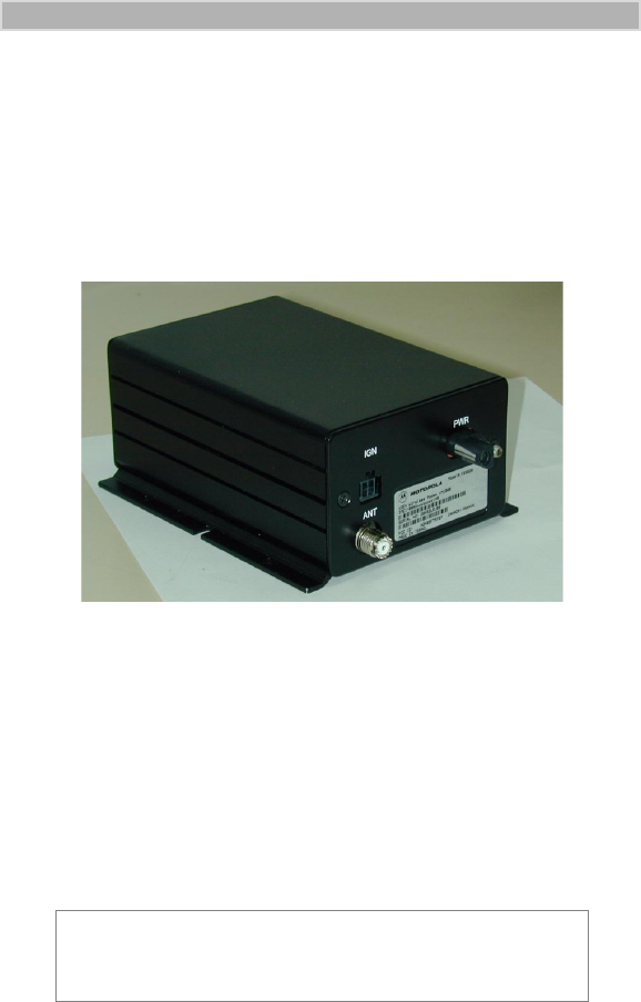
Figure 1. iM1000 Data Modem
C
iModem/user Page 1 Thursday, October 7, 1999 7:46 PM
2
iM1000 -Data Modem
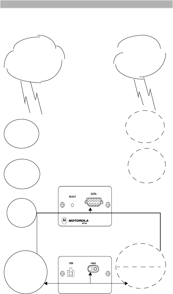
Overview
Packet Data
Internet
E-Mail
Circuit Data
Faxes
4.
Connect
to the
Internet
2.
Install the
Packet Data
Software
Connect
the Data Cable
and insert
pwr on plug
A.
Connect
the Data Cable
and insert the
pwr on plug
B.
Define the
Data Modem
C.
Start the
Communication
Software
1.
3.
Configure
the
modem
the
Front Panel
Back Panel
iModem/user Page 2 Thursday, October 7, 1999 7:46 PM

3
IM1000 - DATA MODEM
The iM1000 enables packet and circuit-data connections.
•
Packet data:
A wireless modem connection
for accessing the Internet,
sending and receiving e-mail, and transferring small files over the packet
data network using standard IP protocols.
Data is sent in bursts. Packet data transmits packets (blocks) of data at
high speed. After the data is transmitted, you can remain connected
indefinitely without being charged for the idle time
•
Circuit data:
A wireless modem connection for sending and receiving
faxes over the circuit-switched cellular channel.
Data is sent as a continuous stream through the network to another
modem.
To prepare your computer and iM1000 data modem for wireless data use,
the following procedures are necessary.
•
Connect the cable.
Connect the modem to the computer via the data cable.
For more information see “INSTALLATION INSTRUCTIONS” on
page 16.
•
Turn on the Modem.
Turn on the modem before you proceed with the installation and
configuration.
•
Set up Windows Components.
Use these instructions to verify that Dial-Up Networking and the TCP/IP
protocol are installed on your computer. If not, follow the procedure
provided to install them.
For more information, see “Verifying and Installing Dial-Up
Networking” on page 10 and “Verifying and Installing the TCP/IP
Protocol” on page 13.
•
Install the software.
Use the installation software to install the modem configuration data
software.
For more information, see “Installing the Software” on page 17.
•
Configure your iM1000 data modem.
Enter settings provided by your iDEN carrier.
For more information, see “CONFIGURING YOUR MODEM” on
page 31.
Connect to the Internet.
Start the Dial-Up Networking session. Be sure that the modem is
connected to the computer with the data cable. After successful
installation, you can surf the Internet, send and receive faxes and e-mail
messages, and transfer files.
NOTE
You may use the following information as a fast path to
installation.
iModem/user Page 3 Thursday, October 7, 1999 7:46 PM

4
iM1000 -Data Modem
The LED indicators located on the front panel of the iM1000 shows the
service state
Table 1: Status Light (LED) Indicator
Installation Requirements
To run the installation program, you need the following:
• An iM1000 unit
• A PC data cable for your data modem
• An IBM
®
-compatible PC with:
- An Intel
®
586 (or higher) processor
- Microsoft
®
Windows
®
95 installed, Windows
®
98 or Windows
®
NT
- Minimum 8 MB of addressable RAM
- CD-ROM drive
- 6 MB free hard-disk space
- Recommended: Mouse or compatible pointing device
• The installation software that came with your package
• Communication software
• An account with an iDEN carrier
LED Indicator Status of Your iM1000
Alternating Red
and Green
A fatal error has been detected
during power-up
Flashing Red Registering - your iM1000 is signing
on to your carrier’s network. Please
wait.
Solid Red No service -your iM1000 cannot
sign on. It will continue trying to
every two minutes as long as it is
turned on.
Flashing Green In service - your iM1000 has
successfully completed Packet Data
registration.
Solid Green In use - your iM1000 is currently
being used
iModem/user Page 4 Thursday, October 7, 1999 7:46 PM

5
HARDWARE INSTALLATION
HARDWARE INSTALLATION
Introduction
Hardware installation has to be carried out by experienced technicians
familiar with installing similar types of equipment.
Before You Start Installing
Ignition Sense Cable
Installation Planning
Planning is the key to fast, easy iM1000 installation. Before a hole is drilled
or a wire is run, inspect the vehicle and determine how and where you
intend to mount the antenna, iM1000, and accessories. Plan wire and cable
runs to provide maximum protection from pinching, crushing, and
overheating.
Recommended Tools For Installation
The following tools, screws, and washers are recommended for proper
installation of your iM1000.
• Portable Drill
• Hammer
• Center Punch
• Four screws M4
• Four self drilling screws M4
• Four flat washers M4
• Four spring washers M4
• Phillips #2 Screwdriver
NOTE
The iM1000 will not operate without the Ignition
Accessories Cable installed or a power on plug connected.
iModem/user Page 5 Thursday, October 7, 1999 7:46 PM

6
iM1000 -Data Modem
iM1000 Mounting
The standard mounting of the iM1000 can be mounted on different types of
mounting surfaces. Be sure the mounting surface is able to adequately
support the weight of the iM1000. Allow sufficient space around the
iM1000 for free air flow for cooling. Be sure the unit is close enough to the
vehicle operator to permit easy access to operating indicators. Although the
iM1000 can be mounted to a plastic dashboard, it is recommended that the
mounting screws be located so they penetrate the supporting metal frame of
the dashboard.
Antenna Mounting
The best mounting location for the antenna is in the center of a large, flat
conductive surface. In almost all vehicles, these requirements are best
satisfied by mounting the antenna at the center of the roof. Some vehicles
have a large trunk lid that provides a good antenna location. If the trunk lid
is used, connect grounding straps between the trunk lid and vehicle chassis
to ensure the trunk lid is at chassis ground.
Three types of antennas can be used:
1. RAFU136A - Magnetic Antenna
2. FAD5524A - Mobile Window Antenna
3. HAF9067A - Mobile Roof Mount Antenna
Make sure that you refer to the antenna installation instructions according to
the kit number.
DC Power Cable Installation
The iM1000 must be operated only in negative ground electrical systems.
Reverse polarity does not damage the iM1000; however, iM1000 protection
circuits cause the cable fuse to blow. Check the ground polarity before you
begin installation.
The DC power cable (FKN4448A) is long enough for installation in most
vehicles. Begin the power cable installation in the following manner.
1. Determine a routing plan for the power cable with reference to where
the iM1000 is to be mounted.
2. Locate the nearest available chassis ground mounting point and shorten
the black lead to remove excess cable length.
3. Locate the fuse holder as close to the battery as possible and away from
any hot component. Mount the fuse holder using the provided mounting
hole and dress wires as necessary. Connect the fuse holder red adapter
lead plus to the mating receptacle on the red lead of the power cable.
See Figure 3..
4. Connect the power cable black lead directly to the chassis ground.
5. Connect the power cable red lead from the fuse holder to the positive (+)
battery terminal. Make sure the adapter cable is connected to the main
power cable red lead.
6. Plug fuse into in-line fuse holder as shown in Figure 3..
iModem/user Page 6 Thursday, October 7, 1999 7:46 PM

7
HARDWARE INSTALLATION
Figure 2. - Power Cable Routing into the Engine Compartment
Figure 3. - Power Cable Assembly
Mounting iM1000 - Vehicle Installation
1. Select the location to mount your iM1000 - either on the transmission
hump or under the dashboard. When mounting the iM1000 on the
transmission hump, ensure that the transmission housing is not
affected.
2. Use the iM1000 mounting bracket as a template, mark the positions
of the holes on the mounting surface.
3. Secure the iM1000 mounting flinges to the surface with the four
(M4) screws provided.
4. Mount the antenna using the instructions provided with the antenna
kit. Run the coaxial cable to the iM1000 mounting location.
Black Lead
Red Lead
Firewall
Grommet
Engine Compartment
To Radio
FKN4448A
Fuse
Cover
Red Lead
Red Lead
Mounting
Hole
Molded In-Line
Fuse Holder
To Vehicle
Chassis Ground
Engine
Compartment To Battery (+)
Adapter
Firewall
Red Lead
Black Lead Ring
Lugs
iModem/user Page 7 Thursday, October 7, 1999 7:46 PM
8
iM1000 -Data Modem
If necessary, cut off the access cable and install the cable connector.
5. To assure compliance with United States FCC regulations on RF
exposure, position the antenna in such a way to maintain a
separation distance of at least 8 inches (20 cms) between the
antenna and the body of any user and nearby person. Connect the
antenna cable connector to the radio antenna connector on the rear
of the iM1000. See Figure 4.
6. Plug the power cable into the iM1000 power connector.
Figure 4. - Connections to iM1000 Rear Panel
Power Configuration
To turn ON the iM1000 modem, an ignition signal is required at the ignition
connector. It can be supplied in two ways.
Switched Power Connection
When installed in a vehicle, the modem receives the ignition signal from the
vehicle’s ignition switch.
NOTE
The modem operates only when the car switch is turned
ON.
iModem/user Page 8 Thursday, October 7, 1999 7:46 PM

9
HARDWARE INSTALLATION
Figure 5. Switched Power Connection
Perform the following steps to install the iM1000 modem in a vehicle:
1. Prepare a routing plan for the ignition cable after determining where
the iM1000 is to be mounted.
2. Connect the free end of the ignition cable to the vehicle ignition
switch, and the other end (with the plug) to the iM1000 ignition
connector.
Continuous Power Connection
A power on plug is permanently plugged into the ignition connector. When
the power is supplied to the iM1000 DC Power Connector, the modem turns
ON.
Figure 6. Continuous Power Connection
Data Cable Installation
Connect one side of the 9-pin cable (FKN4369A) to the iM1000
communication connector and the other side to the DTE. Since the iM1000
is a modem, it can be connected only to DTE equipment, using a 9-pin to
9-pin cable.
IGN Ignition Cable
PWR
Car
Switch
Vehicle
Battery
iM1000
Antenna
Pwr Cable FKN4448A
FKN4868A
Antenna
iM1000
Power Source
Power On Plug
IGN
PWR
FLN9400A
FKN4448A
iModem/user Page 9 Thursday, October 7, 1999 7:46 PM

10
iM1000 -Data Modem
SETTING UP WINDOWS COMPONENTS
The Installation software automatically installs the packet data application
on your IBM PC-compatible computer with Windows installed.
Windows must have Dial-Up Networking Version 1.3 or later and the TCP/
IP protocol installed.
• If Dial-Up Networking and the TCP/IP protocol are installed, skip this
section and go to “INSTALLATION INSTRUCTIONS” on page 16.
• If you are not sure if they are installed, or if they are not installed,
proceed with the rest of these instructions.
Verifying and Installing Dial-Up Networking
This section provides the procedure for setting up Dial-Up Networking on
your Windows computer.
Make sure that your Windows installation media (CD) is available. You may
be asked to insert it later in the installation procedure.
1. From your Windows desktop, double-click “My Computer”.
2. Double-click “Control Panel”.
3. Double-click “Add/Remove Programs”. The Add/Remove Programs
Properties window opens.
4. Click the Windows Setup tab.
NOTE
If your version of Dial-up Networking is earlier than
Version 1.3, you can go to the Microsoft™ web site,
www.microsoft.com, to get the upgrade.
IMPORTANT
If your computer has a network card or a security program
that prevents IP address changes, see your system
administrator before attempting to install this program.
If your computer is connected to a network, be sure not to
remove the existing network protocols during Packet Data
installation.
iModem/user Page 10 Thursday, October 7, 1999 7:46 PM
11
SETTING UP WINDOWS COMPONENTS
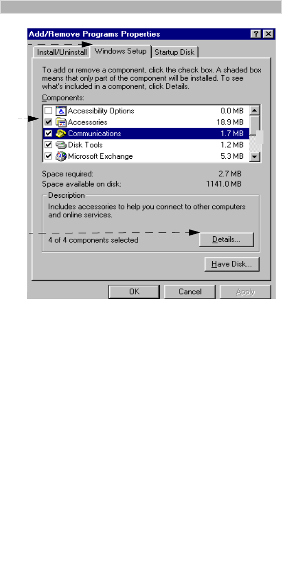
Figure 7. Add/Remove Programs - Windows Setup Window
5. Highlight “Communications” in the Components box.
6. Click “Details”. The Communications window opens.
4.
5.
6.
iModem/user Page 11 Thursday, October 7, 1999 7:46 PM
12
iM1000 -Data Modem
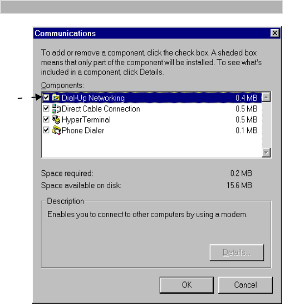
Figure 8. Communications Window
7. In the Communications window, perform the steps given in item (a.)
or (b.) below:
a. If the selection box to the left of “Dial Up Networking” has a
check mark in it, click “Cancel” to close the window. Click
“Cancel” again to close the Add/Remove Programs Properties
window.
b. If the selection box to the left of “Dial Up Networking” does not
have a check mark in it, click the selection box to place a check
mark in it. Click “OK” to close the window and then click “OK”
again to close the Add/Remove Programs Properties window.
Restart your computer.
8. Continue with “Verifying and Installing the TCP/IP Protocol” on
page 13.
7.
iModem/user Page 12 Thursday, October 7, 1999 7:46 PM
13
SETTING UP WINDOWS COMPONENTS
Verifying and Installing the TCP/IP Protocol
Use this procedure to ensure that your computer has the TCP/IP protocol
installed.
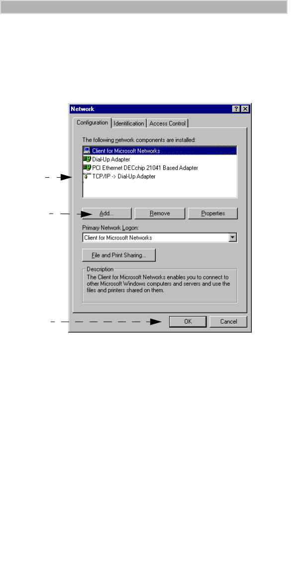
1. From the Control Panel on your desktop, double-click “Network”.
The Network window opens.
Your screen might not look exactly like
the one illustrated
.
Figure 9. Network Window
2. Scroll down the list to find “TCP/IP Dial-Up Adapter”.
3. Do one of the following:
a. If you see “TCP/IP -> Dial-Up Adapter” in the list, click “OK”.
Skip this section and go to “INSTALLATION INSTRUCTIONS”
on page 16.
b. If you do not see “TCP/IP -> Dial-Up Adapter” in the list, click
“Add”. The Select Network Component Type window opens.
2.
3b.
3a.
iModem/user Page 13 Thursday, October 7, 1999 7:46 PM
14
iM1000 -Data Modem
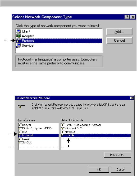
Figure 10. Select Network Component Type Window
4. Highlight “Protocol” then click “Add”. The Select Network Protocol
window opens.
Figure 11. Select Network Protocol Window
5. Under Manufacturer, select “Microsoft”.
6. Under Network Protocol, select “TCP/IP”, then click “OK”. The
TCP/IP Dial-Up Adapter appears in the list.
If the Dial-Up Adapter does not appear in the list, you do not have a
Dial-Up Adapter installed. You can install one. Use the procedure for
“Installing the Dial-Up Adapter” on page 15.
7. To close, click “OK”.
8. If the Dial-Up Networking adapter is installed, continue with
“INSTALLATION INSTRUCTIONS” on page 16.
4.
6.
5.
iModem/user Page 14 Thursday, October 7, 1999 7:46 PM
15
SETTING UP WINDOWS COMPONENTS
Installing the Dial-Up Adapter
When you select “TCP/IP Protocol”, you are asked to select a network
adapter. If you receive a message that you do not have one installed, use the
following procedure to install one. If you have a Dial-Up Adapter installed,
skip this section and go to “INSTALLATION INSTRUCTIONS” on page 16.
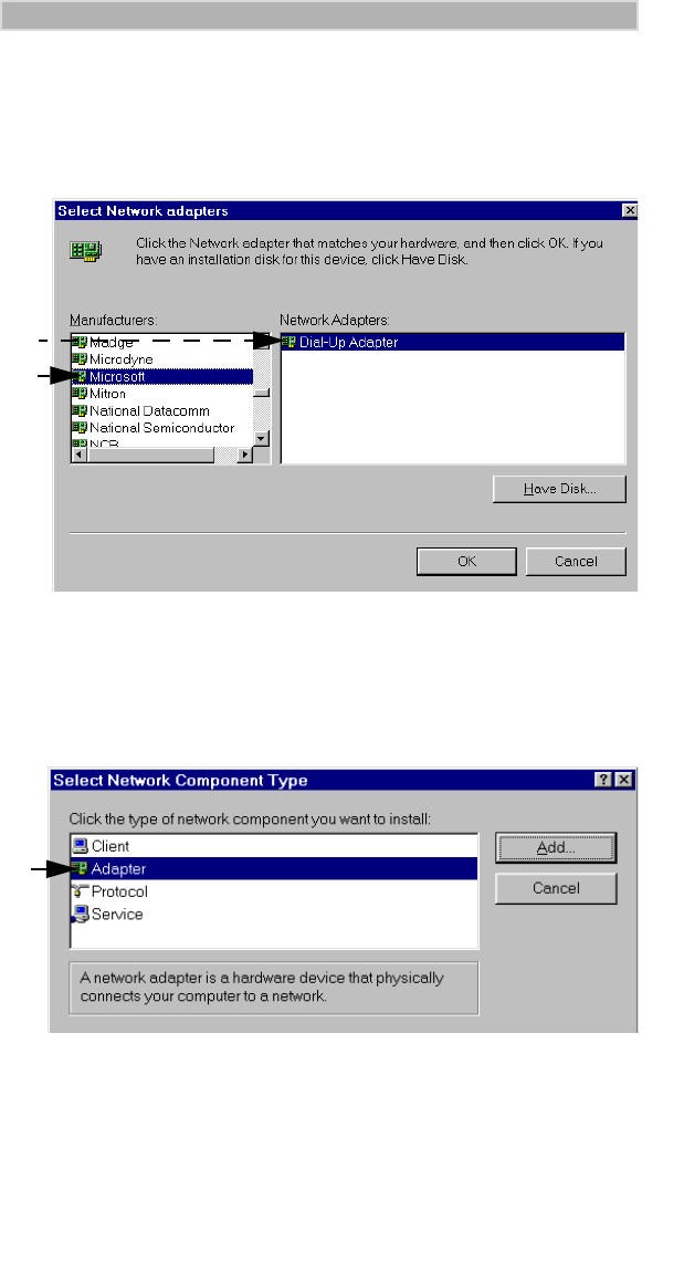
Figure 12. Select Network Adapter Window
1. At the Select Network Adapter window, under Network Adapters,
highlight “Dial-Up Adapter”.
2. Under Manufacturers, highlight “Microsoft”.
3. Click “OK”. The Select Network Component Type window opens.
Figure 13. Select Network Component Type Window
4. Highlight “Adapter” then click “Add”. The Select Network Adapters
window opens.
5. To verify that the adapter was added, from the Control Panel, click
Network. Look for “Dial-Up Adapter” on the Network Configuration
screen.
1.
2.
4.
iModem/user Page 15 Thursday, October 7, 1999 7:46 PM

16
iM1000 -Data Modem
INSTALLATION INSTRUCTIONS
This section provides information for connecting the data cable and
installing the software.
Connecting the Cable
Your computer and your modem can be turned on or turned off when you
connect the cable.
To connect the data cable:
1. Connect the data cable to the accessory connector on your modem.
2. Attach the other end of the cable to a serial communication (COM)
port on your computer or hand-held computing device.
3. Position the antenna of the radio product at least 8 inches (20cms)
away from the body of any person when transmitting.
To remove the cable:
1. Disconnect the data cable from your modem.
2. Disconnect the data cable from your computer.
NOTE
To instal the Wireless Data Services software on a computer
or hand-held device that does not have Windows installed,
or if you do not have the installation disks, proceed to
“Configuring the Modem for Packet Data— without the
Disk” on page 60.
iModem/user Page 16 Thursday, October 7, 1999 7:46 PM
17
INSTALLATION INSTRUCTIONS
Installing the Software
The Installation software enables packet data service.
To install the modem wireless data services software:
1. Turn on the power to your modem.
2. Turn on your computer and start Windows 95, Windows 98 or
Windows NT.
3. Insert the Installation CD-ROM in your CD-ROM drive.
4. Select “Start”, then select “Run”.
5. Type d:\setup (or substitute the correct drive letter).
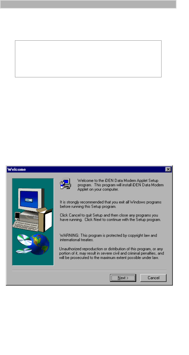
6. Click “OK”. The Setup progress window opens. After it closes, the
Welcome window opens.
Figure 14. Installation Welcome Window
7. Click “Next”. The User Information window opens.
IMPORTANT
During installation, if you receive a message that you do not
have one or more of the required Windows components
installed, see “SETTING UP WINDOWS
COMPONENTS” on page 10.
iModem/user Page 17 Thursday, October 7, 1999 7:46 PM
18
iM1000 -Data Modem
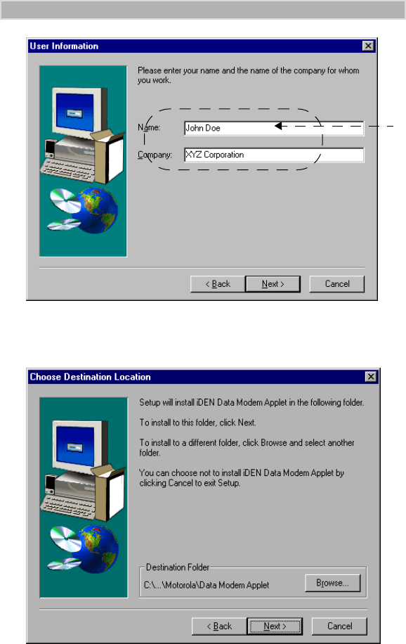
Figure 15. User Information Window
8. Enter your name and company, if it is not displayed.
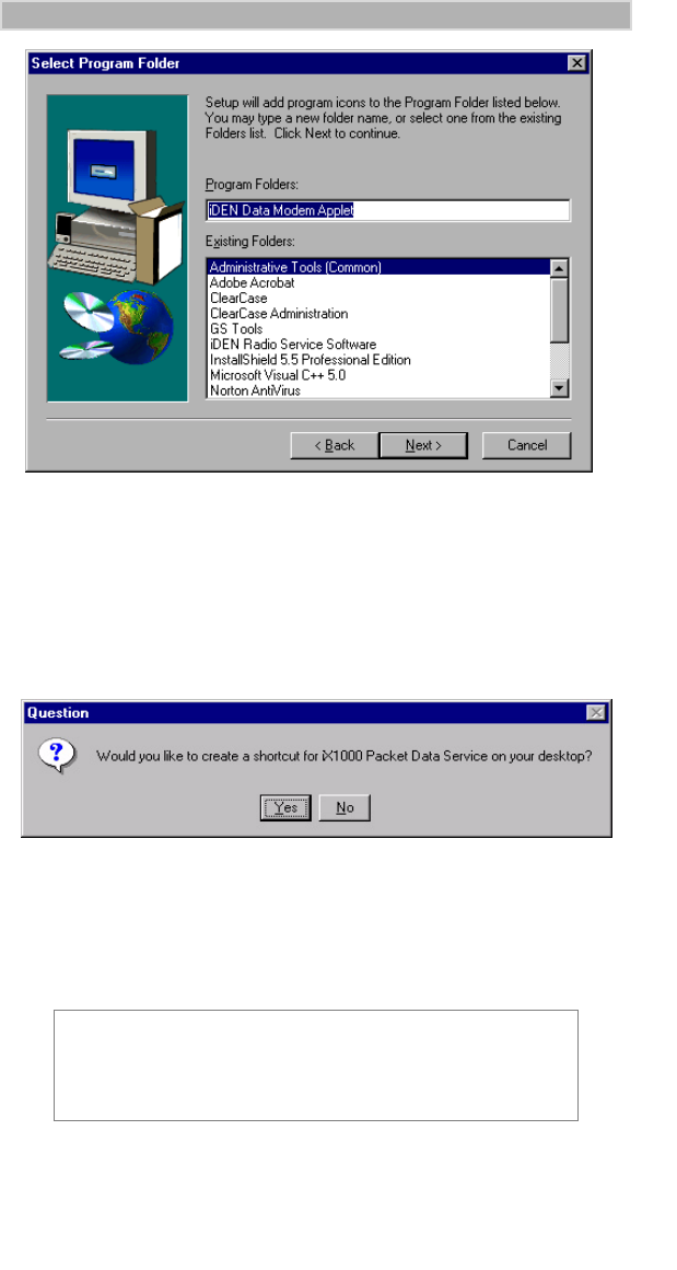
9. Click “Next”. The Choose Destination Location window opens.
Figure 16. Choose Destination Location Window
10. Click “Next” to accept the default Destination Folder. The Select
Program Folder window opens. “iDEN Data Modem Applet” is
highlighted.
8.
iModem/user Page 18 Thursday, October 7, 1999 7:46 PM
19
INSTALLATION INSTRUCTIONS
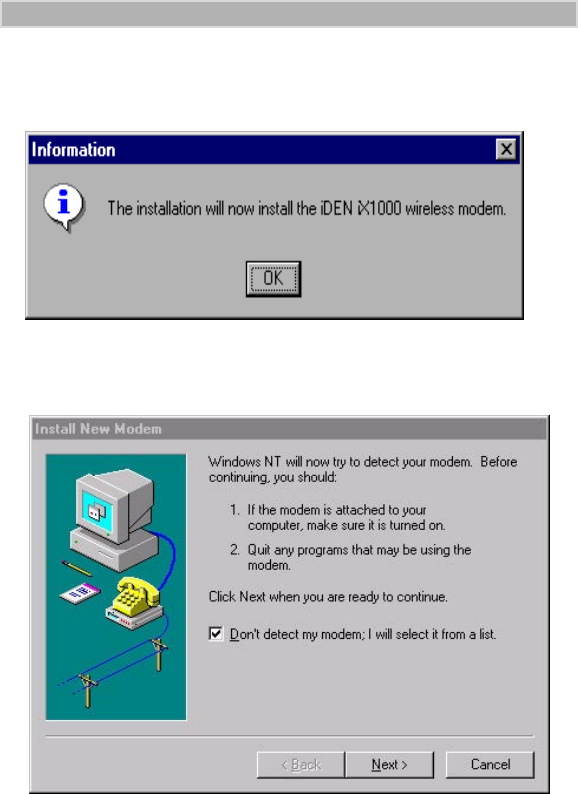
Figure 17. Select Program Folder Window
11. Click “Next” to accept the default Program Folder, iDEN Data Modem
Applet.
The installation program starts. A status window opens while the files
are copying.
After the files are copied, you can add a shortcut to your Windows
desktop.
Figure 18. Add a Shortcut
12. Select “Yes” to add a shortcut.
13. Make sure your modem is connected and turned on before you continue
the installation.
NOTE
To configure your system for Windows NT, proceed with
Steps 14 through 38. For Windows 95 and Windows 98, skip
to Step 39.
iModem/user Page 19 Thursday, October 7, 1999 7:46 PM
20
iM1000 -Data Modem
Windows NT Installation Only (Steps 14 - 38)
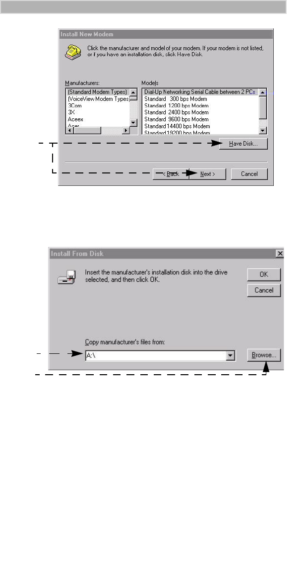
14. For Windows NT, an information window opens with a message that
wireless modem will be installed.
Figure 19. Begin Modem Installation
15. Click “OK”. The Installing New Modem window opens.
Figure 20. Modem Detect Window
16. If you do not want the system to take the time to search for a modem,
click “Don’t detect my modem. I will select it from a list”.
17. Click “Next” to continue. The Modem Selection Window opens.
iModem/user Page 20 Thursday, October 7, 1999 7:46 PM
21
INSTALLATION INSTRUCTIONS
Figure 21. Modem Selection Window
18. Click “Have Disk”, then click “Next”. The Install From Disk window
opens.
Figure 22. Install From Disk Window
19. Type the name of the drive that contains the CD.
20. Click Browse. The Locate File Window opens.
18.
19.
20.
iModem/user Page 21 Thursday, October 7, 1999 7:46 PM
22
iM1000 -Data Modem
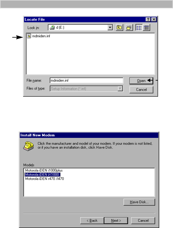
Figure 23. Locate File Window
21. Highlight the “mdmiden” file.
22. Click “Open”. The Locate File window opens again.
23. Click “OK”. The Install New Modem window opens.
Figure 24. Install New Modem Window
24. Make sure that “Motorola iDEN iX1000” is highlighted.
25. Click “Next”. The Port Selection Window opens.
21.
22.
iModem/user Page 22 Thursday, October 7, 1999 7:46 PM
23
INSTALLATION INSTRUCTIONS
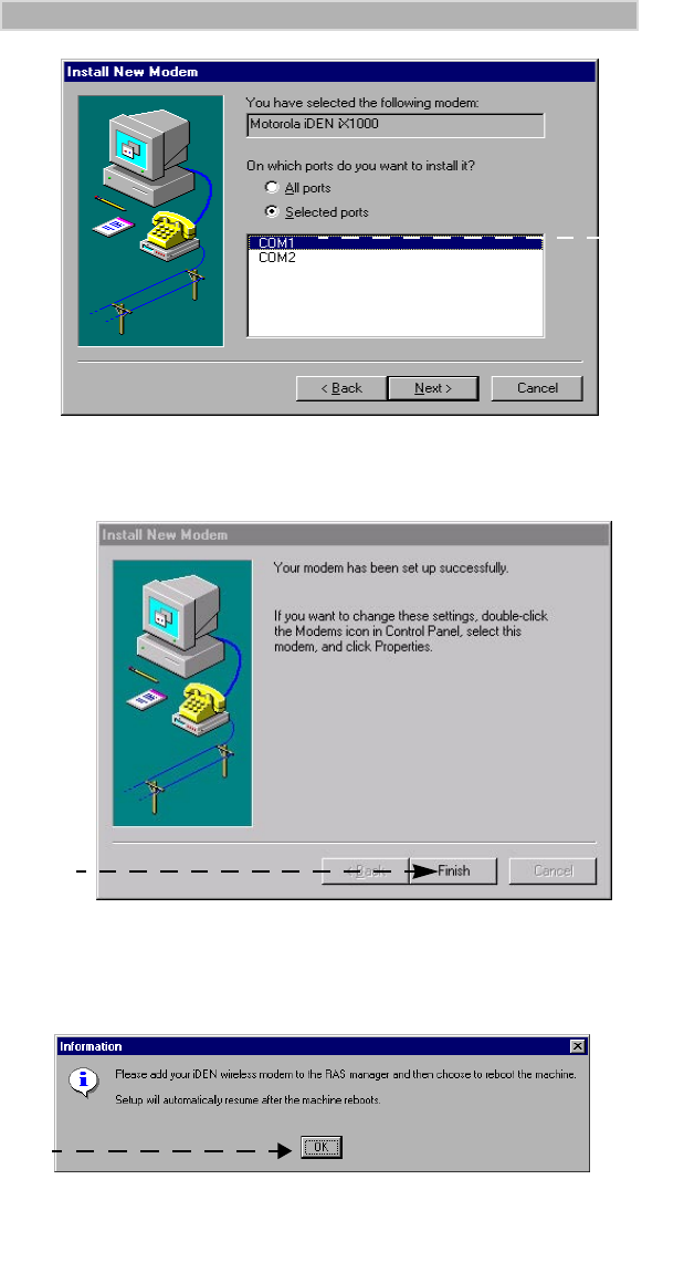
Figure 25. Port Selection Window
26. Highlight the COM port to which your modem is to be connected and
click “Next”. The Modem Installation Finish window opens.
Figure 26. Modem Installation Finish Window
27. Click “Finish”.
28. “Configure the Data Modem in RAS Manager Window” opens
Figure 27. Configure the Data Modem in
RAS Manager Window
27.
.
29.
26
iModem/user Page 23 Thursday, October 7, 1999 7:46 PM
24
iM1000 -Data Modem
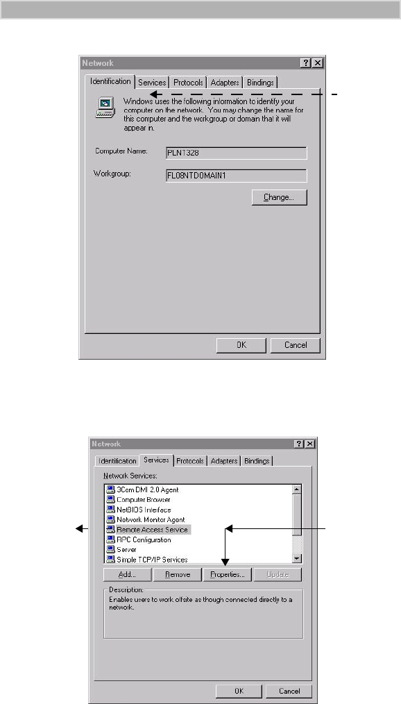
29. Click “OK”. The Network Configuration window opens.
Figure 28. Network Configuration Window
30. Click “Services”. The Network Services Selection window opens.
Figure 29. Network Services Selection Window
31. Highlight “Remote Access Service” and click “Properties”.
The Remote Access Setup window opens.
30.
31. 31.
iModem/user Page 24 Thursday, October 7, 1999 7:46 PM
25
INSTALLATION INSTRUCTIONS
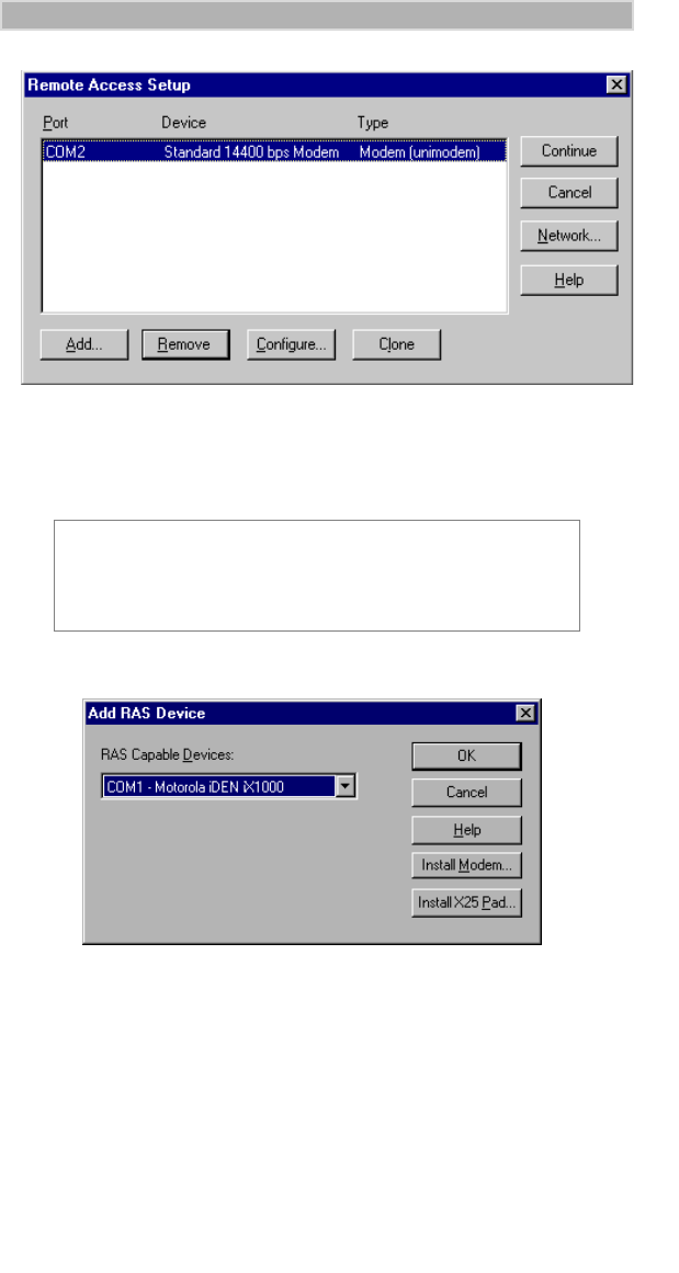
Figure 30. RAS Access Setup Window
.
32. Click “Add”. The Add RAS Device window opens.
Figure 31. Add RAS Devices Window
33. Make sure that the COM port of your iX1000 modem is selected
(COM1 in this example).
34. Click “OK”. The Remote Access Setup window now shows the added
COM port. Click “Continue”.
35. Click “Close” on the Network Services Selection window.
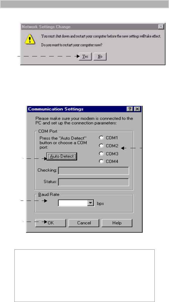
36. The Computer Restart window opens. Click “Yes”
NOTE
If a modem is already inserted in the same COM port as the
data-capable modem, click “Remove” to remove it and then
click “Add”.
iModem/user Page 25 Thursday, October 7, 1999 7:46 PM
26
iM1000 -Data Modem
.
Figure 32. Computer Restart Window
37. When the Windows banner appears during the computer restart, “log
on”.
38. The installation will automatically resume.
Figure 33. Communication Settings Window.
39. At the Communications Settings window, do one of the following:
• Click “Auto Detect” to have the program automatically detect the
IMPORTANT
There is a baud rate setting for your computer and a baud
rate setting for your modem. If you do not choose
AutoDetect and accept the default baud rate of 19200, be
sure the settings for the computer and the modem are the
same. If they are not, your computer might have a problem
connecting with the modem.
36.
39.
39.
40.
41.
iModem/user Page 26 Thursday, October 7, 1999 7:46 PM
27
INSTALLATION INSTRUCTIONS
communication port to which your modem is connected and set the
corresponding COM port button.
• Or, select a COM port by clicking its selection button
40. Optional: If you want to change the baud rate, click the down arrow to
make another selection.
Be sure that “Done” appears in the Status box before you continue
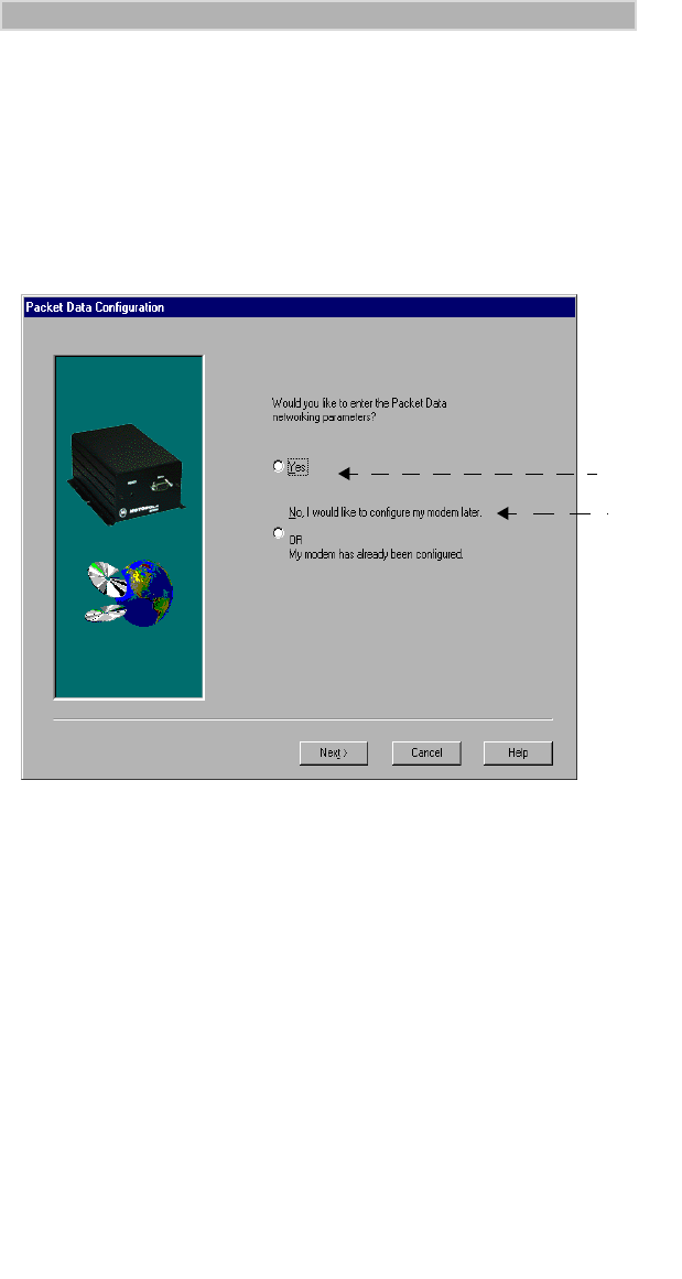
41. Click “OK”. The Packet Data Configuration window opens.
Figure 34. Packet Data Configuration Window
42. a. Click “Yes” to configure your modem now.
b. Click “No” to configure your modem later.
This would also be your choice if modem is already configured.
Setup is complete.
43. Click “Next”. If you have selected “Yes” previously, then the Packet
Data Configuration-2 window opens.
42 a
42 b
iModem/user Page 27 Thursday, October 7, 1999 7:46 PM
28
iM1000 -Data Modem
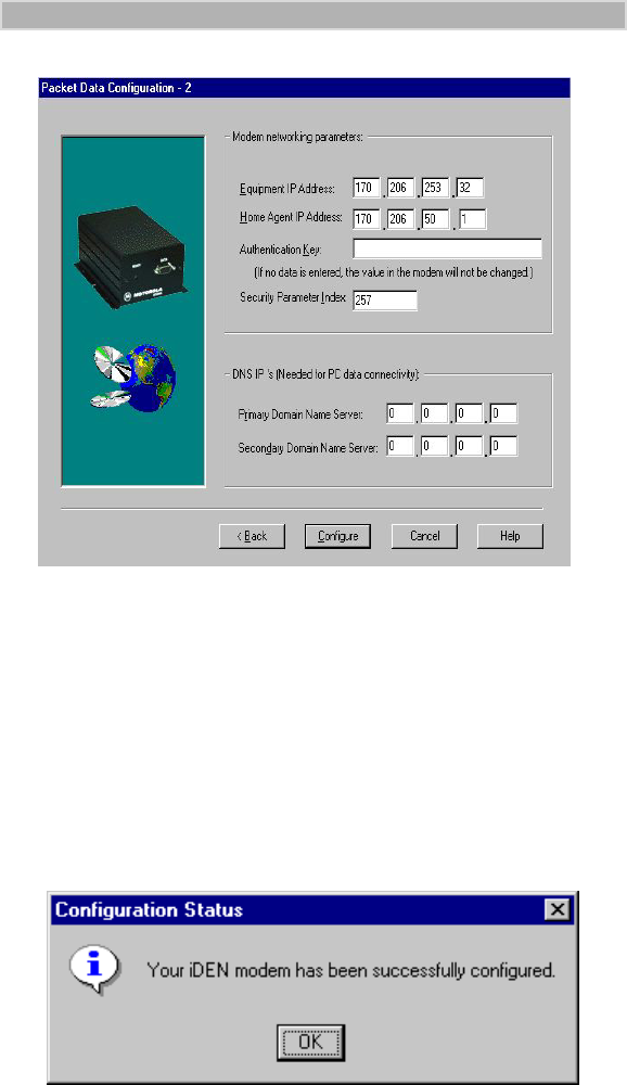
Figure 35. Packet Data Configuration-2 Window
44. Enter the following information: Some of this information may already
be entered for you.
• Equipment IP Address
• Home Agent IP Address
• Authentication Key
• Security Parameter Index
• Primary Domain Name Server
• Secondary Domain Name Server
45. Click “Configure”. The Configuration Status window opens with the
below message.
Figure 36. Configuration Status Window
46. Click “OK”. The “setup complete window” appears
iModem/user Page 28 Thursday, October 7, 1999 7:46 PM
29
INSTALLATION INSTRUCTIONS
For Windows NT
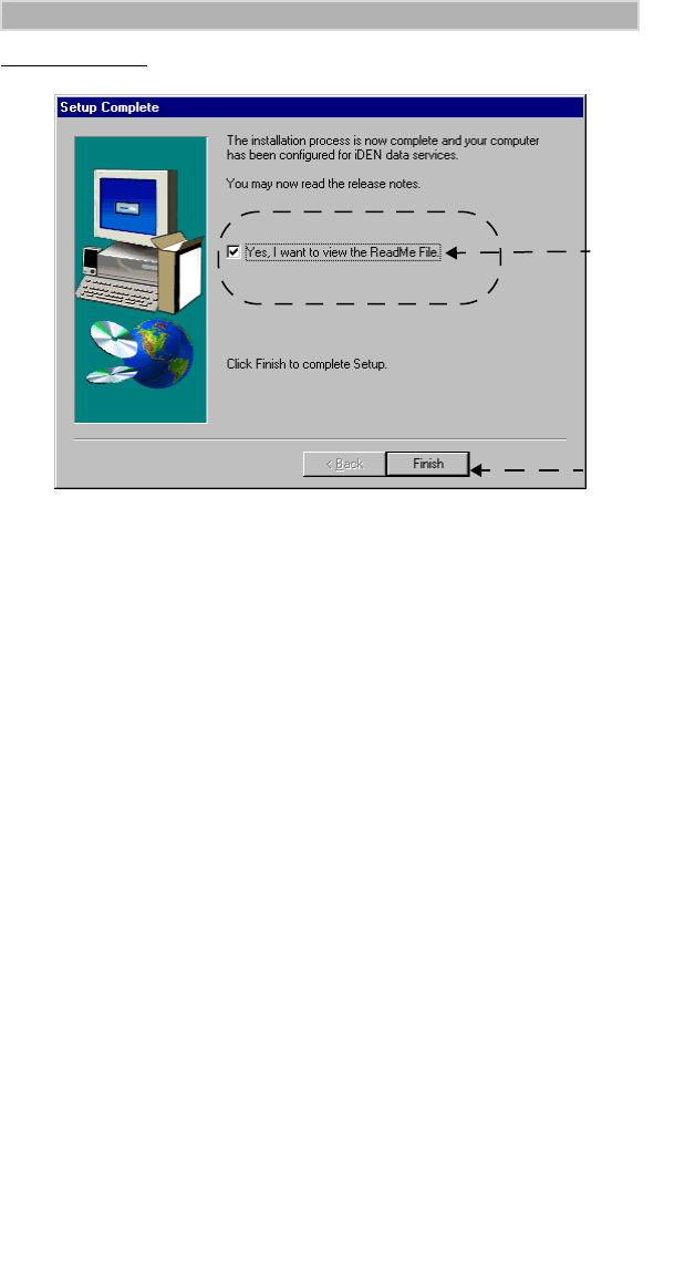
Figure 37. Windows NT, “Setup Complete” Window
47. At the Setup Complete window, to read the ReadMe file now, leave the
check mark. To read it later, remove the check mark.
48. Click “Finish”. The iDEN Data Modem Applet window appears on
your desktop.
48.
47
iModem/user Page 29 Thursday, October 7, 1999 7:46 PM
30
iM1000 -Data Modem
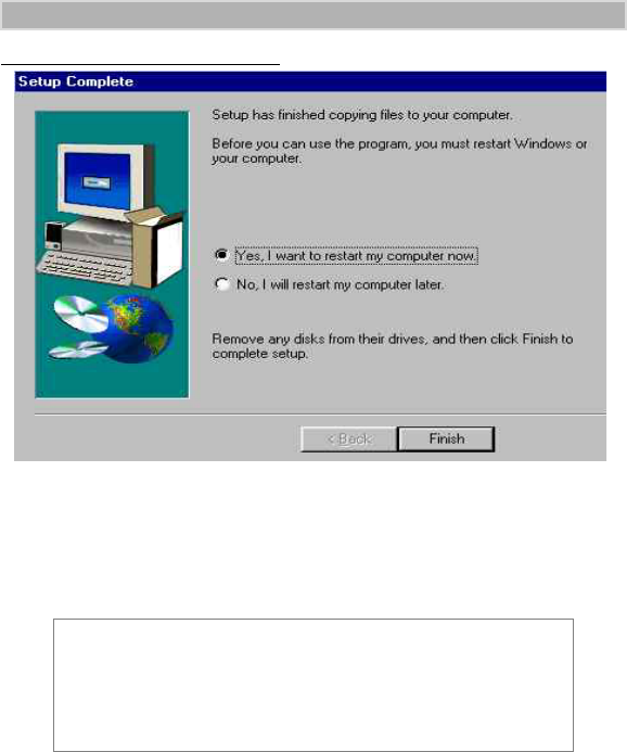
For Windows 95 and Windows 98
Figure 38. Windows, “Setup Complete” Window
49. At the setup complete window choose “Yes, I want to restart my
computer now” and click “Finish”
50. Continue with “CONFIGURING YOUR MODEM” on page 31.
NOTE
If you want to use the data cable and your computer to run
applications, continue with “CONFIGURING YOUR
MODEM” on page 31.
Otherwise, installation is complete.
iModem/user Page 30 Thursday, October 7, 1999 7:46 PM
31
CONFIGURING YOUR MODEM
CONFIGURING YOUR MODEM
The next step is to set up your computer and modem for packet data and
circuit-switched data services.
Setting Up Your Computer and Modem for
Packet Data Services
If you did not choose to configure your iDEN modem during software
installation, perform the following steps:
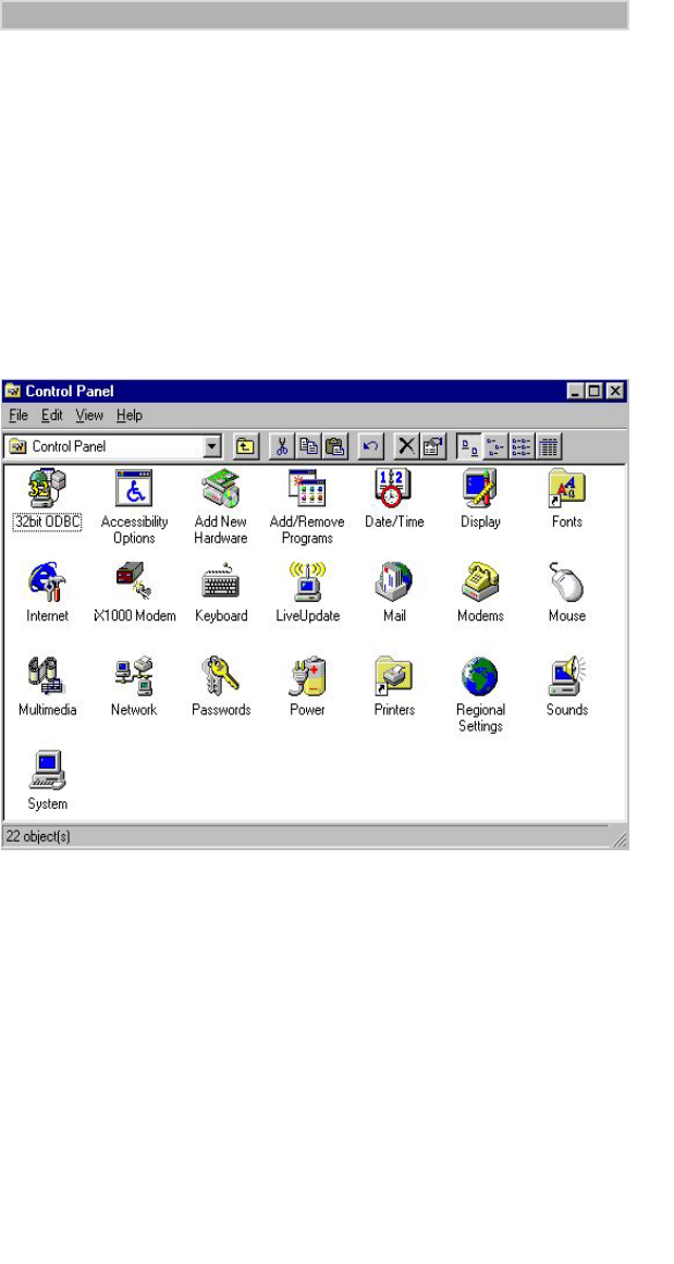
1. From your Windows desktop, double-click “My Computer”.
2. Double-click “Control Panel”. The Control Panel window opens.
Figure 39. Control Panel Window
3. Double-click “iX1000 Modem”. The Wireless Network Profile
Selection Window opens.
iModem/user Page 31 Thursday, October 7, 1999 7:46 PM
32
iM1000 -Data Modem
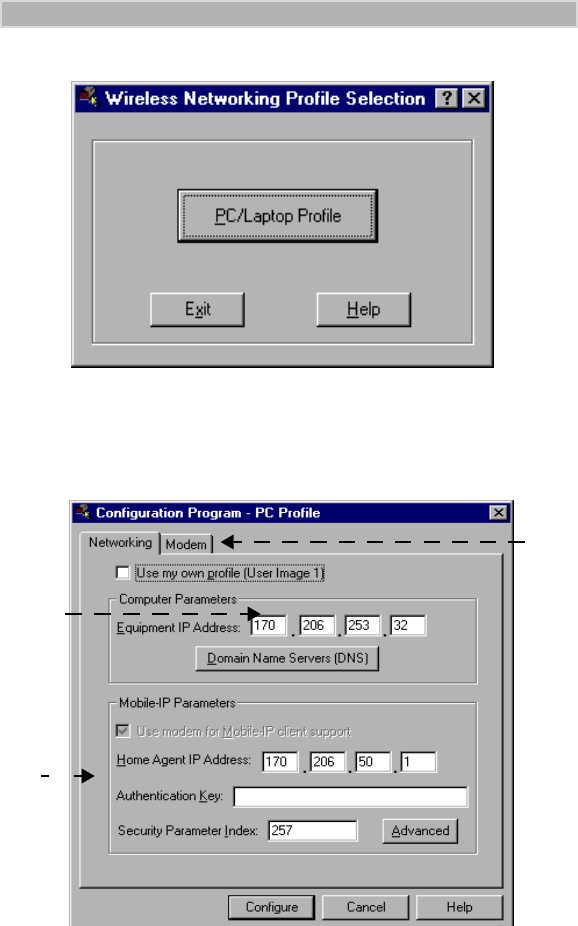
Figure 40. Wireless Networking Profile Selection Window
4. Click “PC/Laptop Profile”. The Configuration Program-PC Profile
window opens with the Networking tab active.
Figure 41. PC/Laptop Networking Window
5. Enter the modem’s IP address, as provided by your iDEN carrier, if it
is not already entered.
6. Enter information in the rest of the fields as provided by your iDEN
carrier. Some of this information may already be entered.
7. Click “modem”. The modem Settings window opens.
7.
5.
6.
iModem/user Page 32 Thursday, October 7, 1999 7:46 PM
33
CONFIGURING YOUR MODEM
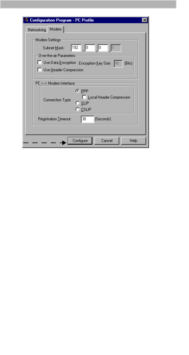
Figure 42. Modem Settings Window
8. Make sure the settings match those shown in Figure 42.
9. When you finish, click “Configure” to save your information. A
window opens to indicate that your modem is successfully configured.
10. Click “OK”. The Wireless Network Profile Selection window
reappears. Click “Exit”.
Verifying Modem Installation
To verify that your modem definition is installed:
1. From your Windows desktop, double-click “My Computer”.
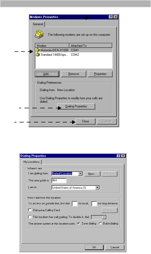
2. Double-click “Control Panel” and then double-click “Modems”. The
Modem Properties window opens.
3. Make sure the Motorola iDEN iX1000 modem is on the displayed list.
9
iModem/user Page 33 Thursday, October 7, 1999 7:46 PM
34
iM1000 -Data Modem
Figure 43. Modems Properties Window
4. If you have special dialing requirements, click “Dialing Properties”.
The Dialing Properties window opens. Enter the appropriate
information and click “OK”.
Figure 44. Dialing Properties Window
5. In the Modem Properties window, click “Close” again.
6. Close the Control Panel window.
3.
4
5.
iModem/user Page 34 Thursday, October 7, 1999 7:46 PM
35
CONFIGURING YOUR MODEM
Creating a Dial-Up Networking Connection in
Windows
The setup program attempts to create the dial-up networking connection
automatically. However, some versions of Windows 95 require that you
create it manually. If you get such a message, use the following procedure.
If you do not have to create a dial-up networking connection, proceed to
“STARTING THE INTERNET CONNECTION” on page 40.
To create a packet data connection:
1. Be sure that your computer has Dial-Up Networking and TCP/IP
installed. (For more information, see “Verifying and Installing Dial-
Up Networking” on page 10 and “Verifying and Installing the TCP/IP
Protocol” on page 13.)
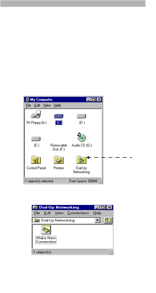
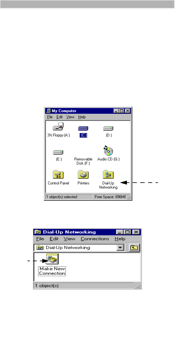
2. From your Windows desktop, double-click “My Computer”.
Figure 45. My Computer
3. Double-click “Dial-Up Networking”. The Dial-Up Networking
window opens.
Figure 46. Dial-Up Networking Window
4. Double-click “Make New Connection”. The Make New Connection
window opens.
3.
iModem/user Page 35 Thursday, October 7, 1999 7:46 PM
36
iM1000 -Data Modem
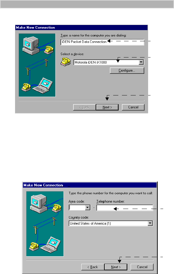
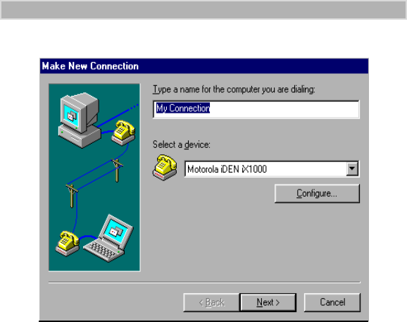
Figure 47. Make New Connection Window
5. At “Type a name for the computer you are dialing”, type iDEN Packet
Data Connection.
6. At “Select a modem”, if the Motorola iDEN modem does not appear,
click the down arrow and select it.
7. Click “Next” to confirm this selection. The Make New Connection
window changes and now displays fields for entering the modem
number.
Figure 48. Entering a Phone Number
8. At “Telephone number”, enter S=2.
9. Click “Next” to confirm this selection.
The next screen informs you that you successfully created a new Dial-
Up Networking connection called “iDEN Packet Data Connection”,
the same name you previously entered.
3.3.3.5.
6.
7.
8.
S=2
9.
iModem/user Page 36 Thursday, October 7, 1999 7:46 PM
37
CONFIGURING YOUR MODEM
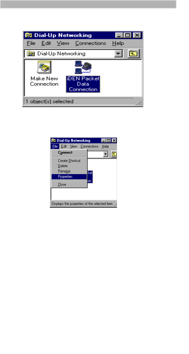
10. Click “Finish”. This procedure creates the iDEN Packet Data
Connection icon in the Dial-Up Networking window.
Figure 49. iDEN Packet Data Connection Icon
11. Click (do not double-click) “iDEN Packet Data Connection” to
highlight it. The Dial-Up Networking window opens.
Figure 50. Dial-Up Networking Window
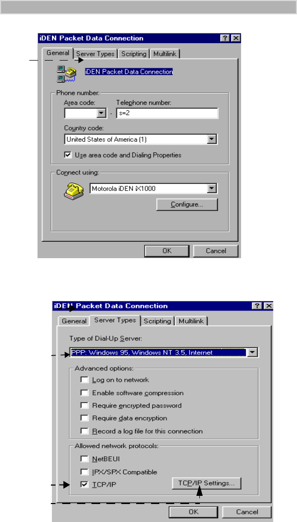
12. From the pull-down menu, click “File”, then click “Properties”. The
iDEN Packet Data Connection window opens.
iModem/user Page 37 Thursday, October 7, 1999 7:46 PM
38
iM1000 -Data Modem
Figure 51. iDEN Packet Data Connection Window
13. Click “Server Types”. The Server Types window opens.
Figure 52. Server Types Settings
14. Make sure the “Type of Dial-Up Server” is
PPP:Windows 95, Windows NT 3.5, Internet.
13.
15.
16.
14.
iModem/user Page 38 Thursday, October 7, 1999 7:46 PM
39
CONFIGURING YOUR MODEM
15. Make sure that the selection box next to “TCP/IP” is checked. Remove
the check marks from all other selection boxes.
To remove a check mark, click on it.
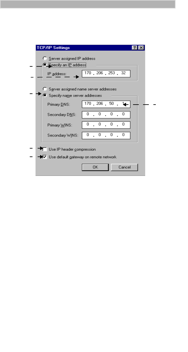
16. Click “TCP/IP Settings”. The TCP/IP Settings window opens.
Figure 53. TCP/IP Settings Window
Your iDEN carrier provides your Primary and Secondary DNS IP
addresses.
17. Make sure that the selection button next to “Specify an IP address” is
selected.
18. Enter the IP address for the modem.
19. Make sure that the selection button next to “Specify name server
addresses” is selected.
20. Enter the Primary DNS IP address provided by your iDEN carrier.
21. (Optional) Check the selection box next to “Use IP Header
Compression”.
22. Make sure that the selection box next to “Use default gateway on
remote network” is checked.
23. Continue clicking “OK” to return to the Dial-Up Networking window,
then close it.
22.
21.
18.
17.
19.
20
iModem/user Page 39 Thursday, October 7, 1999 7:46 PM
40
iM1000 -Data Modem
STARTING THE INTERNET
CONNECTION
There are two ways that you can connect to the Internet with an iDEN
modem: packet data and circuit-switched data.
• Packet Data—uses an IP address rather than a modem number.
• Circuit-Switched Data—uses a data modem number.
Connecting with Packet Data Services
When a packet-data connection is active, your Internet service provider is
your iDEN carrier.
If you have not connected the data cable to the computer and your modem,
do so now. If you need instructions, see “This section provides information
for connecting the data cable and installing the software.” on page 16.
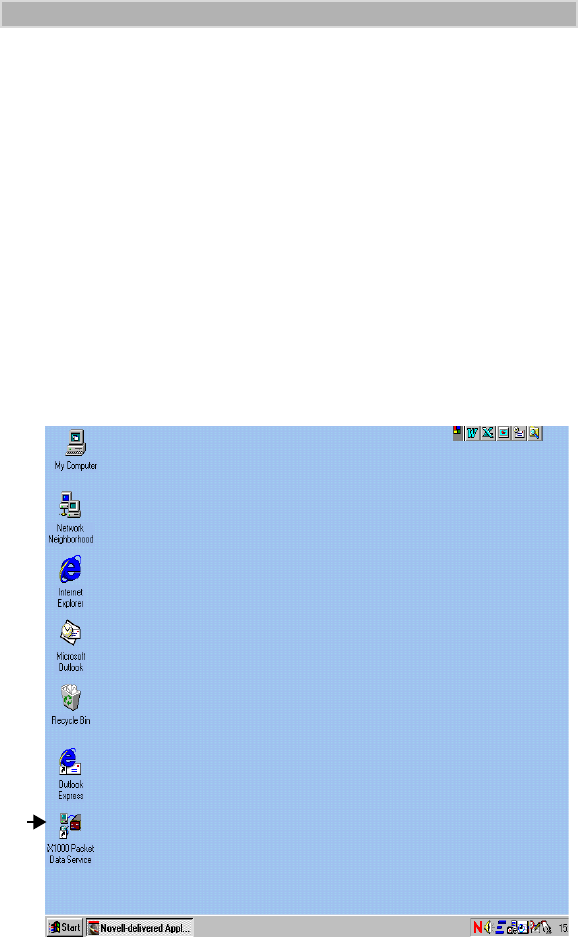
Figure 54. iX1000 Packet Data Service Icon
1. From your Windows desktop, double-click “iX1000 Packet Data
Service”. The Dialer window opens.
If you do not have this icon on your desktop, click Start, Programs,
iDEN Data Modem Applet, Status Program.
1.
iModem/user Page 40 Thursday, October 7, 1999 7:46 PM
41
STARTING THE INTERNET CONNECTION
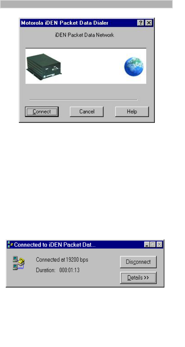
Figure 55. Dialer Window
2. Click “Connect”. As the connection starts, you’ll see the following
messages:
CONNECTING
CONNECTED SUCCESSFULLY
After You Are Connected to the Internet
The LED located on the front panel of the modem flashes green to indicate
that your modem is packet-data registered.
Your Computer
• Displays the “Connected to iDEN Packet Data” window. Simply glance
at your computer screen to get the current connection baud rate and
duration of the connection.
Figure 56. Packet Data Status Window
iModem/user Page 41 Thursday, October 7, 1999 7:46 PM
42
iM1000 -Data Modem
You can end your Packet Data connection by clicking “Disconnect”.
• Displays the “iDEN Packet Data Services” window, which provides a
convenient picture of your modem’s current signal strength.
Figure 57. iDEN Status Window
You can view the expanded status box by clicking “Mode” then “Advanced”.
For more information about the iDEN status window, see “Using the iDEN
Packet Data Service Window” on page 43.
• Displays a modem icon on the Taskbar. You can open the status box by
clicking on the modem icon.
Figure 58. Modem Status Icon on the Taskbar
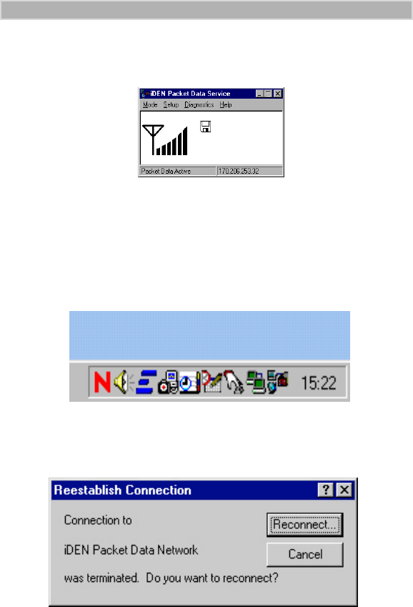
If You Lose Your Connection
If you lose your connection, you will see the following message:
Figure 59. Reestablish Connection
To re-establish your connection, click “Reconnect”.
iModem/user Page 42 Thursday, October 7, 1999 7:46 PM
43
STARTING THE INTERNET CONNECTION
When You Are Connected
After you send data, the packet data transfers take place during times when
the iDEN network is not busy. This operation is like sending a letter through
the post office. You do not have simultaneous contact with the addressee.
Using the iDEN Packet Data Service Window
The iDEN Packet Data Service window on
your computer screen informs you of the
current status of your modem during a
packet data connection.
You can turn this option on and off. It is not
required to use packet data services.
• Normal mode provides signal strength.
• Advanced mode displays technical information
about iDEN carrier and signal strength.
If the computer cannot connect with the modem, your computer will display
an error message
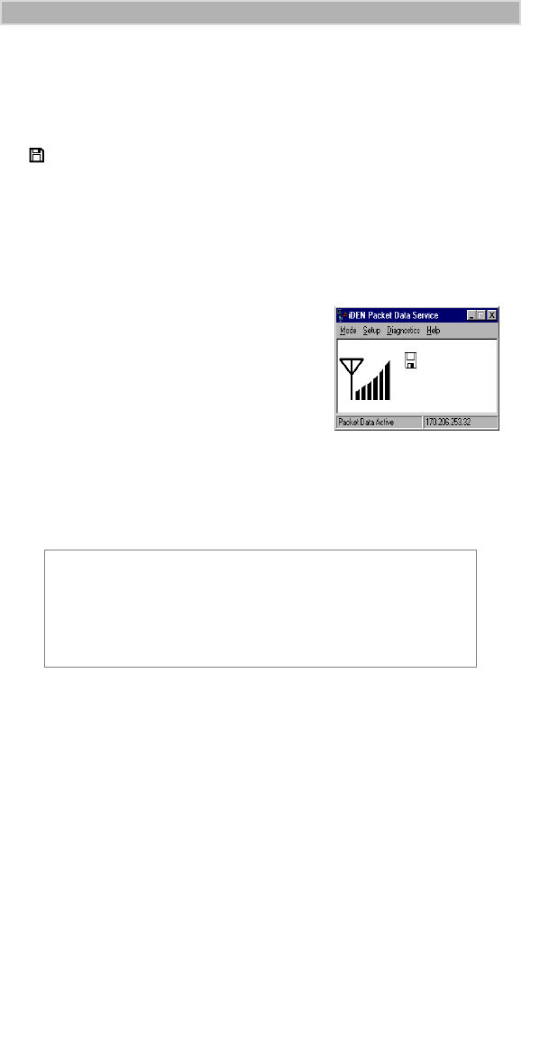
When your iDEN modem is connected to your computer with the data
cable, and your packet data modem is selected, you are Packet Data
Registered even if you are not actively transmitting data.
Your PC displays a floppy disk icon, indicating that your
modem is ready to make packet data calls.
NOTE
If the iDEN Packet Data Service window is not on your
computer screen, you can open it by double-clicking the
modem icon on the Windows 95, Windows 98, or Windows
NT Taskbar.
iModem/user Page 43 Thursday, October 7, 1999 7:46 PM
44
iM1000 -Data Modem
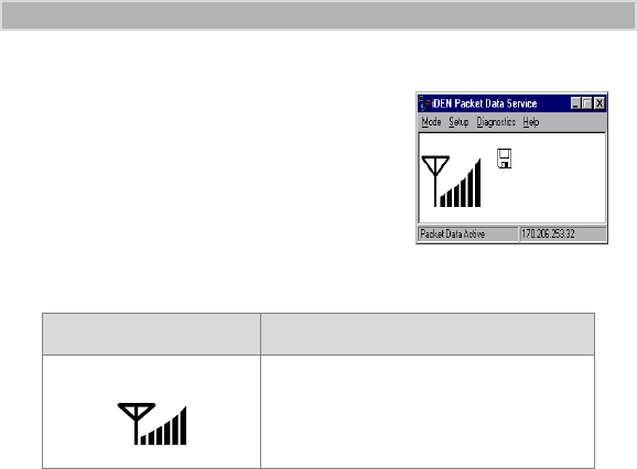
Normal Mode
Normal mode indicates that communication
with your iDEN modem has started. A status
message displays with the appropriate
indicators.
The following table describes the indicators
that appear in Normal mode.
For more information, click your right mouse button in the status window
where the indicators reside, and make a selection from the pop-up menu.
The menu choices are:
Table 2: iDEN Communication Indicators
Indicator Description
Signal Strength This indicator displays six bars
when the signal is strongest.
Advanced Provides technical information about your
carrier and signal strength. Normally, you
would not need to view this information.
Help Click to get help for iDEN Packet Data Service
window.
About Click to get product information, such as
manufacturer, software name and version,
copyright and licensing information.
Exit Click to close the pop-up menu.
iModem/user Page 44 Thursday, October 7, 1999 7:46 PM

45
STARTING THE INTERNET CONNECTION
Advanced Mode
To open the Advanced Mode window:
1. From the Normal mode window, click “Mode”.
2. Click “Advanced”. The Advanced Mode window opens.
Figure 60. iDEN iX1000 Status Window - Advanced
The following information is displayed:
Advanced mode also has a pop-up menu. To access the pop-up menu, click
your right mouse button in the status window.
The menu choices are:
If you see the following status message:
CANNOT COMMUNICATE WITH MODEM...
the computer does not recognize the IP address of the modem. If the IP
address conflicts with the one given to you by your iDEN carrier, run the
configuration program to synchronize the IP addresses. See
“CONFIGURING YOUR MODEM” on page 31.
Carrier
No. The hexadecimal equivalent for the carrier
number of a cell
Color
Code The hexadecimal value for the carrier color
code
SQE The decimal value for the Signal Quality
Estimate in decibels (dB)
RSSI The value that represents the signal strength
power received in dBm units.
Normal Click to view the basic information for your
modem.
Help Click to get help for the status window panel.
About Click to get product information, such as
manufacturer, software name and version,
copyright and licensing information.
Exit Click to close the program.
iModem/user Page 45 Thursday, October 7, 1999 7:46 PM
46
iM1000 -Data Modem
Running Applications over Packet Data
You can run any standard TCP/IP application during a packet data session.
To start a packet-data session, double-click the iX1000 Packet Data Services
icon.
This means that any software specifically configured for use with other
service providers might need to be reconfigured for use with your iDEN
carrier.
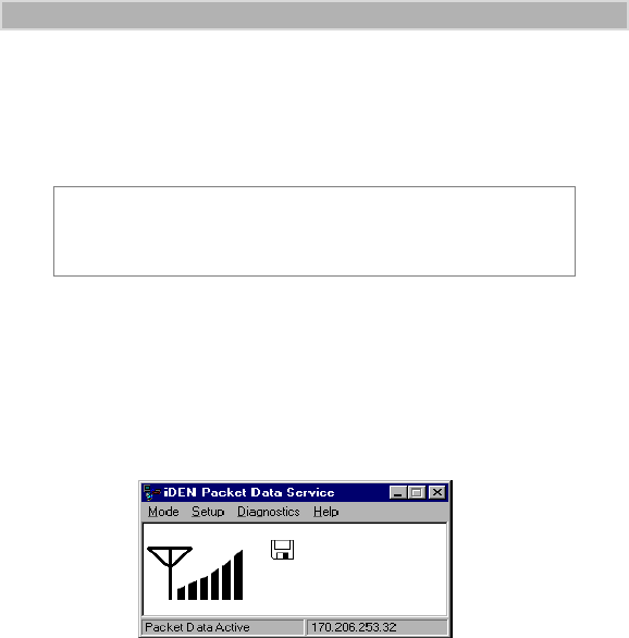
Ending a Packet Data Call
To end a packet data call:
Figure 61. iDEN Status Window
• If the status window is open, click the button marked X at the upper right
corner of the iDEN Status window. This disconnects your modem from
the network and closes the status window.
• If the status window is closed, click the modem icon on your desktop
taskbar to open the status window. Then click the X at the upper right
corner of the iDEN Status window.
NOTE
When a packet-data session is active, your service provider
is your iDEN carrier and not an Internet service provider.
iModem/user Page 46 Thursday, October 7, 1999 7:46 PM
47
STARTING THE INTERNET CONNECTION
Connecting to the Internet via Circuit-Switched
Data
Circuit-switched data communications use AT commands, which are issued
by your computer to your modem or, during fax transmissions, to the
modem at the other end of the connection.
AT commands refer to Hayes®-compatible modem commands.
Make sure you have a Motorola iDEN data-enabled modem definition
installed. For more information, see “CONFIGURING YOUR MODEM”
on page 31.
To make a circuit-switched data connection:
1. From your Windows 95, desktop, double-click “My Computer”.
Figure 62. My Computer Window
2. Double-click “Dial-Up Networking”. The Dial-Up Networking
window opens.
Figure 63. Dial-Up Networking Window
3. Double-click “Make New Connection”. The Make New Connection
window opens.
2.
3.
iModem/user Page 47 Thursday, October 7, 1999 7:46 PM
48
iM1000 -Data Modem
Figure 64. Make New Connection Window
4. At “Select a modem”, select the name of the Motorola iDEN modem.
5. Click “Next”. Follow the instructions for your Internet Service
Provider (ISP).
Your ISP is not your iDEN carrier.
6. Wait for the connection with your ISP to be established.
7. Start your application software (such as, Netscape® Navigator™ or
Microsoft™ Internet Explorer).
iModem/user Page 48 Thursday, October 7, 1999 7:46 PM

49
FAX SERVICES
FAX SERVICES
You can send and receive faxes using your existing Class 2-compatible
communications software.
You will not hear a dial tone during dialing operations.
Sending Faxes
To send a fax message:
1. Connect your modem to the computer and make sure that both are
turned on.
2. Start your fax communication software.
3. Dial the desired phone number.
Use the standard procedure for your communication software or
choose the number from a dialing directory.
4. After the connection is established, send the fax message. If you
desire to attach a cover sheet, follow the instructions that came with
your communication software.
Receiving Faxes
To receive a fax message:
1. Follow the instructions in steps 1 and 2 for sending faxes above.
2. Use the AT command to set your modem to “Auto Answer”.
3. While the entire fax message is transmitting, the message, DATA CALL
IN PROGRESS, displays.
4. View the fax on your computer screen.
Use the standard procedure for viewing and printing faxes provided
by your communication software.
NOTE
Before starting your communication software, see
“Configuring Communications Software” on page 51.
iModem/user Page 49 Thursday, October 7, 1999 7:46 PM

50
iM1000 -Data Modem
TTY OPERATION
TTY operation provides assistance to hearing-impaired users.
Your computer screen and keyboard replace the standard TTY device that
you use with a telephone. Simply connect your data-enabled modem to a
computer with a standard data cable (FKN4369A).
To use TTY mode:
• Configure the modem.
• Be sure HyperTerminal is installed in Windows 95, Windows 98, or
Windows NT on your computer. For more information, see “Setting
HyperTerminal” on page 58.
Before You Make a TTY Call
1. Connect the data cable to your data-enabled modem, as follows:
a. Plug the cable into the accessory connector on the modem.
b. Attach the other end of the cable to a serial communication
(COM) port on your computer.
2. Make an internet connection by following the instructions for
“Connecting to the Internet via Circuit-Switched Data” on page 47.
3. Return to this page and follow the instructions in “Making a TTY
Call”.
Making a TTY Call
1. Double-click the icon that you created in the HyperTerminal setup.
The HyperTerminal window opens.
2. At the flashing cursor inside the HyperTerminal window, type ATZ0
(atz zero) then press Enter. You will see the message “OK”.
3. Type AT+CBST=129 then press Enter. You will see the message,
“Ok”.
4. Type ATD followed by the modem number in the following format:
ATD###-####. You are now in TTY mode.
NOTE
Be sure to place your call to a TTY-specific modem number.
For assistance contact Motorola at 1-877-483-2840.
iModem/user Page 50 Thursday, October 7, 1999 7:46 PM

51
RELATED SOFTWARE
RELATED SOFTWARE
This section provides information about:
• Online service software
• Configuring communication software
Online Service Software
Online service software is distributed by an Internet Service Provider (ISP),
a fee-based online subscription service, such as IBM® Internet Access,
AOL®, or Prodigy®.
1. Install the software provided by your online service.
2. Connect your modem to the computer and make sure that both are
turned on.
3. Start your online software.
For instructions, see the information that came with your online
service software.
4. When your computer displays the message, CONNECT, log on to the
network and start using the online service.
Configuring Communications Software
For achieving peak operating efficiency with your modem during circuit-
switched data use, configure your communication software according to the
instructions provided below. Note that these instructions are application-
specific.
PROCOMM PLUS for Windows 4.0
Before you install PROCOMM PLUS, modify the “pw2.ini” file in the
Windows directory and type the following lines under “[options]”:
faxlockedrate=19200
fbor=12T
To configure for data modem:
1. In your communication software, select “Setup” on the menu bar, then
select “Setup...” The Current Setup window opens.
2. Click the “Data Modem/Connection” icon.
a. Select “Connection Setup”.
(1) Set the default baud rate to 19200.
(2) From the Selected Port listing, choose the port to which the
modem is connected.
(3) Click the selection box next to “Use Hardware Flow Control”.
(4) Select “Install New Modem or Connection” then select
“Generic Hayes-Compatible 2400 (no fax)”.
b. Select “Data Modem Commands”.
iModem/user Page 51 Thursday, October 7, 1999 7:46 PM

52
iM1000 -Data Modem
(1) Select “Advanced”.
(2) Type &K3 S7=60 at the end of the existing initialization
command.
c. Select “Connect Messages”.
(1) Turn off Autobaud Detect and set Locked Baud to 19.2 K.
(Autobaud is only supported for serial speeds of 300, 1200,
2400, 4800, 9600, 19200, or 38400 baud.)
(2) Set “Auto”.
3. Click the “Port Settings” icon and configure the settings as follows:
Baud Rate = 19200
Parity = None
Stop Bits = 1
Data Bits = 8
Duplex = Full
Software Flow Control (Xon/Xoff) = Off
4. Click the “Transfer Protocol” icon. For ZMODEM transfers,
configure the settings as follows:
Transmit Method = 4K-Window
Error Detection = 32-bit CRC
5. Save the current connection.
6. Click the “Fax Connection” icon.
a. Select “Install New Fax/Modem”.
(1) Select “Generic Class 2 Fax, 2400 Data Modem”.
(2) Select the appropriate port.
b. Configure other settings as follows:
Flow Control = Hardware
Fax Class = Class 2
Maximum Transmit Rate = 9600
Maximum Receive Rate = 9600
c. Type AT&K3 S7=60 to the existing initialization command.
d. Save your settings.
iModem/user Page 52 Thursday, October 7, 1999 7:46 PM

53
TROUBLESHOOTING
TROUBLESHOOTING
If you have a problem while setting up and using your modem for data calls,
read the symptoms and troubleshooting tips provided in the following table.
If the system responds with an error message, refer to “Error Messages” on
page 55.
Note that the response time for a wireless data call is slower than that for a
wireline (normal) data call.
Table 3: Identifying Symptoms
Symptom Troubleshooting Tips
Your modem does not
respond to AT
commands
Make sure that:
• The modem is powered on.
• The cable is properly connected to the
modem.
• The cable is connected to the correct
port and that this is the same port
specified for use in your communication
software.
• The modem is set to the same baud rate
as specified in your communication
software.
Computer screen
appears distorted. Turn off Auto Baud by activating AT+IPR
command. Make sure that the baud rate
setting in your software matches the baud
rate setting on the modem.
No characters are
displayed on the
computer screen.
Turn on Local Echo by activating the ATE1
command. See “Configuring
Communications Software” on page 51.
The modem does not
auto-answer incoming
data calls (not default
operation).
Make sure that the S0 register contains a
value other than 0 (zero) by issuing an
AT&V command. You can also explicitly set
ATS0=
x
from the software’s command
mode where
x
is any number between 1
and 255.
NO CARRIER message
displays when the
modem attempts data
calls.
Make sure that the S7 register contains a
value greater than or equal to 60 by
issuing an AT&V command or by explicitly
setting ATS7=
x
where
x
is any number
between 1 and 255.
iModem/user Page 53 Thursday, October 7, 1999 7:46 PM

54
iM1000 -Data Modem
Received data is
unrecognizable. Make sure that flow control is set to RTS/
CTS (that is, hardware flow control is
enabled) in the communication software
and set to &K3. See “Configuring
Communications Software” on page 51.
Data is intermittently
lost. Make sure that flow control is set to RTS/
CTS (that is, hardware flow control is
enabled) in the communication software
and set to &K3. See “Configuring
Communications Software” on page 51.
The modem does not
respond to a hang-up
command from the
software’s command
mode.
Make sure that:
• Drop DTR on Hang-Up is enabled in the
communication software.
• The hang-up string setting is “+++ATH“.
Slow modem response
than usual and/or drops
connections
occasionally.
Check the signal strength icon to be sure
the signal is not weak.
Software reports
various modem
initialization errors when
it attempts fax calls.
Make sure that:
• The modem is switched on.
• The cable is connected properly.
• The cable is connected to the correct
port and that this is the same port
specified for use in your communication
software.
• You subscribed to the Data feature with
your iDEN carrier.
• The baud setting on the modem matches
the baud setting in your software.
• A generic Class 2 fax/modem is selected
in the communication software.
• The computer port’s baud rate is locked
at the recommended 19200 setting as
specified in the installation instructions.
• The RTS/CTS flow control is enabled in
the fax application and set to &K3.
Images transmitted/
received are of poor
quality
Ensure that the RTS/CTS flow control is
enabled in the communication software
and set to &K3. See “Configuring
Communications Software” on page 51.
Table 3: Identifying Symptoms
Symptom Troubleshooting Tips
iModem/user Page 54 Thursday, October 7, 1999 7:46 PM

55
TROUBLESHOOTING
Error Messages
While making or receiving data calls, you might receive error messages on
the computer screen. Refer to the following list before contacting your
carrier.
Table 4: Error Messages
Message Explanation
In the Software Application
BUSY The number that you called is busy; the
modem is ready for another command.
Try again later.
ERROR The command was not recognized, the
command line maximum length was
exceeded, an invalid parameter value
was entered, or there is another problem
with the command line. The modem is
ready for another command.
Make sure that the command (and
parameters) that you issued are valid.
MODEM INITIALIZATION
FAILED OR EQUIVALENT
ERROR MESSAGE
Your communication software assumes
that AutoBaud is supported by the
modem.
Make sure that:
• You are using one of the communication
packages listed in “Configuring
Communications Software” on
page 51.
• If Autobaud is turned on in the software,
it requires being turned on in the
programming menu of your modem.
NO CARRIER Your connection was terminated, or an
attempt to establish the connection failed.
Try your call again or contact your iDEN
carrier.
NO DIALTONE Cannot gain access to the network; the
modem is ready for another command.
You might not have subscribed to the
Data service. If you have a valid
subscription and are not able to access
the system, contact your iDEN carrier.
iModem/user Page 55 Thursday, October 7, 1999 7:46 PM

56
iM1000 -Data Modem
CUSTOMER SUPPORT
For technical support, contact your iDEN carrier. Before you call, have your
subscription number available and make a note of the exact problems and
error messages you encountered.
NOTE
Additional information for iDEN Wireless Data Services
can be found on the Motorola iDEN web site at:
http://www.mot.com/iDEN
iModem/user Page 56 Thursday, October 7, 1999 7:46 PM

57
ACCESSORIES
ACCESSORIES
Kit Number Model Description
Antennas
HAF9067A Mobile Roof Mount Antenna
FAD5524A Mobile Window Antenna
RAF4136A Magnetic Antenna
FTN6003A High Capacity,1300mAh, LiIon
Cables
FKN4448A Power Cable
FKN4868A Ignition Cable
FKN4369A Data Cable (10 feet)
FKN4803A Internal RF Cable
FKN4804A Flex 30 Pin
Plugs
FLN9400A Power On Plug
FLN9401A SB9000 Plug
FLN9402A Programming Plug
iModem/user Page 57 Thursday, October 7, 1999 7:46 PM

58
iM1000 -Data Modem
APPENDIX
For Advanced Users
If you are an experienced user, refer to this section for:
• Setting HyperTerminal
• Installing packet data without the disk
• Using AT commands and S-Registers
Setting HyperTerminal
To enter AT commands, you must set HyperTerminal.
To set HyperTerminal:
1. From the taskbar on your Windows 95, Windows 98, or Windows NT
desktop, select “Start”.
2. Select “Programs”.
3. Select “Accessories”.
4. Select “HyperTerminal”.
5. Double-click “Hypertrm.exe”. The New Connection - HyperTerminal
window opens, displaying the Connection Description dialog box.
6. Enter a name for your connection. For example, if you are using
COM1, enter “Communication to COM1.”
7. Select an icon to display with the name.
8. Click “OK”. The modem Number dialog box opens, displaying the
icon that you created above.
NOTE
If, during this procedure, you cannot find the
HyperTerminal file in the Accessories folder, search for it as
follows:
1. From the taskbar on your Windows 95, Windows 98,
or Windows NT desktop, select “Start”.
2. Select “Find”.
3. Select “Files or Folders” and search for the file name
“hypertrm.exe”.
If a search does not find the file, you can install it from your
Windows 95, Windows 98, or Windows NT installation
disks. Then repeat the procedure for Setting HyperTerminal
described below.
iModem/user Page 58 Thursday, October 7, 1999 7:46 PM
59
APPENDIX
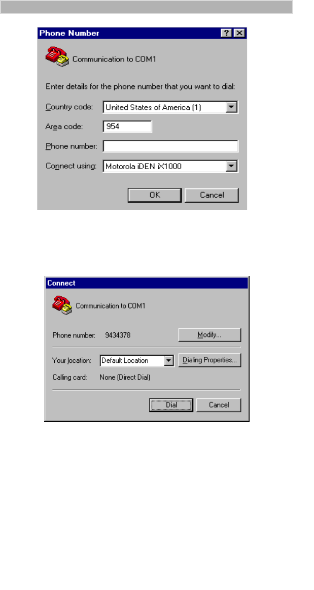
Figure 65. Modem Number Dialog Box
9. In the Connect using field, select the name of the Motorola iDEN
iX1000 modem.
10. Click “OK”. The Connect window opens.
Figure 66. Connect Window
11. Click “Dial”.
12. When your call is complete, click “Yes” to save and close the session or
click “No” to close the session without saving it.
13. When you finish, click “OK”.
iModem/user Page 59 Thursday, October 7, 1999 7:46 PM

60
iM1000 -Data Modem
Configuring the Modem for Packet Data—
without the Disk
If you installed the packet data software on Windows 95, Windows 98, or
Windows NT with the disk, skip this section.
You can configure your modem for iDEN packet data services manually
(that is, without the installation program) for an IBM PC-compatible
computer, an Apple Macintosh computer, or a hand-held computing
device.
Installation Requirements
• An iDEN data modem
• A data cable (PC-compatible or Macintosh)
• An IBM PC-compatible or Macintosh computer, or a hand-held device
with an RS232C serial port
• An active account with your iDEN carrier
• Communication software
If you have been using a wireline modem with your software application,
make sure that the serial (COM) port that you specified in your
communication software is the same port to which the modem is connected.
Installing Dial-Up Networking
This section provides the procedure for setting up Dial-Up Networking on
your Windows 95, Windows 98, or Windows NT computer.
Make sure that your Windows 95, Windows 98, or Windows NT installation
media (CD-ROM or disks) is available. You may be asked to insert the CD-
ROM or floppy disk later in the installation procedure.
1. From the Control Panel, double-click “Add/Remove Programs”. The
Add/Remove Programs Properties window opens.
2. Select the “Windows Setup” tab.
3. Highlight “Communications” in the Components box.
4. Click “Details”. The Communications dialog box opens.
5. In the Communications dialog box:
a. Make sure that the selection box to the left of “Dial Up
Networking” has a check mark in it.
b. Make sure that the selection box to the left of “HyperTerminal”
has a check mark in it.
c. Click “OK” to close the dialog box, then click “OK” again.
6. Restart your computer.
7. Continue with defining your dial-up networking connection.
iModem/user Page 60 Thursday, October 7, 1999 7:46 PM

61
APPENDIX
Establishing Communication
To set up your iDEN modem for packet data services using AT commands,
you must first establish basic communication with the modem.
If you have not connected the data cable to the computer and your modem,
do so now. If you need instructions, see “This section provides information
for connecting the data cable and installing the software.” on page 16.
Software Connections
After you establish the hardware connections, you must run a terminal
software program on your computer. The terminal program provides simple
communication through the computer serial port.
To test the connection,
1. Type ATi4 in the Terminal Window.
2. Press Enter. You should see one of the following messages:
If the Connection Fails
If the message, OK, or the message, 0, does not display when you issue the
AT command, check the connections and try again. Make sure that:
If, after taking the above measures, the connection continues to fail, see
“TROUBLESHOOTING” on page 53.
MOTOROLA, IDEN
OK
- or - MOTOROLA, IDEN
0
√The modem is powered on.
√The cable is connected according to the instructions in
“This section provides information for connecting the data
cable and installing the software.” on page 16.
√The serial (COM) port on the computer, to which the cable
is connected, is the same as the serial port specified in your
communication software.
√The communication program that you are using is listed in
“Configuring Communications Software”page 51.
√The software is configured according to the procedure
described in this section.
iModem/user Page 61 Thursday, October 7, 1999 7:46 PM

62
iM1000 -Data Modem
Configuring Port and Dial Settings
If you are installing data modem on a computer or hand-held device that
does not use Windows 95, Windows 98, or Windows NT, configure your
port and dial settings, as follows:
Baud rate=19200
Data bits=8
Stop bits=1
Parity=None
Duplex=Full
Dial Method=Tone
Flow Control=Hardware
Data Initialization String=AT&K3
If the hardware flow control is not supported, set the Data Initialization
String to AT&K4.
Configuring the Modem with AT Commands
If you are not using the Installation disk, configure your
AT command set using the following guidelines.
Enter the command indicated next to Command Syntax.
Restore Factory Defaults
First, restore the current values to their factory default values. This will
ensure a clean start for the rest of the configuration.
NOTE
DCE refers to your iDEN modem.
DTE refers to your computer or hand-held computing
device.
AT Command Restore Factory-Default Configuration
Command Syntax AT&F
Expected Return Code(s) OK
iModem/user Page 62 Thursday, October 7, 1999 7:46 PM

63
APPENDIX
Activate DTR Monitoring
By factory default, the DCE does not monitor the DTR line of the DTE/
DCE physical connection. Many communications programs use the DTR
line to terminate ongoing PPP/SLIP sessions. Therefore, you must activate
DTR monitoring in the DCE.
Activate DCD Management
By factory default, the wireless modem keeps the Data Carrier Detect
(DCD) line of the computer-to-modem physical connection active at all
times. Some communications programs monitor this line to determine the
status of the connection. To promote compatibility with these programs,
enable DCD management in the modem.
Set the Computer’s IP Address
You must inform the modem of the computer IP address to establish a SLIP
or PPP connection between the modem and the computer. The following
example uses the IP address 170.206.1.1. Substitute this value with the
address supplied by your system administrator or service provider.
AT Command DTR Behavior
Command Syntax AT&D2
Expected Return Code(s) OK
AT Command DCD Behavior
Command Syntax AT&C1
Expected Return Code(s) OK
AT Command Computer IP Address
Command Syntax AT+WPNEI=Ò170.206.1.1.
Expected Return Code(s) OK
iModem/user Page 63 Thursday, October 7, 1999 7:46 PM

64
iM1000 -Data Modem
Select iDEN Packet Wireless Data
The iDEN modem is capable of supporting multiple wireless data formats;
therefore, you must select the desired data service.
Select SLIP or PPP
When iDEN Packet Data services are active, a SLIP or PPP connection is
established between the computer and the modem. (The SLIP/PPP
connection does NOT take place on the over-the-air interface.) By default,
the modem attempts to establish a PPP connection. To establish a SLIP
connection, you must specify this request.
Although the following chart displays the SLIP and the PPP selection
commands, you may skip SLIP if you choose PPP.
Mobile IP Activation
The iDEN Data Implementation makes use of Mobile IP to manage a truly
mobile computer. You may use a Mobile IP stack on the computer or use the
Mobile IP stack built into the modem.
By default, the modem is configured for the mobile IP stack built into it. If
you desire this mode of operation, skip ahead to “Configure Encryption
Settings” on page 66.
Otherwise, you must deactivate the Mobile Node functionality within the
modem.
AT Command Select WDS-side stack
Command Syntax AT+WS46=24
Expected Return Code(s) OK
AT Command Select computer-side stack
Command Syntax PPP AT+WS45=4
SLIP AT+WS45=3
Expected Return Code(s) OK
AT Command Modem Mobile IP Control
Command Syntax Activate AT+WV300=1
Deactivate AT+WV300=0
Expected Return Code(s) OK
iModem/user Page 64 Thursday, October 7, 1999 7:46 PM

65
APPENDIX
Mobile IP Home Agent Address
You must specify the IP address of the Home Agent. The following example
uses the IP address 170.206.50.1 Substitute this value with the address
supplied by your system administrator or service provider.
Mobile IP Authentication Key
The Mobile IP Authentication Key is used as a PIN number to validate your
Mobile IP connection with the Home Agent.
The following example uses the Authentication Key “ABC123”. Substitute
this value with the one supplied by your system administrator or service
provider.
Be sure to place quotation marks around the Authentication Key name.
Mobile IP Security Parameter Index (SPI)
The SPI is similar to the Authentication Key in that the modem and the
Home Agent must have identical values registered for the computer.
The following example uses the SPI 256. Substitute this value with the SPI
supplied by your system administrator or service provider.
AT Command MIP Home Agent Address
Command Syntax AT+WV305=Ò170.206.50.1”
Expected Return Code(s) OK
AT Command MIP Authentication Key
Command Syntax AT+WV301=ÒABC123Ó
Expected Return Code(s) OK
AT Command MIP Security Parameter Index
Command Syntax AT+WV309=256
Expected Return Code(s) OK
iModem/user Page 65 Thursday, October 7, 1999 7:46 PM

66
iM1000 -Data Modem
Mobile Node IP Prefix Length
The prefix length of an IP address is the number of contiguous (adjoining)
bits that make up the network prefix of that IP address. This command sets
the prefix length of the computer’s IP address (see “Set the Computer’s IP
Address” on page 63).
The following example uses the Prefix Length 2. Substitute this value with
the Prefix Length supplied by your system administrator or service provider.
Configure Encryption Settings
Data Encryption allows you to send and receive sensitive information
without allowing others to electronically eavesdrop on your data
transmissions. Although network performance might be adversely affected
by the activation of data encryption, its use is recommended if you are
connecting to secure networks.
Note that this encryption setting is independent of encryption offered by
applications such as Netscape.
Data Encryption is disabled by default.
If you do not want to use the data encryption feature, skip ahead to “Saving
Your AT Settings” on page 67.
If you want to use data encryption, you must specify the request as
negotiable or not negotiable.
• If the encryption request is not negotiable and the network is not able to
grant the request (for whatever reason) for encryption, your connection
will be terminated.
• If the encryption request is negotiable and encryption is not available in
the network, the connection will be maintained in a non-encrypted state.
You also have the option to specify an Encryption Key Size.
The following example uses the Encryption Key Size 40. You can substitute
this value with any value within the allowed range of 40 to 64.
AT Command Mobile Node IP Prefix Length
Command Syntax AT+WV311=2
Expected Return Code(s) OK
AT Command Network Air-Link Encryption
Command
Syntax No Encryption AT+WV308=0,0,40
Negotiable AT+WV308=1,0,40
Not Negotiable AT+WV308=1,1,40
Expected
Return Code(s) OK
iModem/user Page 66 Thursday, October 7, 1999 7:46 PM

67
APPENDIX
Header Compression
Use this command to disable header compression.
Saving Your AT Settings
Your modem is now properly set up for typical iDEN Wireless Data
Services use. These settings, however, are stored only in the modem’s
Random Access Memory (RAM). If the modem is turned off, the settings
will be lost. The next step, then, is to save the settings in the modem’s non-
volatile memory.
Like many other modems, the iDEN modem is capable of storing more than
one personality, or image, into non-volatile memory. Each image can then
be read, altered, and saved without changing the contents of the others. The
iDEN modem has three images.
By default, the third image is loaded when the modem is powered on or
when the data cable is unplugged. It might seem logical to store these
settings into this first profile. However, because many communication
programs alter the contents of this first image, some of your parameters
might be overwritten. For this reason, store these parameters in the second
image.
By convention, the first image is named User Image 0, the second image is
User Image 1, and the third image is User Image 2.
+WS182
This command enables or disables TCP header
compression options. Some DTE-Side Stacks (such as
PPP) will negotiate local header compression
independently from this setting.
Action AT+ws182=<header compression>
Query AT+ws182?
Range AT+ws182=?
Parameter Values:
0 Over-the-air and local header
compression enabled
1 Over-the-air header compression enabled
2 Local header compression enabled
3 Header compression disabled
AT Command Save User Default Configuration
Command Syntax AT&W1
Expected Return Code(s) OK
iModem/user Page 67 Thursday, October 7, 1999 7:46 PM

68
iM1000 -Data Modem
Troubleshooting Diagnostic Commands
If a data connection could not be established, you might be able to
determine the cause through the AT command interface.
Follow the steps listed below:
• Close all data applications.
Otherwise, these applications might start a retry command that will
interrupt your troubleshooting efforts.
• Unplug and re-connect the data cable.
This terminates any ongoing data connections.
• Establish basic computer-to-modem communication.
For instructions, see “Establishing Communication” on page 61.
• Query the last “Extended Error Code”.
Although you might not be able to see the text as you type it, you should
see a result code returned to you.
Extended Error Result Codes
Extended error result codes report the network reason why a data
connection failed. If you report a failed connection to technical support, be
sure to provide the code. See the following table for a list of the extended
error result codes that the modem can return.
AT Command Return Product Information
Command Syntax AT+CEER
Expected Return Code(s) See Below
Table 5: Extended Error Result Codes
Code Description
General Modem Operation
257 No further information is available.
259 A command was issued during an improper state
(Command/Online).
260 The connection was aborted by the user.
261 The DCE does not recognize an AT Command.
262 The connection was aborted due to a connection timeout.
263 The parameters for an AT Command are out of range.
266 The +FCLASS command failed due to incompatibilities
with the current setting of the +WS46 command.
iModem/user Page 68 Thursday, October 7, 1999 7:46 PM

69
APPENDIX
267 The +WS45 command failed due to incompatibilities with
the value of the +WS46 command.
268 Invalid DTE-IP address was specified (+WPNEI).
269 Invalid Home Agent Address was specified (+WV305).
270 Invalid MIP Security Parameter Index was specified.
(+WV309).
271 DCE IP address matched Home Agent IP Address
(+WV304, +WV305).
272 The DTE tried to lock or unlock the DCE using an
incorrect PIN.
275 An AT Command is not compatible with the currently
active data service.
Packet Data Operation
519 Requested level of encryption is not allowed.
545 Service is not present.
612 A data registration error was found. Contact your Service
Provider.
833 FA: Mobile Node Administratively is prohibited from
registration.
835 FA: Mobile Node Authentication failed.
836 FA: Home Agent Authentication failed.
897 HA: Mobile Node Administratively is prohibited from
registration.
899 HA: Mobile Node Authentication failed.
900 HA: Foreign Agent Authentication failed.
1025 SLIP/PPP failed to respond.
1026 SLIP/PPP failed to configure the connection.
1027 SLIP/PPP link terminated.
Table 5: Extended Error Result Codes
Code Description
iModem/user Page 69 Thursday, October 7, 1999 7:46 PM

70
iM1000 -Data Modem
Circuit Data Operation
1280 No information is available.
1290 Unspecified Transmit Phase A Error
1300 Unspecified Transmit Phase B Error
1320 Unspecified Transmit Phase C Error
1330 Unspecified Transmit Phase D Error
1350 Unspecified Receive Phase B Error
1360 Unspecified Receive Phase C Error
1370 Unspecified Receive Phase D Error
Network Error Codes
1538 No route to specified transit network.
1539 No route to destination.
1553 Called unit is busy.
1563 Destination is out of order.
1564 Invalid number format - incomplete
1570 No circuit/channel is available.
1574 Network is out of order.
1577 Temporary failure
1578 Switching equipment congestion
1580 Requested circuit/channel is not available.
1583 Resource is unavailable.
1594 Bearer capability is not presently available.
1593 Bearer capability is not authorized.
1599 Service or option is not available.
1601 Bearer service is not implemented.
Table 5: Extended Error Result Codes
Code Description
iModem/user Page 70 Thursday, October 7, 1999 7:46 PM

71
APPENDIX
1602 Channel type is not implemented.
1615 Service or option is not implemented.
1624 Incompatible destination.
Table 5: Extended Error Result Codes
Code Description
iModem/user Page 71 Thursday, October 7, 1999 7:46 PM

72
iM1000 -Data Modem
Commonly Used AT Commands
The subset of AT commands supported by iDEN Wireless Data Services is
provided in this section for your reference.
These commands must be preceded by the command line prefix “AT”, for
example, “ATa”.
To enter commands, you can use upper- or lower-case letters, or both.
Answer
Command Mode Echo
NOTE
DCE refers to your iDEN modem.
DTE refers to your computer or hand-held device.
A
If an incoming (decoded) data service is pending, this
command instructs the DCE to immediately connect to the call
and start the answer sequence, as appropriate for the selected
service.
Action ATa
Query
Range
E
The setting of this parameter determines whether or not the
DCE echoes characters received from the DTE during
command state and online command state.
Action ATe <echo>
Query AT&v
Range
Parameter Values:
0 Disable command mode character echo.
1 Enable command mode character echo.
iModem/user Page 72 Thursday, October 7, 1999 7:46 PM

73
APPENDIX
Dial
Hangup
D
This command instructs the DCE to originate a call.
When the DCE receives the dial string from the computer, all
non-numeric characters in the Dial String that are not
recognized dial-modifiers are ignored. This allows the DTE to
request modem numbers containing unsupported dial
modifiers, hyphens, parenthesis, and other punctuation.
Action ATd <Dial String>
Query
Range
Parameter Values:
Dial String contains a modem number to be dialed, translated
into an array of ASCII characters between 0 and 9 inclusive.
Dial Modifiers:
T Allowed, but ignored by the modem.
P Allowed, but ignored by the modem.
! Hook Flash (1/2 second).
W Wait for time specified in S7 for dial tone.
Wait for time specified in S7 for one or more
rings followed by five seconds of silence before
continuing execution of dial string.
, Pause for time specified in S8.
; After dialing return to command mode.
H
This command instructs the modem to terminate the active
call.
Action ATh
Query
Range
iModem/user Page 73 Thursday, October 7, 1999 7:46 PM

74
iM1000 -Data Modem
Request Modem Information
Go Online
Pulse Dialing
I
This command causes the modem to issue a string to provide
product information.
Action ATi<request>
Query
Range
Parameter Values:
0 OK Response code
1 iDEN DTE/DCE Specification Version
2 Software Model
3 Product model
4 Product manufacturer
O
This command causes the modem to enter the online state
from the online command state.
Action ATo
Query
Range
P
This command selects pulse dialing. It is provided for
compatibility purposes.
Action ATp
Query
Range
iModem/user Page 74 Thursday, October 7, 1999 7:46 PM

75
APPENDIX
Quiet Mode
Tone Dialing
Verbose Result Codes
Q
This command controls whether or not result codes are sent to
the computer. If Quiet Mode is turned off, the result codes may
be further modified by the Result Code Format and Extended
Result Codes commands.
Action ATq<setting>
Query AT&v
Range
Parameter Values:
0 Result codes sent
1 Result codes not sent
T
This command selects DTMF dialing. It is provided for
compatibility purposes.
Action ATt
Query
Range
V
This command sets your preference for result code format. It
allows the computer to select Terse or Verbose result codes.
Action ATv<setting>
Query AT&v
Range
Parameter Values:
0 Numeric result code format
1 Verbose result code format
iModem/user Page 75 Thursday, October 7, 1999 7:46 PM

76
iM1000 -Data Modem
Extended Result Codes
Restore User Defaults
X
This command provides an extended result code selection.
Action ATx<setting>
Query AT&v
Range
Parameter Values:
0,1 The modem does not return the BUSY or NO
DIALTONE result codes.
2 The modem might return the NO DIALTONE result
code if appropriate, but does not return the BUSY
result code.
3 The modem may return the BUSY result code if
appropriate, but does not return the NO DIALTONE
result code.
4 The modem may return either the BUSY or NO
DIALTONE result code, if appropriate.
Z
This command causes the modem to reset all parameters and
S-registers to their user-defined default values. There are three
sets of user defaults. The parameter selects between which set
(or image) is being requested.
Action ATz<image>
Query
Range
Parameter Values:
0 Load user image 0
1 Load user image 1
2 Load user image 2
iModem/user Page 76 Thursday, October 7, 1999 7:46 PM

77
APPENDIX
DCD Behavior
DTR Behavior
&C
This parameter determines how the DCD line (circuit 109)
relates to the detection of received line signals from the distant
end. Changing the parameter takes effect immediately in both
the command and online command states.
Action AT&c<setting>
Query AT&v
Range
Parameter Values:
0 DCD always on
1 The modem turns on the DCD to indicate the
presence of a connection, and turns off the DCD
to indicate the loss of a connection.
&D
This parameter determines how the computer responds when
the DTR line (circuit 108/2) is changed from the “onÓ condition
to the “offÓ condition during the online data state.
Action AT&d<setting>
Query AT&v
Range
Parameter Values:
0 Modem ignores DTR
1 If the DTR is turned on while in online data
mode, the modem returns to command mode
and issues the OK result code. The call remains
connected.
2 If the DTR is turned off while in online data
mode, the modem disconnects the call and
returns the OK result code. If DTR is off while in
command mode, the modem will not answer an
incoming call, regardless of the setting, S0
(Automatic Answer).
iModem/user Page 77 Thursday, October 7, 1999 7:46 PM

78
iM1000 -Data Modem
Restore Factory Defaults
Local Flow Control (Traditional)
Display Current Parameter Values
&F
This command causes the modem to reset all parameters and
S-registers to their factory-defined default values. The optional
parameter value, if present, must be 0.
Action AT&f
Query
Range
&K
This parameter selects the type of flow control used between
the computer and the modem while in data transfer mode. This
command is supported for backwards compatibility purposes.
This command sets the method of flow control for both
directions of the computer-to-modem interface, while the +IFC
command allows for a separate setting for each direction. The
setting of this command may implicitly alter the settings of the
+IFC command.
Action AT&k<setting>
Query
Range
Parameter Values:
0 No Flow Control (not recommended).
3 RTS/CTS Flow Control
4 XON/XOFF Flow Control
&V
This command allows the computer to view the parameter and
S-register settings for the active configuration profile.
Action AT&v
Query
Range
iModem/user Page 78 Thursday, October 7, 1999 7:46 PM

79
APPENDIX
Local Character Framing
+ICF
This parameter determines the local serial port asynchronous
data framing. The second parameter is needed only if you
select less than eight data bits.
Action AT+icf=<Framing>[,<Parity>]
Query AT+icf?
Range AT+icf=?
Parameter Values:
Framing
0 AutoDetect
3 8 data bits, 1 stop bit
5 7 data bits, 1 parity bit, 1 stop bit
Parity
0 Odd
1Even
2 Mark
3 Space
iModem/user Page 79 Thursday, October 7, 1999 7:46 PM

80
iM1000 -Data Modem
Local Flow Control (PCCA)
+IFC
This extended compound parameter controls the local flow
control between the computer and the modem. The two
numeric subparameters are DCE_by_DTE (which controls the
data from the modem) and DTE_by_DCE (which controls the
data from the computer).
To change the settings of these parameters, use the &K
command.
Action AT+ifc=<DCE_by_DTE>,<DTE_by_DCE>
Query AT+ifc?
Range AT+ifc=?
Parameter Values:
DCE_by_DTE
0 No flow control was set by DTE.
1 XON/XOFF; Do not pass XON/XOFF
characters to the remote DCE.
2 RFR active/inactive flow control
3 XON/XOFF; Pass DC1/DC3 characters to the
remote DCE in addition to acting upon local
flow control.
DTE_by_DCE
0 No flow control was set by DTE.
1 XON/XOFF flow control
2 CTS/RFS active/inactive flow control
iModem/user Page 80 Thursday, October 7, 1999 7:46 PM
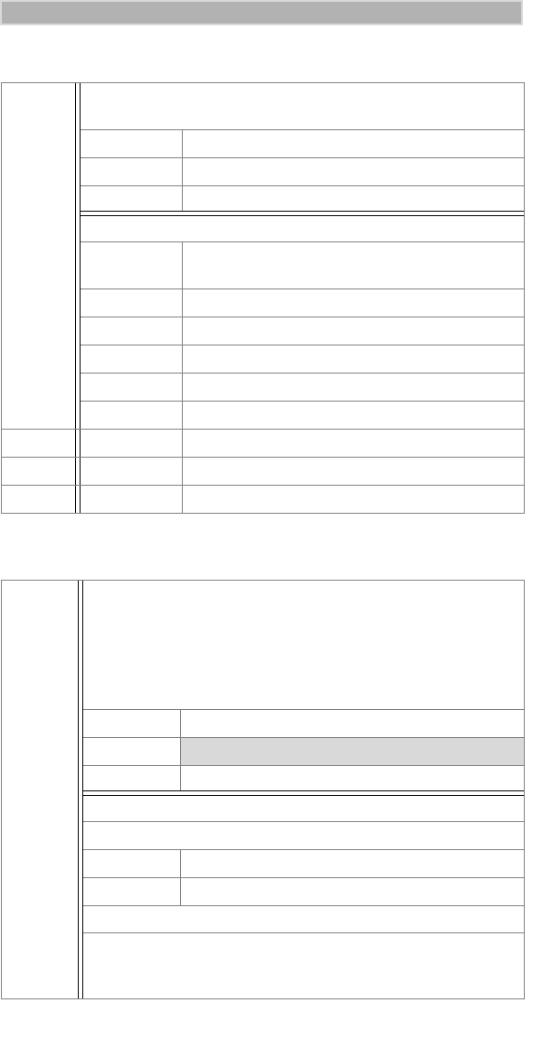
81
APPENDIX
Local Data Rate
Lock/Unlock the DCE
+IPR
This numeric extended-format parameter specifies the data
rate between the DTE and the DCE.
Action AT+ipr=<rate>
Query AT+ipr?
Range AT+ipr=?
Parameter Values:
0 Automatic detection on baud rate, data
framing
300 Transmission speed in bits per second.
2400 Transmission speed in bits per second.
4800 Transmission speed in bits per second.
9600 Transmission speed in bits per second.
19200 Transmission speed in bits per second.
38400 Transmission speed in bits per second.
57600 Transmission speed in bits per second.
115200 Transmission speed in bits per second.
+WCLK
When the DCE is locked, most communication over the
serial port to the modem is suspended until the DCE is
unlocked.
If the PIN was removed (by setting its value to the empty
string (ÒÓ), the DTE must still specify the PIN, represented
by the empty string.
Action AT+wclk=<LockStatus>,<PIN>
Query
Range AT+wclk=?
Parameter Values:
Lock Status
0 Unlock the DCE
1 Lock the DCE
PIN
A PIN is stored as a series of alphanumeric characters, with
a maximum length of 8 characters. If more than 8
characters are set as a PIN, only the first 8 are recognized.
iModem/user Page 81 Thursday, October 7, 1999 7:46 PM

82
iM1000 -Data Modem
Change the DCE’s PIN
Packet Data Sleep Timer
SLIP MTU
+WCPN
This command sets the PIN that locks or unlocks the DCE.
Note that you must specify the desired PIN, as well as the
current PIN. The factory-default PIN is the Òempty stringÓ,
or a value of ÒÓ.
Action AT+wcpn=<newPIN>,<oldPIN>
Query
Range AT+wcpn=?
Parameter Values:
A PIN is stored as a series of alphanumeric characters, with
a maximum length of 8 characters. If more than 8
characters are set as a PIN, only the first 8 are recognized.
+WS175
This timer controls the length of time the DCE stays on a
packet channel while there is no traffic actively being
transferred.
Action AT+ws175=<timer>
Query AT+ws175?
Range AT+ws175=?
Parameter Values:
0 Disable sleep timer
5-255 Seconds before sleeping
10 Default value
+WV312
This setting specifies the Maximum Transmitted Unit used
by SLIP connections. (PPP connections negotiate this
value.)
Action AT+wv312=<MTU>
Query AT+wv312?
Range AT+wv312=?
Parameter Values:
68-1500 MTU Value Range
1006 Default value
iModem/user Page 82 Thursday, October 7, 1999 7:46 PM
83
APPENDIX
Select Mobile IP Client
Mobile IP Authentication Key
+WV300
This parameter activates/deactivates the Mobile Node
client in the DCE. The mobile host can operate in two
modes to access the iDEN packet data network.
Action AT+wv300=<MIP Mode>
Query AT+wv300?
Range AT+wv300=?
Parameter Values:
0 Deactivate Mobile Node in DCE
1 Activate Mobile Node in DCE
+WV301
The iDEN network uses the MIP Authentication Key to
verify the authenticity of the DCE with the Home Agent. The
DCE and the Home Agent must have identical values for
this shared secret key for the DCE to satisfy the
authentication process.
NOTE: This command is applicable only when the Mobile
Node Client in the DCE is Activated.
Action AT+wv301=<ÒkeyÓ>
Query
Range AT+wv301=?
Parameter Values:
The Authentication Key parameter is a text string of up to
32 characters. Unlike most text-string parameters, the
Authentication Key is a text representation of a
hexadecimal number. Therefore, only the characters 0-9
and A-F are acceptable. (The lower case characters, a-f,
are also acceptable).
Note that although this parameter represents a numeric
value, the parameter is actually a text string, so the
parameter must be enclosed in quotation marks.
iModem/user Page 83 Thursday, October 7, 1999 7:46 PM

84
iM1000 -Data Modem
Mobile IP Session Timer
DTE IP Address
+WV302
This command determines the maximum amount of time
that a remote node can be registered with its Home Agent
before having to renew its registration. This parameter sets
a user preference for a value that is negotiated within the
network. During the negotiation process, the user
preference may be overruled by the network without
notification.
Action AT+wv302=<timer>
Query AT+wv302?
Range AT+wv302=?
Parameter Values:
1800-65534 Seconds before expiration
65535 Timer never expires
7200 Default value
+WPNEI
This command sets the mobile node’s permanent IP
Address (also known as the Network Entity Identified, or
NEI).
NOTE: This parameter is applicable only when the Mobile
Node Client in the DCE is Activated.
Action AT+wpnei=<ÒaddressÓ>
Query AT+wpnei?
Range AT+wpnei=?
Parameter Values:
An IP address consists of up to 15 characters, and is in the
format Òddd.ddd.ddd.dddÓ.
0.0.0.0 Default value
iModem/user Page 84 Thursday, October 7, 1999 7:46 PM

85
APPENDIX
DTE IP Address Prefix Length
Data Encryption
+WV311
The Prefix-Length is the number of contiguous bits in an IP
address that makes up the network prefix (or network
number plus subnet number) of that IP address.
This command sets the Prefix Length of the Mobile Node’s
IP address, as specified by +WPNEI.
Action AT+wv311=<length>
Query AT+wv311?
Range AT+wv311=?
Parameter Values:
2-24 Prefix length
2 Default value
+WV308
The DTE uses this command to select whether or not to
encrypt the air-link interface and also how the air-link is
encrypted. Encryption is negotiated during packet data
registration.
Action AT+wv308=<encryption>,<firm offer>,<key
size>
Query AT+wv308?
Range AT+wv308=?
Parameter Values:
Encryption
0 Disabled
1 Vancouver Encryption
Firm Offer
0 Encryption setting is a negotiable
preference
1 Encryption setting is not negotiable
Key Size
40-64 Encryption Key Size
40 Default value
iModem/user Page 85 Thursday, October 7, 1999 7:46 PM

86
iM1000 -Data Modem
DTE Stack
WDS Stack
+WS45
This command sets the protocol for communication
between the DCE and the DTE. Circuit-switched data
connections allow only the transparent character stream.
For packet data connections, use SLIP or CSLIP or PPP.
Action AT+ws45=<stack>
Query AT+ws45?
Range AT+ws45=?
Parameter Values:
0 Transparent Character Stream
1 Reliable Transparent Character Stream
(TMDL)
3 SLIP/CSLIP
4 PPP
+WS46
This command changes the data mode of the modem
between circuit-switched data and packet data.
Action AT+ws46=<service>
Query AT+ws46?
Range AT+ws46=?
Parameter Values:
23 iDEN circuit-switched data/fax
24 iDEN packet data
252 Local Data Services
iModem/user Page 86 Thursday, October 7, 1999 7:46 PM

87
APPENDIX
Service Class
Packet Data Registration Timeout
Circuit Data Auto-Answer
+FCLASS
This command switches between normal circuit-switched
data mode and Class 2 fax mode. This setting has no effect
during packet data service.
Action AT+fclass=<class>
Query AT+fclass?
Range AT+fclass=?
Parameter Values:
0 Class 0 operation (modem operation)
2 Class 2 operation (fax operation)
8 Class 8 (voice operation - while tethered)
+WS198
This command allows the DTE to specify a maximum
amount of time to wait for packet data registration.
Action AT+ws198=<time>
Query AT+ws198?
Range AT+ws198=?
Parameter Values:
1-255 Seconds
30 Default value
S0
This command determines if and when the DCE should
automatically answer an incoming call.
Action ATs0=<rings>
Query ATs0?
Range ATs0=?
Parameter Values:
0 Do not automatically answer incoming
calls.
1-255 Answer after specified number of rings.
iModem/user Page 87 Thursday, October 7, 1999 7:46 PM

88
iM1000 -Data Modem
Circuit Data Establishment Timeout
Comma Dial Modifier Timer
Circuit Data Idle Timer
S7
This command allows the DTE to specify the maximum
amount of time between a request for a circuit data
connection and the establishment of this connection.
Action ATs7=<timer>
Query ATs7?
Range ATs7=?
Parameter Values:
1-255 Seconds
120 Default value
S8
This command allows the DTE to set the duration of the
pause associated with a comma (,) dial modifier.
Action ATs8=<timer>
Query ATs8?
Range ATs8=?
Parameter Values:
0-255 Seconds
2 Default value
S30
This command specifies an idle line timeout for online data
mode. If no data is sent by the DTE on the transmit data line
for the specified period of time, the DCE disconnects the
call, returns the OK result code, and returns to command
mode.
Action ATs30=<timer>
Query ATs30?
Range ATs30=?
Parameter Values:
0-255 Seconds
0 Default value
iModem/user Page 88 Thursday, October 7, 1999 7:46 PM

89
APPENDIX
AT Command Subset for Fax Operation
Your modem also supports a subset of the standard action command and
response set commonly used in fax operation. Your communication software
or specialized fax software uses these commands during regular fax
operation.
If you issue an unsupported command, the modem displays the message,
ERROR.
See the following list of fax commands.
Table 6: AT Command Subset for Fax Operation
Command Function
+FDT Transmit data. The optional sub-parameters DF,
VR, WD and LN are not allowed.
If you use any of
them, your modem displays the message,
ERROR
.
• Polled transmission is NOT supported (that is,
the +FLPL parameter cannot be set to 1).
• Block mode and ECM operation are NOT
supported, that is, the +FTBC and +FECM
parameters cannot be set to any number other
than 0 (zero).
+FDR Receive data.
• Polled reception is NOT supported (that is, the
+FLPL parameter cannot be set to 1).
• Block mode and ECM operation are NOT
supported, that is, the +FTBC and +FECM
parameters cannot be set to any number other
than 0 (zero).
+FET Transmit Page Punctuation.
• Another Page Next/Same Document, when
followed by 0 (zero).
• No More Pages or Documents, when followed by
2.
Any other value causes the modem to display the
message, ERROR.
+FK Terminates current fax session.
iModem/user Page 89 Thursday, October 7, 1999 7:46 PM

90
iM1000 -Data Modem
S-Registers
S-registers are memory locations in the modem that you can program to suit
your data communication needs. For instance, you can set up the modem to
automatically answer all incoming data calls.
S-registers are numbered from 0 (zero) to 255 (that is, S0 to S255). Since
many of these registers are reserved for purposes of internal operation, you
may customize only a subset of the modem’s registers.
To see the list of S-Registers that you may customize, see “Customizing S-
Registers” on page 91.
Programming an S-Register
To program an S-register:
1. Go to the command mode of your communication software.
2. Type ATSn=x where n is the number of the S-register that you want to
customize; and x is the value that you want to assign to that register.
For example, to set up your modem to automatically answer all
incoming data calls, type ATS0=x (where x is any number between 1
and 255).
3. Press Enter.
NOTES
• You might experience undesirable consequences on
the operation of the remote modem if you modify the S7
or S10 registers from their default values. For optimal
performance, use the default values for these two
registers.
• If you write to an S-register that is not programmable or
if the value that you assigned to a register is invalid, the
modem will still return an OK message on the computer
screen. But, this will have no effect on S-register values.
iModem/user Page 90 Thursday, October 7, 1999 7:46 PM

91
APPENDIX
Reading the Value of an S-Register
You may also want to read the value of a particular S-register.
For a list of supported S-registers, see Table 7 on page 91.
To read the value of an S-register:
1. Bring up the command mode of your communication software.
2. Type ATSn where n is the number of the S-register that you want to
read from the software’s command mode.
For example, to read the value of S-register number 0 (zero), you
would type ATS0?.
3. Press Enter. The value of the requested S-register displays.
4. If you attempt to read the value of an S-register that is not supported,
the modem displays the message, ERROR.
You can also read S-register values in bulk by issuing an AT&V command.
Customizing S-Registers
You can use the following list of S-registers to customize the modem’s data
operation.
Table 7: Supported S-Registers
Register # Function
0Automatic Answer. Determines if the modem
automatically answers an incoming call.
• If the value assigned to this register is 0 (zero), the
modem does not answer the call, but sends an
appropriate message to the computer that
commands the modem to answer the call.
• If the value assigned to this register is non-zero, the
modem answers the call without waiting for the
computer to issue its answer-call command.
The valid range of values is 0 (zero) to 255. The
default is 0 (zero).
2Escape Code Character. Specifies the ASCII
character to be used to escape from either data or
online mode to command mode.
The valid range of values is 0 (zero) to 127. The
default is 43 or the ASCII plus (+) key.
iModem/user Page 91 Thursday, October 7, 1999 7:46 PM

92
iM1000 -Data Modem
3Command Line Terminating Character. Specifies the
ASCII character to be used to terminate a command
line without carrying out any command that might be
issued.
The valid range of values is 0 (zero) to 127. The
default is 13, which represents the Enter (PC-
compatible) or Return (Macintosh) key.
4Response Format Character.
The valid range of values is 0 (zero) to 127. The
default is 10 or the ASCII ÒLinefeedÓ character.
5Command Line Editing Character.
The valid range of values is 0 (zero) to 127. The
default is 8 or the Backspace key.
6Pause Before Blind Dialing.
The valid range of values is 2 to 10. The default is 2,
or 2 seconds.
7Connection Completion Timeout.
The valid range of values is 1 to 255 seconds. The
default is 120 seconds.
8Command Dial Modifier Time.
The valid range of values is 0 (zero) to 255 seconds.
The default is 2 seconds.
10 Automatic Disconnect Delay. Determines the amount
of time between loss of carrier and disconnection of
the data call.
The valid range of values is 1 to 254 tenths of a
second. The default is 14, or 1.4 seconds.
12 Escape Code Timer. Determines the time duration
within which the escape code must be sent by the
computer to escape from online mode to command
mode.
The valid range of values is 20 to 255. The time (in
seconds) that the modem waits is determined by
dividing the specified register value by 50. The default
is 50 (that is, 50/50) or 1 second.
Table 7: Supported S-Registers
Register # Function
iModem/user Page 92 Thursday, October 7, 1999 7:46 PM

93
APPENDIX
30 Idle Timeout. Determines the amount of time that the
modem waits in online mode for a command from the
computer before disconnecting the call and returning
to command mode.
The valid range of values is 0 (zero) to 255 seconds.
The default is 0 (zero) seconds or an infinite time
period.
Table 7: Supported S-Registers
Register # Function
iModem/user Page 93 Thursday, October 7, 1999 7:46 PM

94
iM1000 -Data Modem
For the Safe and Efficient Operation of Your Radio,
Observe These Guidelines:
Your radio product contains a transmitter and a receiver. When it is ON,
it receives and transmits radio frequency (RF) energy. The radio
operates in the frequency range of 806 MHz to 866 MHz and employs
digital modulation techniques. This product is authorized under FCC
Rule Part 47CFR 2. 1091 (b), which states that it should be used in such
a way that a separation distance of at least 8 inches (20 cms) is normally
maintained between the radio’s antenna and the body of the user or
nearby persons. When you use your radio product, the system handling
your call, controls the power level at which your radio product
transmits. The output power level typically may vary over a range from
0.0024 watts to 0.7 watts.
Exposure To Radio Frequency Energy
Your Motorola Radio Product is designed to comply with the following
national and international standards and guidelines regarding exposure
of human beings to radio frequency electromagnetic energy:
• United States Federal Communications Commission, Code of
Federal Regulations; 47 CFR part 2 sub-part J
• American National Standards Institute (ANSI) IEEE. C95. 1-1992
• National Council on Radiation Protection and Measurements
(NCRP). Report 86
• International Commission on Non-Ionizing Radiation Protection
(ICNIRP) 1998
• European Committee for Electrotechnical Standardization
(CENELEC), ENV 50166-2, 1995 E
• National Radiological Protection Board of the United Kingdom,
GS 11, 1988
• Verband Deutscher Elektrotechniker (VDE) DIN-0848
• Department of Health and Welfare Canada. Safety Code 6
SAFETY AND GENERAL
INFORMATION
IMPORTANT INFORMATION ON SAFE AND
EFFICIENT OPERATION.
READ THIS INFORMATION BEFORE USING YOUR
INTEGRATED MULTI-SERVICE RADIO PRODUCT.
iModem/user Page 94 Thursday, October 7, 1999 7:46 PM

95
SAFETY AND GENERAL INFORMATION
Antenna and Installation Considerations
• All equipment must be properly installed in accordance with
Motorola installation instructions.
• To assure compliance with United States FCC regulations on RF
exposure, the user of the equipment must position the antenna in
such a way to maintain a separation of at least 8 inches (20 cms)
between the antenna and the body of any user and nearby person.
• Ensure that the antenna is properly installed external to the vehicle
and in accordance with the requirements of the antenna
manufacturer/supplier.
• Use only the supplied or an approved antenna. Unauthorized
antennas, modifications, or attachments could impair call quality,
damage the modem, or result in violation of the ICNRP or the FCC.
Interference to Medical and Personal Electronic Devices
Most electronic equipment is shielded from RF energy. However,
certain equipment may not be shielded against the RF signals from your
radio product.
Pacemakers
Do not operate the radio when any person is within 6 inches (0.15
meters) of the antenna. That person may be using a pacemaker, a
hearing aid or other personal electronic device which may not be
adequately shielded.
Hearing Aids
Some radio products may interfere with some hearing aids. In the event
of such interference, you may want to consult your hearing aid
manufacturer to discuss alternatives.
Other Medical Devices
If you use any other personal medical device, consult the manufacturer
of your device to determine if it is adequately shielded from external RF
energy. Your physician may be able to assist you in obtaining this
information.
Interference to Other Electronic Devices
RF energy may affect improperly installed or inadequately shielded
electronic operating and entertainment systems in motor vehicles.
Check with the manufacturer or representative to determine if these
systems are adequately shielded from external RF energy. Also check
with the manufacturer of any equipment that has been added to the
vehicle.
iModem/user Page 95 Thursday, October 7, 1999 7:46 PM

96
iM1000 -Data Modem
Safety and General
Use While Driving
Check the laws and regulations on the use of radio products in the area
where you drive. Always obey them.
When using the radio product while driving, please:
• Give full attention to driving and to the road
• Pull off the road and park before using the product if driving
conditions so require.
OPERATIONAL
WARNINGS
POTENTIALLY EXPLOSIVE ATMOSPHERES
Turn off your radio product when you are in any area with a
potentially explosive atmosphere, unless it is a radio product type
especially qualified for use in such areas (for example, Factory
Mutual Approved). Sparks in a potentially explosive atmosphere
can cause an explosion or fire resulting in bodily injury, or even
death.
Note: The areas with potentially explosive atmospheres referred to
above include fueling areas such as: below decks on boats; fuel or
chemical transfer or storage facilities; areas where the air contains
chemicals or particles such as grain, dust or metal powders; and
any other area where you would normally be advised to turn off
your vehicle engine. Areas with potentially explosive atmospheres
are often, but not always posted.
Do not transport or store flammable gas, liquid, or explosives in the
compartment of your vehicle which contains your radio or
accessories.
In the United States, Vehicles powered by liquefied petroleum gas
(such as propane or butane) must comply with the National Fire
Protection Standard (NFPA-58). For a copy of this standard, contact
the National Fire Protection Association. One Batterymarch Park,
Quincy, MA 02269, Attn: Publications Sales Division.
!
W A R N I N G
!
iModem/user Page 96 Thursday, October 7, 1999 7:46 PM

97
OPERATIONAL
WARNINGS
BLASTING CAPS AND AREAS
To avoid possible interference with blasting operations, turn off
your radio product when you are near electrical blasting caps, in
a blasting area, or in areas posted: "Turn off two-way radio".
Obey all signs and instructions.
FOR VEHICLES EQUIPPED WITH AN AIR BAG
An air bag inflates with great force. DO NOT place objects,
including communication equipment, in the area over the air bag
or in the air bag deployment area. If the communication
equipment is improperly installed and the air bag inflates, this
could cause serious injury.
Installation of vehicle communication equipment should be
performed by a professional installer/technician qualified in the
requirements for such installations. An air bag’s size, shape, and
deployment area can vary by vehicle make, model, and front
compartment configuration (for example, bench seat vs. bucket
seats).
Contact the vehicle manufacturer’s corporate headquarters, if
necessary, for specific air bag information for the vehicle make,
model, and front compartment configuration involved in your
communication equipment installation.
!
W A R N I N G
!
iModem/user Page 97 Thursday, October 7, 1999 7:46 PM

98
iM1000 -Data Modem
Cleaning Instructions
Clean the external surfaces of the radio product with a damp cloth, using
a mild solution of dishwashing detergent and water. Some household
cleaners may contain chemicals that could seriously damage the radio
product. Avoid the use of any petroleum-based solvent cleaners. Also,
avoid applying liquids directly on the radio product.
OPERATIONAL CAUTIONS
DAMAGED ANTENNAS
Do not use any radio product with a damaged antenna. If a
damaged antenna comes into contact with your skin, a minor
burn can result.
!
C a u t i o n
iModem/user Page 98 Thursday, October 7, 1999 7:46 PM

99
GLOSSARY
GLOSSARY
asynchronous Data without an accompanying time signal.
Timing is built into data characters as start
and stop bits.
AT command An order entered into the computer to request
your modem to perform certain actions, such
as dial a telemodem number. AT commands
are Hayes-compatible modem commands.
baud rate Signaling speed of the modem. Common
baud rates are 2400, 4800, 9600, 19200, and
38400.
bps Bits per second. The rate at which data passes
over the telephone line or through the air. The
basic unit of measure for serial data
transmission capacity.
burst A unit of information consisting of a sequence
of signals.
circuit-switched data Continuous data communication, such as a
modem call.
CTS The Clear to Send signal passed from the
local modem to the local terminal when the
data port is ready to transmit data. Occurs in
response to the Request To Send (RTS) signal.
command mode The mode that accepts AT commands. Also
known as Terminal Mode. When your modem
is in this mode, it is waiting to receive AT
commands that you type from your
communication software.
communication
software A computer program designed to connect
your computer to an external source, such as
another computer or a fax machine.
iModem/user Page 99 Thursday, October 7, 1999 7:46 PM

100
iM1000 -Data Modem
data services One of the functions of your iDEN modem.
Wireless data services uses both circuit-
switched and packet data transmissions.
DCD Data Carrier Detect. An acceptable carrier
signal received by the modem over the
modem line. Also known as Received Line
Signal Indicator (RLSI).
DCE Data Communications Equipment. The
equipment that establishes, maintains and
terminates a connection. It converts data into
units of sound and vice versa for
communication over telephone or cellular
networks.
default A factory preset choice that, under normal
circumstances, works best for your system.
You can either accept the default or change it.
dialing directory A modem book of frequently called modem
numbers that you can set up and maintain in
your communication software.
DTE Data Terminal Equipment. A computer or
hand-held device that generates and receives
data, and provides functions that control data
communications through a device like the
modem.
hand-held devices Small computing appliances, such as palm
tops, personal digital assistants, and pen-
based computers.
home agent The server that is responsible for routing data
from your home network to your computer.
iDEN carrier Provider of packet data services.
Internet Inter-connected networks that all use the
TCP/IP protocols.
Intranet A private network inside a company or
organization.
iModem/user Page 100 Thursday, October 7, 1999 7:46 PM

101
GLOSSARY
laptops Portable computers, such as notebooks and
subnotebooks.
mobile IP Mobile Internet Protocol—a locating device.
Provides the capability to locate you on the
network at all times.
modem MOdulator/DEModulator. An electronic
device enabling digital data to be sent over
analog transmission facilities. Converts a
digital signal to analog and back to digital
again.
non-volatile memory Permanently stored information. It is not lost
when the power is turned off.
packet data A block of data for transmission.
parity bit An error-checking method in asynchronous
transmission. An additional non-data bit
added to a group of bits to indicate whether
the number of bits in the group is odd or even.
PIN Personal Identification Number. A security
number that allows you to access a system.
PPP Point-to-point protocol.
protocol A set of conventions regulating the format and
relative timing of message transfer between
two communication terminals.
RAM Random Access Memory. The working
memory of the computer where you can enter
information and call up data.
RTS Request to Send. Signal sent from the local
terminal to the local modem to prepare the
modem for data transmission.
serial port An input/output (I/O) port that transmits data
one bit at a time; as opposed to a parallel port
which transmits multiple (usually eight) bits
simultaneously. RS232C is a common serial
interface standard.
iModem/user Page 101 Thursday, October 7, 1999 7:46 PM

102
iM1000 -Data Modem
service provider Provides your computer with Internet access.
Also known as an ISP (Internet Service
Provider).
service-specific
software A program that is designed for a designated
online service.
stop bit A data bit used in asynchronous transmission
to signal the end of a character.
system administrator The person responsible for monitoring
computer activity in a specified area, such as
a department or a company.
terminal mode The mode that accepts AT commands. Also
known as Command Mode. When your
modem is in this mode, it is waiting to receive
AT commands that you type from your
communication software.
transmission rate The rate at which data is transferred, in bits
per second.
wireless data services See data services.
iModem/user Page 102 Thursday, October 7, 1999 7:46 PM

103
iM1000 -Data Modem
iModem/user Page 103 Thursday, October 7, 1999 7:46 PM