Motorola Solutions 89FT5798 Hand Held Portable Transmitter User Manual PRO7550 PRO7650
Motorola Solutions, Inc. Hand Held Portable Transmitter PRO7550 PRO7650
Contents
- 1. Users Manual
- 2. Amended Users Manual
Users Manual

1
English
CONTENTS
Computer Software Copyrights. . . . . . . . . . 3
Safety . . . . . . . . . . . . . . . . . . . . . . . . . . . . . 5
Safety and General Information . . . . . . . . . 5
RF Operational Characteristics . . . . . . . 5
Exposure To Radio Frequency Energy . 5
Portable Radio Operation and EME
Exposure . . . . . . . . . . . . . . . . . . . . . . . . . . 6
Antenna Care. . . . . . . . . . . . . . . . . . . . . 6
Two-Way Radio Operation. . . . . . . . . . . 6
Body-Worn Operation . . . . . . . . . . . . . . 6
Data Operation. . . . . . . . . . . . . . . . . . . . 6
Approved Accessories . . . . . . . . . . . . . . 7
Electromagnetic Interference/
Compatibility . . . . . . . . . . . . . . . . . . . . . . . . 7
Safety and General . . . . . . . . . . . . . . . . . . . 8
Operational Warnings . . . . . . . . . . . . . . . . . 8
Operational Cautions . . . . . . . . . . . . . . . . . 9
Intrinsically Safe Radio Information. . . . . . 10
FMRC Approved Equipment . . . . . . . . 10
Repair of FMRC Approved Products . . 11
Radio Overview . . . . . . . . . . . . . . . . . . . . 15
Parts of the Radio . . . . . . . . . . . . . . . . . . . 15
PRO7550™ and PRO7650™ Models . 15
On/Off/Volume Knob . . . . . . . . . . . . . . 16
Mode Selector Knob . . . . . . . . . . . . . . 16
LED Indicator. . . . . . . . . . . . . . . . . . . . 16
Push-to-Talk (PTT) Button . . . . . . . . . 16
Microphone . . . . . . . . . . . . . . . . . . . . . 16
Keypad Keys . . . . . . . . . . . . . . . . . . . . 16
Menu Keys . . . . . . . . . . . . . . . . . . . . . 18
Selecting a Feature . . . . . . . . . . . . . . . 18
Menu Display. . . . . . . . . . . . . . . . . . . . 19
LCD Screen and Icons . . . . . . . . . . . . 19
Alert Tone Indications . . . . . . . . . . . . . 20
Programmable Buttons . . . . . . . . . . . . 22
Trunked Radio Systems . . . . . . . . . . . . . . 24
Getting Started . . . . . . . . . . . . . . . . . . . . 25
Battery Information . . . . . . . . . . . . . . . . . . 25
Charging the Battery . . . . . . . . . . . . . . 25
Battery Charge Status. . . . . . . . . . . . . 26
Attaching the Battery. . . . . . . . . . . . . . 27
Removing the Battery . . . . . . . . . . . . . 27
Accessory Information . . . . . . . . . . . . . . . 28
Removing the Antenna . . . . . . . . . . . . 28
Attaching the Belt Clip. . . . . . . . . . . . . 29
Removing the Belt Clip . . . . . . . . . . . . 29
Attaching the Side Connector Cover. . 30
Turning The Radio On or Off. . . . . . . . 30
Receiving a Trunked Call . . . . . . . . . . . . . 30
CONTENTS

2
English
CONTENTS
Radio Self Test . . . . . . . . . . . . . . . . . . . . . 31
Radio
Calls
(Trunked Operation Only) . 33
Selecting a Zone and Mode . . . . . . . . . . . 33
Selecting a Zone . . . . . . . . . . . . . . . . . 33
Selecting a Mode. . . . . . . . . . . . . . . . . 34
Receiving a Call . . . . . . . . . . . . . . . . . . . . 34
Making a Call . . . . . . . . . . . . . . . . . . . . . . 34
Conventional Modes . . . . . . . . . . . . . . 34
Trunked Modes . . . . . . . . . . . . . . . . . . 35
Low-Battery Alert. . . . . . . . . . . . . . . . . 35
Coded Squelch Operation . . . . . . . . . . 35
Variable RF Power Level (Selected
Models Only) . . . . . . . . . . . . . . . . . . . . 35
Failsoft Operation (Trunked Systems
Only) . . . . . . . . . . . . . . . . . . . . . . . . . . . . . 35
Muting the Keypad Tones. . . . . . . . . . . . . 36
Scan . . . . . . . . . . . . . . . . . . . . . . . . . . . . . 37
Scan Operation. . . . . . . . . . . . . . . . . . . . . 37
Turning Scan On or Off with the
Keypad) . . . . . . . . . . . . . . . . . . . . . . . . 37
Deleting Nuisance Modes . . . . . . . . . . 38
Viewing a Scan List . . . . . . . . . . . . . . . 38
Programming a Scan List . . . . . . . . . . 39
Trunked Features. . . . . . . . . . . . . . . . . . 41
Viewing Your Radio’s ID Number. . . . . . . 41
Enhanced Private Call Operation. . . . . . . 41
Answering a Private Call. . . . . . . . . . . 42
Making a Private Call . . . . . . . . . . . . . 43
Call Alert™ Operation . . . . . . . . . . . . . . . 46
Answering a Call Alert™ Page with
a Group Call . . . . . . . . . . . . . . . . . . . . 46
Making a Call Alert™ . . . . . . . . . . . . . 46
Initiating a Call Alert . . . . . . . . . . . . . . 46
Sending the Call Alert . . . . . . . . . . . . . 48
Programming the Radio’s Lists . . . . . . . . 49
Programming the Telephone List
Numbers . . . . . . . . . . . . . . . . . . . . . . . 49
Programming the Call List. . . . . . . . . . 50
Trunked Telephone Operation . . . . . . . . . 52
Answering a Telephone Call. . . . . . . . 52
Making a Telephone Call . . . . . . . . . . 53
Automatic Multiple Site Selection (AMSS)
(PRO7650 Only). . . . . . . . . . . . . . . . . . . . 56
Forcing a Site Change . . . . . . . . . . . . 56
Locking and Unlocking a Site . . . . . . . 56
Conventional Call. . . . . . . . . . . . . . . . . . 57
Selecting a Conventional Channel. . . . . . 57
Sending a Conventional Call . . . . . . . . . . 57
Repeater or Talkaround Mode . . . . . . . . . 57

3
English
CONTENTS
Smart PTT. . . . . . . . . . . . . . . . . . . . . . . . . 58
Warranty. . . . . . . . . . . . . . . . . . . . . . . . . . 59
Limited Warranty. . . . . . . . . . . . . . . . . . . . 59
Accessories. . . . . . . . . . . . . . . . . . . . . . . 65
Carry Cases . . . . . . . . . . . . . . . . . . . . . . . 65
Chargers . . . . . . . . . . . . . . . . . . . . . . . . . . 65
Headsets. . . . . . . . . . . . . . . . . . . . . . . . . . 65
Remote Speaker Microphones . . . . . . . . . 66
Adapters . . . . . . . . . . . . . . . . . . . . . . . . . . 66
Batteries . . . . . . . . . . . . . . . . . . . . . . . . . . 66
Miscellaneous . . . . . . . . . . . . . . . . . . . . . . 66
Antennas. . . . . . . . . . . . . . . . . . . . . . . . . . 67
COMPUTER SOFTWARE
COPYRIGHTS
The Motorola products described in this manual
may include copyrighted Motorola computer
programs stored in semiconductor memories or
other media. Laws in the United States and oth-
er countries preserve for Motorola certain ex-
clusive rights for copyrighted computer
programs, including, but not limited to, the ex-
clusive right to copy or reproduce in any form
the copyrighted computer program. According-
ly, any copyrighted Motorola computer pro-
grams contained in the Motorola products
described in this manual may not be copied, re-
produced, modified, reverse-engineered, or
distributed in any manner without the express
written permission of Motorola. Furthermore,
the purchase of Motorola products shall not be
deemed to grant either directly or by implica-
tion, estoppel, or otherwise, any license under
the copyrights, patents or patent applications of
Motorola, except for the normal non-exclusive
license to use that arises by operation of law in
the sale of a product.

4
English
CONTENTS
Notes

5
English
SAFETY
SAFETY AND GENERAL
INFORMATION
IMPORTANT INFORMATION ON SAFE AND
EFFICIENT OPERATION
READ THIS INFORMATION BEFORE USING
YOUR MOTOROLA TWO-WAY RADIO
The information provided in this document
supersedes the general safety information
contained in user guides published prior to July
2000. For information regarding radio use and
hazardous atmosphere please refer to the
Factory Mutual (FM) Approval Manual
Supplement or Instruction Card, which is
included with radio models that offer this
capability.
RF Operational Characteristics
Your radio contains a transmitter and a
receiver. When it is ON, it receives and
transmits radio frequency (RF) energy.
Exposure To Radio Frequency Energy
Your Motorola Two-Way Radio, is designed to
comply with the following National and
International Standards and Guidelines
regarding exposure of human beings to radio
frequency electromagnetic energy: (EME)
• United States Federal Communications
Commission, Code of Federal Regulations
(47 CFR part 2 sub-part J)
• American National Standards Institute
(ANSI)/Institute of Electrical and Electronic
Engineers (IEEE) (C95.1 - 1992)
• Institute of Electrical and Electronic
Engineers (IEEE) (C95.1-1999 Edition)
• National Council on Radiation Protection
and Measurements (NCRP) of the United
States (Report 86, 1986)
• International Commission on Non-Ionizing
Radiation Protection (ICNRP - 1998)
• National Radiological Protection Board of
the United Kingdom (1995)
• Ministry of Health (Canada) Safety Code 6.
Limits of Human Exposure to
S
SAFETY

6
English
SAFETY
Radiofrequency Electromagnetic Fields in
the Frequency Range from 3 kHz to 300
GHz (1999)
• Australian Communications Authority
Radiocommunications (Electromagnetic
Radiation - Human Exposure) Standard
(1999) (applicable to wireless phones only)
PORTABLE RADIO OPERATION
AND EME EXPOSURE
To assure optimal radio performance and make
sure human exposure to radio frequency
electromagnetic energy is within the guidelines
set forth in the above standards, always
adhere to the following procedures:
Antenna Care
Use only the supplied or an approved
replacement antenna
. Unauthorized
antennas, modifications, or attachments could
damage the radio and may violate
FCC
regulations.
DO NOT hold the antenna when the two-
way radio is "IN USE".
Holding the antenna
affects call quality and may cause the radio to
operate at a higher power level than needed.
Two-Way Radio Operation
When using your radio as a
traditional two-way radio,
hold
the radio in a vertical
position with the
microphone one to two
inches (2.5 to 5 cm) away
from the lips.
Body-Worn Operation
To maintain compliance with FCC RF exposure
guidelines, if you wear a radio on your body
when transmitting, always place the radio in
a
Motorola supplied or approved clip, holder,
holster, case, or body harness.
Use of non-
Motorola-approved accessories may exceed
FCC RF exposure guidelines.
If you do not
use a body-worn accessory, ensure the
antenna is at least one inch (2.5 cm) from
your body when transmitting.
Data Operation
When using any data feature of the radio, with
or without an accessory cable,
position the
antenna of the radio at least one inch (2.5
cm) from the body.
MAN WITH RADIO

7
English
SAFETY
Approved Accessories
For a list of approved Motorola accessories
look in the appendix or accessory section of
this manual.
ELECTROMAGNETIC
INTERFERENCE/COMPATIBILITY
Note:
Nearly every electronic device is
susceptible to electromagnetic
interference (EMI) if inadequately
shielded, designed or otherwise con-
figured for electromagnetic compatibil-
ity.
•
FACILITIES
To avoid electromagnetic interference and/or
compatibility conflicts, turn off your radio in any
facility where posted notices instruct you to do
so. Hospitals or health care facilities may be
using equipment that is sensitive to external
RF energy.
• AIRCRAFT
When instructed to do so, turn off your radio
when on board an aircraft. Any use of a radio
must be in accordance with applicable
regulations per airline crew instructions.
• MEDICAL DEVICES
•
Pacemakers
The Health Industry Manufacturers
Association recommends that a mini-
mum separation of 6 inches (15
centimeters) be maintained between a
handheld wireless radio and a pace-
maker.These recommendations are
consistent with the independent
research by, and recommendations of,
Wireless Technology Research.
Persons with pacemakers should:
• ALWAYS keep the radio more than six
inches (15 centimeters) from their
pacemaker when the radio is turned
ON.
• not carry the radio in the breast
pocket.
• use the ear opposite the pacemaker to
minimize the potential for interference.

8
English
SAFETY
• turn the radio OFF immediately if you
have any reason to suspect that
interference is taking place.
• Hearing Aids
Some digital wireless radios may interfere with
some hearing aids. In the event of such
interference, you may want to consult your
hearing aid manufacturer to discuss
alternatives.
• Other Medical Devices
If you use any other personal medical device,
consult the manufacturer of your device to
determine if it is adequately shielded from RF
energy. Your physician may be able to assist
you in obtaining this information.
SAFETY AND GENERAL
• Use While Driving
Check the laws and regulations on the use of
radios in the area where you drive. Always
obey them
When using your radio while driving, please:
• Give full attention to driving and to the
road.
• Use hands-free operation, if available.
• Pull off the road and park before making or
answering a call if driving conditions so
require.
OPERATIONAL WARNINGS
• FOR VEHICLES WITH AN
AIR BAG
Do not place a portable radio in
the area over an air bag or in the air bag
deployment area. Air bags inflate with great
force. If a portable radio is placed in the air bag
deployment area and the air bag inflates, the
radio may be propelled with great force and
cause serious injury to occupants of the
vehicle.
!
W A R N I N G
!

9
English
SAFETY
• POTENTIALLY EXPLOSIVE
ATMOSPHERES
Turn off your radio prior to entering any area
with a potentially explosive atmosphere, unless
it is a radio type especially qualified for use in
such areas as "Intrinsically Safe" (for example,
Factory Mutual, CSA, or UL Approved). Do not
remove, install, or charge batteries in such
areas. Sparks in a potentially explosive
atmosphere can cause an explosion or fire
resulting in bodily injury or even death.
Note:
The areas with potentially explosive
atmospheres referred to above include
fueling areas such as below decks on
boats, fuel or chemical transfer or stor-
age facilities, areas where the air con-
tains chemicals or particles, such as
grain, dust or metal powders, and any
other area where you would normally
be advised to turn off your vehicle
engine. Areas with potentially explo-
sive atmospheres are often but not
always posted.
• BLASTING CAPS AND AREAS
To avoid possible interference with blasting
operations, turn off your radio when you are
near electrical blasting caps, in a blasting area,
or in areas posted: "Turn off two-way radio".
Obey all signs and instructions.
OPERATIONAL CAUTIONS
• ANTENNAS
Do not use any portable radio
that has a damaged antenna.
If
a damaged antenna comes into contact with
your skin, a minor burn can result.
• BATTERIES
All batteries can cause property damage and/
or bodily injury such as burns if a conductive
material such as jewelry, keys, or beaded
chains touch exposed terminals. The
conductive material may complete an electrical
circuit (short circuit) and become quite hot.
Exercise care in handling any charged battery,
particularly when placing it inside a pocket,
purse, or other container with metal objects.
!
C a u t i o n

10
English
SAFETY
INTRINSICALLY SAFE RADIO
INFORMATION
FMRC Approved Equipment
Anyone intending to use a radio in a location
where hazardous concentrations of flammable
material exist (hazardous atmosphere) is
advised to become familiar with the subject of
intrinsic safety and with the National Electric
Code NFPA 70 (National Fire Protection
Association) Article 500 (hazardous [classified]
locations).
An Approval Guide, issued by Factory Mutual
Research Corporation (FMRC), lists
manufacturers and the products approved by
FMRC for use in such locations. FMRC has
also issued a voluntary approval standard for
repair service (“Class Number 3605”).
FMRC Approval labels are attached to the
radio to identify the unit as being FM Approved
for specified hazardous atmospheres. This
label specifies the hazardous Class/Division/
Group along with the part number of the
battery that must be used. Depending on the
design of the portable unit, this FM label can
be found on the back or the bottom of the radio
housing. The FM Approval mark is shown
below:
WARNINGS
• Do not operate radio
communications equipment in a
hazardous atmosphere unless it
is a type especially qualified for such use
(e.g., FMRC Approved). An explosion or fire
may result.
• Do not operate an FMRC Approved Product
in a hazardous atmosphere if it has been
physically damaged (e.g., cracked
housing). An explosion or fire may result.
• Do not replace or charge batteries in a
hazardous atmosphere. Contact sparking
may occur while installing or removing
batteries and cause an explosion or fire.
WARNINGS
• Do not replace or change
accessories in a hazardous
atmosphere. Contact sparking
FM
APPROVED
!
W A R N I N G
!
!
W A R N I N G
!

11
English
SAFETY
may occur while installing or removing
accessories and cause an explosion or fire.
• Do not operate an FMRC Approved Product
unit in a hazardous location with the
accessory contacts exposed. Keep the
connector cover in place when accessories
are not used.
• Turn a radio off before removing or installing
a battery or accessory.
• Do not disassemble an FMRC Approved
Product unit in any way that exposes the
internal electrical circuits of the unit.
Radios must ship from the Motorola
manufacturing facility with the hazardous
atmosphere capability and FM Approval
labeling. Radios will not be “upgraded” to this
capability and labeled in the field.
A modification changes the unit’s hardware
from its original design configuration.
Modifications can only be made by the original
product manufacturer at one of its
FMRC-audited manufacturing facilities.
WARNINGS
• Failure to use an FMRC
Approved Product unit with an
FMRC Approved battery or
FMRC Approved accessories specifically
approved for that product may result in the
dangerously unsafe condition of an unap-
proved radio combination being used in a
hazardous location.
• Unauthorized or incorrect modification of an
FMRC Approved Product unit will negate
the Approval rating of the product.
Repair of FMRC Approved Products
REPAIRS FOR MOTOROLA PRODUCTS
WITH FMRC APPROVAL ARE THE
RESPONSIBILITY OF THE USER.
You should not repair or relabel any Motorola-
manufactured communication equipment
bearing the FMRC Approval label (“FMRC
Approved Product”) unless you are familiar
with the current FMRC Approval standard for
repairs and service (“Class Number 3605”).
You may want to consider using a repair facility
that operates under 3605 repair service approval.
!
W A R N I N G
!

12
English
SAFETY
WARNINGS
• Incorrect repair or relabeling of
any FMRC Approved Product
unit could adversely affect the
Approval rating of the unit.
• Use of a radio that is not intrinsically safe in
a hazardous atmosphere could result in
serious injury or death.
FMRC’s Approval Standard Class Number
3605 is subject to change at any time without
notice to you, so you may want to obtain a
current copy of 3605 from FMRC. Per the
December 1994 publication of 3605, some key
definitions and service requirements are as
follows:
Repair
A repair constitutes something done internally
to the unit that would bring it back to its original
condition—Approved by FMRC. A repair
should be done in an FMRC Approved facility.
Items not considered as repairs are those in
which an action is performed on a unit which
does not require the outer casing of the unit to
be opened in a manner which exposes the
internal electrical circuits of the unit. You do not
have to be an FMRC Approved Repair Facility
to perform these actions.
Relabeling
The repair facility shall have a method by which
the replacement of FMRC Approval labels are
controlled to ensure that any relabeling is
limited to units that were originally shipped
from the Manufacturer with an FM Approval
label in place. FMRC Approval labels shall not
be stocked by the repair facility. An FMRC
Approval label shall be ordered from the
original manufacturer, as needed, to repair a
specific unit. Replacement labels may be
obtained and applied by the repair facility,
provided there is satisfactory evidence that the
unit being relabeled was originally an FMRC
Approved unit. Verification may include, but is
not limited to: a unit with a damaged Approval
label, a unit with a defective housing displaying
an Approval label, or a customer invoice
indicating the serial number of the unit and
purchase of an FMRC Approved model.
!
W A R N I N G
!

13
English
SAFETY
Do Not Substitute Options or Accessories
The Motorola communications equipment
certified by Factory Mutual is tested as a
system and consists of the FM Approved
portable, FM Approved battery, and FM
Approved accessories or options, or both. This
FM Approved portable and battery
combination must be strictly observed. There
must be no substitution of items, even if the
substitute has been previously Approved with a
different Motorola communications equipment
unit. Approved configurations are listed in the
FM Approval Guide published by FMRC, or in
the product FM Supplement. This FM
Supplement is shipped from the manufacturer
with the FM Approved radio and battery
combination. The Approval Guide, or the
Approval Standard Class Number 3605
document for repairs and service, can be
ordered directly from Factory Mutual Research
Corporation located in Norwood,
Massachusetts.

14
English
SAFETY
Notes
15
English
RADIO OVERVIEW
RADIO OVERVIEW
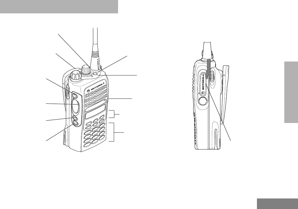
PARTS OF THE RADIO
PRO7550
™
and PRO7650
™
Models
(programmable)
Side Button 1 (A)
(programmable)
Side Button 3 (C)
(programmable)
Top Button (D)
Keypad
Front Buttons
Mode Selector Knob
Button
Push-to-Talk (PTT)
On/Off/Volume Knob
LED Indicator
(programmable)
Side Button 2 (B)
Microphone
(Select Key)
Side
Connector
Cover
Side
Connector
Cover

16
English
RADIO OVERVIEW
On/Off/Volume Knob
Turns the radio on or off, and adjusts the radio’s
volume.
Mode Selector Knob
Selects the required operation mode.
LED Indicator
Indicates status of battery (see page 26); or (see
table below) power-up, scan, or receipt of a radio
selective call:
Push-to-Talk (PTT) Button
Press and hold down this button to talk; release it to
listen.
Microphone
When sending a message, hold the microphone 1 to
2 inches (2.5 to 5 cm) away from your mouth, and
speak clearly into the microphone.
Keypad Keys
With PTT switch pressed (radio transmitting)
Steady red Radio is transmitting (
PTT
button
pressed)
LED unlit Radio is not transmitting
Flashing red Low battery (conventional mode
only; programmable from the
CPS)
Momentary
green Radio has powered-up success-
fully
Amber In Permanent Monitor (Conven-
tional only)
With PTT Released (radio receiving)
Blinking red
light* Mode busy (conventional
mode only)
Blinking green
light Receipt of a telephone call,
Private Conversation call,
or Call Alert page
123
456
789
*0#

17
English
RADIO OVERVIEW
These keys are used for:
• dialing a phone number.
• entering a specific radio ID number when mak-
ing a private or Call Alert radio call
The following table shows the character cycle for
each key, when entering information for
programming the radio’s lists.
Note:
The sequence in the table above is valid
when entering information on a blank dis-
play. However, when editing existing infor-
mation, the above sequence may differ. For
instance, if the last character entered is a
“
R
”, pressing
7
to enter the next char-
acter, would start the character cycle at “S”
and NOT at “P”.
After the button rolls
over from the number, alpha charac-
ters are displayed again but in lower
case letters.
Key Number of Times the Key is Pressed
123456
0
0
1
1
Blank
space
2
ABC2
3
DEF3
4
GH I4
5
JKL5
6
MNO6
7
PQRS7
8
TUV8
9
WXYZ9
*
*
#
#-+./\

18
English
RADIO OVERVIEW
• When editing existing information, pressing
1
would
ALWAYS
start the character
cycle at the “
blank space
” and
NOT at “1”.
Menu Keys
Selecting a Feature
A unique feature of your radio is its use of the
display to give you quick access to many of the
radio’s features without having to have a dedicated
key for each feature.
The names of the features (CALL, MUTE, etc.) are
shown on the display, three at a time. Selection of
features is controlled by the three keys directly
below the feature names: the left key controls the
left feature, the middle key controls the middle
feature, and the right key controls the right feature.
Softkeys (l;l)
When already in Menu Mode, these keys are used
to make Menu selections.
Left and Right Arrow Keys (,/)
The left and right arrow keys are used to scroll the
display forward or backward through the radio’s
features and lists. There is no end point to the list,
so if you continue to scroll in one direction, the
display will “wrap around” back to the beginning of
the list. If you hold either key down, the display will
scroll at a faster rate until the key is released.
The left arrow key is also used for editing when you
are entering information manually from the keypad.
Pressing the left arrow key, when editing numeric
information (such as telephone numbers), will
backspace, and erase the display, one character at
a time. If you have erased all the digits, an additional
press of the left arrow key will return the display to
the pre-programmed list.
Pressing the left arrow key, when editing alphabetic
information (such as member’s names), will move
the cursor one step to the left.
l;l
,./
Softkey 1 Softkey 3
Left Home Right
Softkey 2
19
English
RADIO OVERVIEW
HOME Key (.)
The HOME key will always return you to the home
(default) display. In most cases, this is the current
mode. In addition, if you are using a feature that
requires it, pressing the HOME key will also cause
information to be saved in memory before going to
the home display. Some radio features will
automatically go to the home display when they are
completed, without having to press the HOME key,
thus reducing the number of key presses required.
Menu Display
The menu items can be displayed in normal video or
in reversed video (programmable through the CPS).
All the menu items in the examples in this manual
are shown in reversed video.
The order in which the menu items are displayed is
programmable. Thus, the order of the menu items
on your radio may differ from those shown here in
this manual. In such a situation, press the relevant
softkey to make your menu selections. All
descriptions of functions and displays after the
selection are valid.
LCD Screen and Icons
Displays mode selected, channel, menu, and radio
status information. The top two screen rows show
radio status indicator symbols, explained in the
following table.
Symbol Name and Description
A
XPAND™ Indicator
Indicates that your radio has the com-
panding feature activated.
B
Power Level Indicator
R lights up when your radio is config-
ured to transmit in Low Power. S lights
up when your radio is configured to
transmit in High Power.
A B C F G J
“K P

20
English
RADIO OVERVIEW
Alert Tone Indications
Your radio generates a number of audible tones to
indicate radio operating conditions:
• Low Battery – A low-battery condition is indi-
cated by a high-pitched, cricket-like “chirp-chirp”
when the PTT button is released following a
transmission.
• Successful Power-Up – A short, medium-pitched
tone when the radio is first turned on indicates
that the radio has passed its power-up self test
and is ready for use.
C
Carrier Squelch Indicator
Indicates when the active conventional
mode is being monitored in the carrier
squelch mode;
ON = BEING MONITORED/
OFF = NOT BEING MONITORED.
FCall Received
Flashes when a call or page is received.
G
Scan Indicator
Indicates when the radio is scanning;
ON = SCANNING/OFF =NOT SCAN-
NING.
J
Direct
Indicates whether you are talking
directly to another radio (talkaround), or
through a repeater;
ON = DIRECT
OFF = REPEATER.
Symbol Name and Description
K
Programming/Viewing Mode
Indicates when the radio is in the pro-
gramming or viewing mode;
ON = IN VIEWING MODE
BLINKING = IN PROGRAMMING
MODE.
P
Battery Level Indicator
Shows the remaining charge in your
battery, based on how many bars are
displayed.
Flashing, indicates flat battery.
Symbol Name and Description

21
English
RADIO OVERVIEW
• Unsuccessful Power-Up – A short, low-pitched
tone when the radio is first turned on indicates
that the radio has failed its power-up self test
and is not ready for use. Contact your service
representative for service.
• Transmit on Receive-Only Mode – If you press
the PTT button while tuned to a “receive-only”
mode, you will hear a continuous, low-pitched
alert tone, indicating that no transmission is pos-
sible on this mode. This tone will continue until
the PTT button is released.
• Transmit Inhibit on Busy Mode – If you press the
PTT button while the mode is busy, you will hear
a continuous, low-pitched alert tone, indicating
that no transmission is possible on this mode.
This tone will continue until the PTT button is
released.
• Transmit Inhibit on Flat Battery – If you press the
PTT button while the battery is flat, you will hear
a continuous, low pitched alert tone, indicating
that transmission is impossible.
• Invalid Mode – A continuous, low-pitched tone is
heard when an invalid or unprogrammed opera-
tion is attempted on the radio.
• Valid (Good) Key Press – A short, medium-
pitched tone when a keypad key is pressed indi-
cates that the key press was accepted.
• Invalid (Bad) Key Press – A short, low-pitched
tone when a keypad key is pressed indicates
that the key press was rejected.
• Failsoft (Trunked Systems Only) – A faint “beep-
ing” tone every ten seconds indicates that the
radio is operating in the failsoft mode.
• Time-Out Timer Warning – Your radio’s time-out
timer limits the length of your transmission time.
When you are pressing the PTT button (trans-
mitting), a short, low-pitched warning tone will
sound four seconds before the allotted time will
expire.
• Time-Out Timer Timed-Out – If you hold down
the PTT button longer than the time-out timer’s
allotted time, a continuous, low-pitched tone will
sound, indicating that your transmission has
been cut off. This tone will continue until the PTT
button is released.
• Phone Busy – A “bah-bah-bah-bah” tone when
telephone interconnect is accessed indicates
that all available modes are busy and the radio is
in queue for the next available phone line.
• Call Alert™ (Page) Received – A group of four
medium-pitched tones every five seconds indi-
cates that your radio has received a Call Alert
page.

22
English
RADIO OVERVIEW
• Call Alert™ (Page) Sent – A single medium-
pitched tone (central acknowledge), followed by
a group of four medium-pitched tones indicates
that a Call Alert page sent by your radio has
been received by the target radio.
• Private Conversation™ Call Received – A group
of two medium-pitched tones indicates that your
radio has received a Private Conversation call.
This sequence is repeated every five seconds
for approximately 20 seconds for enhanced Pri-
vate Conversation.
• Trunked System Busy (Trunked Systems Only) –
A “bah-bah-bah-bah” tone when a trunked sys-
tem is accessed indicates that all available chan-
nels are busy and the radio is in queue for the
next available channel.
• Call Back (Trunked Systems Only) – A group of
three medium-pitched tones (di-di-dit) indicates
that a talkgroup is now available for your previ-
ously requested transmission.
Programmable Buttons
Several of your radio’s buttons can be programmed
by your dealer as shortcuts to many of the radio’s
features.
Check with your dealer for a complete list of
functions your radio supports.
Programmable buttons include:
• The three Side Buttons (A, B, C) and the Top
Button (D)
• On keypad radios only, the three Front
Buttons (P1, P2, P3)
Each button can access up to two features,
depending on the type of button press:
•short press—quickly pressing and
releasing the programmable buttons, or
•long press—pressing and holding the
programmable buttons for a period of time (pro-
grammable for 1/2 to 16 seconds), or
•hold down—pressing and holding down the pro-
grammable buttons while checking status or
making adjustments.
The following table summarizes the programmable
features available.
In the “Button” column, have your dealer write down
the programmable buttons next to the features that
have been programmed to them.
Use the abbreviations (e.g., A for Side
Button 1, D for Top Button, etc.) shown in the radio
illustration at the front of this manual.
Also, where a choice exists, have your dealer
indicate whether the button press is short press
(SP) or long press (LP).

23
English
RADIO OVERVIEW
Check with your dealer for a complete list of features
your radio supports.
Button Short Press Long Press Hold Down
Monitor/Perma-
nent Monitor Temporarily monitors the
selected channel for any activity. Continually monitors
the selected channel. Monitors the selected
channel for any activity.
Volume Set — — Sounds a tone for
adjusting the radio’s vol-
ume level.
Scan Toggles between the start/stop
of the Scan operation. ——
Nuisance Delete Temporarily deletes an
unwanted active scan member. ——
Search Makes a system search.
Light Turns on/off your radio’s back-
light. ——
Call Enters or exits a Private call.
Page Enters or exits a Call Alert.
Call Response Respond to or exit from a Private
Call or Call Alert. ——
Phone Enters or leaves Phone mode. — —

24
English
RADIO OVERVIEW
TRUNKED RADIO SYSTEMS
PRO7550 and PRO7650 radios can operate on both
Privacy Plus™ trunked
and
conventional
radio
systems.
Conventional
typically refers to radio-to-radio
communication, sometimes through a repeater.
A
trunked
radio system allows a large number of
users to share a relatively small number of
frequencies without interfering with each other.
The air time of all the repeaters in the trunked
system is pooled, which maximizes the amount of
air time available to any one radio, and minimizes
channel congestion.
Some of the benefits of trunked two-way radio
systems are:
• No channel monitoring required prior to trans-
mission.
• Improved system access.
• Automatic channel selection.
• Increased privacy among members of the same
group.
• Only one attempt is required to access the sys-
tem. If all channels are busy, the call request
enters a queue and the central controller auto-
matically assigns the next available channel. Two
(2) medium-pitched tones followed by one (1)
high-pitched tone sounds when the call can be
made.

25
English
GETTING STARTED
GETTING STARTED
BATTERY INFORMATION
Charging the Battery
If a battery is new, or its charge level is very low, you
will need to charge it before you can use it.
Note: Batteries are shipped uncharged from the
factory. Always charge a new battery 14 to
16 hours before initial use, regardless of
the status indicated by the charger.
To charge the battery
Place the battery, with or without the radio, in the
charger. The charger LED indicates the charging
progress:
LED Color Status
No LED Indication Battery inserted incorrectly.
Single Green
Flash Successful charger power-
up.
Flashing Red* Battery unchargeable or not
making proper contact.
Steady Red Battery in rapid-charge
mode.
Flashing Yellow Battery in charger, not in rapid-
charge mode but waiting to be
charged.
Flashing Green† Battery 90% (or more)
charged.
Steady Green Battery fully charged.
* Remove the battery from the charger. Clean
battery contacts with isopropyl alcohol applied to
a soft cloth. Place the battery back in the charger.
If the LED indicator continues to flash red,
replace the battery.
† A standard battery may require one hour to
charge to 90%.
LED Color Status

26
English
GETTING STARTED
Battery Charge Status
If programmed by your dealer, you can check your
battery’s charge status by holding down the
preprogrammed Battery Gauge button. The charge
status is shown by the color of the radio’s LED
indicator.
Battery chargers will only charge the Motorola-
authorized batteries listed below; other batteries
may not charge.
Battery
Level LED
Indicator
High Green
Sufficient Yellow
Low Flashing red
Very Low None
Part No. Description
HNN9008 High-Capacity/NiMH
HNN9009 Ultra-High-Capacity/NiMH
HNN9010 Ultra-High-Capacity/Factory
Mutual/NiMH
HNN9011 High-Capacity/Factory Mutual/
NiCd
HNN9012 High-Capacity/NiCd
HNN9013 High-Capacity/Lithium-Ion
27
English
GETTING STARTED
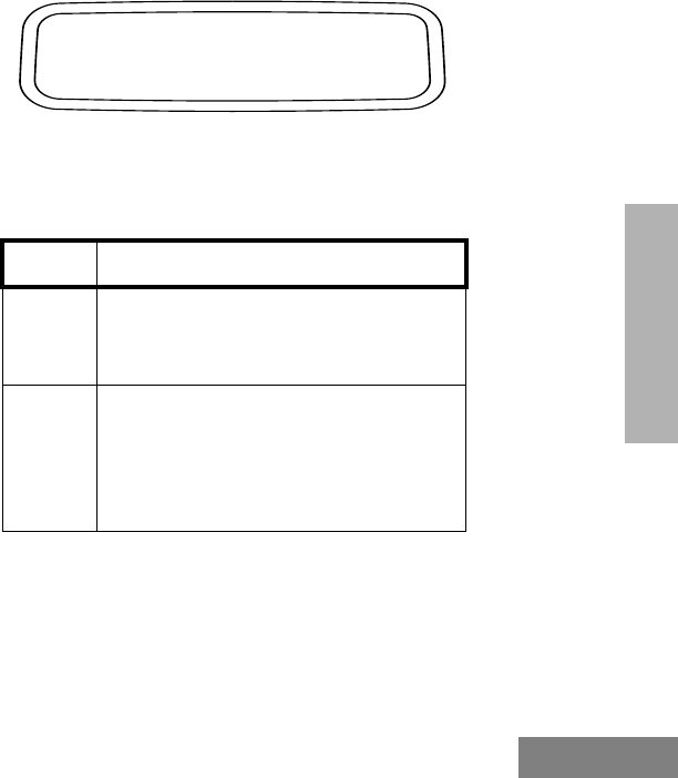
Attaching the Battery Removing the Battery
1Fit the extensions at the bottom of the bat-
tery into the bottom slots on the radio.
2Press the top part of the battery toward the
radio until you hear a click.
1
2
1Turn off the radio (see page 30).
2Slide both battery latches downward.
3Pull the top part of the battery away from
the radio.
3
2
Battery Latches
28
English
GETTING STARTED
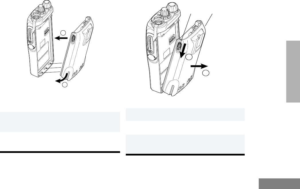
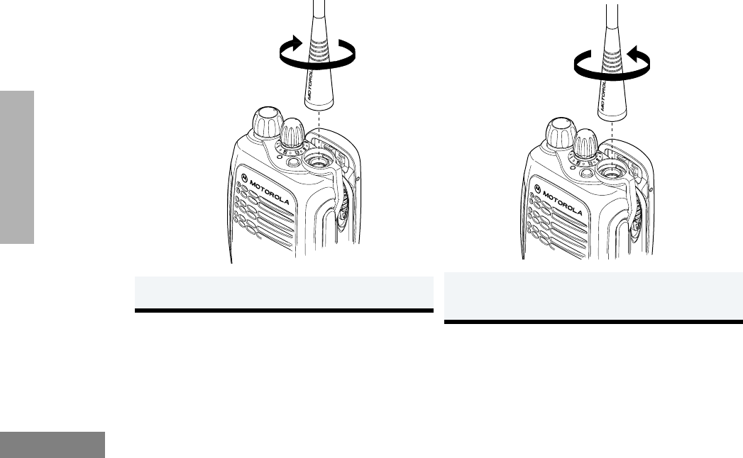
ACCESSORY INFORMATION
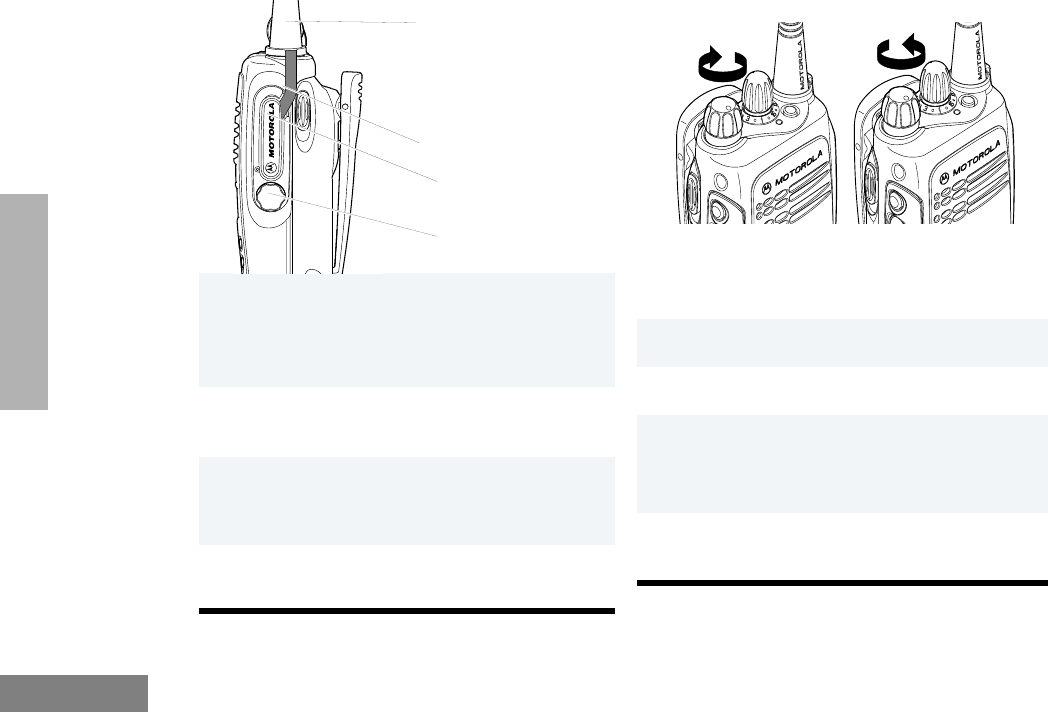
Attaching the Antenna Removing the Antenna
1 Turn the antenna clockwise to attach it. 1Turn the antenna counterclockwise to
remove it.
29
English
GETTING STARTED
Attaching the Belt Clip Removing the Belt Clip
1Align the grooves of the belt clip with those
of the battery.
2Press the belt clip downward until you hear
a click.
1Use a key to press the belt clip tab away
from the battery.
2Slide the belt clip upward to remove it.
2
1
Belt Clip Tab
30
English
GETTING STARTED
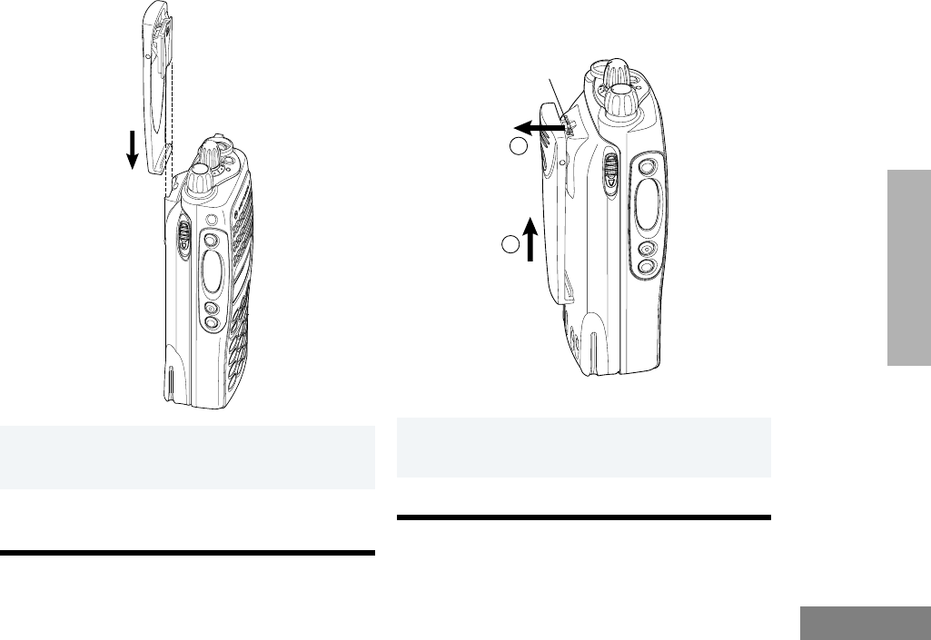
Attaching the Side Connector Cover Turning The Radio On or Off
RECEIVING A TRUNKED CALL
1Place the loop (attached to the side con-
nector cover) over the antenna; then slide it
downward until it touches the top of the
radio.
2Insert the tab on the top of the cover into
the slot above the connector.
3Position the cover over the connector and
align the thumbscrew with the threaded
hole in the radio.
4Tighten the thumbscrew to hold the cover in
place. Do not overtighten the thumbscrew.
Loop
Slot
Thumbscrew
Antenna
1Turn your radio on.
2Adjust your radio’s volume.
3Use the Mode Selector knob to select the
desired trunked talkgroup.
• Make sure the PTT button is released.
4Listen for voice activity. The LED indicator
flashes green when your radio is receiving.
ON OFF

31
English
GETTING STARTED
RADIO SELF TEST
Turn the radio on by rotating the volume control
clockwise. The radio goes through a power-up self
check and, if it passes the check, the display
momentarily shows “SELF TEST.” A good-power-up,
high-pitched tone sounds to indicate that the radio has
passed the self check.
If the radio fails the self check, the display shows
“ERROR XX/XX” (where XX/XX is an alphanumeric
error code), accompanied by a bad-power-up, low-
pitched tone. Turn the radio off, check the battery, and
turn the radio back on. If the radio still does not pass
the self check, a problem exists in the radio. Contact
your nearest Motorola Service Shop.
Note: The power-up self check verifies that the
radio’s microprocessor-based systems are
working, but it does not check all of the rf
components, nor does it check the opera-
tion of all customer-specific features.
Motorola recommends that the functional-
ity of the radio be periodically checked by
an authorized Motorola service shop.

32
English
GETTING STARTED
Notes

33
English
RADIO CALLS (
TRUNKED
RADIO CALLS ( TRUNKED
OPERATION ONLY)
This section outlines the basic functions of your radio.
All references to what is shown on the display is only
valid for PRO7550/PRO7650 radios. Throughout this
section, the display below
is used to indicate the radio’s home display.
SELECTING A ZONE AND MODE
A
mode
is a channel or talkgroup and all the
features that are programmed to it. A
zone
is a
grouping of modes that is selected using the menu
keys. Before you use your radio to receive or send
messages, you should first select the desired zone
and mode.
Selecting a Zone
PLANT POLICE
1/ until
ZONE
is
displayed.
2l (the softkey
below
ZONE
). The
current zone name
blinks on the display.
For example
3 / until the
desired zone name
is displayed.
—or—
Enter the number of
the desired zone.
For example
4 .
5The displayed zone
is the new selected
zone
ZONE MUTE CALL
PLANT POLICE
CITY POLICE
CITY POLICE

34
English
RADIO CALLS (
TRUNKED
Selecting a Mode
RECEIVING A CALL
MAKING A CALL
Conventional Modes
Note: Do not interrupt another user. If the present
mode is programmed to receive PL, ensure
that the mode is not in use by pressing the
monitor button to listen for activity.
• If the mode-busy feature is enabled, a
blinking red LED on receive (PTT switch
released) indicates that the mode is cur-
rently busy.
• If a mode is programmed for receive only,
any attempt to transmit on that mode will
cause an invalid-mode tone to sound until
the PTT switch is released.
1Turn the
Mode Selector knob
to the desired
mode.
2The display shows
the selected mode’s
name.
For example
3If the selected mode
is unprogrammed, an
invalid-mode tone is
heard until a valid
programmed mode is
selected.
1Turn the radio on and select the desired
zone and mode (see
Selecting a Zone and
Mode
).
2Your radio is now set to receive calls on the
selected mode.
PLANT MODE 1
UNPROGRAMMED
1Turn the radio on and select the desired
conventional zone and mode (see
Selecting
a Zone and Mode
).
2Press and hold the PTT switch on the side
of the radio and speak slowly and clearly
into the microphone area. The red LED
lights continuously when the radio is trans-
mitting.
3When you have finished talking, release the
PTT switch to listen.

35
English
RADIO CALLS (
TRUNKED
Trunked Modes
• If you hear a busy signal (a low-frequency “bah-
bah-bah-bah”), release the PTT switch and wait
for a call-back tone (sounds like “di-di-dit”).
When you hear the call-back tone you will have
three seconds to press the PTT switch. This
allows you to make another call without getting a
busy signal.
• If a continuous talk-prohibit tone is heard when
the PTT switch is pressed, transmission is not
possible. The radio may be out of range.
Low-Battery Alert
Your radio emits an alert tone when a low-battery
condition is detected.
Coded Squelch Operation
Tone Private-Line® (PL), Digital Private-Line™ (DPL),
and carrier squelch operation are all available in your
radio, on a per-mode basis.
When in carrier squelch operation, all traffic on the
mode is heard. When in PL or DPL operation, your
radio responds to only those messages intended for
you. When this feature is mode-slaved, PL, DPL, or
carrier squelch is programmed to each mode.
Whenever the radio is operating in carrier squelch, the
display will show C.
Variable RF Power Level (Selected Models
Only)
Radios can have more than one power level. High
power can be programmed on modes where high
power is permitted, and low power can be
programmed on all other modes. The high-/low-power
feature can be selected via the menu keys.
FAILSOFT OPERATION (TRUNKED
SYSTEMS ONLY)
The “failsoft” system ensures continual radio
communications capability during a trunked system
failure. Your radio will automatically go into failsoft
operation, if the central trunking controller fails for
any reason. While in failsoft operation, your radio will
transmit and receive on a predetermined frequency
1Turn the radio on and select the desired
trunked zone and mode (see
Selecting a
Zone and Mode
).
2 Press and hold the PTT switch on the side
of the radio and speak slowly and clearly
into the microphone area. The red LED
lights when the radio is transmitting. When
you have finished talking, release the PTT
switch to listen.

36
English
RADIO CALLS (
TRUNKED
on a conventional mode. When the trunked system
returns to normal operation, the radio will
automatically leave the failsoft operation and return
to trunked operation.
During failsoft operation,
MUTING THE KEYPAD TONES
The radio’s keypad tones, normally heard each time
a keypad key is pressed, can be turned off (muted)
or on (unmuted) at your discretion. To use the
keypad mute feature:
Note: Pressing . or the PTT switch will exit
this menu without changing the mute
selection.
1You will hear a faint
“beeping” sound
every ten seconds.
Alternates between
and
2Your radio becomes unsquelched.
1 / until
MUTE
is
displayed.
FAILSOFT
PLANT POLICE
ZONE MUTE CALL
2Press the softkey
below the desired
mute state (on or
off). The radio
returns to the home
display.
3; (the softkey
below
MUTE
). You will see the cur-
rent mute state
momentarily
or
Then
PLANT POLICE
TONES ON
TONES OFF
ON OFF

37
English
SCAN
SCAN
This section outlines the scan functions of your
radio. All references to what is shown on the display
is only valid for PRO7550/PRO7650 radios.
Throughout this section, the display below
is used to indicate the radio’s home display.
SCAN OPERATION
The scan feature allows you to monitor activity on
different conventional or trunked modes by scanning
a
scan list
of modes. This list can be programmed
with the Customer Programming Software (CPS) or
user programmable.
The table below lists the types of scan operations
available depending on radio model.
Automatic scanning (autoscan) can be programmed
through the CPS. If autoscan is enabled for a mode,
your radio begins scanning, using the mode’s scan
list, whenever you select that mode. The radio will
continue autoscanning until you select a mode that
does not have autoscan enabled.
Turning Scan On or Off with the Keypad)
Conventional Comprises Conventional-Only
Modes.
Talkgroup
Scan
Comprises conventional modes
and trunked modes from more
than one trunking system.
PLANT POLICE
1/ until
SCAN
is
displayed.
2; (the softkey
below
SCAN
). You will see the cur-
rent scan state
momentarily.
or
Then
PHON SCAN CALL
SCAN ON
SCAN OFF
ON OFF

38
English
SCAN
Note: The scan status annunciator, G, is dis-
played when the scan operation is active. It
will be removed from the display when the
scan operation is terminated.
Deleting Nuisance Modes
When the radio scans to a mode you do not wish to
monitor (nuisance mode), you can temporarily delete
that mode from the scan list.
Viewing a Scan List
The
view scan list
feature allows you to view the
members of the scan list associated with the currently
selected mode.
To view a scan list
3Press the softkey
below the desired
scan state (on or off).
The radio returns to
the home display.
1When your radio is locked on the mode to
be deleted, press the nuisance-mode delete
button (programmed via the CPS).
2A valid-keypress chirp is heard, indicating
that the mode has been deleted.
3The radio continues scanning the remaining
modes in the list.
4To resume scanning the deleted mode, you
must leave and reenter scan operation.
PLANT POLICE
1/ until
VIEW
is
displayed.
2 l (the softkey
below
VIEW
).
3; (the softkey
below
SCAN
). The
display shows the
first member of the
scan list.
For example
4Every subsequent press of / will scroll
through subsequent members of the scan
list.
5To leave the scan list feature, press the
HOME key, or the PTT button, or turn the
mode selector knob.
6The radio returns to
the home display.
PAGE STS VIEW
PHON SCAN CALL
FIRE DEP
PLANT POLICE

39
English
SCAN
Note: The programming-mode annunciator, K,
is displayed while list view mode is active.
• The scan status annunciator, G, appears,
indicating that a scan list is being viewed.
Programming a Scan List
The program scan list feature allows you to program
the members of the scan list associated with the
currently selected mode.
To program a scan list
Note: The programming-mode annunciator, K,
blinks while program mode is active.
1/ until
PROG
is
displayed.
2l (the softkey
below
PROG
).
3l (the softkey
below
SCAN
). The
display shows the
current mode
selected.
For example
4Use the mode selector knob to select the
required talkgroup zone.
PROG
SCAN PHON CALL
FIRE DEPT
5, or / to select the required zone. If
the scan status annunciator G is displayed,
the mode is part of the scan list.
6Press the select key to enable or disable the
scan mode.
7After making all the changes, select the
required operating mode.
8Press the HOME key, or the PTT button, or
turn the mode selector knob to commit all
the changes made.

40
English
SCAN
Notes

41
English
TRUNKED FEATURES
TRUNKED FEATURES
This section outlines the trunked features of your
radio. All references to what is shown on the display
is only valid for PRO7550/PRO7650 radios.
Throughout this section, the display below
is used to indicate the radio’s home display.
VIEWING YOUR RADIO’S ID
NUMBER
To view your radio’s ID number:
Note: If your radio has been so programmed, you
can press the call button for quick access
to viewing your radio’s ID number. This
takes you directly to step 3.
ENHANCED PRIVATE CALL
OPERATION
The Enhanced Private Conversation feature not only
allows you to have a conversation that is heard only
by the two parties involved, but also enables you to
determine whether the radio that you are calling is in
service. The radio being called can also view the
calling radio's ID number before answering. You can
then choose whether or not to leave your radio’s ID
number (via a Call Alert page) with the radio you are
calling so that you may be called back. Enhanced
Private Conversation operation is similar to
telephone operation.
1 / until
CALL
is dis-
played.
2l (the softkey below
CALL
).
3The display shows the
last ID number transmit-
ted or received.
4,.
5The display shows your
radio’s ID number.
PLANT POLICE
ZONE MUTE CALL
ID: 722588
my id 741317
6. to return the radio
to the home display.

42
English
TRUNKED FEATURES
Answering a Private Call
Note: If you press the PTT button before you
press the call response button, the
response will be transmitted to everyone in
the talkgroup (a dispatch mode operation).
• After answering a Private Call, the caller’s
ID number is stored in your radio as the
“
last ID number received
”.
• If your radio is configured for Private Call II,
upon receiving a Private Conversation call,
two alert tones sounds, followed by the
received voice.
1Upon receiving a Private
Conversation call, two
alert tones sounds
(repeating every five
seconds for 20 sec-
onds).
Alternates between
and
2The green LED and call received status
annunciator, F, will blink indicating that a call
is being received. You have 20 seconds to
answer the call before the radio automatically
returns to the home display.
3Press the call response button or the call but-
ton.
4The display shows the
incoming caller’s ID
number, and the call
received annunciator
will turn off.
5After viewing the caller’s ID number, you can
decide to either talk privately (go to next step),
or not answer the call by pressing the call
response or call button to return to the home
display.
CALL
PLANT POLICE
ID: 722588
6If you decide to answer the call, press the PTT
button.
7The caller’s ID number
remains displayed for
the duration of the call.
8When finished with conversation, press .
or the call response button to hang up.
9The radio will return to
the home display.
ID: 722588
PLANT POLICE

43
English
TRUNKED FEATURES
Making a Private Call
There are four phases in making a private call,
namely:
• initiating a private call,
• entering the desired radio ID number,
• sending the radio ID number, and
• having the conversation and hanging-up.
Initiating a Private Call
Entering the Desired Radio ID Number
If the last ID number called is the desired
number, go directly to step 5.
To enter a new number
Note: Exactly six digits must be entered for the
radio ID number. If fewer than six digits
were entered, you will hear a bad-keypress
tone and the display will show “INVALID
ENTRY” when attempting to send the radio
ID number. A bad-keypress tone will also
be heard if you try to enter a seventh digit.
• Once you have started entering numbers, the
, key functions as a backspace key. Press-
ing it causes the last digit entered to be erased,
and the cursor moves to the left. When the last
digit is erased, an additional press of this key
causes the last member of the preprogrammed
call list to be displayed; pressing / shows the
first member of the list.
To enter a number from a location in the call list
1/ until
CALL
is dis-
played.
2l (the softkey below
CALL
).
3The display shows the
last ID number transmit-
ted or received.
4a Enter the new six-digit ID number using the
keypad.
ZONE MUTE CALL
ID: 722588
4b On the display, the old ID number disappears
and the new digits appear as they are being
entered.
4c The cursor flashes indicating the location of
the next number to be entered
4a
,
or
/
to enter the call list.
4b Enter the first digit of the location number. If
there are fewer than 10 members in the list,
go directly to step 4e.

44
English
TRUNKED FEATURES
Note: The last member of the list is also the “last
ID transmitted or received” at position “00”
on the list.
• If you enter a location number that does
not exist (for example, “15”), the display will
show “INVALID ENTRY,” and the radio will
sound an invalid-keypress tone and return
back to step 4b of this procedure.
Sending the Radio ID Number
Note: If the radio you are calling is not in service,
you will not hear the ringing and the display
will show “NO ACKNOWLELDGE”. Go to
step 10 to hang up.
• If your radio is configured for Private Call II,
you will not hear the telephone type ring-
ing. Instead you are able to proceed to talk
to the Called party.
4c If there are 10 or more members in the list,
the display shows “ID LOC#X_” (where X is
the first digit). The cursor blinks to show the
location of the second digit.
4d Enter the second digit of the location number.
4e
The radio goes to that
position in the list. The
display alternates
between showing the
member’s name and ID
number.
Alternates
between
and
GILBERTO
ID: 784116
5Press the PTT button to transmit the ID num-
ber.
6If the radio you are calling is on the air, you
will hear a telephone-type ringing for 20 sec-
onds, or until the called radio answers the call.
7If the party you are call-
ing does not answer the
call within twenty sec-
onds, the telephone
ringing stops and an
alert tone sounds.
At this point you can either send a Call Alert™
page, or go to step 10 to hang up.
8If the party you are calling answers the call,
you will hear his/her voice.
NO ANSWER

45
English
TRUNKED FEATURES
Having the Conversation and Hanging-up
Note: Once engaged in a private conversation, if
the radio is left idle for more than one
minute, a momentary warning alert sounds
every six seconds to remind you that dis-
patch calls are not being heard. After two
minutes, a permanent invalid mode tone
sounds.
Leaving a Call Alert™ Page
9Press the PTT button to have a Private Con-
versation with the called person.
10 When finished with your conversation, or if the
radio you called does not answer or is not in
service, press . to hang up.
11 The radio will return to
the home display. PLANT POLICE
1If the party you want to have a Private Call
does not answer the call within twenty sec-
onds, you can choose to leave a Call Alert™
page. This leaves your radio’s ID number with
the called radio so you can be called back
later.
2Press the PTT button to send the Call Alert
page. You will hear five beeps, indicating that
the system has received your ID number and
the radio you are calling is on the air.
3.
4The radio will return to
the home display. PLANT POLICE

46
English
TRUNKED FEATURES
CALL ALERT™ OPERATION
Answering a Call Alert™ Page with a Group
Call
Note: When you received a Call Alert page, you
can enter Private Call mode and call the
paging radio using the latest ID received.
Making a Call Alert™
There are three phases in making a call alert,
namely:
• initiating a call alert,
• entering the radio ID number that you wish to
page, and
• sending the call alert
Initiating a Call Alert
Note: The same list is shared by both Call Alert
and Private Conversation features.
• If your radio has been so programmed, you
can press the page button for quick access
to the Call Alert feature. This will take you
directly to step 3.
1. Upon receiving a Call Alert page, four alert
tones sounds (repeats every 5 seconds).
2. The green LED lights and the Call Received
annunciator, F, blinks indicating a call is
received.
3. Press the PTT button to answer the page.
4. The display shows the
current talkgroup. The
audible alert, LED and
call received annuncia-
tor turns off.
5. The ID number of the radio that paged you is
stored as “the last ID number received.”
6. Have your conversation in the normal manner;
all members of your talkgroup will hear your
response. Press the PTT button to talk;
release the button to listen.
FIRE DEPT
1. / until
PAGE
is dis-
played.
2. l (the softkey below
PAGE
).
3. The display shows the
last ID number transmit-
ted or received.
PAGE PHON VIEW
ID: 722588

47
English
TRUNKED FEATURES
Entering the Radio ID Number that you
Wish to Page
If the last ID number called or
received is the desired number, go
directly to step 5.
To enter a new number
Note: Exactly six digits must be entered for the
radio ID number. If fewer than six digits
were entered, you will hear a bad-keypress
tone when attempting to send the radio ID
number. A bad-keypress tone will also be
heard if you try to enter a seventh digit.
• Once you have started entering numbers,
the , key functions as a backspace key.
Pressing it causes the last digit entered to
be erased, and the cursor moves to the
left. When the last digit is erased, an addi-
tional press of this key causes the last
member of the preprogrammed call list to
be displayed; pressing / shows the first
member of the list.
To enter a number from the call list
To enter a number from a location in the call list
4a. Enter the new six-digit ID number using the
keypad.
4b. On the display, the old ID number disappears
and the new digits appear as they are being
entered.
4c. The cursor flashes indicating the location of
the next number to be entered.
4a. , or /.
4b. / takes you forward to the first or next
member of the list; , takes you back-
wards to the last or previous member of the
list.
4c. When at a member of
the list, the display
alternates between
showing the member’s
name and ID number.
Alternates
between
and
4a. , or / to enter the call list.
4b. Enter the first digit of the location number. If
there are fewer than 10 members in the list,
go directly to step 4e.
GLORIA
ID: 784116

48
English
TRUNKED FEATURES
Note: The last member of the list is also the “last
ID transmitted or received” at position “00”
on the list.
If you enter a location number that does not exist
(for example, “15”), the display will show “INVALID
ENTRY,” and the radio will sound an invalid-key-
press tone and return back to step 4b of this proce-
dure.
Sending the Call Alert
If the page is unsuccessful
If the page is successful
4c. If there are 10 or more members in the list,
the display shows “ID LOC#X_” (where X is
the first digit). The cursor blinks to show the
location of the second digit.
4d. Enter the second digit of the location number.
4e. The radio goes to that
position in the list. The
display alternates
between showing the
member’s name and ID
number.
Alternates
between
and
GLORIA
ID: 784116
5. Press the PTT button to transmit the ID num-
ber.
6a. If you hear one beep, the ID number has
been received by the system, but the radio
you are paging is not on the air; your radio
remains in the Call Alert mode.
If after six seconds the called radio fails to
acknowledge the alert, a low-pitched alert
tone sounds and the display changes to “NO
ACKNOWLEDGE”.
6b. Press the PTT button to send the ID number
again, or press . to hang up and return to
the home display.
6a. If you hear five beeps, the ID number has
been received by the system, and the radio
you are paging is on the air and has received
your page.
6b. The radio automatically
returns to the home dis-
play PLANT POLICE

49
English
TRUNKED FEATURES
PROGRAMMING THE RADIO’S
LISTS
Programming the Telephone List Numbers
This feature lets you use the radio’s keypad to change
the telephone numbers assigned to any of the
telephone list members. Each phone number can have
up to 16 digits.
To change the telephone list
1. / until
PROG
is dis-
played.
2. l (the softkey
below
PROG
).
3. ; (the softkey below
PHON
). The display
shows the first program-
mable member of the
telephone list.
4. / or ,,—or—
Use the keypad to enter the desired member’s
position number (1 to 19) to view the other
members of the telephone list.
PROG
SCAN PHON CALL
FIRE DEPT
5. When you stop on a
member of the list, the
display will alternate
between showing the
member’s name and
telephone number.
Alternates between
and
6. Press the
select
key to enter edit mode.
7. A short press would
enable the editing of the
telephone number. The
display shows the cur-
rent member’s telephone
number.
8. A long press would
enable the editing of the
member’s name. The
display shows the cur-
rent member’s name.
9. Use any of the alphanumeric keys to make the
changes. The blinking cursor indicates the
position of the next number to be added. If
you require a pause in the phone dialing
sequence (to allow for a delay), you can do so
by first pressing the “*” key, followed by press-
ing the “#” key. The display will show a “P” for
pause (see page 16).
POLICE DEPT
5556213
5556213
POLICE DEPT

50
English
TRUNKED FEATURES
Note: The programming-mode annunciator, K,
blinks while program mode is active.
• In the edit mode, the , key functions as
a backspace key. Pressing it will erase the
previous digit, and the cursor will move to
the left. When the last digit on the display
has been erased, additional presses of this
key or the / key will cause you to leave
the edit mode without making any
changes.
• You can only enter a maximum of 16 digits
in any entry for the telephone list. When
this maximum is reached, the cursor will
disappear. If you try to add any more digits,
you will hear an invalid (bad) keypress alert
tone.
Programming the Call List
This feature lets you use the radio’s keypad to
change the radio ID numbers assigned to the call list
used by the trunked Private Conversation™ and
Call Alert™ features.To change the call list radio ID
numbers.
10. When you have finished changing the tele-
phone number, press the
select
key again.
The change is saved in the radio’s memory.
11. You are returned to step
5. The display will again
alternate between
showing the member’s
name and telephone
number. You can now
change additional num-
bers.
Alternates between
and
12. When you have finished making changes,
press
.
to exit program mode.
13. The radio will return to
the home display.
POLICE DEPT
5556445
PLANT POLICE
1. / until
PROG
is dis-
played.
2. l (the softkey below
PROG
).
3. l (the softkey below
CALL
). The display
shows the first program-
mable member of the
call list.
DIR PHON PROG
SCAN PHON CALL
RICARDO

51
English
TRUNKED FEATURES
4. l (the softkey below
CALL
). The display
shows the first program-
mable member of the
call list.
5. / or ,
—or—
Use the keypad to enter the desired member’s
position number (1 to 19) to view the other
members of the call list.
6. When you stop on a
member of the list, the
display will alternate
between showing the
member’s name and
radio ID number.
Alternates between
and
7. Press the
Select
key (see page 15) to enter
edit mode.
8. A short press would
enable the editing of the
radio ID. The display
shows the current mem-
ber’s radio ID number.
GILBERTO
ID: 753951
ID: 753951
9. A long press would
enable the editing of the
member’s name. The
display shows the cur-
rent member’s name.
10. Use any of the alphanumeric keys to make the
changes. The blinking cursor indicates the
position of the next number to be adsee page
16see page 16).
11. When you have finished changing the num-
ber, press the
select
key again. The change is
saved in the radio’s memory.
12. You are returned to step
5. The display will again
alternate between
showing the member’s
name and radio ID num-
ber. You can now
change additional num-
bers.
Alternates between
and
13. When you have finished making changes,
press . to exit program mode.
14. The radio will return to
the home display.
GIBERTO
GILBERTO
ID: 753853
PLANT POLICE

52
English
TRUNKED FEATURES
Note: The programming-mode annunciator, K,
blinks while program mode is active.
• In the edit mode, the , key functions as
a backspace key. Pressing it will erase the
previous numeric digit, and the cursor will
move to the left. When the last digit on the
display has been erased, additional
presses of this key or the / key will
cause you to leave the edit mode without
making any changes (see page 18).
• When the maximum number of digits for
the radio ID is reached, the cursor will dis-
appear. If you try to add any more digits,
you will hear an invalid (bad) keypress alert
tone.
TRUNKED TELEPHONE OPERATION
The trunked telephone feature allows you to receive
calls using your trunked radio. When you are dialing
from the keypad, your radio may be programmed
with either buffered dial (you enter all digits and
press the PTT button before the digits are sent out)
or live dial (each digit is sent out as it is pressed).
Answering a Telephone Call
Note: The call received status annunciator, F,
flashes when you receive a call, but is not
displayed when you answer the call.
1. When a telephone call is
being received, you will
hear telephone-type
ringing.
Alternates between
and
2. Press the pre-pro-
grammed phone button
or call response button
to answer the call.
3. Carry on with your conversation in the normal
manner. Press the PTT button to talk; release
the PTT button to listen.
4. When you have finished your conversation,
press . or the phone button to hang up.
5. The radio will return to
the home display.
PLANT POLICE
PHONE CALL
PHONE CALL
PLANT POLICE

53
English
TRUNKED FEATURES
Making a Telephone Call
There are three phases in making a phone call,
namely:
• accessing the telephone system,
• sending the telephone number,
• having the conversation and hanging-up.
Accessing the Telephone System
Sending the Telephone Number
Sending the telephone number using the
keypad
1. / until
PHON
is dis-
played.
2. l (the softkey below
PHONE
).
3. Your radio attempts to access the telephone
system.
4. If you connect successfully, you will hear a dial
tone.
5. The display will show
the last number dialed.
MSG SCAN PHON
5551135
6a. The number can now be entered from the
keypad, using any of the numeric (0 – 9)
keys, and the “*” and “#” keys. The cursor
flashes to indicate the location of the next
digit to be entered. A pause can be entered in
the telephone number by first pressing the “*”
key, then the “#” key (Buffered dial only - The
pause will be shown on the display as a “P”).
6b. If your radio is programmed for “live dial,” each
digit is sent out as its key is pressed.
—or—
If your radio is programmed for “buffered dial,”
each digit is temporarily stored as you enter
them. After entering the number, press the
PTT button to send out the number.
6c. The telephone number will be sent out; you
will hear tones as they are sent. If you hear a
busy signal, go to step 8 for hang-up proce-
dure.

54
English
TRUNKED FEATURES
Sending the telephone number using a num-
ber on the telephone list Sending the telephone number using a location in the
telephone list
6a. , or /, to enter the telephone list.
/ takes you forward to the next member of
the list; , takes you backwards to the pre-
vious member of the list.
6b. Stop at the member you wish to call.
6c.
The display alternates
between showing the
member’s name and
telephone number.
Alternates between
and
6d. Press the PTT button.
6e. The telephone number
will be sent out; you will
hear tones as they are
sent.
6f. If you hear a busy signal, go to step 8 for
hang-up procedure.
POLICE DEPT
5556445
POLICE DEPT
6a. , or /, to enter the telephone list.
6b. Enter the location (any preprogrammed loca-
tion from 1 through 19) of the number you
wish to call.
6c. The radio will go to the selected location.
6d.
The display alternates
between showing the
member’s name and
telephone number.
Alternates between
and
6e. Press the PTT button.
6f. The telephone number
will be sent out; you will
hear tones as they are
sent.
6g. If you hear a busy signal, go to step 8 for
hang-up procedure.
POLICE DEPT
5556445
POLICE DEPT

55
English
TRUNKED FEATURES
Having the Conversation and Hanging Up
• You can press the pre-programmed phone but-
ton for quick access to the telephone call feature.
This will take you directly to step 3.
• The “PLEASE WAIT” message is a timed mes-
sage. If you cannot access the telephone system
(no dial tone heard), press key or the phone but-
ton to hang up, and start again at step 1 of this
procedure.
• If you are out of range of the trunked system or
the phone interconnect is out of service, “NO
PHONE” is displayed and a continuous low-
pitched tone sounds.
• If the trunked phone interconnect is in use, a
busy tone sounds and “PHONE BUSY” is dis-
played.
• When the maximum number of digits have been
entered (buffered dial only), the cursor will disap-
pear.
• In the edit mode, the, key functions as a back-
space key. Pressing this key erases the last digit
entered, and moves the cursor to the left. When
the last digit on the display is erased, additional
presses of this key causes the last member of
the preprogrammed telephone list to be dis-
played; pressing the / key displays the first mem-
ber of the list.
• After reaching the number you are calling, you
may need to dial an extension number before
you can reach your party. Here, enter the exten-
sion number from the keypad or (if so pro-
grammed) use the arrow keys to find the
extension number in the telephone list. If you
have live dial, the number is sent as the keys are
pressed. If you have buffered dial, press the PTT
button again to send out the extension number.
• Motorola trunked radios generate a high-pitched
go-ahead tone when the systems PTT button is
released. This is heard by the land-line party and
is an indicator to begin talking.
7. If call is answered, communicate in the normal
manner. Press the PTT button to talk; release
the PTT button to listen.
8. When finished with your conversation, or if the
number you called is busy or does not answer,
press . or the phone button to send the
hang-up code.
9. The radio will return to
the home display. PLANT POLICE

56
English
TRUNKED FEATURES
AUTOMATIC MULTIPLE SITE
SELECTION (AMSS) (PRO7650
ONLY)
Note: This feature is only available in the
PRO7650 model. Availability of this
feature is limited to customers operat-
ing in a wide-area trunking system
only.
Forcing a Site Change
Locking and Unlocking a Site
1. Press and hold down the search button to
force the change to a new site.
2. You will hear a tone
while the radio scans for
a new site.
3. The radio automatically
returns to the home dis-
play.
SCANNING
PLANT POLICE
1. / until
SITE
is dis-
played.
2. l (the softkey below
SITE
).
3. The current lock state is
momentarily displayed.
or
4. The display changes to
5. Press the key below the desired lock state.
6. The radio automatically
returns to the home dis-
play.
SITE PAGE CALL
SITE LOCKED
SITE LOCKED
LOCK UNLK
PLANT POLICE

57
English
CONVENTIONAL
CALL
CONVENTIONAL CALL
This section outlines the conventional features of your
radio. .
SELECTING A CONVENTIONAL
CHANNEL
Use the Mode Selector knob to select the
appropriate conventional channel.
SENDING A CONVENTIONAL CALL
Note: In the United States, FCC regulations
require you to monitor the conventional
channels before sending a call. The moni-
tor feature (see page 8) can be accessed
through one of your programmable but-
tons.
To send a conventional call
REPEATER OR TALKAROUND
MODE
This feature allows you to bypass the repeater and talk
directly to another portable radio. This is known as the
talkaround mode. The transmit frequency is the same
as the receive frequency.
• In REPEATER mode, you talk through the
repeater, which increases the radio's operating
range. The transmit frequency is not the same
as the receive frequency.
• If the REPEATER or TALKAROUND feature is
programmed to a mode, that mode operates on
either direct or repeat operation.
1Hold the radio in a vertical posi-
tion at a distance of about 1 to 2
inches (2.5 to 5 cm) from your
mouth.
2Press the PTT button and speak clearly into
the microphone. The LED indicator lights
steady red while the call is being sent.
3Release the PTT button to listen.
58
English
CONVENTIONAL
CALL
• If the repeat/direct feature is programmed to the
keypad, you can change the repeat/direct setting
by doing the following.
SMART PTT
Smart PTT is a per-mode feature which gives the
system manager better control of radio operators.
When smart PTT is enabled in your radio, you cannot
transmit on an active mode. Three radio-wide
variations of smart PTT are available.
•Transmit Inhibit on Busy Mode—you are pre-
vented from transmitting if any activity is
detected on the mode.
•Transmit Inhibit on Busy Mode with Wrong
Squelch Code—you are prevented from trans-
mitting on an active mode with a squelch code
other than your own. If the PL code is the same
as yours, you are allowed to transmit.
•Quick-Key Override—This feature can work in
conjunction with either of the two above varia-
tions. This feature allows you to override the
transmit-inhibit state by quick-keying (two PTT
button presses within a programmable period --
the default is one second -- of each other) the
radio.
Note: If you try to transmit (press the PTT button)
on a smart PTT mode that is busy, a con-
tinuous alert tone is generated until the
PTT button is released; the transmission is
inhibited.
• The red LED blinks when the radio is
receiving indicating that the mode is busy.
1/ until
DIR
is dis-
played.
2l (the softkey below
DIR
).
3The current talkaround
state appears on the
display for a few sec-
onds. or
4Then, the display
prompts for the new
state.
5l below the desired talkaround state:
repeat (
RPTR
) or direct (
DIR
).
6The radio returns to the
home display.
DIR PWR PROG
REPEATER MODE
DIRECT MODE
DIR RPTR
PLANT POLICE

59
English
WARRANTY
WARRANTY
LIMITED WARRANTY
MOTOROLA COMMUNICATION
PRODUCTS
I. WHAT THIS WARRANTY COVERS AND
FOR HOW LONG:
MOTOROLA INC. (“MOTOROLA”) war-
rants the MOTOROLA manufactured Com-
munication Products listed below
(“Product”) against defects in material and
workmanship under normal use and ser-
vice for a period of time from the date of
purchase as scheduled below:
Motorola, at its option, will at no charge
either repair the Product (with new or
reconditioned parts), replace it (with a new
or reconditioned Product), or refund the
purchase price of the Product during the
warranty period provided it is returned in
accordance with the terms of this warranty.
Replaced parts or boards are warranted
for the balance of the original applicable
warranty period. All replaced parts of Prod-
uct shall become the property of MOTOR-
OLA.
This express limited warranty is extended
by MOTOROLA to the original end user
purchaser only and is not assignable or
transferable to any other party. This is the
complete warranty for the Product
manufactured by MOTOROLA.
MOTOROLA assumes no obligations or
liability for additions or modifications to this
warranty unless made in writing and
signed by an officer of MOTOROLA.
Unless made in a separate agreement
between MOTOROLA and the original end
user purchaser, MOTOROLA does not
warrant the installation, maintenance or
service of the Product.
MOTOROLA cannot be responsible in any
way for any ancillary equipment not
PRO7550/PRO7650
Portable Units Two (2) Years
Product Accessories One (1) Year

60
English
WARRANTY
furnished by MOTOROLA which is
attached to or used in connection with the
Product, or for operation of the Product
with any ancillary equipment, and all such
equipment is expressly excluded from this
warranty. Because each system which may
use the Product is unique, MOTOROLA
disclaims liability for range, coverage, or
operation of the system as a whole under
this warranty.
II. GENERAL PROVISIONS:
This warranty sets forth the full extent of
MOTOROLA'S responsibilities regarding
the Product. Repair, replacement or refund
of the purchase price, at MOTOROLA’s
option, is the exclusive remedy. THIS
WARRANTY IS GIVEN IN LIEU OF ALL
OTHER EXPRESS WARRANTIES.
IMPLIED WARRANTIES, INCLUDING
WITHOUT LIMITATION, IMPLIED
WARRANTIES OF MERCHANTABILITY
AND FITNESS FOR A PARTICULAR
PURPOSE, ARE LIMITED TO THE
DURATION OF THIS LIMITED
WARRANTY. IN NO EVENT SHALL
MOTOROLA BE LIABLE FOR DAMAGES
IN EXCESS OF THE PURCHASE PRICE
OF THE PRODUCT, FOR ANY LOSS OF
USE, LOSS OF TIME, INCONVENIENCE,
COMMERCIAL LOSS, LOST PROFITS
OR SAVINGS OR OTHER INCIDENTAL,
SPECIAL OR CONSEQUENTIAL
DAMAGES ARISING OUT OF THE USE
OR INABILITY TO USE SUCH PRODUCT,
TO THE FULL EXTENT SUCH MAY BE
DISCLAIMED BY LAW.
III. STATE LAW RIGHTS:
SOME STATES DO NOT ALLOW THE
EXCLUSION OR LIMITATION OF
INCIDENTAL OR CONSEQUENTIAL
DAMAGES OR LIMITATION ON HOW
LONG AN IMPLIED WARRANTY LASTS,
SO THE ABOVE LIMITATION OR
EXCLUSIONS MAY NOT APPLY.
This warranty gives specific legal rights,
and there may be other rights which may
vary from state to state.

61
English
WARRANTY
IV. HOW TO GET WARRANTY SERVICE:
You must provide proof of purchase
(bearing the date of purchase and Product
item serial number) in order to receive
warranty service and, also, deliver or send
the Product item, transportation and
insurance prepaid, to an authorized
warranty service location. Warranty service
will be provided by Motorola through one of
its authorized warranty service locations. If
you first contact the company which sold
you the Product (e.g., dealer or
communication service provider), it can
facilitate your obtaining warranty service.
You can also call Motorola at 1-800-927-
2744 US/Canada.
V. WHAT THIS WARRANTY DOES NOT
COVER:
A) Defects or damage resulting from use of the
Product in other than its normal and
customary manner.
B) Defects or damage from misuse, accident,
water, or neglect.
C) Defects or damage from improper testing,
operation, maintenance, installation,
alteration, modification, or adjustment.
D) Breakage or damage to antennas unless
caused directly by defects in material
workmanship.
E) A Product subjected to unauthorized
Product modifications, disassemblies or
repairs (including, without limitation, the
addition to the Product of non-Motorola
supplied equipment) which adversely affect
performance of the Product or interfere with
Motorola's normal warranty inspection and
testing of the Product to verify any warranty
claim.
F) Product which has had the serial number
removed or made illegible.
G) Rechargeable batteries if:
1) any of the seals on the battery
enclosure of cells are broken or show
evidence of tampering.
2) the damage or defect is caused by
charging or using the battery in
equipment or service other than the
Product for which it is specified.
H) Freight costs to the repair depot.
I) A Product which, due to illegal or
unauthorized alteration of the software/
firmware in the Product, does not function in
accordance with MOTOROLA’s published

62
English
WARRANTY
specifications or the FCC type acceptance
labeling in effect for the Product at the time
the Product was initially distributed from
MOTOROLA.
J) Scratches or other cosmetic damage to
Product surfaces that does not affect the
operation of the Product.
K) Normal and customary wear and tear.
VI. PATENT AND SOFTWARE PROVISIONS:
MOTOROLA will defend, at its own expense, any
suit brought against the end user purchaser to
the extent that it is based on a claim that the
Product or parts infringe a United States patent,
and MOTOROLA will pay those costs and
damages finally awarded against the end user
purchaser in any such suit which are attributable
to any such claim, but such defense and
payments are conditioned on the following:
A) that MOTOROLA will be notified promptly in
writing by such purchaser of any notice of
such claim;
B) that MOTOROLA will have sole control of the
defense of such suit and all negotiations for
its settlement or compromise; and
C) should the Product or parts become, or in
MOTOROLA’s opinion be likely to become,
the subject of a claim of infringement of a
United States patent, that such purchaser
will permit MOTOROLA, at its option and
expense, either to procure for such
purchaser the right to continue using the
Product or parts or to replace or modify the
same so that it becomes non-infringing or to
grant such purchaser a credit for the Product
or parts as depreciated and accept its
return. The depreciation will be an equal
amount per year over the lifetime of the
Product or parts as established by
MOTOROLA.
MOTOROLA will have no liability with respect to
any claim of patent infringement which is based
upon the combination of the Product or parts
furnished hereunder with software, apparatus or
devices not furnished by MOTOROLA, nor will
MOTOROLA have any liability for the use of
ancillary equipment or software not furnished by
MOTOROLA which is attached to or used in
connection with the Product. The foregoing
states the entire liability of MOTOROLA with
respect to infringement of patents by the Product
or any parts thereof.
Laws in the United States and other countries
preserve for MOTOROLA certain exclusive rights
for copyrighted MOTOROLA software such as
the exclusive rights to reproduce in copies and

63
English
WARRANTY
distribute copies of such Motorola software.
MOTOROLA software may be used in only the
Product in which the software was originally
embodied and such software in such Product
may not be replaced, copied, distributed,
modified in any way, or used to produce any
derivative thereof. No other use including, without
limitation, alteration, modification, reproduction,
distribution, or reverse engineering of such
MOTOROLA software or exercise of rights in
such MOTOROLA software is permitted. No
license is granted by implication, estoppel or
otherwise under MOTOROLA patent rights or
copyrights.
VII. GOVERNING LAW:
This Warranty is governed by the laws of the
State of Illinois, USA.

64
English
WARRANTY
Notes
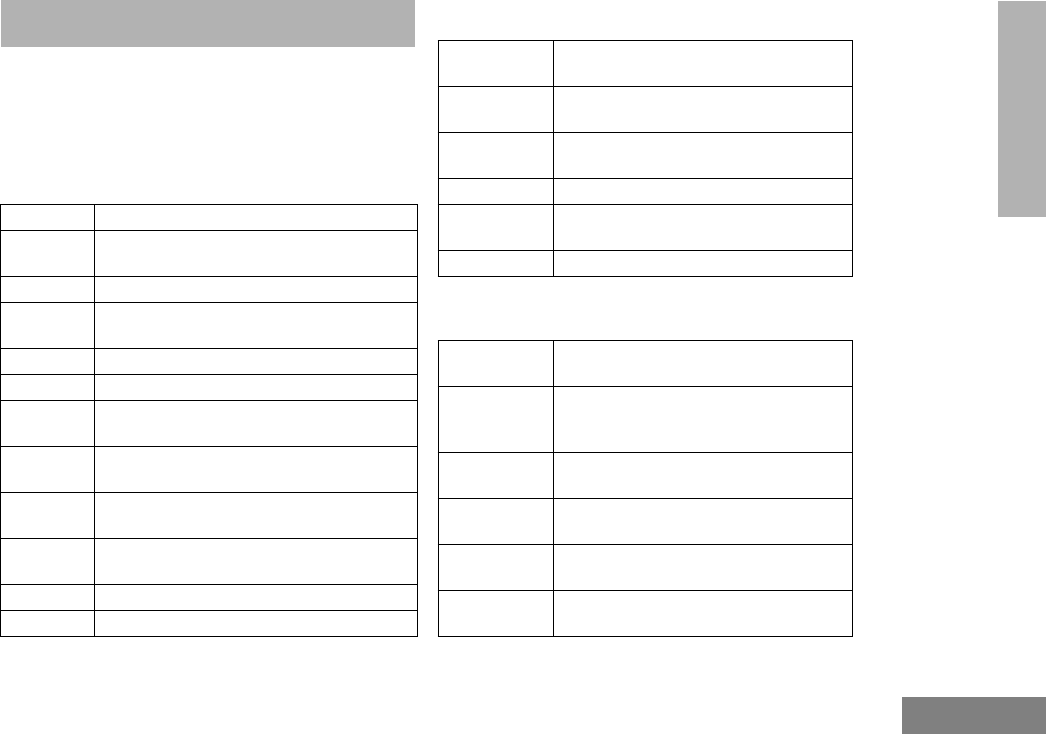
65
English
ACCESSORIES
ACCESSORIES
Motorola offers a number of accessories to enhance
the productivity of your two-way radio. Many of the
available accessories are listed below. For a
complete list, see your Motorola dealer.
CARRY CASES
CHARGERS
HEADSETS
HLN9714_ Spring 2 1/2” Belt Clip
HLN9952_ Belt Clip Carry Holder (compatible with all
batteries and radios)
HLN9652_ Leather Case, Thin Battery with Belt Loop
HLN9665_ Leather Case, Standard Battery with Belt
Loop
HLN9670_ Leather Case, Thin Battery with Swivel
HLN9676_ Leather Case, Standard Battery with Swivel
HLN9677_ Leather DTMF Case, Thin Battery with Belt
Loop
HLN9689_ Leather DTMF Case, Standard Battery with
Belt loop
HLN9690_ Leather DTMF Case, Thin Battery with
Swivel
HLN9694_ Leather DTMF Case, Standard Battery with
Swivel
HLN9701_ Nylon Case, Thin Battery with Belt Loop
HLN9844 Spring 1 1/5” Belt Clip
AAHTN3000_ 110V Single-Unit Rapid Charger, US
Plug
AAHTN3001_ 230V Single-Unit Rapid Charger, Euro
Plug
AAHTN3002_ 230V Single-Unit Rapid Charger, UK
Plug
AAHTN3003_ 110V Multi-Unit Rapid Charger, US Plug
AAHTN3004_ 230V Multi-Unit Rapid Charger, Euro
Plug
AAHTN3005_ 230V Multi-Unit Rapid Charger, UK Plug
AARMN4018 Lightweight Headset with Boom Micro-
phone and In-Line PTT
AARMN4019 Medium Weight Over-the-Head Dual
Muff Headset w/Noise Cancelling Mic &
In-Line PTT
AARMN4020 Heavy Duty Dual Muff Headset with
Noise Cancelling Microphone & PTT
RMN4051 2-Way Hard Hat Mount Headset, Black -
Noise Reduction
RMN4052 Tactical Headband-Style Headset, Gray
- Noise Reduction
RMN4053 Tactical Hard Hat Mount Headset, Gray -
Noise Reduction

66
English
ACCESSORIES
REMOTE SPEAKER MICROPHONES
ADAPTERS
BATTERIES
MISCELLANEOUS
RMN4054 Receive Only Hard Hat Mount Headset,
Gray - Noise Reduction
RMN4055 Receive Only Headband Style Headset
with 3.5mm right angle plug
RKN4097 In-Line PTT Adapter Cable (for use with
RMN4051, RMN4052, RMN4053 Head-
sets)
BDN6648 Heavy Duty Muff Headset with Noise
Cancelling Mic and PTT (must be used
with AAHLN9716 Adapter)
AAHMN9052_ Standard Remote Speaker Microphone
AAHMN9053_ Noise-Cancelling Remote Speaker
Microphone
HLN9716_ Adapter for Audio Accessories
HLN9717_ Adapter for the 3.5mm Audio Accessories
HNN9008_R Small NiMH, High-Capacity
HNN9009_R Large NiMH, Ultra-High-Capacity
HNN9010_R Large NiMH, Ultra-High-Capacity FM
HNN9011_R Large NiCd, High-Capacity FM
HNN9012_R Large NiCd, High-Capacity
HNN9013_R Slim Li-lon, High-Capacity
HLN9820 Dust Cover for Accessory Connector

67
English
ACCESSORIES
ANTENNAS
VHF 136 - 174 MHz, Ferrule Connector
PMAD4012_ VHF 136–155 MHz 9 cm, Stubby
PMAD4013_ VHF 155–174 MHz 9 cm, Stubby
PMAD4014_ VHF 136–155 MHz 14 cm, Standard
Length REd Code
PMAD4015_ VHF 155–174 MHz 14 cm, Standard
Length Black Code
HAD9743_ VHF 162–174MHz, Stubby
PMAD4023_ VHF 150–161 MHz
PMAD4025_ VHF 150–161 MHz, Stubby
PMAE4002_ UHF 403–433 MHz
PMAE4003_ UHF 433–470 MHz
NAE6483_R UHF 403–520 MHz, Whip
PMAE4006_ UHF 470–510 MHz
PMAE4007_ UHF 490–527 MHz
PMAE4008_ UHF 470–530 MHz, Whip
NAF5037_ 800 MHz, Whip
NAF5042_R 800 MHz, Stubby

68
English
ACCESSORIES
Notes
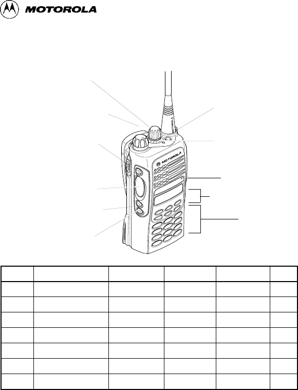
Answering a Telephone Call
Press the preprogrammed phone button or call response button to
answer the call.
Answering a Call Alert™ Page with a Group Call
Press the PTT button to answer the page.
Answering a Private Call
Press the call response button or the call button.
Selecting a Conventional Mode
1.Turn the radio on and select the desired conventional zone and mode
(see
Selecting a Zone and Mode
).
2.Press and hold the PTT switch on the side of the radio and speak
slowly and clearly into the microphone area. The red LED lights
continuously when the radio is transmitting.
PRO7550™ and PRO7650™ Quick Reference Card
Record the functions for your radio’s programmable buttons in the table provided below.
For further information, see page 22 in this User Guide.
(programmable)
Side Button 2 (B)
(programmable)
Top Button (D)
Mode Selector
Knob
Keypad
Front Buttons
Microphone
LED Indicator
On/Off/Volume Knob
(programmable)
Side Button 3 (C)
Push-to-Talk (PTT)
Button
Side Button (A)
(prograrmmable)
(Select Key)
Button Function Short Press Long Press Hold Down Page