Motorola Solutions 89FT5798 Hand Held Portable Transmitter User Manual PRO7550 PRO7650
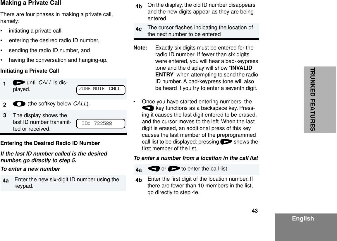
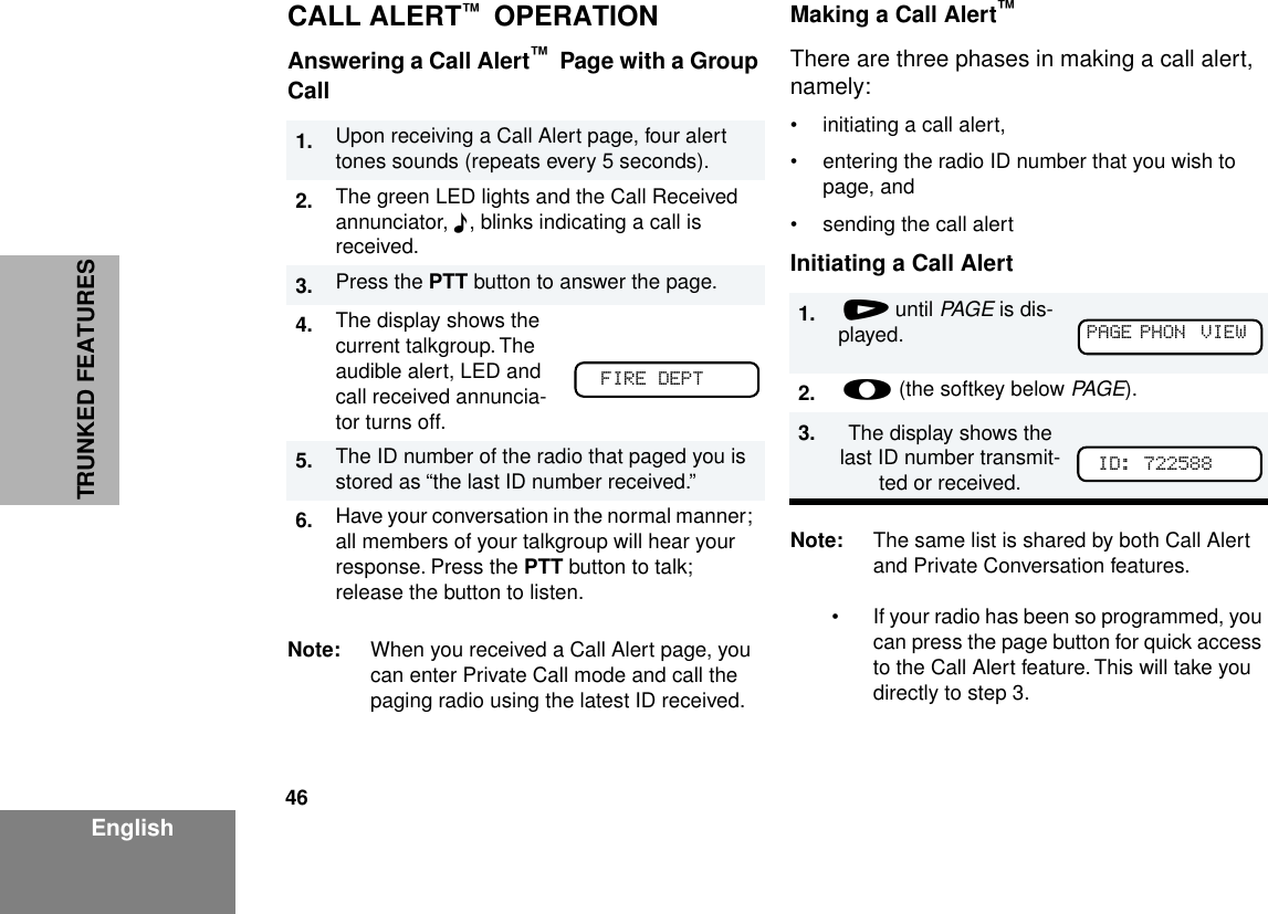
Motorola Solutions, Inc. Hand Held Portable Transmitter PRO7550 PRO7650
UserManual.wiki
>
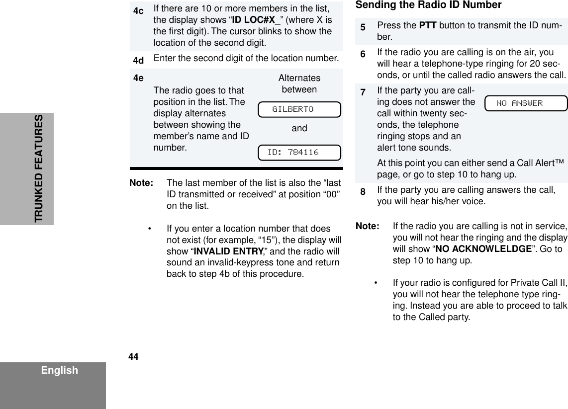
Motorola Solutions
>
89FT5798 User Manual
>
Users Manual
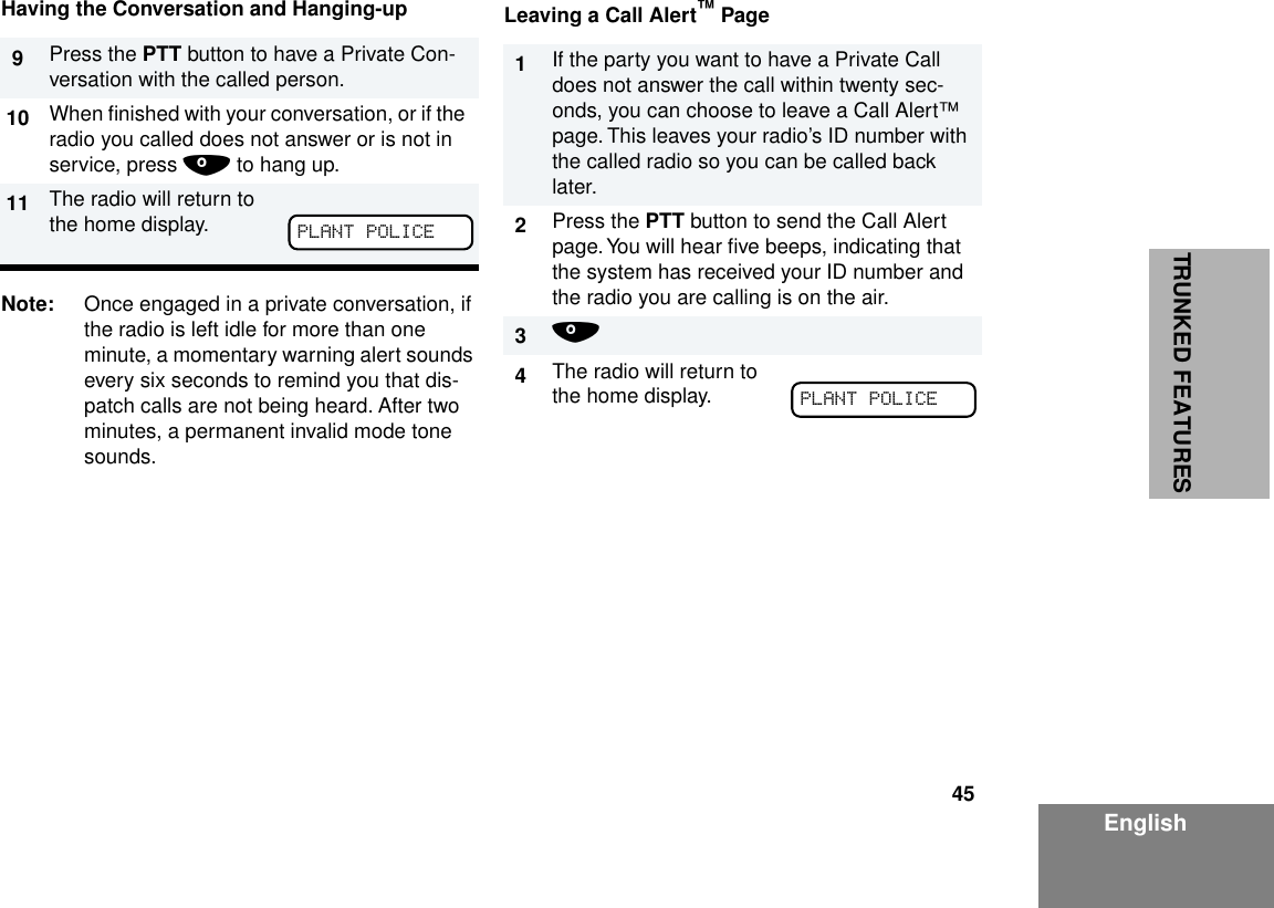
Contents
1.
Users Manual
2.
Amended Users Manual
Users Manual
Navigation menu
Upload a User Manual
Namespaces
Wiki Guide
HTML
PDF
Info
Views
User Manual
Discussion / Help
Navigation
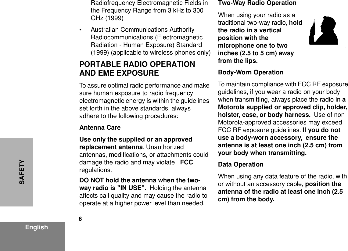
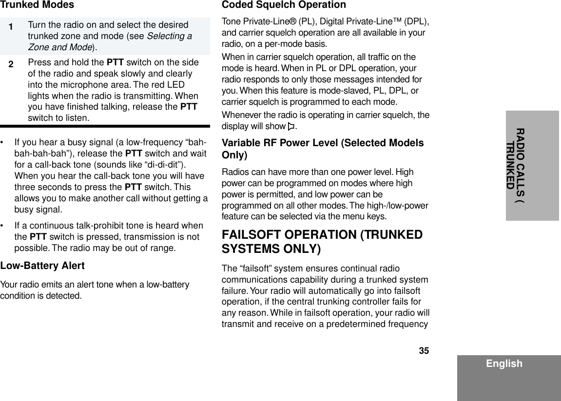
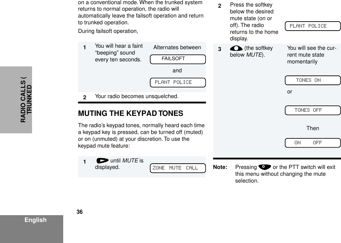
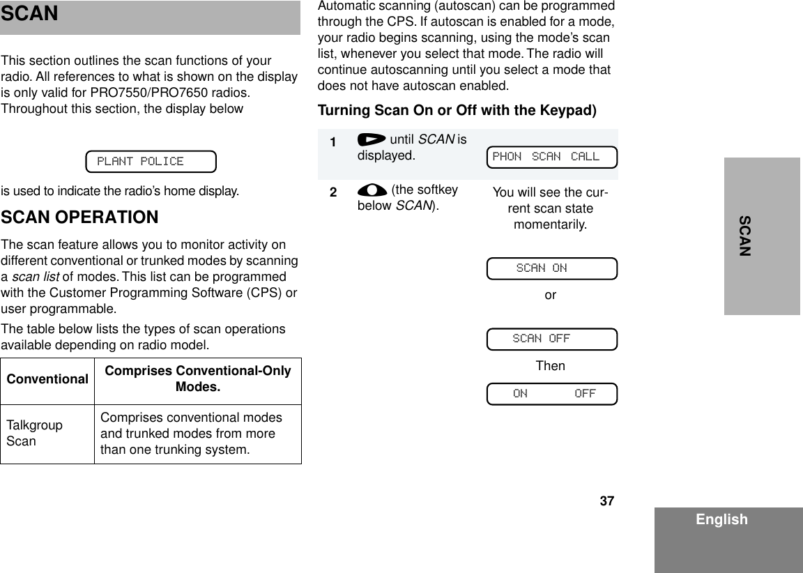
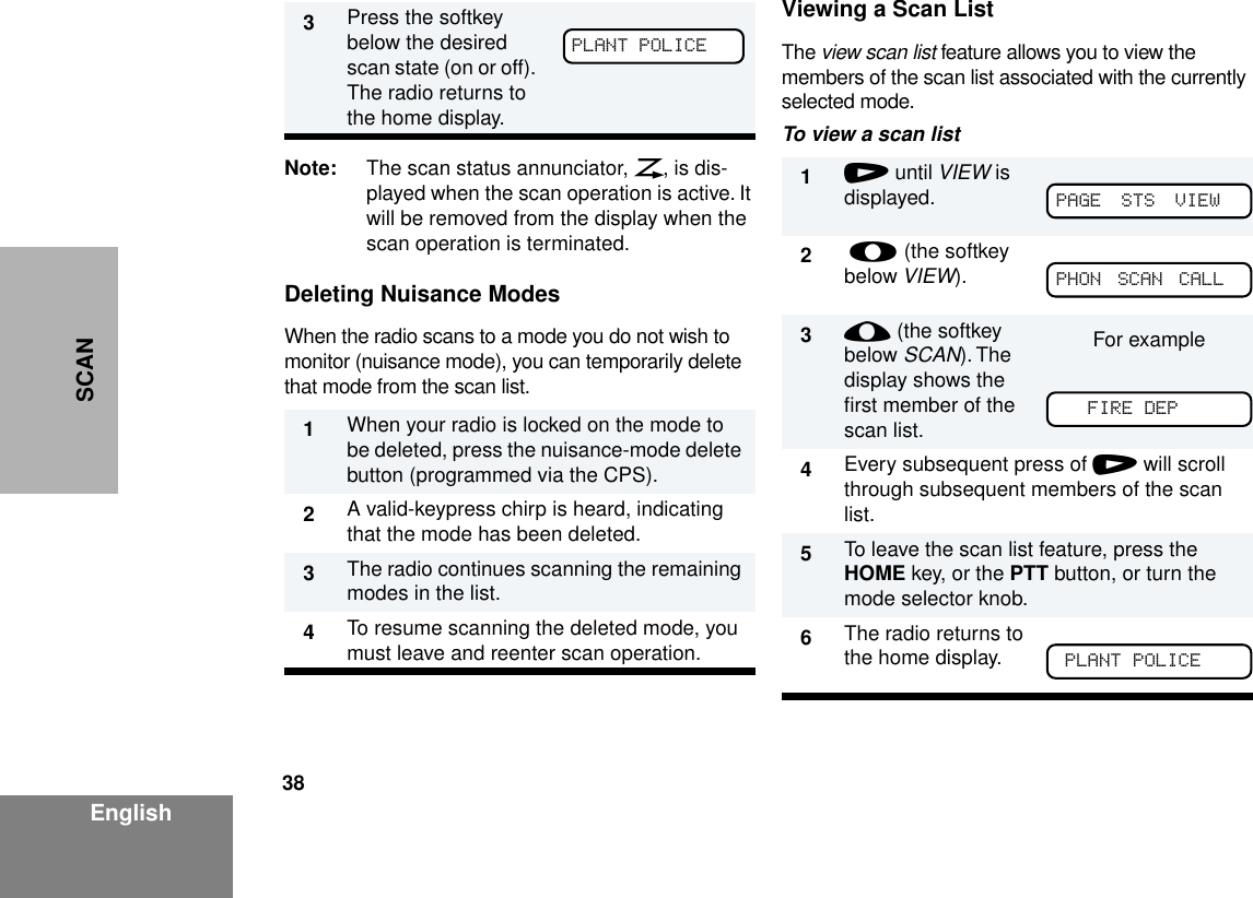
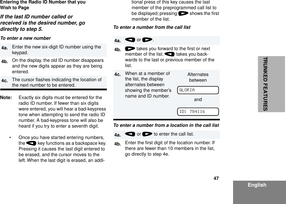
![10 EnglishSAFETY INTRINSICALLY SAFE RADIO INFORMATION FMRC Approved Equipment Anyone intending to use a radio in a location where hazardous concentrations of flammable material exist (hazardous atmosphere) is advised to become familiar with the subject of intrinsic safety and with the National Electric Code NFPA 70 (National Fire Protection Association) Article 500 (hazardous [classified] locations).An Approval Guide, issued by Factory Mutual Research Corporation (FMRC), lists manufacturers and the products approved by FMRC for use in such locations. FMRC has also issued a voluntary approval standard for repair service (“Class Number 3605”).FMRC Approval labels are attached to the radio to identify the unit as being FM Approved for specified hazardous atmospheres. This label specifies the hazardous Class/Division/Group along with the part number of the battery that must be used. Depending on the design of the portable unit, this FM label can be found on the back or the bottom of the radio housing. The FM Approval mark is shown below: WARNINGS • Do not operate radio communications equipment in a hazardous atmosphere unless it is a type especially qualified for such use (e.g., FMRC Approved). An explosion or fire may result.• Do not operate an FMRC Approved Product in a hazardous atmosphere if it has been physically damaged (e.g., cracked housing). An explosion or fire may result.• Do not replace or charge batteries in a hazardous atmosphere. Contact sparking may occur while installing or removing batteries and cause an explosion or fire. WARNINGS • Do not replace or change accessories in a hazardous atmosphere. Contact sparking FMAPPROVED!W A R N I N G!!W A R N I N G!](https://usermanual.wiki/Motorola-Solutions/89FT5798.Users-Manual/User-Guide-119479-Page-10.png)