Motorola Solutions 89FT5871 Portable 2-way radio User Manual 1
Motorola Solutions, Inc. Portable 2-way radio 1
Contents
User Manual 1

DLR1020, DLR1060 models
User Guide
Two-Way Radios
Open Source Software Legal Notices:
This Motorola product contains Open Source Software. For more information
regarding licenses, acknowledgements, required copyright notices and other usage
terms, refer to the documentation for this Motorola product at:
www.motorolasolutions.com/DLR

English
1
CONTENTS
CONTENTS
Contents. . . . . . . . . . . . . . . . . . . . . . . . . . . . .1
Product Safety. . . . . . . . . . . . . . . . . . . . . . . .3
Acoustic Safety . . . . . . . . . . . . . . . . . . . . . . . .3
Introduction . . . . . . . . . . . . . . . . . . . . . . . . . .4
Package Contents. . . . . . . . . . . . . . . . . . . . . .4
FCC Licensing Information . . . . . . . . . . . . .6
Batteries and Chargers Safety
Information. . . . . . . . . . . . . . . . . . . . . . . . . . .7
Operational Safety Guidelines. . . . . . . . . . . . .8
Radio Overview . . . . . . . . . . . . . . . . . . . . . . .9
Parts Of The Radio . . . . . . . . . . . . . . . . . . . . .9
Power Button . . . . . . . . . . . . . . . . . . . . .10
Top Button . . . . . . . . . . . . . . . . . . . . . . .10
Volume Control (+/-) Button . . . . . . . . . .10
Audio Accessory Connector . . . . . . . . . .10
Microphone . . . . . . . . . . . . . . . . . . . . . . .10
Antenna. . . . . . . . . . . . . . . . . . . . . . . . . .10
Tx/Rx Indicator LED . . . . . . . . . . . . . . . .10
Push-to-Talk (PTT) Button . . . . . . . . . . .10
Channel / Menu Button . . . . . . . . . . . . . .10
The Lithium-Ion (Li-Ion) Battery . . . . . . .11
DLR Series Radio Specifications . . . . . .11
Battery Features. . . . . . . . . . . . . . . . . . . . . . 12
About the Li-Ion Battery . . . . . . . . . . . . . 12
Battery Recycling and Disposal . . . . . . . 13
Installing the Lithium-Ion (Li-Ion)
Battery . . . . . . . . . . . . . . . . . . . . . . . . 14
Removing the Lithium-Ion (Li-Ion)
Battery . . . . . . . . . . . . . . . . . . . . . . . . 15
Holster . . . . . . . . . . . . . . . . . . . . . . . . . . 16
Power Supply, Adaptor and DLR Single
Unit Charger (SUC) Tray . . . . . . . . . . 16
Battery Life Information . . . . . . . . . . . . . 17
Battery Status Information . . . . . . . . . . . 17
Estimated Charging Time . . . . . . . . . . . 19
DLR Series Charger LED Indicators . . . 21
DLR Radios and Charger Compatibility. 23
Getting Started . . . . . . . . . . . . . . . . . . . . . . 25
Turning radio ON/OFF . . . . . . . . . . . . . . . . . 26
Adjusting Volume . . . . . . . . . . . . . . . . . . . . . 26
Checking Battery Status. . . . . . . . . . . . . . . . 27
Transmitting and Receiving . . . . . . . . . . . . . 27
Talk Permit Tone (TPT) . . . . . . . . . . . . . 27
Talking to a Group in a Channel . . . . . . 28
Browsing / Selecting a Channel . . . . . . . . . . 28
Private Reply . . . . . . . . . . . . . . . . . . . . . . . . 28
Top Button Options . . . . . . . . . . . . . . . . . . . 28

English
2
CONTENTS
Talk Range . . . . . . . . . . . . . . . . . . . . . . . . . .29
DLR and DTR Radios Compatibility . . . . . . .29
Radio Status . . . . . . . . . . . . . . . . . . . . . . . . .31
Advanced Configuration Mode . . . . . . . . .33
Entering Advanced Configuration Mode . . . .34
Browsing Advanced Configuration Options. .35
PROFILE ID Number . . . . . . . . . . . . . . .36
Maximum Channels . . . . . . . . . . . . . . . .40
Top Button . . . . . . . . . . . . . . . . . . . . . . .41
MIC Gain. . . . . . . . . . . . . . . . . . . . . . . . .43
Home Channel . . . . . . . . . . . . . . . . . . . .44
Resetting To Factory Defaults. . . . . . . . . . . .45
Radio Factory Default Settings . . . . . . . .46
Special Radio Call Features . . . . . . . . . . . .49
Private Reply. . . . . . . . . . . . . . . . . . . . . . . . .49
How Private Reply Works . . . . . . . . . . . .50
Private Reply Status Indicator. . . . . . . . .55
Direct Call . . . . . . . . . . . . . . . . . . . . . . . . . . .56
How Direct Call Works . . . . . . . . . . . . . .56
Direct Call Status Indicator . . . . . . . . . . .60
Call All Available . . . . . . . . . . . . . . . . . . . . . .64
How Call All Available Works . . . . . . . . .66
Call All Available Status Indicator . . . . . .72
Page All Available . . . . . . . . . . . . . . . . . . . . .73
How Page All Available works . . . . . . . .75
Page All Available Status Indicator . . . . 82
Customer Programming Software
(CPS) . . . . . . . . . . . . . . . . . . . . . . . . . . . . . . 83
CPS Basic Menu Instructions. . . . . . . . . . . . 84
Cloning . . . . . . . . . . . . . . . . . . . . . . . . . . . . 95
Cloning Radios. . . . . . . . . . . . . . . . . . . . . . . 95
Cloning Mode. . . . . . . . . . . . . . . . . . . . . 96
Cloning with a Multi-Unit Charger
(MUC) (Optional Accessory) . . . . . . . 97
Cloning Radio using the Radio to
Radio (R2R) Cloning Cable
(Optional Accessory) . . . . . . . . . . . . . 98
Wireless PROFILE ID Number
Cloning. . . . . . . . . . . . . . . . . . . . . . . 100
Cloning Mode Status Indicator . . . . . . . . . . 102
Troubleshooting. . . . . . . . . . . . . . . . . . . . 103
Use and Care . . . . . . . . . . . . . . . . . . . . . . 108
Motorola Limited Warranty for
the United States and Canada . . . . . . . . 109
Accessories . . . . . . . . . . . . . . . . . . . . . . . 113
Audio Accessories . . . . . . . . . . . . . . . . . . . 113
Battery . . . . . . . . . . . . . . . . . . . . . . . . . . . . 113
Cables . . . . . . . . . . . . . . . . . . . . . . . . . . . . 113
Chargers . . . . . . . . . . . . . . . . . . . . . . . . . . 113
Carry Accessories . . . . . . . . . . . . . . . . . . . 114

English
3
PRODUCT SAFETY
PRODUCT SAFETY
PRODUCT SAFETY AND RF
EXPOSURE COMPLIANCE
ATTENTION!
This radio is restricted to occupational use only to
satisfy FCC RF energy exposure requirements.
For a list of Motorola-approved batteries and other
accessories, visit the following website which lists
approved accessories:
www.motorolasolutions.com/DLR
ACOUSTIC SAFETY
Exposure to loud noises from any source for
extended periods of time may temporarily or
permanently affect your hearing. The louder the
radio’s volume, the less time is required before
your hearing can be affected. Hearing damage
from loud noises is sometimes undetectable at first
and can have a cumulative effect.
To protect your hearing :
• Use the lowest volume neccessary to do your
job.
• Increase the volume only if you are in noisy
surroundings.
• Reduce the volume before connecting
headset or earpiece.
• Limit the amount of time you use headsets or
earpieces at high volume.
• When using the radio without a headset or
earpiece, do not place the radio’s speaker
directly against your ear.
• If you experience hearing discomfort, ringing
in your ears, or speeches that are muffled,
you should stop listening to your radio through
your headset or earpiece, and have your
hearing checked by your doctor.
Before using this product, read
the operating instructions and RF
energy awareness information
contained in the Product Safety
and RF Exposure booklet
enclosed with your radio.
!
C a u t i o n

English
4
INTRODUCTION
INTRODUCTION
Thank you for purchasing the Motorola® DLR
Series Radio. This radio is a product of
Motorola's 80 plus years of experience as a
world leader in the designing and
manufacturing of communications equipment.
The DLR Series radios provide cost-effective
communications for businesses such as retail
stores, restaurants, schools, construction sites,
manufacturing, property and hotel
management and more. Motorola professional
two-way radios are the perfect communications
solution for all of today's fast-paced industries.
Note: Read this user guide carefully to ensure you
know how to properly operate the radio
before use
Business Radios,
Mailstop 1C15, Motorola
8000 West Sunrise Boulevard
Plantation, Florida 33322
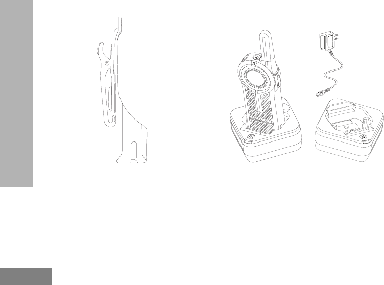
PACKAGE CONTENTS
• Radio
• Holster
• Lithium-Ion Battery
• Power Supply
• Quick Reference Guide
• Drop-in Tray Charger with Power Adapter
• Product Safety & RF Exposure Booklet

English
5
INTRODUCTION
For product-related questions, contact:
1-800-448-6686 or visit us at:
www.motorolasolutions.com/DLR

English
6
FCC LICENSING
INFORMATION
FCC LICENSING
INFORMATION
DLR Series business two-way radios operate in
the license-free 900 MHz ISM Band (902 – 928
MHz) and are subject to the Rules and
Regulations of the Federal Communications
Commission (FCC).
This device complies with part 15 of the FCC
Rules and RSS license-exempt of the Industry
Canada. Operation is subject to the following two
conditions: (1) This device may not cause harmful
interference, and (2) this device must accept any
interference received, including interference that
may cause undesired operation.
Changes or modifications not expressly approved
by Motorola may void the user’s authority granted
by the FCC/IC to operate this radio and should not
be made. To comply with FCC/IC requirements,
transmitter adjustments should be made only by or
under the supervision of a person certified as
technically qualified to perform transmitter
maintenance and repairs. Replacement of any
transmitter component (crystal, semiconductor,
etc.) not authorized by the FCC/IC equipment
authorization for this radio could violate FCC/IC
rules.
Note: Use of this radio outside the country where it
was intended to be distributed is subject to
government regulations and may be
prohibited.

English
7
BATTERIES AND CHARGERS
SAFETY INFORMATION
BATTERIES AND
CHARGERS SAFETY
INFORMATION
This document contains important safety and
operating instructions. Read these instructions
carefully and save them for future reference.
Before using the battery charger, read all the
instructions and cautionary markings on
• the charger,
• the battery, and
• the radio using the battery
1. To reduce risk of injury, charge only the
rechargeable Motorola-authorized batteries.
Other batteries may explode, causing personal
injury and damage.
2. Use of accessories not recommended by
Motorola may result in risk of fire, electric
shock, or injury.
3. To reduce risk of damage to the electric plug
and cord, pull by the plug rather than the cord
when disconnecting the charger.
4. An extension cord should not be used unless
absolutely necessary. Use of an improper
extension cord could result in risk of fire and
electric shock. If an extension cord must be
used, make sure that the cord size is 18AWG
for lengths up to 100 feet (30.48 m), and
16AWG for lengths up to 150 feet (45.72 m).
5. To reduce risk of fire, electric shock, or injury, do
not operate the charger if it has been broken or
damaged in any way. Take it to a qualified
Motorola service representative.
6. Do not disassemble the charger; it is not
repairable and replacement parts are not
available. Disassembly of the charger may
result in risk of electrical shock or fire.
7. To reduce risk of electric shock, unplug the
charger from the AC outlet before attempting
any maintenance or cleaning

English
8
BATTERIES AND CHARGERS
SAFETY INFORMATION
OPERATIONAL SAFETY
GUIDELINES
• Turn the radio OFF when charging battery.
• The charger is not suitable for outdoor use. Use
only in dry locations/conditions.
• Connect charger only to an appropriately fused
and wired supply of the correct voltage (as
specified on the product).
• Disconnect charger from line voltage by removing
main plug.
• The outlet to which this equipment is connected
should be nearby and easily accessible.
• In equipment using fuses, replacements must
comply with the type and rating specified in the
equipment instructions.
• Maximum ambient temperature around the power
supply equipment must not exceed 40°C (104°F).
• Power output from the power supply unit must not
exceed the ratings stated on the product label
located at the bottom of the charger.
• Make sure that the cord is located where it will
not be stepped on, tripped over, or subjected to
water, damage, or stress.
English
9
RADIO OVERVIEW
RADIO OVERVIEW
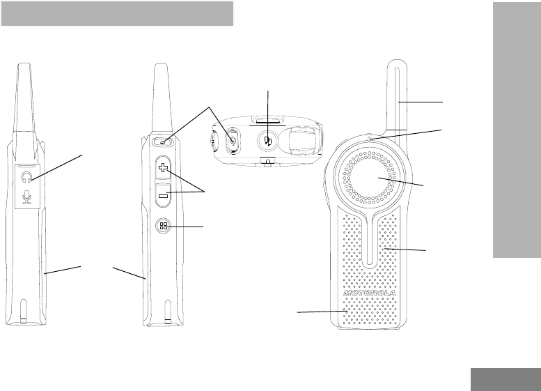
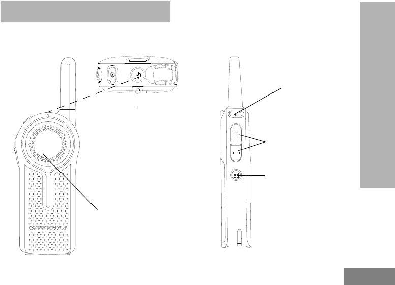
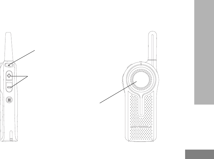
PARTS OF THE RADIO
Antenna
Volume/Up-Down
Control Buttons
Tx/Rx
Indicator
LED
Battery
PTT (Push-To-
Talk) Button
Power Button
Audio Accessory
Connector
Channel / Menu
Button Microphone
Top Button
Speaker

English
10
RADIO OVERVIEW
Power Button
Long press to turn the radio ON or OFF. Short
press to check battery status.
Top Button
The radio Top Button comes defaulted to
“Private Reply” feature.
Note: For more information regarding
programming the Top Button to other
features, refer to “Special Radio Call
Features” on page 49.
Volume Control (+/-) Button
Used to increase (+), decrease (-) or mute the
volume.
Audio Accessory Connector
Used to connect compatible audio accessories.
Microphone
Speak clearly into the microphone when
sending a message.
Antenna
For models DLR1020 and DLR1060 the
antennas are non-removable.
Tx/Rx Indicator LED
Used to indicate whether the radio is on
standby, receiving or transmitting.
Push-to-Talk (PTT) Button
To talk, press the PTT (Push to Talk) and WAIT
to hear the Talk Permit Tone (a quick double
beep) BEFORE you start speaking. Hold the
radio vertically 1 to 2 inches (2.5cm to 5cm)
from mouth when talking. Release the PTT to
listen.
Channel / Menu Button
In standard radio operation mode, the Channel/
Menu button comes defaulted to channel
function. To change channel, press the
Channel / Menu button and then Press the (+)
or (-) button to browse channels. Short press
the PTT button to exit.
When in Advanced Configuration Mode,
Channel / Menu button gives access and
allows navigation to set up special features.
English
11
RADIO OVERVIEW
The Lithium-Ion (Li-Ion) Battery
DLR Series comes with a Standard Capacity
Li-Ion battery. Other batteries may be available. For more information, see “Battery Features” on
page 12.
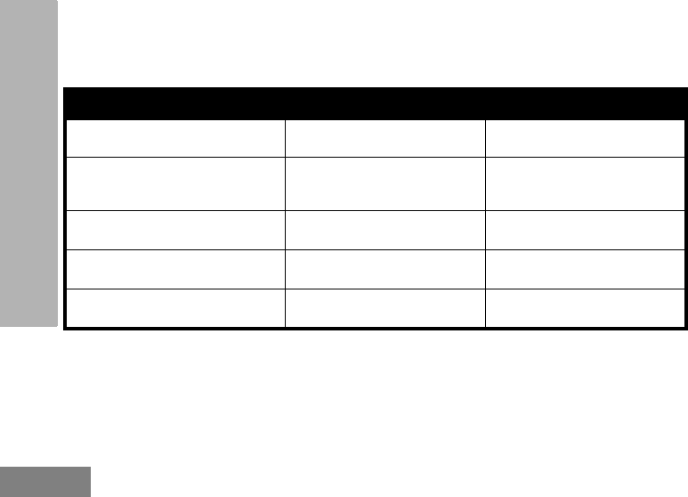
DLR Series Radio Specifications
The radio’s model is shown on the back of the radio and provides the following information:
Table 1: DLR Series Radio Specifications
Model Frequency
Band
Transmit
Power
(Watts)
Number of
Channels Antenna
DLR1020 ISM 900 MHz 1 2 Non-removable
DLR1060 ISM 900 MHz 1 6 Non-removable

English
12
RADIO OVERVIEW
BATTERY FEATURES
DLR Series radios provide standard
Lithium-Ion batteries.
Note: Batteries with different capacities and
operational life may be available in future.
About the Li-Ion Battery
The DLR Series radio comes equipped with a
rechargeable Li-Ion battery. This battery should
be fully charged before initial use to ensure
optimum capacity and performance.
Battery life is determined by several factors.
Among the more critical are the regular
overcharge of batteries and the average depth
of discharge with each cycle. Typically, the
greater the overcharge and the deeper the
average discharge, the fewer cycles a battery
will last. For example, a battery which is
overcharged and discharged 100% several
times a day, lasts fewer cycles than a battery
that receives less of an overcharge and is
discharged to 50% per day. Further, a battery
which receives minimal overcharging and
averages only 25% discharge, lasts even
longer.
Motorola batteries are designed specifically to
be used with a Motorola charger and vice
versa. Charging in non-Motorola equipment
may lead to battery damage and void the
battery warranty. The battery should be at
about 77°F (25°C) (room temperature),
whenever possible. Charging a cold battery
(below 50° F [10°C]) may result in leakage of
electrolyte and ultimately in failure of the
battery. Charging a hot battery (above 95°F
[35°C]) results in reduced discharge capacity,
affecting the performance of the radio.
Motorola rapid-rate battery chargers contain a
temperature-sensing circuit to ensure that
batteries are charged within the temperature
limits stated above.

English
13
RADIO OVERVIEW
Battery Recycling and Disposal
Li-Ion rechargeable batteries can be recycled.
However, recycling facilities may not be
available in all areas. Under various U.S. state
laws and the laws of several other countries,
batteries must be recycled and cannot be
disposed of in landfills or incinerators. Contact
your local waste management agency for
specific requirements and information in your
area. Motorola fully endorses and encourages
the recycling of Li-Ion batteries. In the U.S. and
Canada, Motorola participates in the
nationwide Rechargeable Battery Recycling
Corporation (RBRC) program for Li-Ion battery
collection and recycling.
Many retailers and dealers participate in this
program. For the location of the drop-off facility
closest to you, access RBRC's Internet web
site at:
www.rbrc.com
or call:
1-800-8-BATTERY
This internet site and telephone number also
provides other useful information concerning
recycling options for consumers, businesses
and governmental agencies.
English
14
RADIO OVERVIEW
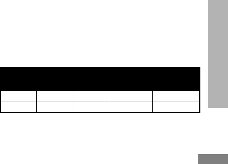
Installing the Lithium-Ion (Li-Ion) Battery
1. Slide the latch at the top of the battery door to the unlock position and lift up the battery door at the
center recess.
2. Align the battery contacts with the tabs in the battery compartment. Insert the contact side of the battery first,
then press the battery down to secure in place.
3. Put the battery door back on the radio. Slide the latch to the lock position .
1
2
English
15
RADIO OVERVIEW
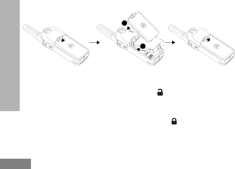
Removing the Lithium-Ion (Li-Ion) Battery
1. Turn OFF the radio.
2. Slide the latch at the top of battery door to the unlock position and lift up the battery door at the center
recess.
3. Pull on the battery removal tab until battery is disengaged from battery compartment.
4. Pull the battery away from radio.
English
16
RADIO OVERVIEW
Holster
1. Insert the radio into the base of the holster at an
angle. Press the radio against the back of the
holster until the hooks on the holster are
inserted in the top recesses of the battery.
2. To remove, using the top tab on the holster,
detach the hooks of the holster from the top
recesses of the battery. Slide the radio at an
angle and remove from the holster.
Power Supply, Adaptor and DLR Single Unit
Charger (SUC) Tray
The radio is equipped with one DLR Single Unit
Charger (SUC) Tray and one Power Supply
with Adaptor. See “Chargers” on page 113 for
more information.

English
17
RADIO OVERVIEW
Battery Life Information
When the Battery Save feature is set to ON (enabled by default), the battery life lasts longer. The
following table summarizes battery life estimations:
Note: Battery life is estimated based on 5% transmit / 5% receive / 90% standby standard duty cycle.
Battery Status Information
To check battery status, short press the Power button. DLR radio also announces battery level every
time it powers up.
Note: Battery save is ON by default.
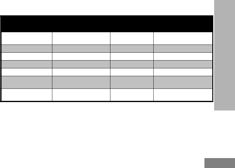
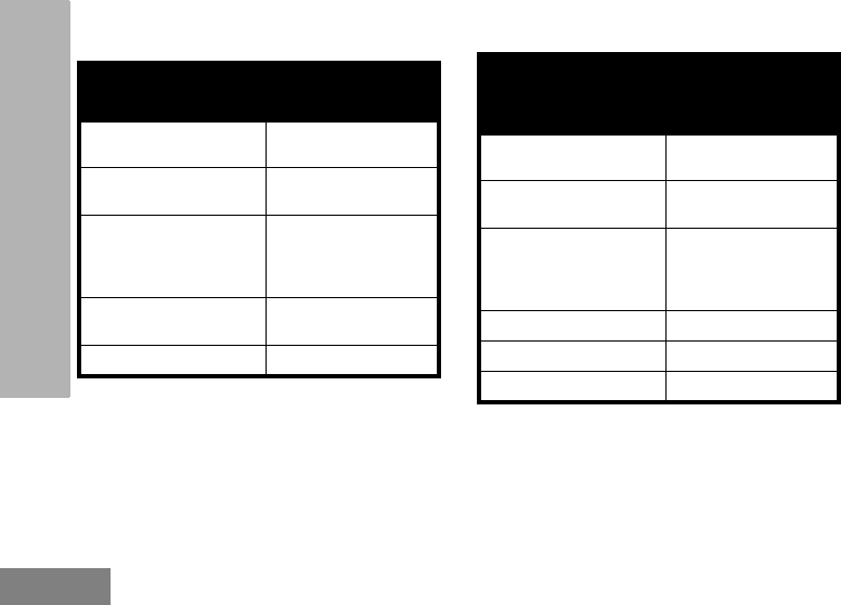
Table 2: Li-Ion Battery Life for DLR1020 and DLR1060
Battery Type Battery Save OFF Battery Save ON
Standard 10.0 – 12.0 Hours Up to 14 Hours
Table 3: Battery Status Information
Battery Status Battery Level Voice Prompt or Tone
Battery High 100% – 71% “Battery level high”
Battery Medium 70% – 41% “Battery level medium”
Battery Low 40% – 11% “Battery level low”
Battery Critical 10% – 0% “Battery level critical”
Battery Shutdown 0% Shutdown beeps
English
18
RADIO OVERVIEW
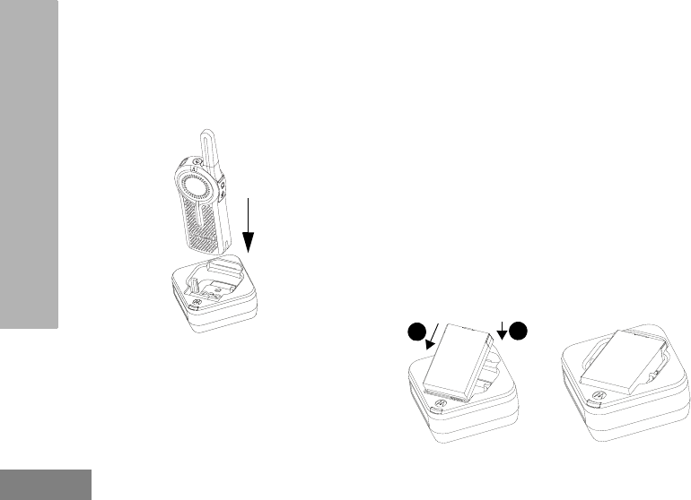
ATTENTION!
Always turn off the radios prior to charging.
Radios charge the best of room temperature.
Charging with the Drop-in Tray
Single Unit Charger (SUC)
The DLR Series radio comes with a Standard
Power Supply and DLR SUC tray.
1. Place the DLR SUC tray on a flat surface.
2. Insert the connector of the power supply into the
port on the side of the DLR SUC tray.
3. Plug the AC adaptor into a power outlet.
4. Turn the radio “OFF”.
5. Insert the radio into the tray with the front of the
radio facing the front of the charger, as shown.
Make sure the radio is securely inserted all the
way into the charger and the RED LED
illuminates to indicate that the battery is
charging. See “DLR Series Charger LED
Indicators” on page 21 for more information.
Note: When charging a battery attached to the
radio, turn the radio OFF to ensure a full
charge. See “Operational Safety Guidelines”
on page 8 for more information.
Charging A Stand-Alone Battery
12

English
19
RADIO OVERVIEW
To charge a battery, insert the battery into the
charger’s pocket by:
1. Aligning the raised tab on each side of the
battery with the corresponding groove on each
side of the charger pocket.
2. Pressing the battery toward the rear of the
pocket.
3. Sliding the battery into the charger pocket,
ensuring complete contact between the charger
and battery contacts.
4. When the battery is properly seated in the
pocket, the charger indicates the Battery Level
status as shown in Table 6. The RED LED
illuminates to indicate that the battery is
charging rapidly.
5. The LED changes to a STEADY GREEN light to
indicate that the battery is nearly or fully
charged.
Estimated Charging Time
The following table provides the estimated
charging time of the battery. For more
information, see “Battery” on page 113.
Table 4: Motorola Authorized Batteries
Part Number Description
HKNN4013_ Li-Ion Battery 1800mAh
Table 5: Battery Estimated Charging Time
Charging
Solutions
Estimated Charging
Time
Standard Battery
Standard ≤3.50 Hours
English
20
RADIO OVERVIEW
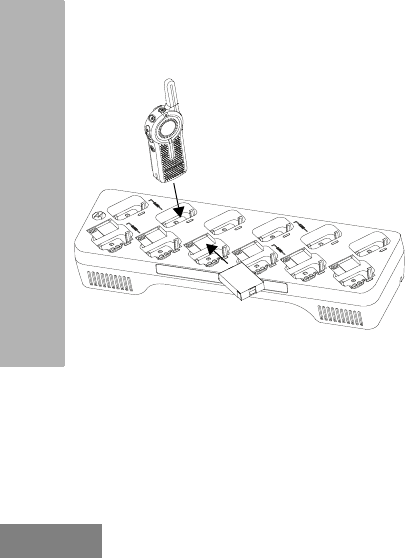
Charging a Radio and Battery using
a DLR 12-Pocket Multi Unit-Charger
- MUC (Optional Accessory)
The DLR 12-Pocket Multi-Unit Charger (MUC)
allows drop-in charging of up to 12 radios or up
to 6 radios and 6 stand-alone batteries.
Batteries can be charged with the radios or
removed and placed in the MUC separately.
Each of the 12 charging pockets can hold a
radio (with or without the Holster) or battery, but
not both.
1. Place the Multi-Unit Charger on a flat surface.
2. Insert the power cord plug into the MUC’s dual
pin connector at the bottom of the MUC.
3. Plug the power cord into an AC outlet.
4. Turn the radio OFF.
5. Insert the radio or battery into the charging
pocket with the radio or battery facing away
from the contacts.
Note:
• This Multi-Unit Charger clones up to 2 radios (2
Source radios and 2 Target radios). Refer to
“Cloning with a Multi-Unit Charger (MUC)
(Optional Accessory)” on page 97 for more
information.
• More information on the Multi-Unit Charger
operation is available in the Instruction Sheets
provided with the MUC. For more information on
the parts and their part numbers, refer to Chapter
“Accessories” on page 113.
English
21
RADIO OVERVIEW
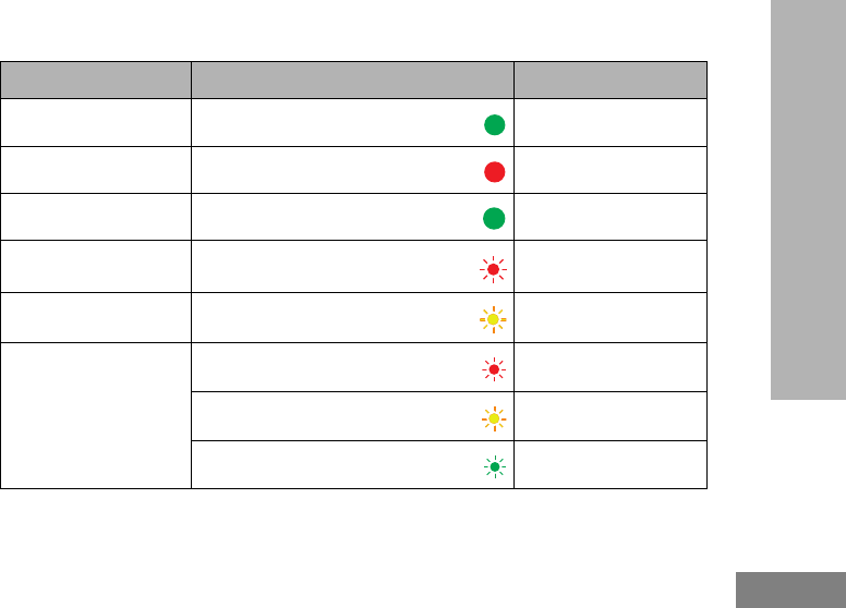
DLR Series Charger LED Indicators
(*) Normally, re-positioning the battery pack will correct this issue.
(**) Battery temperature is too warm or too cold or wrong power voltage is being used.
Table 6: Charger LED Indicator
Status LED Status Comments
Power On Green for approx. 1 sec
Charging Steady red
Charged Steady green
Error (*) Red fast flash
Standby (**) Amber slow flash
Battery Level Status
Flash red 1 time Battery low
Flash amber 2 times Battery medium
Flash green 3 times Battery high

English
22
RADIO OVERVIEW
If there is NO LED indication:
1. Check that the radio, or stand-alone battery, is inserted correctly.
2. Ensure the power supply is plugged into an appropriate AC outlet. (for DLR Single Unit Charger (SUC) Tray
only).
3. Ensure the cable is plugged securely into the charger socket (for DLR Single Unit Charger (SUC) Tray
only).
4. Ensure the power cord is plugged securely into the charger socket with an appropriate AC outlet and there is
power to the outlet (for DLR 12-Pocket Multi Unit Charger Tray only)
5. Confirm that the battery used with the radio is Motorola Solutions authorized batteries listed in Table 4.

English
23
RADIO OVERVIEW
DLR Radios and Charger Compatibility
Note: Although DLR Series and CLS Series chargers are compatible, DLR and CLS radios operate in different
frequency bands and will not communicate with each other.
Table 7: DLR and CLS Chargers Compatibility
Chargers
Charging Compatibility
DLR radio
with inserted
battery
DLR
standalone
batteries
CLS radio
with inserted
battery
CLS
standalone
batteries
DLR SUC
DLR MUC
CLS SUC
CLS MUC

English
24
RADIO OVERVIEW
Notes
English
25
GETTING STARTED
GETTING STARTED
For the following explanations, refer to “Parts Of The Radio” on page 9.
RADIO BASIC OPERATION
(+) / (-) Buttons
Press up and down to
adjust volume.
PTT (Push-To-Talk)
Button
Push PTT button firmly.
Wait for TPT Tone. Talk
into Microphone(*)
ON / OFF Button
Long press to turn ON
and OFF. Short press to
check battery status.
Channel / Menu Button
Press button to hear current
channel.
Subsequent press of (+) / (-)
Buttons changes channels.
Press PTT button to exit
channel browsing
Top Button
Press the Top Button to queue
up for Private Reply (while
someone is talking in your
channel).
Press PTT button to Reply
Privately to that last person
who spoke.
(*)Ensure microphone is positioned 1 to 2 inches (2.5 to 5 cm) away from mouth

English
26
GETTING STARTED
TURNING RADIO ON/OFF
To turn ON the radio, press and hold the Power
button until the radio plays the power up tone
and the standby light begins to blink.
Note: By default, when radio is turned ON, it
announces the current channel name and
battery status.
To turn the radio OFF, press and hold the
Power button (~3 seconds) until the radio Tx/
Rx Indicator LED turns OFF and power down
tone is heard.
ADJUSTING VOLUME
Press the (+) button to increase the volume, or
the (-) button to decrease the volume.
To mute, press and hold the (-) button (~2
seconds) until you hear the voice
announcement “Mute”.
Note: Radio mute means setting the volume to the
lowest level. (This is to prevent the user
from forgetting to unmute the radio.)
To maximize volume, press and hold the (+)
button (~2 seconds). The volume will fast scroll
up to maximum volume. You will hear the
volume beeps increment as the volume
increases.
Notes: Do not hold the radio too close to the ear
when the volume is high or when adjusting
the volume.
There are 16 increments of volume.
As the (+) / (-) buttons are pressed, you will
hear a beep at the current volume level. If
device is receiving during volume
interaction, received audio will be heard at
the new volume instead of beeps.
When using radio with earpiece, make sure to
adjust the radio volume to the lowest volume
before putting on the earpiece. Refer to
“Acoustic Safety” on page 3. Use only Motorola
approved accessories. Refer to “Audio
Accessories” on page 113 for more information.

English
27
GETTING STARTED
CHECKING BATTERY STATUS
To check the battery status, short press the
power button. Refer to “Battery Status
Information” on page 17 for more information.
Note: The four levels available for battery status
are : High, Medium, Low and Critical.
TRANSMITTING AND RECEIVING
• To receive, listen through the speaker.
• To respond or to talk, press the PTT (Push to
Talk) and WAIT to hear the Talk Permit Tone
(TPT) BEFORE you start speaking. Hold the
radio vertically 1 to 2 inches (2.5cm to 5cm)
from mouth when talking. Release the PTT to
listen.
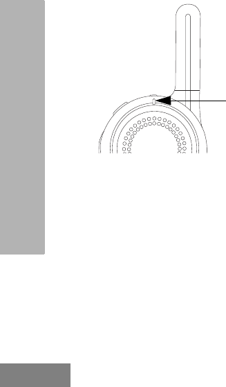
• The Tx/Rx Indicator blinks slowly RED when
on standby. When the radio is transmitting, the
Tx/Rx Indicator is solid RED.
• When the radio is receiving, the Tx/Rx
Indicator LED blinks RED quickly.
IMPORTANT:When talking on the radio, make sure
not to release the PTT button at any
given time. Whether you are
transmitting using the PTT button or
using an in-line PTT on the earpiece
accessory, always ensure the PTT
button is pressed firmly until the
transmission is finished. Releasing the
PTT button while transmitting and trying
to immediately press the PTT button
again causes the radio to give a loud
denial tone. Wait for 2 seconds and
press PTT again to continue speaking.
If you press the PTT button to transmit
and a busy tone is received instead of a
TPT, this means the channel is either
not available, busy or there are no users
reachable within transmission range.
Talk Permit Tone (TPT)
TPT is a quick distinctive double beep tone that
sounds after the user presses the PTT button,
indicating the channel is free to talk. TPT is
useful in ensuring orderly communications by
preventing radios from transmitting over
ongoing conversations.
Always wait to hear the TPT before starting to
speak to ensure your words are not cut off.
English
28
GETTING STARTED
Talking to a Group in a Channel
To transmit, press the PTT (Push to Talk) and
WAIT to hear the TPT (Talk Permit Tone)
BEFORE you start speaking.
BROWSING / SELECTING A CHANNEL
To select a channel, press the Channel / Menu
button until the voice announcement “Channel
<Number>, to change press + or -” is heard.
Press (+) or (-) buttons to select the desired
channel. An audible voice indicates the
selected channel.
To exit Channel Change, press the PTT button
or wait for the radio Channel / Menu timer to
expire.
PRIVATE REPLY
DLR radio comes with the Top Button
configured to Private Reply Feature i.e. when
you hear someone talking on the radio, push
the Top Button to queue for Private Reply
function (Top Button LED indicator blinks
orange). Once the person finishes talking,
press the PTT button to Reply Privately to that
person (Top Button LED illuminates solid
orange). Voice prompts and tones will guide
you on Private call status. For more details on
how to use this feature, refer to “Special Radio
Call Features” on page 49.
TOP BUTTON OPTIONS
The Top Button comes pre-programmed with
the Private Reply Feature. Top Button can be
configured also to allow other different call
features such as: Page All Available, Call
Solid Red
Tx/Rx
Indicator
LED when
transmitting

English
29
GETTING STARTED
Available, Direct Call and Mute. It can also be
disabled. For more details on how to configure
the Top Button refer to “Advanced
Configuration Mode” on page 33.
TALK RANGE
For a group of DLR radios to be able to
communicate, they need to be on the same
channel and have the same radio PROFILE ID
number. All radios come by default
programmed to PROFILE ID number “0000”
1. Channel: Current channel that the radio is
using, depending on radio model.
2. PROFILE ID Number: ALL the radios in your
fleet (independent of the channels that users
are assigned to) should use the SAME
PROFILE ID. It is also VERY IMPORTANT TO
CUSTOMIZE THE PROFILE ID number in
order to avoid interference from other users
using the default "0000" number.
In order to customize your radio fleet PROFILE
ID, choose a 4 digit number and enter it using
the radio Advanced Configuration Mode (Turn
off the radio, Press the PTT, (+) and Power
buttons simultaneously and hold until radio
announces "Programming Mode". Follow voice
prompts). For more information, refer to the
“Advanced Configuration Mode” on page 33.
DLR AND DTR RADIOS COMPATIBILITY
DLR and DTR radios are based on the same
digital radio technology and can be used in
mixed fleets of DLR and DTR radios. Out of the
box, DLR and DTR radios will communicate
using the factory default settings.
TALK RANGE
Model
Industrial Multi-Level
Inside steel/
concrete Industrial
buildings
Inside multi-
level buildings
ISM
900 MHz Up to 300,000 Sq. Ft. Up to 20 Floors

English
30
GETTING STARTED
If you have DTR radios with customized
settings and/or private groups, and need to add
DLR radios, make sure to use the DLR CPS
software(*) in order to create a compatible
configuration in the DLR radios. The same
applies if DTR radios are to be added to an
existing DLR radio fleet. For more details on
DTR and DLR compatibility please contact your
Motorola point of sale.
For questions or comments related to this
product, please contact Motorola:
1-800-448-6866
Note: (*) DLR CPS software is available for free
download at
www.motorolasolutions.com/DLR
English
31
GETTING STARTED
RADIO STATUS
Radio Status Front LED Indicator Top Button LED
Indicator Voice Prompt or Tone
Power Up Solid Red for 2 seconds OFF “Battery Level <Level>,
Channel <Number>”
Power Off Solid Red for 2 seconds OFF Power Off chirps
Fatal Error at Power up Double Blink Red Single Blink Orange Not Available
Channel Busy Not Available OFF Busy tone
‘Idle’ Mode Heartbeat Red OFF Not Available
Transmit (Tx) (standard
group call) Solid Red OFF Not Available
Receive (RX) (standard
group call) Fast Red Heartbeat OFF Not Available

English
32
GETTING STARTED
Notes
English
33
ADVANCED CONFIGURATION
MODE
ADVANCED CONFIGURATION MODE
The DLR Advanced Configuration Mode allows you to configure special settings in your radio
without the need of programming cables or additional software.
Advanced Configuration Mode gives access to customize the following features:
• PROFILE ID Number,
• Maximum Channels,
• Top Button,
• Microphone (MIC) Gain, and
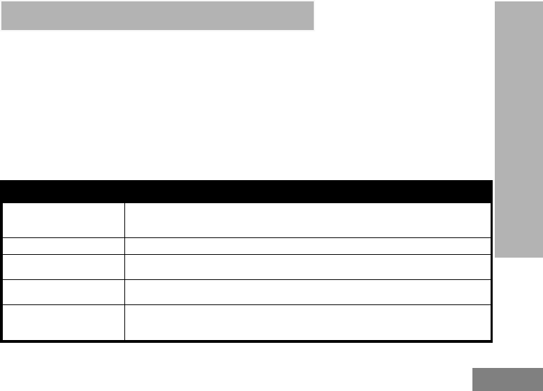
• Home Channel. Table 1: Advanced Configuration Mode Features
Feature Description
PROFILE ID Number
Choose a 4 digit number (0000 – 9999) as your radio PROFILE ID Number.
Customize the PROFILE ID Number to ensure intereference free / private
communications.
Maximum Channels Choose the maximum number of channels you want to allow for your radio.
Top Button Set the Top Button with one of the following feature: Private Reply, Direct Call(*),
Call All Available, Page All Available, Mute, Disabled.
MIC Gain Choose between High, Medium or Low MIC Gain to adjust the radio microphone
sensitivity level to fit different users or noise environments.
Home Channel
Choose the channel you want to designate as your main channel. Everytime you
change to a different channel and no activity is detected from the channel, the radio
reverts back to your home channel.
(*) Only if enabled via CPS

English
34
ADVANCED CONFIGURATION
MODE
ENTERING ADVANCED CONFIGURATION MODE
To enter the Advanced Configuration Mode, power UP using the ON / OFF button while pressing the
PTT and (+) buttons simultaneously.
(+) Button
PTT (Push-To-Talk)
Button
ON / OFF Button
Power UP using the ON / OFF
button while pressing the PTT
and (+) buttons simultaneously
to enter Advanced Configuration
Mode
English
35
ADVANCED CONFIGURATION
MODE
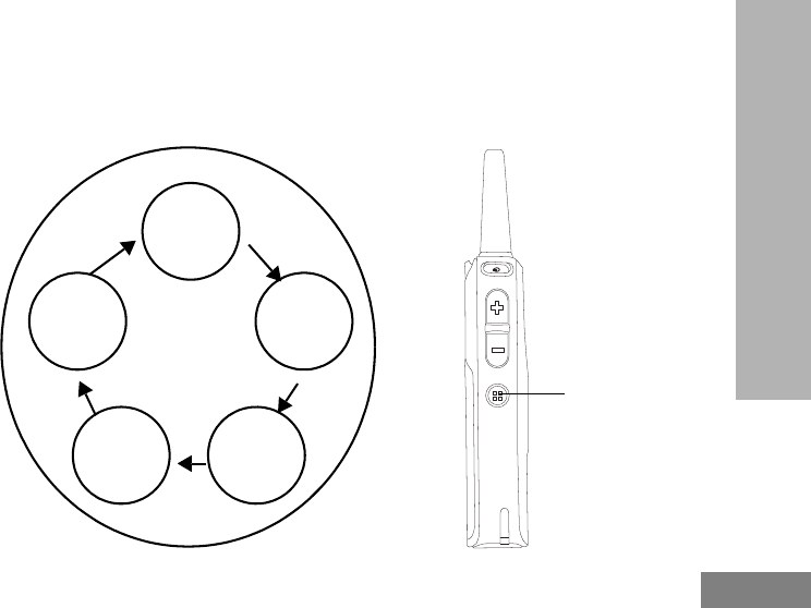
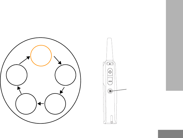
BROWSING ADVANCED CONFIGURATION OPTIONS
Upon entering Advanced Configuration Mode, radio plays voice prompt “Programming Mode. Press
Menu to continue”. Press Channel / Menu button to cycle through the Advanced Configuration
options.
Note: Long press the PTT button at any time to exit the Advanced Configuration Mode altogether.
Channel / Menu Button
Press to cycle through
the Advanced
Configuration options.
“Programming Mode.
Press Menu to continue”.
PROFILE ID
Number
Maximum
Channel
Top Button
MIC Gain
Home
Channel
English
36
ADVANCED CONFIGURATION
MODE
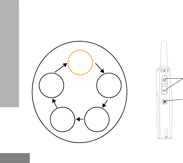
PROFILE ID Number
PROFILE ID Number – Current Value
Once you press the Channel / Menu button, the radio announces the current PROFILE ID
Number(*) and prompts you to change it. Press (+) or (-) button to enter the PROFILE ID Number
sub-menu. Alternatively, press the Channel / Menu button to continue to the next Advanced
Configuration option.
Channel / Menu
Button
Press to continue to
the next Advanced
Configuration option
“Current Profile ID
<Digit 1, Digit 2, Digit 3,
Digit 4> to change,
press plus or minus”.
PROFILE
ID Number
Maximum
Channel
Top Button
MIC Gain
Home
Channel
(+) / (-) Buttons
Press to enter the
PROFILE ID Number
sub-menu
(*) PROFILE ID Number default is “0000”. Change it to avoid interferences and improve privacy.
English
37
ADVANCED CONFIGURATION
MODE
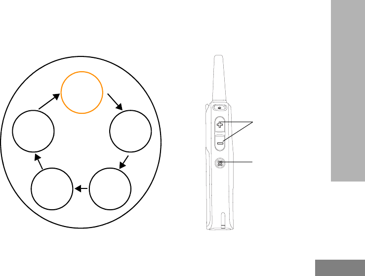
PROFILE ID Number – Changing values
Once you press either the (+) or (-) to enter the PROFILE ID Number sub-menu, the radio
announces the first digit number value and prompts you to change it(*). Press (+) or (-) button again
to change the first digit number. Press Channel / Menu button to continue to the next digit.
Channel / Menu Button
Press to continue to the
next digit
“First digit <number>. To
change press plus or
minus”.
PROFILE
ID Number
Maximum
Channel
Top Button
MIC Gain
Home
Channel
(+) / (-) Buttons
Press (+) or (-) button to
change the first digit
number
(*) There is 10,000 options of PROFILE ID Number to choose from (0000 – 9999).
English
38
ADVANCED CONFIGURATION
MODE
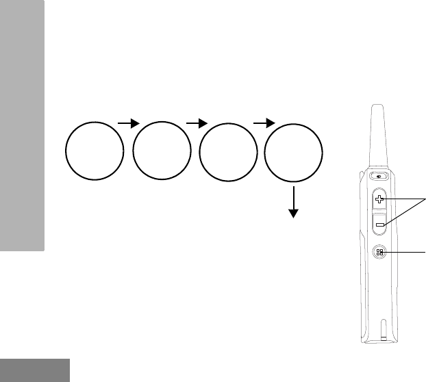
PROFILE ID Number – Sub-menu
When you press (+) or (-) button to change the current digit, radio announces the value. Press
Channel / Menu to continue to the next digit. Once in Digit 4, press Channel / Menu button again to
continue to the next Advanced Configuration option.
Note: DLR radio gives you the option to move forward through the 4 digits with the Channel / Menu button.
There is no option to move backward through the 4 digits of PROFILE ID Number.
Channel / Menu Button
Press to continue to
next digit. Once in Digit
4, press button again to
continue to the next
Advanced Configuration
option
“Zero, one, two,
three...nine, zero..”.
Digit 1
(+) / (-) Buttons
Press to change the
current digit value
Digit 2 Digit 3 Digit 4
Press Channel / Menu button
to continue to the next
Advanced Configuration option
English
39
ADVANCED CONFIGURATION
MODE
PROFILE ID Number – Value Modification Confirmation
Once you have set the 4 digit PROFILE ID Number, the radio announces the entire new PROFILE
ID Number value. Press Channel / Menu button to continue to the next Advanced Configuration
option or hold down the PTT button to exit the Advanced Configuration Mode.
Note: If the 4 digit PROFILE ID number set is not the numbers wanted upon moving to the next Advanced
Configuration option, press the Channel / Menu button and cycle through the Advanced Configuration
options until you are back at the PROFILE ID Number option to change the value.
Channel / Menu Button
Press to continue to the
next Advanced
Configuration option
“Profile ID saved as
<Digit 1, Digit 2, Digit 3,
Digit 4>. Press Menu to
continue ”.
PROFILE
ID Number
Maximum
Channel
Top Button
MIC Gain
Home
Channel
English
40
ADVANCED CONFIGURATION
MODE
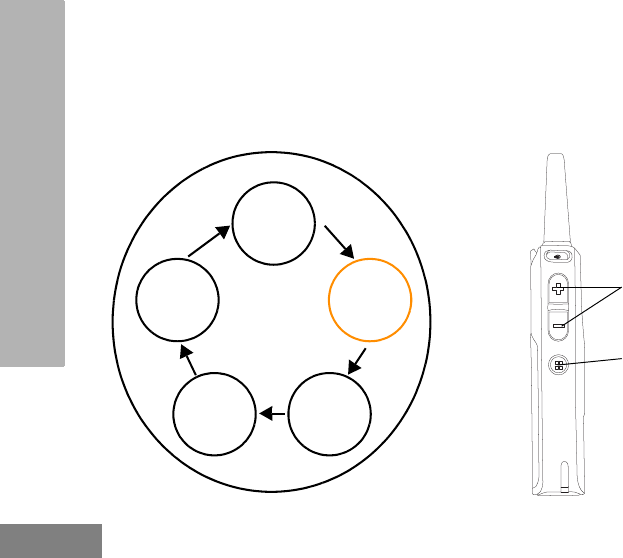
Maximum Channels
Press the Channel / Menu button until the radio announces the current maximum number of
channels and prompts you to change it. Press (+) or (-) button to change the number of channels(*).
Press Channel / Menu button to continue to the next Advanced Configuration option.
Note: The maximum number of channels you can set up in your radio is limited by the radio model. DLR1060
has maximum 6 channels and DLR1020 has maximum 2 channels.
Channel / Menu
Button
Press to continue to the
next Advanced
Configuration option
“Maximum channels
<number>. To change,
press plus or minus ”.
PROFILE
ID Number
Maximum
Channel
Top Button
MIC Gain
Home
Channel
(+) / (-) Buttons
Press to change the
number of channels
(*) Maximum number channels allowed by default is the maximum number of channels your radio model has.
English
41
ADVANCED CONFIGURATION
MODE
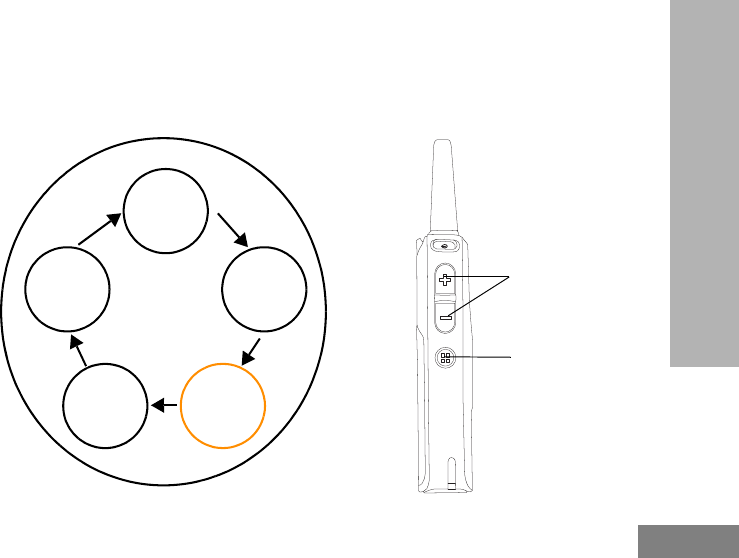
Top Button
Top Button – Current Feature
Press the Channel / Menu button until the radio announces the current Top Button feature and
prompts you to change. Press (+) or (-) button to enter the Top Button sub-menu. Alternatively, press
Channel / Menu button to continue to the next Advanced Configuration option.
Channel / Menu Button
Press to continue to the
next Advanced
Configuration
“Programmable Button
<Top Button Feature>. To
change, press plus or
minus”.
PROFILE
ID Number
Maximum
Channel
Top Button
MIC Gain
Home
Channel
(+) / (-) Buttons
Press to enter the Top
Button sub-menu
English
42
ADVANCED CONFIGURATION
MODE
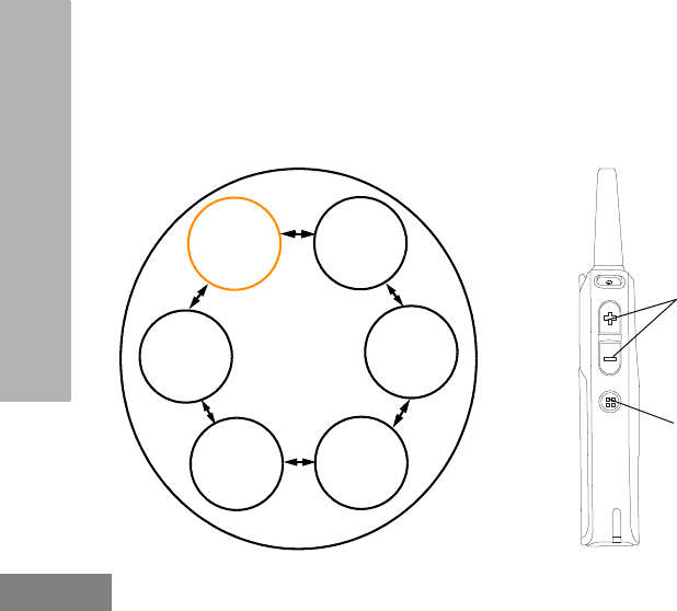
Top Button – Sub-menu options
Once you press the (+) or (-) button to enter the Top Button sub-menu, you can browse back and
forward the different Top Button options using the (+) or (-) button. Radio will guide with voice
prompts as you navigate through the features. Press Channel / Menu button to continue to the next
Advanced Configuration option.
Note: In order to use the Direct Call option, it must be enabled via CPS beforehand. Otherwise Top Button
sounds an error tone even if you choose the option in the this menu.
“<Top Button feature>”.
Private
Reply
Direct
Call(*)
Call All
Available
Page All
Available
Disabled
(+) / (-) Buttons
Browse back and
forward the different
Top Button options
using the (+) or (-)
button
Mute
Channel / Menu
Button
Press to continue to the
next Advanced
Configuration option
(*) Direct Call feature is only available if it has been previously enabled via CPS.
English
43
ADVANCED CONFIGURATION
MODE
MIC Gain
Press the Channel / Menu button until the radio announces the MIC Gain setting and prompts you to
change it. There is three MIC Gain settings to choose from – Low, Medium, High. The default MIC
Gain value is “Medium”. Press the (+) or (-) button to change MIC Gain settings. Press Channel /
Menu button to continue to the next Advanced Configuration option. MIC Gain should only be
changed if other users complain that the volume from this radio is too low or too high. The default
Medium setting should be appropriate for most users, so it can be left unchanged.
Channel / Menu Button
Press to continue to the
next Advanced
Configuration option
“MIC Gain <MIC Gain
level>. To change, press
plus or minus”.
PROFILE
ID Number
Maximum
Channel
Top Button
MIC Gain
Home
Channel
(+) / (-) Buttons
Press to change MIC
Gain settings
English
44
ADVANCED CONFIGURATION
MODE
Home Channel
Press the Channel / Menu button until the radio announces the Home Channel setting and prompts
you to change it. There is two Home Channel settings to choose from – Disabled or Channel
number (or channel name if alias was set up via CPS). The default setting of Home Channel is
“Disabled”. Press Channel / Menu button to cycle back to the first Advanced Configuration option –
PROFILE ID Number.
Note: When Home Channel is enabled, if no activity is detected from a channel for 7 seconds (CPS
programmable), the radio reverts back to the Home Channel, so this feature may not be appropriate for
users who need to frequently change channels throughout the day
Channel / Menu
Button
Press to cycle back to
the first Advanced
Configuration option
“Home Channel <Home
Channel setting>. To
change, press plus or
minus”.
PROFILE
ID Number
Maximum
Channel
Top Button
MIC Gain
Home
Channel
(+) / (-) Buttons
Press to change Home
Channel settings
English
45
ADVANCED CONFIGURATION
MODE
RESETTING TO FACTORY DEFAULTS
In order to reset your radios to the original factory defaults, power UP using the ON / OFF button
while pressing PTT, (-) and (+) buttons simultaneously. Radio sounds resetting beeps and the voice
prompt announces “Battery Level <battery level>, Channel <channel name>”.
(+) / (-) Buttons
ON / OFF Button
PTT (Push-To-Talk)
Button
Power UP using the ON /
OFF button while pressing
the PTT, (+) and (-) buttons
simultaneously to reset to
factory defaults.
English
46
ADVANCED CONFIGURATION
MODE
Radio Factory Default Settings
Table 2: Radio Basic Feature Defaults
Radio Basic
Feature Default
Power up
announcement Battery Status and
Channel Name
Quick press ON / OFF
button Battery Status
Number of channels
Set to maximum
number of channels
supported by the
radio model
Channel / Menu button Channel change
only
Top Button feature Private Reply
Table 3: Radio Advanced Configuration
Mode Defaults
Radio Advanced
Configuration
Mode Default
PROFILE ID Number
lock OFF
Radio PROFILE ID
Number 0000
Maximum Channels
Set to maximum
number of channels
supported by the
radio model
Direct Call OFF
MIC Gain Medium
Home Channel Disabled
English
47
ADVANCED CONFIGURATION
MODE
For all other radio defaults, please refer to the
CPS.
Table 4: Radio Special Mode Defaults
Radio Special
Mode Default
Enable restore Factory
Default reset ON
Enable Advanced
Configuration Mode ON
Enable Cloning Mode ON

English
48
ADVANCED CONFIGURATION
MODE
Notes

English
49
SPECIAL RADIO CALL
FEATURES
SPECIAL RADIO CALL
FEATURES
PRIVATE REPLY
The DLR radio Top Button is programmed by
default as “Private Reply”. Push the Top Button
to capture the radio ID of the person currently
talking to your group and right after the
transmission is over, push the PTT button to
talk privately to that person.
Private Reply helps users free the radio
channel from unnecessary back and forward
chatter by allowing two people to instantly
connect privately after a group transmission is
over.
Application Example
The use of this feature reduces the need for
phone extensions or cell phone calls to talk
privately. Simply call on the radio the name of
the person you want to talk to privately. When
he or she responds to you, push the Private
Reply button (Top Button) and then press the
PTT button to initiate the one to one private
conversation.
English
50
SPECIAL RADIO CALL
FEATURES
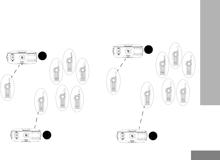
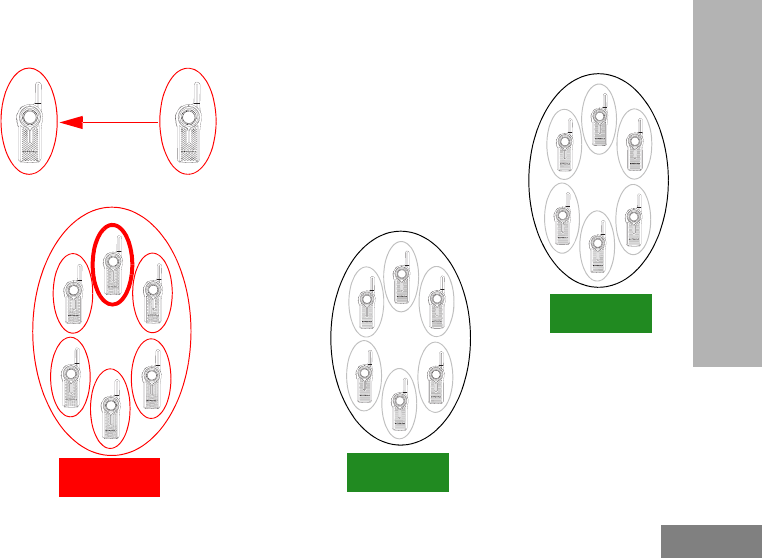
How Private Reply Works
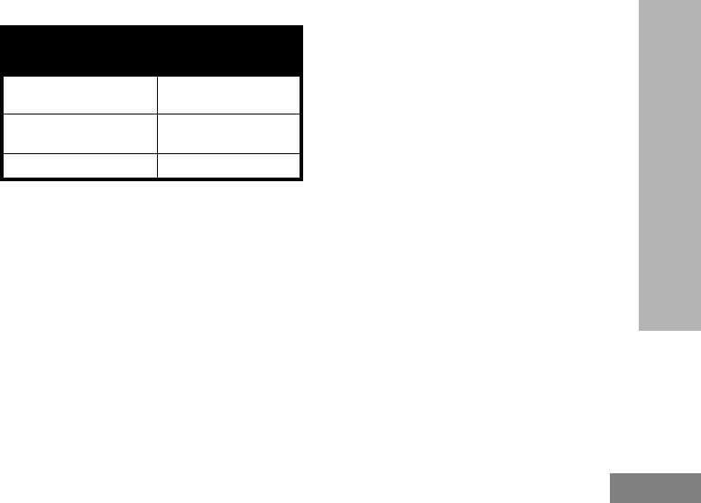
1. User B is talking to a group of radios
2. User A wants to talk to User B privately and
presses the Top Button to queue up.
Note: Long pressing the Top Button a second time
cancels the Private Reply queue.
Group call in
progress
A
B
A
B
A
English
51
SPECIAL RADIO CALL
FEATURES
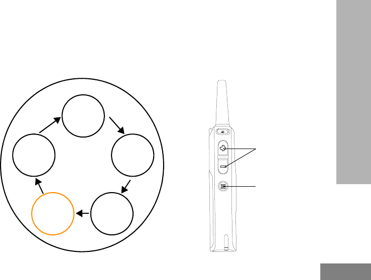
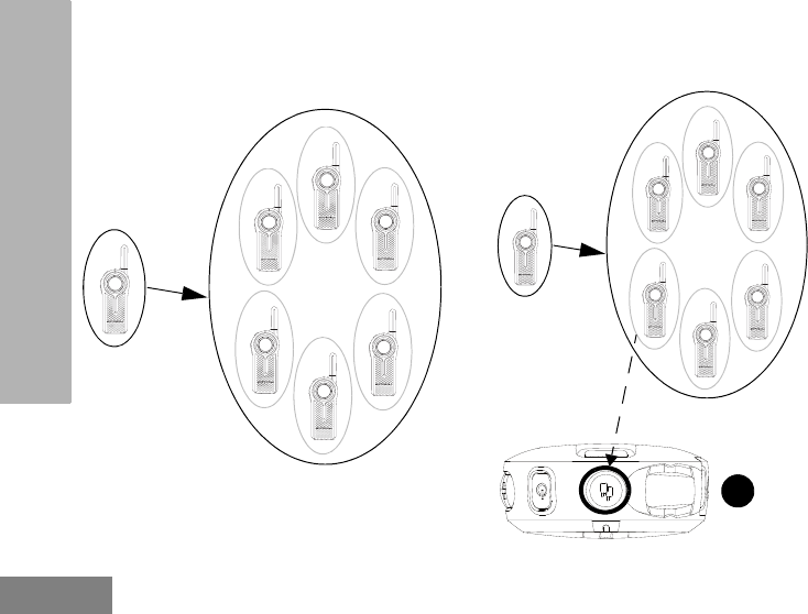
3. User A radio plays voice prompt “Private Reply”
and the Top Button starts blinking orange,
showing user A is in queue waiting to talk
privately to User B.
4. User B finishes talking to the Group while User
A radio is still blinking orange indicating it is in
queue for Private Reply call.
A
B
A
In queue for Private
Reply “Private Reply”
A
B
A
In queue for Private
Reply
English
52
SPECIAL RADIO CALL
FEATURES
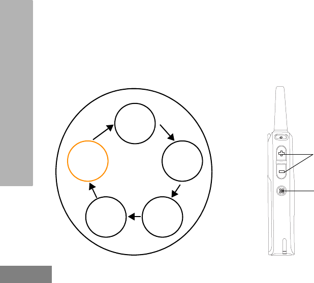
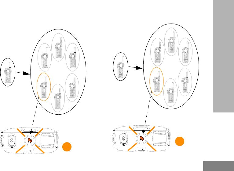
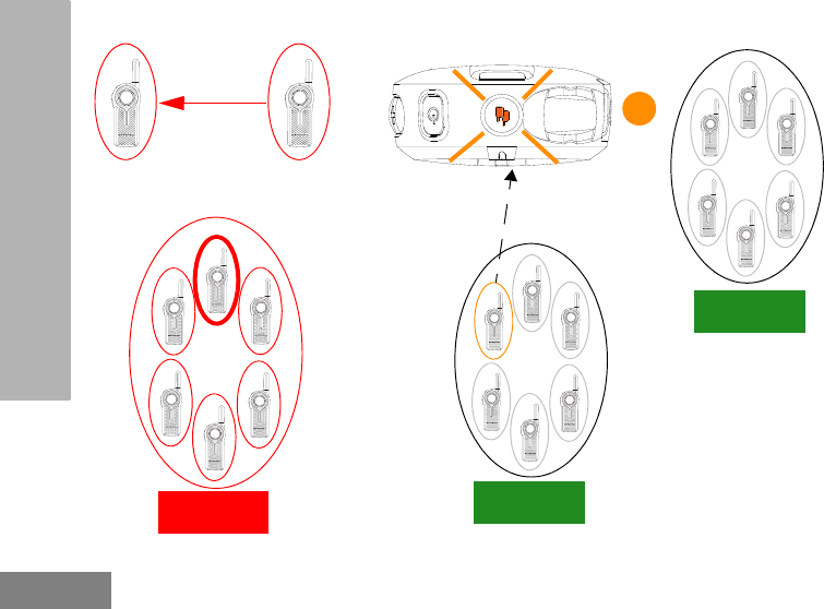
5. User A presses PTT button to talk privately to
User B. The Top button LED indicator for both
radio A and radio B illuminate solid orange.
User B hears radio voice prompt “Private” and
radio plays a distinctive Private TPT.
6. Whenever user A or B presses the PTT button
to reply back, they are talking privately to each
other. Nobody else hears them. Radio plays a
distinctive Private TPT.
A
B
A
Private Call in
progress
B
“Private”
A
B
A
Private Call in
progress
B
English
53
SPECIAL RADIO CALL
FEATURES
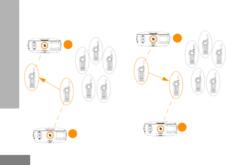
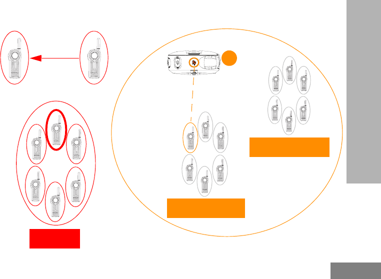
7a. If either one of the radio users takes too long to
push the PTT button and reply back, (the
default “Private Hang Time” is 7 seconds), the
radio times out and ends the private
communication with voice prompt “Private
Over” on both radios A and B. The TOP Button
LED indicator goes OFF.
7b. Radio user A (who initiated the Private Call),
can also end the call at any time by Long
pressing the Top Button. The radio plays voice
prompt “Private Over” on both radio A and B to
indicate that the private call is over. The TOP
button LED indicator turns OFF.
A
B
A
“Private Over”
B
“Private Over”
A
B
A
“Private Over”
B
“Private Over”
English
54
SPECIAL RADIO CALL
FEATURES
8. Radio user A and B join back the group
transmission in their channel once the private
call ends.
Note: You can set the “Private Hang Time” and
“Group Hang Time” to different values using
the CPS.
A
B
English
55
SPECIAL RADIO CALL
FEATURES
Private Reply Status Indicator
Notes: Private Reply times out after 7 seconds of inactivity (no transmissions detected). Voice prompt “Private
Over” will be heard by both users involved in the private call.
(*) This notification occurs only once in the beginning of the call.
Table 1: Private Reply Status Indicator
Private Reply Status Top Button LED Indicator Voice Prompt or Tone
Private Reply request in queue
(initiated using Top Button press) –
Initiator party Blink Orange “Private Reply”
Private conversation initiated
(using the PTT button) – Receiver
party Solid Orange Private TPT
Private Call notification(*) –
Receiver party Solid Orange “Private”
Private conversation in progress –
Both parties Solid Orange Private TPT
End of private conversation – Both
parties Off “Private Over”

English
56
SPECIAL RADIO CALL
FEATURES
DIRECT CALL
The Direct Call Feature allows a user to call
another pre-determined user that has been
mapped into the radio Top Button one-on-one
privately (this feature needs to be
pre-programmed via CPS*). Users also have
the option to assign the Direct Call feature to
any radio channel instead of the Top Button.
This allows the radio Top Button to be available
for other radio features (e.g.: Private Reply or
Mute) and Direct Call to be set up in a special
channel. (You can set up different direct calls in
different channels).
Note: In order to set up the Direct Call function for
the first time in your radio, (either Top Button
or to a specific channel ) you need to use
the CPS (Customer Programming Software)
which is available for free download at
www.motorolasolutions.com/DLR. Once in
the CPS, you must read and upload the
radio IDs (identified in CPS as “privates”)
into the CPS in order to enable Direct Call
and assign direct calls to specific radios.
Refer to “Customer Programming Software
(CPS)” on page 83 for more information.
Application Example
Set up your employees to be able to contact
directly and privately their supervisor, the
Manager on Duty or to reach a designated
person for special requests by simply pressing
the Direct Call button (Top Button) and then
pushing the PTT button to talk.
Note: If the Direct Call is set up in a specific
channel, change to that channel and press
the PTT button to talk privately.
How Direct Call Works
1. User A presses the radio Top Button in order to
talk directly to User B. User A radio plays voice
prompt “Private <Name>” as programmed in
CPS (if enabled) and the Top Button LED
indicator starts blinking orange, indicating that
User A is in queue waiting to talk privately to
User B.
English
57
SPECIAL RADIO CALL
FEATURES
2. User A presses the PTT button to talk privately
to User B (who is NOT in a radio conversation),
the TOP Button LED indicators of both A & B
radios will illuminate solid orange. Radio B
plays voice prompt “Private” indicating that the
incoming call is a Direct Private Call. Radio
plays a distinctive Private TPT.
AB
A
In queue for Direct
Call with B
“Private <Name>”
A
B
A
Direct Call in
progress
B
“Private”
English
58
SPECIAL RADIO CALL
FEATURES
3. Whenever either user A or B presses the PTT
button to reply back, they are talking privately to
each other. (Radio plays a distinctive Private
TPT). Nobody else can hears them.
4a. If any of the radio users takes too long to push
the PTT button and reply back, (the default
“Private Hang Time” is 7 seconds), the radio
times out and ends the private communication
with voice prompt “Private Over” on both radio
A and B. The TOP Button LED indicator goes
OFF.
A
B
A
Direct Call in
progress
B
A
B
A
“Private Over”
B
“Private Over”
English
59
SPECIAL RADIO CALL
FEATURES
4b. Radio user A (who initiated the Direct Call), can
also end the call by Long pressing the Top
Button. The radio plays voice prompt “Private
Over” on both radio A and B to indicate that the
private call is over. The TOP button LED
indicator goes OFF.
A
B
A
“Private Over”
B
“Private Over”

English
60
SPECIAL RADIO CALL
FEATURES
Direct Call Status Indicator
Note: To initiate Direct Call, press the Top Button followed by the PTT button to talk directly and privately to the
pre-set user.
Notes: Direct Call times out after 7 seconds of inactivity (no transmissions detected). Voice prompt “Private
Over” will be heard by both users involved in the private call.
Top Button must be pre-programmed to Direct Call Feature. For Direct Call feature to be enabled in the
radio Advanced Configuration, a radio ID must have been uploaded into the radio via CPS. Radio will
play voice prompt of Direct Call Name. If no name is programmed, radio announces radio private ID
number. Refer to “Customer Programming Software (CPS)” on page 83 for more information.
(*) According to the private user name that has been set up via CPS.
Table 2: Direct Call Status Indicator
Direct Call Status Top Button LED Indicator Voice Prompt or Tone
Direct Call initiated (using Top
Button press) – Initiator party Blink Orange “<Name of Direct Call user>”(*)
Private conversation initiated
(using the PTT button) – Initiator
party Solid Orange Private TPT
Private Call notification – Receiver
party Solid Orange “Private”
Private conversation in progress –
Both parties Solid Orange Private TPT
End of private conversation – Both
parties Off “Private Over”

English
61
SPECIAL RADIO CALL
FEATURES
Private Reply and Direct Call
Frequently Asked Questions (FAQ)
1. If I change my mind and want to exit the
request for Private Call (or I pressed the top
button by mistake), how do I get out of the
“private queue” status (Radio Top Button LED
indicator is blinking orange)?
Long press the Top Button. The radio exits the
private queue request and the Top Button LED
indicator turns off, returning you to radio normal
status.
2. What happens if two people (for example user A
and C) press their Top Button at the same time
to Private Reply or Direct Call User B?
Pressing the top button only queues the radio B
ID; therefore, there is no issue if two people
press the Top Button at the same time. The
issue occurs when these two people press the
PTT button at the same time to talk privately to
B. Then, whoever presses the PTT button
faster gets to talk privately to B. The other user
hears a “busy” or rejection tone.
3. What happens if a person Private Reply or
Direct Call User B, but User B does not want to
engage in the Private conversation?
The nature of the radio communication is to
allow instant communication without the option
to decline radio calls. Therefore, if you are
concerned about users disrupting group
communications or misusing the Private Reply
or Direct Call features, make sure these
features are enabled only on authorized radio
users.
4. I pressed the Private Reply button but nothing
happened (e.g. Top Button LED indicator did
not start blinking) and instead the radio gives
out a busy tone.
It can be due to different causes such as the
Top Button is disabled or the radio could not
store the radio ID you wanted to reply to (this is

English
62
SPECIAL RADIO CALL
FEATURES
if the Top Button was pressed outside the 4
seconds Group Hang Time).
5. What happens if I want to Private Reply to a
person that just finished talking?
The radios allows for “Group Hang Time”
(around 4 seconds) for you to be able to
Private Reply to someone who had just
finished talking. Just push the Top Button within
the hang time window and the radio Top Button
LED indicator starts blinking orange. You can
then press the PTT button to talk privately.
6. How exactly does Private Reply work?
When you press the radio Top button while
User B is talking, your radio “captures” the ID of
radio B. Once user B finished talking and you
press the PTT button, your radio calls radio B
privately.
7. What happens if I want to end the call during a
Private Call or Direct Call conversation?
If you are the user who initiated the Private
Reply or Direct Call, you can end the call by
long pressing the Top Button. However, if you
are the call receiver, you will have to wait for
the radio to time out (i.e. no communications
detected for more than 7 seconds) OR change
the channel.
8. I pressed the Top Button to queue to talk
privately to the last person transmitting, but
when the user finished talking and I push the
PTT button to talk, the radio gave me a busy
tone or other strange tones and I could not
initiate my conversation.
It is very likely there are other users who were
waiting as well to talk to the last person
transmitting and someone else pressed the
PTT button before you, giving you a busy or
error tone. Another reason is that the last
person transmitting has gone out of
tranmission range.
9. If I press the Top Button (either for Private
Reply or Direct Call) and I forgot that I wanted
to talk privately and I did not push the PTT
button:

English
63
SPECIAL RADIO CALL
FEATURES
– Would I be still able hear the group
conversations in my channel if I don’t press
the PTT button?
Yes, you should be able to still hear
conversations in your channel.
– How long do I have to talk privately to User B?
There is no time restriction on how long you
can take to press the PTT button to talk
privately to user A, as long as your Top Button
LED indicator is blinking.
– Does the radio gives me any alert to know that
I am in still in the private queue mode?
Yes. While waiting in queue to talk privately,
you will receive a call reminder tone after 1
minute of being in queue, followed by another
reminder tone 4 minutes after that. No other
reminder will be heard afterwards, but you will
remain in queue until Private Reply mode is
exited.
– How do I respond to group conversation if I
have already pushed the Top Button (for either
Private Reply or Direct Call) and my Top button
LED indicator is blinking?
Long Press the Top Button to exit the private
queue mode (Top Button LED indicator should
turn off) and press the PTT button to reply back
to the group call.
10. What happens if I am in queue to talk privately
(LED indicator blinking orange), then the
person that was transmitting finished talking
and I press the PTT button to talk but the Top
Button LED indicator does not change to solid
orange?
The radio lets you know you are ready for a
private communication by turning the Top
Button LED indicator to solid orange and
playing the voice prompt “private” in the
beginning. During the private conversation it
also plays a distinctive Talk Permit Tone. All
these different prompts from the radio need to
happen to ensure there is a private
communication established. If you do not have
these prompts, it means you do not have
private communication established and you
need to try again.

English
64
SPECIAL RADIO CALL
FEATURES
11. How do I know when the radio is no longer in
Private Mode conversation?
You are no longer in a private conversation if
the Top Button LED indicator is not illuminating
solid orange and is either blinking or switched
off instead. Furthermore, the radio plays the
voice prompt: “Private Over”.
Note: Remember that the Private Reply and the
Direct Call time out after 7 seconds of
inactivity in which both users are sent back
to the group call mode (Radio plays the
voice prompt “Private Over” and the Top
Button LED indicator goes off).
CALL ALL AVAILABLE
Note: This feature is useful for users with more
than 1 or 2 channels.
Call All Available feature allows the ability to
communicate a message to all available radio
users at once in a temporary “super channel
group”, without having to change through each
channel individually. Call All Available is a
group call to ALL users available in different
channels and users who are not currently tied
up in an ongoing radio conversation(*).
Any user who wants to respond to a Call All
Available transmission can do so the same way
they do when talking on a standard group
conversation (by pressing the PTT button
before talking).
If someone initiates a Call All Available
transmission, all users engaged in the Call All
Available will have their Top Button disabled
(no Private Reply or Direct Call allowed during
this period)

English
65
SPECIAL RADIO CALL
FEATURES
The DLR radio times out a Call All Available
communication after 4 seconds of inactivity.
This is to avoid all users being tied up
indefinitely in an unnecessary group
conversation.
Call All Available option can be assigned either
to the Top Button or to an extra channel(**).
(*) This feature does NOT interrupt ongoing
communications.
(**) Use CPS to assign Call All Available to a specific
channel.
Application Example
An employee in a retail shop uses a DLR1060
(6 channel radio) with the Top Button
programmed to Call All Available. This
employee is trying to check if anyone took the
backroom scanner. The employee presses the
Top Button followed by the PTT button and
asks “Does anybody know who has the
backroom scanner?”. Anyone, irrespective of
their channel, who is not already part of
another conversation, will hear this call and can
talk back to the whole group of users (who are
tied up in the super channel group call) and
provide the needed information.
English
66
SPECIAL RADIO CALL
FEATURES
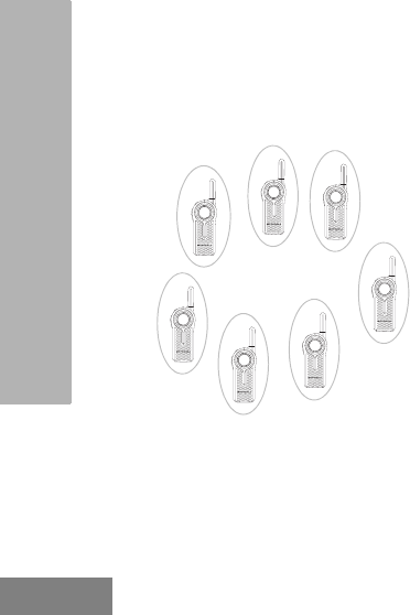
How Call All Available Works
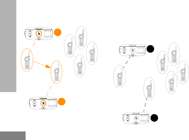
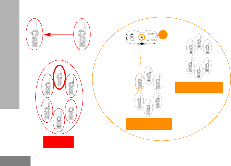
1. All users in Channel 3 and 4 are available (nobody is transmitting).
C
B
User B and C busy
in Private Call
Talking
A
Listening
Talking
CHANNEL 2
BUSY
D
CHANNEL 3
AVAILABLE
CHANNEL 4
AVAILABLE
English
67
SPECIAL RADIO CALL
FEATURES
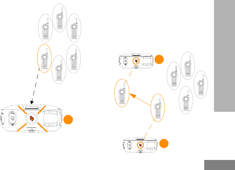
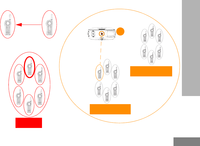
2. User D in Channel 3 initiates Call All Available by pressing the radio Top Button(*).
C
B
User B and C busy
in Private Call
Talking
A
Listening
Talking
CHANNEL 2
BUSY
D
D
“Call All Available”
CHANNEL 3
AVAILABLE
CHANNEL 4
AVAILABLE
All users in Channel 3
and 4 are AVAILABLE
(Nobody is
transmitting).
(*) Top Button must be pre-programmed to Call All Available before using this feature
English
68
SPECIAL RADIO CALL
FEATURES
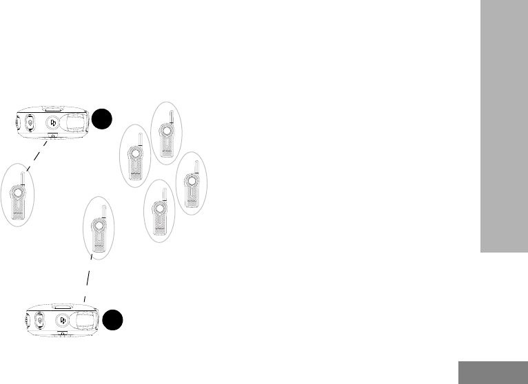
3. All users from Channel 3 and 4 are brought into a temporary “super channel” group. User D then presses the
PTT button and start talking to all available users in both channels.
C
B
User B and C busy
in Private Call
Talking
A
Listening
Talking
CHANNEL 2
BUSY
D
D
CHANNEL 3
LISTENING TO USER D
CHANNEL 4
LISTENING TO USER D
All users in Channel 3
and 4 can now listen
to user D.
English
69
SPECIAL RADIO CALL
FEATURES
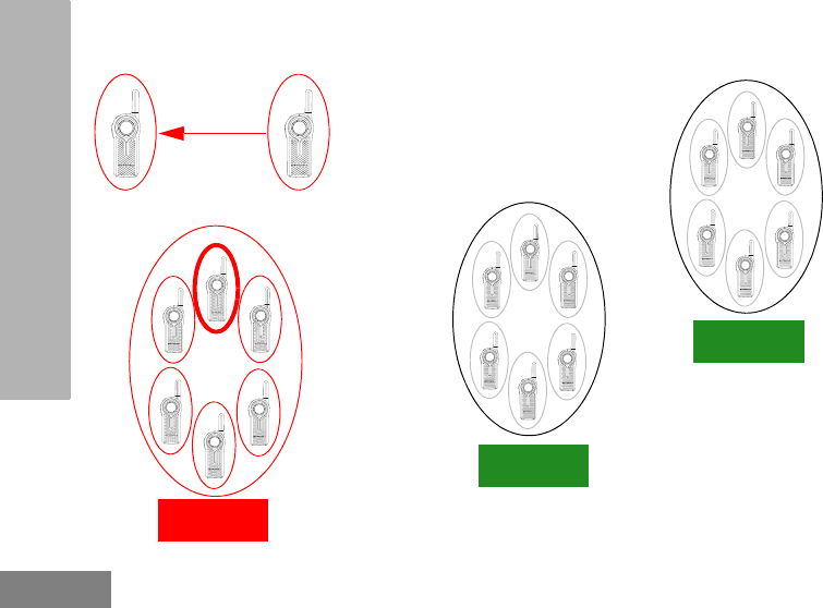
4. All radios Top Buttons in Channel 3 and 4 are solid orange indicating that Call All Available is in progress.
C
B
User B and C busy
in Private Call
Talking
A
Listening
Talking
CHANNEL 2
BUSY
D
D
User D continues talking
to all available users
CHANNEL 3
LISTENING TO USER D
CHANNEL 4
LISTENING TO USER D
English
70
SPECIAL RADIO CALL
FEATURES
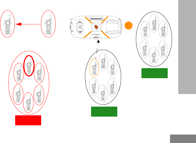
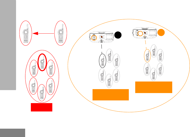
5. User D finished talking [Top Button LED indicator still solid orange(*)]. User E presses the PTT button and
starts talking to all available users. All users in Channel 3 and 4 now hear User E. All radios Top Buttons are
solid orange indicating that Call All Available is in progress.
C
B
User B and C
busy in Private
Call
Talking
A
Listening
Talking
CHANNEL 2
BUSY
D
D
CHANNEL 3
NOW LISTENING TO
USER E
CHANNEL 4
NOW LISTENING TO
USER E
E
E
(*) Users in the Call All Available group must respond back within the 4 second hang time or the Call All Available mode will be
terminated.
English
71
SPECIAL RADIO CALL
FEATURES
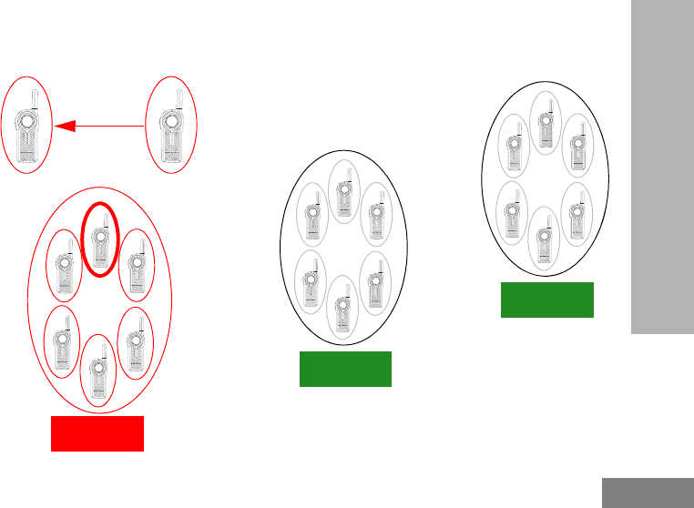
6. Once all users finished communicating (no transmissions for more than 4 seconds), the radios time out and
end the Call All Available “super channel” group. All users in channel 3 and 4 return to their original talk
channels.
C
B
User B and C busy
in Private Call
Talking
A
Listening
Talking
CHANNEL 2
BUSY
D
CHANNEL 3
AVAILABLE
CHANNEL 4
AVAILABLE
E
English
72
SPECIAL RADIO CALL
FEATURES
Call All Available Status Indicator
Note: To initiate Call All Available, press the Top Button followed by the PTT button to talk to all available users
in different channels.
Note: Top Button must be pre-programmed to Call All Available via Advanced Configuration or CPS. Call All
Available times out after 4 seconds of inactivity (no transmission detected). This table applies only to
cases in which Call All Available is programmed to the Top Button. Call All Available can also be
programmed to a radio channel. Refer to “Customer Programming Software (CPS)” on page 83 for more
information.
Table 3: Call All Available Status Indicator
Call All Available Status Top Button LED Indicator Voice Prompt or Tone
Call All Available initiated (using
Top Button press) – Initiator party Blink Orange “Call All Available”
Call All Available conversation
initiated (using the PTT button) –
Initiator party Solid Orange Standard TPT
Call All Available Call notification –
Receiver party Solid Orange Standard TPT
Call All Available conversation in
progress – Both parties Solid Orange Standard TPT
End of Call All Available – Both
parties Off None

English
73
SPECIAL RADIO CALL
FEATURES
PAGE ALL AVAILABLE
Note: This feature is useful for users with more
than 1 or 2 channels.
Page All Available allows the ability to
communicate a message to all available radio
users at once without having to change through
each channel individually. Page All Available is
a one way group voice announcement to all
users in different channels who are not
currently tied up in an ongoing radio
conversation(*).
Any user who wants to respond to a Page All
Available transmission can do so by replying
privately (by pressing the Top Button before
talking). The Page All Available feature is set
up this way to avoid all users getting tied up in
an unwanted ongoing group conversation.
Once the user transmitting in Page All
Available mode stops transmitting by releasing
the PTT button, the Page All Available mode is
terminated.
Page All Available option can be assigned
either to the Top Button or to an extra
channel(**).
(*) This feature does NOT interrupt ongoing
communications.
(**) Use CPS to assign Page All Available to a specific
channel.

English
74
SPECIAL RADIO CALL
FEATURES
Application Example 1
An employee in a retail shop uses a DLR1060
(6 channel radio) with the Top Button
programmed to Private Reply and Channel 6
programmed to Page All Available feature. This
employee is looking for anyone (in any of the
group radio channels) who can come over to
help out in the back room. The employee
changes to the Page All Available channel
before pressing the PTT button and asks “Can
someone come over to the back room to help
out?”. Whoever is available in any of the radio
channels can privately reply to the employee to
ask for more details or to confirm that they are
available to help.
Application Example 2
Anna needs to talk privately to another user
(John) and she is not sure in which channel to
find him. It is cumbersome to browse all
channels to search for John. Anna uses a
DLR1060 (6 channel radio) with the Top Button
programmed to Private Reply and Channel 6
programmed to Page All Available feature. She
switches to Channel 6 and asks “John Smith,
are you available?”
If John is available, he can reply privately (by
pressing the Top Button). If no response is
heard, it means he is busy in another radio call
or is not within the communication range.
English
75
SPECIAL RADIO CALL
FEATURES
How Page All Available works
1. All users in Channel 3 and 4 are available (nobody is transmitting).
C
B
User B and C busy
in Private Call
Talking
A
Listening
Talking
CHANNEL 2
BUSY
D
CHANNEL 3
AVAILABLE
CHANNEL 4
AVAILABLE
English
76
SPECIAL RADIO CALL
FEATURES
2. User D in Channel 3 initiates Page All Available by switching to Channel 6(*).
C
B
User B and C busy
in Private Call
Talking
A
Listening
Talking
CHANNEL 2
BUSY
D
D
“Page All Available”
CHANNEL 3
AVAILABLE
CHANNEL 4
AVAILABLE
All users in Channel 3
and 4 are AVAILABLE
(Nobody is
transmitting).
(*) Channel 6 must be pre-programmed to Page All Available before using this feature
English
77
SPECIAL RADIO CALL
FEATURES
3. All users from Channel 3 and 4 are brought into a temporary “super group”. User D then presses the PTT
button and starts talking to all available users in both channels.
C
B
User B and C busy
in Private Call
Talking
A
Listening
Talking
CHANNEL 2
BUSY
D
D
CHANNEL 3
LISTENING TO USER D
CHANNEL 4
LISTENING TO USER D
All users in Channel 3
and 4 can now listen
to user D.
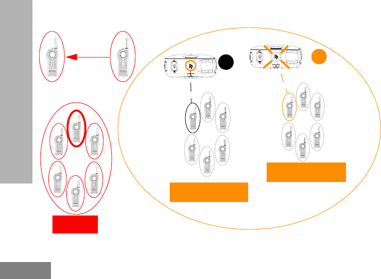
English
78
SPECIAL RADIO CALL
FEATURES
4. User D continues talking to all available users. User E wants to reply to user D and presses the
Top button(*). User E goes in queue for Private Reply.
C
B
User B and C
busy in Private
Call
Talking
A
Listening
Talking
CHANNEL 2
BUSY
D
DE
E
CHANNEL 3
LISTENING TO USER D
CHANNEL 4
LISTENING TO USER D
All users in Channel 3
and 4 are listening
user D.
“Private Reply”
(*) Top Button of Radio E must be pre-programmed to Private Reply feature
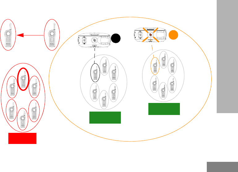
English
79
SPECIAL RADIO CALL
FEATURES
5. Once user D stops transmitting by releasing the PTT button, the Page All Available is over. All users in
Channel 3 and 4 are back to their original channel groups. User E remains in queue for Private Reply.
C
B
User B and C
busy in Private
Call
Talking
A
Listening
Talking
CHANNEL 2
BUSY
D
DE
E
CHANNEL 3
AVAILABLE
CHANNEL 4
AVAILABLE
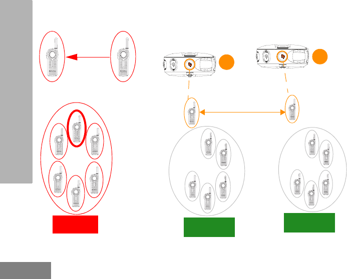
English
80
SPECIAL RADIO CALL
FEATURES
6. User E presses PTT to talk to user D. They are now engaged in a Private Conversation. Nobody else can
hear them. The Top Button LED indicator for radio D and E illuminates solid orange.
C
B
User B and C
busy in Private
Call
Talking
A
Listening
Talking
CHANNEL 2
BUSY
D
DE
E
CHANNEL 3
AVAILABLE
CHANNEL 4
AVAILABLE
Private call in progress
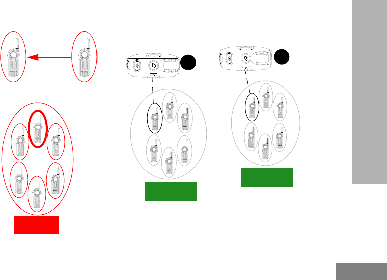
English
81
SPECIAL RADIO CALL
FEATURES
7. Once User D and E finish the private conversation, they are returned to their respective group channel. The
Top Button LED indicator both radios switched off.
C
B
User B and C
busy in Private
Call
Talking
A
Listening
Talking
CHANNEL 2
BUSY
D
DE
E
CHANNEL 3
AVAILABLE
CHANNEL 4
AVAILABLE

English
82
SPECIAL RADIO CALL
FEATURES
Page All Available Status Indicator
Note: To initiate Page All Available, press the Top Button or change to a channel that is preset to Page All
Available followed by the PTT button to talk to all available users in different channels.
Note: Top Button must be pre-programmed to Page All Available via Advanced Configuration or CPS. The only
way to respond to someone doing a Page All Available call is by Private Reply. This table applies only to
cases in which Page All Available is programmed to the Top Button. Page All Available can also be
programmed to a radio channel. Refer to “Customer Programming Software (CPS)” on page 83 for more
information.
Table 4: Page All Available Status Indicator
Page All Available Status Top Button LED Indicator Voice Prompt or Tone
Page All Available initiated (using
Top Button press) – Initiator party Blink Orange “Page All Available”
Page All Available conversation
initiated (using the PTT button) –
Initiator party Solid Orange Standard TPT
Page All Available Call notification
– Receiver party Solid Orange Standard TPT
Page All Available conversation in
progress – Both parties Solid Orange Standard TPT
End of Page All Available – Both
parties Off None
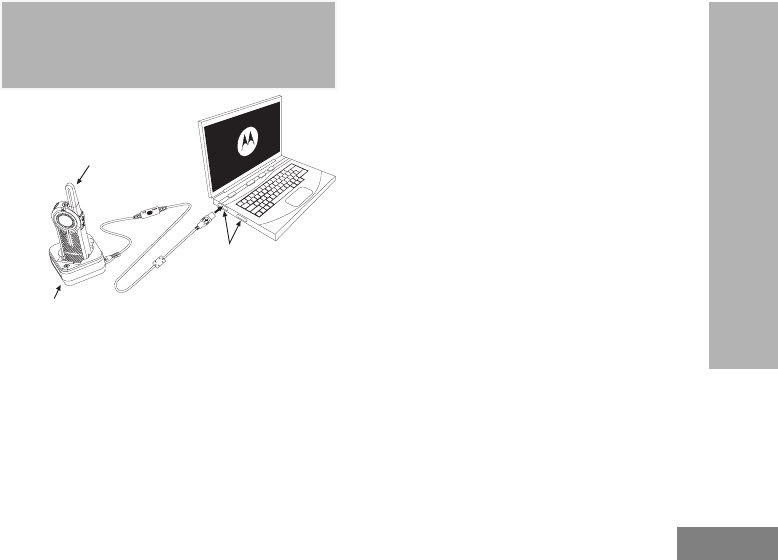
English
83
CUSTOMER PROGRAMMING
SOFTWARE (CPS)
CUSTOMER
PROGRAMMING
SOFTWARE (CPS)
Figure 1: Setting up the radio to the CPS
The easiest way to program or change features
in your radio is by using the Customer
Programming Software (CPS) and the CPS
Programming Cable(*). CPS Software is
available for free as web based downloadable
software at:
www.motorolasolutions.com/DLR
To program, connect the DLR Series radio via
the Drop-in Charger Tray and CPS
Programming Cable to your computer as
shown in the picture above. Prior to
programming, verify that the switch in the
Programming Cable is in the ‘Digital(**)’
position.
CPS allows you to easily program features
such as Direct Call, Radio Menu Options,
Private Groups, Direct Contacts, Channel
announcements, etc. It also gives you the
flexibility to prevent radio features to be
accidentally modified by users, by providing the
option to disable functionalities like Factory
Reset, Advanced Configuration Mode, etc. It
also provides security by giving the option to
set up a password for profile radio’s
management. For more information, refer to
Features Summary Chart Section at the end of
the User Guide.
Notes: (*) CPS Programming Cable P/N# is
HKKN4027_.
(**) If your CPS Programming Cable is
showing “CPS / Flash”, make sure to
position it to “Flash”.
Radio to be programmed
Drop-in Tray Charger
USB Ports
CPS Programming Cable
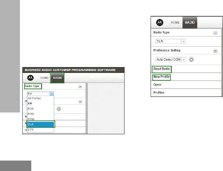
English
84
CUSTOMER PROGRAMMING
SOFTWARE (CPS)
CPS BASIC MENU INSTRUCTIONS
1. Open the CPS software and click on the
“RADIO” top tab.
2a. Click on the “READ” tab to read the radio(*), or
2b. On the drop down menu “Radio Type”, select
“DLR” if you want to open a new profile or an
existing one.
(*) You only need to select the Radio Type, if you want to open
a new or pre-determined profile. The CPS is smart enough to
determine what model it is reading.
3a. Click “Read Radio”. Radio sounds a series of
beeps to indicate reading is in progress and will
upload your radio profile settings, or
3b. Click “New Profile” to create customized profile
based on the default profile.
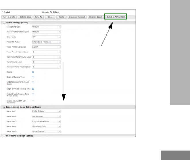
English
85
CUSTOMER PROGRAMMING
SOFTWARE (CPS)
4. Scroll down to see more feature options. Customize as necessary.
Click ONLY if you are going to
upload radios IDs for Direct Call,
Private Groups or interoperability
with DTR radios.
Scroll down for more feature options
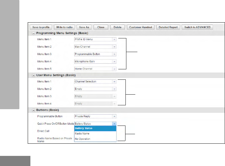
English
86
CUSTOMER PROGRAMMING
SOFTWARE (CPS)
5. You can choose which options you want to be available in the Advanced Configuration Mode. You can add
any of the features shown to be accessed by the radio Channel / Menu button in the radio basic operation
mode. You can also choose which function you want to have for ON / OFF button short press.
Programmable features to the radio basic
menu (Channel / Menu button).
Selection of options to be available
in the Advanced Configuration
mode.
Choose which function to have for ON/OFF
button short press.
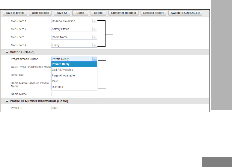
English
87
CUSTOMER PROGRAMMING
SOFTWARE (CPS)
6. You can modify the radio Top Button feature by changing the default option.
List of programmable features for
the Top Button.
Programmable features to the radio basic
menu (Channel / Menu button).
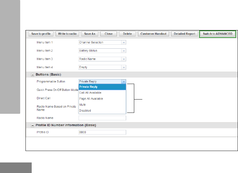
English
88
CUSTOMER PROGRAMMING
SOFTWARE (CPS)
7. In order to enable Direct Call feature in your Basic Menu options, you need to first upload the radio(s) unique
“private” identification (12 digit) number. Click on the “Switch to ADVANCED” button. Under “Privates
(Advanced)” tab, click “Add” for CPS to upload radio ID. You can customize the radio ID name under the
Name column. Once a radio ID is uploaded the CPS will give the option to enable Direct Call.
Direct Call will be listed in this drop
down menu of Top Button
programmable features once it is
enabled.
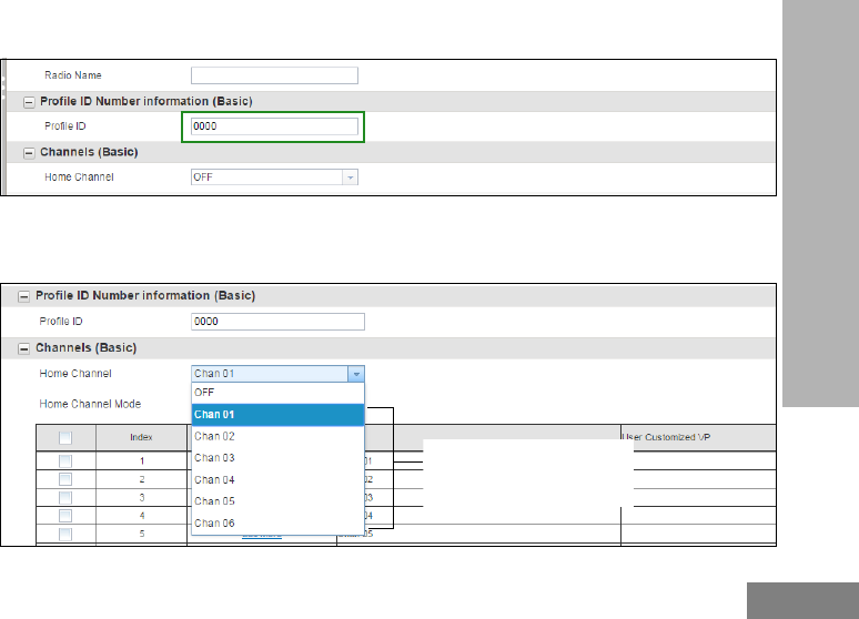
English
89
CUSTOMER PROGRAMMING
SOFTWARE (CPS)
8. Customize your PROFILE ID Number for any 4 digit number different from “0000” to differentiate your radios
in a radio fleet.
9a. Home Channel is OFF by default. If you want to assign a specific channel as your Home Channel, select the
channel using the drop down menu under “Home Channel”. CPS will enable the option to choose any
channel(*) you want as your designated Home Channel for the radio you are programming.
Select channel(*) to assign the
Home Channel to.
(*)Number of channel shown in the
drop down menu varies according to
the radio model
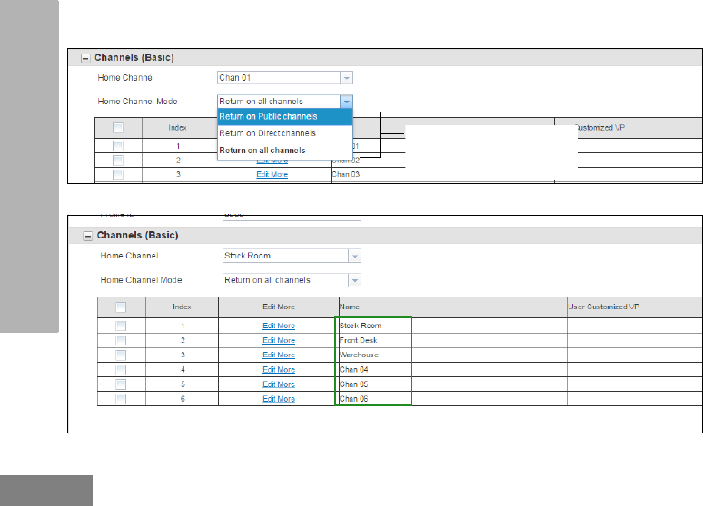
English
90
CUSTOMER PROGRAMMING
SOFTWARE (CPS)
9b. Upon setting your Home Channel, CPS will enable the option to set the Home Channel Mode. Select the
mode using the drop down menu under “Home Channel Mode”.
10. Customize the name of your channel (alias) by typing in each one of the channel boxes.
List of available modes for Home
Channel
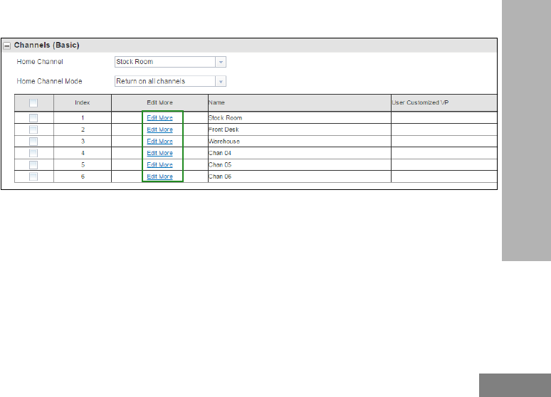
English
91
CUSTOMER PROGRAMMING
SOFTWARE (CPS)
11a. You can also set your own customized Channels Voice Prompt (VP) in order to enable your channel name to
be announced by the radio. Click on “Edit More” to edit the voice prompt.
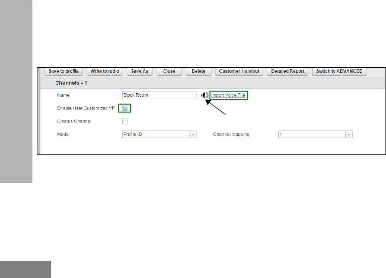
English
92
CUSTOMER PROGRAMMING
SOFTWARE (CPS)
11b. After clicking “Edit More”, you will be brought into a different menu to customize your channel name. Select
the checkbox “Enable User Customized VP” to enable the standard Voice Prompt. When there is a speaker
icon in the menu, then that channel has customized voice prompt enabled. Click on the speaker icon to
preview the User Customized VP. If you want to include your own voice recording, click on “Import Voice
File”(*).
(*) .wav audio files supported
Speaker icon indicates that customized
voice prompt is enabled for this channel
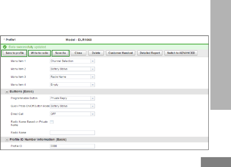
English
93
CUSTOMER PROGRAMMING
SOFTWARE (CPS)
12. Once you have changed all the settings, click “Write to radio” in order to program your radio with the new
settings. The CPS will display a window confirming the writing (programming of your radio) is successful.
You can also save your profile at any time in order to use the same settings when programming other radios
by clicking on “Save to profile”. This will save the profile to current default path in your computer. To specify
a different path to save the profile, click on the “Save As” button.
s

English
94
CUSTOMER PROGRAMMING
SOFTWARE (CPS)
Notes

English
95
CLONING
CLONING
CLONING RADIOS
You can clone DLR Series radio profiles from
one Source radio to a Target radio by using any
one of these 4 methods:
• Using a Multi Unit Charger (MUC- optional
accessory),
• Using two Single Unit Chargers (SUC) and a
Radio-to-Radio cloning cable (optional
accessory),
• the CPS (free software download), and
• Wireless PIN cloning.
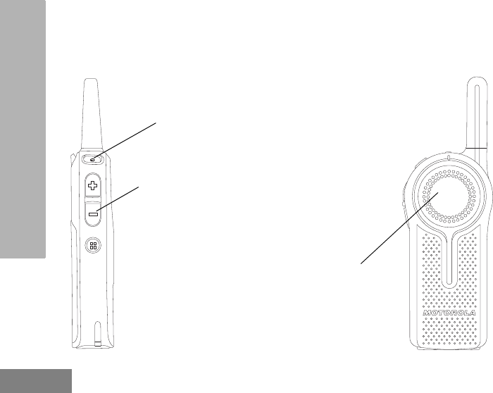
English
96
CLONING
Cloning Mode
In order to set your radios into Cloning Mode, power UP using the ON / OFF button while pressing
the PTT and (-) buttons simultaneously. Radio sounds cloning mode beeps followed by the voice
prompt “Cloning Mode, Serial”.
(-) Button
PTT (Push-To-Talk)
Button
ON / OFF Button
Power UP using the ON /
OFF button while pressing
the PTT and (-) buttons
simultaneously to enter
Cloning Mode
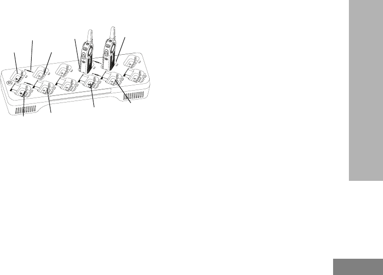
English
97
CLONING
Cloning with a Multi-Unit Charger (MUC)
(Optional Accessory)
To clone radios using the MUC, there must be
at least two radios:
• a Source radio (radio from which the profiles will
be cloned or copied) and
• a Target radio (radio to which the profiles will be
cloned from the source radio)
The Source radio has to be in Pocket 1, 4, 7 or
10 while the Target radio has to be in Pocket 2,
5, 8 or 11, matching in the MUCs pockets by
pairs as follows:
• 1 and 2,
• 4 and 5,
• 7 and 8, or
• 10 and 11.
When cloning, the MUC does not need to be
plugged into a power source, but ALL radios
require charged batteries.
1. Turn ON the Target radio and place it into one of
the MUC Target Pockets
2. Power the Source radio following the sequence
below:
• Press the PTT button and the (-) button
simultaneously while turning the radio
ON.
• Wait for 3 seconds before releasing the
buttons until the audible tone and voice
announcement “Clone Mode Serial” are
heard.
3. Place the Source radio in the source pocket that
pairs with the target pocket you chose in step 1.
Press and release the (+) button.
Pocket 1 Pocket 2
Pocket 11
Pocket 10
“CLONE” symbol Pocket 5
Pocket 8
Pocket 7
Pocket 4
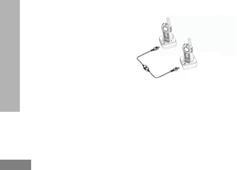
English
98
CLONING
4. After cloning is completed, the Source radio will
announce either “pass” (cloning is successful)
or “fail” (cloning has failed).
5. Once you have completed the cloning process,
turn the radios OFF and ON or, long press the
PTT button to exit the ‘cloning’ mode.
When ordering the MUC, refer to P/N#
PMLN7136_.
Notes:
• If cloning fails, refer to “What To Do If Cloning
Fails” on page 99.
• Paired Target radios and Source radios must be
of the same band type in order for the cloning to
run successfully.
• MUC pockets numbers should be read from left to
right with the Motorola logo facing front.
Cloning Radio using the Radio to Radio
(R2R) Cloning Cable (Optional Accessory)
Operating Instructions
1. Before starting the cloning process, make sure
you have:
• A Cloning Cable (P/N# HKKN4028_)
• A fully charged battery in each of the radios.
• Two Single-Unit Chargers (SUC) for cloning
DLR Series radios.
• Turn OFF the radios and,
2. Unplug any cables (power supply or USB
Note: Uses Cloning Cable
P/N# HKKN4028_

English
99
CLONING
cables) from the SUCs.
3. Plug one side of the cloning cable mini USB
connector to the first SUC and the other end to
the second SUC.
Note: During the cloning process, no power is
being applied to the SUC. The batteries will
not be charged. Only data communication is
being established between the two radios.
4. Turn ON the Target Radio and place it into one
of the SUCs.
5. For the Source Radio, power ON the radio with
the following sequence:
• Press the PTT button and the (-) button
simultaneously while turning the radio ON.
Wait 3 seconds before releasing the buttons
and you hear a distinctive audible tone saying
the word “Clone Mode Serial”.
• Place the Source Radio in its SUC. Press and
release the (+) button.
6. When the cloning is completed, the Source
Radio audible voice will announce either “pass”
(cloning is successful) or “fail” (cloning process
has failed).
7. Once the cloning process is completed, turn the
Radios OFF and ON or, long press the PTT
button to exit the ‘cloning’ mode
What To Do If Cloning Fails
The radio audible voice will announce “Fail”
indicating that the cloning process has failed. In
the event that the cloning fails, perform each of
the following steps before attempting to start
cloning process again:
1. Ensure that the batteries on both radios are fully
charged.
2. Check the cloning cable connection on both
SUCs and the cable is switched to “Cloning”.
3. Ensure that the battery is engaged properly on
the radio.

English
100
CLONING
4. Ensure that there is no debris in the charging
tray or on the radio contacts.
5. Ensure that the Target radio is turned ON.
6. Ensure that the Source radio is in cloning mode.
7. Ensure that the two radios are both from the
same type (i.e.:DLR series), same region and
have the same transmission power.
Note: This cloning cable is designed to operate
only with compatible Motorola SUC
PMLN7140_.
When ordering Cloning Cable Kit, please refer
to P/N# HKKN4028_. For more information
about the accessories, refer to “Accessories”
on page 113.
Wireless PROFILE ID Number Cloning
The PROFILE ID Number Wireless Cloning
feature is useful when you want to clone the
PROFILE ID Number for all the radios in your
fleet but you do not want to clone particular
radio settings that may be unique for each
radio (like top button configuration, Microphone
Gain, Radio Name etc) across. Wireless
PROFILE ID helps to preserve each user radio
set up but still make sure all radios are under
the same PROFILE ID Number. It is also useful
if you do not have a programming Cable,
Cloning Cable or PC easily available.
To wirelessly clone the PROFILE ID Number:
1. Power the Source radio following the sequence
below:
• Press the PTT button and the (-) button
simultaneously while turning the radio
ON.
• Wait for 3 seconds before releasing the
buttons until the audible tone and voice
announcement “Clone Mode Serial” are
heard.

English
101
CLONING
• Press and release the (-) button and the
Source Radio will announce “Wireless”.
2. Power the Target radio following the sequence
below:
• Press the PTT button and the (-) button
simultaneously while turning the radio
ON.
• Wait for 3 seconds before releasing the
buttons until the audible tone and voice
announcement “Clone Mode Serial” are
heard.
Note: Avoid putting powered ON radios (more
than 7 radios) in a container, other than the
MUC, bunched together, touching each
other.
3. On the Source radio, press and release the (+)
button to start the wireless PROFILE ID
Number cloning. The radio generates an
audible tone.
4. After cloning is completed, the Source radio will
announce either “pass” (cloning is successful)
or “fail” (cloning has failed).
5. On the Target radio, the radio receives the
PROFILE ID Number information. The Target
radio will announce either “pass” (cloning is
successful) or “fail” (cloning has failed).
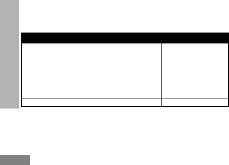
English
102
CLONING
CLONING MODE STATUS INDICATOR
To enter cloning mode, press and hold both the PTT button and (-) button at the same time, while
turning ON the radio.
Table 1: Cloning Mode Status Indicator
Cloning Mode Status LED Indicator Voice Prompt or Tone
Cloning Mode (by default is Serial) Double Blink Red “Clone Mode, Serial”
Switch to Wireless Cloning [initated
by (-) button] Double Blink Red “Wireless”
Switch to Serial Cloning [initated by
(-) button] Double Blink Red “Serial”
Clone [initiated by (+) button] –
Cloning in progress Solid Red Cloning beeps
Cloning Successful Not Available “Pass”
Cloning Fail Not Available “Fail”

English
103
TROUBLESHOOTING
TROUBLESHOOTING
Symptom Try This...
No Power
Recharge or replace the Li-Ion battery.
Extreme operating temperatures may affect battery life.
Refer to “About the Li-Ion Battery” on page 12
Unable to read the radio
(using the CPS)
Make sure that one side of the programming cable is connected to the radio
and the other side of the programming cable is connected to the USB port.
Verify that the switch on the programming cable is set at “Digital” position (or
“Flash” position in older version programming cable). Make sure the radio is
positioned correctly inside the SUC (radio making proper contact with the
charger).
Radio generates continuous
tone when PTT is pressed
Radio does not transmit when it is receiving as receive mode has higher priority
than transmit mode. Press the PTT button again when receive mode ends.
Refer to “Transmitting and Receiving” on page 27.
Radio does not transmit when
pressing the radio PTT button
The radio does not transmit if there are other users who are using the channel.
Try again after making sure nobody else is talking. By default, the PTT button is
disabled on the radio whenever there is an earpiece connected to it. Make sure
to use the earpiece in-line PTT button to transmit instead.
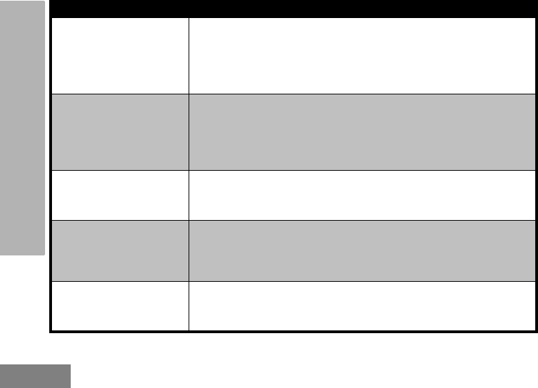
English
104
TROUBLESHOOTING
Hearing conversation from
other users that are not within
your channel
If you hear conversations from other users that don't belong to your radio fleet,
it means your radios are set up with the same Profile ID as your neighbors. Very
likely both of you have the radios in the default Profile ID Number "0000".
Customize your PROFILE ID with a 4 digit number for all your radios. Refer to
“PROFILE ID Number” on page 36 for more information.
Hearing cracking noises when
nobody is talking
Sometimes users inadvertently press the radio PTT button against objects while
wearing the radio on their belts or pockets. When they do this, the radio starts
transmitting and holding the channel therefore generating strange noises. Using
earpieces reduce the likelihood of this happening. Make sure everybody in your
team is aware of proper operation of the radios.
Audio quality not good
enough
Radio settings might not be matching up correctly. Double check to make sure
they are identical in all radios. Go into Advanced Configuration Mode and adjust
the microphone sensitivity gain (MIC Gain).
Audio sounds garbled /
robotic
Digital technology gives you the advantage to experience clear audio up to the
edge of the range. However, when maximum transmission range has been
reached, audio may sound garbled just before the transmission is lost
completely. Make sure you are within transmission range to avoid this problem.
Transmit audio is low Hold the radio vertically 1 to 2 inches from mouth when talking. For accessory,
hold the accessory microphone 2 to 3 inches from mouth when talking.
Symptom Try This...

English
105
TROUBLESHOOTING
While talking on the radio, a
loud tone interrupted the
conversation
When talking on the radio, make sure not to release the PTT button at any
moment. Whether you are using the PTT button on the radio or using an in-line
PTT in an earpiece accessory, always press the PTT button firmly until the
transmission is finished. Releasing the PTT button while transmitting and trying
to immediately to press the PTT button again causes the radio to give you a
loud denial tone.
If you press the PTT button to transmit and a busy tone is received instead of a
TPT, this means the channel is either not available, busy or there are no users
reachable within transmission range.
Limited talk range
Steel and/or concrete structures, heavy foliage, buildings or vehicles decrease
range. Check for clear line of sight to improve transmission.
Wearing radio close to body such as in a pocket or on a belt decreases range.
Change location of radio. To increase range and coverage, you can reduce
obstructions. Radios provide greater coverage in industrial and commercial
buildings.
Refer to “Transmitting and Receiving” on page 27
Symptom Try This...

English
106
TROUBLESHOOTING
Radio echo feedback
All radios produce a strong voice / audio feedback if they are too close to each
other and their volume is set too high. Lower the volume in your radio. Using
earpieces can also help reduce aduio feedback if radios are too close.
Message not transmitted or
received
Make sure the PTT button is completely pressed when transmitting.
Confirm that the radios have the same settings and PROFILE ID. Make sure
radios are in the same channel. Make sure you wait to hear for the Talk Permit
Tone before talking. Not doing this will cut out the first few words of the
transmission. Refer to “Transmitting and Receiving” on page 27 for further
information.
Recharge, replace and/or reposition batteries. Refer to “About the Li-Ion
Battery” on page 12.
Obstructions and operating indoors, or in vehicles, may interfere. Change
location. Refer to “Transmitting and Receiving” on page 27.
Heavy static or interference
Radios are too close; they must be at least five feet apart.
Radios are too far apart or obstacles are interfering with transmission.
Refer to “Transmitting and Receiving” on page 27.
Symptom Try This...

English
107
TROUBLESHOOTING
Note: Whenever a feature in the radio seems to not correspond to the default or preprogrammed values, check
to see if the radio has been programmed using the CPS with a customized profile.
For questions or comments related to this product, please contact Motorola 1-800-448-6866 or visit us at
www.motorolasolutions.com/DLR.
Low batteries
Recharge or replace Li-Ion battery.
Extreme operating temperatures affect battery life.
Refer to “About the Li-Ion Battery” on page 12.
Drop-in Charger LED light
does not blink
Check that the radio/battery is properly inserted and check the battery/charger
contacts to ensure that they are clean and charging pin is inserted correctly.
Refer to “Charging with the Drop-in Tray Single Unit Charger (SUC)” on
page 18, “DLR Series Charger LED Indicators” on page 21 and “Installing the
Lithium-Ion (Li-Ion) Battery” on page 14.
Low battery indicator is
blinking although new
batteries are inserted
Refer to “Installing the Lithium-Ion (Li-Ion) Battery” on page 14, and “About the
Li-Ion Battery” on page 12.
Battery does not charge
although it has been placed in
the drop-in charger for a while
Check drop-in tray charger is properly connected and correspond to a
compatible power supply.
Refer to “Charging with the Drop-in Tray Single Unit Charger (SUC)” on
page 18 and “Charging A Stand-Alone Battery” on page 18.
Check the charger’s LEDs indicators to see if the battery has a problem. Refer
to “DLR Series Charger LED Indicators” on page 21.
Symptom Try This...