Motorola Solutions 89FT5876 2-Way Portable Radio (with Bluetooth and Bluetooth LE) User Manual MTP3500 Feature User Guide
Motorola Solutions, Inc. 2-Way Portable Radio (with Bluetooth and Bluetooth LE) MTP3500 Feature User Guide
Contents
- 1. Manual
- 2. RF Safety Manual
Manual

MTP3500 Feature User
Guide
Mobile Release 17.0
*MN001488A01*
MN001488A01-BF (en-US)
OCTOBER 2018
© 2018 Motorola Solutions, Inc. All rights reserved
DRAFT
Contents
List of Figures............................................................................................................12
List of Tables............................................................................................................. 13
Declaration of Conformity........................................................................................ 14
Safety Information.....................................................................................................15
Notice to Users (FCC and Industry Canada)...........................................................16
Copyrights................................................................................................................. 17
General Information.................................................................................................. 18
1.1 Icon Conventions................................................................................................................... 18
1.2 Using this Guide.................................................................................................................... 18
1.3 Feature and Service Availability............................................................................................ 18
Getting Started.......................................................................................................... 19
2.1 Product Technical Information............................................................................................... 19
2.2 Before Power On................................................................................................................... 20
2.2.1 Attaching the Antenna..............................................................................................20
2.2.2 Inserting the SIM Card............................................................................................. 21
2.2.3 Installing the Battery................................................................................................ 22
2.2.4 Removing the Battery.............................................................................................. 22
2.2.5 Charging the Battery................................................................................................ 22
2.2.6 Battery Charging Indications....................................................................................23
2.2.7 Low Battery Indication..............................................................................................23
2.3 Controls and Indicators..........................................................................................................23
2.4 Display................................................................................................................................... 26
2.4.1 Configurable Idle Screen......................................................................................... 27
2.5 Status Icons........................................................................................................................... 28
2.6 Powering On the Radio..........................................................................................................31
2.7 PIN Code Authentication....................................................................................................... 31
2.7.1 Unlocking Your Radio.............................................................................................. 32
2.7.2 Unblocking Your Radio............................................................................................ 32
2.8 Locking or Unlocking the Keys or Buttons............................................................................. 32
2.9 Holding Your Radio................................................................................................................32
2.10 High or Low Audio Toggle................................................................................................... 33
2.10.1 Using High Audio................................................................................................... 33
2.10.2 Using Low Audio.................................................................................................... 33
2.11 During a Call........................................................................................................................ 34
2.12 Entering TMO or DMO Mode...............................................................................................34
MN001488A01-BF (en-US)
Contents
2
DRAFT
2.13 Selecting Talkgroups........................................................................................................... 34
2.13.1 Talkgroup Icons Selection......................................................................................34
2.14 One-Touch Buttons..............................................................................................................36
Modes.........................................................................................................................39
3.1 Trunked Mode Operation.......................................................................................................39
3.1.1 Entering TMO Mode.................................................................................................39
3.1.2 Making Group Calls in TMO.....................................................................................39
3.1.3 Receiving Group Calls in Idle...................................................................................40
3.1.4 Receiving Group Calls during Ongoing Group Calls................................................40
3.1.5 Dynamic Group Number Assignment (DGNA).........................................................40
3.1.5.1 DGNA Reception........................................................................................40
3.1.5.2 DGNA Auto Select Group.......................................................................... 41
3.1.5.3 DGNA Auto Reselect Group...................................................................... 41
3.1.5.4 Viewing DGNA Talkgroups........................................................................ 41
3.1.6 Broadcast Call..........................................................................................................41
3.1.6.1 Broadcast Calls Initiated by Users............................................................. 41
3.1.6.2 Initializing Broadcast Calls......................................................................... 41
3.1.7 Phone and Private Automatic Branch Exchange (PABX) Calls............................... 42
3.1.8 Assistance Call........................................................................................................ 42
3.1.9 Call Modification.......................................................................................................42
3.2 Local Site Trunking................................................................................................................ 42
3.2.1 Entering Local Site Trunking....................................................................................43
3.2.2 Exiting Local Site Trunking...................................................................................... 43
3.3 Direct Mode Operation...........................................................................................................44
3.3.1 Entering DMO Mode................................................................................................ 44
3.3.2 Making Group Calls in DMO.................................................................................... 44
3.3.3 Receiving Group Calls in Idle...................................................................................44
3.3.4 Selecting DMO Communications Options................................................................45
3.3.5 DMO Private Priority Call......................................................................................... 45
3.3.6 Talkgroup for Individual Calls...................................................................................45
3.3.7 Network Monitor.......................................................................................................46
3.3.7.1 Enabling Network Monitor.......................................................................... 46
3.3.8 Communication through Repeaters......................................................................... 47
3.3.9 Communication through Gateways..........................................................................47
3.3.10 Gateway and Repeater Synchronization............................................................... 48
3.4 Transmit Inhibit Mode............................................................................................................ 48
3.5 Emergency Operations.......................................................................................................... 49
3.5.1 Emergency Alarm.................................................................................................... 49
3.5.2 Emergency Group Call.............................................................................................50
MN001488A01-BF (en-US)
Contents
3
DRAFT
3.5.2.1 Making Emergency Group Calls................................................................ 50
3.5.2.2 Receiving Emergency Group Calls............................................................ 50
3.5.3 Non-Tactical Emergency..........................................................................................51
3.5.4 Emergency Individual Calls (Private or MSISDN)....................................................51
3.5.5 Emergency SDS Status........................................................................................... 51
3.5.6 Emergency Hot Microphone.................................................................................... 51
3.5.7 Alternating Hot Microphone..................................................................................... 51
3.5.8 Silent Emergency Mode...........................................................................................52
3.5.9 Invisible Emergency.................................................................................................52
3.5.10 Emergency Alert.................................................................................................... 53
3.5.11 Disaster Alert......................................................................................................... 53
3.5.11.1 Initializing Disaster Alert Calls..................................................................54
3.5.12 Exiting Emergency Operations.............................................................................. 54
3.6 Repeater Mode...................................................................................................................... 54
Main Menu..................................................................................................................56
4.1 Scrolling through the Menu....................................................................................................56
4.2 Menu Icons............................................................................................................................ 56
4.3 Messages.............................................................................................................................. 57
4.3.1 New Message.......................................................................................................... 57
4.3.1.1 Sending Messages to Private/Phone......................................................... 58
4.3.1.2 Sending Messages to Groups....................................................................58
4.3.1.3 Sending Store and Forward Messages......................................................58
4.3.1.4 Delivery Report.......................................................................................... 59
4.3.2 Inbox........................................................................................................................ 60
4.3.2.1 Entering the Inbox...................................................................................... 61
4.3.2.2 Receiving New Messages..........................................................................61
4.3.2.3 Using Submenus in the Inbox and the Outbox...........................................61
4.3.2.4 Embedded Number.................................................................................... 62
4.3.2.5 Storing Numbers from Messages...............................................................62
4.3.2.6 Calling Numbers in Messages................................................................... 62
4.3.2.7 Making Group Calls on the Talkgroup of the Message Sender................. 63
4.3.2.8 Immediate Message...................................................................................63
4.3.3 Outbox..................................................................................................................... 63
4.3.4 Call-Out (CO) Box....................................................................................................64
4.3.4.1 Call-Out Icons............................................................................................ 64
4.3.5 Wireless Application Protocol (WAP) Box................................................................64
4.3.6 Templates................................................................................................................ 64
4.3.6.1 Sending User-Defined Templates.............................................................. 64
4.3.6.2 Managing User-Defined Templates........................................................... 65
MN001488A01-BF (en-US)
Contents
4
DRAFT
4.3.7 Predefined Templates..............................................................................................65
4.3.7.1 Viewing Predefined Templates.................................................................. 65
4.3.7.2 Sending Predefined Templates..................................................................65
4.3.8 Status Messages..................................................................................................... 66
4.3.8.1 Viewing a Status Message Number........................................................... 66
4.3.8.2 Sending Status Messages......................................................................... 66
4.3.8.3 Targeted Status Messages........................................................................ 66
4.3.9 Sending an RMS Status...........................................................................................67
4.3.10 Additional Address................................................................................................. 67
4.3.10.1 Enabling or Disabling Additional Address................................................ 67
4.3.10.2 Selecting Additional Address................................................................... 68
4.3.10.3 Viewing Additional Address......................................................................68
4.3.10.4 Entering New Additional Address.............................................................68
4.3.10.5 Editing Additional Address....................................................................... 68
4.3.10.6 Deleting Additional Address..................................................................... 69
4.3.11 Call-Out Availability................................................................................................69
4.3.11.1 Setting Call-Out Availability......................................................................69
4.4 Contacts.................................................................................................................................69
4.4.1 Creating Contacts.................................................................................................... 70
4.4.2 Editing Contacts.......................................................................................................71
4.4.3 Deleting Numbers.................................................................................................... 71
4.4.4 Deleting Contacts.....................................................................................................71
4.4.5 Checking Capacity................................................................................................... 72
4.4.6 Dialing through the Contact List...............................................................................72
4.5 Bluetooth................................................................................................................................72
4.5.1 Bluetooth Settings....................................................................................................72
4.5.1.1 Configuring Bluetooth Settings...................................................................72
4.5.2 Enabling and Disabling Bluetooth............................................................................ 73
4.5.3 Pairing Bluetooth Devices with Your Radio............................................................. 73
4.5.4 Devices.................................................................................................................... 74
4.5.4.1 Connecting or Disconnecting Devices....................................................... 74
4.5.4.2 Managing Devices......................................................................................74
4.5.5 Disconnecting All Devices........................................................................................75
4.5.6 Setting Indoor Location............................................................................................ 75
4.5.6.1 Viewing Detected Beacon.......................................................................... 75
4.5.7 Connecting Firearms Devices..................................................................................76
4.6 Browser..................................................................................................................................76
4.7 Man Down..............................................................................................................................76
4.7.1 Setting Man Down....................................................................................................77
MN001488A01-BF (en-US)
Contents
5
DRAFT
4.8 Security..................................................................................................................................77
4.8.1 PIN Protect...............................................................................................................77
4.8.1.1 Protecting the Radio with a PIN Code........................................................77
4.8.1.2 Changing PIN Codes................................................................................. 77
4.8.2 Setting Keypad Lock................................................................................................ 78
4.8.2.1 Keypad Lock Notification............................................................................78
4.8.2.2 Setting Automatic Keylock Delay............................................................... 78
4.8.2.3 Setting Keylock on Startup.........................................................................78
4.8.3 Air Encryption...........................................................................................................78
4.8.3.1 Viewing Air Encryption State......................................................................79
4.8.3.2 Deleting User Keys.................................................................................... 79
4.8.4 K Validity.................................................................................................................. 79
4.8.4.1 Verifying K Validity..................................................................................... 79
4.8.5 SCK (Air Interface Encryption Class 2)....................................................................80
4.8.5.1 TMO SCK...................................................................................................80
4.8.5.2 DMO SCK.................................................................................................. 80
4.8.5.3 Changing DMO SCK.................................................................................. 81
4.8.6 Covert Mode............................................................................................................ 81
4.8.6.1 Activating Covert Mode.............................................................................. 81
4.8.6.2 Setting Vibrate in Covert Mode.................................................................. 82
4.8.7 Remote Control........................................................................................................82
4.8.7.1 Status Remote Control...............................................................................82
4.8.7.2 SDS Remote Control..................................................................................83
4.8.7.3 Setting Remote Control..............................................................................83
4.9 Setup..................................................................................................................................... 83
4.9.1 Vibrate......................................................................................................................83
4.9.1.1 Setting Default Vibrate............................................................................... 83
4.9.1.2 Setting Detail Vibrate................................................................................. 84
4.9.2 Ring Style.................................................................................................................84
4.9.2.1 Setting Ring Style.......................................................................................84
4.9.3 Set Volume.............................................................................................................. 84
4.9.3.1 Setting Volume...........................................................................................85
4.9.4 Language................................................................................................................. 85
4.9.4.1 Setting Language....................................................................................... 85
4.9.5 Data Setup............................................................................................................... 85
4.9.5.1 Setting Data Function.................................................................................86
4.9.6 Audio........................................................................................................................86
4.9.6.1 Audio Profiles............................................................................................. 86
4.9.6.2 Howling Suppression................................................................................. 86
MN001488A01-BF (en-US)
Contents
6
DRAFT
4.9.6.3 Audio Toggle.............................................................................................. 87
4.9.6.4 Volume Adjustment Mode.......................................................................... 87
4.9.7 Tones....................................................................................................................... 88
4.9.7.1 Keypad Tone..............................................................................................88
4.9.7.2 All Tones.................................................................................................... 88
4.9.7.3 Talk Permit................................................................................................. 88
4.9.7.4 Clear to Send............................................................................................. 89
4.9.7.5 Periodic Alert..............................................................................................89
4.9.7.6 D-PTT Tones..............................................................................................89
4.9.8 Display..................................................................................................................... 90
4.9.8.1 Setting Flip Display.................................................................................... 90
4.9.8.2 Setting Font Level...................................................................................... 90
4.9.8.3 Setting Large Idle Font...............................................................................91
4.9.8.4 Setting Screen Saver................................................................................. 91
4.9.8.5 Setting Backlight........................................................................................ 91
4.9.8.6 Setting Brightness...................................................................................... 92
4.9.8.7 Setting LCD Off.......................................................................................... 92
4.9.8.8 Setting Wallpaper.......................................................................................92
4.9.9 Time and Date......................................................................................................... 92
4.9.9.1 Setting the Time Format.............................................................................93
4.9.9.2 Setting the Time Manually..........................................................................93
4.9.9.3 Setting the Date Format............................................................................. 93
4.9.9.4 Setting the Date Manually.......................................................................... 93
4.9.9.5 Setting Time Offset.................................................................................... 94
4.9.9.6 Setting Automatic Updates for the Time and Date ....................................94
4.9.10 Energy Economy....................................................................................................94
4.9.10.1 Enabling or Disabling Energy Economy...................................................94
4.9.10.2 Viewing the Energy Economy Status....................................................... 94
4.9.11 Transmission Power Class.................................................................................... 95
4.9.11.1 Selecting RF Power................................................................................. 95
4.9.12 Accessory (Accry) Setup........................................................................................95
4.9.12.1 Selecting CORE/Other/Secondary Accessories...................................... 95
4.9.13 Book On................................................................................................................. 96
4.9.14 Rotary Knob........................................................................................................... 96
4.9.14.1 Setting Rotary Lock..................................................................................96
4.9.14.2 Setting In Keypad Lock............................................................................ 96
4.9.14.3 Setting Rotary Knob Wrap Around...........................................................97
4.9.14.4 Setting Rotary Knob Scroll Range........................................................... 97
4.9.14.5 Setting Rotary Knob Talkgroup Selection................................................ 97
MN001488A01-BF (en-US)
Contents
7
DRAFT
4.9.14.6 Setting Rotary Knob Function Keys......................................................... 97
4.9.15 Default Setting....................................................................................................... 98
4.9.15.1 Selecting Default Setting..........................................................................98
4.10 Group Setup........................................................................................................................ 98
4.10.1 Setting Operations Parameters..............................................................................98
4.10.1.1 Standard Home Group............................................................................. 99
4.10.2 Scan.......................................................................................................................99
4.10.2.1 Activating Talkgroup Scanning.................................................................99
4.10.2.2 Setting Talkgroups in the Active Scan List...............................................99
4.10.2.3 Setting Scan Lists.................................................................................. 100
4.10.2.4 Deleting Talkgroups from Scan Lists..................................................... 100
4.10.3 My Groups........................................................................................................... 100
4.10.3.1 Adding Favorite Folders......................................................................... 100
4.10.3.2 Adding Talkgroups to Favorite Folders.................................................. 100
4.10.3.3 Deleting Favorite Folders....................................................................... 101
4.10.3.4 Deleting Talkgroup from Favorite Folders..............................................101
4.11 Individual Setup................................................................................................................. 101
4.11.1 Trunked Mode......................................................................................................101
4.11.1.1 Enabling or Disabling Call Waiting......................................................... 101
4.11.1.2 Setting Call Forwarding..........................................................................102
4.12 Favorites............................................................................................................................ 102
4.12.1 Adding Folders to Favorites................................................................................. 102
4.12.2 Adding Contact Numbers to Favorites................................................................. 102
4.12.3 Making Private Calls to Favorite Contact Numbers............................................. 103
4.12.4 Adding Talkgroups to Favorites........................................................................... 103
4.12.5 Managing Folders in Favorites.............................................................................103
4.12.6 Deleting Folders in Favorites............................................................................... 104
4.12.7 Deleting Items from Favorites Folder...................................................................104
4.12.8 Deleting All Items from Favorite Folders..............................................................104
4.13 My Info............................................................................................................................... 105
4.13.1 Viewing Personal Information.............................................................................. 105
4.14 Recent Calls...................................................................................................................... 105
4.14.1 Viewing Recent Calls........................................................................................... 105
4.14.2 Calling from Recent Calls.................................................................................... 106
4.14.3 Storing Recent Calls to Contacts......................................................................... 106
4.14.4 Deleting Recent Calls.......................................................................................... 107
4.15 Networks............................................................................................................................107
4.15.1 Selecting Network Operation Mode..................................................................... 107
4.15.2 Network Select.....................................................................................................108
MN001488A01-BF (en-US)
Contents
8
DRAFT
4.15.2.1 Selecting Your Network..........................................................................108
4.15.2.2 Using Select Net Registration................................................................ 108
4.15.3 Talkgroup Network Select....................................................................................108
4.15.3.1 Selecting Your Talkgroup Network.........................................................108
4.15.3.2 Using Select TG Net Registration.......................................................... 108
4.15.3.3 Using Prefer TG Net Registration.......................................................... 109
4.15.3.4 Using Any TG Net Registration.............................................................. 109
4.16 Location............................................................................................................................. 109
4.16.1 Enabling GNSS....................................................................................................109
4.16.2 Viewing Your Position.......................................................................................... 110
4.16.3 Viewing Testpage................................................................................................ 110
4.16.4 Changing GNSS Accuracy...................................................................................110
4.16.5 Backlog................................................................................................................ 111
4.16.5.1 Enabling or Disabling Backlog............................................................... 111
4.16.5.2 Viewing Backlog Reports....................................................................... 111
4.16.5.3 Deleting All Backlog Reports..................................................................111
4.17 Packet Data....................................................................................................................... 111
4.17.1 Viewing Data Statistics........................................................................................ 112
4.17.2 Viewing Encryption Status................................................................................... 112
4.18 Crypto Menu...................................................................................................................... 112
4.18.1 Enabling or Disabling SIM Card End-to-End Encryption......................................112
4.18.2 Setting Clear Call Alarm.......................................................................................113
4.18.3 Updating Encryption Keys....................................................................................113
4.18.4 Viewing OPTA......................................................................................................114
4.18.5 Setting OPTA Filter.............................................................................................. 114
4.18.6 Starting Crypto Registration.................................................................................114
4.18.7 Configuring Audio Settings.................................................................................. 114
4.18.8 Setting DMO Encryption Mode............................................................................ 114
4.18.9 Setting Encryption Keys for SDS Messages........................................................115
Features................................................................................................................... 116
5.1 Ambience Listening (AL) Call.............................................................................................. 116
5.2 Bluetooth..............................................................................................................................116
5.2.1 Bluetooth Interactions............................................................................................ 117
5.2.2 Discoverable Mode................................................................................................ 117
5.2.3 Add Bluetooth Devices...........................................................................................117
5.2.4 Bluetooth Smart Proximity Pairing......................................................................... 117
5.2.5 Bluetooth Sensor Data...........................................................................................118
5.3 Buffer Full Overwrite Policy................................................................................................. 118
5.4 Call-Out................................................................................................................................118
MN001488A01-BF (en-US)
Contents
9
DRAFT
5.4.1 Types of Call-Out Alerts.........................................................................................119
5.4.2 Call-Out Modes Interaction.................................................................................... 120
5.4.3 Call-Out Service Phases........................................................................................120
5.5 Collaborative Messaging..................................................................................................... 121
5.6 Dialing through Soft Numeric Keypad..................................................................................121
5.7 Global Navigation Satellite System (GNSS) Location Service............................................ 121
5.7.1 Enhance GNSS Performance................................................................................ 122
5.7.2 Location Report Backlog........................................................................................123
5.7.3 GNSS Icon............................................................................................................. 123
5.7.4 Different Location Displays.................................................................................... 123
5.7.5 GNSS Accuracy..................................................................................................... 124
5.8 Home Display Text Message...............................................................................................124
5.9 MS-ISDN..............................................................................................................................124
5.10 Private Call........................................................................................................................ 124
5.10.1 Making Private Calls............................................................................................ 125
5.11 Phone and Private Automatic Branch Exchange (PABX) Calls.........................................125
5.11.1 Making Phone or PABX Calls.............................................................................. 125
5.12 Phone/PABX Speed Dial................................................................................................... 125
5.12.1 Using the Phone/PABX Speed Dial..................................................................... 126
5.13 Radio Messaging System (RMS).......................................................................................126
5.13.1 RMS Icons........................................................................................................... 126
5.14 Radio User Assignment (RUA) and Radio User Identity (RUI)..........................................127
5.15 SIM Card End-to-End Encryption...................................................................................... 127
5.16 Short Number Dial............................................................................................................. 128
5.17 Talkgroup Dialing by Index................................................................................................ 128
5.18 Terminal Permanent Disable............................................................................................. 129
5.19 Terminal Temporary Disable or Enable............................................................................. 129
5.20 Writing Text........................................................................................................................129
5.20.1 Text Entry Icons................................................................................................... 129
5.20.2 Keys Usage..........................................................................................................130
5.21 Wireless Application Protocol (WAP).................................................................................130
5.21.1 WAP Browser.......................................................................................................130
5.21.2 Entering the Browser........................................................................................... 131
5.21.3 Entering Browser Menu Panes............................................................................ 131
5.21.4 Tips for Browsing................................................................................................. 131
5.21.4.1 Creating Bookmarks through the Navigate Pane...................................131
5.21.4.2 Creating Bookmarks through the Bookmarks Pane............................... 131
5.21.4.3 Using Bookmarks................................................................................... 132
5.21.4.4 Saving Pages......................................................................................... 132
MN001488A01-BF (en-US)
Contents
10
DRAFT
5.21.4.5 Selecting Saved Pages.......................................................................... 132
5.21.5 Disabled Packet Data Service............................................................................. 132
5.21.6 Disabled Browser Entry....................................................................................... 133
5.21.7 Browser Keys Usage........................................................................................... 133
5.21.8 Browser Menu Panes Overview...........................................................................134
5.21.9 Navigate Pane..................................................................................................... 134
5.21.10 Advanced........................................................................................................... 135
5.21.11 Bookmarks Pane................................................................................................135
5.21.11.1 Working with the Options Pane for Selected Bookmarks.....................135
5.21.11.2 Working with the Saved Pages Folder................................................. 136
5.21.12 History Pane...................................................................................................... 136
5.21.12.1 Navigating to Recently Visited URLs................................................... 136
5.21.13 Tools Pane.........................................................................................................137
5.21.14 Options Pane..................................................................................................... 137
5.21.15 Text Input Pane..................................................................................................137
5.21.16 WAP Push..........................................................................................................138
5.21.16.1 New WAP Messages........................................................................... 138
5.21.16.2 Viewing WAP Messages...................................................................... 138
Appendix A: Tones..................................................................................................139
Appendix B: LED Indications.................................................................................141
Appendix C: Troubleshooting................................................................................142
Appendix D: Maintenance...................................................................................... 145
D.1 Storage................................................................................................................................145
D.2 Extending Battery Life......................................................................................................... 145
D.3 Battery Charging Temperature............................................................................................145
D.4 Additional Battery Warnings/Cautions.................................................................................145
D.5 Looking after Your Radio.................................................................................................... 146
MN001488A01-BF (en-US)
Contents
11
DRAFT
List of Figures
Figure 1: Charger Mode Screen............................................................................................................. 23
Figure 2: Default Home Screen with Icons............................................................................................. 26
Figure 3: Trunked Mode Operation........................................................................................................ 39
Figure 4: Direct Mode Operation............................................................................................................ 44
Figure 5: Communication through Repeaters.........................................................................................47
Figure 6: Communication through Gateways......................................................................................... 47
Figure 7: Repeater Mode Operation.......................................................................................................55
Figure 8: Call-Out Message..................................................................................................................119
MN001488A01-BF (en-US)
List of Figures
12
DRAFT
List of Tables
Table 1: Special Notations......................................................................................................................18
Table 2: Product Technical Information..................................................................................................19
Table 3: Battery Icons.............................................................................................................................23
Table 4: Controls and Indicators.............................................................................................................24
Table 5: Display......................................................................................................................................26
Table 6: Colors of the Soft Key Area...................................................................................................... 27
Table 7: Status Icons..............................................................................................................................28
Table 8: During the Call..........................................................................................................................34
Table 9: Talkgroup Icons........................................................................................................................ 35
Table 10: One-Touch Button Features .................................................................................................. 36
Table 11: Emergency Operation Dependencies.....................................................................................53
Table 12: Menu Icons............................................................................................................................. 56
Table 13: Inbox Icons............................................................................................................................. 60
Table 14: Outbox Icons.......................................................................................................................... 63
Table 15: Call-Out Icons.........................................................................................................................64
Table 16: Contact Types........................................................................................................................ 70
Table 17: Different Location Displays...................................................................................................123
Table 18: RMS Icons............................................................................................................................ 126
Table 19: Radios Interactions...............................................................................................................128
Table 20: Text Entry Screen Icons....................................................................................................... 129
Table 21: Keys Usage.......................................................................................................................... 130
Table 22: Browser Keys Interactions....................................................................................................133
Table 23: Browser Menu Panes........................................................................................................... 134
Table 24: Additional Menu Panes.........................................................................................................134
Table 25: Browser Text Input Icons......................................................................................................137
Table 26: Radio Tones......................................................................................................................... 139
Table 27: LED Status Indications......................................................................................................... 141
Table 28: Battery Charging LED Indications........................................................................................ 141
Table 29: Displayed Messages............................................................................................................ 142
MN001488A01-BF (en-US)
List of Tables
13
DRAFT

Declaration of Conformity
This declaration is applicable to your radio only if your radio is labeled with the FCC logo shown below.
Declaration of Conformity
Per FCC CFR 47 Part 2 Section 2.1077(a)
Responsible Party
Name: Motorola Solutions, Inc.
Address: 1303 East Algonquin Road, Schaumburg, IL 60196-1078, U.S.A.
Phone Number: 1-800-927-2744
Hereby declares that the product:
Model Name: MTP3500
conforms to the following regulations:
FCC Part 15, subpart B, section 15.107(a), 15.107(d), and section 15.109(a)
Class B Digital Device
As a personal computer peripheral, this device complies with Part 15 of the FCC Rules. This device
complies with Industry Canada license-exempt RSS standard(s). Operation is subject to the follow-
ing two conditions:
1This device may not cause harmful interference, and
2This device must accept any interference received, including interference that may cause unde-
sired operation.
NOTICE: This equipment has been tested and found to comply with the limits for a Class
B digital device, pursuant to part 15 of the FCC Rules and Industry Canada license-ex-
empt RSS standard. These limits are designed to provide reasonable protection against
harmful interference in a residential installation. This equipment generates, uses and can
radiate radio frequency energy and, if not installed and used in accordance with the in-
structions, may cause harmful interference to radio communications. However, there is
no guarantee that interference will not occur in a particular installation.
If this equipment does cause harmful interference to radio or television reception, which
can be determined by turning the equipment off and on, the user is encouraged to try to
correct the interference by one or more of the following measures:
• Reorient or relocate the receiving antenna.
• Increase the separation between the equipment and receiver.
• Connect the equipment into an outlet on a circuit different from that to which the re-
ceiver is connected.
• Consult the dealer or an experienced radio or TV technician for help.
MN001488A01-BF (en-US)
Declaration of Conformity
14
DRAFT
Safety Information
RF Energy Exposure and Product Safety Guide for Portable Two-Way Radios
ATTENTION!
This radio is restricted to Occupational use only. Before using the radio, read the RF Energy
Exposure and Product Safety Guide for Portable Two-Way Radios which contains important operating
instructions for safe usage and RF energy awareness and control for Compliance with applicable
standards and Regulations.
For a list of Motorola Solutions-approved antennas, batteries, and other accessories, visit the following
website:
http://www.motorolasolutions.com
Under Industry Canada regulations, this radio transmitter may only operate using an antenna of a type
and maximum (or lesser) gain approved for the transmitter by Industry Canada. To reduce potential
radio interference to other users, the antenna type and its gain should be so chosen that the equivalent
isotropically radiated power (e.i.r.p.) is not more than that necessary for successful communication.
This radio transmitter has been approved by Industry Canada to operate with Motorola Solutions-
approved antenna with the maximum permissible gain and required antenna impedance for each
antenna type indicated. Antenna types not included in this list, having a gain greater than the maximum
gain indicated for that type, are strictly prohibited for use with this device.
MN001488A01-BF (en-US)
Safety Information
15
DRAFT
Notice to Users (FCC and Industry
Canada)
This device complies with Part 15 of the FCC rules and Industry Canada's license-exempt RSS's per
the following conditions:
•This device may not cause harmful interference.
• This device must accept any interference received, including interference that may cause undesired
operation.
• Changes or modifications made to this device, not expressly approved by Motorola Solutions, could
void the authority of the user to operate this equipment.
MN001488A01-BF (en-US)
Notice to Users (FCC and Industry Canada)
16
DRAFT

Copyrights
The Motorola Solutions products described in this document may include copyrighted Motorola
Solutions computer programs. Laws in the United States and other countries preserve for Motorola
Solutions certain exclusive rights for copyrighted computer programs. Accordingly, any copyrighted
Motorola Solutions computer programs contained in the Motorola Solutions products described in this
document may not be copied or reproduced in any manner without the express written permission of
Motorola Solutions.
© 2018 Motorola Solutions, Inc. All Rights Reserved
No part of this document may be reproduced, transmitted, stored in a retrieval system, or translated
into any language or computer language, in any form or by any means, without the prior written
permission of Motorola Solutions, Inc.
Furthermore, the purchase of Motorola Solutions products shall not be deemed to grant either directly
or by implication, estoppel or otherwise, any license under the copyrights, patents or patent
applications of Motorola Solutions, except for the normal non-exclusive, royalty-free license to use that
arises by operation of law in the sale of a product.
Disclaimer
Please note that certain features, facilities, and capabilities described in this document may not be
applicable to or licensed for use on a specific system, or may be dependent upon the characteristics of
a specific subscriber unit or configuration of certain parameters. Please refer to your Motorola
Solutions contact for further information.
Trademarks
MOTOROLA, MOTO, MOTOROLA SOLUTIONS, and the Stylized M Logo are trademarks or
registered trademarks of Motorola Trademark Holdings, LLC and are used under license. All other
trademarks are the property of their respective owners.
European Union (EU) Waste of Electrical and Electronic Equipment (WEEE)
directive
The European Union's WEEE directive requires that products sold into EU countries must have
the crossed out trash bin label on the product (or the package in some cases).
As defined by the WEEE directive, this cross-out trash bin label means that customers and end-users
in EU countries should not dispose of electronic and electrical equipment or accessories in household
waste.
Customers or end-users in EU countries should contact their local equipment supplier representative or
service centre for information about the waste collection system in their country.
MN001488A01-BF (en-US)
Copyrights
17
DRAFT
General Information
1.1
Icon Conventions
The documentation set is designed to give the reader more visual clues. The following graphic icons
are used throughout the documentation set.
DANGER: The signal word DANGER with the associated safety icon implies information that, if
disregarded, will result in death or serious injury.
WARNING: The signal word WARNING with the associated safety icon implies information that,
if disregarded, could result in death or serious injury, or serious product damage.
CAUTION: The signal word CAUTION with the associated safety icon implies information that,
if disregarded, may result in minor or moderate injury, or serious product damage.
CAUTION: The signal word CAUTION may be used without the safety icon to state potential
damage or injury that is not related to the product.
IMPORTANT: IMPORTANT statements contain information that is crucial to the discussion at
hand, but is not CAUTION or WARNING. There is no warning level associated with the
IMPORTANT statement.
NOTICE: NOTICE contains information more important than the surrounding text, such as
exceptions or preconditions. They also refer the reader elsewhere for additional information,
remind the reader how to complete an action (when it is not part of the current procedure, for
instance), or tell the reader where something is on the screen. There is no warning level
associated with a notice.
1.2
Using this Guide
The following special notations are used throughout the text to highlight certain information or items:
Table 1: Special Notations
Example Description
Menu key or PTT button Bold words indicate a name of a key, button, or
soft menu item.
Entering TMO tone Italic words indicate a name of the tone.
Powering Off Typewriter words indicate the MMI strings or
messages displayed on the radio.
Setup → Tones → All Tones Bold words with the arrow between indicate
navigation structure in the menu items.
1.3
Feature and Service Availability
This guide describes all available radio features and services. Your service provider may have
customized your radio to optimize its use for your individual needs. Check with your service provider to
find out the differences from this guide.
MN001488A01-BF (en-US)
General Information
18
DRAFT
Getting Started
This chapter contains basic information on how to use the radio.
2.1
Product Technical Information
Table 2: Product Technical Information
Description Value
Maximum Voltage 4.2 V
Maximum Current 4.7 A
Maximum RF Power 1 or 1.8 W (switchable)
Maximum Speaker
Load
2 W at 16 Ω
Antenna Impedance 50 Ω
Operating Tempera-
ture Range
-30 °C to +60 °C
Storage Temperature
Range
20 °C to 30°C
Ingress Protection
Rating
IP65, IP66, and IP67
Audio Power Through
the Radio and Acces-
sories
RMS: 2 W
Peak Power: 4 W
Operating Time Duty Cycle Class 4 (1 W) Class 3L (1.8 W)
Standard 1650 mAh
Battery
05/05/90
05/35/60
> 16 h
> 12 h
> 15 h
> 11 h
2150 mAh Battery 05/05/90
05/35/60
> 21 h
> 16 h
> 20 h
> 15 h
3400 mAh Battery 05/05/90
05/35/60
> 30 h
> 22 h
> 28 h
> 21 h
Enhanced Data Trans-
fer
Hardware ready for TETRA Enhanced Data Service (TEDS)
NOTICE: 800 MHz models are not hardware ready for TEDS.
MN001488A01-BF (en-US)
Getting Started
19
DRAFT
NOTICE:
The system (SwMI) determines radio transmit and receive times, which affect the actual radio
operating time.
If the radio overheats (due to high ambient temperature or other factors), thermal protection will
reduce transmitter power, which may lead to loss of communication.
You can attach a colorful o-ring to a radio antenna to distinguish radios from one another.
An RFID knob is available as an optional accessory which allows tracking radios easily. The
knob contains an RFID tag which can be read by handheld scanners greatly enhancing the
speed of radio identification. The knob is a retrofit option and can replace an existing volume
knob.
2.2
Before Power On
Read this section before you power on your radio for the first time.
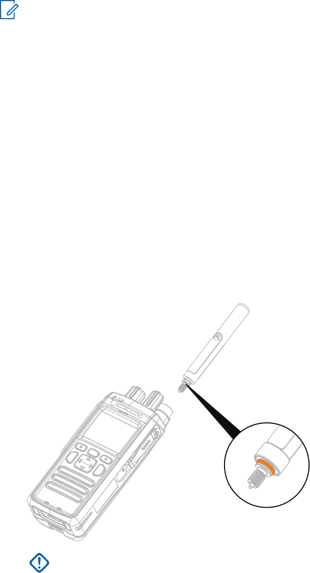
2.2.1
Attaching the Antenna
Procedure:
1Insert the screw-in base of the antenna into the antenna terminal on the top of the radio.
2Turn clockwise until tight.
IMPORTANT: Use only the antenna intended for the radio. Make sure that the antenna
has an operating frequency engraving and a color ring at the bottom of the thread. Use of
other antennas can result in significant range loss due to poor RF performance.
MN001488A01-BF (en-US)
Getting Started
20
DRAFT
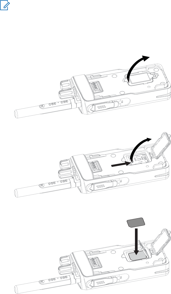
2.2.2
Inserting the SIM Card
NOTICE: MTP3500 800MHz and MTP3550 800 MHz are not fitted with a SIM latch.
Prerequisites: Turn off your radio before inserting the SIM card.
Procedure:
1Remove the battery.
2Open a plastic SIM card cover.
3Slide a SIM card latch towards the bottom of the radio and lift the latch.
4Place the SIM card in a socket with the contact area facing down. Pay attention to the correct
position of the notched corner.
5Close the SIM card latch and slide it towards the top of the radio.
6Close the plastic SIM card cover.
7Replace the battery.
MN001488A01-BF (en-US)
Getting Started
21
DRAFT
2.2.3
Installing the Battery
Procedure:
1Insert the battery into the compartment.
2Slide the battery towards the top of the radio until it clicks.
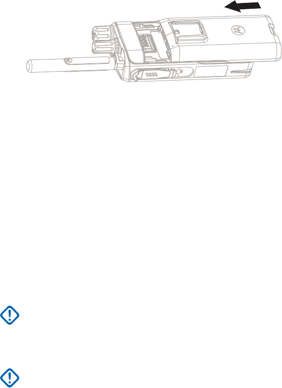
2.2.4
Removing the Battery
Prerequisites: Turn off the radio.
Procedure:
1Push up and hold the latch at the bottom of the battery.
2Slide the battery toward the bottom of the radio.
2.2.5
Charging the Battery
You can charge a battery separately or attached to a radio.
Charging a battery attached to a radio must be done with the radio turned off. The battery charges
faster when the radio is turned off.
IMPORTANT: Use only Motorola Solutions approved-chargers which provide optimal
performance. Using other chargers may fail to fully charge, or reduce the life of the battery.
Prerequisites:
Do not charge the battery in a hazardous area.
IMPORTANT: Do not connect a radio without a battery to the charger.
Procedure:
1Connect the charger to an appropriate power source, according to the specification of the
charger.
2Perform one of the following actions:
•Desktop chargers – insert the battery or the radio with the battery attached into the
appropriate socket of the charger. Ensure that the battery/radio made good connection with
the charger and that the LED on the charger is indicating that charging is in progress.
• Travel chargers and car chargers – connect the charger to the radio with the battery
attached. Ensure that the charger is firmly connected to the radio and that the radio display is
indicating that charging is in progress.
MN001488A01-BF (en-US)
Getting Started
22
DRAFT
NOTICE: If a multi-unit charger LED indicates an error (blinking red light) when radio is
inserted and being charged with the multi-unit charger (MUC), re-insert the radio. If the
light is still red after several reconnections to MUC, the battery may be damaged or
reached its end of life.
Postrequisites: The battery may heat up during charging. After charging, make sure that the battery
and the radio are within the operating temperature range before using the radio.
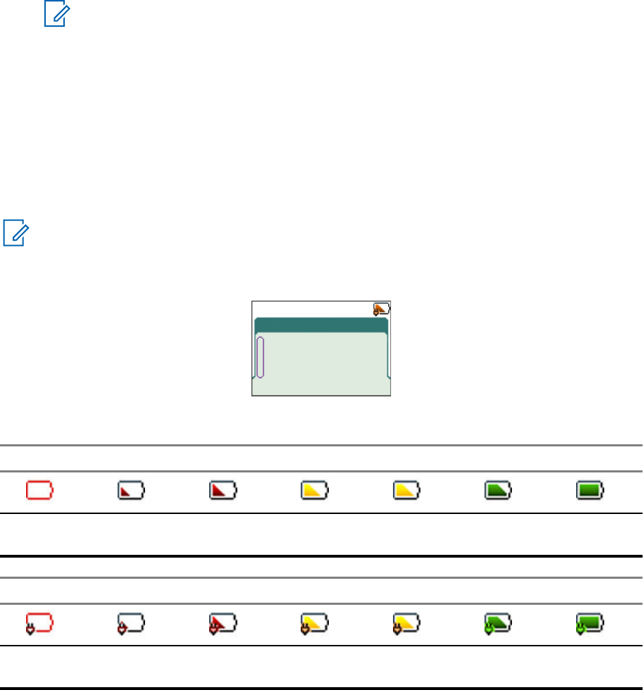
2.2.6
Battery Charging Indications
When the radio is charging, it displays the Charger Mode screen. The screen displays an appropriate
Battery Charge Progress icon and charging progress expressed in percentage.
NOTICE:
To easily identify the charging status, check the Battery Charging LED Indicator. See LED
Indications on page 141.
Figure 1: Charger Mode Screen
Charger Mode
Charging: 35%
Table 3: Battery Icons
Battery Capacity
0%–5% 5%–15% 15%–25% 25%–40% 40%–60% 60%–80% 80%–
100%
Battery Charge Progress
0%–5% 5%–15% 15%–25% 25%–40% 40%–60% 60%–80% 80%–
100%
2.2.7
Low Battery Indication
The radio indicates low battery level by playing an audible alert when the battery charge falls to a
preset level. The low battery alert can be programmed to be 5, 10, or 20 % of remaining capacity by
your service provider. The default setting is 5 %. The service provider also configures how frequently
the alert repeats.
2.3
Controls and Indicators
MN001488A01-BF (en-US)
Getting Started
23
DRAFT
5
7
3
8
10
9
11
6
5
4
2
1
14
16
7
17
15
13
12
18
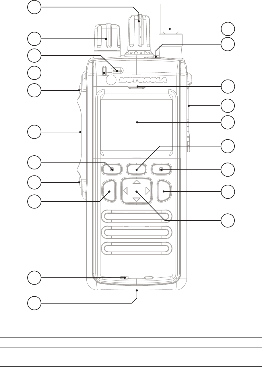
Table 4: Controls and Indicators
Annotation Description
1Talkgroup Knob
Rotate to select a different talkgroup.
2Volume Knob
MN001488A01-BF (en-US)
Getting Started
24
DRAFT

Annotation Description
Rotate to set the volume.
3 Top Microphone
Activated during Simplex, high audio calls such as Group Calls.
4 LED
5Programmable Side button
Programmable button, by default, the upper Programmable Side button is set
to the Flip Display feature and the lower Programmable Side button is set to
the Hi/Low Audio feature.
NOTICE: The required time to press and hold Programmable Side
button to activate a One-Touch Button feature is set as default to 0,1
second.
6Push-To-Talk (PTT)
•Press and hold to talk in simplex calls or to initiate a group call, release it to
listen.
• Press to send status and text messages.
7 Soft key
Press Left or Right Soft key, to select the option that appears on the screen
directly above them.
8Send key
Press to initiate or answer duplex calls, or send messages.
9 Bottom Microphone
Activated during Duplex, low audio calls such as Private Calls.
10 Charger Connector
Provides connection for programming and data transfer.
11 Antenna
12 Emergency button
Press and hold Emergency button to enter Emergency operation. When your
radio is off, press and hold to power on in Emergency Mode.
13 Earpiece
Activated during Duplex calls.
14 Accessory Connector
Provides connection for accessories.
15 Display
Provides alphanumeric text and images within 65,536 colors and 132x90 pixels
with scalable fonts and contrast.
NOTICE: The Display can be in color and grayscale mode.
16 Menu key
•From the home screen, press to enter the main menu.
• Used to enter the context-sensitive menu.
MN001488A01-BF (en-US)
Getting Started
25
DRAFT
Annotation Description
17 On/Off/End/Home key
•Press and hold to turn on/off your radio.
• Press to end calls.
• Press to return to the home screen.
NOTICE: If a message or notification is displayed on the radio
and the Screen Saver activates, pressing On/Off/End/Home only
deactivates the Screen Saver.
18 Navigation key
Press Up, Down, Left or Right Navigation key for list scrolling, while moving
around the menu hierarchy, or for alphanumeric text editing.
From the home screen, press to activate one of the following:
•Down Navigation key – enters Recent Calls menu item.
•Up Navigation key – changes My Groups talkgroup folder.
•Left and Right Navigation key – toggles through the talkgroups.
NOTICE: A detailed list of compatible accessories is included in Accessory Leaflet, part
number: 68015000843. To obtain the document, contact your service provider.
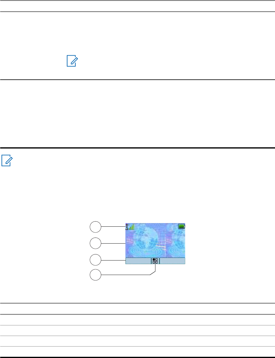
2.4
Display
This section presents the default home screen elements of the radio.
Figure 2: Default Home Screen with Icons
1
2
3
4
Home Mode
Network
Range
Options Contcs
Table 5: Display
Annotation Description
1 Status icon area
2 Text display area
3 Soft key area
4 Menu/Context sensitive icon
MN001488A01-BF (en-US)
Getting Started
26
DRAFT

The color of the Soft key area changes according to the mode the radio is in.
Table 6: Colors of the Soft Key Area
Color Mode or State
Light blue Normal TMO and DMO Modes
Light red Emergency Mode or Disaster Alert Call
Olive Local Site Trunking Mode
Yellow Call Out – Standby
Red Call Out – Alert
Green Call Out – Accepted
Blue Radio Messaging Service (RMS)
Gray Radio User Assignment (RUA) – Limited service
2.4.1
Configurable Idle Screen
Your service provider can configure the information that is displayed on the idle screen below the
status icon area. The displayed information depends on the radio configuration and services
supported.
•Audio Profile Name
• BSI Registration Status
• Home Mode
• Individual Short Subscriber Identity (ISSI)
• International Talkgroup Link Alias
• Network (No Service, or Mobile Country Code (MCC)/Mobile Network Code (MNC), or Networks
Alias)
• Operational-Tactical Address (OPTA)
• Radio Status
• Range
• RMS/FMS
• RMS messages
• Scan List Alias
• Secondary Talkgroup Alias
• Talkgroup Alias
• Time and Date
Order and visibility of these items are also subject of the Configurable Idle Screen settings.
MN001488A01-BF (en-US)
Getting Started
27
DRAFT
2.5
Status Icons
Status icons appear when your radio is engaged in certain activities or when you have activated certain
features.
Depending on the current mode, the size of the UI icons is reduced to allow for more lines of text to be
entered.
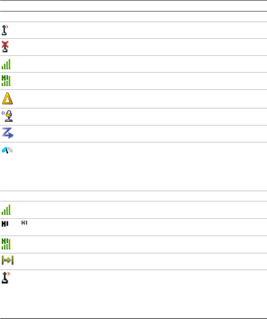
Table 7: Status Icons
Icon Description
Trunked Mode Operation (TMO)
In Service
No Service
Signal Strength – The more bars, the stronger the signal.
RF Power – Indicates that High RF Power is enabled. Shows the signal strength.
The more bars, the stronger the signal.
Migration – Indicates that the radio is registered to a foreign network.
Broadcast Call – Indicates that the radio is in a Broadcast Call.
Scan – Indicates that talkgroup scanning is activated in the radio.
Packet Data or Multi-Slot Packet Data (MSPD) – The more blue sections on the
icon, the faster the data transfer. Possible status:
•Four gray sections: context activated – data idle
• One blue: Packet Data active
• Two blue: Multi-Slot Packet Data active
Direct Mode Operation (DMO)
Direct Mode Call – Indicates that the radio is receiving a Direct Mode call. The more
bars, the stronger the signal.
or
High RF Power: idle or transmitting – Indicates High RF Power option is enabled
and the radio is either in idle mode or is transmitting a call.
High RF Power: receiving – Indicates High RF Power option is enabled and the ra-
dio is receiving a call.
Direct Mode – Indicates that radio is in Direct Mode (radio-to-radio communication).
DMO Gateway Communication Mode – Indicates that gateway is selected. The icon
has the following status:
•Solid – when the radio is synchronized with the gateway.
• Blinking – when the radio is not synchronized or during attachment.
• No icon – during radio-to-radio and repeater communication.
MN001488A01-BF (en-US)
Getting Started
28
DRAFT
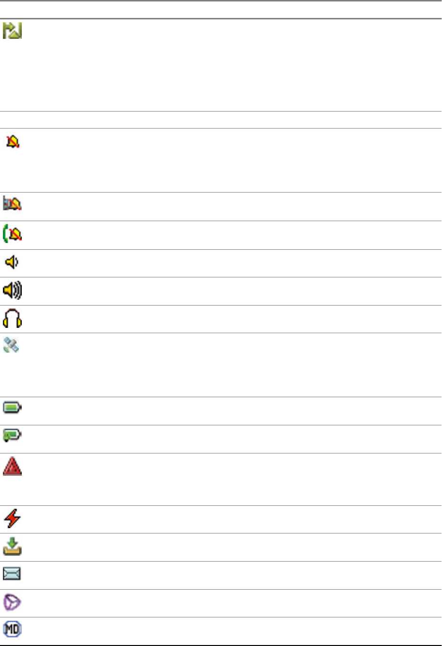
Icon Description
DMO Repeater Communication Mode – Indicates that the Repeater or GW + Rep
option in DMO Mode is selected. The icon has the following status:
• Solid – when the radio has detected the repeater (for example, when the radio
receives a presence signal).
• Blinking – when the radio has not detected the repeater or during attachment.
• No icon – during a radio-to-radio and gateway communication.
General Icons
All Tones Off – Indicates that:
•Volume is set to 0 (when Volume Adj. Mode is set to Common).
• Both simplex and duplex ring volume is set to 0 (when Volume Adj. Mode is set
to Individual).
Simplex Ring Muted – Indicates that simplex ring volume is set to 0 and duplex ring
volume is set to more than 0.
Duplex Ring Muted – Indicates that duplex ring volume is set to 0 and simplex ring
volume is set to more than 0.
Low Audio – Indicates that the audio mode is changed to low.
High Audio – Indicates that the audio mode is changed to high.
Earpiece Connected – Indicates that the earpiece is connected.
GNSS
•Solid – the radio has a location fix.
• Blinking – the radio is acquiring a location fix. This feature is an optional setting
and may not be enabled on your radio.
Battery Strength – Shows the charge of your battery.
Battery Charging – Indicates that the battery is charging.
Emergency – Indicates that the radio is in Emergency Operation.
•Solid – Emergency Operations initiated.
• Blinking – the radio is in emergency receiving state.
Disaster Alert Call – Indicates that the radio is in Disaster Alert Call.
New Message Has Arrived – Indicates that a new message has arrived.
New Message in Inbox – Indicates that you have unread messages in your Inbox.
Unread (New) WAP Message – Indicates that new page was loaded to the browser.
Man Down Active – Indicates that the Man Down feature is active.
MN001488A01-BF (en-US)
Getting Started
29
DRAFT
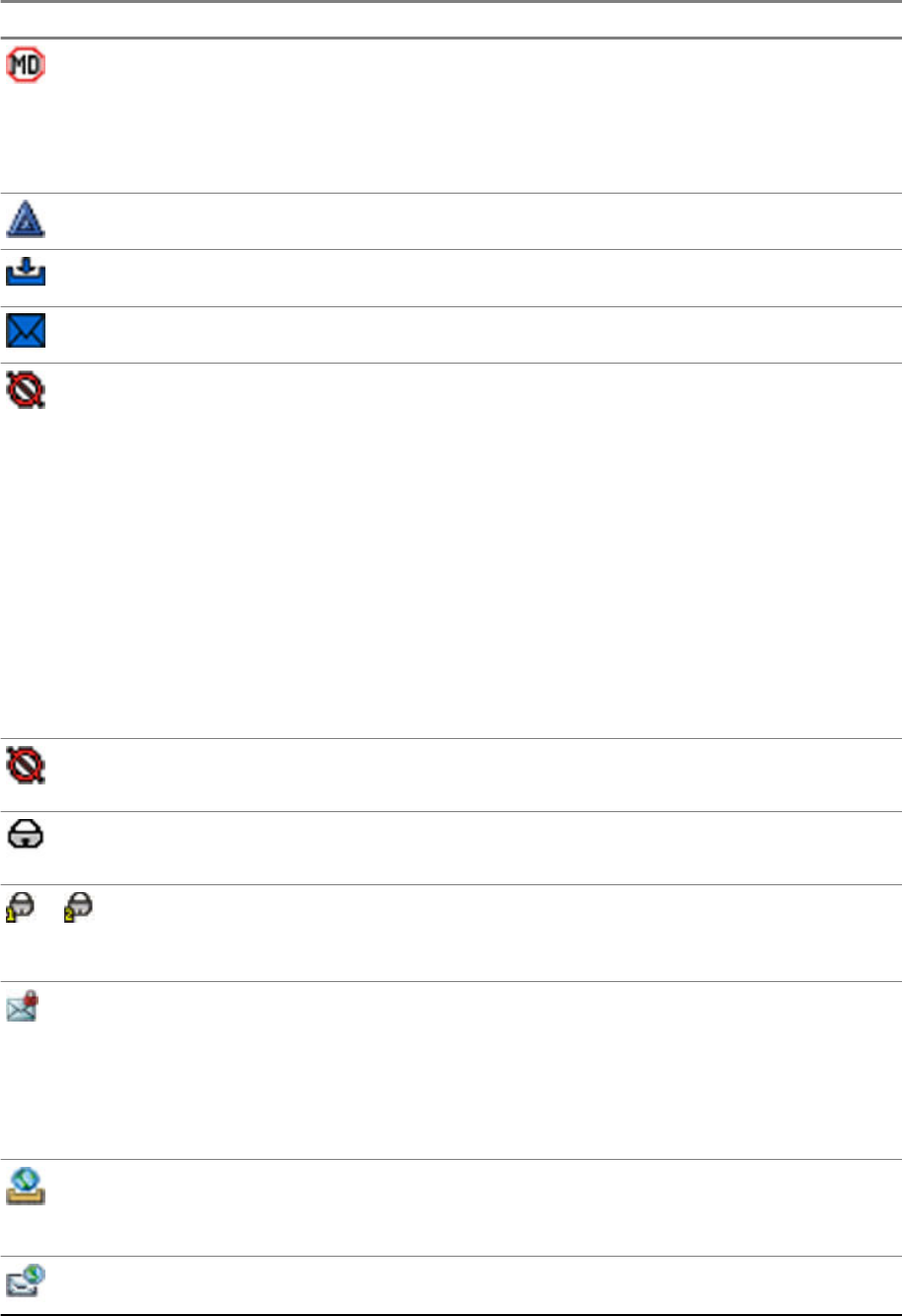
Icon Description
Man Down Alert – Indicates that the Man Down feature is active. This icon has the
following status:
•Blinking – pre-Alert; the radio signalizes Man Down conditions. To exit the pre-
Alert state, change the conditions or press the PTT button.
• Solid – the radio enters Alert mode.
Call-Out – Indicates Call-Out alert.
Call-Out Alert Arrived – Indicates a receipt of a new Call-Out message.
Call-Out Alert Unread – Indicates unread alert in the CO Box.
End-to-End Encryption (E2EE)
Solid, when the E2EE is enabled:
•for the selected talkgroup,
• for the highlighted private number,
• for the manually entered private number,
• when transmitting voice in Group Calls,
• when transmitting voice in Simplex Private Calls.
Blinking, when the E2EE is enabled:
• when receiving voice in Group Calls,
• when receiving voice in Simplex Private Calls,
• during encrypted Duplex Private Calls.
Encryption Off
Blinking – Indicates that the SIM Card E2EE is disabled in DMO and TMO Modes.
SIM End-to-End Encryption (E2EE) in TMO
Indicates that the SIM Card E2EE is enabled in TMO Mode.
or SIM End-to-End Encryption (E2EE) in DMO
Indicates that the SIM Card E2EE is enabled in DMO Mode. Numbers 1 and 2 point
to the type of DMO Encryption keys that has been selected.
SDS End-to-End Encryption (E2EE)
Indicates the E2EE status of an SDS message, or the E2EE status of a message
recipient address.
In High Security mode, when your radio processes only the encrypted information,
this icon is always visible in when you are in the messages menu, for example, In-
box.
Unread (New) WAP Message – Indicates that you have not entered WAP Box since
last WAP message was received.
Blinks when the priority is high.
WAP Message Icon – Displayed next to the priority WAP message in the message
list view.
MN001488A01-BF (en-US)
Getting Started
30
DRAFT
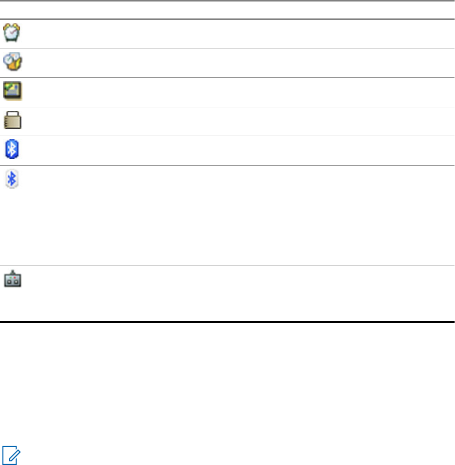
Icon Description
WAP Message Time – Displayed next to the create date in the message list view.
WAP Message Expiration – Displayed next to the expiry date in the message list
view.
WAP Message Title Icon – Displayed next to the title along with the text in the mes-
sage list view.
Keys Locked – Indicates that keys are locked.
Bluetooth Connected – Indicates that Bluetooth is enabled and at least one device
is connected.
Bluetooth Disconnected
•Solid – Indicates that Bluetooth is enabled, but no device is connected.
• Blinking indicates one of the following:
- Bluetooth is enabled and the radio is in the Discoverable Mode.
- Bluetooth is enabled and a connection with a remote device is being estab-
lished.
Remote Control – Indicates that the radio is being remotely controlled and some
commands are being executed in the background. For example, when the radio is
being controlled by special SDS messages or triggered to send a GNSS location re-
port.
2.6
Powering On the Radio
Procedure:
Press and hold On button.
Your radio performs a self-check and registration routine.
After successful registration, your radio is in service.
NOTICE: Your radio powers on without visible and audible notification if Covert Mode is
activated.
2.7
PIN Code Authentication
If pre-set by your service provider, the radio has active PIN Code Authentication, which helps you
increase security and protect your radio against unauthorized use.
The PIN code is read from the SIM card or radio programming and cannot be changed or disabled. If
you are unable to unlock the radio, you cannot send or receive any call, nor adjust the volume level
with the Rotary Knob.
You are asked to enter the PIN code each time you turn on the radio.
MN001488A01-BF (en-US)
Getting Started
31
DRAFT

2.7.1
Unlocking Your Radio
Your radio may be locked at power up. To unlock it after powering on, enter the code at the prompt.
Your radio enters the default home display.
NOTICE: The unlock code is originally set to 0000. Your service provider may change this
number before you receive your radio.
2.7.2
Unblocking Your Radio
If you have entered the incorrect PIN code for more than three times (by default), use the Personal
Unblocking Key (PUK) to unblock your radio.
Procedure:
1Radio displays Unit Blocked Enter PUK.
2Enter the eight–digit PUK number.
NOTICE: The PUK is an eight-digit master code provided by your service provider.
3Enter the new PIN code twice.
2.8
Locking or Unlocking the Keys or Buttons
Procedure:
2.9
Holding Your Radio
Your radio has two microphones: a top microphone for simplex dispatcher/private calls and a bottom
microphone for duplex telephone-like calls.
The radio is also equipped with an internal speaker for high audio (located at the middle of the unit)
and an internal earpiece for low audio (located at the top of the unit). The audio can be routed either to
the speaker or the earpiece using the Audio Toggle menu (Menu → Setup → Audio → Audio
Toggle) or the assigned One-Touch Button.
NOTICE: For best performance speak directly into the top microphone.
Simplex Calls
When using high audio, hold your radio a vertical position with its top microphone 5–10 cm away from
your mouth. Speak into the top microphone. Listen through the internal speaker. Keep the antenna at
least 2.5 cm from your head and body.
MN001488A01-BF (en-US)
Getting Started
32
DRAFT

Duplex Calls
When using low audio, hold your radio as you would a telephone. Speak into the bottom microphone.
Listen through the earpiece. Keep the antenna at least 2.5 cm from your head and body.
Lapel/Shoulder Use
For Group and Private Calls turn your head towards your shoulder/lapel, and speak directly into the top
microphone. Listen through the internal speaker.
Speakerphone Use
Place your radio 30–60 cm away from you. In a noisy environment, move the radio closer to you for
better transmission.
2.10
High or Low Audio Toggle
Your radio is able to switch from the external earpiece to the main speaker using One-Touch button
and is not required to disconnect the external earpiece or PHF.
The states of the routed audio are:
•Speaker HIGH – indicates that audio is routed to the main speaker.
•Speaker LOW – indicates that audio is routed to the earpiece or PHF earpiece, and not to the main
speaker.
2.10.1
Using High Audio
When and where to use: Placing or receiving a Phone, PABX, or Duplex Private call.
Procedure:
1Hold your radio in a vertical position with its top microphone 5 cm to 10 cm away from your
mouth.
2Speak into the top microphone and listen through the internal speaker.
Keep the antenna at least 2.5 cm from your head and body.
2.10.2
Using Low Audio
When and where to use: Placing or receiving a Phone, PABX, or Duplex Private call.
Procedure:
1Hold your radio as you would a telephone.
2Speak into the bottom microphone and listen through the earpiece.
Keep the antenna at least 2.5 cm from your head and body.
MN001488A01-BF (en-US)
Getting Started
33
DRAFT

2.11
During a Call
During the call, label of the right Soft key indicates the next possible change. Accessory default setup
is:
Table 8: During the Call
Soft Key Label Audio Setting
Spkr Audio goes to the main speaker (Speaker HIGH is displayed)
Erpce Audio goes to the earpiece (Speaker LOW is displayed)
PHF Audio goes to the Personal Hands Free (Speaker LOW is displayed)
2.12
Entering TMO or DMO Mode
Procedure:
1From the home screen, press Options.
2Select Trunked Mode/Direct Mode.
2.13
Selecting Talkgroups
Follow these procedures to select talkgroup manually. If the selected talkgroups is an InterSystem
Interface (ISI) talkgroup, your radio can migrate to another talkgroup linked network, changing the
talkgroup automatically.
Procedure:
From the home screen, use one of the following methods:
•Press Left or Right Navigation key. Press Select to confirm.
• Select Options → TG by abc. Enter a talkgroup name and select the talkgroup name from the
list.
• Select Options → TG by Folder. Select a folder (for example, Favorite) and then a talkgroup
name.
NOTICE: Your radio can access up to three levels of the folder structure.
• Rotate Talkgroup Knob until the required talkgroup name is displayed.
2.13.1
Talkgroup Icons Selection
Talkgroup icons are used to indicate that a talkgroup has a special function, show the status of network
selection, and/or show the talkgroup properties. A talkgroup without an icon does not have a special
function attached to it.
MN001488A01-BF (en-US)
Getting Started
34
DRAFT
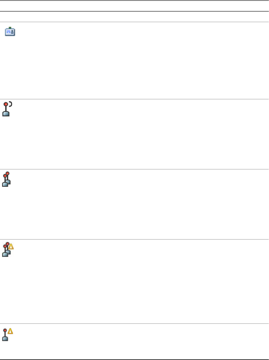
These icons are displayed next to the talkgroup alias on idle display and when scrolling talkgroups in
common or favorite folder lists.
Table 9: Talkgroup Icons
Icon Talkgroups in Common Folders Talkgroups in Favorite Folders
TMO Talkgroup Icons
In TMO Mode
Display when the talkgroup selected is
a SIM TMO talkgroup, and not regis-
tered to SIM network.
Single network is available.
In TMO Mode
Display when the talkgroup selected is
a SIM TMO talkgroup, and not regis-
tered to SIM network.
Single network is available.
In DMO Mode
Display when the talkgroup selected is
a SIM TMO talkgroup.
Single network is available.
Not displayed in common folders. In TMO Mode
Display when the talkgroup selected is
a normal TMO talkgroup.
Single network is available.
In DMO Mode
Display when the talkgroup selected is
a normal TMO talkgroup.
Single network is available.
In TMO Mode
Display when the talkgroup selected is
an ISI or Any network TMO talkgroup.
Multiple networks are available.
In TMO Mode
Display when the talkgroup selected is
an ISI or Any network TMO talkgroup.
Multiple networks are available.
In DMO Mode
Display when the talkgroup selected is
an ISI or Any network TMO talkgroup.
Multiple networks are available.
In TMO Mode
Display when TMO ISI talkgroup se-
lected is not assigned to home net-
work.
Multiple networks are available.
In TMO Mode
Display when TMO ISI talkgroup se-
lected is not assigned to home net-
work.
Multiple networks are available.
In DMO Mode
Display when TMO ISI talkgroup se-
lected is not assigned to home net-
work.
Multiple networks are available.
In TMO Mode
Display when the TMO normal talkgroup selected is not assigned to the current
network.
Single network is available.
MN001488A01-BF (en-US)
Getting Started
35
DRAFT
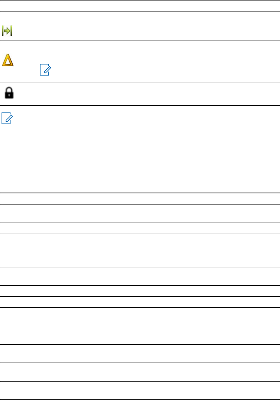
Icon Talkgroups in Common Folders Talkgroups in Favorite Folders
DMO Talkgroup Icons
Display when a DMO talkgroup is selected.
General Icons
Display when the radio is registered to a network that is not the home network.
NOTICE: The icon, also known as Migration icon, is only displayed on the
top of the display as a status icon.
Display when the radio is locked to a current network selection that is a single network
while the current selected ISI talkgroup or Any Net talkgroup allows multiple networks.
NOTICE: In common folders, no TMO talkgroups are shown when in DMO mode.
2.14
One-Touch Buttons
The One-Touch Button feature allows you to activate a feature by a long key press of the
programmable button. Your service provider can also assign one-touch functions to the keypad keys.
Table 10: One-Touch Button Features
Feature Description
Access Private Dialing Ed-
itor
Displays the private dialing editor.
Activation of Covert Mode Turns Covert Mode on or off.
Add Bluetooth Device Activates scanning for Bluetooth devices.
Any Network Selects any network.
Any Talkgroup Network Selects any talkgroup network.
Bluetooth Smart Proximity
Pairing
Turns Proximity Pairing on or off.
Call-Out Box Displays the list of call-out sessions.
Change Audio Profile Change to the specific audio profile.
Change Talkgroup Changes the talkgroup to the one programmed by your service pro-
vider.
Direct Private Number Di-
aling
Dials a predefined private number.
Disconnect All Connected
Bluetooth Devices
Disconnects all Bluetooth devices connected to the radio.
Display Bluetooth GATT
Sensors Battery Levels
Displays the battery levels of all paired Bluetooth GATT-based sen-
sor devices.
Display GATT Service Da-
ta
Displays the GATT-based sensor data.
MN001488A01-BF (en-US)
Getting Started
36
DRAFT

Feature Description
Display Heart Rate Displays the heart rate value received from the connected GATT-
based heart rate sensor.
Display Operational-Tacti-
cal Address (OPTA)
Displays the OPTA.
DMO Pre-emptive SDS Sends the next DMO SDS or status message with elevated priority.
Flip Display Rotates the display by 180 °.
Home Only Selects only home network.
Home Talkgroup on Home
Network
Selects only home network and home talkgroup network.
Initiate Call-Out Fallback Sends Call-Out Fallback Alert.
LIP Report Sends a message with the location of the radio to a dedicated ad-
dress.
Lock to Current Network Selects the current network only.
Message Inbox Displays the list of messages in Inbox.
PABX Call Setup Initiates a PABX call to a predefined entry in the contact list.
Phone Call Setup Initiates a phone call to a predefined entry in the contact list.
Prefer Talkgroup Network
Shortcut
Displays the Prefer Talkgroup Network menu.
Private Call Setup Initiates a simplex or duplex private call to a predefined entry in the
contact list or to the last group call originator.
Reset to Default Resets the radio to its default settings.
RMS MMI Menu Opens the RMS menu without activating RMS mode.
RUI Logon or Logoff Asks for the credential or logs off the radio.
Scan for Bluetooth Devi-
ces
Activates scanning for Bluetooth devices once OTB assigned to the
Add Bluetooth Device function is pressed.
Select Talkgroup Network
Shortcut
Displays the Select Talkgroup Network menu.
Selecting Audio Profiles Scrolls through all available audio profiles.
Send Double Push PTT
Tone (D-PTT)
Sends the D-PTT tone to the currently used talkgroup.
Send Predefined Template
(PDT)
Sends a predefined message to a dedicated address.
Send Status Message Sends a dedicated status message to a dedicated address.
Send User-Defined Tem-
plate (UDT)
Sends a user-defined message to a dedicated address.
Switch to Previously Se-
lected Talkgroup
Changes the talkgroup of the radio to the previously selected talk-
group (DMO or TMO).
Timed Talkgroup Change Makes a predefined talkgroup the selected talkgroup for a specified
amount of time. While using the predefined talkgroup, the second
press of the One-Touch Button results in:
MN001488A01-BF (en-US)
Getting Started
37
DRAFT

Feature Description
• the radio returning to the previously selected talkgroup,
•the radio restarting the predefined time, or
• no action on the radio, depending on the configuration
After the timer expires, the radio returns to the previously selected
talkgroup.
Toggle Backlight Toggles the backlight on or off.
Toggle Backlight Intensity Regulates the backlight intensity.
Toggle Bluetooth Discov-
erable Mode
Turns Discoverable Mode on or off.
Toggle Bluetooth GATT
Sensor MMI Alerts
Toggles Bluetooth GATT Sensor MMI Alerts on or off.
Toggle BSI Encryption En-
abled or Disabled
Enables or disables BSI encryption.
Toggle Call Forwarding Toggles Call Forwarding on or off.
Toggle DMO or TMO Toggles between TMO and DMO modes.
Toggle Extra Zoom Turns Extra Zoom on or off.
Toggle Hi or Low Audio Toggles audio high or low.
Toggle Howling Suppres-
sion
Enables or disables Howling Suppression.
Toggle Man Down On or
Off
Turns Man Down feature on or off.
Toggle RF Power Class Toggles the RF Power Class between High and Normal.
Toggle Rotary Knob Lock Locks or unlocks the Rotary Switches.
Toggle RSM with Earpiece Activates or deactivates the RSM earpiece.
Toggle Screen Saver Activates or deactivates the Screen Saver feature.
Toggle Talkgroup Scan Turns the Talkgroup Scan feature in TMO Mode on or off.
Toggle Transmit Inhibit
Mode (TXI)
Turns TXI on or off.
Turn Bluetooth Indoor Lo-
cation On or Off
Activates Bluetooth Indoor Location.
Turn Bluetooth On or Off Turns Bluetooth on or off.
Turn Repeater Mode On
or Off
Turns Repeater Mode on or off.
Unassigned The radio displays Unassigned Button when no feature assigned
to this button.
Universal Time Display Displays universal time on the home screen.
Volume Down Press to decrease the volume by one level. Press and hold to contin-
uously decrease the volume to its minimum level.
Volume Up Press to increase the volume by one level. Press and hold to contin-
uously increase the volume to its maximum level.
MN001488A01-BF (en-US)
Getting Started
38
DRAFT
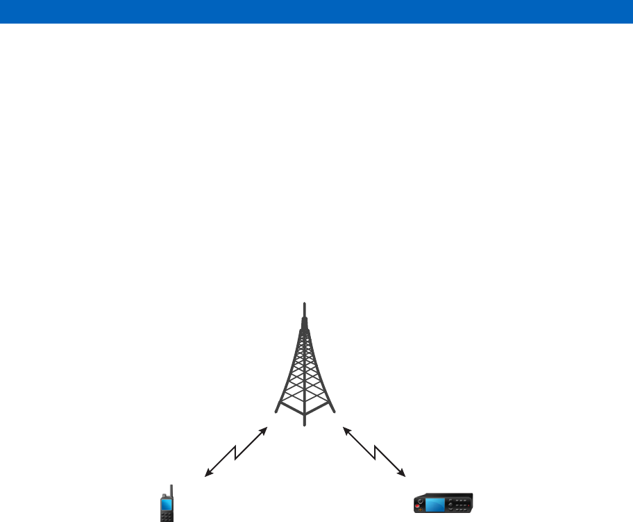
Modes
This chapter contains information on available modes that the radio can operate in.
3.1
Trunked Mode Operation
Trunked Mode Operation (TMO) requires the switching and management infrastructure.
This operation mode enables various voice and data communication types, such as group calls and
short data service messages, as well as access to the infrastructure-related features such as packet
data.
Figure 3: Trunked Mode Operation
3.1.1
Entering TMO Mode
Procedure:
1Do one of the following:
• From the home screen, press Options.
• From the home screen, press the Menu key. Select Networks.
2Select Trunked Mode.
3.1.2
Making Group Calls in TMO
The Group Call is received by all members of the selected group who have their units turned on and
are connected through the network.
Procedure:
1Press and hold the PTT button.
MN001488A01-BF (en-US)
Modes
39
DRAFT

2Wait for the Talk Permit tone (if configured) and then speak into the microphone. Release the
PTT button to listen.
3.1.3
Receiving Group Calls in Idle
Procedure:
1Your radio receives a Group Call.
NOTICE: The incoming Group Call is signaled by a Receiving Group Call tone.
2To respond, press and hold the PTT button.
3.1.4
Receiving Group Calls during Ongoing Group Calls
While in active Group Call, your radio receives a Group Call with a higher priority.
One of the following occurs:
•Your radio is forced to end the current group call and automatically join the incoming one.
• Your radio displays incoming group call screen with options:
-Join – ends current Group Call and starts the incoming one.
-End – cancels the incoming Group Call.
3.1.5
Dynamic Group Number Assignment (DGNA)
DGNA allows the network operator to dynamically manage talkgroups on your radio over the air
interface. Using DGNA, the network operator can:
• Add talkgroups.
• Attach or select newly added talkgroups.
• Delete talkgroups.
• Modify parameters of existing talkgroups.
All the above operations are performed by transmitting data to your radio.
3.1.5.1
DGNA Reception
When a DGNA message is received, your radio plays a tone and displays a message Talkgroup
list updated. If enabled by your service provider, your radio displays all added and deleted
talkgroup list.
When your service provider deletes (de-assigns) the currently selected talkgroup, depending on the
settings, your radio can perform one of the following actions:
• Enter the “No Group” state – your radio does not attach to any talkgroup automatically.
• Attach to the last selected TMO talkgroup. If the last selected TMO talkgroup is not available (it was
deleted), your radio enters the “No Group” state.
• Attach to a default talkgroup configured by your service provider. If the default talkgroup is not
available (it was deleted), your radio enters the “No Group” state.
At each talkgroup change, an appropriate notification is shown on the display.
MN001488A01-BF (en-US)
Modes
40
DRAFT

If the DGNA message is received to delete all talkgroups, your radio displays All Talkgroups
Deleted. To exit the DGNA display, you can use the Back Soft key or the End key.
3.1.5.2
DGNA Auto Select Group
If the DGNA Auto Select is configured, whenever your radio receives a DGNA, it switches to the added
talkgroup.
3.1.5.3
DGNA Auto Reselect Group
If the DGNA Auto Reselect is configured, whenever a talkgroup assigned by the network operator
through the DGNA is deassigned without the user action, the radio returns to the previously selected
group.
3.1.5.4
Viewing DGNA Talkgroups
Prerequisites: Your radio receives the DGNA message.
Procedure:
1To view the added talkgroups details press View.
2Scroll through the list to select required talkgroup.
3To select the DGNA group, press Attach.
3.1.6
Broadcast Call
Broadcast Group Call (also called Site Wide Call) is a high-priority group call from the console operator
(or dispatcher) to all users located at one or more sites. The radios are configured to monitor a
Broadcast Call, but you cannot talk back. The call can be received as a normal Broadcast Call or an
Emergency Broadcast Call. The Broadcast Call preempts an ongoing Group Call that has the same or
lower call priority.
3.1.6.1
Broadcast Calls Initiated by Users
This feature allows you to make a Broadcast Call from the radio that is initiated on the predefined
talkgroup. Your service provider predefines the alias and the priority of the Broadcast Call.
NOTICE: If the type of the encryption is defined by the SIM Card, the Broadcast Call is always
clear. Otherwise if the radio uses other encryption service the type of the encryption used for
that Call is up to the encryption settings of that service.
This feature is not supported on the Dimetra infrastructure.
3.1.6.2
Initializing Broadcast Calls
Procedure:
1From the home screen, press the Menu key.
2Select Services → Broadcast.
Your radio displays the predefined alias and the Broadcast Call icon.
MN001488A01-BF (en-US)
Modes
41
DRAFT

3To start the call press the PTT button.
3.1.7
Phone and Private Automatic Branch Exchange (PABX) Calls
Phone Call allows you to call a landline telephone number or a cellular mobile phone number. Private
Automatic Branch Exchange (PABX) Call allows you to call local (office) extension numbers.
3.1.8
Assistance Call
This feature allows you make a private call to ask for assistance during normal and non-critical
situations.
NOTICE: Your service provider can configure the number, priority, and the type of the call
(simplex or duplex).
3.1.9
Call Modification
Call Modification is a feature that allows your service provider to modify the call to optimize it and
adjust to a current situation.
Modification can cover:
Call priority
Modified during call setup.
Call type
Modified during call setup.
Call encryption
Modified during an ongoing call, but not in the transmission phase.
When the call is modified, your radio displays Call Modified message.
When a recently modified call requires the PTT button to transmit, your radio displays Call
Modified Use PTT.
All modifications are made by your service provider and the radio only follows them. You have no
influence on ongoing call modifications.
When call priority is changed to emergency:
• The display indicates that an Emergency Group Call has been received.
• The radio plays a special audio alert.
NOTICE: If a Group Call is modified into an Emergency Group Call, no emergency-related
features are triggered.
If the radio cannot follow a call modification requested by the service provider, due to its settings, the
radio rejects it and displays Service Not Available message.
3.2
Local Site Trunking
This mode is also called as Fallback Mode and it allows more than one radio from the same site to
communicate when the link between the site and the network central controller fails. Entering and
exiting Local Site Trunking (that is, returning to System Wide Services) is done automatically. In this
mode, some services are unavailable.
MN001488A01-BF (en-US)
Modes
42
DRAFT

NOTICE: Your service provider can disable this mode.
3.2.1
Entering Local Site Trunking
When your radio receives a Local Site Trunking indication from the system, the following occurs:
•Your radio plays an Entering Local Site Trunking tone.
• Display shows the Local Area Service message.
• Display icons and soft keys turn olive.
NOTICE: Noticeable only on the color display.
• Any call in progress is dropped upon entering Local Site Trunking Mode.
If configured by your service provider, this message/alert is periodically repeated to remind you that
your radio is still operating in Local Site Trunking Mode. The following features are available:
•Registration
• Attachment
• Group Call
• Emergency Call
• Emergency Alarm
3.2.2
Exiting Local Site Trunking
When the link with the central network controller is reestablished, your radio exits Local Site Trunking,
and the following occurs:
• Your radio plays an Exiting Local Site Trunking tone.
• Any call in progress during Local Site Trunking is dropped.
• Display icons and soft keys turn blue.
MN001488A01-BF (en-US)
Modes
43
DRAFT
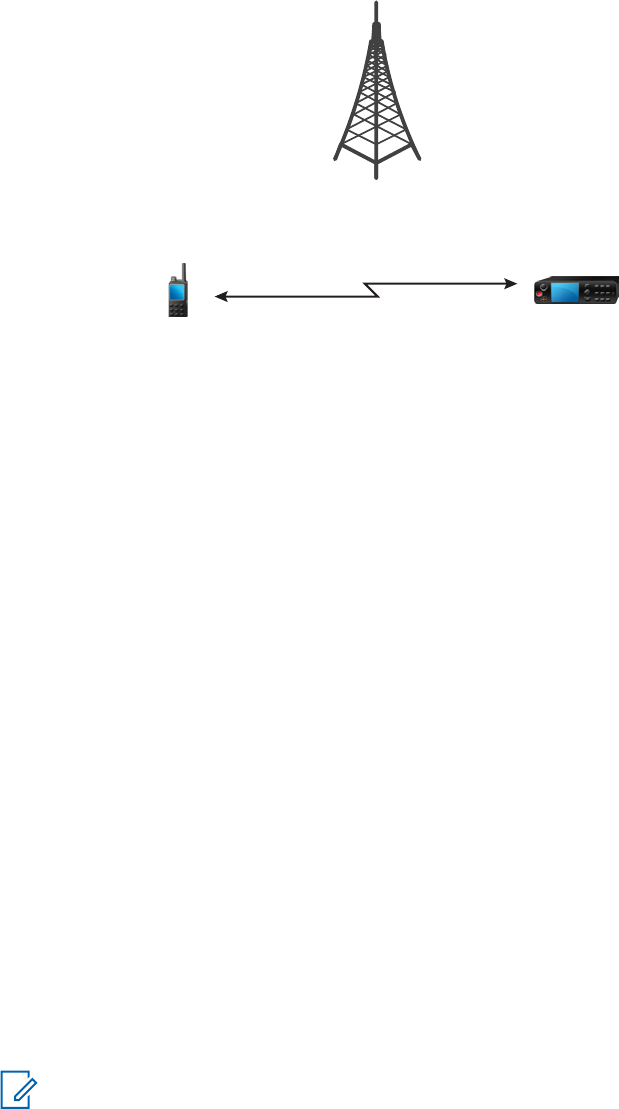
3.3
Direct Mode Operation
Direct Mode Operation (DMO) is a mode of simplex operation where radios communicate directly
without the need of a network.
Figure 4: Direct Mode Operation
3.3.1
Entering DMO Mode
Procedure:
To enter the DMO Mode:
• From the home screen, press the Menu key. Select Networks → Direct Mode.
• From the home screen, press the Menu key. Select Options → Direct Mode.
3.3.2
Making Group Calls in DMO
The Group Call is received by all members of the selected group who have their units turned on and
are in range.
Procedure:
1Press and hold the PTT button.
2Wait for the Talk Permit tone (if configured) and then speak into the microphone. Release the
PTT button to listen.
3.3.3
Receiving Group Calls in Idle
Procedure:
1Your radio receives a Group Call.
NOTICE: The incoming Group Call is signaled by a Receiving Group Call tone.
2To respond, press and hold the PTT button.
MN001488A01-BF (en-US)
Modes
44
DRAFT

3.3.4
Selecting DMO Communications Options
When and where to use: Helps to communicate with other radio users on the same talkgroup through
the Gateway or Repeater.
Procedure:
1From the home screen, press Options.
2Press Config.
3Select one of the following:
•MS - MS – Your radio can communicate only with other radios within its range.
•Gateway – Your radio uses a gateway to communicate with the infrastructure.
•Automatic – Your radio uses the first available gateway for that talkgroup.
•Specific – Your radio uses only the Gateway with the specified Gateway address for that
talkgroup. If your radio displays Selected Gateway: None, press Edit to enter the
current gateway address.
•Repeater – Uses the first available repeater for that talkgroup.
•GW + Rep – Uses the first available gateway or repeater for that talkgroup.
•Automatic – Uses the first available gateway for that talkgroup.
•Specific – Uses only the Gateway with the specified Gateway address for that talkgroup.
If your radio displays Selected Gateway: None, press Edit to enter the current
Gateway address.
NOTICE:
When the Gateway and the Repeater cannot be communicated even though a
talkgroup to use them is configured, the radio attempts the direct MS-MS
communication.
When your radio detects the appropriate Gateway and/or the Repeater, the Gateway and/or Repeater
icons turns solid, respectively.
3.3.5
DMO Private Priority Call
The service provider may assign Pre-emptive Priority to outgoing DMO Private Calls. If this is the case,
DMO Private Calls from this radio preempt any ongoing calls (with the exception of emergency calls or
ongoing Pre-emptive Priority Private Calls) on the receiving radio, which then displays Call-
preempted.
3.3.6
Talkgroup for Individual Calls
Talkgroup for Individual Calls is a talkgroup that operates on a separate frequency allocated for
individual (private) calls only. Using this talkgroup optimizes frequency resources and helps not to
block other talkgroups. The only supported call types are: private calls and emergency calls (both
private and group). Use this talkgroup each time you need to make a private call.
When you select a Talkgroup for Individual Calls, your radio is not able to receive or initiate any group
or broadcast calls with priority lower than Emergency.
When you have selected a Talkgroup for Individual Calls and press the PTT button to start a Group
Call, the radio:
MN001488A01-BF (en-US)
Modes
45
DRAFT
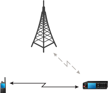
• Rejects the call
•Plays a tone
• Displays the Individual Calls Only message
3.3.7
Network Monitor
This feature allows the radio to monitor for TMO individual calls while maintaining DMO services.
When Network Monitor is active, the radio receives direct calls addressed to the selected DMO
talkgroup, private DMO calls, SDS messages, but also private TMO calls.
The group calls, private calls, and SDS messages initiated are configured in DMO. Only responses to
private TMO calls are sent in TMO.
DMO
TMO
Private Call
3.3.7.1
Enabling Network Monitor
Prerequisites: Ensure your service provider enabled the Network Monitor feature.
Procedure:
1From the home screen, press Options.
2Press Network Monitor.
MN001488A01-BF (en-US)
Modes
46
DRAFT
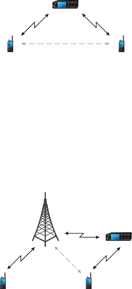
3.3.8
Communication through Repeaters
Radios that are out of range and cannot communicate directly with each other in Direct Mode
Operation (DMO) can do it through the repeater. The repeater is a radio that repeats all communication
on a chosen channel, and as a result increases radios DMO range.
Figure 5: Communication through Repeaters
DMODMO
When the radio connects to a repeater, it plays a tone, displays the Repeater available message,
and shows an appropriate icon. When the radio loses connection with the repeater, it plays a tone,
displays the Repeater not available message, and the repeater icon is blinking.
3.3.9
Communication through Gateways
Gateway provides connectivity between radios operating in Direct Mode Operation (DMO) and the
TETRA network, so that the DMO radios can communicate with the Trunked Mode Operation (TMO)
radios.
Figure 6: Communication through Gateways
DMO
TMO
TMO
MN001488A01-BF (en-US)
Modes
47
DRAFT

When the radio connects to a gateway, it plays a tone, displays the Gateway available message,
and shows an appropriate icon. When the radio loses connection with the gateway, it plays a tone,
displays the Gateway not available message, and the gateway icon is blinking.
3.3.10
Gateway and Repeater Synchronization
To communicate using gateways or repeaters, the radio requires synchronization with a gateway or a
repeater.
A gateway or a repeater sends presence signals to radios. If a radio receives presence signals, it stays
synchronized with the gateway or the repeater which sends the signals. If a radio fails to receive a
presence signal it does not immediately lose synchronization. The radio waits for another successful
presence for a time defined by your service provider. This function ensures that communications are
not dropped due to temporary reception issues.
If a gateway or a repeater is unavailable or the radio is not synchronized with a gateway or a repeater,
depending on the setup configured by your service provider, the following scenarios apply:
• The radio falls back to Direct Mode Operation (DMO).
• After pressing the PTT button, a prompt appears warning that the second press overrides the
gateway or repeater operation mode.
• No direct DMO communications are permitted.
In the second scenario, while the radio receives individual calls and group calls, and replying to
individual calls is possible, replying to group calls is not possible.
3.4
Transmit Inhibit Mode
The Transmit Inhibit (TXI) Mode is a mode in which the radio sends no radio transmissions. Activate
this mode in RF sensitive areas, for example hospitals, airplanes, where safety can be jeopardized due
to transmission radiation.
To activate, select Menu → Networks → TXI Mode → Activate.
In this mode, the radio does not transmit under any circumstances except for the Emergency Calls. All
the functions and keys which cause transmission, for example registration to the network, changing
talkgroup or folder, sending SDS messages, or pressing the PTT button are disabled. Any transmission
trial causes the radio to display Not Allowed In TXI Mode notification and to play a tone.
Your radio can still receive:
• Group calls
• Messages - stored in the Inbox
• Private call attempts - stored in the Missed Calls list, without the option to respond
When no danger to safety exists anymore, for example, when you leave the RF sensitive area, you can
deactivate the TXI Mode and the radio returns to standard operation.
You can deactivate the mode by selecting Menu → Networks → TXI Mode → Deactivate, pressing
One-Touch Button, or implicitly when initiating an Emergency Call.
NOTICE: RF Transmissions from the radio are prevented under the following conditions:
•TXI Mode is activated.
• Battery is removed.
• The radio is turned off.
MN001488A01-BF (en-US)
Modes
48
DRAFT

On entering or exiting the TXI mode, when the radio is camped on a cell, it sends a specially
designated Short Data Service (SDS) status message. This SDS message indicates to the SwMI that
the radio is entering or exiting TXI mode.
Mobility procedures that do not require the radio to send an uplink transmission are performed except
for cell reselection.
In TXI mode, the radio joins group calls for any group that the radio is monitoring, but the transmitting
on that call is still prohibited.
The radio also displays any incoming SDS messages to the user. The missed call feature is active in
the TXI mode and allows checking what calls were missed. However, the radio attempts to prevent call
setup retransmission from being recorded as separate calls.
If you initiate an emergency call, the radio immediately leaves TXI mode and attempts to start the
emergency call if the radio is in service.
If the radio is turned off in the TXI mode, on turning on, the radio asks whether to exit the TXI mode. If
you choose No, the radio turns off.
3.5
Emergency Operations
Emergency Operations are used in critical situations.
Pressing and holding the Emergency button, or entering the Emergency Number and pressing the
Send key, activates one or more services (depending on your service provider settings):
•Emergency Alarm
• SDS Status
• Silent Emergency
• Hot Microphone operation
• Emergency Individual Call (Private or MS-ISDN)
NOTICE: It is possible to turn on the radio by pressing the Emergency button. Depending on
the service provider settings, the radio can start Emergency Operations automatically. If the
radio is PIN-protected (except for SIM PIN), Emergency Operations bypass the PIN lock.
When starting Emergency Operations, any ongoing voice call is aborted or cleared down, and any
packet data transfer in progress is aborted. However, the session is kept open.
During Emergency Operations, the radio rejects phone, PABX, and private calls, and does not monitor
the talkgroups in the selected scan list.
To terminate Emergency Operations, press the Right soft key.
3.5.1
Emergency Alarm
The Emergency Alarm is a special status message sent while starting the Emergency Operations. The
radio sends the message in either TMO or DMO.
Each time the radio enters the Emergency Operation, it sends the Emergency Alarm. When the
Emergency Alarm is sent successfully, the respective audible tone sounds.
In addition, pressing the Emergency button when the radio is in the Emergency Operation resends
emergency alarm (exception: during Hot Microphone transmission).
MN001488A01-BF (en-US)
Modes
49
DRAFT

3.5.2
Emergency Group Call
The Emergency Group Call has the highest communication priority and it is a pre-emptive call.
Emergency Group Call is available in both TMO and DMO. During Emergency Operations, start
Emergency Group Call by pressing the Emergency button. The radio can also support Hot
Microphone operation, which allows the Emergency Call to be conducted without pressing the PTT
button.
When a radio receives or generates a group call with emergency priority, the display changes color to
red and a red triangle icon is displayed. A special alert tone is played.
An emergency group call can be configured as:
•A non-tactical call – initiated on a talkgroup preprogrammed by your service provider. When in non-
tactical emergency mode, you cannot switch talkgroups.
• A tactical call – initiated on the currently selected talkgroup.
Pressing the Emergency button during an ongoing emergency broadcast call has no effect. No new
call is started and no emergency alert is sent.
When the Emergency Group Call you participate in terminates, your radio can behave in several ways,
depending on your service provider settings:
• If you are the call initiator, the radio can either stay in the Emergency Mode, or return to TMO.
• If you are not the call initiator, the radio always returns to TMO.
3.5.2.1
Making Emergency Group Calls
Prerequisites: Ensure that your radio is in Emergency Mode.
Procedure:
1Press and hold the PTT button.
2Wait for the talk permit tone (if configured) and talk.
3Release the PTT button to listen.
NOTICE: It is possible to cancel making an emergency group call in TMO. To do this,
perform one of the following actions before the talk permit is granted (depending on your
service provider settings):
•Release the PTT button.
• Press the End key (default).
When the call is canceled, your radio displays Call Cancelled message (if configured
by your service provider).
3.5.2.2
Receiving Emergency Group Calls
The radio receives an Emergency Group Call from a selected pre-programmed group. An appropriate
tone, status icon, and red color of the display indicates an incoming call.
MN001488A01-BF (en-US)
Modes
50
DRAFT
3.5.3
Non-Tactical Emergency
In Non-Tactical Emergency, the radio switches to a designated Emergency talkgroup when starting
Emergency Operations. This talkgroup is used for the complete duration of the Emergency Operations
and changing talkgroup is not allowed.
In Trunked Mode Operation (TMO), it is possible to configure the radio to make Emergency Non-
Tactical Group Calls without sending attachment. If set, the radio assumes implicit attachment after
receiving a temporary address.
In Direct Mode Operation (DMO), the Non-Tactical Emergency proceeds on the same frequency as the
previously selected talkgroup. The service provider can designate any Individual TETRA Subscriber
Identity (ITSI) address to be used for Emergency Operations and this ITSI can be an Open Group -
broadcast address.
After exiting from Non-Tactical Emergency, the radio goes back to the previously selected talkgroup.
3.5.4
Emergency Individual Calls (Private or MSISDN)
The Emergency Individual Calls are Simplex or Duplex Calls with emergency priority. On pressing the
Emergency button, the radio initiates an Individual Call to the provisioned address (private or
MSISDN). During this kind of call, all user indications are unavailable and all other services are
rejected. Emergency Operation ends when the Emergency Individual Call is ended.
3.5.5
Emergency SDS Status
The radio sends a status message with a preprogrammed value to the destination address set by your
service provider. Emergency SDS Status is available in TMO only. If no status acknowledgment or
negative acknowledgment is received, the radio retries sending the message. Status is not resent
when Emergency Alarm or Hot Microphone is configured.
3.5.6
Emergency Hot Microphone
The Hot Microphone allows you to talk without pressing the PTT button during Emergency Operation.
The transmission continues for a provisioned amount of time. Pressing the PTT button before the Hot
Microphone time expires ends the Hot Microphone operation. Then normal PTT operation in
Emergency group call takes over whereby the transmission is ongoing for the time the PTT button is
held.
Subsequent Emergency button presses during the Emergency Operation restart the Hot Microphone
transmission.
If a talk permit is granted to another member of the group, the Emergency Call received tone is played.
If configured, the radio automatically attempts to get talk permit again.
Pressing End soft key or End key ends the Hot Microphone operation.
3.5.7
Alternating Hot Microphone
The Alternating Hot Microphone is an enhancement of the Hot Microphone. After activation, the radio
alternately enters transmission phases (your microphone is active) and reception phases (you can only
listen) for an amount of time precisely determined by your service provider.
MN001488A01-BF (en-US)
Modes
51
DRAFT

If this feature is enabled, you can initiate the Alternating Hot Microphone by pressing the Emergency
button. If you want to finish earlier or skip the transmission phase, press the End key.
The Alternating Hot Microphone terminates when one of the following conditions is met:
•The radio exits the Emergency Mode.
• The Alternating Hot Microphone timer expires.
• The PTT button is pressed.
• The Right soft key is pressed (only during the transmission phase).
NOTICE: When the radio goes out of the service, it enters the reception phase and the
Alternating Hot Microphone is on hold. When the radio is back to the service, the Hot
Microphone transmission and the Alternating Hot Microphone resume.
When you are in the Emergency Mode, pressing the Emergency button restarts the Alternating
Hot Microphone.
3.5.8
Silent Emergency Mode
The Silent Emergency Mode is a type of emergency services that provides no audible indications nor
keypad tones at the entrance. All the display indications are as in the home mode. However, the radio
cannot use any services except for:
•Receiving Ambience Listening
• Sending Silent Emergency Alarms
• Sending GNSS location reports
NOTICE: The radio blocks any other feature that you try to activate.
If the Silent Emergency feature is enabled, the radio enters Silent Emergency Mode on pressing the
Emergency button. After entering this Mode the radio stays in TMO or switches to it, depending on the
actual state. Once in TMO, the radio sends Silent Emergency Alarm.
NOTICE: If the radio is in a private or group call, the radio waits until the call ends and then
enters the Silent Emergency Mode.
The radio keeps re-sending the alarm until successful sending is confirmed. After the alarm is
successfully delivered, the radio stays in Silent Emergency Mode and waits for the Ambience
Listening.
Your radio exits the Silent Emergency Mode, under the following conditions:
•No success in sending the Silent Emergency Alarm and the maximum number of retries has been
reached.
• The control room terminates the Silent Ambience Listening.
• The Ambience Listening is disconnected due to another reason.
If you turn off the radio in the Silent Emergency Mode, the radio switches to pseudo power off state. In
this state, the radio appears to be turned off. However, the radio is still on and in the Silent Emergency
Mode. On turning the radio on during the pseudo power off state, the radio acts as during turning on
and still is in the Silent Emergency Mode.
3.5.9
Invisible Emergency
It is possible for the service provider to disable visual and audible indications when performing
Emergency Operation on the radio, known as Invisible Emergency. Invisible Emergency provides an
MN001488A01-BF (en-US)
Modes
52
DRAFT

extra layer of safety when using Emergency Operation in a critical situation, for example during a direct
attack on the user.
3.5.10
Emergency Alert
This feature allows the radio to send emergency alerts to other radios within its DMO coverage by
pressing the Emergency button. Even in TMO mode, the radio monitors a special DMO emergency
frequency for possible emergency alerts, and responds to them by automatically joining the emergency
call.
To initiate the emergency alert, the radio must be in MS-MS DMO mode or out of coverage in TMO
mode. The alert is not sent to the dispatch console.
To receive the emergency alert, the radio must be in DMO or TMO, within RF range of the initiating
radio, and must not be in a call. When the radio receives the emergency alert, it joins the call
automatically.
The following table illustrates the dependencies between the current radio mode and the type of
emergency operation:
Table 11: Emergency Operation Dependencies
Radio Mode Initiate Emergency Emergency Alert Received
(Yes/No)
DMO, MS-MS, idle Emergency Alert Yes
DMO, Repeater, idle Standard DMO Emergency Yes
DMO, Gateway, idle Standard DMO Emergency Yes
DMO, in call Per communication mode No
TMO, no coverage Emergency Alert Yes
TMO, in coverage, idle Standard TMO Emergency Yes
TMO, in coverage, in call Standard TMO Emergency No
Network Monitor, MS-MS Emergency Alert No
Network Monitor, Repeater Standard DMO Emergency No
Gateway operation, in cover-
age
Standard TMO Emergency No
Repeater operation Standard DMO Emergency No
3.5.11
Disaster Alert
Disaster Alert call is a broadcast emergency call initiated by the radio, with emergency pre-emptive
priority that everyone in a broadcast area can hear. This feature is designed for catastrophic situations,
such as earthquakes, and has the highest priority over other calls. All radios under Disaster Alert
display emergency notification on their screens. The alert message, its duration, and destination
talkgroup can be configured in the codeplug.
To initiate Disaster Alert, switch the radio to Disaster Alert mode and press PTT button. When the call
ends, the radio exits the Disaster Alert state.
During Disaster Alert, other functionality is impacted:
•When Disaster Alert begins, any other ongoing services are terminated.
MN001488A01-BF (en-US)
Modes
53
DRAFT

• No other services can interrupt this type of call.
•Hot Mic functionality cannot be used.
• Speech can only be in Clear mode, even if any of the encryption services are enabled. The only
exception is E2E Encryption.
NOTICE: Not all infrastructures support this feature. Consult service provider before enabling
this feature.
3.5.11.1
Initializing Disaster Alert Calls
Procedure:
1From the home screen, press the Menu key.
2Select Services → Disaster Alert.
Your radio enters Disaster Alert Mode and it displays Disaster Alert icon.
3To start the call press PTT.
Your radio displays Disaster Alert In Use.
3.5.12
Exiting Emergency Operations
Prerequisites: Make sure that your radio is engaged in Emergency Operations.
Procedure:
1If your radio screen displays Emergency Mic On, press End.
2Press and hold Exit.
Your radio exits Emergency Operations.
3.6
Repeater Mode
NOTICE: This feature is a paid feature.
The Repeater Mode provides repeater connectivity between radios operating in the DMO Mode.
MN001488A01-BF (en-US)
Modes
54
DRAFT

Figure 7: Repeater Mode Operation
DMODMO
A DMO repeater is used to extend the DMO range by retransmitting received information from one
radio to another. It retransmits group calls, private calls and data on a given frequency. In the diagram
above the radio in the middle is a repeater.
The repeater sends presence signal periodically on a free channel to allow other radios to synchronize
on a given frequency.
Only the radios on the same talkgroup can communicate with each other through the repeater.
The Repeater Mode is activated by selecting Menu → Networks → Repeater Mode.
MN001488A01-BF (en-US)
Modes
55
DRAFT
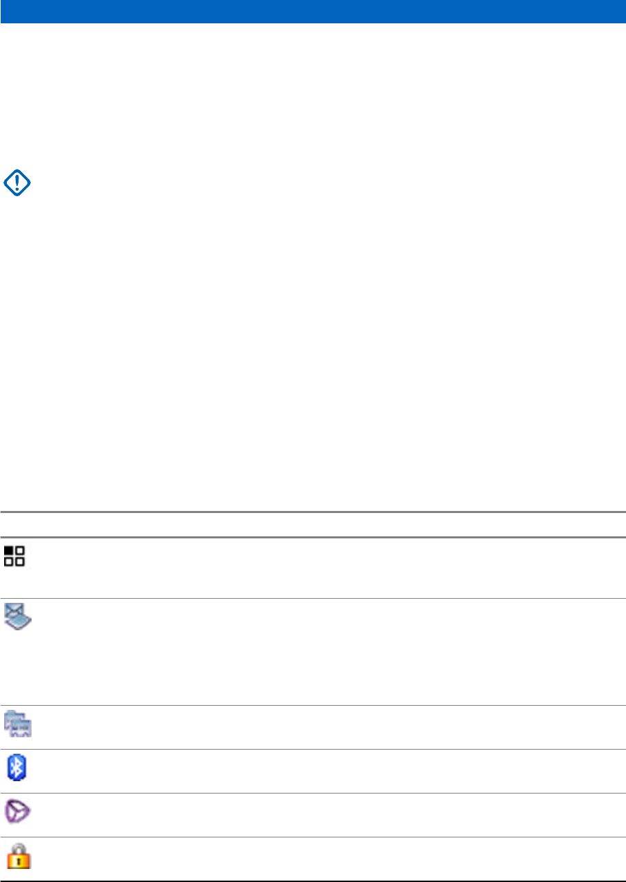
Main Menu
This chapter contains information on items in the main menu.
You can enter the menu items during a call. If not programmed otherwise by your service provider the
radio exits the menu, when a new call starts.
IMPORTANT: Some menu items are model-specific and may not be activated or available on
your radio.
4.1
Scrolling through the Menu
Procedure:
1From the home screen, press the Menu key.
2Scroll to the required item by pressing Navigation keys. Press the Soft key assigned as Select
or Right Navigation key to select.
If the menu item contains a further set of menu items, repeat step 2.
4.2
Menu Icons
The following icons make it easy to identify the menu items at first glance.
Table 12: Menu Icons
Menu Icon Description
Main Menu Items/Context Sensitive Menu
It is assigned to Menu when the main menu items / context-sensitive menu
are active.
Messages
Send status messages.
Send text messages (free text or according to user defined or predefined
templates).
Received messages in Inbox.
Contacts
Add, search, edit, or erase entries in the contact list.
Bluetooth
Allows you to manage Bluetooth settings.
Browser
Starts the WAP browser.
Security
Lets you turn on/off and verify security features, and change passwords.
MN001488A01-BF (en-US)
Main Menu
56
DRAFT
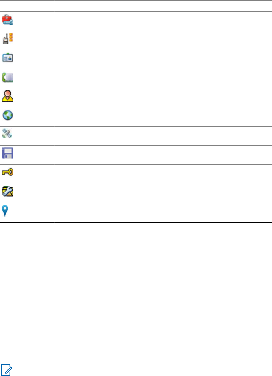
Menu Icon Description
Setup
Allows you to customize your radio.
Group Setup
Contains additional menu items for Scanning Talkgroups features.
My Info
Displays information about your radio and its numbers.
Recent Calls
Contains a list of recent calls.
RUI
Allows you to log in and log out of the radio.
Networks
Allows you to select a network.
Location
Displays location of your radio.
Packet Data
Allows you to send data from your radio to other devices.
Crypto Menu
Allows you to manage SIM Card End-to-End Encryption.
Services
Allows you to manage Broadcast, Assistance, and Disaster Calls.
Indoor Location
Allows you to enable or disable Indoor Location.
4.3
Messages
This feature allows you to send and receive text messages. A message can contain up to 1000
characters, depending on your service provider settings.
Pressing the PTT button when a message is highlighted can cause one of the following actions,
depending on your service provider settings:
• The radio ignores the PTT button request.
• The radio starts a Private Call with the message sender.
• The radio starts a Group Call on a currently selected talkgroup.
See Writing Text on page 129 for details on writing a text message.
4.3.1
New Message
This menu item allows you to create a new message.
NOTICE: While editing a text, Status Icons change their appearance and only four of them are
displayed: Tower, Signal Strength, Emergency, and Battery.
MN001488A01-BF (en-US)
Main Menu
57
DRAFT

The text.|
Send Delete
4.3.1.1
Sending Messages to Private/Phone
Procedure:
1From the home screen, press the Menu key.
2Select Messages → New Message.
3Enter your message and press Send.
4If needed, select Private/Phone.
5Enter recipient number or press abc to choose it from your contacts.
NOTICE:
For Private target selection, you can enter either Individual Short Subscriber Identity
(ISSI), Individual TETRA Subscriber Identity (ITSI), or Group Short Subscriber Identity
(GSSI) of the recipient.
ISSI/ITSI – a unique, individual ID assigned for each radio.
GSSI – in Dimetra called Group ID or Talkgroup ID.
6Press Send, or Send key, or the PTT button.
4.3.1.2
Sending Messages to Groups
Procedure:
1From the home screen, press the Menu key.
2Select Messages → New Message.
3Type your message and press Send.
4If needed, select Group.
5Select a group to send the message.
4.3.1.3
Sending Store and Forward Messages
Prerequisites: Your service provider enables the Store and Forward feature.
Procedure:
1From the home screen, press the Menu key.
2Select Messages → New Message.
3Press Menu key and select Message Setup → On/Offline users.
4Enter your message and press Send.
5If asked for the Target selection, select one of the following:
MN001488A01-BF (en-US)
Main Menu
58
DRAFT

•Private – enter the private number or press abc to choose the destination number from the
contact list.
•Phone – enter the phone number or press abc to choose the destination number from the
contact list.
NOTICE: Your service provider can enable to send a Store and Forward message to a
talkgroup.
6Select Send, or press Send key or PTT button.
4.3.1.4
Delivery Report
Delivery Report is an acknowledgment that the radio can request upon sending a message to an
individual recipient. You can define what type of Delivery Report your radio requests, or turn on/off this
feature.
If the Delivery Report is received shortly after the message was sent, the radio:
•Displays a pop-up with one of the following messages:
-Message Sent – if no Delivery Report is requested (and when a Store and Forward message
has been received at the Store and Forward server).
-Message Delivered – if the Delivery Report is requested and the message has been
received by the target radio.
-Message Read – if the Consumed Delivery Report is requested and the message is opened on
the target radio.
-Message Failed – if the Delivery Report is requested and the message has not been received
by the target radio within a defined time period.
• Saves the Delivery Report in Outbox along with a copy of the message.
If the Delivery Report is received after a longer period of time, the radio:
• Saves the Delivery Report in Outbox along with a copy of the message.
• If Delivery Report Notifications functionality is configured by your service provider, the radio also:
- Temporarily saves a Delivery Report message in Inbox. The notification disappears after it is
read.
- Displays New Message icon.
- Displays New Delivery Status notification screen (if possible).
4.3.1.4.1
Viewing Delivery Reports
Procedure:
1From the home screen, press the Menu key.
2Select Messages → Inbox.
3Find a required message and select Read.
4Press Menu key.
5Select Delivery Status.
MN001488A01-BF (en-US)
Main Menu
59
DRAFT

4.3.1.4.2
Configuring Delivery Reports
Prerequisites: Your service provider enabled the delivery report configuration.
Procedure:
1From the home screen, press the Menu key.
2Select Messages → New Message.
3Press Menu key and select Delivery Report.
4Select one of the following:
•None – the radio does not request any delivery report.
•Received – the radio requests reports on your messages that were received.
•Consumed – the radio requests reports on your messages that were read.
•Both – the radio requests reports on your messages that were received and read.
4.3.2
Inbox
The Inbox folder contains up to 100 new or old incoming messages, depending on the length of the
messages.
Table 13: Inbox Icons
Icon Description
Unread (New) Message
Read (Old) Message
Unread (New) Protected Message
Read (Old) Protected Message
Message Protected
Sender Information in Message View – name or number
Time and Date Stamp in Message View – arrival time and date
Delivery Status Received – delivery status for Store and Forward messages
Messages sub-menu indicates the number of the messages. If the indication is for example 2/4, it
means that two unread and four read messages are in the Inbox.
MN001488A01-BF (en-US)
Main Menu
60
DRAFT

4.3.2.1
Entering the Inbox
Procedure:
1From the home screen, press the Menu key.
2Select Messages → Inbox.
NOTICE: The status (if any) of the list is displayed for a few seconds:
•No New or Old Messages – The screen returns to the previous display within a
few seconds.
•Inbox Full – Select OK.
4.3.2.2
Receiving New Messages
Prerequisites: Your radio displays a New Message icon, an animation, and plays a New Mail
Received tone.
Procedure:
Select one of the following:
•Read – opens the entire message.
•Back – dismisses the message. You can access the message later from the Inbox.
4.3.2.3
Using Submenus in the Inbox and the Outbox
Procedure:
1From the home screen, press the Menu key.
2Select Messages → Inbox or Outbox.
3Highlight the required message and press Menu key.
4Do one of the following:
•Store – Saves a message as a template. Change the default template name and press OK.
•Delete – Deletes the selected message. Press Yes to confirm.
•Delete All – Deletes all the messages in the Inbox or Outbox. Press Yes to confirm.
•Reply (only for Inbox) – Invokes the edit screen with the old message as default text and the
message originator as a recipient. After editing, press Send, the PTT button, or the Send key
to send.
•Resend (only for Outbox) – Invokes the edit screen with previously entered text with the
same recipient. After editing, press Send, the PTT button, or the Send key to send.
•Forward – Invokes the edit screen with the old message to send it to a different participant.
After editing, press Send, the PTT button, or Send key to send.
•Refresh – Re-orders the message list and displays the new messages.
•Delivery Status (only for Outbox) – Shows the date and time of the message when it is
sent, delivered, read, and expired; was not delivered, expired was not read, or failed
unknown.
•Protect – Protects the message from being deleted or overwritten.
•Unprotect – Remove the protection of the message.
MN001488A01-BF (en-US)
Main Menu
61
DRAFT

Message protection functionality is enabled in the Inbox and Call Out Inbox. Users can only
delete unprotected messages.
4.3.2.4
Embedded Number
This feature allows you to call a number from a message or to start a group call with the message
sender talkgroup.
4.3.2.5
Storing Numbers from Messages
Prerequisites: Embedded Number feature is enabled by your service provider.
When and where to use: You can save the number of the sender or embedded number from the
message to a new or existing contact.
Procedure:
1From the home screen, press the Menu key.
2Select Messages → Inbox.
3Highlight the required message and select Read.
4Press the PTT button.
5Radio displays a list of the numbers (including the senders number).
6Highlight the required number and press Store.
7Highlight required contact and press View.
NOTICE: To store a number for a new contact, select [New Contact] and fill out the
required fields. Press Done to save it.
8Select Edit.
9Choose the Type of the new number and press Done.
4.3.2.6
Calling Numbers in Messages
Prerequisites: Embedded Number feature is enabled by your service provider.
When and where to use: You can return a voice call to the sender of a message or to any number
that is embedded in the message text.
Procedure:
1From the home screen, press the Menu key.
2Select Messages → Inbox.
3Highlight the required message and select Read.
4Press the PTT button.
5Radio displays a list of the numbers (including the senders number).
6To call, highlight to the required number and press the PTT button or the Send key.
7Select Ctype to choose the type of call (Private, Phone, or PABX).
8Press the PTT button or the Send key.
MN001488A01-BF (en-US)
Main Menu
62
DRAFT

4.3.2.7
Making Group Calls on the Talkgroup of the Message Sender
Prerequisites: Embedded Number feature is enabled by your service provider.
Procedure:
1From the home screen, press the Menu key.
2Select Messages → Inbox.
3Highlight the required message and press the PTT button.
4.3.2.8
Immediate Message
NOTICE: This feature is a paid feature.
When the new immediate message is received, radio plays the New Mail Received tone and displays
the content overlapping your previous screen. All immediate messages are stored in the Inbox. If the
radio is in PIN Lock state, immediate message is displayed after correct PIN is entered.
The message stays on the screen until you press the End/Home key.
4.3.3
Outbox
Outbox stores up to 100 sent messages arranged chronologically with the last sent message at the top
of the list.
Table 14: Outbox Icons
Icon Description
Delivery in Progress
Delivery Accomplished
Delivery Failed
Successful Outgoing Message
Failed Outgoing Message
Protected Message Delivery in Progress
Protected Message Delivery Accomplished
Protected Message Delivery Failed
Successful Outgoing Protected Message
Failed Outgoing Protected Message
MN001488A01-BF (en-US)
Main Menu
63
DRAFT

4.3.4
Call-Out (CO) Box
CO Box contains incoming and outgoing Call-Out messages. Clicking Select on a Call-Out message
headline displays more detailed information on the item.
When the radio is in normal mode, you are able to browse through all messages in the CO Box.
However, if the radio is in the Call-Out mode, you can only browse through the information regarding
the currently ongoing Call-Out message.
4.3.4.1
Call-Out Icons
Table 15: Call-Out Icons
Icon Description
Read (Old) Call-Out Message in Inbox
Unread (New) Call-Out Message in Inbox
Read (Old) Protected Call-Out Message in Inbox
Unread (New) Protected Call-Out Message in Inbox
Read (Old) Call-Out Message in Outbox
Read (Old) Protected Call-Out Message in Outbox
4.3.5
Wireless Application Protocol (WAP) Box
Each WAP Push message can be loaded immediately or stored as a message in WAP Box. To access
the WAP Box, press Menu → Messages → WAP Box. All the WAP Push messages are passed to
the browser.
4.3.6
Templates
Templates box stores user-defined message templates. Each of the Inbox and Outbox message can
be stored as a template. Each template name and text can be edited afterwards.
4.3.6.1
Sending User-Defined Templates
Procedure:
1From the home screen, press the Menu key.
2Select Messages → Templates.
3Highlight the required template name and press Send.
4Do one of the following:
MN001488A01-BF (en-US)
Main Menu
64
DRAFT

• Enter the number or press abc to select the name from your contact list. Press Send.
•Select required talkgroup from the TalkGroup List.
4.3.6.2
Managing User-Defined Templates
Procedure:
1From the home screen, press the Menu key.
2Select Messages → Templates.
3Highlight the required template and press Menu.
4Select one of the following:
•View – Displays template text.
•Delete – Deletes the template.
•Edit Text – Opens edit screen with the template text. Edit the text and press Menu. Select
Save Changes to save edited template, or Store to save the edited template as a new one.
•Edit Name – Opens edit screen with the template name. Press Ok to save the template.
4.3.7
Predefined Templates
Predefined message templates are programmed into your radio. You are allowed to perform limited
edit operations of the predefined template. You can send it, but you are not able to store the edited
template or erase it from the predefined template list.
4.3.7.1
Viewing Predefined Templates
Procedure:
1From the home screen, press the Menu key.
2Select Messages → Predefined.
3Highlight the required template and press Menu key.
4Select View.
4.3.7.2
Sending Predefined Templates
Procedure:
1From the home screen, press the Menu key.
2Select Messages → Predefined.
3Highlight the required template and press Send, the PTT button, or the Send key.
NOTICE: You can edit the predefined template before you send it. Press the Menu key
and select Edit. Edit screen opens with the template text. You are only allowed to
replace the existing text.
MN001488A01-BF (en-US)
Main Menu
65
DRAFT

4.3.8
Status Messages
The radio allows you to send two types of status messages: statuses and targeted statuses. Your
service provider determines which type is enabled on the radio.
Statuses can be sent either to a selected talkgroup or to a private number programmed by your service
provider. Targeted statuses can be sent to any talkgroup defined for the radio or to any private number
(from the contact list or entered manually).
4.3.8.1
Viewing a Status Message Number
Procedure:
1From the home screen, press the Menu key.
2Select Messages → Send Status.
3Press the Menu key and select View.
4.3.8.2
Sending Status Messages
This procedure allows you to send status messages to either a selected talkgroup or a programmed
private number. Only one option can be enabled at a time.
Prerequisites:
• If sending statuses to talkgroups is enabled: switch to the talkgroup to which you want to send a
status message.
• If sending statuses to private numbers is enabled: no action is needed, the private number is set up
by your service provider
Procedure:
1From the home screen, press the Menu key.
2Select Messages → Send Status.
3Highlight the required status message and press Select, the PTT button, or the Send key.
4.3.8.3
Targeted Status Messages
This feature enables sending status messages to user selectable addresses. By default, targeted
status messages can be sent to private or talkgroup addresses. Your service provider may restrict valid
addresses to numbers stored in Contacts.
NOTICE: This feature is not supported on Dimetra networks.
4.3.8.3.1
Sending Targeted Status Messages
Procedure:
1From the home screen, press the Menu key.
2Select Messages → Send Status.
3Highlight the required status message and press Select, the PTT button, or the Send key.
MN001488A01-BF (en-US)
Main Menu
66
DRAFT

4Do one of the following:
•Enter the number or press abc to select the name from your contact list. Press Send.
• Select required talkgroup from the TalkGroup List.
The display shows one of the following delivery reports:
•Status Sent.
•Status Failed.
4.3.9
Sending an RMS Status
Prerequisites: This feature is only available when enabled by your service provider. See Radio
Messaging System (RMS) on page 126 for details.
Procedure:
1Do one of the following:
• From the home screen, press Menu → Messages → Send RMS/FMS.
• Press and hold the One Touch Button configured to display the Send RMS/FMS menu.
NOTICE: The navigation through the radio menu is only available if your service provider
enabled the Send RMS/FMS menu item. However, your service provider can configure a
One Touch Button to display the Send RMS/FMS menu even if the navigation is not
possible.
If the Send RMS/FMS menu item is disabled, and no One Touch Button is configured to
display the Send RMS/FMS menu, then the radio can only receive RMS messages but
cannot send them.
2Scroll to the required RMS status.
4.3.10
Additional Address
The Additional Address feature allows the radio to send RMS messages, and Local Information
Protocol (LIP) reports to additionally defined recipients.
The default addresses where the radio sends RMS messages and LIP reports are defined by your
service provider. If an Additional Address is selected and enabled, RMS messages and LIP reports are
also sent to the recipient defined in the Additional Address.
You can create, edit, and delete Additional Addresses using the radio menu. If an Additional Address is
configured by your service provider, the service provider can disable edition and deletion of the
address using the radio menu.
You can define up to 30 Additional Addresses.
4.3.10.1
Enabling or Disabling Additional Address
Procedure:
1From the home screen, press the Menu key.
2Select Messages → Additional Address → Enable.
3Select one of the following:
•On – to activate the feature
MN001488A01-BF (en-US)
Main Menu
67
DRAFT
•Off – to deactivate the feature
4.3.10.2
Selecting Additional Address
Procedure:
1From the home screen, press the Menu key.
2Select Messages → Additional Address → Select Address.
Select Address display appears with an available list of aliases.
3Scroll through the list to highlight your alias and press Select.
4.3.10.3
Viewing Additional Address
Procedure:
1From the home screen, press the Menu key.
2Select Messages → Additional Address → Select Address.
3Scroll to select the alias of the Additional Address you wish view.
4Press the Menu key.
5Select one of the following:
•Edit (for User Defined Additional Address alias)
•View (for Pre-defined Additional Address alias)
The display shows the Alias, the ISSI/ITSI/GSSI and the Status of the address (Pre-Defined or User
Definded).
4.3.10.4
Entering New Additional Address
Procedure:
1From the home screen, press the Menu key.
2Select Messages → Additional Address → Select Address.
3Select [New Address]
4Press Change key.
5Enter new values of the Alias and ISSI/ITSI/GSSI fields, press Done key.
The new alias appears in the list of available aliases. There is no possibility to have two Additional
Address items with the same Additional Address Alias.
4.3.10.5
Editing Additional Address
Prerequisites: Editing Additional Address is allowed only for User-Defined positions. Pre-Defined
positions can only be Selected or Viewed.
Procedure:
1From the home screen, press the Menu key.
2Select Messages → Additional Address → Select Address.
MN001488A01-BF (en-US)
Main Menu
68
DRAFT

3Highlight the alias.
4Press Menu key.
5Select Edit.
6Press Change.
7Enter new values of the Alias and ISSI/ITSI/GSSI fields, press Done key.
The changed alias appears in the list of available aliases. There is no possibility to have two Additional
Address items with the same Additional Address Alias.
4.3.10.6
Deleting Additional Address
Prerequisites: Deleting Additional Address is allowed only for User-Defined positions. Pre-Defined
positions can only be Selected and Viewed.
Procedure:
1From the home screen, press the Menu key.
2Select Messages → Additional Address → Select Address.
3Scroll to select the alias of the Additional Address you wish delete.
4Press the Menu key.
5Select Delete and confirm deletion by the OK key.
4.3.11
Call-Out Availability
This menu item enables or disables the Call-Out availability.
NOTICE: This feature is only available when enabled by your service provider.
4.3.11.1
Setting Call-Out Availability
Procedure:
1From the home screen, press the Menu key.
2Select Messages → Call-Out Availability.
3Select one of the following:
•Available
•Not available
4.4
Contacts
This menu stores all your contact numbers. Each entry requires the following information:
•Name – if you store more than one number to one contact, this entry is required.
MN001488A01-BF (en-US)
Main Menu
69
DRAFT
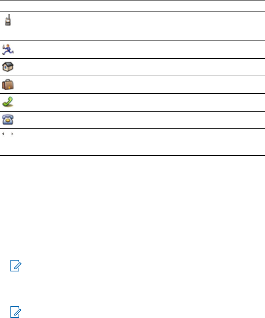
•Type – each contact must be assigned to one of the following types:
Table 16: Contact Types
Contact Icon Description
Private
Cannot have a speed dial number.
Mobile
Home
Work
PABX
Other
Pickers
Indicate more than one number in a contact.
•# (number) – each contacts entry must contain a number.
•Speed # – accept the default Speed Dial number or change it.
4.4.1
Creating Contacts
Procedure:
1From the home screen, press Contcs.
2Select [New Contact].
3Highlight Name and press Change. Enter the name of your contact and press Ok.
4Highlight Type and press Change. Select the required type of your contact.
NOTICE: You can use the Left and Right Navigation keys to select the type of your
contact from the Contact Details screen.
5Highlight # (number) and press Change. Enter the number of your contact and press Ok.
6If needed, highlight Speed # and press Change. Enter the speed dial number (1– 1000) of your
contact and press OK.
NOTICE: If the entered number exist, the radio displays Overwrite? message. Press
Yes to confirm, or No to enter the speed dial number again.
7Press Done.
You have create a contact with one number. To add additional number repeat steps step 4 – step 6.
MN001488A01-BF (en-US)
Main Menu
70
DRAFT

4.4.2
Editing Contacts
Procedure:
1From the home screen, press Contcs.
2Highlight the contact you want to edit.
3Press the Menu key.
4Press Edit.
5Highlight one of the following entries and press Change to edit:
•Name
•Type
•# (number)
•Speed #
6Press Done.
4.4.3
Deleting Numbers
Procedure:
1From the home screen, press Contcs.
2Select a contact you want to edit.
3Use Left or Right Navigation keys to choose the required number.
4Press Menu.
5Select Delete number.
NOTICE: If an entry contains only one number, deleting the number deletes the entry.
6Press Yes.
4.4.4
Deleting Contacts
Procedure:
1From the home screen, press Contcs.
2Highlight a contact you want to delete.
3Press the Menu key.
4Select Delete contact.
5Select Yes.
MN001488A01-BF (en-US)
Main Menu
71
DRAFT
4.4.5
Checking Capacity
When and where to use: To see how many numbers are stored in the radio.
Procedure:
1From the home screen, press Contcs.
2Press the Menu key.
3Select Capacity.
4Select one of the following:
•Private
•Phone/PABX
•Contact
4.4.6
Dialing through the Contact List
Procedure:
1From the home screen, press Contcs.
2To highlight the required contact, use Up and Down Navigation keys, or enter up to 12
characters of the contact name.
3If the contact has more than one number, use Left and Right Navigation keys to select the
required number.
4To initiate a simplex call, press the PTT button with a Private number. Otherwise use the Send
key to initiate a duplex call.
4.5
Bluetooth
This menu activates the Bluetooth feature. See Bluetooth on page 116 for details.
4.5.1
Bluetooth Settings
Bluetooth Settings allows you to configure radio settings related to Bluetooth activity.
4.5.1.1
Configuring Bluetooth Settings
Procedure:
1From the home screen, press the Menu key.
2Select Bluetooth → Settings.
3Select one of the following:
•Bluetooth – enables/disables Bluetooth.
•Name – edits the name of your radio. This name is visible to other remote devices.
•Indications – enables/disables audible indications played by the radio during Bluetooth
actions.
MN001488A01-BF (en-US)
Main Menu
72
DRAFT

•Audio – determines the audio connection mode for headsets. You can select one of the
following:
•Power Optimized – the Bluetooth audio link is released when there is no active call. This
option increases the battery life time, but causes a delay in the call setup time for group
calls. This delay may result in lost audio on some headsets.
•GC Optimized – the Bluetooth audio link is kept open all the time. This option ensures
that audio during group calls is heard without any delay and the audio link is never lost,
but shortens the battery life time.
NOTICE: This setting does not affect the Motorola Solutions headset with PTT
(NNTN8143_ or NNTN8191_) as it is always in the GC Optimized mode.
4.5.2
Enabling and Disabling Bluetooth
Procedure:
1From the home screen, press the Menu key.
2Select Bluetooth → Bluetooth: On / Bluetooth: Off.
3Select On to enable, or Off to disable Bluetooth.
When Bluetooth is enabled, the Bluetooth icon appears in the status icon area on the display.
However, the Bluetooth icon may not be visible at times, due to other icons with higher priority
being displayed in the same icon slot.
NOTICE:
Your service provider may configure the radio to automatically disable Bluetooth after
entering the home mode. The home mode is a state in which all the following conditions
are met: the radio is not in the Discoverable Mode, all active remote devices are
disconnected (including file transfer), and scanning for remote devices is not performed.
4.5.3
Pairing Bluetooth Devices with Your Radio
Pairing is a process that creates a link between two Bluetooth-enabled devices. Once paired, devices
remember each other and every subsequent connection between them is authenticated automatically.
When and where to use: To scan for available Bluetooth-enabled devices and to connect with them.
Procedure:
1From the home screen, press the Menu key.
2Select Bluetooth → Add Device. Ensure that the device you want to connect with is in pairing
mode.
The radio lists available devices that can be paired with your radio.
3Highlight the required device and select Connect.
NOTICE: Press accessory PTT button to improve the connection between the accessory
and radio.
4If needed, enter a PIN code or a passkey.
NOTICE: If you enter an incorrect PIN code and the subsequent paring attempts take too
long or result in an error message, power the Bluetooth device off and on. The radio
accepts 3 logging attempts.
MN001488A01-BF (en-US)
Main Menu
73
DRAFT

4.5.4
Devices
This menu item lists all devices paired with your radio and allows you to perform the following
operations:
•Connect a device.
• View and change device details.
• Disconnect a device.
• Delete a device.
4.5.4.1
Connecting or Disconnecting Devices
Prerequisites: Only pre-approved sensor devices can be used. The service provider is responsible for
configuring the radio to work with specific devices. See Add Bluetooth Devices on page 117.
Procedure:
1From the home screen, press the Menu key.
2Select Bluetooth → Devices.
3Highlight the required device and press Menu/OK. Select Connect/Disconnect.
NOTICE:
Depending on languages installed on the radio, some characters in names of devices
might not be displayed properly.
Radio-initiated automatic reconnection with several remote Bluetooth devices at the
same time cannot be guaranteed to be successful in 100%, due to the fundamental
nature of Bluetooth. In case the reconnection fails after a power cycle (power off and
power on of the radio), reconnect the device manually.
4.5.4.2
Managing Devices
Procedure:
1From the home screen, press the Menu key.
2Select Bluetooth → Devices.
3Highlight the required device and press the Menu key.
•Name – shows the name of the device (up to 32 characters long). The name is editable only
if it has not been pre-set by the service provider.
•Type – displays the device type. This menu item cannot be configured.
•Access – defines how the radio behaves during a reconnection attempt after losing
connection to this device:
•Automatic – the radio connects with the device automatically.
NOTICE: On some headsets, you may have to press the "Call" button to trigger
reconnection.
•Ask – the radio asks you for confirmation before connecting with the device.
•Manual – the radio connects with the device manually.
•Never – the radio never connects with the device.
MN001488A01-BF (en-US)
Main Menu
74
DRAFT

•Delete – deletes the device from the paired devices lists.
4.5.5
Disconnecting All Devices
When and where to use: To disconnect all remote devices connected to your radio.
Procedure:
1From the home screen, press the Menu key.
2Select Bluetooth → Disconnect All.
All devices are disconnected.
NOTICE: To disconnect only one device, from the home screen, select Menu → Bluetooth →
Devices, highlight the required device, and press Disconnect.
4.5.6
Setting Indoor Location
When and where to use: Indoor Location is used to track radio location while indoors. Your radio
receives beacon information from a number of dedicated beacons within range of the radio when
Indoor Location is activated. The radio then send the information within a LIP message to the SwMI,
and a mapping application will decode the information to calculate the radio location.
NOTICE: Your service provider can enable this feature.
Procedure:
1From the home screen, press the Menu key.
2Select Bluetooth → Indoor Location.
3Select Change.
4Select On or Off to activate or deactivate Indoor Location.
Your radio is now able to detect Bluetooth location beacons when activated.
NOTICE: The use of the Indoor Location feature may have a negligible impact on other
Bluetooth functionality of your radio.
4.5.6.1
Viewing Detected Beacon
Prerequisites: Turn on Indoor Location. If Indoor Location is turned off, the screen displays Service
Restricted.
Procedure:
1From the home screen, press the Menu key.
2Select Bluetooth → Indoor Location.
3Select Beacons Found.
4Select desired beacon.
The screen displays details of the beacon.
MN001488A01-BF (en-US)
Main Menu
75
DRAFT

4.5.7
Connecting Firearms Devices
Prerequisites: Only pre-approved firearms devices can be used. The service provider is responsible
for configuring the radio to work with specific devices. See Add Bluetooth Devices on page 117.
When and where to use: To select a firearm sensor device for Bluetooth connection.
Procedure:
1From the home screen, press the Menu key.
2Select Bluetooth → Firearms.
3Highlight your firearm sensor device and press Connect.
NOTICE:
Activation code must be sent to the device by third-party application.
Radio-initiated automatic reconnection with several remote Bluetooth devices at the
same time cannot be guaranteed to be successful in 100%, due to the fundamental
nature of Bluetooth. In case the reconnection fails after a power cycle (power off and
power on of the radio), reconnect the device manually.
The radio is now able to notify the dispatcher when the status of the firearm device changes. If
configured, the location (using GNSS) of the radio is reported as well. Once a firearm sensor
device is connected, it can be managed from the Devices menu.
4To disconnect a firearm sensor device, go to the Devices menu and follow the normal device
management procedure.
4.6
Browser
This menu item activates a WAP browser that allows you to browse the Internet from your radio. See
Wireless Application Protocol (WAP) on page 130.
4.7
Man Down
NOTICE: This feature is a paid feature.
Man Down alerts when no movement occurs for a set time or the radio stays at an angle of tilt below a
defined value. The radio alerts you when:
•Its tilt exceeds a predefined angle value.
• No movement is detected in a predefined time interval.
In case any of the conditions are met, the radio alerts you with a Man Down pre-alert. If you do not
disable the pre-alert condition, the radio switches to the Emergency Operation.
For easier localization of the radio, visual and audible indications are started until they are deactivated.
If the Emergency Hot Microphone is on, the additional audio indication is not played.
To exit Man Down, exit the Emergency Mode by pressing and holding the Exit Soft key, or press the
PTT button.
MN001488A01-BF (en-US)
Main Menu
76
DRAFT

4.7.1
Setting Man Down
Procedure:
1From the home screen, press the Menu key.
2Select Man Down.
3Select one of the following:
•On – Activates the feature.
•Off – Deactivates the feature.
4.8
Security
This sub-menu stores all your security settings.
4.8.1
PIN Protect
This feature allows you to enable PIN code authentication at the next power on. This code protects
your radio against unauthorized use.
If you are unable to unlock the radio, you can only send or receive Emergency Calls and adjust the
volume level with the Volume Knob.
NOTICE: If the radio uses a SIM Card PIN code and you are unable to unlock the radio, you
cannot take any action.
4.8.1.1
Protecting the Radio with a PIN Code
Procedure:
1From the home screen, press Menu → Security → PIN Protect.
2Select On.
3Enter 4-digit PIN code. By default it is 0000 (four zeros).
NOTICE: To increase security, set your own PIN code.
Postrequisites: Each time you turn on the terminal, PIN code is required.
4.8.1.2
Changing PIN Codes
Procedure:
1From the home screen, press the Menu key.
2Select Security → Change Code.
3Radio prompts for the Old Code. Enter currently used 4-digit security code (default setting is
0000).
4If the entered code matches the old code, radio prompts for the new code twice.
Your radio displays Code Accepted.
MN001488A01-BF (en-US)
Main Menu
77
DRAFT

4.8.2
Setting Keypad Lock
The keypad lock/unlock can be invoked from the radio menu, or by using a predefined menu shortcut.
By default, the Power and Emergency buttons are always operative when the keypad is locked.
Procedure:
Do one of the following:
•Press Menu, and then Left Navigation key.
• To lock, select MENU → Security → Keylock Setup → Lock Keypad. Use the predefined
menu shortcut to unlock.
4.8.2.1
Keypad Lock Notification
When the keypad is locked, your service provider can configure one of the following instructions:
• None – no notification is displayed.
• Notification Only – Keys Locked is displayed.
• Notification and Instruction – Press Menu + Left to lock/unlock keypad is displayed.
4.8.2.2
Setting Automatic Keylock Delay
Procedure:
1From the home screen, press the Menu key.
2Select Security → Keylock Setup → Delay.
3Use Up and Down Navigation keys to change the minutes and press Done.
4.8.2.3
Setting Keylock on Startup
Procedure:
1From the home screen, press the Menu key.
2Select Security → Keylock Setup → Start Locked.
3Select On/Off.
4.8.3
Air Encryption
NOTICE: This feature is a paid feature.
Air Encryption is a feature that enables encryption of entire communication between the radio and
infrastructure, which results in increased security of calls, messages, and data.
If configured by your service provider, the radio plays a sound and displays Call & Data Not
Encrypted when encryption is on and you receive a clear call (unencrypted). This feature provides
service confidentiality between you and the system.
MN001488A01-BF (en-US)
Main Menu
78
DRAFT

In the TMO Mode, when Air Encryption is enabled on your radio but cannot be supported due to an
infrastructure failure, the following icon appears on the display: . When encryption is not available in
the DMO Mode, the radio displays: .
This menu item allows you only to view air encryption state.
4.8.3.1
Viewing Air Encryption State
Procedure:
1From the home screen, press the Menu key.
2Select Security → AirEncrypt.
Your radio displays:
•Air Encryption Is Off.
•Air Encryption Is On.
4.8.3.2
Deleting User Keys
Prerequisites: Ensure that the user key deletion is enabled in the codeplug.
Procedure:
1Press Side Button 1 → Side Button 1 → Side Button 1 → Side Button 2 → Side Button 2 →
Side Button 2.
IMPORTANT: The key deletion takes up to 30 seconds. During the period, the battery
must not be removed. Removing the battery during that period may lead to radio
malfunction.
Encryption and/or Authentication keys are deleted. The radio enters Temporary Disable state and the
service provider must manually restore it.
4.8.4
K Validity
Key (K) is a secret key the infrastructure uses to authenticate the radio in the system. It is part of the
authentication that provides service confidentiality between your radio and the system.
4.8.4.1
Verifying K Validity
Procedure:
1From the home screen, press the Menu key.
2Select Security → K Validity.
3Your radio displays:
•K is Valid – the infrastructure can authenticate your radio.
•K is Invalid – the infrastructure is unable to authenticate your radio. Please call your
service provider to restore the key to your radio.
MN001488A01-BF (en-US)
Main Menu
79
DRAFT
4.8.5
SCK (Air Interface Encryption Class 2)
Static Cipher Key (SCK) is a secret key used for the Air Interface Encryption Class 2. It may be used to
encrypt calls and data in TMO and DMO. The SCK air interface encryption provides service
confidentiality between radios and infrastructure when in TMO, and between radios when in DMO. A
radio is capable of being loaded with up to 32 SCKs. Specific keys are used for encrypting the air
interface.
Any mismatch between radios and/or infrastructure impacts communication – only those using the
same key as the transmitting party are able to decode and hear the communication.
4.8.5.1
TMO SCK
Your service provider can enable SCKs in TMO. The SCKs used in TMO are called TMSCKs.
4.8.5.1.1
Verifying TMSCK Validity
When and where to use: To ensure that the TMSCKs in the radio are valid and can be used for the
air interface encryption.
Procedure:
1From the home screen, press the Menu key.
2Select Security → TMSCK Validity.
3The radio displays:
•TMSCK is Valid – the radio can work encrypted in TMO.
•TMSCK is Invalid – the radio cannot work encrypted in TMO. Please contact your
service provider to restore SCKs to your radio.
4.8.5.2
DMO SCK
Your service provider can enable SCKs in DMO. The SCKs used in DMO are called DMSCKs.
4.8.5.2.1
Verifying DMSCK Validity
When and where to use: To ensure that the DMSCKs in the radio are valid and can be used for the
air interface encryption.
Procedure:
1From the home screen, press the Menu key.
2Select Security → DMSCK Validity.
3The radio displays:
•DMSCK is Valid – the radio can work encrypted in DMO.
•DMSCK is Invalid – the radio cannot work encrypted in DMO. Please contact your
service provider to restore SCKs to your radio.
MN001488A01-BF (en-US)
Main Menu
80
DRAFT

4.8.5.3
Changing DMO SCK
IMPORTANT: Changing this setting may cause radios not to operate correctly.
Procedure:
1From the home screen, press the Menu key.
2Select Security → DMO SCK.
3Press Next.
4Radio displays Change to version .
5Select one of the following:
•Yes – to change the key. Your radio displays Key version changed.
•No – to leave the key. Your radio displays Code Not Changed.
4.8.6
Covert Mode
This feature enables you to completely shut down all visible and audible alerts and notifications making
the radio unnoticeable even in a silent and dark environment.
When your radio is in the Covert Mode, you cannot enter the following menu items of the Setup menu.
•Set Volume
•Tones
•Backlight (in Display menu item)
When the Covert Mode is turned on:
• All tones are set to Off (corresponding to All Tones menu entry).
• Group audio is set to Spkr Cntrl (corresponding to Audio Toggle menu entry).
• The private speaker is set to Off (this setting causes all the calls are routed through the earpiece).
• Backlight is set to Disabled (corresponding to Backlight menu entry).
• The LED indicator is switched off.
The radio powers up in the mode set before turning off. Thus if the Covert Mode was set before turning
off, the radio turns on in the Covert Mode .
When the Covert Mode is turned off, all the changed settings are reverted to the previous state.
This feature can be used as the One-Touch Button.
4.8.6.1
Activating Covert Mode
Procedure:
1From the home screen, press the Menu key.
2Select Security → Covert Mode.
3Select one of the following:
•On – all tones are set to off, and the backlight and the LED are disabled immediately. The
group audio is routed to the earpiece. The radio displays Covert Mode On.
MN001488A01-BF (en-US)
Main Menu
81
DRAFT

•Off – all settings for tones, backlight and audio are restored. The radio displays Covert
Mode Off.
4.8.6.2
Setting Vibrate in Covert Mode
Procedure:
1From the home screen, press the Menu key.
2Select Security → Covert Mode → Vibrate.
3Select one of the following:
•On – To restore all vibrations.
•Off – To disable all vibrations.
4.8.7
Remote Control
There are two types of remote control, Short Data Service (SDS) Remote Control and Status Remote
Control.
4.8.7.1
Status Remote Control
Status Remote Control is a feature that provides limited control of the radio, unlike Short Data Service
(SDS) Remote Control.
NOTICE: Only one type of remote control can be active on a radio; either SDS or Status.
The following tasks can be assigned remotely to a radio:
Play loud tone until user interaction
The radio plays a loud tone as in the Man Down feature until you unlock the keypad (if needed) and
press the appropriate soft key labeled Exit. The tone is played through the speaker even if an
accessory is attached.
NOTICE: The tone is not emitted when the radio is in one of the following states:
• In a call
•Temporarily disabled
• Pseudo Off Mode
• Ambience Listening Mode
• Transmit Inhibit Mode (TXI)
• Emergency Mode
• Silent Emergency Mode
• Covert Mode
Send firmware version and TEI
The radio sends back an SDS message with its firmware version and TEI.
NOTICE: If the sending Individual Short Subscriber Identity (ISSI) is not on the Allowed ISSIs
list, the receiving radio ignores the task.
MN001488A01-BF (en-US)
Main Menu
82
DRAFT

4.8.7.2
SDS Remote Control
NOTICE: This feature is a paid feature.
NOTICE: Only one type of remote control can be active on a radio; either SDS or Status.
SDS Remote Control is a feature that enables remote control and configuration of the radio via special
SDS messages. The messages can be sent both in TMO and DMO (including the Repeater Mode) by
any radio capable of controlling other radios. During the execution of the Remote Control messages,
depending on your service provider settings, the radio can play a tone or display an appropriate icon in
the status icon area.
4.8.7.3
Setting Remote Control
This procedure describes how to toggle remote control.
Procedure:
1From the home screen, press the Menu key.
2Select Security → Remote Control.
3Select On to enable, or Off to disable remote control.
4.9
Setup
This sub-menu allows you to change your radio configuration.
4.9.1
Vibrate
This sub-menu allows you to determine if your radio vibrates, or rings, or vibrates and then rings when
receiving a call.
4.9.1.1
Setting Default Vibrate
Procedure:
1From the home screen, press the Menu key.
2Select Setup → Vibrate.
3Select one of the following:
•Vibe then Ring
•Vibe Only
•Ring Only
MN001488A01-BF (en-US)
Main Menu
83
DRAFT

4.9.1.2
Setting Detail Vibrate
Procedure:
1From the home screen, press the Menu key.
2Select Setup → Vibrate → Custom....
3Select one of the following:
•Duplex Calls – Sets the vibrate settings for Phone, PABX, and Duplex Private calls.
•Simplex Calls – Sets the vibrate settings for Simplex Private Calls.
•Group Call – Sets the vibrate settings for Group Calls.
•Mail Rcvd – Sets the vibrate settings for status messages and text messages.
4Select the required setting, and press Select.
NOTICE:
If you choose Group Call, the settings available are:
•Vibe On,
•Vibe Off.
4.9.2
Ring Style
This sub-menu allows you to set the incoming call ring style.
4.9.2.1
Setting Ring Style
Procedure:
1From the home screen, press the Menu key.
2Select Setup → Ring Style.
3Select one of the following:
•Duplex – to set the new ring style to all duplex calls.
•Simplex – to set the new ring style to all simplex calls.
NOTICE: Upon entry into this sub-menu, the display shows the current ring style used.
4Scroll to the desired style and press Select.
NOTICE: New ring style is played immediately for a few seconds. If necessary, adjust the
volume level.
4.9.3
Set Volume
This menu item allows you to adjust the Speaker and Earpiece tone volumes.
MN001488A01-BF (en-US)
Main Menu
84
DRAFT

4.9.3.1
Setting Volume
Procedure:
1From the home screen, press the Menu key.
2Select Setup → Set Volume.
3Select Speaker or Earpiece.
4Select one of the following:
•Voice Vol – sets the volume level for voice.
•Duplex Vol – sets the volume level for duplex ringtones.
•Simplex Vol – sets the volume level for simplex ringtones.
•Keypad Vol – sets the volume level for keypad tones.
•Tones Vol – sets the volume level for alert tones.
•Call-Out Vol – sets the volume level for Call-Out tones (if enabled).
NOTICE: If the display shows only one option Volume, you can adjust all of the above
settings at once. You have the option to change the settings individually when the
Volume Adj. Mode is set to Individual.
5Press Right or Left Navigation key to change the value.
NOTICE: When the battery level is low it is not recommended to attach the 4 Ω speaker
to the radio as it can cause reset or shutdown of the radio.
4.9.4
Language
This sub-menu allows you to change the language of the radio.
4.9.4.1
Setting Language
Prerequisites: The list of available languages is set by service provider.
Procedure:
1From the home screen, press the Menu key.
2Select Setup → Language.
3Select desired language.
4.9.5
Data Setup
This menu item allows you to set up your radio to transmit and receive data from the external device.
To connect your radio accessory connector to the external device, use the PMKN4127 or PMKN4129
cable. The external device must run an application complying with the TETRA standards.
NOTICE:
•Data services are available only in TMO Mode.
• Data services are blocked in TXI Mode.
• When set to Voice Only, the built-in data modem is disabled to conserve battery power.
MN001488A01-BF (en-US)
Main Menu
85
DRAFT
4.9.5.1
Setting Data Function
Procedure:
1From the home screen, press the Menu key.
2Select Setup → Data Setup.
3Select one of the following:
•Voice Only – Your radio receives and transmits voice calls only.
•Data Only – Your radio acts as a modem. It rejects incoming and outgoing voice calls
(except for Emergency Calls), status and text messages.
•Voice & Data – Your radio acts as a modem but voice calls have priority over data calls and
can interrupt them.
4.9.6
Audio
This menu item allows you to adjust your radio audio settings.
4.9.6.1
Audio Profiles
An audio profile is a set of audio parameters, such as the volume of alert tones, that are configured by
your service provider to fit a particular operating environment. For example, the audio parameters can
be adjusted to situations when the radio operates inside a building or on a noisy street.
Your service provider can configure a maximum of five audio profiles.
For a detailed description of a specific audio profile, contact your service provider.
4.9.6.1.1
Setting Audio Profiles
When and where to use: To adjust the audio parameters of the radio in its current operating
environment.
Procedure:
1From the home screen, press the Menu key.
2Select Setup → Audio → Audio Profile.
3Select a required profile.
4.9.6.2
Howling Suppression
The howling suppression is a mode increasing the stability of the acoustic feedback loop. The radio
eliminates howling caused by the feedback loop from the receiving radios to the sending radio in
simplex calls. You can toggle the howling suppression during an active call.
To enable this anti-howling function, you can either use the radio menu or the corresponding One-
Touch Button.
MN001488A01-BF (en-US)
Main Menu
86
DRAFT

4.9.6.2.1
Setting Howling Suppression
Procedure:
1From the home screen, press the Menu key.
2Select Setup → Audio → Howling Suppr..
3Select required setting.
NOTICE: Your service provider can set up the state of the howling suppression on
powering up the radio. Depending on the settings, the radio can either disable the
howling suppression or set the last remembered state.
4.9.6.3
Audio Toggle
You can control audio routing between the speaker and earpiece for any private or group call through
the dedicated Speaker Control key. You can also define through the menu to have all group calls in
high audio or controlled by the Speaker Control key.
4.9.6.3.1
Setting Audio Toggle
Procedure:
1From the home screen, press the Menu key.
2Select Setup → Audio → Audio Toggle.
3Select one of the following:
•Always Loud – The audio sound comes from the speaker (high audio only).
•Spkr Cntrl – The audio goes through the earpiece or the speaker.
4.9.6.4
Volume Adjustment Mode
You can set the volume to Individual or Common. When it is set to Individual, the volume level for
Voice, Duplex, Simplex, Keypad, Tones, and Call-Out can be set per user preferences. When set to
Common, the audio has one setting for all items. The Volume Control Mode is configurable using the
Customer Programming Software (CPS).
NOTICE: When a volume control capable Bluetooth device is connected, the radio always uses
the Common setting.
The max volume offset (dB) and the volume range (dB) are configurable through CPS (Audio Settings
→ User Profile). The volume control in the radio is divided into 13 steps, from 0 to 14. If, for example,
the vol. range is set to 39, each step on the volume indication bar is 3 dB.
4.9.6.4.1
Setting Volume Adjustment Mode
Procedure:
1From the home screen, press the Menu key.
2Select Setup → Audio → Volume Adj. Mode.
3Select one of the following:
MN001488A01-BF (en-US)
Main Menu
87
DRAFT

•Individual – You can set Duplex, Simplex, Earpiece, Speaker, and Keypad per your
preferences in Menu → Setup → Set Volume.
•Common – You can set one value for all the items in Menu → Setup → Set Volume.
4.9.7
Tones
This field sets the volume level for the tones set.
NOTICE: The radio has two tone packs: Classic Tones (default) and New Tones. Your service
provider decides which tone pack is enabled.
4.9.7.1
Keypad Tone
You can activate/deactivate keypad tone at every key press.
4.9.7.1.1
Setting Keypad Tone
Procedure:
1From the home screen, press the Menu key.
2Select Setup → Tones → Keypad Tone.
3Select one of the following:
•On – Activates keypad tone.
•Off – Deactivate keypad tone.
4.9.7.2
All Tones
You can activate/deactivate all tones.
4.9.7.2.1
Setting All Tones
Procedure:
1From the home screen, press the Menu key.
2Select Setup → Tones → All Tones.
3Select one of the following:
•On – Activates all the tones.
•Off – Deactivates all the tones.
4.9.7.3
Talk Permit
You can activate/deactivate the tone heard upon pressing the PTT button.
MN001488A01-BF (en-US)
Main Menu
88
DRAFT
4.9.7.3.1
Setting Talk Permit
Procedure:
1From the home screen, press the Menu key.
2Select Setup → Tones → Talk Permit.
3Select one of the following:
•Tone On – Tone heard upon pressing the PTT button.
•Tone Off – No tone heard upon pressing the PTT button.
4.9.7.4
Clear to Send
You can activate/deactivate tone for the transmitting radio that the receiving radio is ready to accept
the transmission.
4.9.7.4.1
Setting Clear to Send
Procedure:
1From the home screen, press the Menu key.
2Select Setup → Tones → Clear to send.
3Select one of the following:
•Tone On – Activate clear to send tone.
•Tone Off – Deactivates clear to send tone.
4.9.7.5
Periodic Alert
You can activate/deactivate periodic tone indication for the missed calls, the unread messages, and
low battery level. For each notification, your radio generates an unread message tone with the amber
LED color indication.
4.9.7.5.1
Setting Periodic Alert
Procedure:
1From the home screen, press the Menu key.
2Select Setup → Tones → Periodic Alert.
3Select one of the following:
•Alert – Activates/deactivates periodic tone.
•Period – Indicates the time between each periodic tone.
4.9.7.6
D-PTT Tones
This menu item contains the settings for the Double PTT feature.
MN001488A01-BF (en-US)
Main Menu
89
DRAFT
The Double PTT feature allows you to send a tone pattern (single, double, or triple) when the radio is in
idle or the Group Call mode by pressing the PTT button twice.
After the D-PTT tone is played, you can press and hold the PTT button once again to get the
permission to talk. Otherwise, if you press the PTT button while the D-PTT tone is played, it is ignored.
After the D-PTT tone is sent, keeping the PTT button pressed results in permission to talk.
The D-PTT tone is sent over the air but is not audible on the sending radio.
4.9.7.6.1
Setting D-PTT Tones
Procedure:
1From the home screen, press the Menu key.
2Select Setup → Tones → D-PTT Tones.
3Select one of the following:
•D-PTT Mode – Activates/deactivates D-PTT tone.
•Tone Style– Indicates how many times the D-PTT tone is played.
4.9.8
Display
This menu item allows you to adjust your radio display settings.
4.9.8.1
Setting Flip Display
When and where to use:
The feature is useful for a user who has to wear the radio on a shoulder, belt, or lapel and at the same
time wishes to read the display upside down.
Procedure:
1From the home screen, press the Menu key.
2Select Setup → Display → Flip Display.
3Select one of the following:
•On – to activate this feature.
•Off – to deactivate this feature.
4.9.8.2
Setting Font Level
When and where to use: To increase or decrease text size so you can adjust the interface readability
to existing conditions.
Procedure:
1From the home screen, press the Menu key.
2Select Setup → Display → Font Level.
3Select one of the following:
•1 – default size of the text.
•2 – large size of the text. Keep in mind that less text can be displayed.
MN001488A01-BF (en-US)
Main Menu
90
DRAFT

In some languages, the number of available font levels can be decreased.
4.9.8.3
Setting Large Idle Font
When and where to use: To enable/disable large font on the home screen.
Procedure:
1From the home screen, press the Menu key.
2Select Setup → Display → Large Idle Font.
3Select On to enable, or Off to disable displaying large font on the home screen.
NOTICE: Large Idle Font is not available in some languages.
4.9.8.4
Setting Screen Saver
Procedure:
1From the home screen, press the Menu key.
2Select Setup → Display → Screen Saver.
3Select one of the following:
•Activate – To activate or deactivate this feature. Select one of the following sub-options:
•Auto – Automatically displays the screen saver when the radio is inactive for a pre-
determined period.
•Disabled – Disables the screen saver.
•Text – To set the text on the screen saver when this feature is activated.
4.9.8.5
Setting Backlight
When and where to use: To save the battery power.
Procedure:
1From the home screen, press the Menu key.
2Select Setup → Display → Backlight.
3Select one of the following:
•Auto – backlight is triggered by turning on the radio, by pressing any key on the device or on
the accessory that is connected to it. Also charging or getting signal from the services like:
Call-Out message, RUA request, DGNA, TX timeout during priority call, and new SDS
messages are going to turn on the backlight.
•Semi Auto – backlight is turned on when you are switching on the radio, pressing assigned
button to the backlight feature, or charging.
•Disabled – backlight is disabled and the display is always dimmed.
MN001488A01-BF (en-US)
Main Menu
91
DRAFT
4.9.8.6
Setting Brightness
When and where to use: To set the luminance of the display and the keypad in an environment with
low visibility.
Procedure:
1From the home screen, press the Menu key.
2Select Setup → Display → Brightness.
3Manually adjust the brightness level using the Left or Right Navigation key.
4.9.8.7
Setting LCD Off
When and where to use: This feature sets the time so the display automatically turns off after a
specific amount of time.
Procedure:
1From the home screen, press the Menu key.
2Select Setup → Display → LCD Off.
3Select one of the following:
•Disabled – your radio display never goes off.
•30 seconds – turns off the radio display after 30 seconds.
•1 minute – turns off the radio display after 1 minute.
•2 minutes – turns off the radio display after 2 minutes.
•5 minutes – turns off the radio display after 5 minutes.
•15 minutes – turns off the radio display after 15 minutes.
•30 minutes – turns off the radio display after 30 minutes.
4.9.8.8
Setting Wallpaper
When and where to use: To change the look of the home screen.
Procedure:
1From the home screen, press the Menu key.
2Select Setup → Display → Wallpaper.
3Select one of the following:
•On – To activate this feature.
•Off – To deactivate this feature.
4.9.9
Time and Date
The Time and Date feature is triggered by the One-Touch Button.
This sub-menu controls the displayed time and date on the home screen.
MN001488A01-BF (en-US)
Main Menu
92
DRAFT

NOTICE: Infrastructure synchronizes the time and date. When not within the infrastructure
signal range you can set the values manually.
4.9.9.1
Setting the Time Format
Procedure:
1From the home screen, press the Menu key.
2Select Setup → Time & Date → Format → Format Time.
3Select one of the following:
•12-Hour – Displays the time with am (before noon) or pm (after noon) indication.
•24-Hour – Displays the time in 24 hour format.
4.9.9.2
Setting the Time Manually
When and where to use: If the time cannot update automatically through the infrastructure.
Procedure:
1From the home screen, press the Menu key.
2Select Setup → Time & Date → Set → Set Time.
3Enter current time using Navigation keys.
4Press Done.
4.9.9.3
Setting the Date Format
Procedure:
1From the home screen, press the Menu key.
2Select Setup → Time & Date → Format → Format Date.
3Select (D – day, M – month, Y – year):
•DD/MM/YY
•MM/DD/YY
•DD-MON-YY
•YY/MM/DD
4.9.9.4
Setting the Date Manually
When and where to use: If the time cannot update automatically through the infrastructure.
Procedure:
1From the home screen, press the Menu key.
2Select Setup → Time & Date → Set → Set Date.
3Enter current time using Navigation keys.
4Press Done.
MN001488A01-BF (en-US)
Main Menu
93
DRAFT

4.9.9.5
Setting Time Offset
Procedure:
1From the home screen, press the Menu key.
2Select Setup → Time & Date → Set → Time Offset.
3Enter time offset using Navigation keys.
NOTICE: You can adjust the offset value, with 15 minute steps, up to 14 hours ahead or
behind.
4Press Done.
4.9.9.6
Setting Automatic Updates for the Time and Date
Procedure:
1From the home screen, press the Menu key.
2Select Setup → Time & Date → System Update.
3Select one of the following:
•Off – All the infrastructure information are ignored. The radio uses internal time and offset.
•Time Only – Time displayed is calculated from the offset programmed by your service
provider added or subtracted from the infrastructure time.
•Time & Offset – Time and offset are updated after receiving from the infrastructure.
4.9.10
Energy Economy
Energy Economy (EE) is a mode of operation to save battery life. Your radio does not monitor all
downlink time slots of the Main Control Channel. If the radio is in the charger, Energy Economy mode
is not needed.
4.9.10.1
Enabling or Disabling Energy Economy
Procedure:
1From the home screen, press the Menu key.
2Select Setup → Energy Economy → EE Selection.
3Select one of the following:
•On – Activates Energy Economy feature.
•Off – Deactivates Energy Economy feature.
4.9.10.2
Viewing the Energy Economy Status
Procedure:
1From the home screen, press the Menu key.
2Select Setup → Energy Economy → EE Status.
MN001488A01-BF (en-US)
Main Menu
94
DRAFT

3The Energy Economy status is displayed as:
•Energy Ecnmy Is Supported By System
•Energy Economy Is Currently Not Supported By System
4.9.11
Transmission Power Class
NOTICE: This feature is a paid feature.
Transmission Power feature enables your radio to choose whether to transmit with Class 3L or Class
4. The RF Power icon indicates when the radio uses this feature.
4.9.11.1
Selecting RF Power
Use this procedure when you are entering the area that requires higher signal strength.
Procedure:
1From the home screen, press the Menu key.
2Select Setup → RF Power.
3Select one of the following:
•Hi RF Power – Activates this feature.
•Normal RF Pwr – Deactivates this feature.
NOTICE:
•Changing RF Power Class to Normal RF Pwr during calls may result in dropping the
call. The power level may be not sufficient to sustain the transmission.
• Battery consumption is higher when Hi RF Power is selected.
4.9.12
Accessory (Accry) Setup
You can connect IMPRES, CORE, Other, or Secondary accessories to the radio side connector.
If you connect an IMPRES accessory, the radio detects and recognizes the accessory automatically. If
you connect a CORE, Other (for example, a third-party accessory), or Secondary accessory (for
example, an earpiece connected to an RSM), the radio may detect the connection but manual
selection is required at the Accry Setup menu.
The Accry Setup menu contains the supported accessories, represented by their Model Number as
defined by the related Audio Device Descriptor (ADD). ADD is a set of parameters in the radio that
defines the audio settings, such as gains and filters settings, for each accessory.
IMPORTANT: Do not connect RSMs to both connectors at the same time. To ensure correct
connection, do not press any RSM buttons when connecting the RSM to the radio.
4.9.12.1
Selecting CORE/Other/Secondary Accessories
Procedure:
1From the home screen, press the Menu key.
2Select Setup → Accry Setup.
MN001488A01-BF (en-US)
Main Menu
95
DRAFT
3Select one of the following:
•CORE RSM/PHF – select an accessory from the list of the CORE accessories.
•CORE Earpiece – select an earpiece from the list of the CORE accessories.
•RSM Earpiece – specify if the accessory is connected to the RSM.
•Bluetooth Headset – select an accessory from the list of available Bluetooth headsets.
4.9.13
Book On
This menu item allows you to edit RUA/RUI feature settings to automatically accept or reject book on
requests.
4.9.14
Rotary Knob
This menu item allows you to set all the related functionality of the Volume Knob and Talkgroup
Knob.
4.9.14.1
Setting Rotary Lock
Procedure:
1From the home screen, press the Menu key.
2Select Setup → Rotary Knob → Rotary Lock.
3Select one of the following:
•Locked – Locks Volume Knob and/or Talkgroup Knob.
•Unlocked – Unlocks the Volume Knob and Talkgroup Knob.
•Disabled – Locking function is unavailable. Your Volume Knob and Talkgroup Knob is
unlocked all the time.
4.9.14.2
Setting In Keypad Lock
When and where to use: To set behavior of the rotary knob when the keypad is locked.
Procedure:
1From the home screen, press the Menu key.
2Select Setup → Rotary Knob → In Keypad Lock.
3Select one of the following:
•Lock None – Scrolling and volume setting functionality is available.
•Lock Volume – Talkgroup Knob can be only used for scrolling.
•Lock Scroll – Volume Knob can be only used for setting the volume.
•Lock Both – Scrolling and volume setting functionality is unavailable.
MN001488A01-BF (en-US)
Main Menu
96
DRAFT

4.9.14.3
Setting Rotary Knob Wrap Around
Procedure:
1From the home screen, press the Menu key.
2Select Setup → Rotary Knob → Wrap Around.
3Select one of the following:
•On – Scrolling through the talkgroup list is looped or is moved to the next folder.
•Off – Scrolling through the talkgroup list stops after reaching first or last talkgroup in the
current selected folder.
NOTICE: Only when Wrap Around is set to On and the Scroll Range is set to Scroll To
Next, you are able to scroll through all the talkgroups and folders.
4.9.14.4
Setting Rotary Knob Scroll Range
Procedure:
1From the home screen, press the Menu key.
2Select Setup → Rotary Knob → Scroll Range.
3Select one of the following:
•Stay In Range – Scrolling through the talkgroups in the current folder only.
•Scroll To Next – Scrolling through all the talkgroups and folders.
NOTICE: Only when Wrap Around is set to On and the Scroll Range is set to Scroll To
Next, you are able to scroll through all the talkgroups and folders.
4.9.14.5
Setting Rotary Knob Talkgroup Selection
Procedure:
1From the home screen, press the Menu key.
2Select Setup → Rotary Knob → Confirm TG Sel..
3Select one of the following:
•On – You need to confirm the talkgroup selection by pressing Select or pressing the PTT
button to immediately start a call on a new talkgroup.
•Off – Attaches to the selected talkgroup without any additional prompt.
4.9.14.6
Setting Rotary Knob Function Keys
Procedure:
1From the home screen, press the Menu key.
2Select Setup → Rotary Knob → Function Keys.
3Select one of the following:
•Auto – Sets the Side buttons according to the Rotary Mode.
MN001488A01-BF (en-US)
Main Menu
97
DRAFT

NOTICE: If the Rotary Mode is set to:
•Dual or Volume – Display shows Auto Selected (OTB), volume can be set
only through Volume Knob.
•Scroll – Display shows Auto Selected (Volume), volume can be set only
through Side buttons.
•Volume Adjust. – Sets the Side buttons to adjust volume level.
•OTB Feature – Sets the Side buttons to the predefined One-Touch Button features.
4.9.15
Default Setting
This sub-menu item resets the radio back to default settings.
4.9.15.1
Selecting Default Setting
Procedure:
1From the home screen, press the Menu key.
2Select Setup → Def. Settings.
Your radio display Reset to def. settings?. Press Yes to confirm.
4.10
Group Setup
This menu item allows you to set the operation parameters, scanning and my groups folder.
4.10.1
Setting Operations Parameters
When and where to use: If you want to define the radio mode and the talkgroup at the radio startup,
and when changing modes TMO → DMO and TMO → Repeater.
Procedure:
1From the home screen, press the Menu key.
2Select Group Setup → Operations Parameters.
3Select Startup. Select one of the following:
•TMO – the radio powers up in TMO mode.
•DMO – the radio powers up in DMO mode.
•Last Selected – the radio powers up in the mode it was in when last powered down.
4Select Home Group Startup. Select one of the following:
•Last Selected – the radio enters the TMO/DMO talkgroup which was last selected before
power down.
•Home Group – the radio enters the Home Group (TMO or DMO) at power up, depending on
the radio mode entered at power up.
5Select HGr TMO → DMO/Rep. Select one of the following:
MN001488A01-BF (en-US)
Main Menu
98
DRAFT

•Last Selected – when changing modes the radio enters the DMO Talkgroup last selected,
for example the DMO Talk Group active last time the Radio was in DMO Mode. If Group
Mappings are configured, they will take precedence and the DMO Talkgroup mapped to the
current TMO Talkgroup is used.
•Group Mappings – when changing modes the radio enters the DMO Home Group unless a
Group Mapping is configured. If Group Mappings are configured, they will take precedence
and the DMO Talkgroup mapped to the current TMO Talkgroup is used.
•Home Group – when changing modes the radio enters the DMO Home Group, ignoring
possible group mappings.
6Select TMO Home Group – configures the TMO Home Group/Home Folder.
7Select DMO Home Group – configures the DMO Home Group.
4.10.1.1
Standard Home Group
This menu item allows you to configure the standard home group to be used during start up and when
changing modes: TMO → DMO and TMO → Repeater.
4.10.2
Scan
This menu item allows you to activate/deactivate scanning, view the active scan list, and edit the scan
lists. This feature is available only for the TMO Mode. Your radio joins any group call as long as this
group is defined in the scan list and scan is turned on.
4.10.2.1
Activating Talkgroup Scanning
When and where to use: If you want to monitor any TMO Group Call in the defined talkgroup list.
Procedure:
1From the home screen, press the Menu key.
2Select Group Setup → Scan → Scanning.
3Select Select List and then a list name.
Your radio displays list name selected.
4Select Scanning → On.
Your radio is scanning on the predefined scan list.
4.10.2.2
Setting Talkgroups in the Active Scan List
When and where to use: If you want to edit talkgroups in the active scan list.
Procedure:
1From the home screen, press the Menu key.
2Select Group Setup → Scan → Active List.
NOTICE: If Scanning is Off is displayed, go to Group Setup → Scan → Scanning
→ On to enable scanning.
3Select View and highlight the required talkgroup.
MN001488A01-BF (en-US)
Main Menu
99
DRAFT
4Press Menu.
5Select one of the following:
•Delete – Erases this group from the active scan list.
•Priority and select new priority to Low, Medium or High.
4.10.2.3
Setting Scan Lists
When and where to use: If you want to set up any scan list.
Procedure:
1From the home screen, press the Menu key.
2Select Group Setup → Scan → Scan Lists.
3Highlight required scan list and press Menu to see additional settings:
•Capacity – Displays the number of assigned and unassigned talkgroups for the scan list.
•Clear – Deletes all the talkgroup assigned to that scan list.
•Add Group – Adds a talkgroup to the scan list. Select one talkgroup from your talkgroup
folders and assign appropriate priority.
•Edit – Changes the priority of the required talkgroup or deletes it.
4.10.2.4
Deleting Talkgroups from Scan Lists
Procedure:
1From the home screen, press the Menu key.
2Select Group Setup → Scan → Scan Lists.
3Highlight the required scan list and press Menu → Edit.
4Highlight the required talkgroup and press Menu → Delete.
4.10.3
My Groups
This sub-menu allows you to select/edit your favorite group list.
4.10.3.1
Adding Favorite Folders
Procedure:
1From the home screen, press the Menu key.
2Select Group Setup → My Groups.
3Select [New Folder].
4.10.3.2
Adding Talkgroups to Favorite Folders
Procedure:
1From the home screen, press the Menu key.
MN001488A01-BF (en-US)
Main Menu
100
DRAFT

2Select Group Setup → My Groups.
3Select <FolderName>.
4Select [New Group].
5Select the required talkgroup by Folder or by alphabetic search.
4.10.3.3
Deleting Favorite Folders
Procedure:
1From the home screen, press the Menu key.
2Select Group Setup → My Groups.
3Highlight a required favorite folder.
4Press the Menu key.
5Select Delete Folder. Press Yes to confirm deletion.
NOTICE: You cannot delete the last favorite folder.
4.10.3.4
Deleting Talkgroup from Favorite Folders
Procedure:
1From the home screen, press the Menu key.
2Select Group Setup → My Groups.
3Select required favorite folder.
4To delete one talkgroup, highlight it and select Delete.
NOTICE: To delete all the talkgroups from the folder, press Menu and select Delete All.
4.11
Individual Setup
This menu item allows you to set call settings for individual calls.
4.11.1
Trunked Mode
This sub-menu allows you to set call waiting and call forwarding for your radio.
4.11.1.1
Enabling or Disabling Call Waiting
When and where to use: To enable or disable Call Waiting for your radio.
Procedure:
1From the home screen, press the Menu key.
2Select Individual Setup → Trunked Mode → Call Waiting.
3Select On to enable Call Waiting, or Off to disable it.
MN001488A01-BF (en-US)
Main Menu
101
DRAFT

4.11.1.2
Setting Call Forwarding
When and where to use: To enable or disable Call Forwarding for your radio. If radio is not in TMO
mode, selecting call forwarding will results in an Invalid Keypress tone and Service Restricted
message.
Procedure:
1From the home screen, press the Menu key.
2Select Individual Setup → Trunked Mode → Call Forwarding.
3Select one of the following:
•Config Sending – Enable or disable call forwarding. Select On to enable call forwarding.
•Config – Set predefined condition messages for calling radio. You can select more than one
messages:
•Always
•Busy
•No Answer
•Not Reachable
NOTICE: The settings in the Config sub-menu is only enabled when On is selected in
Enable Config.
•Last Result – Display the radio's response of the last sent call forwarding.
4.12
Favorites
Favorites contains shortcuts to frequently used talkgroups and contact numbers that are organized in
favorite folders.
To quickly access favorite folders, from the home screen press the Up Navigation key. To scroll
through items inside favorite folders, you can either use the Navigation keys or the Rotary Knob.
4.12.1
Adding Folders to Favorites
Prerequisites: Favorites contains less than three favorite folders.
Procedure:
1From the home screen, press the Menu key.
2Select Favorites → [New Folder]
4.12.2
Adding Contact Numbers to Favorites
Procedure:
1From the home screen, press the Menu key.
2Select Contacts
3Highlight a contact that you want to add to Favorites and using the Left or Right Navigation key
select the required number.
MN001488A01-BF (en-US)
Main Menu
102
DRAFT
4Press the Menu key and select Add to Favorites.
5Select a folder you want to add the contact number to and press Select.
4.12.3
Making Private Calls to Favorite Contact Numbers
Procedure:
1To select a contact number you want to call, from the home screen do one of the following:
•Press the Up Navigation key.
• Go to Options → TG by Folder, select the required favorite folder, and highlight the contact
number.
2When you are in the following mode:
•TMO
For a simplex call, press and release the PTT button. You hear a ringing tone. Otherwise,
press and hold the PTT button. Wait for the Talk Permit Tone before talking, and release the
PTT button to listen.
For a duplex call, press and release Send key. You hear a ringing tone.
•DMO
Only simplex call is available. Press and hold the PTT button. Wait for the Talk Permit Tone
before talking, and release the PTT button to listen.
3To end the call, press the End key.
4.12.4
Adding Talkgroups to Favorites
Prerequisites:
To add a DMO talkgroup, ensure that the radio is in DMO.
To add a TMO talkgroup, ensure that the radio is in TMO.
Procedure:
1From the home screen, press Options.
2Select one of the following:
•TG by Folder – contains talkgroups arranged by folders.
•TG by abc – contains talkgroups arranged alphabetically.
3Find and highlight a talkgroup that you want to add to Favorites.
4Press the Menu key and select Add to Favorites.
5Select a folder you want to add the talkgroup to and press Select.
4.12.5
Managing Folders in Favorites
Procedure:
1From the home screen, press the Menu key.
2Select Favorites.
3Highlight a required folder.
4Press the Menu key.
MN001488A01-BF (en-US)
Main Menu
103
DRAFT

5Select one of the following:
•Rename Folder – changes the name of the folder. Enter a new folder name and press OK.
•Delete Folder – removes the selected folder from Favorites. Press Yes to confirm deletion.
NOTICE: You cannot delete the last favorite folder or a folder that contains at least
one non-erasable item.
4.12.6
Deleting Folders in Favorites
Procedure:
1From the home screen, press the Menu key.
2Select Favorites.
3Highlight a required folder.
4Press the Menu key.
5Select Delete Folder.
6Confirm the deletion by pressing Yes.
NOTICE: You cannot delete the last favorite folder or a folder that contains at least one
non-erasable item.
4.12.7
Deleting Items from Favorites Folder
When and where to use: To delete a single contact number or a talkgroup from a favorite folder.
Procedure:
1From the home screen, press the Menu key.
2Select Favorites.
3Select a folder containing the item you want to remove.
4Highlight the item and select Delete.
5Confirm the deletion by pressing Yes.
4.12.8
Deleting All Items from Favorite Folders
When and where to use: To delete all contact numbers and talkgroups stored in a favorite folder.
Procedure:
1From the home screen, press the Menu key.
2Select Favorites.
3Select a required folder.
4Press the Menu key and select Delete All.
5Confirm the deletion by pressing Yes.
MN001488A01-BF (en-US)
Main Menu
104
DRAFT

4.13
My Info
This sub-menu allows you to view your own private, phone, and radio info.
4.13.1
Viewing Personal Information
Procedure:
1From the home screen, press the Menu key.
2Select My Info.
3Select one of the following:
•My Private Num – displays your radio private number.
•My Phone Num – displays your radio phone number.
•Radio Info – displays radio information: manufacturer, product type, ISSI, TEI, and Serial
Number.
4.14
Recent Calls
You can view the history of all calls:
•Dialed – calls you initiated.
•Received – calls you answered.
•Missed – calls you received but not answered or rejected.
Each list of calls may contain up to 50 numbers, the most recent call being at the top of the list. If the
number of a recent call is stored in the contact list, the name associated with the number appears in
the recent calls list. A number dialed more than once, appears only once in the list.
NOTICE: Calls missed in TXI mode are stored and can be viewed.
4.14.1
Viewing Recent Calls
Procedure:
1From the home screen, press the Menu key.
2Select Recent Calls.
3Select one of the following:
•Dialed
•Received
•Missed
4Select a required call from the list.
5Press the Menu key.
6Select View.
MN001488A01-BF (en-US)
Main Menu
105
DRAFT

NOTICE: Press Down Navigation key to bypass first two steps.
Call time information is only available if the time and date are set in the radio. Call
duration is not available in the missed calls list.
4.14.2
Calling from Recent Calls
Procedure:
1From the home screen, press the Menu key.
2Select Recent Calls.
3Select one of the following:
•Dialed (from the home screen press Send key to access Dialed Calls list)
•Received
•Missed
NOTICE: From the home screen press Down Navigation key, to access Recent Calls
menu item.
4Highlight the required call and press PTT button for private calls or press Send key for phone
call.
NOTICE: Phone calls are only available in TMO Mode.
4.14.3
Storing Recent Calls to Contacts
Procedure:
1From the home screen, press the Menu key.
2Select Recent Calls.
3Select one of the following:
•Dialed
•Received
•Missed
4Press Store.
NOTICE: If Store is not assigned to the Left Soft key, the number is already stored in
your contact list.
5Do one of the following:
•To store the number as a new entry, select [New Contact].
• To store the number to an existing entry, select the entry, and press View then select Edit.
6With the contact type field highlighted, scroll left or right to display the contact type you want to
assign the number.
7Select Done.
MN001488A01-BF (en-US)
Main Menu
106
DRAFT

4.14.4
Deleting Recent Calls
Procedure:
1From the home screen, press the Menu key.
2Select Recent Calls.
3Select one of the following:
•Dialed
•Received
•Missed
4Press Menu on the required call.
5Select Delete.
NOTICE: To erase all the calls, select Delete All.
4.15
Networks
This menu item allows you to switch between the radio operation modes.
4.15.1
Selecting Network Operation Mode
Procedure:
1From the home screen, press the Menu key.
2Select Networks.
3Select one of the following:
•Network Sel – Selects the network to which the radio is allowed to register.
•Trunked Mode – Switches to the mode using infrastructure.
•Direct Mode – Switches to the mode without using infrastructure.
•TXI Mode – Select Activate to stop sending any radio transmission.
NOTICE: If the radio is in TXI Mode, it is not possible to switch from Direct Mode to
Trunked Mode.
•TG Net Sel – Selects one or multiple networks determined by the selected talkgroup.
MN001488A01-BF (en-US)
Main Menu
107
DRAFT
4.15.2
Network Select
This sub-menu item allows you to select a network to register your radio. Network Sel is available only
in TMO or Gateway mode, otherwise your radio display Service Restricted message.
4.15.2.1
Selecting Your Network
Procedure:
1From the home screen, press the Menu key.
2Select Networks → Network Sel → Home Only.
Your radio registers to the home network.
4.15.2.2
Using Select Net Registration
Use this feature to migrate to another predefined network when you are out of the range of your
network and your radio displays the No Service message.
Procedure:
1From the home screen, press the Menu key.
2Select Networks → Network Sel → Select Net.
3Select the required network from the list.
Your radio registers to the selected network.
4.15.3
Talkgroup Network Select
This sub-menu item allows you to select one or multiple networks to register your radio accordingly to
the selected talkgroup. TG Net Sel is available when the selected talkgroup is a Any Net talkgroup or a
InterSystem Interface (ISI) talkgroup, otherwise your radio display Service Restricted message.
4.15.3.1
Selecting Your Talkgroup Network
Procedure:
1From the home screen, press the Menu key.
2Select Networks → TG Net Sel → Home Only.
Your talkgroup registers to the home network.
4.15.3.2
Using Select TG Net Registration
When and where to use: If the talkgroup selected is an Any Net talkgroup, this menu displays multiple
networks allowed for registration. If the talkgroup selected is an ISI talkgroup, this menu displays
MN001488A01-BF (en-US)
Main Menu
108
DRAFT

multiple talkgroup linked networks. Use this feature to migrate to another predefined network, when
you are out of the range of your network and your radio displays the No Service message.
Procedure:
1From the home screen, press the Menu key.
2Select Networks → TG Net Sel → Select TG Net.
3Select the required network from the list.
4.15.3.3
Using Prefer TG Net Registration
If the talkgroup selected is an Any Net talkgroup, this menu displays multiple networks allowed for
registration. If the talkgroup selected is an ISI talkgroup, this menu displays multiple talkgroup linked
networks. Use this feature to select a network that is most preferred. The selected network is the first
priority for scanning and registration.
Procedure:
1From the home screen, press the Menu key.
2Select Networks → TG Net Sel → Prefer TG Net.
3Select the required network from the list.
4.15.3.4
Using Any TG Net Registration
When and where to use: Your radio has lost its network coverage and wants to increase the number
of networks it can scan and register. If the talkgroup selected is an Any Net talkgroup, this menu
displays all networks allowed for scanning and registration. If the talkgroup selected is an ISI talkgroup,
this menu displays all talkgroup linked networks allowed for scanning and registration.
Procedure:
1From the home screen, press the Menu key.
2Select Networks → TG Net Sel → Any TG Net.
Your radio selects and registers to the network automatically from the predefined list.
4.16
Location
NOTICE: This feature is a paid feature.
This sub-menu allows you to enable the GNSS, change GNSS accuracy, and view your position and
testpage.
See Global Navigation Satellite System (GNSS) Location Service on page 121.
4.16.1
Enabling GNSS
Procedure:
1From the home screen, press the Menu key.
2Select Location → Interface.
MN001488A01-BF (en-US)
Main Menu
109
DRAFT

3Select On.
NOTICE: Your service provider can enable this feature.
4.16.2
Viewing Your Position
Procedure:
1From the home screen, press the Menu key.
2Select Location → Position.
3Scroll to view the results about the last time your location was calculated.
NOTICE: To refresh your position:
•Select Position – the radio refreshes its position automatically
• Press Refresh
4.16.3
Viewing Testpage
Procedure:
1From the home screen, press the Menu key.
2Select Location → Testpage.
3Select one of the following:
•Position – displays detailed information on radio’s current position: time, N (latitude), E
(longitude), H (height), Sats Used (a number of tracked satellites), B (bearing), HS
(horizontal speed), LC (level of confidence).
•Power – displays detailed information on a particular satellite: PRN code, Status, Mode, C/N
(carrier-to-noise ratio).
•Version – displays detailed information on software version: SW (software version), HW
(hardware version), ASIC (application-specific integrated circuit), RC (release code).
4.16.4
Changing GNSS Accuracy
Procedure:
1From the home screen, press the Menu key.
2Select Location → Accuracy.
3Select one of the following:
•Medium (default) – Power consumption optimization is combined with less position accuracy.
•High – Better position accuracy is combined with less power consumption optimization.
NOTICE: If connected to an external charging device, the radio automatically enters the
High mode.
MN001488A01-BF (en-US)
Main Menu
110
DRAFT

4.16.5
Backlog
This sub-menu allows you to enable/disable, view, and delete backlog reports.
NOTICE: The location report backlog is only available when Local Information Protocol (LIP) is
enabled.
4.16.5.1
Enabling or Disabling Backlog
Procedure:
1From the home screen, press the Menu key.
2Select Location → Backlog → Enablement.
3Select one of the following:
•On – Activates location report backlog recording.
•Off – Deactivates location report backlog recording.
4.16.5.2
Viewing Backlog Reports
Procedure:
1From the home screen, press the Menu key.
2Select Location → Backlog → Reports.
The radio displays the number of backlog reports stored.
4.16.5.3
Deleting All Backlog Reports
Procedure:
1From the home screen, press the Menu key.
2Select Location → Backlog → Delete All.
4.17
Packet Data
NOTICE: This feature is a paid feature.
The Packet Data (PD) Service allows you to transfer data in a TETRA system using the Internet
Protocol (IP).
NOTICE:
To transfer data from a standard computer over the air, connect the computer via the data cable
PMKN4129 with your radio. Your service provider has to setup additional applications on your
computer.
If set up by your service provider it is possible to accelerate the transmission by using the Multi-Slot
Packet Data (MSPD) Service.
MN001488A01-BF (en-US)
Main Menu
111
DRAFT

4.17.1
Viewing Data Statistics
Procedure:
1From the home screen, press the Menu key.
2Select Packet Data.
NOTICE: Data services are only available in TMO Mode. The data option must be set to
Voice & Data or Data Only.
3Select one of the following:
•Sent Data – the number of KBs sent and throughput since current Packet Data activation is
displayed.
•Received Data – the number of KBs received and throughput since current Packet Data
activation is displayed.
•Bandwidth – active data session percentage is shown.
•Failed Transfer – the percentage of failed sent/received packets.
NOTICE: N.A. – standby packet data session.
4.17.2
Viewing Encryption Status
Procedure:
1From the home screen, press the Menu key.
2Select Packet Data → Encryption.
3The encryption state of the ongoing packet data session is displayed:
•Packet Data Channel Clear
•Packet Data Channel Encrypted
•Encryption N/A (clear)
4.18
Crypto Menu
This sub-menu allows you to manage SIM card based End-to-End Encryption.
The End-to-End Encryption is used for:
•Encryption of voice transmission in the DMO and TMO Modes.
• Encryption of messages transmission in the TMO Mode.
• Encryption of messages transmission in the DMO Mode (the radio cannot be in call).
• Encryption of position data (GPS) transmission in the TMO and DMO Modes.
• Transfer of Operational Tactical Address (OPTA) in the TMO and DMO Modes.
• Management of encryption keys in the TMO Mode.
4.18.1
Enabling or Disabling SIM Card End-to-End Encryption
Prerequisites:
MN001488A01-BF (en-US)
Main Menu
112
DRAFT

• Ensure that the SIM card is inserted in the radio.
•The radio is not in an active call.
• You cannot press the PTT button.
See SIM Card End-to-End Encryption on page 127.
Procedure:
To enable/disable SIM Card End-to-End Encryption, use one of the following ways:
• Press a One-Touch Button ascribed to enabling/disabling SIM Card End-to-End Encryption.
• From the home screen, press Menu → Crypto Menu → Crypto Function. Select
Encryption On to enable or Encryption Off to disable encryption.
Your radio displays prompts indicating your current encryption state: an appropriate status icon
and Encryption On or Encryption Off message.
4.18.2
Setting Clear Call Alarm
When and where to use: Use this menu item to configure an alarm tone notifying about any clear
transmission.
Procedure:
1From the home screen, press the Menu key.
2Select Crypto Menu → Clear Call Alarm.
3Select Simplex Calls or Duplex Calls.
4Select one of the following:
•Off – the alarm is disabled.
•Single – the alarm sounds once at the beginning of a clear call.
•Continuous – the alarm sounds periodically throughout a clear call.
4.18.3
Updating Encryption Keys
When and where to use: Use this menu item to update old or incorrect encryption keys.
Procedure:
1From the home screen, press the Menu key.
2Select Crypto Menu → Upd Encr Keys.
3Select Upd Group Key to start the update.
NOTICE:
You can update the encryption keys if the End-to-End Encryption is enabled. The keys cannot
be updated when the radio is in a call or in DMO.
MN001488A01-BF (en-US)
Main Menu
113
DRAFT
4.18.4
Viewing OPTA
When and where to use: Use this menu item to view Operational Tactical Address (OPTA) providing
supplementary information about a subscriber's organization and operational role.
Procedure:
1From the home screen, press the Menu key.
2Select Crypto Menu → Show OPTA.
4.18.5
Setting OPTA Filter
When and where to use: Use this menu item to define which characters are masked when the OPTA
name is displayed.
Procedure:
1From the home screen, press the Menu key.
2Select Crypto Menu → OPTA Filter.
3Highlight check boxes using the Navigation keys and press Select to set which characters are
masked when the OPTA name is displayed.
4Press Done to confirm the changes.
4.18.6
Starting Crypto Registration
Prerequisites: Your radio cannot be in an active call nor in DMO.
Procedure:
1From the home screen, press the Menu key.
2Select Crypto Menu → Crypto Registr.
3Select Start Registr to start the registration.
4.18.7
Configuring Audio Settings
When and where to use: Use this menu item to change the audio output for a group call when the call
is encrypted but the End-to-End Encryption is disabled.
Procedure:
1From the home screen, press the Menu key.
2Select Crypto Menu → Audio Settings.
3Select Encr Audio On to enable or Encr Audio Off to mute the encrypted audio for clear mode.
4.18.8
Setting DMO Encryption Mode
Procedure:
1From the home screen, press the Menu key.
MN001488A01-BF (en-US)
Main Menu
114
DRAFT
2Select Crypto Menu → DMO Encr Mode.
3Select DMO 1 or DMO 2 to enable the required mode.
4.18.9
Setting Encryption Keys for SDS Messages
When and where to use: Use this menu item to set the encryption keys for group and individual SDS
messages.
Procedure:
1From the home screen, press the Menu key.
2Select Crypto Menu → SDS Encr Mode.
3Select Individual SDS or Group SDS.
4Select Global Key or Group Key.
MN001488A01-BF (en-US)
Main Menu
115
DRAFT

Features
5.1
Ambience Listening (AL) Call
Ambience Listening Call allows a dispatcher to make a special call that allows listening to the
conversations and background noises within the range of the microphone of a particular radio. The call
is set up without any indication to the affected radio, and any lower priority ongoing voice call or packet
data transfer may be preempted.
After accepting the call, the radio transmits in a simplex call without any action from or indication to the
user. The Ambience Listening Call automatically ends when you initiate any voice call, switch to
Emergency or TXI Mode, or send Emergency Alarm.
5.2
Bluetooth
Bluetooth is a wireless technology used to create personal networks operating in the 2.4 GHz
unlicensed band with a range of up to 10 m.
The usable range may be reduced when you connect the radio with devices that support more limited
ranges or if physical obstacles such as walls appear between devices. There are five separate
Bluetooth features available:
• Bluetooth Audio - includes Bluetooth Audio and Fast Push-to-Talk (PTT)
• Bluetooth Connectivity - includes Bluetooth Dial Up Networking (DUN) and Bluetooth Serial Port
Profile (SPP)
• Bluetooth Radio Control - includes Bluetooth Radio Control via AT commands, Bluetooth Generic
Attribute Profiles (GATT) Sensors
• Bluetooth Smart Proximity Pairing
• Bluetooth Smart Ready - includes Bluetooth Low Energy Indoor Location, Bluetooth Low Energy
Heart Rate Profile, and Bluetooth Generic Attribute Profiles (GATT) Sensors
You can use Bluetooth to:
• Connect the radio with wireless accessories, for example a headset, which gives you a greater
freedom of movement and increases your work comfort. Also, wireless accessories allow
performing the same activities in several ways. For example, you can change the volume level
either in the headset or on the radio.
• Make your radio discoverable indoors to Bluetooth beacons.
• Allow radio collaboration with various Bluetooth sensors or data capture devices for example,
biometric sensor, bar code scanner, or firearm device.
• Increase connectivity with secure packet data services between the radio and a Data device or a
Smartphone running appropriate applications.
• Enable radio control through a Data device.
The radio supports Bluetooth 2.1 + EDR, Bluetooth 4.0, and Bluetooth Smart (BTLE). Secure Simple
Pairing, one of its features, ensures high level of security while pairing devices and thus protects you
against recording and passive eavesdropping.
One radio can be connected with up to seven devices at the same time.
MN001488A01-BF (en-US)
Features
116
DRAFT

NOTICE: Bluetooth Audio, Bluetooth Connectivity, Bluetooth Radio Control, Bluetooth Smart
Proximity Pairing, and Bluetooth Smart Ready are paid features.
5.2.1
Bluetooth Interactions
The Bluetooth feature interacts differently with other features and situations of the radio.
The following features and situations limit the use of Bluetooth:
Covert Mode
The radio cannot enter Discoverable Mode while in the Covert Mode as Covert Mode has a higher
priority.
Transmit Inhibit Mode (TXI), Repeater Mode
Bluetooth does not work in the Transmit Inhibit Mode nor in the Repeater Mode. When the radio
enters one of those modes while Bluetooth is enabled, all remote devices are disconnected and
Bluetooth is disabled. After leaving the TXI or the Repeater Mode, Bluetooth is enabled again (if it
was previously turned on).
Wired Audio Accessories
Wired audio accessories have a higher priority than Bluetooth audio accessories. If both types of
devices are connected to the radio, it disconnects the Bluetooth audio device. When a wired audio
device is already connected to the radio, scanning for Bluetooth audio devices is disabled.
5.2.2
Discoverable Mode
When the radio is in the Discoverable Mode, it is visible to other Bluetooth-enabled devices. Also, it
accepts connection requests from other devices attempting;
•to send files to your radio,
• to establish a DUN connection,
• or to start a remote control or AT Command session.
If enabled, the following item appears in the radio menu: Discoverable (Menu → Setup → Bluetooth
→ Discoverable). The radio remains discoverable for the amount of time configured.
5.2.3
Add Bluetooth Devices
Audio devices, such as headsets or PTT pods are added (and connected) by selecting Add Device
from the Bluetooth menu.
Sensor devices, such as barcode scanners or firearms devices, and devices used for radio control
must be added to the radio codeplug by the service provider before they can be used. Once the radio
is configured to use specific sensor devices, they can then be added in the same manner as audio
devices, for example; by selecting Add Device from the Bluetooth menu.
See Devices on page 74.
5.2.4
Bluetooth Smart Proximity Pairing
With the use of Proximity Pairing, you can instantly connect your radio with Bluetooth Low Energy
(BTLE) devices.
BTLE devices are various types of sensors the radio can be paired with using Bluetooth, for example
gas or heart rate sensors.
MN001488A01-BF (en-US)
Features
117
DRAFT

To pair the radio with a sensor, move the radio close to a sensor and press and hold the One-Touch
Button. A tone indicates successful pairing and connection. After the connection, the radio collects
information from the sensor.
5.2.5
Bluetooth Sensor Data
Your service provider can configure the details of the sensor information the radio displays.
Depending on the type of sensor connected to the radio and the setup configured by your service
provider, various types of information are displayed. The following sections contain information on the
most significant, pre-determined data the radio displays.
Sensor Battery Information
The radio displays the percentage of the remaining battery power of the connected sensors.
Heart Rate Sensor
If a heart rate sensor with the Energy Expended feature is paired and connected to the radio, two
values are displayed:
•Heart Rate in bpm
• Energy Expended in kJ
Sensor Alarm
A radio paired with appropriate sensors increases the security of the radio user by making the user
more aware of their surroundings. If the collected values exceed limits set by your service provider, the
radio plays an alarm tone, light the LED, and display a warning message. The alarm concerns, for
example, low battery, high toxicity, or low/high heart rate.
The alarm is active for a pre-defined time or until you discard it.
5.3
Buffer Full Overwrite Policy
Upon receiving a text message, the radio places the text into a circular buffer. You are notified when a
new text message is received and a quick access to read the message is provided. If a delivery report
is requested, the radio sends it upon receipt of the message by SDSTL. If a consumed report is
requested, the radio sends it when you read the message.
NOTICE: If you read the message when the radio is out of service, the report may not be sent.
You can save incoming or edited (outgoing) text messages. These messages can be edited and sent.
You can also protect the message from being deleted or from the overwriting policy of the radio.
For each message, you can verify its timestamp. The timestamp displayed is extracted from the SDS
TL PDU. The timestamp is generated and inserted to the message by the SwMI.
5.4
Call-Out
NOTICE: This feature is a paid feature.
MN001488A01-BF (en-US)
Features
118
DRAFT

This feature allows you to receive Call-Out alerts. On receiving the Call-Out messages, the radio
interrupts current services and attends to the Call-Out alert without any further delay. After the Call-Out
is cleared by the dispatcher, the radio exits Call-Out mode and reverts to normal mode.
During Call-Out mode, you are only able to receive Emergency calls. However, if your service provider
configures Emergency Calls to be ignored during Call-Out mode, the radio rejects them with no
notification.
If your service provider temporarily blocked the use of PTT in the Call-Out, pressing PTT in the Call-
Out mode is considered an invalid key press until the timer expires.
The time-stamp on the Call-Out alert indicates the time and date when the Call-Out is received.
To read an entire Call-Out message, scroll down the screen by pressing the Down Navigation key. The
length of the message is indicated by the vertical bar on the left of the screen.
Figure 8: Call-Out Message
Call-Out 137
Severity-2
SC TG1
Accept Reject
NOTICE: Message protection functionality is enabled in the Inbox and Call Out Inbox. Users
can only delete unprotected messages.
5.4.1
Types of Call-Out Alerts
There are five types of the Call-Out alerts:
Normal Call-Out
An alert message that is sent by a dispatcher either to a single radio or to a group of radios.
There two types of Normal Call-Out:
With user receipt
The radio gets to the Accepted phase when you:
•select Accept, Reject, or Standby.
• the acknowledgment timer runs out.
Without user receipt
The radio gets to the Accepted phase when you:
• press Menu or any key except for the Emergency button, or the Rotary Knob.
• the acknowledgment timer runs out.
The Normal Call-Out mode is ended when the validity timer runs out.
Storm Plan
An alert message that is sent by a dispatcher to a group of radios. To raise its reliability, it is sent
several times. You are not able to respond to the Call-Out alert and any key press takes you to the
information phase.
Simple Call-Out
An alert with the functionality similar to full Call-Out but without the information phase.
There two types of Simple Call-Out:
MN001488A01-BF (en-US)
Features
119
DRAFT

With user receipt
The Call-Out mode is ended when the acknowledgment timer runs out, or when you select Accept,
Reject, Standby, or reply with a text message.
Without user receipt
The Call-Out mode is ended when the acknowledgment timer runs out, or when you press any key,
except for the Emergency button, or the rotary knob.
Fallback Mode
An alert message that is limited only to voice communication. To initiate this type of Call-Out, press
a One-Touch key predefined by your service provider. It can be cleared manually.
NOTICE: Fallback is only possible when the radio is in Local Site Trunking.
Test Call-Out
a special Call-Out alert that is sent by the dispatcher to test this feature. On receiving the Test Call-
Out, the radio plays a tone and displays Test Call-Out. To respond and clear the alert, press
the Test OK Soft key.
5.4.2
Call-Out Modes Interaction
Call-Out feature operation is different in other modes:
•TXI Mode – you can read the message but you cannot respond to it. You have an option to leave
the TXI Mode by pressing soft key or reject the Call-Out message.
•TMO – Call-Out is supported.
•DMO Mode – Call-Out is not supported.
•Emergency Mode – all Call-out alerts are ignored.
5.4.3
Call-Out Service Phases
In the Call-Out mode there are following phases:
• Alerting phase – the radio receives a Call-Out message. An alarm tone indicates the message.
When the text is displayed, you have the following options:
-Accept,
-Reject, or
-Menu.
NOTICE: If your service provider allowed it, you can stop the alert tone by pressing any key.
• Information phase – you are still in the Call-Out mode and you can receive more detailed
information about the incident that occurred through subsequent text or a voice message. You can
query for more information using voice group call or Call-Out text function which enables you to
send a text message.
You are able to respond to a Call-Out by using a pre-coded message selected from a list of predefined
replies.
MN001488A01-BF (en-US)
Features
120
DRAFT

5.5
Collaborative Messaging
This feature allows external device to send/receive message when the radio application is enabled. It is
mutually exclusive with Secure SDS Storage feature and EtE High Security Mode Feature. The
external device can be connected to the radio using either Bluetooth connection or wired cable
connection.
It includes the following functions:
• Inbox/Outbox synchronization.
• Notification on message status, or user action synchronization between the external device and the
radio.
NOTICE: This feature does not support Call Out/RMS/Home Display.
5.6
Dialing through Soft Numeric Keypad
Prerequisites: Direct Private Number Dialing is assigned to a Right Navigation key.
Procedure:
1From the home screen, press and hold Right Navigation.
Your radio displays dialing number prompt.
2Press Up or Down Navigation key to choose the number, then press Right Navigation key to go
to the next digit.
NOTICE:
•You can enter # at the end when the Speed Dialing feature is enabled.
• The + sign you can enter only when you are editing the first position. Both signs are
available after digit 9.
3Press the PTT or the Send key (only in TMO).
5.7
Global Navigation Satellite System (GNSS) Location Service
NOTICE: This feature is a paid feature.
The Global Navigation Satellite System (GNSS) Location Service feature uses information from GNSS
satellites orbiting the Earth to determine the approximate geographical location of your radio.
The GNSS Location Service availability, accuracy, and the position calculation time vary depending on
the environment in which you use the radio. The GNSS Location Service can assist your dispatcher or
colleagues in many ways such as more efficient deployment of resources or locating your radio when
you trigger your emergency service.
The radio can display the location information directly on the screen or send it over the air to your
dispatcher to display it in the control center. Check your radio configuration details with your service
provider.
The radio supports the following system combinations:
•GPS
• GLONASS
MN001488A01-BF (en-US)
Features
121
DRAFT

• BeiDou
•GPS + GLONASS
• GPS + BeiDou
IMPORTANT:
Where the signals from satellites are not available, the GNSS Location Service does not work.
This situation usually happens when your radio cannot establish a view of a wide area of open
sky, for example, when the GNSS antenna is covered or facing the ground. Such situations
include being:
•In underground locations
• Inside buildings, trains, or other covered vehicles
• Under any other metal or concrete roof or structure
• Near a powerful radio or television tower
• In extreme temperature outside the operating limits of your radio
Even if your location information can be calculated in such situations, it may take longer to do so.
Therefore, in any emergency situation, always report your location to your dispatcher. Where adequate
signals from multiple satellites are available, your GNSS Location Service feature provides a location,
most probably near to your actual location.
The radio can be triggered to send Location Reports in various circumstances, for example:
• Upon a request
• Entering Emergency Mode
• At specified time intervals
• At specified distance intervals
The Location Reports can be sent both in TMO and DMO by using:
• SDS messages
• Packet Data (in TMO mode only, with Packet Data enabled on the network by the service provider)
The radio can be configured to give audio-visual notifications upon sending the Location Reports.
Depending on the radio settings, viewing the radio position and the status of the visible satellites is
available. The position may consist of longitude and latitude, UK, or Irish grid coordinates.
5.7.1
Enhance GNSS Performance
Sometimes the GNSS feature is unable to complete a location calculation successfully. You hear an
audible tone indicating that your radio cannot see the satellites.
To maximize the ability of your radio to determine a location fix please note the following guidelines:
• Stay in the open – The GNSS feature works best where there is nothing between your radio and a
large amount of open sky. If possible, go outside, away from tall buildings and foliage. While the
performance in a building is improved by moving closer to windows, glass with certain sun shielding
films may block satellite signals.
• Position your radio to enhance reception – Signals from GNSS satellites are transmitted to your
GNSS antenna, which is in your radio antenna. Hold your radio away from your body, giving the
antenna clear access to satellite signals. Do not cover the antenna area with your fingers or
anything else.
• Stand still – If possible, stand still until your radio is finished determining your location. Moving your
radio at a walking pace while your radio is calculating your approximate location may substantially
decrease GNSS performance.
MN001488A01-BF (en-US)
Features
122
DRAFT
This feature works best where there is nothing between your radio and a large amount of open sky. To
maximize the ability of your radio to determine a location fix, avoid closed space, tall buildings, and
foliage. If possible, do not use this feature in underground parking lots, tunnels, under bridges, and
close to high buildings.
5.7.2
Location Report Backlog
The radio can record location track when it is out of service, when in DMO, or when in TXI mode.
The location reports generated during this time is stored, and all location report backlog recordings are
uploaded once the radio is back in service. Your radio can save up to maximum 180 location reports.
The location report backlog function differently when in different mode:
Location Backlog Recording in Trunked Mode Operation (TMO)
The radio starts recording location reports when radio is out of service in TMO Mode.
The radio resumes latest location reporting when TMO coverage is regained.
Location Backlog Recording in Direct Mode Operation (DMO)
The radio starts recording location reports in DMO Mode.
The radio resumes latest location reporting when it switches back to TMO mode.
NOTICE: This feature is only available when enabled by your service provider.
Location Backlog Recording in Transmit Inhibit Mode (TXI)
When the radio is in TXI mode, location reports are generated and recorded but not sent out.
Once the radio exits TXI mode and is within TMO coverage, the location reports are uploaded to
the server.
5.7.3
GNSS Icon
When GNSS is enabled, the following icon is displayed in the status icon area: .
Depending on the current GNSS state, the icon can be solid – GNSS has a fix, or blinking – GNSS is
searching for a fix. The blinking GNSS icon can be disabled/enabled by your service provider.
5.7.4
Different Location Displays
Table 17: Different Location Displays
Latitude/Longitude UK Coordinates Irish Coordinates
Time Time Time
Latitude 2-Letter Code 1-Letter Code
Longitude Easting and Northing Coordi-
nate
Easting and Northing Coordi-
nate
Altitude Altitude Altitude
Satellites Satellites Satellites
• Time – indicates when the last time the location was calculated. The time is provided in Universal
Time Coordinated.
MN001488A01-BF (en-US)
Features
123
DRAFT

• Letter Code – grid zone or square on the map for different coordinate standard.
•Latitude – expressed in degrees, minutes, and seconds.
• Longitude – expressed in degrees, minutes, and seconds.
• Number of satellites – used to calculate the location. In general, more satellites provides better
accuracy. The maximum is 12 satellites.
• Easting – refers to the eastward-measured distance expressed in meters.
• Northing – refers to the northward-measured distance expressed in meters.
NOTICE: Skipping each digit of easting and northing coordinates decreases the accuracy by
the factor of 10.
5.7.5
GNSS Accuracy
The GNSS Location Service accuracy depends on the GNSS coverage and the selected accuracy
mode.
In good GNSS coverage (at least -137 dBm or in open sky), the location accuracy presents as follows:
• In high accuracy mode, the accuracy is:
- 5 m for 50% of location reports.
- 10 m for 95% of location reports.
• In power optimized or normal mode, the accuracy is:
- 20 m for 50% of location reports.
- 50 m for 95% of location reports.
NOTICE:
The presented values depend on variety of factors, for example the view on the sky. To
optimize the GNSS performance the radio should have the clearest possible view of the open
sky.
The use of the high capacity battery is recommended, especially when high accuracy mode is
used.
5.8
Home Display Text Message
Your radio is provided with a feature that allows your service provider to send special text messages to
the display. The message stays on the home screen until a new message is received. Power cycle
your radio to replace the Home Display message to the predefined one.
5.9
MS-ISDN
This feature adds to the radio ISDN number. You can choose between MS-ISDN and ISSI to address
the call, send the message or pre-defined templates. It works for both simplex and duplex calls, based
on the assigned ISDN number.
5.10
Private Call
Private Call, also called Point-to-Point, or individual call, enables calling between two individuals. No
other radio can hear the conversation. This call type can be carried out in two ways:
MN001488A01-BF (en-US)
Features
124
DRAFT

• Duplex call (if the system allows), in TMO Mode. Both parties can speak at the same time. Start the
conversation using the Send key.
•Simplex call, in TMO or DMO Mode. Only one party can speak at a time. Start the conversation
using the PTT button.
When a DMO Private Call takes place, radios not involved in this call receive the channel busy
indication. The radios are identified using its radio numbers.
5.10.1
Making Private Calls
Prerequisites:
Direct Private Number Dialing is assigned to the Right Navigation key.
Procedure:
1From the home screen, press and hold the Right Navigation key and enter a number.
2If Private is not the first type of call presented, press Ctype repeatedly to select it.
3When you are in the following mode:
• TMO – For simplex calls, press and release the PTT button. You hear a ringing tone.
Otherwise, press and hold the PTT button. Wait for the talk permit tone before talking, and
release the PTT button to listen. For duplex calls, press and release the Send key. You hear
a ringing tone.
• DMO – Only simplex calls are available. Press and hold the PTT button. Wait for the talk
permit tone before talking, and release the PTT button to listen.
4To end the call, press the End key.
5.11
Phone and Private Automatic Branch Exchange (PABX) Calls
Phone Call allows you to call a landline telephone number or a cellular mobile phone number. Private
Automatic Branch Exchange (PABX) Call allows you to call local (office) extension numbers.
5.11.1
Making Phone or PABX Calls
NOTICE: This feature is only available in the TMO mode.
Prerequisites: Direct Private Number Dialing is assigned to the Right Navigation key.
Procedure:
1From the home screen, press and hold Right Navigation key and enter the number.
2If Phone or PABX is not the first type of call presented, press Ctype repeatedly to select it.
3Press Send key.
5.12
Phone/PABX Speed Dial
This feature allows you to dial Phone/PABX by a shortened number of up to three digits instead of the
full number. The Phone/PABX Speed # number is assigned when the dialed number is added in the
contact list.
MN001488A01-BF (en-US)
Features
125
DRAFT

NOTICE: This feature is available only in TMO Mode.
5.12.1
Using the Phone/PABX Speed Dial
Procedure:
1From the home screen, enter the predefined Phone/PABX speed dial number and # key.
2Press Send key.
5.13
Radio Messaging System (RMS)
NOTICE: This feature is a paid feature.
The Radio Messaging System (RMS) feature allows the radio to receive and send RMS messages
through the TETRA network using the Short Data Service (SDS-TL) or Status (STS) as the transport
layer.
NOTICE: One-Touch Buttons are disabled in the RMS mode.
There are two types of RMS messages:
•RMS Status – a predefined code that is sent bidirectionally between the radio and the service
provider. The radio can have up to one hundred statuses that are assigned to numeric keys from 0
to 9. A received RMS status is displayed on the home screen.
• RMS Free Text – (available in SDS-TL only) a unidirectional message containing free text that is
sent to the radio by the service provider. Since this type of message may be longer, the radio
displays only its beginning on the home screen. To view the full message, go to Menu →
Messages → RMS Box.
The latest RMS free text or the latest received or sent RMS status is kept on the home screen until the
next power cycle.
RMS free text messages and incoming and outgoing RMS statuses are stored in the RMS Box. Its
capacity is maximum one hundred entries for incoming and outgoing RMS messages. If the RMS Box
is full, any new incoming or outgoing RMS message overwrites the oldest message (received or sent).
The latest RMS free text is kept on the home screen until the next power cycle. The latest received or
sent RMS status is kept on the home screen until the next power cycle or up to 30 seconds (depending
on the settings configured by your service provider).
The radio receives and sends RMS messages only from and to the numbers predefined by your
service provider.
See Sending an RMS Status on page 67 on how to send an RMS message.
5.13.1
RMS Icons
Table 18: RMS Icons
Icon Description
RMS Status Received
MN001488A01-BF (en-US)
Features
126
DRAFT
Icon Description
Indicates a new RMS status message just arrived.
RMS Status Sent
RMS Box Read Message
RMS Box Unread Message
5.14
Radio User Assignment (RUA) and Radio User Identity (RUI)
NOTICE: This feature is a paid feature.
Radio User Assignment (RUA) and Radio User Identity (RUI) enables authentication service. Only a
successful logon to any temporary radio, provides full access and your permanent radio functionality,
so you can be still reached with your permanent number. A logon failure results in limited service.
You can differentiate the RUA/RUI state by the interface color:
•Blue – you are logged on
• Gray – you are logged off
Radio States
• Full Service – user logon was successful. Your radio has full functionality.
• Limited Service – user not logged on. Specified by the service provider.
• Pseudo Log On – occurs only in the Local Site Trunking (LST). You radio has full functionality
available (depending on the service provider settings) except some services like forwarding calls.
The RUI Pseudo Log On icon is displayed.
Book On
Your service provider assigns particular radio to one person for a predefined period of time. You are
only going to see the screen with your login and the full service is granted.
Force Off
Your service provider can log you off. Radio displays Force Off.
5.15
SIM Card End-to-End Encryption
The table below presents interactions occurring between radios with and without SIM card. SIM card
provides End-to-End Encryption.
MN001488A01-BF (en-US)
Features
127
DRAFT
NOTICE: This is a BSI feature only.
Table 19: Radios Interactions
Transmission
Type
Transmitting Ra-
dio
Receiving Radio Result
Private Call SIM card No SIM card Call is not visible for the re-
ceiving radio. The transmit-
ting radio displays Called
Party Clear Only mes-
sage.
Private Call No SIM card SIM card Warning: clear call
message appears and the
call is received.
Group Call SIM card No SIM card Call is not visible for the re-
ceiving radio.
Group Call No SIM card SIM card Warning: clear call
message appears and the
call is received.
Message SIM card No SIM card Delivery failed notifica-
tion appears and the mes-
sage is not received.
Message No SIM card SIM card Message is received.
NOTICE: To send a message or call a non-SIM card radio, turn off the SIM card End-to-End
Encryption.
5.16
Short Number Dial
This feature allows you to dial part of the full number of the person you wish to call. Your radio
automatically completes the number.
Example: Your radio number is 4282564.
1Dial 564 (instead of 4282564, the full number).
2To place the call, press the PTT button or the Send key.
5.17
Talkgroup Dialing by Index
This feature allows you to attach to any talkgroup by dialing its index, instead of choosing it from the
talkgroup folders and lists.
NOTICE: It is also known as Talkgroup Speed Dial.
MN001488A01-BF (en-US)
Features
128
DRAFT

5.18
Terminal Permanent Disable
NOTICE: This feature is a paid feature.
Your radio is provided with a feature that allows your service provider to disable it permanently in case
it is stolen or lost. When your radio is disabled permanently, it becomes inoperable. After a Permanent
Disable your service provider cannot enable your radio. It is recommended to Permanent Disable your
radio only when you do not expect to recover it. If it is recovered then a Permanent Disable radio can
be reactivated by returning it to Motorola Solutions.
5.19
Terminal Temporary Disable or Enable
Your radio is provided with a feature that allows your service provider to disable it temporarily in case it
is stolen. When your radio is disabled or is powered up in disabled state, it looks and acts like it is
turned off.
If your radio is found, your service provider can enable it again over the air. After your radio is enabled,
you may resume normal operation.
5.20
Writing Text
Every time that you see text entry screen, refer to this section.
Use the Up/Down Navigation key to enter text, and the Right/Left Navigation key to go to the next/
previous character.
To change the text entry mode, long press the Left Navigation key.
To insert a new character into an existing word, long press the Right Navigation key.
5.20.1
Text Entry Icons
In the text entry screen, icons tell you which text entry mode and method you are using. A character
counter displayed on the text entry icon, indicates the amount of characters that can be entered.
Press and hold the Left Navigation key to toggle through the text entry modes.
Table 20: Text Entry Screen Icons
Icons Description
A-Z – all capitals
a-z – no capitals
Enter numbers and symbols: 0-9 # § ¡ ¿ ^ ~ \ } { ] [ ¤ ¥ $ £ € > < = * × % & + ; _ : / ) ( - ” ’
@ ! ? , .
MN001488A01-BF (en-US)
Features
129
DRAFT

5.20.2
Keys Usage
Table 21: Keys Usage
Key Description
Send Press to send the message. You have a choice to send it to a Private
user or a Group.
The target can be entered manually or selected from the Contacts List.
Delete • Press once to delete the highlighted character.
•Press and hold to clear the entire main text area.
Up Navigation key Press to scroll through the letters, or numbers or symbols.
Down Navigation key Press to scroll through the letters, or numbers or symbols.
Right Navigation key • Press to navigate to the right.
• Press to add a new character at the end of text (a, A or 0).
• Long press to insert a new character into an existing word.
Left Navigation key • Press to navigate to the left.
• Press to add a new character at the beginning of text.
• Long press to select the text entry mode.
Menu Opens the Editor Menu to store the message as a template or save
changes.
5.21
Wireless Application Protocol (WAP)
NOTICE: This feature is a paid feature.
Wireless Application Protocol (WAP) is a standard for application layer network communications in a
wireless communication environment such as TETRA network. The protocol is used to access the
mobile web from a radio through a WAP browser.
5.21.1
WAP Browser
The Openwave Mobile Browser is a Wireless Application Protocol (WAP)-compliant user agent. The
WAP browser, available only in TMO mode and on a network with Packet Data enabled, provides all
the basic services of a computer web browser. Depending on the CPS configuration, the display can
return to the browser session automatically after an interruption by the preemptive display. The WAP
browser does not support right-to-left languages (as Arabic and Hebrew); English is used instead. The
characters of right-to-left scripts are not displayed.
NOTICE: Depending on the radio configuration and the network conditions, the WAP browser
may not display images properly (or may display them with a delay).
MN001488A01-BF (en-US)
Features
130
DRAFT

5.21.2
Entering the Browser
Prerequisites: From the home screen, press the Menu key. Set Setup → Data Setup to Data Only or
Voice & Data.
Procedure:
1From the home screen, press the Menu key.
2Select Browser.
3Optional: Exit the browser by pressing and holding the END key.
5.21.3
Entering Browser Menu Panes
Prerequisites: You are in the browser.
Procedure:
1Press Menu or Menu key.
2Usually, it brings up the Navigate pane, or the last browser menu pane.
NOTICE: If the web page you navigated to has two or more soft keys/options, the
Options pane pops up. From here, you may scroll to other panes with the Left or Right
navigation keys Or you may select Browser Menu and then scroll to the required pane.
5.21.4
Tips for Browsing
Create and use the following steps for easy browsing.
5.21.4.1
Creating Bookmarks through the Navigate Pane
Procedure:
1Enter the browser and browse to the required page.
2Press Menu to enter the browser menu.
3Select Mark Page.
4The screen displays the title and URL of the marked page.
5To save it:
aPress Save (or Select) to save the page in bookmarks.
bSelect Menu and select an option:
•Save – Confirms the bookmark creation.
•Edit – Allows you to edit the title, folder, choice, and URL of the created bookmark.
5.21.4.2
Creating Bookmarks through the Bookmarks Pane
Procedure:
1Enter the browser.
2Scroll to Bookmarks pane.
MN001488A01-BF (en-US)
Features
131
DRAFT
3Select Organise (if there are no saved bookmarks), or More... .
4Select Menu.
5Scroll to New Bookmark.
6Enter the bookmark title and URL, and select its location.
7Press Save.
5.21.4.3
Using Bookmarks
Procedure:
1Enter the browser.
2Scroll to Bookmarks pane.
3Scroll to the required bookmark and select Go. The bookmark downloads the selected page
from the web.
5.21.4.4
Saving Pages
When and where to use: Save a page for off-line browsing.
Procedure:
1Enter the browser and browse to the required page.
2Press Menu.
3Scroll to Tools pane.
4Select Save Page. Edit the proposed page title if required. Scroll down and select Save. The
page will be saved in the Bookmarks Saved Pages folder.
5.21.4.5
Selecting Saved Pages
Procedure:
1Enter the browser.
2Scroll to Bookmarks pane.
3Select Organise (if there are no saved bookmarks), or More... .
4Select Go to enter the Saved Pages folder.
5Select a saved page and press OK. The display shows the saved page. Depending on the
saved page, you may browse the web from here.
5.21.5
Disabled Packet Data Service
If there is no Packet Data Service, your radio displays Error: No Network Available when
entering the browser for the first time. Select Left Soft key to retry entering, or Right Soft key to enter
the browser menu.
When re-entering the browser with previously available Packet Data, the radio displays the last
browsed page, or the last page to which you navigated off-line.
MN001488A01-BF (en-US)
Features
132
DRAFT

5.21.6
Disabled Browser Entry
Browser entry is disabled:
•During any type of voice call, except Ambience Listening Call.
• In DMO Mode.
• During Emergency Mode.
• During PIN lock.
• Service provider has not configured this feature.
• When the radio is disabled.
NOTICE:
•Browser entry is enabled during Ambience Listening (AL) Call. If you navigate to previously
stored pages, the AL state remains.
• When you activate Packet Data for the first time, AL is disconnected, and you have the
same look and feel as if you were not in AL before.
5.21.7
Browser Keys Usage
When the browser is active, the following usage described occurs inside or outside the editor.
Table 22: Browser Keys Interactions
Key Press Action
Left or Right Soft key Selects the option that appears in the display di-
rectly above the left and right soft key (part of
the page).
Up Navigation key While in list of options, moves up one line.
Up Navigation key (hold) Moves up on page.
Down Navigation key While in list of options, moves down one line.
Down Navigation key (hold) Moves down on page.
Left Navigation key • Moves to the previous pane.
• In the editor: moves left.
Left Navigation key (hold) Functions as backward.
Right Navigation key • Moves to the next pane.
• In the editor: moves cursor to the right and
inserts space if at the end of the word.
Right Navigation key (hold) Functions as forward.
Center of Navigation keys (hold) Auto-repeat.
Menu key Brings up the browser menu.
End key Press to deactivate the browser.
Send key Disabled in browser active state.
Rotary Knob Used for volume adjustment only.
MN001488A01-BF (en-US)
Features
133
DRAFT

Key Press Action
Emergency button Deactivates the browser. The radio enters
Emergency Mode.
5.21.8
Browser Menu Panes Overview
The browser menu includes the following panes:
Table 23: Browser Menu Panes
Menu Pane Description
Navigate Provides access to the home page and commonly used items.
Bookmarks Provides access, editing, and storage options to stored bookmarks
and saved pages.
History Provides access to recently visited pages and shows the position of
the currently loaded page in the history stack.
Tools Provides access to applications and utilities.
The following panes are displayed according to the context:
Table 24: Additional Menu Panes
Menu Pane Description
Options Displayed only when there are additional options for the pane or
page.
Image Displayed only when an image is selected. Provides access to im-
age details, storage, and display use.
Input Text Displayed only in text entry mode. Provides access to text entry
mode (for example, symbol).
5.21.9
Navigate Pane
You can select one of the following items:
•Home – for loading the home page.
•Open Page – for entering the URL.
•Search – item disabled.
•Mark Page – for creating (saving) a bookmark for the current document. A title and URL for the
bookmark are displayed, and the root folder is chosen for the location.
•Forward – for navigating to the document located one step forward in the navigation history. If there
is no forward history, this item is disabled.
•Reload – for reloading the current document.
•Advanced... – see following section.
MN001488A01-BF (en-US)
Features
134
DRAFT
5.21.10
Advanced...
From the Navigation pane select Advanced... to see the following options:
•Settings...
-Downloads – for setting download preferences. You may deactivate the downloading of images
and objects. The browser displays a special icon instead of the images and objects.
-Scroll Mode – for setting the scrolling mode and speed.
-Key Press Timeout – for setting key press time-out. This time-out is used for text entry.
-Set Proxy – select the WAP Proxy (1, 2, 3). The browser connects to the web via the selected
proxy or gateway. The network provider installs and configures the proxy. To establish a secure
session, select a secure proxy. Please ask your service provider which proxy is configured for a
secure session. Though you can choose your home page, the service provider may decide to
force its own home page on your terminal.
-Circuit Prompt – for turning on/off the circuit prompt.
-Resend Data Prompt – for turning on/off the data re-send prompt.
•Security...
-Secure Prompt – for enabling/disabling the browser to inform you that it replaced a non-secure
connection with a secure connection, and the other way around.
-Current Certificate – for viewing the digital certificate identifying the server that delivers the
current document. A Certificate Authority (CA) digitally signs and thus authenticates this
certificate. Up to ten additional custom WTLS certificates can be added to the default list of
certificates installed. Please ask your service provider if you wish to have these custom WTLS
certificates added.
-CA Certificates – for viewing the digital certificates installed in the browser and digitally signed
by Certificate Authorities (CA).
-Send Referrer – for turning ON/OFF sending of the HTTP Referrer header as part of HTTP
requests. The Referrer header provides the URL of the link source to the server.
-Authentication – for turning ON/OFF the caching of HTTP Authentication credentials. HTTP
Authentication protects access to content on the server. If you try to access a protected content,
you enter your credentials (user name or password).
•Clear... – for clearing of browser data: history, cache cookies, or auto-fill.
•Restart Browser – for restarting the browser.
•About... – for showing the information about the current version of Openwave Mobile Browser.
5.21.11
Bookmarks Pane
If there are bookmarks in the root folder, select More... to access the Options pane. If the root folder is
empty, select Organise... then press Menu key to access the Options pane. The Options pane allows
you to manage bookmarks. The Saved Pages folder contains snapshots of saved pages.
5.21.11.1
Working with the Options Pane for Selected Bookmarks
Procedure:
1From the Bookmarks pane select More... .
2Scroll to a bookmark.
MN001488A01-BF (en-US)
Features
135
DRAFT
3Press Menu to open the Options pane for that bookmark.
4Select one of the following:
•Back – for displaying the page associated with the bookmark (page is downloaded if not
available in cache).
•Details – for modifying the bookmark title and URL.
•Delete – for deleting the bookmark.
•New Bookmark – for creating a new bookmark.
•New Folder – for creating a new folder.
•Move – for moving this bookmark to a new folder (or in Bookmarks).
•Delete All – for deleting all bookmarks.
•Hotkeys – for assigning hotkeys to available bookmarks.
5.21.11.2
Working with the Saved Pages Folder
Procedure:
1From the Bookmarks pane select Saved Pages folder.
2The browser displays the page (snapshot) saved using Save Page in Tools pane.
3Scroll to a saved page.
4Press Menu to open the Options pane for the saved page.
5Select one of the following:
•Back – for displaying this page saved on its cache.
•Details – for modifying the page title and URL of the saved page.
•Update Page – for replacing the saved version with the current version (to be downloaded
from server).
•Delete – for deleting this page from its cache.
•Delete All – for deleting all the saved pages from its cache.
•Cancel – for exiting this pane and returning to the last page displayed.
5.21.12
History Pane
This pane displays the list of recently visited pages (up to nine history entries can be listed). Each
history entry shows its title, if present. Otherwise, No Title is displayed.
5.21.12.1
Navigating to Recently Visited URLs
Procedure:
1Select the URL.
2Press OK.
MN001488A01-BF (en-US)
Features
136
DRAFT

5.21.13
Tools Pane
Procedure:
1From the Tools pane select More...
2Scroll to a document.
3Select Menu key to open the Options pane for that document.
4Select one of the following:
•Show URL – For displaying the current page URL.
•Save Page – For creating a snapshot for the current document.
•Find Text – For finding a text string in the current document.
•Copy Text – For copying text from the current document to the clipboard.
5.21.14
Options Pane
This pane is specific to the page or pane being displayed.
5.21.15
Text Input Pane
Prerequisites: This pane is visible when the browser menu is opened and text entry field is active.
When and where to use: To input the text for the URL.
Procedure:
1Select the URL.
2Press abc.
The text input pane opens up.
3Select www.
4Scroll the required extension (for example: .com).
5Press .com. The screen displays the URL with the selected extension.
Table 25: Browser Text Input Icons
Mode Soft Key Action
Alphabetic characters - low-
er case
abc Enter text in lowercase.
Alphabetic characters - up-
per case
ABC Enter text in uppercase.
Numeric 123 Enter numbers and symbols.
http mode www Enter.
MN001488A01-BF (en-US)
Features
137
DRAFT

5.21.16
WAP Push
NOTICE: This feature is a paid feature.
Wireless Application Protocol (WAP) Push allows WAP content to be pushed to a radio. This push is
carried out by sending a specially formatted (Push Access Protocol) XML document to the Push Proxy
Gateway, that in turn forwards the document to the radio.
A WAP push message is an encoded message including a link to a WAP address. When receiving a
WAP push, a WAP enabled radio automatically gives the option to access the WAP content. The
implemented WAP push is compliant with WAP 2.0 standard.
The radio supports WAP 2.0 through a proxy only. Proxyless connections are not supported.
5.21.16.1
New WAP Messages
Types of the WAP Messages and their priorities:
NOTICE: Your service provider sets the priority of the message.
• Push Message
-High – animation and the icon (blinking) are displayed with the New WAP Message tone and the
browser opens.
- Medium – animation and the icon are displayed with the New WAP Message tone.
- Low – icon is displayed with the New WAP Message tone.
- Delete – available only if you are in WAP Box, the text WAP Message deleted remotely is
displayed, otherwise there is no indication.
NOTICE: Animation is not displayed if you are in a call, or in Emergency Mode, or in Call
Out, or in message editor, or PIN lock state, or switching to DMO.
• Load Push Message
-High – browser opens to the user with the New WAP Message tone.
- Low – the icon is displayed with the New WAP Message tone.
NOTICE: The browser does not open if you are in a call, in Emergency Mode, in Call Out, in
message editor, in PIN lock state, or when switching to DMO.
5.21.16.2
Viewing WAP Messages
Procedure:
1From the home screen, press the Menu key.
2Select Messages → WAP Box.
3Select the required message.
4Select Go to to view the message in the browser.
MN001488A01-BF (en-US)
Features
138
DRAFT
Appendix A
Tones
NOTICE: The radio has two tone packs which are the default Classic Tones and New Tones.
Your service provider decides which tone pack is enabled. To listen to the audio signal tones
samples, click .
Table 26: Radio Tones
New Tone Classic Tone Tone Description
Default Beep – Played when pressing a key.
Invalid Action
Examples:
•Pressing an invalid key.
• Dialing an invalid number.
• Talk prohibit.
System Notification
Examples:
• The radio changes its status from out-of-range to in service.
• The radio returns to the home network.
• Toggling between TMO and DMO modes.
System Error
Examples:
• The radio changes its status from in service to out-of-range.
• Call disconnected.
General Notification
Examples:
• Entering Local Site Trunking.
• Entering Transmit Inhibit Mode.
Positive Notification – Message sending succeeded.
Negative Notification – Message sending failed.
Item Received – A new message received.
Talk Permit – The radio user is allowed to transmit after pressing
the PTT button.
Clear-to-send – Data transmission is ready to begin.
Emergency – Emergency Call received.
MN001488A01-BF (en-US)
Tones
139
DRAFT

New Tone Classic Tone Tone Description
Emergency 2 – Emergency Call received (optional tone).
Low Battery – Battery charge level is low.
Over the Air 1 – Single D-PTT tone.
Over the Air 2 – Double D-PTT tone.
Over the Air 3 – Triple D-PTT tone.
Phone Busy – The called radio is busy.
Phone Ring Back – Played on the initiating phone when Phone
Call is being set up.
Private Ring Back – Played on the initiating phone when Private
Call is being set up.
Ringtone 1
Ringtone 2
Ringtone 3
Ringtone 4
Ringtone 5
Simplex Volume Set – Played when adjusting simplex volume.
Duplex Volume Set – Played when adjusting duplex volume.
MN001488A01-BF (en-US)
Appendix A: Tones
140
DRAFT

Appendix B
LED Indications
Table 27: LED Status Indications
Indication Status
Solid green • In use
•Repeating call
Blinking green • In service or idle
• Switching modes from TMO to DMO
Solid red Out of service
Blinking red • Connecting to the network
• Switching modes from DMO to TMO
Solid orange • Radio is powering up
• Transmit inhibit in service
• Channel busy in DMO
• Radio interference in DMO
Blinking orange Incoming call
No indication • Radio powered down
• Radio in Covert Mode
Table 28: Battery Charging LED Indications
Indication Status
Solid green Battery fully charged
Blinking green Battery charged at 90%
Solid red Rapid or trickle charge
Blinking red Faulty or invalid battery
Blinking orange Battery is waiting to charge
NOTICE:
When you charge your radio in a multi-unit charger and the battery is at the 90–100% charge
level, the LED indicators on the radio and on the multi-unit charger differs:
•LED on the radio – blinking green.
• LED on the multi-unit charger – solid green.
If you insert a radio with a deeply discharged battery into the multi-unit charger, the LED on the
radio shows blinking red, indicating a charging error. Resolve this error by reinserting the radio.
MN001488A01-BF (en-US)
LED Indications
141
DRAFT

Appendix C
Troubleshooting
Your radio displays the following messages:
Table 29: Displayed Messages
Message Message Description
...-Received Call received but not answered, or rejected.
Attachment Failed Your radio could not perform talkgroup attachment. It
keeps on trying. If it does not succeed, try another talk-
group.
Authenticate Failure Your radio could not register on an authenticated system
(for example, the Authentication Key is incorrect, or au-
thentication is disabled).
Battery level too low The battery charge level is too low to perform the required
operation.
Call Cancelled You have canceled the call.
Call Ended • Faulty channel. Please try later.
•You have ended the call.
Call Forwarding The radio you are trying to call is not available and the call
is being forwarded to another radio.
Call Modified The call you are participating in has been modified.
Call Preempted Channel being used for priority.
Decryption Failed: An error occurred while decrypting a message or call.
Emergency In Use
Wait For Mic
The Hot Microphone feature is active, but the channel
transmit grant has been given to another Emergency call
on the same talkgroup. Your radio microphone is not ac-
tive during this time, but it automatically tries to regain talk
permit after a predetermined time.
Emgcy Mic Ended The Hot Microphone timer automatically expired, or you
pressed the PTT button to cancel the Hot Microphone fea-
ture.
Emergency Mic On The Hot Microphone feature is active, and your radio is au-
tomatically transmitting hands free emergency audio.
Empty Entry The speed number you dialed does not exist, or the num-
ber exists but the group is non-selectable.
Faulty Unit
Error
Self-test failed. An operational fault has been detected with
your radio. Record the error number. Turn your radio off
and contact service.
Gateway available Your radio has connected to a gateway.
MN001488A01-BF (en-US)
Appendix C: Troubleshooting
142
DRAFT

Message Message Description
Gateway not available Your radio cannot connect to a gateway, or connection has
been lost.
This group already exists The group you are attempting to add exists in the My
Groups folder.
Individual Calls Only You can make only individual (private) calls.
Insufficient visible data Your radio is in the process of determining your location.
This process may take several minutes to complete.
Insufficient visible satel-
lites
Your radio is in the process of determining your location.
This process may take several minutes to complete.
Invalid ID The entered number is not valid.
Limited Service Emergency Calls, Emergency Alarms, and mobility opera-
tions (for example, group attachment) are allowed. All oth-
er incoming and outgoing call and data services are
blocked.
List Empty There are no programmed entries in the scrolling list. Type
the entry.
List Not Attached All talkgroups in the scan list are not attached.
List Partially Attached The scan list is active, but not all talkgroups are attached
to it.
Message Delivered Indicates mail successfully delivered.
Message Failed Indicates mail delivery failure.
New Delivery Status You have received a new Delivery Status.
No Service Your radio is outside coverage. Return to coverage.
Not allowed in repeater
mode
The service or feature is not available in the Repeater
Mode..
My Groups
Is Empty
You cannot view/delete groups when the My Groups fold-
er is empty.
My Groups
Is Full
You are not allowed to add a group to the My Groups fold-
er as it already contains the maximum allowed number of
groups.
Network Trouble Network problems. Please try again later.
No Answer The called party does not answer.
No Entries This message is displayed when accessing an empty list.
No Group • Attachment failed. Your radio detached from current
talkgroup. Please wait until it attaches again to the cur-
rent talkgroup.
• Displayed when you are out of the normal coverage
area of your selected talkgroup. Please select a new
talkgroup that is valid for your working location.
• Indicates a favorite group was removed from the My
Groups folder.
MN001488A01-BF (en-US)
Appendix C: Troubleshooting
143
DRAFT

Message Message Description
No List The network list is empty.
No New or Old Messages Indicates there are no new or old messages in the Inbox.
No Selected Scan List You selected an empty network list.
No Service Your radio is out of coverage.
Not Allowed To Initiate
Call
You are not allowed to dial a number which is not in the
address book.
Not Allowed To Transmit Release the PTT button and try again later. You are not al-
lowed to send a text message or a status message to a
number which is not in the address book.
Single TalkGroup Only There is only one programmed entry in the scrolling list.
Overheating, Please Turn
Radio Off
Your radio turns off. Keep it turned off for 5 minutes.
Party Busy Called radio is busy.
Party Not Available Called radio is out-of-range or turned off. Please try again
later.
Please Try Again You could not call.
Please Wait Connecting A message during startup.
Registration Failure Your radio could not register within the system. Please try
again later.
Repeater available Your radio has connected to a repeater.
Repeater not available Your radio cannot connect to a repeater, or connection has
been lost.
Service Denied Invalid number. Call your service provider.
Service Not Available This service is not available on the current network.
Service Restricted This service or feature is restricted by your service provid-
er, it has not been purchased, or it is not available.
TalkGrp ... cannot be deleted Your service provider set this group so you cannot delete it
from the favorite talkgroup folder.
Try Again Later The requested service is temporarily unavailable.
Radio Disabled Check with your service provider.
Unit is OK
Warn:
Self-test error. A minor fault has been detected. Your radio
is still fully operative. If this error recur, note the error code
and contact service.
Unit Not Attached Your radio could not attach to the system. The talkgroup
may not be defined in the system. Please try another
group.
MN001488A01-BF (en-US)
Appendix C: Troubleshooting
144
DRAFT

Appendix D
Maintenance
NOTICE:
•Before using your radio for the first time, charge the battery until the LED lights green.
• Battery charging must occur only in non-hazardous areas.
• Ensure that radio connectors are clean and free of any debris before attaching accessories
or a programming cable. Use a soft brush for cleaning contacts and do not use any
chemicals or fluids in the cleaning process.
D.1
Storage
• New Lithium-Ion batteries may be stored in ventilated, cool and dry areas with some capacity loss in
the life cycle.
• It is not recommended to store the batteries when they are fully charged or discharged.
D.2
Extending Battery Life
A battery is an expendable part and may need replacing during the life of the radio. To ensure
maximum service life of your radio, always replace the battery with a genuine Motorola Solutions
replacement.
D.3
Battery Charging Temperature
Your charger only charges your battery when it is at temperature range of 1 °C to 37 °C. As the
temperature gets colder (close to 0 °C) less capacity is stored in the battery.
If, during charging, the temperature is out of range, the battery might not be fully charged since the
charging is temporarily stopped until the temperature becomes suitable. The temperature range of
battery operation is from 0 °C to +45 °C in charger mode and from -30 °C to +60 °C in discharge mode.
D.4
Additional Battery Warnings/Cautions
• To prevent injury, do not allow metal objects to touch the battery contacts.
• Do not disassemble.
• Do not throw in fire.
• Do not dispose of battery in household waste.
NOTICE: When the battery is deeply discharged (for example after left unattended for months
while connected to the radio), it cannot be recovered in all types of chargers. It is best
recovered:
•In the rear pocket of a Dual Unit Charger.
• In a battery only pocket on a Multi-Unit Charger.
• By charging the radio with the USB cable.
MN001488A01-BF (en-US)
Maintenance
145
DRAFT
D.5
Looking after Your Radio
Never leave your radio or battery in extreme temperatures, for example, behind a windscreen in direct
sunlight.
When the radio is not used together with an accessory, it is recommended to use an Accessory
Connector Cover (part number PMHN4178A) to keep the connector clean and in good condition.
To clean your radio, use a moistened or antistatic cloth.
MN001488A01-BF (en-US)
Appendix D: Maintenance
146
DRAFT