Motorola Solutions 89FT6015 Wireless RSM (Remote Speaker Mic) User Manual Manual
Motorola Solutions, Inc. Wireless RSM (Remote Speaker Mic) Manual
Manual
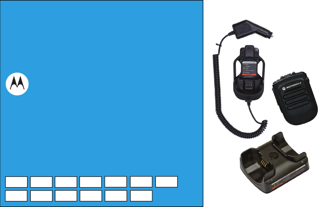
WIRELESS RSM FOR
PORTABLES SOLUTIONS
USER GUIDE
ACCESSORIES
PMMN4096 WIRELESS REMOTE SPEAKER MICROPHONE
PMLN6714 DUAL-UNIT CHARGER
PMLN6716 VEHICULAR CHARGER
PMNN4461 WIRELESS REMOTE SPEAKER MICROPHONE BATTERY
en-US fr-CA es-LA pt-BR ko-KR de-DE
fr-FR it-IT nl-NL pt-PT ru-RU uk-UA
es-ES
BackCover.fm Page 1 Wednesday, November 9, 2016 11:11 AM

FOREWORD
English
i
CHAPTER 1: FOREWORD
Important Safety Information
RF Energy Exposure and Product Safety Guide
for Portable Two-Way Radios
ATTENTION!
This radio is restricted to Occupational use only.
Before using the radio, read the RF Energy Exposure and Product
Safety Guide for Portable Two-Way Radios which contains important
operating instructions for safe usage and RF energy awareness and
control for Compliance with applicable standards and Regulations.
For a list of Motorola Solutions-approved antennas, batteries, and other
accessories, visit the following website:
http://www.motorolasolutions.com/APX
Under Industry Canada regulations, this radio transmitter may only
operate using an antenna of a type and maximum (or lesser) gain
approved for the transmitter by Industry Canada. To reduce potential
radio interference to other users, the antenna type and its gain should
be so chosen that the equivalent isotropically radiated power (e.i.r.p.) is
not more than that necessary for successful communication.
Notice to Users (FCC and Industry Canada)
This device complies with Part 15 of the FCC rules and Industry
Canada's license-exempt RSS's per the following conditions:
•This device may not cause harmful interference.
•This device must accept any interference received, including
interference that may cause undesired operation.
•Changes or modifications made to this device, not expressly
approved by Motorola, could void the authority of the user to operate
this equipment.

FOREWORD
English
ii
Consignes de sécurité importantes
Radios bidirectionnelles portatives : exposition
aux radiofréquences et sécurité du produit
ATTENTION!
Cette radio ne doit être utilisée qu'à des fins professionnelles. Avant
d'utiliser la radio, lisez le guide Radios bidirectionnelles portatives :
exposition aux radiofréquences et sécurité du produit, qui contient
d'importantes instructions de fonctionnement pour une utilisation
sécuritaire et des informations sur l'exposition aux fréquences
radioélectriques, dans le but d’assurer votre conformité aux normes et
règlements en vigueur.
Visitez le site Web suivant pour obtenir la liste des antennes, des
batteries et des autres accessoires approuvés par Motorola :
http://www.motorolasolutions.com/APX
Selon la réglementation d'Industrie Canada, cet émetteur radio ne peut
être utilisé qu'avec une antenne dont le type et le gain maximal (ou
minimal) sont approuvés par Industrie Canada pour cet émetteur. Afin
de limiter les interférences radio pour les autres utilisateurs, le type et le
gain de l'antenne doivent être choisis de façon à ce que la puissance
isotrope rayonnée équivalente (P.I.R.E.) ne soit pas plus forte qu'il ne le
faut pour établir la communication.
Avis aux utilisateurs (FCC et Industrie Canada)
Cet appareil est conforme à la partie 15 des règles de la FCC et
d'Industrie Canada permis exemptés RSS de par la conditions
suivantes:
•Ce dispositif ne doit pas causer d'interférences nuisibles.
•Cet appareil doit accepter toute interférence reçue, y compris les
interférences qui peuvent perturber le fonctionnement.
•Les changements ou les modifications apportées à ce dispositif, non
expressément approuvées par Motorola, peuvent annuler le droit de
l'utilisateur à utiliser cet équipement.

FOREWORD
English
iii
Battery Information:
Battery is shipped with a nominal charge between 30% and 50%.
Battery should be stored between -10 °C (14 °F) and 30 °C (86 °F) to
minimize permanent capacity loss.
CAUTION: Storing your fully charged accessory in high-temperature
conditions may permanently reduce the life of the internal
battery.
Important Information:
•Hold the microphone in a vertical position with the microphone at
least one inch (2.5 centimeters) away from the nose or lips.
•Body Worn Operation. When microphone is worn on the body, always
use Motorola-approved clip for this product. Using approved body-
worn accessories is important because the use of non-Motorola-
approved accessories may result in exposure levels, which exceed
the FCC occupational/controlled environment RF exposure limits.
•Use only Motorola-approved supplied or replacement batteries. Use
of non-Motorola-approved batteries may exceed the applicable RF
exposure guidelines (iEEE, ICNIRP or FCC).
•DO NOT charge your accessory in temperatures below 0 °C (32 °F)
or above 45 °C (113 °F). DO NOT store your accessory in direct
sunlight or where expected temperatures can exceed this range such
as inside a parked car.
•Storing your fully charged accessory in high-temperature conditions
may permanently reduce the life of the internal battery.
•Battery life may temporarily shorten in low-temperature conditions.
Acoustic Safety
Exposure to loud noises from any source for extended periods of time
may temporarily or permanently affect your hearing. The louder the
radio's volume, the less time is required before your hearing could be
affected. Hearing damage from loud noise is sometimes undetectable at
first and can have a cumulative effect.
To protect your hearing:
•Use the lowest volume necessary to do your job.
•Turn up the volume only if you are in noisy surroundings.
•Turn down the volume before adding headset or earpiece.
•Limit the amount of time you use headsets or earpieces at high
volume.
•When using the radio without a headset or earpiece, do not place the
radio's speaker directly against your ear.
CHARGERS SAFETY INFORMATION
Important Safety Information
This document contains important safety and operating
instructions. Please read these instructions carefully and save
them for future reference.
Before using the battery charger, read all the instructions and cautionary
markings on (1) the Dual-Unit Charger / Vehicular Charger, (2) the
battery, and (3) on the Wireless Remote Speaker Microphone (WRSM).

FOREWORD
English
iv
WARNINGS
NOTE: The Dual-Unit Charger is not designed to accommodate the
alkaline battery tray.
OPERATIONAL SAFETY GUIDELINES
Dual-Unit Charger PMLN6714_
•This equipment is not suitable for outdoor use. Use only in dry
locations/conditions.
•Ensure the WRSM with attached battery or battery alone is dry before
inserting into the Dual-Unit Charger.
•Connect equipment only to an appropriately wired power supply of
the correct voltage (as specified on the product). Disconnect from line
voltage by removing main plug.
•The socket outlet to which this equipment is connected should be
close by and easily accessible.
•Maximum ambient temperature around the Dual-Unit Charger
equipment must not exceed 50 °C (122 °F).
•Output voltage from the power supply unit must not exceed the
ratings stated on the product label located on the power supply.
•Make sure the cord is located where it will not be stepped on, tripped
over, or subjected to water, damage, or stress.
!
W A R N I N G
!
2. Use of accessories not recommended by Motorola may result in
risk of fire, electric shock, or injury.
3. To reduce risk of damage to the electric plug and cord of the
DUC, pull by the plug rather than the cord when disconnecting
the charger.
4. To reduce risk of damage to the CLA and cord of the Vehicular
Charger, pull by the CLA rather than the cord when disconnecting
the charger.
5. An extension cord should not be used unless absolutely
necessary. Use of an improper extension cord could result in risk
of fire and electric shock. If an extension cord must be used,
make sure that the cord size is 18 AWG for lengths of up to
100 feet (30.48 m), and 16 AWG for lengths up to 150 feet
(45.72 m).
6. To reduce risk of fire, electric shock, or injury, DO NOT operate
the charger if it has been broken or damaged in any way. Take it
to a qualified Motorola service representative.
7. DO NOT disassemble the charger – it is not repairable and
replacement parts are not available. Disassembly of the charger
may result in risk of electric shock or fire.
8. To reduce risk of electric shock of the DUC, unplug the charger
from the AC outlet before attempting any maintenance or
cleaning.
9. To reduce risk of electric shock of the Vehicular Charger, unplug
the Vehicular Charger from the CLA power source before
attempting any maintenance or cleaning.
10. This is a class A product. In a domestic environment this product
may cause radio interference in which case the user may be
required to take adequate measures.
1. To reduce risk of injury, charge only the rechargeable
Motorola authorized batteries listed in Table 1.1. Other
batteries may explode, causing personal injury and
damage.
Table 1.1: Motorola Authorized Battery
Kit (Part) Number Platform/Description
PMNN4461_ Battery Standard Li-Ion 1750M1880T

FOREWORD
English
v
Vehicular Charger PMLN6716_
•Equipment shall be used in vehicle and in dry condition. Keep in mind
that rain or snow can reach the equipment i.e. through an open
vehicle window.
•Ensure the WRSM with attached battery or battery alone is dry before
inserting into the Vehicular Charger.
•Connect equipment only to an appropriately vehicle’s cigar lighter
socket of the correct voltage (as specified on the product).
Disconnect from line voltage by removing the CLA.
•Maximum ambient temperature around the Vehicular Charger
equipment must not exceed 60 °C (140 °F).
•Output voltage from the vehicle’s cigar lighter socket unit must not
exceed the ratings stated on the product label located at the back of
the charger.
•Make sure the cord is located where it will not be stepped on, tripped
over, or subjected to water, damage, or stress.
RADIO COMPATIBILITY
The Wireless Remote Speaker Microphone (WRSM) is compatible with
the radios listed below:
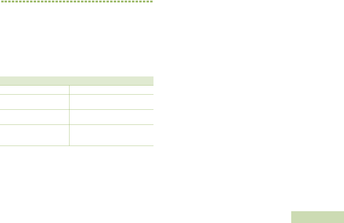
Table 1.2: Radios Compatibility
Kit (Part) Number Platform/Description
North America
XPR7550, XPR7580, XPR7350,
XPR7380, XPR7550e, XPR7580e,
XPR7350e, and XPR7380e
Latin America DGP8550e, DGP5550e, DGP8050e,
DGP5050e, and DGP8050e
European
DP4801e, DP4601e, DP4401e, DP4801,
DP4601, DP4401, DP3441e, and
DP3661e
Asia Pacific and Middle
East
DP4801e, DP4601e, DP4401e, DP4801,
DP4601, DP4401, DP3441e, and
DP3661e

FOREWORD
English
vi
WAVE 5000 MOBILE CLIENT AND RADIO
CONFIGURATION
By default, the WRSM is compatible with the radio ONLY. To work with
WAVE 5000 Mobile Client, choose WAVE 5000 on Operation Mode at
Accessory Programming Software (APS).
WAVE5000 Mobile Client Android Application Package (APK) version
TBD and above must be used for compatibility with the WRSM. This can
be configured using the APS tool.
The APS tool allows you to select two modes of operation:
•Radio mode – configuring the WRSM to be used with your radio.
Refer to Table 1.2 for radios compatible to the WRSM.
•Wave5k mode – configuring the WRSM to be used with the Wave
5000 Mobile Client on a smartphone.
WIRELESS RSM PMMN4096_
English
1
CHAPTER 2: WIRELESS RSM
PMMN4096_
PREPARING YOUR WRSM FOR USE
Assemble your WRSM by following these steps:
Assembling the Swivel Clip . . . . . . . . . . . . . . . . . . . . . . . . . . . . page 2
Attaching the Battery . . . . . . . . . . . . . . . . . . . . . . . . . . . . . . . . . page 2
Detaching the Battery. . . . . . . . . . . . . . . . . . . . . . . . . . . . . . . . . page 3
Charging the Battery . . . . . . . . . . . . . . . . . . . . . . . . . . . . . . . . . page 3
Language Selection . . . . . . . . . . . . . . . . . . . . . . . . . . . . . . . . . . page 4
Recommended Wearing Positions. . . . . . . . . . . . . . . . . . . . . . . page 5
WIRELESS RSM PMMN4096_
English
2
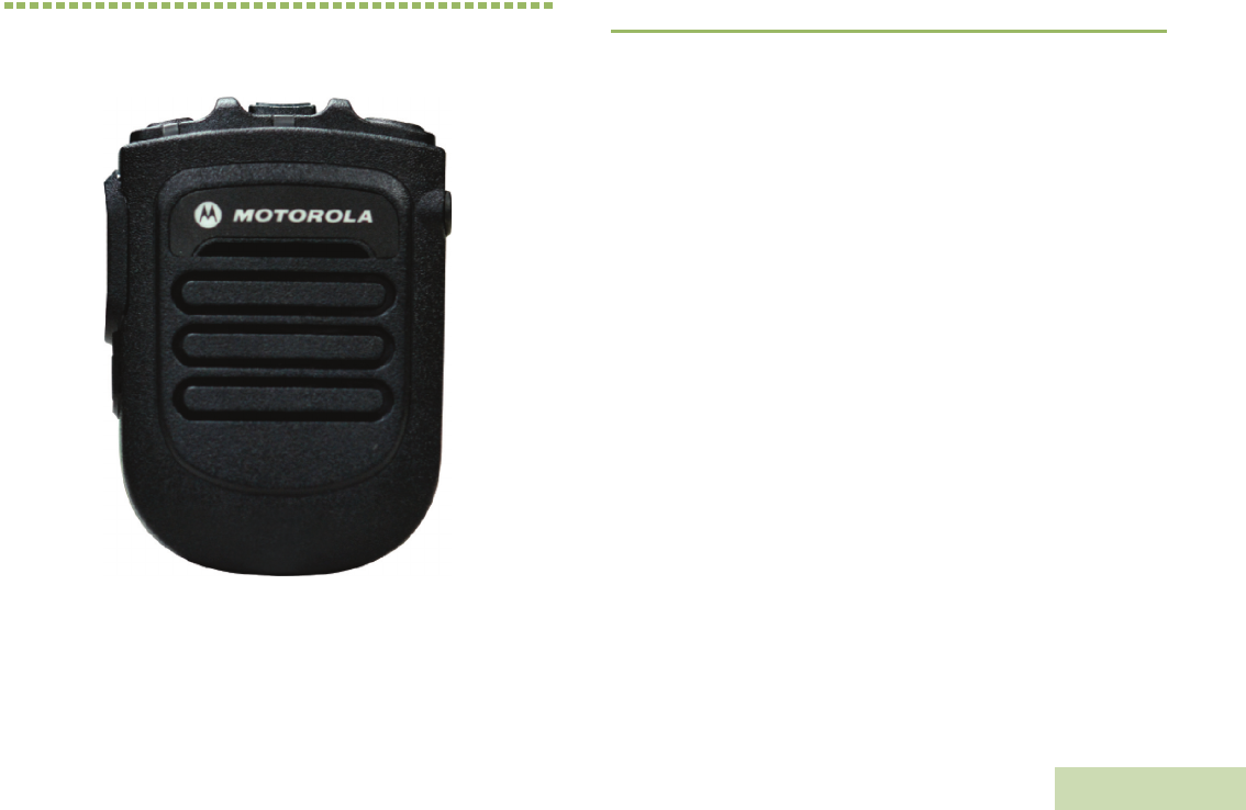
Assembling the Swivel Clip
Insert the swivel clip through the battery slot. Rotate the clip to the right
position as indicated in Figure 2.1 below.
Figure 2.1: Assembling the swivel clip
Attaching the Battery
With the WRSM turned off, align the battery to back chassis and fully
slot in until the battery latch is engaged.
Figure 2.2: Attaching the battery into the WRSM
2
1
1
2
WIRELESS RSM PMMN4096_
English
3
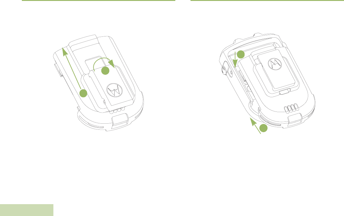
Detaching the Battery
To detach the battery, lift up the battery latch and pull the battery
backward until the battery is fully disengaged from the back chassis.
Figure 2.3: Removing the battery from the WRSM
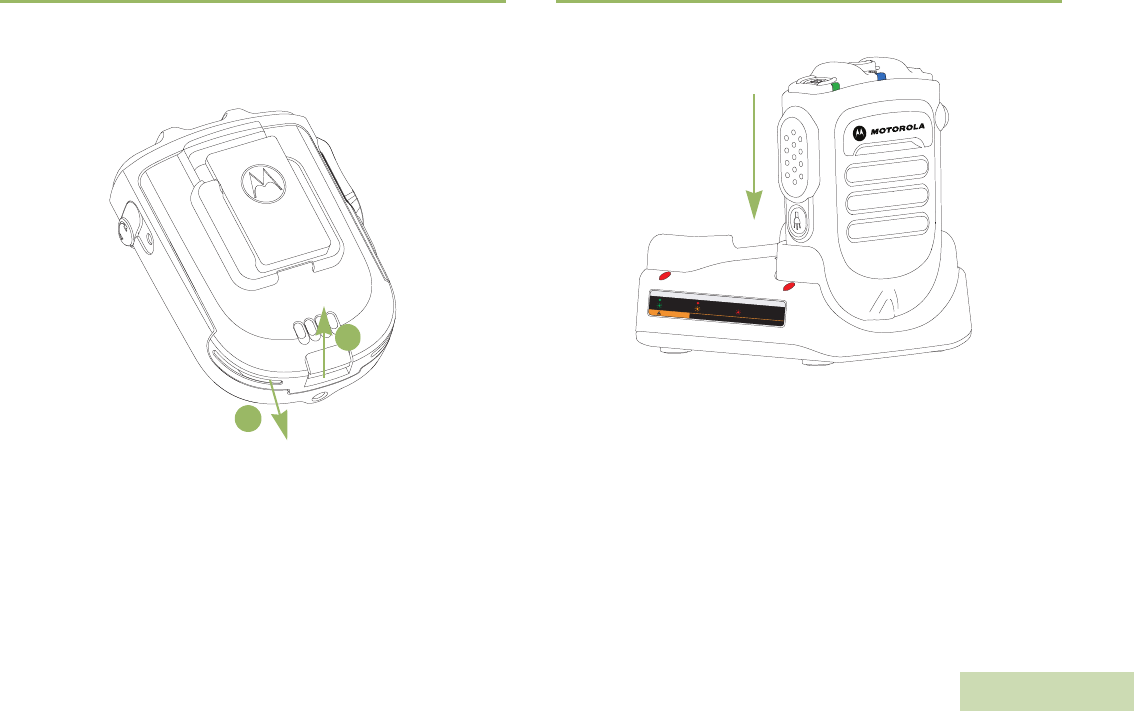
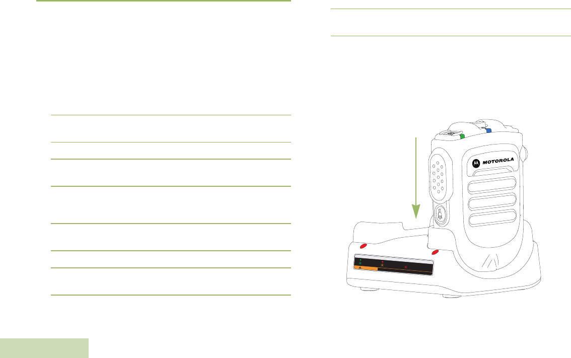
Charging the Battery
Figure 2.4: Charging position of the WRSM with battery attached
1
2
LED STATUS INDICATORS
Ready
>90%
CAUTION
Charging
Standby
RISK OF FIRE. REFER TO MANUAL FOR BATTERY TYPE
Unable to Charge

WIRELESS RSM PMMN4096_
English
4
The Motorola-approved battery shipped with your WRSM is uncharged.
Prior to using a new battery, fully charge the new battery to ensure
optimum capacity and performance.
NOTE: When charging a battery attached to a WRSM, turn the
WRSM OFF to ensure a full charge.
Battery Charger
To charge the battery, place the battery, with or without the WRSM, in a
Motorola-approved charger. When initially inserting the battery into the
charger, the charger’s LED will turn red. DO NOT use WRSM until the
charger’s LED turn Green,
The charger’s LED indicates the charging progress; see Chapter 3 and
Chapter 4 or the label printed on the charger.
Align the slot of the battery with the charger’s rail and slot in. Refer to
Figure 2.4.
Language Selection
Follow the procedure below if you want to reset to your desired
language. Ensure that the WRSM is powered OFF before starting this
procedure.
Procedure:
1Press and hold the PTT button before powering ON the WRSM.
DO NOT release the PTT button.
2Continue holding the PTT Button after clearing the Bluetooth
Information (refer to Pairing Your WRSM) until you hear the
language selection prompts to enter the language selection feature.
3Select your desired language by pressing the PTT button. Refer to
Table 2.1 below for the Language Selection Indicators.
To avoid a possible explosion:
•DO NOT replace the battery in any area labeled
“hazardous atmosphere”.
•DO NOT discard batteries in a fire.
!
W A R N I N G
!
Table 2.1: Language Selection Indicators
State Power Indication LED Voice Prompt
Language Selection LED illuminated
“For English press PTT
now” (Menu selection
prompts)
WIRELESS RSM PMMN4096_
English
5
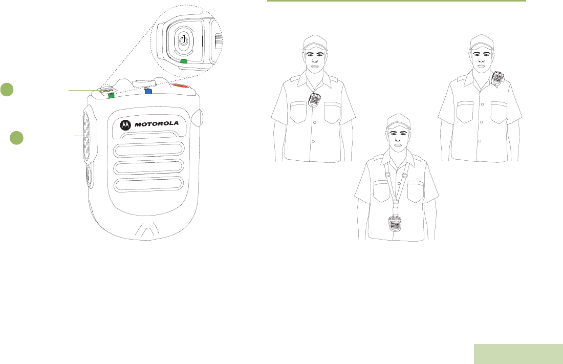
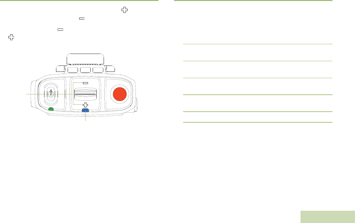
Figure 2.5: Language Selection
Recommended Wearing Positions
For optimum performance, wear the WRSM as highlighted in Figure 2.6
below.
Figure 2.6: Recommended wearing positions
NOTE: When the WRSM is worn on the body, always use Motorola-
approved clip. Using approved body-worn accessories is
important because the use of non-Motorola-approved
accessories may result in exposure levels, which exceed the
FCC occupational/controlled environment RF exposure limits.
1
2Push-to-Talk
(PTT) Button
Power Button /
Multi Function
Button (MFB)
WIRELESS RSM PMMN4096_
English
6
IDENTIFYING WRSM INDICATORS AND
CONTROLS
Take a moment to review the following:
Overview of the WRSM . . . . . . . . . . . . . . . . . . . . . . . . . . . . . . . page 6
Power Indicators and Battery Alerts . . . . . . . . . . . . . . . . . . . . . page 7
Audio Indicators. . . . . . . . . . . . . . . . . . . . . . . . . . . . . . . . . . . . . page 7
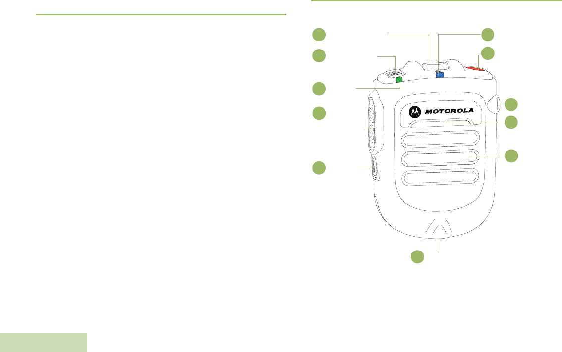
Overview of the WRSM
Figure 2.7: Wireless Remote Speaker Microphone Overview
Audio Indicator
1
2Programmable
Button
(Orange Button)
Audio Jack
3
Microphone
4
Speaker
5
Tasklight
6
Tasklight
Button
7
Push-to-Talk
(PTT) Button
8
Power
Indicator
9
10 Power Button /
MFB
11 Volume Toggle
WIRELESS RSM PMMN4096_
English
7
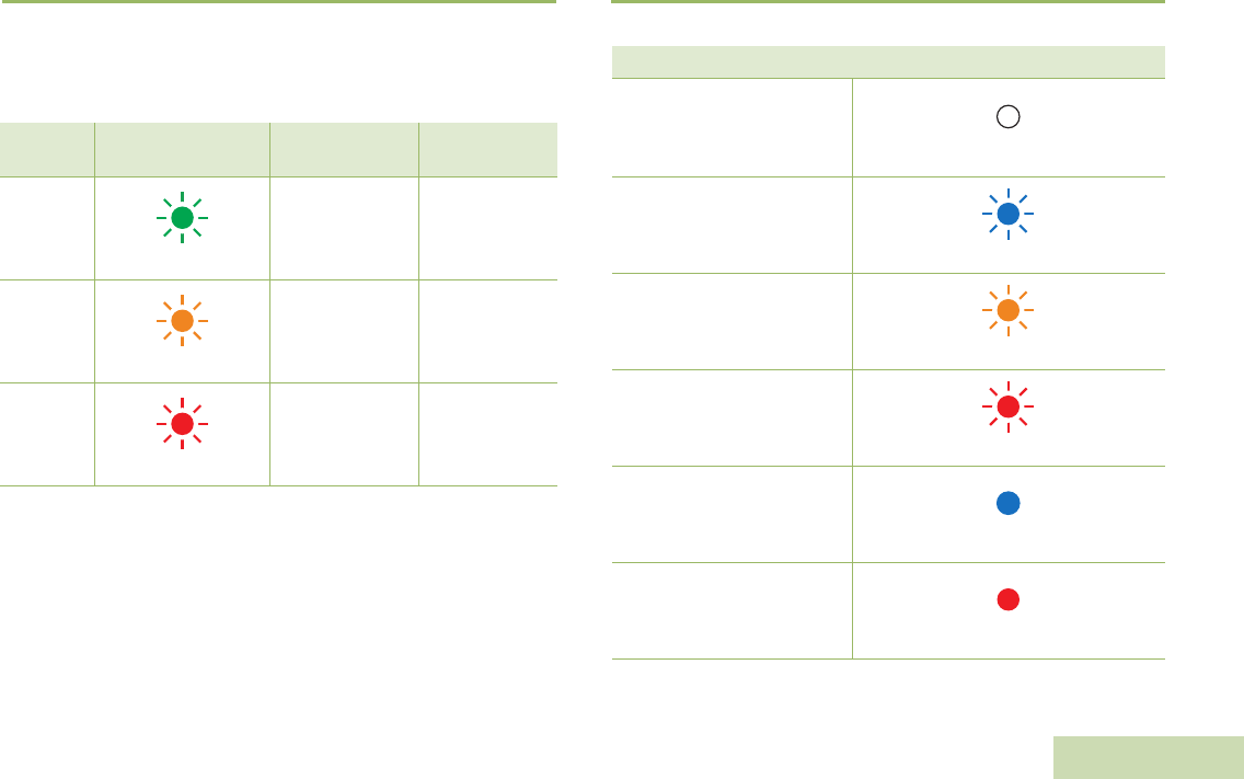
Power Indicators and Battery Alerts
The WRSM is battery powered. It is very important to pay attention to
the low battery warning described in Table 2.2 to avoid improper
functioning of the WRSM.
Audio Indicators
Table 2.2: Power Indicators and Battery Alerts
State Power Indication
LED Tone Indication Remaining
Battery Life
Normal
Battery
Green
No tone
11 hours
(full charged) –
30 minutes
Low
Battery
Amber
Low Battery tone
every 2 minutes
Less than
30 minutes
Critical
Battery
Red
Low Battery tone
every 30 seconds
Less than
10 minutes
Table 2.3: Audio Indicators
State Audio Indication LED
Audio Not Available,
Device Not Paired
OFF
Audio Available,
Good Signal
Blue Blink
Audio Available,
Poor Signal / Edge of Range
Amber Blink
Audio Available,
Muted
Red Blink
Audio Not Available,
Disconnected / Reconnecting
Blue Solid
Audio Not Available,
Disconnected / Reconnecting
and Muted Red Solid
WIRELESS RSM PMMN4096_
English
8
GENERAL WRSM OPERATION
Once you understand how your WRSM is configured, you are ready to
use your WRSM. Use this navigation guide to familiarize yourself with
the basic features:
Powering ON/OFF the WRSM . . . . . . . . . . . . . . . . . . . . . . . . . page 8
Volume Control . . . . . . . . . . . . . . . . . . . . . . . . . . . . . . . . . . . . . page 9
Pairing Your WRSM. . . . . . . . . . . . . . . . . . . . . . . . . . . . . . . . . . page 9
Subsequent Connection . . . . . . . . . . . . . . . . . . . . . . . . . . . . . page 10
Poor Signal / Out Of Range Warning Indication . . . . . . . . . . . page 10
Programmable Button (Orange Button). . . . . . . . . . . . . . . . . . page 11
Tasklight Button. . . . . . . . . . . . . . . . . . . . . . . . . . . . . . . . . . . . page 11
Dark Mode. . . . . . . . . . . . . . . . . . . . . . . . . . . . . . . . . . . . . . . . page 11
Secondary Receiver Audio Accessory. . . . . . . . . . . . . . . . . . . page 12
Failure Detected Indication and Handling . . . . . . . . . . . . . . . . page 13
Troubleshooting. . . . . . . . . . . . . . . . . . . . . . . . . . . . . . . . . . . . page 13
Firmware Upgrade. . . . . . . . . . . . . . . . . . . . . . . . . . . . . . . . . . page 13
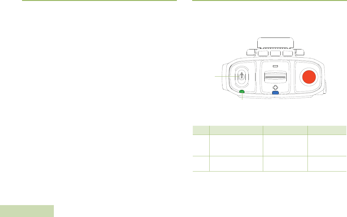
Powering ON/OFF the WRSM
To power ON the WRSM, press and hold the Power Button until you
hear “Motorola Solutions” prompt. To power OFF, press the Power
Button until the WRSM turns off.
Figure 2.8: Powering on your WRSM
Table 2.4: Power ON/OFF LED and Tone Indicators
Power Power Indication LED Tone Indication Voice Prompt
ON LED blinks 3 times “Motorola
Solutions”
“Motorola
Solutions,
Power On”
OFF LED blinks 3 times then
OFF Power Off tone “Power Off”
Power
Button
Power Indicator
WIRELESS RSM PMMN4096_
English
9
Volume Control
To increase the volume, push volume lever towards the . To decrease
the volume, push lever towards the .
To mute, hold lever to the for 2 seconds. To unmute, push lever to
the or press the PTT button. Volume returns to the previous level.
Figure 2.9: Volume Control
The color of the Audio Indicator LED changes according to Table 2.3 on
page 7.
Pairing Your WRSM
Procedure:
1Verify that both the host and the WRSM are powered ON (First time
only: Once the WRSM is powered ON, if not previously selected,
the WRSM will instruct the user to select language or tone, and then
it goes into Pairing Mode automatically.).
2Both the WRSM and wireless host must be within pairing range
(recommended pairing range is within 1 meter).
3Once the devices are paired successfully, a “Pairing Successful”
tone or “Connecting” voice prompt is played on the WRSM.
4Press the MFB button to start the connection process when you
hear the “Ring” tone indicating Host is requesting for connection.
5Wireless Link Connected with Host indication is provided upon
successful link establishment (refer to Table 2.5 on page 10).
6Your WRSM is now ready to be used.
Volume
Toggle
Audio Indicator

WIRELESS RSM PMMN4096_
English
10
Subsequent Connection
Same Host:
If the Bluetooth link is lost, connection will be automatically
reestablished when the host and device come within 10 meter range
(line-of-sight).
New Host:
1Put the wireless device in Pairing Mode by powering ON while
pressing the PTT button simultaneously.
2Follow steps from Pairing Your WRSM.
Poor Signal / Out Of Range Warning
Indication
You will be prompted with the Poor Signal / Ouf Of Range Warning
Indication if the WRSM is about to lose the wireless link at Bluetooth
fringe area.
This warning indication will turn off if the user moves closer or if the
signal quality improves.
Refer to Table 2.6below for the Poor Signal / Out Of Range Indication:
Table 2.5: Wireless Link and Pairing Indicators
State Indication LED Tone
Indication Voice Prompt
Not Paired Blue LED blinking Pairing Ready
tone
“Searching for
Host”
Paired
Successfully
Blue LED Solid
for 2 seconds
Pairing
Successful tone “Connecting”
Wireless Link
Connected with
Host
Blue LED
Heartbeat:
Long OFF and
Short ON
Connected tone “Headset
Connected”
Wireless Link
Disconnected
from Host
Blue LED Solid
ON
Disconnected
tone every
2 minutes
for 10 minutes
“Headset
Disconnected”
Table 2.6: Poor Signal / Out Of Range Warning Indicator
State Audio Indication LED Tone Indication
Poor Signal /
Ouf Of Range
Amber LED illuminated for
2 seconds “Bad Bonk” Tone

WIRELESS RSM PMMN4096_
English
11
Push-to-Talk (PTT) Button
Press and hold down the PTT button to talk. Release the PTT button to
listen. The microphone is activated when the PTT button is pressed.
Figure 2.10: Pressing Push-to-Talk Button
Programmable Button (Orange Button)
This Programmable Button is mapped to the Accessory Orange Button
for Portable Radios. Pressing the Programmable Button on the WRSM
will trigger the event set in Accessory Orange Button. The Accessory
Orange Button is programmable through radio’s Customer
Programming Software (CPS). Your radio’s User Guide contains a full
description of the programmable functions that are available through
this button.
Tasklight Button
Press the Tasklight Button for 1 second to switch ON/OFF the tasklight.
During low/critical battery, the Tasklight blinks for 30 seconds and will be
auto switched OFF.
NOTE: The Tasklight is disabled when WRSM is in Dark Mode.
Dark Mode
Dark Mode allows you to turn OFF the LEDs on the WRSM.
IMPORTANT: When the WRSM is in Dark Mode and muted state, all
indications will be turned OFF.
To activate the Dark Mode feature, follow the steps below:
Procedure:
1Press and hold the Tasklight Button until Dark Mode is ON. The
Tasklight will blink for 1 second upon entering/exiting Dark Mode.
2Refer to Table 2.7 below for the Dark Mode Indicators.
NOTE: To disable the Dark Mode feature, press the Tasklight Button
for 3 seconds.
WIRELESS RSM PMMN4096_
English
12
NOTE: All three LEDs (Power Indicator, Audio Indicator & Tasklight)
blink for 1 second and off at the same time when turning ON/
OFF the Dark Mode.
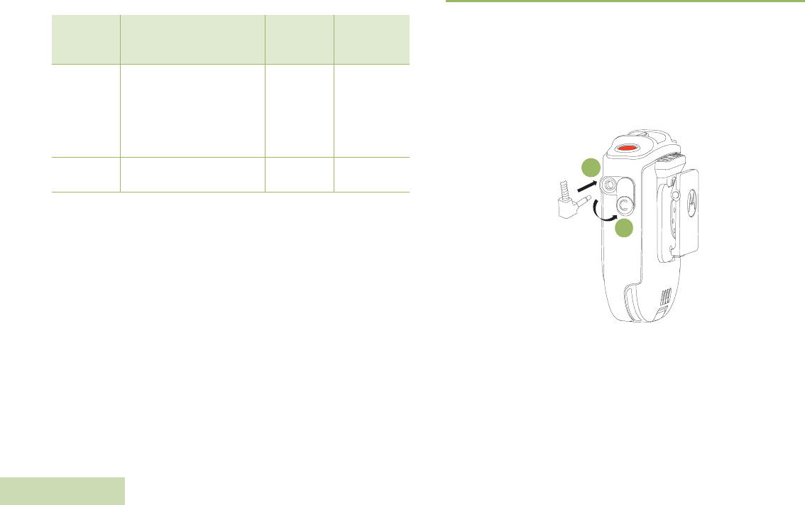
Secondary Receiver Audio Accessory
When a secondary accessory is plugged into the audio jack, audio will
be routed through secondary accessory
Attaching Secondary Receiver Audio Accessory
Lift up the dust cover and rotate 90 o. Plug the dust cover to the housing
slot. Insert the secondary receiver audio accessory to 3.5 mm audio
jack.
Figure 2.11: Attaching secondary receiver audio accessory
Table 2.7: Dark Mode Indicators
Indication
Power Indication, Audio
Indication and Tasklight
LED
Tone
Indication Voice Prompt
Dark Mode
ON
LED illuminated for 1
second then OFF
“Dark Mode”
tone
“Lights OFF,
Press and
hold Tasklight
Button to
switch lights
ON”
Dark Mode
OFF
LED illuminated for 1
second
“Dark Mode ”
tone “Lights ON”
1
2
WIRELESS RSM PMMN4096_
English
13
Optional Accessories
NOTE: Some part numbers may have regional prefix such as AA,
MD or AZ.
Failure Detected Indication and Handling
Any product error is indicated by alternating Red and Green blinks and
a failure detected indication (tone / voice prompt) will be heard. A few
seconds later the WRSM will recover.
Troubleshooting
If at any time the wireless connection cannot be re-established, or the
WRSM is operating incorrectly:
Procedure:
1Power cycle the WRSM and the two-way radio.
2Refer to “Pairing Your WRSM" on page 9” to repeat the connection
process.
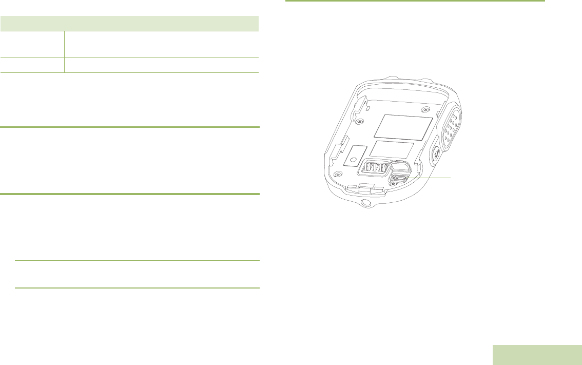
Firmware Upgrade
Firmware upgrade is available for this WRSM and it is only upgradeable
by your dealer. Check with your dealer for more information on the latest
firmware upgrades.
NOTE: DO NOT charge the WRSM with this micro USB port, it is
strictly for firmware upgrade only.
Figure 2.12: Location of the micro USB port
Table 2.8: Optional Accessories
Part Number Description
RLN4941_ Earpiece with Coiled Cord and 3.5 mm RT Angle
Plug
RLN4885_ Receiver Earbud for Remote Speaker Microphone
Micro USB port

WIRELESS RSM PMMN4096_
English
14
NOTES
DUAL-UNIT CHARGER PMLN6714_
English
15
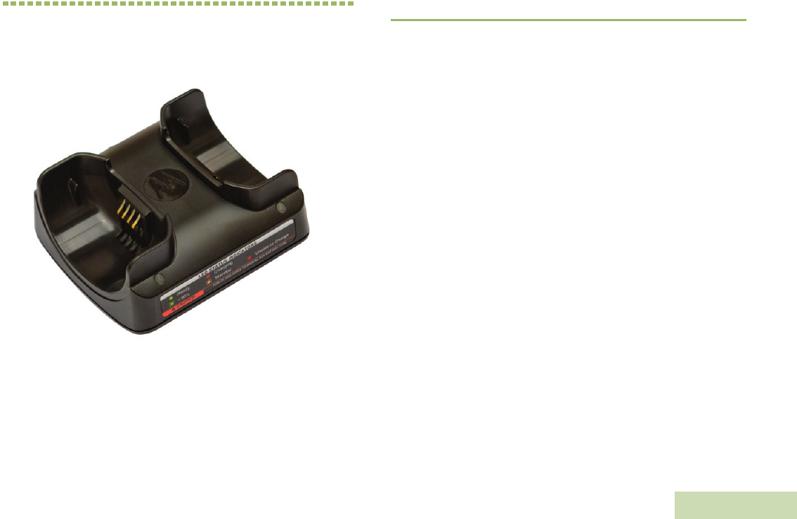
CHAPTER 3: DUAL-UNIT CHARGER
PMLN6714_
The Dual-Unit Charger is intended for use with the Motorola-approved
Lithium-ion rechargeable batteries (listed in Table 3.1). Both pockets are
capable in charging Wireless Remote Speaker Microphone (WRSM)
with battery or battery alone.
An illuminated LED indicates the state of charge for the first and second
pocket.
PREPARING YOUR DUC FOR USE
Take a moment to review the following:
Operational Guidelines. . . . . . . . . . . . . . . . . . . . . . . . . . . . . . . page 24
Motorola Authorized Battery. . . . . . . . . . . . . . . . . . . . . . . . . . . page 24
Motorola Authorized Power Sources/Power Supplies . . . . . . . page 24
Overview of the DUC . . . . . . . . . . . . . . . . . . . . . . . . . . . . . . . . page 25
Operating Instructions . . . . . . . . . . . . . . . . . . . . . . . . . . . . . . . page 26
LED Light Indication . . . . . . . . . . . . . . . . . . . . . . . . . . . . . . . . . page 27
Troubleshooting . . . . . . . . . . . . . . . . . . . . . . . . . . . . . . . . . . . . page 28

DUAL-UNIT CHARGER PMLN6714_
English
16
Operational Guidelines
•Always remember to power ON the Dual-Unit Charger first before
inserting the WRSM with the attached battery or battery alone into
the pocket.
•The Dual-Unit Charger is designed to provide simultaneous charging
for both pockets.
Motorola Authorized Battery
The battery listed in Table 3.1 is approved for use with the Dual-Unit
Charger.
NOTE: The Dual-Unit Charger is not designed to accommodate the
alkaline battery tray.
Motorola Authorized Power Sources/Power
Supplies
The Power Sources/Power Supplies listed in Table 3.2 are approved for
use with the Dual-Unit Charger:
* Charger only UL approved when shipped with this power supply.
(Applicable for North America region only)
Table 3.1: Motorola Authorized Battery
Kit (Part) Number Platform/Description
PMNN4461_ Battery Standard Li-Ion 1750M1880T
Table 3.2: Motorola Authorized Power Supply
Power Supply Kit
Number Description
25012022001* Power Supply, Charger Switch Mode, 110 – 240 V
US/NA/JPN/TAIWAN
25012022002 Power Supply, Charger Switch Mode, 110 – 240 V
EURO
25012022003 Power Supply, Charger Switch Mode, 110 – 240 V
UK
25012022004 Power Supply, Charger Switch Mode, 110 – 240 V
CHINA
25012022006 Power Supply, Charger Switch Mode, 110 – 240 V
AUS/NZ
25012022007 Power Supply, Charger Switch Mode, 110 – 240 V
BRZ
25012022008 Power Supply, Charger Switch Mode, 110 – 240 V
ARG
25012022009 Power Supply, Charger Switch Mode, 110 – 240 V
KOR
DUAL-UNIT CHARGER PMLN6714_
English
17
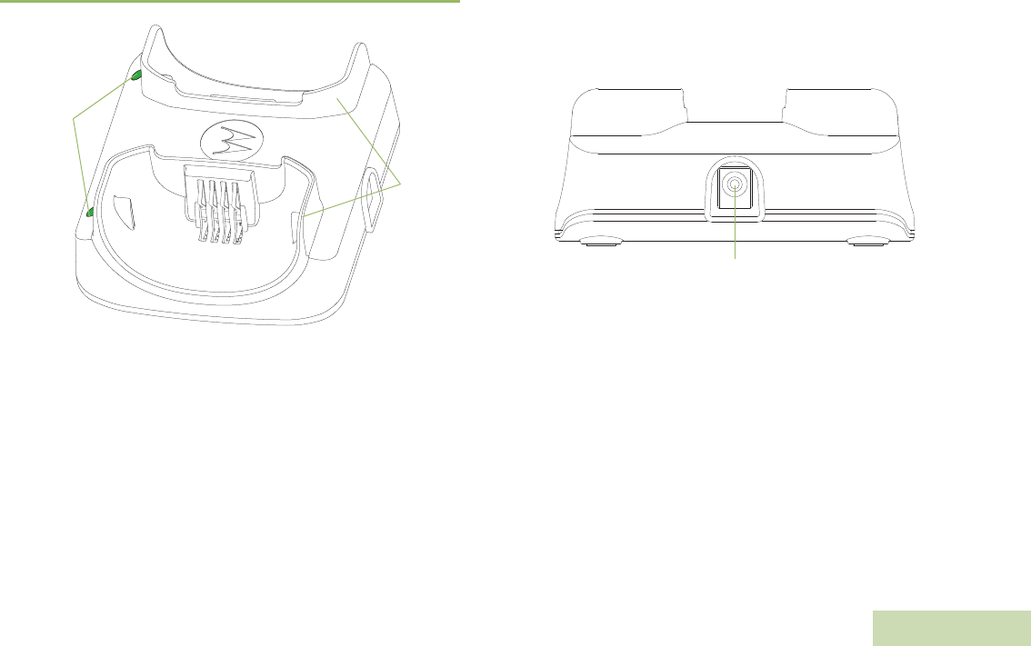
Overview of the DUC
Figure 3.1: Dual-Unit Charger (Front View) Figure 3.2: Dual-Unit Charger (Side View)
Pocket
LEDs
Barrel Connector
DUAL-UNIT CHARGER PMLN6714_
English
18
Operating Instructions
Dual-Unit Chargers are intended for use only with the authorized
Motorola battery and power supplies listed in Table 3.1 and Table
3.2; usage with unauthorized products may prevent proper
operation and may damage the device.
The battery charger will accommodate a WRSM with an attached
battery or battery alone in either pocket. To charge a battery, use the
following procedure:
1Plug the power supply cord into the barrel connector on the back of
the charger.
2Plug the power supply into the appropriate AC outlet. The charger
LED will flash single green once to indicate a successful power-up.
3Insert a WRSM with battery into the charger’s pocket by:
aAligning the groove on each side of the battery with the
corresponding raised rail on each side of the charger pocket.
bSliding the WRSM with battery into the charger pocket,
ensuring complete contact between the charger and battery
contacts.
4When the WRSM with battery is properly seated in the pocket, the
charger LED will light in accordance with Table 3.3.
5Insert a battery into the charger’s pocket by:
aAligning the slot on each side of the battery with the
corresponding raised rail on each side of the charger pocket.
bSliding the battery into the charger pocket, ensuring complete
contact between the charger and battery contacts.
6When the battery is properly seated in the pocket, the charger LED
will light in accordance with Table 3.3.
NOTE: Charge new batteries overnight to ensure full charge. To
minimize charge time, it is recommended to turn the WRSM
OFF.
The Dual-Unit Charger is not designed to accommodate the
alkaline battery tray.
Figure 3.3: Charging position of the WRSM on a Dual-Unit Charger
LED STATUS INDICATORS
Ready
>90%
CAUTION
Charging
Standby
RISK OF FIRE. REFER TO MANUAL FOR BATTERY TYPE
Unable to Charge
DUAL-UNIT CHARGER PMLN6714_
English
19
LED Light Indication
When troubleshooting, always observe the color of the LED.
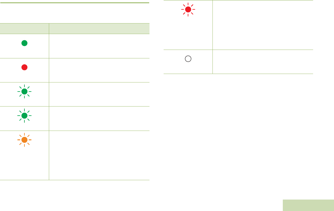
Table 3.3: Charger Status
LED Indication Charger State
Steady Green
Charged at least 95%
Steady Red
Rapid charge
Single Flash Green
Charged successfully powered up and is ready
for use
Slow Flash Green
Nearly charged at least 90%
Slow Flash Amber
Battery under voltage recovery
OR
Battery temperature is either too hot or too cold
– Wait to charge
If battery temperature is within operating
temperature, there may be a fault connection
– DO NOT charge battery
Fast Flash Red
Battery under voltage recovery time out
OR
Loss of charge current control
OR
Excessive power supply voltage
OR
Fault connection happened
– DO NOT charge battery
Off
If battery is inserted into a successfully powered
up charger, battery may have bad contact with
charger
Table 3.3: Charger Status (Continued)

DUAL-UNIT CHARGER PMLN6714_
English
20
Troubleshooting
If There is Fast Flash Red Indication:
1Confirm the battery being used with the WRSM is listed in Table 3.1
and is good in condition.
2Confirm that the power supply being used with the WRSM is listed
in Table 3.2 and is good in condition.
3Remove the battery and restart the Dual-Unit Charger.
4If the symptom persist, please send the Dual-Unit Charger to the
nearest Service Center for further verification.
If There is No LED Indication:
1Check that the WRSM with battery or the battery is inserted
correctly in the pocket.
2Make sure that the power supply is plugged into an appropriate AC
outlet and the LED on the power supply is on.
3Ensure that the power supply cable is plugged securely into the
charger socket.
4Confirm that the battery being used with the WRSM is listed in Table
3.1.
5If the symptom persist, please send the Dual-Unit Charger to the
nearest Service Center for further verification.
VEHICULAR CHARGER PMLN6716_
English
21
CHAPTER 4: VEHICULAR CHARGER
PMLN6716_
The Vehicular Charger is intended for use with the Motorola-approved
Lithium-ion rechargeable batteries (listed in Table 4.1 ). The pocket is
capable in charging Wireless Remote Speaker Microphone (WRSM)
with battery or battery alone. An illuminated LED indicates the state of
charging.
PREPARING YOUR VEHICULAR CHARGER
FOR USE
Take a moment to review the following:
Operational Guidelines. . . . . . . . . . . . . . . . . . . . . . . . . . . . . . . page 30
Operating Specifications . . . . . . . . . . . . . . . . . . . . . . . . . . . . . page 30
Motorola-Authorized Battery . . . . . . . . . . . . . . . . . . . . . . . . . . page 30
Overview of Vehicular Charger . . . . . . . . . . . . . . . . . . . . . . . . page 31
Installation . . . . . . . . . . . . . . . . . . . . . . . . . . . . . . . . . . . . . . . . page 31
Operating Instructions . . . . . . . . . . . . . . . . . . . . . . . . . . . . . . . page 32
LED Light Indication . . . . . . . . . . . . . . . . . . . . . . . . . . . . . . . . . page 37
Troubleshooting . . . . . . . . . . . . . . . . . . . . . . . . . . . . . . . . . . . . page 38

VEHICULAR CHARGER PMLN6716_
English
22
Operational Guidelines
•Always remember to plug in the CLA first before inserting the WRSM
with the attached battery or battery alone into the pocket.
•The Vehicular Charger is designed to be portable.
•The WRSM is designed to be functional even when charging takes
place.
Operating Specifications
Vehicular Charger
Input voltage range: 10.8 Vdc to 33.0 Vdc
Battery Charging Interface
Max Output voltage: 4.20 Vdc
Motorola-Authorized Battery
The battery listed in Table 4.1 is approved for use with the Vehicular
Charger.
Table 4.1: Motorola-Authorized Battery
Kit (Part) Number Platform/Description
PMNN4461_ Battery Standard Li-Ion 1750M1880T
VEHICULAR CHARGER PMLN6716_
English
23
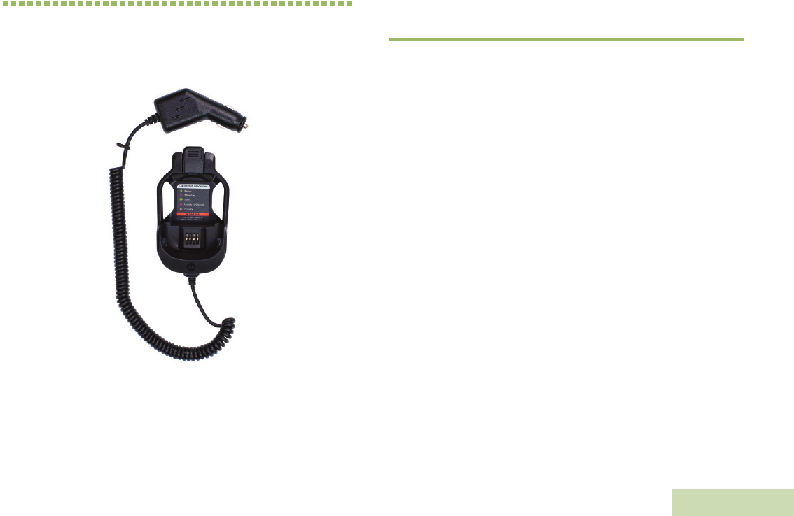
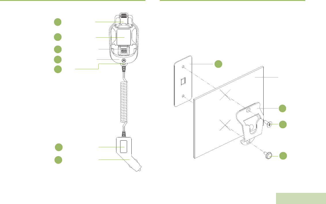
Overview of Vehicular Charger
Figure 4.1: Overview of the Vehicular Charger
Installation
Install Mounting Bracket (HLN9073_)
Refer to Figure 4.2 below and attach hang-up clip (1) to vehicle using
two sheet metal screws and back-up plate provided. Place back-up
plate (4) behind dashboard. Use flat-head screw (2) in top mounting
hole and hex-washer screw (3) in bottom mounting hole. Be certain
mounting screws fasten into holes in back-up plate.
Figure 4.2: Installing the Mounting Bracket
Release Button
1
2Warning Label /
LED Indication
Charging Contact
3
Rotating Pocket
4
LED
5
Cigarette Light
Adapter (CLA)
6
8Product Label
Vehicle
Dashboard
1
2
3
4
VEHICULAR CHARGER PMLN6716_
English
24
Operating Instructions
Vehicular Chargers are intended for use only with the authorized
Motorola battery listed in Table 4.1 ; usage with unauthorized products
may prevent proper operation and may damage the device.
Placing and Removing the Vehicular Charger from
Mounting Bracket
Figure 4.3: Removing Vehicular Charger from Mounting Bracket
Table 4.2: Mounting Brackets Description
Item Motorola Part Number Description
1 0180757T98 Hang-up Clip
2 0312002C01 Flat-Head Screw
3 0312002A01 Hex-Washer Head Screw
4 0780257N01 Back-up Plate
Mounting Bracket
Metal Stud
VEHICULAR CHARGER PMLN6716_
English
25
Figure 4.4: Placing and Removing the Vehicular Charger from the Mounting
Bracket
Mount the Charger
1Slide in the stud onto the bracket as per step (1).
Remove the Charger
1Rotate the cradle horizontally (90 °) as per step (2) & (3).
2Slide out the cradle as per step (4).
Insertion
Removal
Slide out
Slide
in
Rotate 90°
1
234

VEHICULAR CHARGER PMLN6716_
English
26
Placing and Removing the WRSM or Battery to
and from the Vehicular Charger
Placing the WRSM or Battery to the Vehicular Charger
The Vehicular Charger will accommodate a WRSM with an attached
battery or battery alone in pocket. To charge a battery, use the following
procedure:
1Plug in the CLA adaptor to CLA power supply. The charger LED will
flash single green once to indicate a successful power-up.
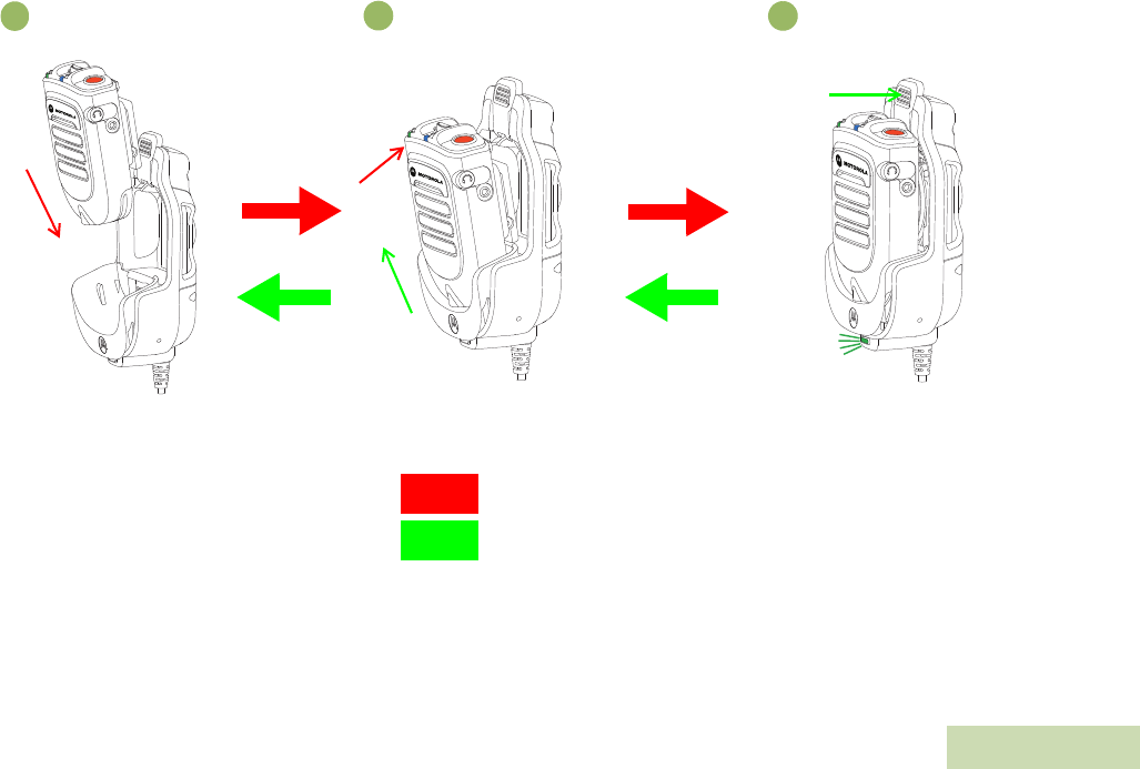
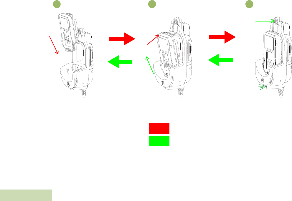
2Insert a WRSM with battery into the charger’s pocket by:
aAligning the groove on each side of the battery with the
corresponding raised rail on each side of the charger pocket per
Figure (R1).
bPressing on the front – top surface of the WRSM according to
the direction indicated in Figure (R2) to lock the WRSM into
Vehicular Charger.
3When the WRSM with battery is properly seated in the pocket, the
charger LED will light in accordance with Table 4.3 per Figure (R3).
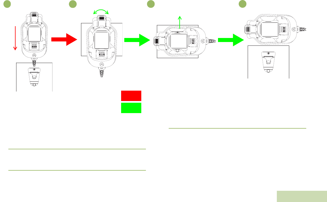
4Insert a battery into the charger’s pocket by:
aAligning the groove on each side of the battery with the
corresponding raised rail on each side of the charger pocket per
Figure (B1).
bPressing on the front – top surface of the battery according to
the direction indicated in Figure (B2) to lock the battery into
Vehicular Charger.
3When the battery is properly seated in the pocket, the charger’s
LED will light in accordance with Table 4.3 per Figure (B3).
Removing the WRSM or Battery from the Vehicular Charger
The Vehicular Charger will accommodate a WRSM with an attached
battery or battery alone in pocket. To stop charging a battery, use the
following procedure:
1Unplug the CLA from the vehicle’s cigar lighter socket.
2Remove a WRSM with battery from the charger’s pocket by:
aPressing on the Vehicular Charge’s release button to unlatch
the battery per Figure (R3).
bRemove the WRSM from the pocket by sliding the WRSM
upward per Figure (R2).
3Remove a battery from the charger’s pocket by:
aPressing on the Vehicular Charge’s release button to unlatch
the battery per Figure (B3).
bRemove the battery from the pocket by sliding the battery
upward per Figure (B2).
VEHICULAR CHARGER PMLN6716_
English
27
Attach and Remove WRSM
Figure 4.5: Attaching and Removing the WRSM from the Vehicular Charger
Insertion
Removal
Slide
in
Press
Press
Figure (R1) Figure (R2) Figure (R3)
Slide
out LED ON
1
23
VEHICULAR CHARGER PMLN6716_
English
28
Attach and Remove Battery
Figure 4.6: Attaching and Removing the Battery from the Vehicular Charger
Insertion
Removal
Figure (B1) Figure (B2) Figure (B3)
Slide
in
Press
Press
Slide
out
LED ON
1
23
VEHICULAR CHARGER PMLN6716_
English
29
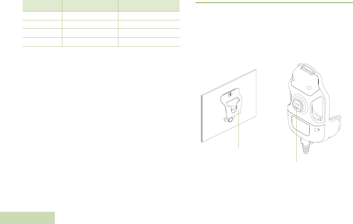
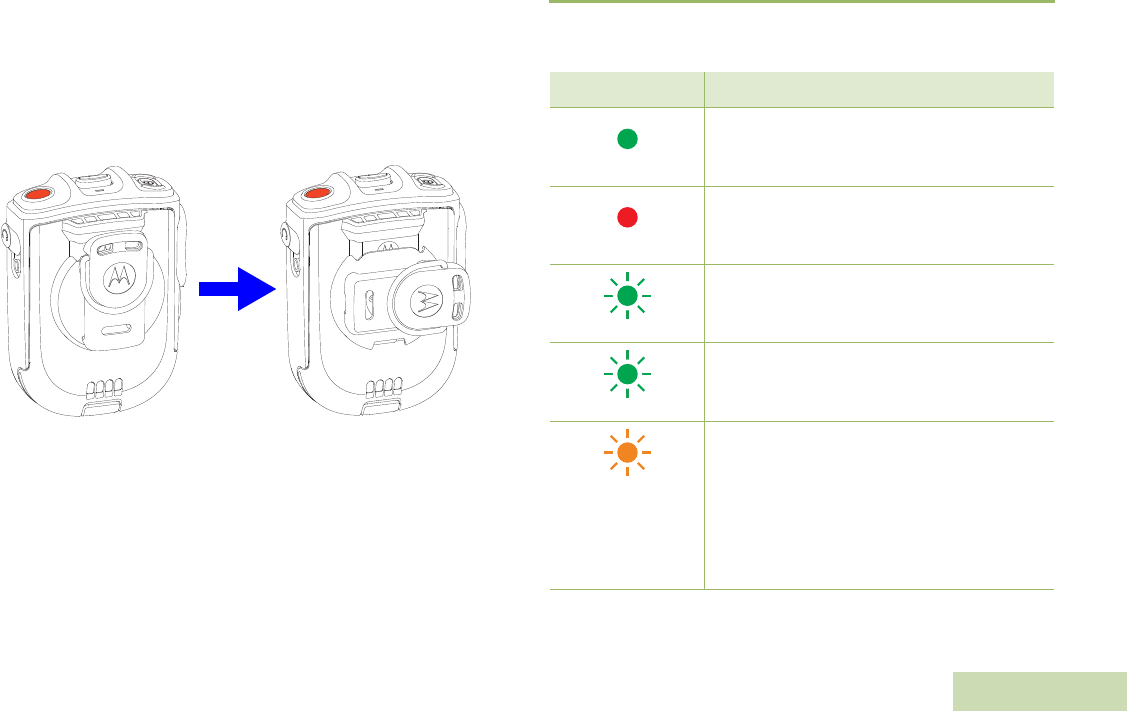
Swivel Clip Position When Placing Onto Vehicular Charger
The Vehicular Charger will accommodate for both swivel clips:
•Standard swivel clip (PMLN6743_) – Any rotational position
•D-ring swivel clip (42009312001) – Horizontal position
Rotate D-ring swivel clip to horizontal position before inserting the
WRSM or battery into the Vehicular Charger.
Figure 4.7: Swivel Clip Position
LED Light Indication
When troubleshooting, always observe the color of the LED.
Horizontal
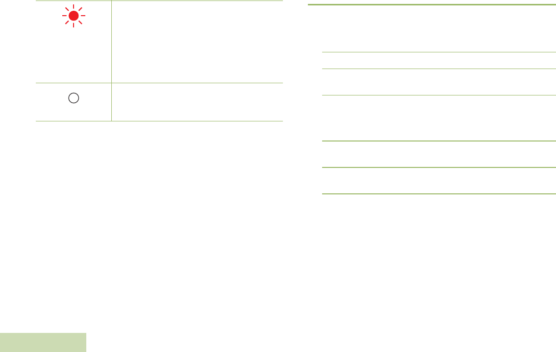
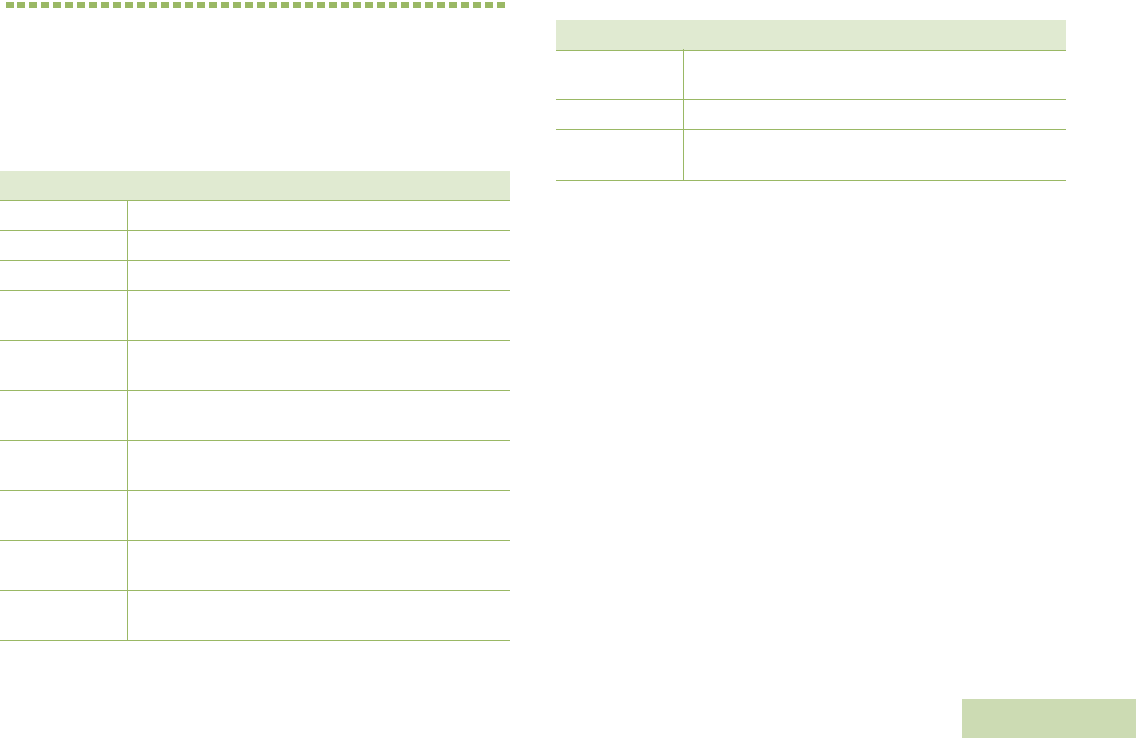
Table 4.3: Charging Status
LED Indication Charger State
Steady Green
Charged at least 95%
Steady Red
Rapid charge
Single Flash Green
Charged successfully powered up and is ready
for use
Slow Flash Green
Nearly charged at least 90%
Slow Flash Amber
Battery under voltage recovery
OR
Battery temperature is either too hot or too cold
– Wait to charge
If battery temperature is within operating
temperature, there may be a fault connection
– DO NOT charge battery
VEHICULAR CHARGER PMLN6716_
English
30
Troubleshooting
If There is Fast Flash Red Indication:
1Confirm the battery being used with the WRSM is listed in Table 4.1
and is good in condition.
2Remove the battery and restart the Vehicular Charger.
3If the symptom persist, please send the Vehicular Charger to the
nearest Service Center for further verification.
If There is No LED Indication:
1Check that the WRSM with battery or the battery is inserted
correctly in the pocket.
2Make sure that the CLA adapter is plugged into a CLA power
source and the LED on the CLA adapter is on.
3Confirm that the battery being used with the WRSM is listed in
Table 4.1 .
Fast Flash Red
Battery under voltage recovery time out
OR
Loss of charge current control
OR
Excessive power supply voltage
OR
Fault connection happened
– DO NOT charge battery
Off
If battery is inserted into a successfully powered
up charger, battery may have bad contact with
charger
Table 4.3: Charging Status (Continued)
REPLACEABLE PARTS
English
31
CHAPTER 5: REPLACEABLE PARTS
Other than the replaceable parts listed below, the PMMN4096_,
PMLN6714_ and PMLN6716_ are not repairable.
The following parts are available:
* Charger only UL approved when shipped with this power supply.
(Applicable for North America region only)
Table 5.1: Replaceable Parts
Part Number Description
PMLN6743_ Swivel Clip
42009312001 D-Ring Swivel Clip
PMNN4461_ Battery Standard Li-Ion 1750M1800T
25012022001* Power Supply, Charger Switch Mode, 110 – 240 V
US/NA/JPN/TAIWAN
25012022002 Power Supply, Charger Switch Mode, 110 – 240 V
EURO
25012022003 Power Supply, Charger Switch Mode, 110 – 240 V
UK
25012022004 Power Supply, Charger Switch Mode, 110 – 240 V
CHINA
25012022006 Power Supply, Charger Switch Mode, 110 – 240 V
AUS/NZ
25012022007 Power Supply, Charger Switch Mode, 110 – 240 V
BRZ
25012022008 Power Supply, Charger Switch Mode, 110 – 240 V
ARG
25012022009 Power Supply, Charger Switch Mode, 110 – 240 V
KOR
HLN9073_ Microphone Hang-up Clip
KT-SB1X-
LANYD3 Standard Lanyard with Velcro
Table 5.1: Replaceable Parts (Continued)
Part Number Description

REPLACEABLE PARTS
English
32
NOTES

OPEN SOURCE SOFTWARE LEGAL NOTICE
English
33
CHAPTER 6: OPEN SOURCE
SOFTWARE LEGAL NOTICE
This Motorola Solutions Product contains Open Source Software. For
information regarding licenses, acknowledgments, required copyright
notices and other usage terms, refer to the documentation for this
Motorola Solutions Product at:
https://businessonline.motorolasolutions.com
Go to: Resource Center > Product Information > Manual >
Accessories > Remote Speaker Microphone

OPEN SOURCE SOFTWARE LEGAL NOTICE
English
34
NOTES
SERVICE AND SUPPORT
English
35
CHAPTER 7: SERVICE AND
SUPPORT
DO NOT disassemble the PMMN4096_, PMLN6714_ and PMLN6716_;
they are not repairable. Order replacement parts listed in
“REPLACEABLE PARTS" on page 41.
Please contact Motorola Solutions Customer Care as shown in
Table 7.1 below for ordering or any technical troubleshooting
assistance.
Table 7.1: Motorola Solutions Customer Care Phone Numbers
Regions Phone Number
US and Canada 1-800-927-2744
Latin America (5) 257-6700 or
(571) 602-1111
European
(Repair and Service Centre) +49-30-6686-1555
Asia
1-800-88-0089
(Contact your Motorola Dealer for
Support)

SERVICE AND SUPPORT
English
36
NOTES

WARRANTY
English
37
CHAPTER 9: WARRANTY
Contact your Motorola Solutions dealer for detailed information on the
standard warranty. The workmanship warranty guarantees against
defects in workmanship under normal use and service.
NOTE: Warranty is void after customer replacement of any parts
other than replacement parts listed.
Limited Warranty
MOTOROLA COMMUNICATION PRODUCTS
I. WHAT THIS WARRANTY COVERS AND FOR HOW LONG:
MOTOROLA SOLUTIONS, INC. (“MOTOROLA”) at its option, will at no
charge either repair the Product (with new or reconditioned parts),
replace it (with a new or reconditioned Product), or refund the purchase
price of the Product during the warranty period provided it is returned in
accordance with the terms of this warranty. Replaced parts or boards
are warranted for the balance of the original applicable warranty period.
All replaced parts of Product shall become the property of MOTOROLA.
This express limited warranty is extended by MOTOROLA to the
original end user purchaser only and is not assignable or transferable to
any other party. This is the complete warranty for the Product
manufactured by MOTOROLA. MOTOROLA assumes no obligations or
liability for additions or modifications to this warranty unless made in
writing and signed by an officer of MOTOROLA.
Unless made in a separate agreement between MOTOROLA and the
original end user purchaser, MOTOROLA does not warrant the
installation, maintenance or service of the Product.
MOTOROLA cannot be responsible in any way for any ancillary
equipment not furnished by MOTOROLA which is attached to or used in
connection with the Product, or for operation of the Product with any
ancillary equipment, and all such equipment is expressly excluded from
this warranty. Because each system which may use the Product is
unique, MOTOROLA disclaims liability for range, coverage, or operation
of the system as a whole under this warranty.
Table 9.1: Warranty Period
Name Year
Wireless Remote Speaker Microphone PMMN4096_ One (1) Year
Dual Unit Charger PMLN6714_ One (1) Year
Vehicular Charger PMLN6716_ One (1) Year
Wireless Remote Speaker Microphone Battery
PMNN4461_ One (1) Year

WARRANTY
English
38
II. GENERAL PROVISIONS:
This warranty sets forth the full extent of MOTOROLA’S responsibilities
regarding the Product. Repair, replacement or refund of the purchase
price, at MOTOROLA’s option, is the exclusive remedy. THIS
WARRANTY IS GIVEN IN LIEU OF ALL OTHER EXPRESS
WARRANTIES. IMPLIED WARRANTIES, INCLUDING WITHOUT
LIMITATION, IMPLIED WARRANTIES OF MERCHANTABILITY AND
FITNESS FOR A PARTICULAR PURPOSE, ARE LIMITED TO THE
DURATION OF THIS LIMITED WARRANTY. IN NO EVENT SHALL
MOTOROLA BE LIABLE FOR DAMAGES IN EXCESS OF THE
PURCHASE PRICE OF THE PRODUCT, FOR ANY LOSS OF USE,
LOSS OF TIME, INCONVENIENCE, COMMERCIAL LOSS, LOST
PROFITS OR SAVINGS OR OTHER INCIDENTAL, SPECIAL OR
CONSEQUENTIAL DAMAGES ARISING OUT OF THE USER OR
INABILITY TO USE SUCH PRODUCT, TO THE FULL EXTENT SUCH
MAY BE DISCLAIMED BY LAW.
III. STATE LAW RIGHTS:
SOME STATES DO NOT ALLOW THE EXCLUSION OR LIMITATION
OF INCIDENTAL OR CONSEQUENTIAL DAMAGES OR LIMITATION
ON HOW LONG AND IMPLIED WARRANTY LASTS, SO THE ABOVE
LIMITATION OR EXCLUSIONS MAY NOT APPLY.
This warranty gives specific legal rights, and there may be other rights
which may vary from state to state.
IV. HOW TO GET WARRANTY SERVICE:
You must provide proof of purchase (bearing the date of purchase and
Product item serial number) in order to receive warranty service and,
also, deliver or send the Product item, transportation and insurance
prepaid, to an authorized warranty service location. Warranty service
will be provided by MOTOROLA through one of its authorized warranty
service locations. If you first contact the company which sold you the
Product (e.g., dealer or communication service provider), it can facilitate
your obtaining warranty service. You can also call MOTOROLA at
1-800-927-2744 US/Canada.
V. WHAT THIS WARRANTY DOES NOT COVER
A Defects or damage resulting from use of the Product in other that its
normal and customary manner.
B Defects or damage from misuse, accident, water, or neglect.
C Defects or damage from improper testing, operation, maintenance,
installation, alteration, modification, or adjustment.
D A Product subjected to unauthorized Product modifications,
disassembles or repairs (including, without limitation, the addition to
the Product of non-MOTOROLA supplied equipment) which
adversely affect performance of the Product or interfere with
MOTOROLA’s normal warranty inspection and testing of the
Product to verify any warranty claim.
E Product which has had the serial number removed or made
illegible.
F Freight costs to the repair depot.
G A Product which, due to illegal or unauthorized alteration of the
software/firmware in the Product, does not function in accordance
with MOTOROLA’s published specifications or the FCC certification
labeling in effect for the Product at the time the Product was initially
distributed from MOTOROLA.
H Scratches or other cosmetic damage to Product surfaces that does
not affect the operation of the Product.
I Normal and customary wear and teat.

WARRANTY
English
39
VI. PATENT AND SOFTWARE PROVISIONS:
MOTOROLA will defend, at its own expense, any suit brought against
the end user purchaser to the extent that it is based on a claim that the
Product or parts infringe a United States patent, and MOTOROLA will
pay those costs and damages finally awarded against the end use
purchaser in any such suit which are attributable to any such claim, but
such defense and payments are conditioned on the following:
A That MOTOROLA will be notified promptly in writing by such
purchaser of any notice of such claim;
B That MOTOROLA will have sole control of the defense of such suit
and all negotiations for its settlement or compromise; and
C Should the Product or parts become, or in MOTOROLA’s opinion be
likely to become, the subject of a claim of infringement of a United
States patent, that such purchaser will permit MOTOROLA, at its
option and expense, either to produce for such purchaser the right
to continue using the Product or parts or to replace or modify the
same so that it becomes non-infringing or to grant such purchaser a
credit for the Product or parts as depreciated and accept its return.
The depreciation will be an equal amount per year over the lifetime
of the Product or parts as established by MOTOROLA.
MOTOROLA will have no liability with respect to any claim of patent
infringement which is based upon the combination of the Product or
parts furnished hereunder with software, apparatus or devices not
furnished by MOTOROLA, nor will MOTOROLA have any liability
for the use of ancillary equipment or software for furnished by
MOTOROLA which is attached to or used in connection with the
Product. The foregoing states the entire liability of MOTOROLA with
respect to infringement of patents by the Product or any parts
thereof.
Laws in the United States and other countries preserve for
MOTOROLA certain exclusive rights for copyrighted MOTOROLA
software such as the exclusive rights to reproduce in copies and
distribute copies of such MOTOROLA software. MOTOROLA
software may be used in only the Product in which the software was
originally embodied and such software in such Product may not be
replaced, copied, distributed, modified in any way, or used to
produce any derivative thereof. No other use including, without
limitation, alteration, modification, reproduction, distribution, or
reverse engineering of such MOTOROLA software or exercise of
rights in such MOTOROLA software permitted. No license is
granted by implication, estoppel or otherwise under MOTOROLA
patent rights or copyrights.
VII. GOVERNING LAW:
This Warranty is governed by the laws of the State of Illinois, U.S.A.
MOTOROLA, MOTO, MOTOROLA SOLUTIONS and
the Stylized M logo are trademarks or registered trademarks
of Motorola Trademark Holdings, LLC and are used under license.
All other trademarks are the property of their respective owners.
© 2016 Motorola Solutions, Inc. All rights reserved.

WARRANTY
English
40
NOTES
BackCover.fm Page 1 Wednesday, November 9, 2016 11:11 AM

m
MOTOROLA, MOTO, MOTOROLA SOLUTIONS and
the Stylized M logo are trademarks or registered trademarks
of Motorola Trademark Holdings, LLC and are used under license.
All other trademarks are the property of their respective owners.
© 2016 Motorola Solutions, Inc. All rights reserved.
*MN003432A01*
MN003432A01-AA
BackCover.fm Page 2 Wednesday, November 9, 2016 11:11 AM