Motorola Solutions 89FT7006 FLN3135A & FLN3134A User Manual Owner sManual800
Motorola Solutions, Inc. FLN3135A & FLN3134A Owner sManual800
Contents
- 1. User Card
- 2. User Card Manual
User Card Manual

Applicant: Motorola, Inc. FCC ID: AZ489FT7006
Exhibit 8
Exhibit 8
User Manual
User Manual MW 800 Display
28 PDF pages total, 22 numbered pages
Please find the information required by Part 15.19, 15.21 & 15.105 on
page 4 of this PDF file.
Note: The Item above follow this cover page
a
Owner’s Manual
MW 800
Display
68P02969C35-O
DRAFT March 06 2003
68P02969C35-O
@6802969C35@
Owner'sManual800.book Page 1 Tuesday, March 11, 2003 12:19 PM
Owner'sManual800.book Page 2 Tuesday, March 11, 2003 12:19 PM
MW-800 Display Owner’s Manual
COMPUTER SOFTWARE COPYRIGHTS
The Motorola products described in this instruction manual may include copyrighted Motorola computer programs stored
in semiconductor memories or other media. Laws in the United States and other countries preserve for Motorola certain
exclusive rights for copyrighted computer programs, including the exclusive right to copy or reproduce in any form the
copyrighted computer program. Accordingly, any copyrighted Motorola computer programs contained In the Motorola
products described in this instruction manual may not be copied or reproduced in any manner without the express written
permission of Motorola. Furthermore, the purchase of Motorola products shall not be deemed to grant either directly or by
implication, estoppel or otherwise, any license under the copyrights, patents or patent applications of Motorola, except for
the normal non-exclusive, royalty free license to use that arises by operation of law in the sale of a product.
EPS – 34440- B
This warranty applies within the fifty (50) United States, the District of Columbia and Canada.
LIMITED WARRANTY
MOTOROLA COMMUNICATION PRODUCTS
If the affected product is being purchased pursuant to a written Communications System Agreement signed by Motorola,
the warranty contained in that written agreement will apply. Otherwise, the following warranty applies.
I. WHAT THIS WARRANTY COVERS AND FOR HOW LONG:
Motorola Inc. or, if applicable, Motorola Canada Limited ("Motorola") warrants the Motorola manufactured radio com-
munications product, including original equipment crystal devices and channel elements ("Product"), against material
defects in material and workmanship under normal use and service for a period of One (1) Year from the date of ship-
ment.
Motorola, at its option, will at no charge either repair the Product (with new or reconditioned parts), replace it with the
same or equivalent Product (using new or reconditioned Product), or refund the purchase price of the Product during
the warranty period provided purchaser notifies Motorola according to the terms of this warranty. Repaired or replaced
Product is warranted for the balance of the original applicable warranty period. All replaced parts of the Product shall
become the property of Motorola.
This express limited warranty is extended by Motorola to the original end user purchaser purchasing the Product for
purposes of leasing or for commercial, industrial, or governmental use only, and is not assignable or transferable to any
other party. This is the complete warranty for the Product manufactured by Motorola. Motorola assumes no obliga-
tions or liability for additions or modifications to this warranty unless made in writing and signed by an officer of Motor-
ola. Unless made in a separate written agreement between Motorola and the original end user purchaser, Motorola
does not warrant the installation, maintenance or service of the Product.
Motorola cannot be responsible in any way for any ancillary equipment not furnished by Motorola which is attached to
or used in connection with the Product, or for operation of the Product with any ancillary equipment, and all such equip-
ment is expressly excluded from this warranty. Because each system which may use the Product is unique, Motorola
disclaims liability for range, coverage, or operation of the system as a whole under this warranty.
II. GENERAL PROVISIONS:
This warranty sets forth the full extent of Motorola’s responsibilities regarding the Product. Repair, replacement or
refund of the purchase price, at Motorola’s option, is the exclusive remedy. THIS WARRANTY IS GIVEN IN LIEU OF
ALL OTHER EXPRESS WARRANTIES. MOTOROLA DISCLAIMS ALL OTHER WARRANTIES OR CONDITIONS,
EXPRESS OR IMPLIED, INCLUDING THE IMPLIED WARRANTIES OR CONDITIONS OF MERCHANTABILITY AND
FITNESS FOR A PARTICULAR PURPOSE. IN NO EVENT SHALL MOTOROLA BE LIABLE FOR DAMAGES IN
EXCESS OF THE PURCHASE PRICE OF THE PRODUCT, FOR ANY LOSS OF USE, LOSS OF TIME, INCONVE-
NIENCE, COMMERCIAL LOSS, LOST PROFITS OR SAVINGS OR OTHER INCIDENTAL, SPECIAL, INDIRECT OR
CONSEQUENTIAL DAMAGES ARISING OUT OF THE USE OR INABILITY TO USE SUCH PRODUCT, TO THE
FULL EXTENT SUCH MAY BE DISCLAIMED BY LAW.
III. HOW TO GET WARRANTY SERVICE:
Purchaser must notify Motorola’s representative or call Motorola’s Customer Response Center at 1-800-247-2346
within the applicable warranty period for information regarding warranty service.
IV. WHAT THIS WARRANTY DOES NOT COVER:
A) Defects or damage resulting from use of the Product in other than its normal and customary manner.
B) Defects or damage from misuse, accident, water, or neglect.
C) Defects or damage from improper testing, operation, maintenance, installation, alteration, modification, or adjustment.
D) Breakage or damage to antennas unless caused directly by defects in material workmanship.
E) A Product subjected to unauthorized Product modifications, disassemblies or repairs (including, without limitation, the
addition to the Product of non-Motorola supplied equipment) which adversely affect performance of the Product or
interfere with Motorola’s normal warranty inspection and testing of the Product to verify any warranty claim.
F) Product which has had the serial number removed or made illegible.
Owner'sManual800.book Page 3 Tuesday, March 11, 2003 12:19 PM
MW-800 Display Owner’s Manual
G) Batteries (they carry their own separate limited warranty).
H) Freight costs to the repair depot.
I) A Product which, due to illegal or unauthorized alteration of the software/firmware in the Product, does not function in
accordance with Motorola’s published specifications or with the FCC type acceptance labeling in effect for the Product
at the time the Product was initially distributed from Motorola.
J) Scratches or other cosmetic damage to Product surfaces that do not affect the operation of the Product.
K) That the software in the Product will meet the purchaser’s requirements or that the operation of the software will be
uninterrupted or error-free.
L) Normal and customary wear and tear.
M) Non-Motorola manufactured equipment unless bearing a Motorola Part Number in the form of an alpha numeric num-
ber (i.e., TDE6030B).
V. GOVERNING LAW
In the case of a Product sold in the United States and Canada, this Warranty is governed by the laws of the State of Illi-
nois and the Province of Ontario, respectively.
VI. PATENT AND SOFTWARE PROVISIONS:
Motorola will defend, at its own expense, any suit brought against the end user purchaser to the extent that it is based
on a claim that the Product or its parts infringe a United States patent, and Motorola will pay those costs and damages
finally awarded against the end user purchaser in any such suit which are attributable to any such claim, but such
defense and payments are conditioned on the following:
A) that Motorola will be notified promptly in writing by such purchaser of any notice of such claim;
B) that Motorola will have sole control of the defense of such suit and all negotiations for its settlement or compromise;
and
C) should the Product or its parts become, or in Motorola's opinion be likely to become, the subject of a claim of infringe-
ment of a United States patent, that such purchaser will permit Motorola, at its option and expense, either to procure for
such purchaser the right to continue using the Product or its parts or to replace or modify the same so that it becomes
non-infringing or to grant such purchaser a credit for the Product or its parts as depreciated and accept its return. The
depreciation will be an equal amount per year over the lifetime of the Product or its parts as established by Motorola.
Motorola will have no liability with respect to any claim of patent infringement which is based upon the combination of
the Product or its parts furnished hereunder with software, apparatus or devices not furnished by Motorola, nor will
Motorola have any liability for the use of ancillary equipment or software not furnished by Motorola which is attached to
or used in connection with the Product. The foregoing states the entire liability of Motorola with respect to infringement
of patents by the Product or any of its parts thereof.
Laws in the United States and other countries preserve for Motorola certain exclusive rights for copyrighted Motorola
software such as the exclusive rights to reproduce in copies and distribute copies of such Motorola software. Motorola
software may be used only in the Product in which the software was originally embodied and such software in such
Product may not be replaced, copied, distributed, modified in any way, or used to produce any derivative thereof. No
other use including, without limitation, alteration, modification, reproduction, distribution, or reverse engineering of such
Motorola software or exercise of rights in such Motorola software is permitted. No license is granted by implication,
estoppel or otherwise under Motorola patent rights or copyrights.
EPS – 48759 – O
FCC INTERFERENCE WARNING
The FCC requires that manuals pertaining to Class A and Class B computing devices must contain warnings about possi-
ble interference with local residential radio and TV reception. This warning reads as follows:
NOTE: This equipment has been tested and found to comply with limits for a Class B digital device, pursuant to Part 15 of
the FCC Rules. These limits are designed to provide reasonable protection against harmful interference when the equip-
ment is operated in a commercial or residential environment. This equipment generates, uses, and can radiate radio fre-
quency energy and, if not installed and used in accordance with the instruction manual, may cause harmful interference to
radio communications.
This device complies with Part 15 of the FCC Rules. Operation is subject to the following two conditions:
(1) This device may not cause harmful interference.
(2) This device must accept any interference received, including interference that may cause undesired operation.
Caution: Changes or modifications made in the radio terminal, not expressly approved by Motorola, will void the user's
authority to operate the equipment.
SAFE USAGE
For product safety of the MW 800 Display installed in vehicles, refer to safety leaflet, Motorola publication Number
68P029xxCxx.
Owner'sManual800.book Page 4 Tuesday, March 11, 2003 12:19 PM
5
Trademarks
Motorola and the Motorola logo are registered trademarks of Motorola Inc.
Microsoft, MS-DOS, MS-Windows, and Windows are registered trademarks of Microsoft Corporation.
Adobe and Acrobat are registered trademarks of Adobe Systems Incorporated.
Owner'sManual800.book Page 5 Tuesday, March 11, 2003 12:19 PM
MW-800 Display Owner’s Manual
Owner'sManual800.book Page 6 Tuesday, March 11, 2003 12:19 PM

68P02969C35-O
© Motorola Inc., 2003 March, 2003
Contents
Commercial, Government and Industrial Solutions Sector
1301 E. Algonquin Road, Schaumburg, IL 60196
Using this Manual ......................................................................... 3
Who Should Use this Manual ................................................................... 3
What is in this Manual .............................................................................. 3
Safe Handling Instructions........................................................................ 3
Notational Conventions .............................................................................. 3
Operational Warnings ................................................................................. 4
Display Unit Overview.................................................................. 7
Display Features ......................................................................................... 7
Display Buttons........................................................................................... 8
Display Indicators....................................................................................... 9
Speakers .................................................................................................... 10
Touchscreen .............................................................................................. 10
Display Connections ................................................................................. 11
Standard Display Cable Adaptor .............................................................. 12
MW 800 Display Installation.................................................................... 12
Operating the MW 800 Display................................................. 13
Powering On ........................................................................................... 13
Powering Off........................................................................................... 13
Adjusting the LCD Display .................................................................... 14
Powering On in Extreme Temperature Conditions................................. 14
XGA Display Option ................................................................................ 14
SVGA Display Option .............................................................................. 15
Operating in Extreme Temperature Conditions...................................... 15
XGA Display Option ................................................................................ 15
SVGA Display Option .............................................................................. 16
Owner'sManual800.book Page i Tuesday, March 11, 2003 12:19 PM
ii Contents
Operating with a Discharged Vehicle Battery ........................................ 16
XGA Display Option ................................................................................ 16
SVGA Display Option .............................................................................. 16
Screen Calibration ...................................................................... 16
Maintenance ................................................................................ 17
Cleaning the MW 800 Display ............................................................... 17
.................................................................................................................. 17
Cleaning the Display................................................................................. 17
Tips for Using the MW 800 Display .......................................... 17
Appendix A: Approved Accessories.......................................... 20
INDEX.......................................................................................... 21
Owner'sManual800.book Page ii Tuesday, March 11, 2003 12:19 PM

Using this Manual 3
Using this Manual
Who Should Use this Manual
This manual is intended for staff who operat the MW 800 Display
MW 800 Display in a vehicle.
What is in this Manual
This manual lists the features of the MW 800 Display vehicle and
provide description of the MW 800 Display hardware components
and operating instructions. The manual also provide user level
maintenance and troubleshooting directions.
Safe Handling Instructions
Notational Conventions
Throughout this publication, you will notice the use of warnings,
cautions, and notes. These notations are used to emphasize that
safety hazards exist, and care must be taken.
Do not proceed beyond WARNING or CAUTION until the indicated
conditions are fully understood and met.
WARNING
.
CAUTION
Indicates a potentially hazardous situation which, if
not avoided, COULD result in death or serious injury.
!
Warning
Indicates a potentially hazardous situation which, if not
avoided, MAY result in minor or moderate injury.
CAUTION may also be used to alert against unsafe
practices and property-damage-only accident hazards.
!
Caution
Owner'sManual800.book Page 3 Tuesday, March 11, 2003 12:19 PM
4 MW 800 Display Owner’s Manual
NOTE
Operational Warnings
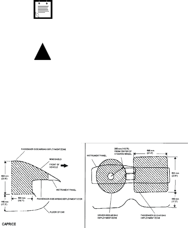
Provided for your reference are several air bag deployment zone
template from an automobile used in public safety roles (Figure 1
Please obtain the official documents for the automobile in
which you are installing the MW 800 Display to ensure the safety of
the operator.
.
An operational procedure, practice, condition, etc., which
it is essential to emphasize.
Note
For Vehicles With an Air Bag
Do not place a portable radio in the area over an air
bag or in the air bag deployment area. Air bags inflate
with great force. If a portable radio terminal is placed
in the air bag deployment area and the air bag inflates,
the radio terminal may be propelled with great force
and cause serious injury to occupants of the vehicle.
Owner'sManual800.book Page 4 Tuesday, March 11, 2003 12:19 PM
.
.
Figure 1
Air Bag Deployment Zones - Caprice
!
Warning

Owner'sManual800.book Page 5 Tuesday, March 11, 2003 12:19 PM
Using the Manual 5
6 MW 800 Display Owner’s Manual
Owner'sManual800.book Page 6 Tuesday, March 11, 2003 12:19 PM

Display Unit Overview 7
Display Unit Overview
Display Features
Standard hardware features include:
• 12.1", 1024 × 768, XGA color, high brightness (1200 nit) LCD or
12.1", 800 × 600, SVGA color, standard brightness (350 nit) LCD
• Touch Screen with anti rflection and better transitivity
• Two USB Connectors used for keyboard and general purpose
(Note that all full-speed USB devices must be connected directly
to the USB port on the workstation)
• Brightness is manually adjustable, sunlight visible at high level
and night light dim at low level
• Smart thermal management in extreme high or low temperatures
• A backlight heater for low temperatures
• Bluetooth radio connection option
• Eight software controled function keys
• Volume control
• Workstation On/Off button
• On Screen Display (OSD) calibration
• Emergency button
Owner'sManual800.book Page 7 Tuesday, March 11, 2003 12:19 PM
8 MW 800 Display Owner’s Manual
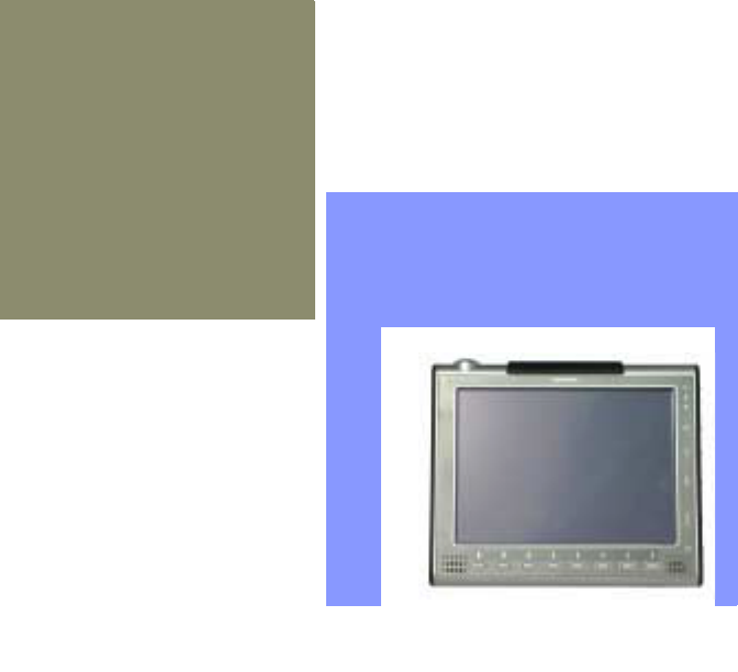
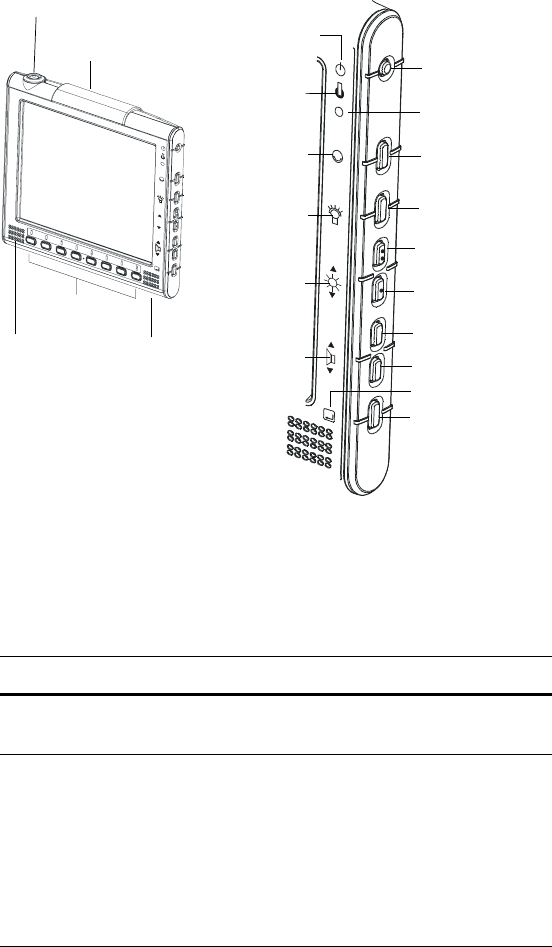
The following figure shows the front view of the display unit:.
Display Buttons
The display unit comprises the following buttons:
Figure 4
Color Display Unit
Workstation
Power Indicator
Workstation Power
Temperature
out of range
indicator
??????
Suspend \ resume
Backlight
Increase Volume
Decrease Volume
RGB Indicator
OSD Calibration
Suspend
Indicator
Backlight
Indicator
Screen
Brightness
Indicator
Volume
Indicator
Increase Screen
Brightness
Decrease Screen
Brightness
Emergency button
Function
Keys
Left
Speaker
Right
Speaker
Bluetooth Antenna
Button Description
Workstation Power To turn the MW 800 Display Workstation on
or off
Suspend/
Resume
To toggle the MW 800 Display between
Suspend and Resume modes. When in
Suspend mode, the display and computer
sections are turned off. The workstation
enters a power saving mode.
When the MW 800 Display resumes, it
returns to the state it was prior to suspend
(previous display, LED indications, etc.)
Owner'sManual800.book Page 8 Tuesday, March 11, 2003 12:19 PM

Display Unit Overview 9
Display Indicators
The indicator LEDs located on the display unit show the MW 800
Display status, as described in the following table:
Backlight To toggle between backlight on and off. Set
the desired backlight brightness, using the
Brightness button
Brightness Tap the upper arrow to increase or the lower
arrow to decrease the on-screen light level.
You may tap up to 32 continuous linear
brightness levels.
You can control the brightness only if the
backlight is turned on (Backlight LED is off)
Volume Tap the upper arrow to increase or the lower
arrow to decrease the speaker’s volume
level. You may tap up to 64 continuous linear
volume levels
User-defined To carry out specific functions, depending on
specific user application
Emergency To send an emergency message to the RF
host computer. The Emergency button will
be functional as soon as you power the
workstation.
(This key functionality depends on the
definition given by each user system and the
active application)
Button Description
LED Description
Power
(green)
On:
Blinking:
Off:
System is on.
The vehicle battery is discharged.
System is off, or the terminal is in
Suspend mode
Temperature
(red)
Blinking:
Off:
CPU or display unit temperature is
out of range. For more information,
refer to “Powering On in Extreme
Temperature Conditions”, on
page 14
Normal operation
Owner'sManual800.book Page 9 Tuesday, March 11, 2003 12:19 PM
10 MW 800 Display Owner’s Manual
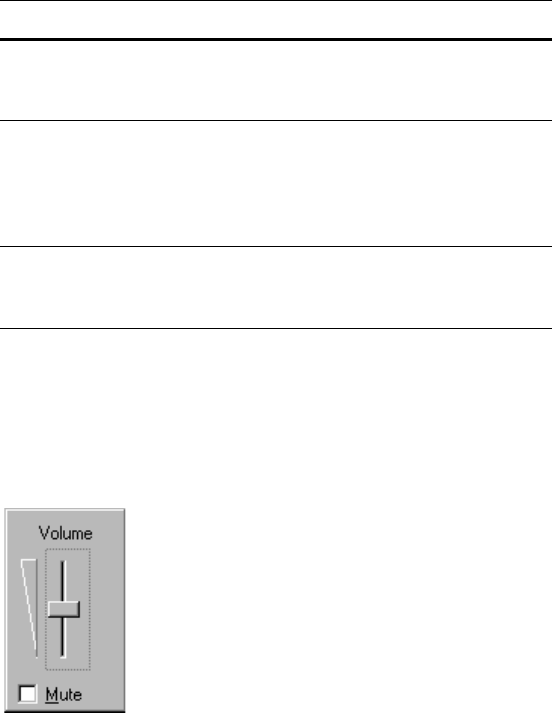
Speakers
The speakers are used for user audio (Mono/Stereo) and alert
signaling. Adjust the speaker volume with the Volume button. To set
the audio level, open the speaker volume bar by pressing the speaker
icon on the lower Tool Bar. The volume bar appears on the screen.
.
The new volume setting is saved in the memory.
Touchscreen
The resistive touchscreen is sealed against moisture and dirt and can
be operated with gloved hands. For detailed information on the
Suspend/
Resume
(green)
On:
Off:
System is in Suspend mode
Normal operation
Backlight
(green)
On:
Blinking:
Off:
LCD backlight is off
Ignore this information
LCD backlight is on
RGB
(green)
On:
Off:
Valid RGB signal from CPU
NO valid RGB signal from CPU
LED Description
Figure 5
Volume Bar
Owner'sManual800.book Page 10 Tuesday, March 11, 2003 12:19 PM
Display Unit Overview 11
touchscreen calibration, see “Calibrating the Touchscreen”, on
page 48.
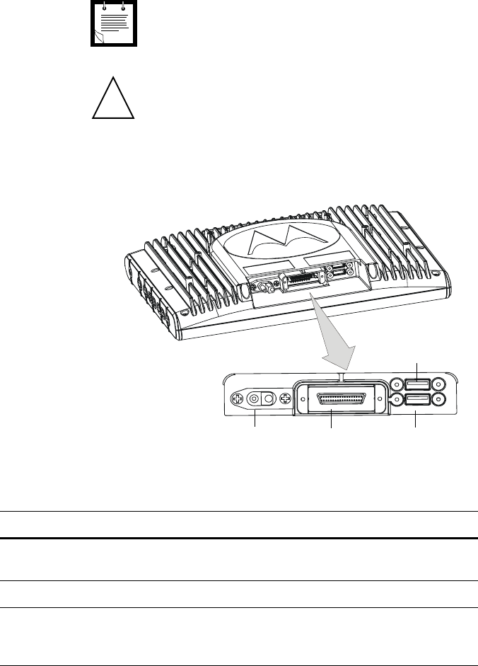
Display Connections
The rear panel of the display shows the following connectors:
Figure 6
Display - Connectors
A screen saver should be used.
Do not display a single image on screen for an extended
period of time.
Note
!
Caution
Display Power Display In USB Port 2
USB Port 1
Connector Description
Display Power DC connector for vehicle. Requires a standard Motorola
power cable with 15 A fuse
Display In RGB, USB and Sound from workstation
USB 1 & USB 2 Ports USB 1 to Keyboard and USB 2 to any peripheral device.
(Note that all full-speed USB devices must be connected
directly to the USB port, on the workstation)
Owner'sManual800.book Page 11 Tuesday, March 11, 2003 12:19 PM
12 MW 800 Display Owner’s Manual
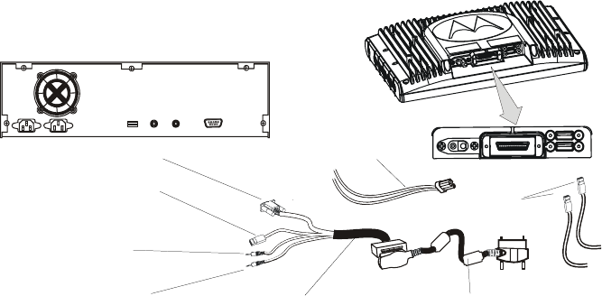
Standard Display Cable Adaptor
The standard display cable adaptor enables to interface any standard
screen to the workstation. The adapter connects to the Display-CPU
cable.
The standard display cable adaptor is shown in the figure below
Figure 7
Standard Display Cable Adaptor
MW 800 Display Installation
The MW 800 display is attached to any display mount by Phillips
screws, supplied in the display shipping carton. The display cable
from the workstation is routed through the mount and connected to
the lower back side of the display. Use caution when assembling the
cable to the display to prevent damage to the display or the cable.
All display options have an additional power cable that must be used
to supply power to the display. The display Power cable must be
protected by 15A fuse.
RGB Connector
USB Connector
Speaker
Connector
Mic Connector
Cable Adaptor Display Cable
Power Cable
USB Cables
Owner'sManual800.book Page 12 Tuesday, March 11, 2003 12:19 PM
Operating the MW 800 Display 13
Operating the MW 800 Display
Powering On
Before powering the MW 800 Display:
• Verify that the Display to PC cable is connected on both sides.
• Verify that the keyboard USB wire is connected to the display.
• Verify that the vehicle power system can supply at least 15 A.
• Check that the power cables are plugged into the DC connectors of
the display.
• Switch on the PC power switch .
If the MW 800 Display is ignition-sensitive, insert the car key into
the ignition switch and rotate it to ACC position, or start the engine,
before powering on.
To power the workstation, press the Power button on the front panel
of the CPU box, or press the Workstation Power button on the
display. Upon power up, the display power and OSD indicators are
lit, indicating that the system is on and the display is properly
connected to the CPU box.
Powering Off
To turn the workstation, press the CPU box Power button
momentarily, the workstation will shut-down. Remember to save
important information before turning off the MW 800 Display.
The MW 800 Display automatically turns off as a result of:
• Extreme temperatures.
• Discharged vehicle battery.
• Pressing the Power button on the display for more than 3 seconds.
In critical conditions, the workstation may be powered off by turning
Off the main power switch on the CPU box back panel.
The main power switch of the PC must be in OFF position
when the system is connected to a power supply.
Note
Owner'sManual800.book Page 13 Tuesday, March 11, 2003 12:19 PM

14 MW 800 Display Owner’s Manual
.
If the MW 800 Display is ignition-sensitive, it turns off automatically
when the engine is switched off. However, you can return the car key
to ACC position and resume working, if required.
Adjusting the LCD Display
The MW 800 Display incorporates a transmissive color Thin Film
Transistor (TFT). The screen provides the best possible readability in
the lighting conditions typically found in the vehicle environment.
The MW 800 Display is shipped with color palette settings that have
been optimized for operation in the vehicle. The appearance of the
screen can be changed by pressing the On Screen Display (OSD)
button, on the display, and using the OSD application.
The brightness of the display is affected by the settings of the
brightness control of the color palette.
Adjustment of the color palette in Windows XP can be made in the
Control Panel under the Appearance tab of the “Display” section.
Best results are obtained using the “OSD” application scheme.
Powering On in Extreme Temperature Conditions
XGA Display Option
The MW 800 Display operating temperature range is -4 to +131°F (-
20°C - +50°C).
.
When powering on below the operating temperature range, the
temperature LED blinks. The workstation will automatically power
up once the operating temperature range is reached (the internal
Turning off the main power switch or disconnecting the
power cable when the MW 800 Display is running may
seriously damage your operating system or your hard
disk.
!
Caution
To enable the full operating temperature range, the BIOS
setup Idle Mode parameter must be set to its default
value.
!
Caution
Owner'sManual800.book Page 14 Tuesday, March 11, 2003 12:19 PM
Operating the MW 800 Display 15
heater will raise the MW 800 Display temperature to within its
operating range). You may also turn the workstation off and try again
at a later stage.
In extreme temperatures above +122°F (50°C), the workstation will
not power up.
SVGA Display Option
If the ambient temperature is in the +122 to +167°F (+50°C - +75°C)
range, the temperature LED will blink and the MW 800 Display will
power up, but the display brightness level will be approximately one
third of the maximum level. If the temperature drops to the operating
range the display brightness will be restored.
If the ambient temperature is in the -4 to +32°F (-20°C - 0°C) range,
the temperature LED will blink and the backlight heater will start
operating. When the CCFL (Cold Cathode Fluorescent Lamps)
temperature reaches +32°F (0°C) (after approximately 2 minutes) the
MW-800 will automatically turn on.
If the ambient temperature is in the +30 to +68°F (0°C - +20°C)
range, the backlight heater will operate and the MW 800 Display will
turn on at once. The heater turns off when the CCFL temperature
reaches 122°F (50°C).
Operating in Extreme Temperature Conditions
XGA Display Option
If, during normal operation, the ambient temperature deviates from
the normal operating range, the temperature LED will blink. When
the temperature returns to within the operating temperature range, the
LED will be turned off.
A special temperature management mechanism prevents the
MW-800 from reaching extreme hot or cold temperatures. This is
achieved using a clock throttling technique and an internal heater.
Owner'sManual800.book Page 15 Tuesday, March 11, 2003 12:19 PM

16 MW 800 Display Owner’s Manual
SVGA Display Option
If during normal operation, the ambient temperature is higher than
the normal operating range the temperature LED will blink, the
display brightness level will be approximately one third of the
maximum level, and a warning message will be displayed on the
screen. When the LCD temperature sensor approaches +167°F
(+75°C), the MW 800 Display will automatically power off after 3
minutes.
If the ambient temperature drops to the normal operating range, the
display brightness will be automatically restored.
Operating with a Discharged Vehicle Battery
XGA Display Option
If, during normal operation, the vehicle battery voltage drops to
10.2V, the power status LED will blink and a warning message will
be displayed on the screen. If the voltage continues to drop, the
MW-800 will automatically power off at 8.5V.
SVGA Display Option
During power cranking, the display backlight is automatically turned
off at 8V to save power. The backlight will be restored once the
vehicle battery voltage is a stable 10.4V for at least 4 seconds.
Screen Calibration
To calibrate the screen, do the following:
1. Press the OSD calibration button, located on the lower right hand
side of the display. The OSD application dialog box is displayed.
2. Use the calibration buttons and follow the instructions on the
screen.
Owner'sManual800.book Page 16 Tuesday, March 11, 2003 12:19 PM

Maintenance 17
Maintenance
Cleaning the MW 800 Display
The MW 800 Display is designed to operate well in typical field
conditions. Simple routine maintenance can extend the life of the
unit, ensuring continued dependability.
Cleaning the Display
The LCD has a polarized surface and can be damaged easily. To
prevent damage:
• Do not get liquids on the screen.
• Do not use water, window cleaner, acetone, aromatic solvent or
dry, rough towels to clean the screen.
To clean the LCD, use a soft cloth with ethyl or rubbing (isopropyl)
alcohol. Wipe the screen lightly.
Turn your equipment off if you accidentally:
• Expose the LCD to liquid.
• Drop, jar or damage the LCD.
Call a service technician if either of these instances occur.
Tips for Using the MW 800 Display
This information will help you avoid potential problems when you
use the MW 800 Display.
• Follow all the instructions and cautions in your MW 800 Display
user documentation.
• Do not disassemble the MW 800 Display. Opening the display
voids your warranty.
• The MW 800 Display automatically shuts off when the system
temperature rises above 140°F (60°C). General Specifications
Owner'sManual800.book Page 17 Tuesday, March 11, 2003 12:19 PM

18 MW 800 Display Owner’s Manual
LCD XGA SVGA
Size 12.1” 12.1”
Resolution: 800 x 600 1024 x 768
Colors: 256,000 colors 256,000 colors
Type: 5 wire resistive 5 wire resistive
Brightness: Standard 350 nit High-bright 1200 nit
Communications/Expansion
USB 2 internal and 2 external
ports
Display Keys: 8 illuminated function keys
Control Keys: 8 control keys
Radio Communications
Bluetooth Radio Class 2, 2.402-2.480 GHz
ISM band
Housing
Display Size: 12.1 x 12 x 2 (26.7 x 30.5 x 5.1 cm)
Environmental
Operating Temperature -20° to +50°C
Storage Temperature -40° to +70°C
Humidity 90% to 95% non condensing @ 50°C
Vibration Per MIL STD 810E
Specifications subject to change without notice.
Owner'sManual800.book Page 18 Tuesday, March 11, 2003 12:19 PM
Tips for Using the MW 800 Display 19
Owner'sManual800.book Page 19 Tuesday, March 11, 2003 12:19 PM

20 MW 800 Display Owner’s Manual
Appendix A: Approved Accessories
Table 1
MW-800 Display Approved Accessories
Accessory Part No. Remarks
DISPLAY-CPU Cable
4.5FT (1.5M)
FKN8068
DISPLAY-CPU Cable
9.6FT (3.2M)
FKN8069
DISPLAY-CPU Cable
17FT (5.6M)
FKN8070
Display DC Cable FKN4711
DISPLAY Y CABLE FKN8090 Standard display cable adapter
Owner'sManual800.book Page 20 Tuesday, March 11, 2003 12:19 PM

INDEX
A
approved accessories 20
B
Backlight
button 9
LED 10
BIOS 17
Brightness button 9
C
color display 8
E
Emergency button 9
extreme temperature conditions 14
I
ignition-sensitive 14
indicators 9
L
LCD
brightness 14
contrast 14
O
operating system 14
operating temperature range 14
P
Power button 8
Power LED 9
S
speaker 10
Suspend/Resume
button 8
LED 10
System BIOS 17
T
Temperature LED 9
touchscreen 10
Owner'sManual800.book Page 21 Tuesday, March 11, 2003 12:19 PM