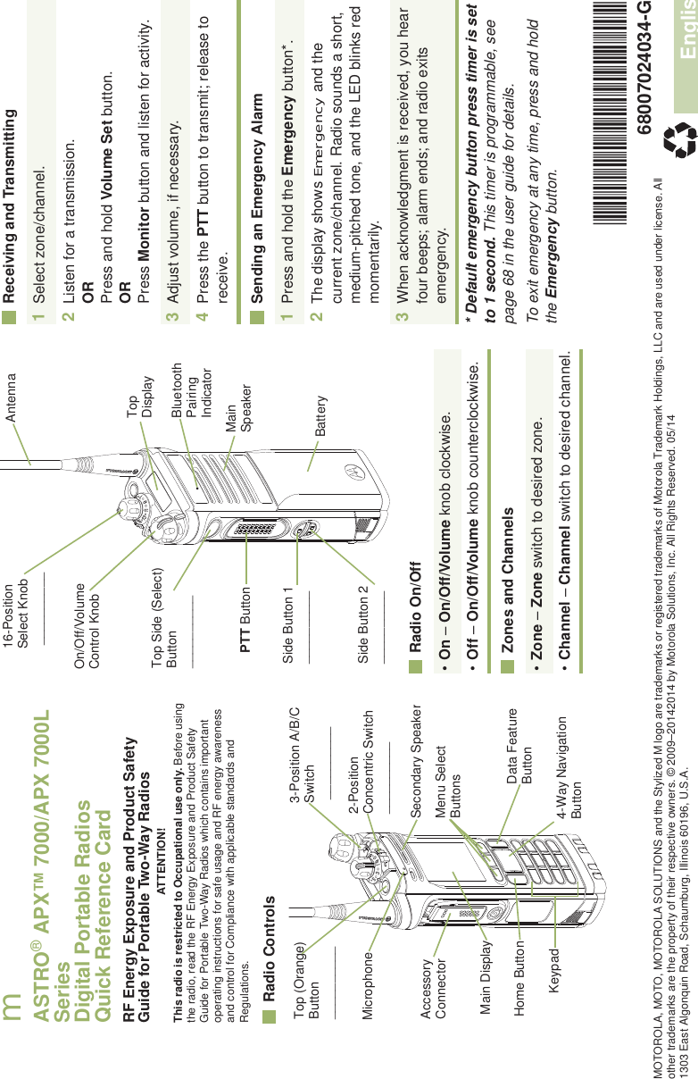
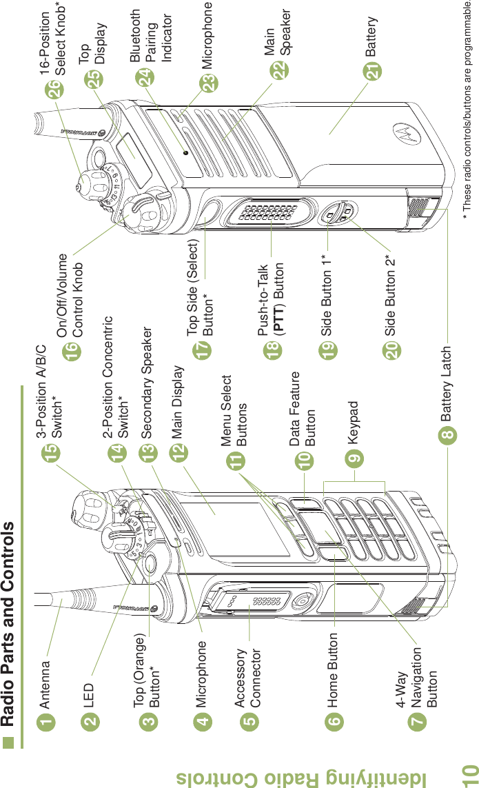
Motorola Solutions 89FT7059 Portable 2-way radio User Manual APX 7000 7000L Portable Dual Display User Guide
Motorola Solutions, Inc. Portable 2-way radio APX 7000 7000L Portable Dual Display User Guide
Contents
- 1. Safety Manual
- 2. User Manual
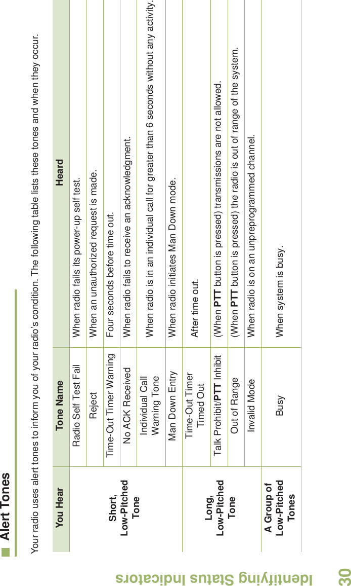
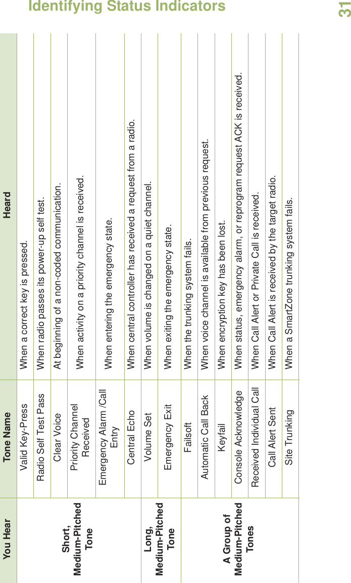
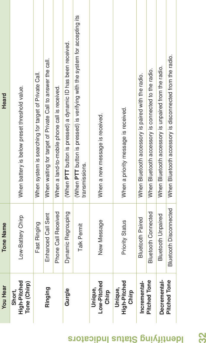
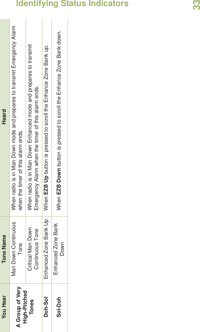
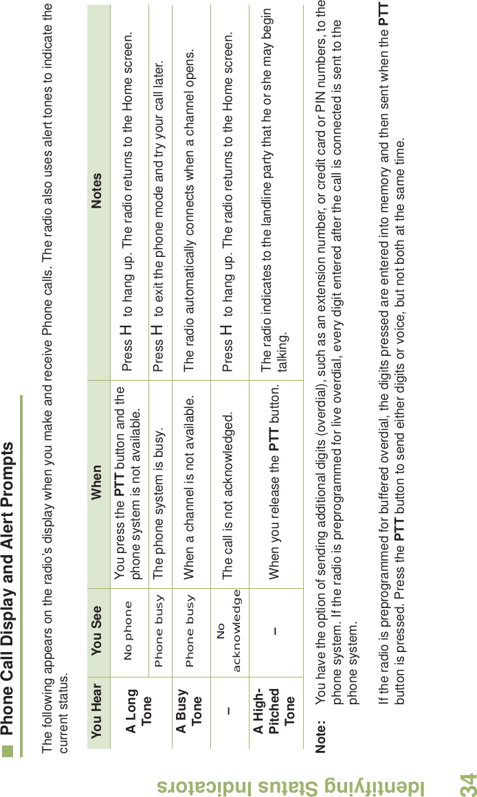
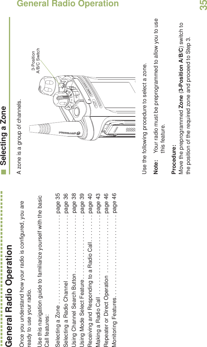
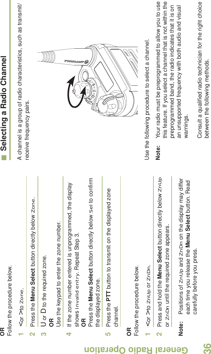
User Manual