Motorola Solutions 89FT7069 Portable 2-Way Radio User Manual Manual
Motorola Solutions, Inc. Portable 2-Way Radio Manual
Contents
- 1. Manual
- 2. RF Safety Manual
Manual
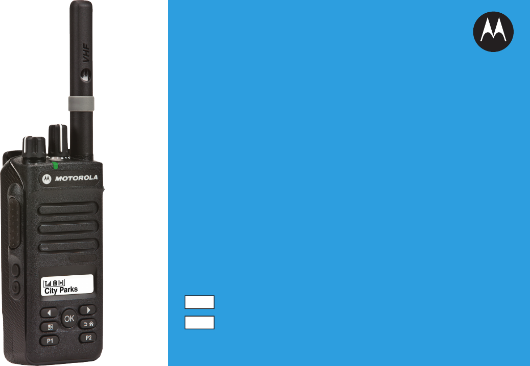
PROFESSIONAL DIGITAL TWO-WAY RADIO
MOTOTRBOMC
XPR 3500/XPR 3500e
LIMITED KEYPAD PORTABLE
PORTATIVES AVEC CLAVIER LIMITÉ
USER GUIDE
GUIDE DE L’UTILISATEUR
fr-CA
en

Contents
Declaration of Conformity......................... 6
Important Safety Information..........8
Software Version..............................9
Computer Software Copyrights....10
Handling Precautions.................... 11
Getting Started............................... 12
How to Use This Guide..................................12
What Your Dealer/System Administrator
Can Tell You.............................................12
Preparing Your Radio for Use.......13
Charging the Battery......................................13
Attaching the Battery..................................... 13
Attaching the Antenna................................... 14
Attaching the Belt Clip................................... 15
Attaching the Universal Connector Cover
(Dust Cover)............................................. 15
Attaching the Accessory Connector...............16
Powering Up the Radio..................................17
Adjusting the Volume.....................................18
Identifying Radio Controls............ 19
Radio Controls...............................................19
Programmable Buttons..................................20
Assignable Radio Functions............... 20
Assignable Settings or Utility
Functions....................................... 22
Accessing the Programmed Functions..........22
Push-To-Talk (PTT) Button............................23
Switching Between Conventional Analog
and Digital Mode.......................................24
IP Site Connect..............................................25
Capacity Plus.................................................25
Contents
1
English

Linked Capacity Plus..................................... 26
Identifying Status Indicators.........28
Display Icons................................................. 28
Call Icons.......................................................30
Advanced Menu Icons................................... 31
Mini Notice Icons........................................... 31
Sent Item Icons ......................................... 31
LED Indicator.................................................31
Alert Tones.................................................... 33
Indicator Tones..............................................33
Making and Receiving Calls..........34
Selecting a Zone............................................34
Selecting a Channel.......................................34
Receiving and Responding to a Radio Call... 35
Receiving and Responding to a
Group Call......................................35
Receiving and Responding to a
Private Call ................................ 36
Receiving an All Call ..........................37
Receiving and Responding to a
Selective Call .............................37
Making a Radio Call............................38
Making a Radio Call.......................................41
Making a Group Call........................... 42
Making a Private Call ......................42
Making an All Call .............................. 43
Making a Selective Call .................. 44
Stopping a Radio Call ................................45
Talkaround.....................................................45
Monitoring Features.......................................46
Monitoring a Channel..........................46
Permanent Monitor............................. 46
Advanced Features........................48
Radio Check.................................................. 48
Sending a Radio Check...................... 48
Scan Lists...................................................... 48
Viewing an Entry in the Scan List....... 49
Editing the Scan List........................... 49
Scan...............................................................51
Starting and Stopping Scan................ 51
Responding to a Transmission
During a Scan................................ 52
Deleting a Nuisance Channel............. 52
Restoring a Nuisance Channel........... 53
Vote Scan ..................................................53
Contact Settings............................................ 53
Contents
2
English

Making a Group Call from Contacts....54
Making a Private Call from
Contacts .................................... 55
Setting a Default Contact ................55
Call Indicator Settings....................................56
Activating and Deactivating Call
Ringers for Call Alert ................. 56
Activating and Deactivating Call
Ringers for Private Calls ............57
Activating and Deactivating Call
Ringers for Selective Call .......... 57
Assigning Ring Styles......................... 58
Selecting a Ring Alert Type................ 58
Configuring Vibrate Style.................... 59
Escalating Alarm Tone Volume...........60
Call Log Features.......................................... 60
Viewing Recent Calls..........................60
Deleting a Call from a Call List............61
Viewing Details from a Call List.......... 61
Call Alert Operation....................................... 62
Receiving and Responding to a
Call Alert........................................ 62
Making a Call Alert from the
Contact List....................................62
Making a Call Alert with the One
Touch Access Button.....................63
Emergency Operation....................................63
Sending an Emergency Alarm............ 64
Sending an Emergency Alarm with
Call.................................................65
Sending an Emergency Alarm with
Voice to Follow .......................... 66
Reinitiating an Emergency Mode........68
Exiting Emergency Mode After
Sending the Emergency Alarm...... 68
Privacy .......................................................68
Security..........................................................70
Radio Disable......................................70
Radio Enable...................................... 72
Lone Worker.................................................. 73
Password Lock Features............................... 74
Accessing the Radio from
Password....................................... 74
Unlocking the Radio from Locked
State.............................................. 75
Turning the Password Lock On or
Off.................................................. 75
Changing the Password......................75
Notification List.............................................. 76
Accessing the Notification List............ 77
Auto-Range Transponder System (ARTS)
.............................................................. 77
Contents
3
English

Over-the-Air-Programming (OTAP)............... 77
Wi-Fi Operation..............................................78
Turning Wi-Fi On or Off.......................78
Connecting to a Network Access
Point...............................................79
Viewing Details of Network Access
Points.............................................79
Utilities........................................................... 79
Setting the Squelch Level................... 79
Setting the Power Level......................80
Adjusting the Display Brightness........ 81
Turning the Voice Operating
Transmission (VOX) Feature
On or Off........................................ 82
Setting the Display Backlight Timer.... 83
Turning the Radio Tones/Alerts On
or Off..............................................83
Turning the Power Up Alert Tone
On or Off........................................ 84
Setting the Tone Alert Volume
Offset Level....................................85
Turning the Talk Permit Tone On
or Off..............................................85
Language............................................86
Turning the LED Indicator On or Off... 86
Turning the Introduction Screen On
or Off..............................................87
Turning the Voice Announcement
On or Off........................................ 87
Call Forwarding .............................. 88
Menu Timer.........................................89
Analog Mic AGC (Mic AGC-A)............89
Digital Mic AGC (Mic AGC-D)............. 90
Intelligent Audio.................................. 91
Turning the Acoustic Feedback
Suppressor Feature On or Off ... 92
Accessing General Radio
Information.....................................93
Checking the RSSI Values..................95
Front Panel Configuration (FPC)........ 95
Authorized Accessories List.........97
Antennas........................................................97
Batteries.........................................................97
Carry Devices................................................ 98
Chargers........................................................98
Earbuds and Earpieces................................. 99
Remote Speaker Microphones.................... 100
Surveillance Accessories.............................100
Miscellaneous Accessories..........................100
Batteries and Chargers Warranty......... 102
The Workmanship Warranty........................102
Contents
4
English

The Capacity Warranty................................102
Limited Warranty....................................103
MOTOROLA COMMUNICATION
PRODUCTS........................................... 103
I. WHAT THIS WARRANTY COVERS
AND FOR HOW LONG:......................... 103
II. GENERAL PROVISIONS:....................... 104
III. STATE LAW RIGHTS:............................104
IV. HOW TO GET WARRANTY SERVICE:.104
V. WHAT THIS WARRANTY DOES NOT
COVER:..................................................105
VI. PATENT AND SOFTWARE
PROVISIONS:........................................ 105
VII. GOVERNING LAW:...............................107
Contents
5
English

Declaration of Conformity
This declaration is applicable to your radio only if your radio is labeled with the FCC logo shown below.
Declaration of Conformity
Per FCC CFR 47 Part 2 Section 2.1077(a)
Responsible Party
Name: Motorola Solutions, Inc.
Address: 1303 East Algonquin Road, Schaumburg, IL 60196-1078, U.S.A.
Phone Number: 1-800-927-2744
Hereby declares that the product:
Model Name: XPR 3500/XPR 3500e
conforms to the following regulations:
FCC Part 15, subpart B, section 15.107(a), 15.107(d) and section 15.109(a)
Declaration of Conformity
6
English

Class B Digital Device
As a personal computer peripheral, this device complies with Part 15 of the FCC Rules. This device complies with
Industry Canada licence-exempt RSS standard(s). Operation is subject to the following two conditions:
1This device may not cause harmful interference, and
2This device must accept any interference received, including interference that may cause undesired operation.
Note:
This equipment has been tested and found to comply with the limits for a Class B digital device, pursuant
to part 15 of the FCC Rules. These limits are designed to provide reasonable protection against harmful
interference in a residential installation. This equipment generates, uses and can radiate radio frequency
energy and, if not installed and used in accordance with the instructions, may cause harmful interference
to radio communications. However, there is no guarantee that interference will not occur in a particular in-
stallation.
If this equipment does cause harmful interference to radio or television reception, which can be determined
by turning the equipment off and on, the user is encouraged to try to correct the interference by one or
more of the following measures:
• Reorient or relocate the receiving antenna.
• Increase the separation between the equipment and receiver.
• Connect the equipment into an outlet on a circuit different from that to which the receiver is connected.
• Consult the dealer or an experienced radio or TV technician for help.
Declaration of Conformity
7
English
Appareil numérique de Classe B
En tant que périphérique d'ordinateur personnel, cet appareil est conforme aux stipulations de la partie 15 des rè-
glements de la FCC. Cet appareil est conforme aux CNR d'Industrie Canada applicables aux appareils radio
exempts de licence. Son utilisation est assujettie aux deux conditions suivantes :
1Cet appareil ne doit pas causer d'interférence nuisible.
2Cet appareil doit accepter toute interférence reçue, y compris les interférences pouvant entraîner un fonction-
nement indésirable.
Remarque
Ce matériel a fait l'objet de tests et a été déclaré conforme aux limites établies pour un appareil numérique
de classe B, comme il est stipulé à la section 15 des règlements de la FCC. Ces limites sont fixées afin
d'offrir une protection suffisante contre des interférences nuisibles dans une installation résidentielle. Ce
matériel génère, utilise et peut émettre de l'énergie radiofréquence et, s'il n'est pas installé ni utilisé confor-
mément aux instructions, il peut provoquer un brouillage nuisible aux communications radio. Cependant,
on ne peut garantir qu'il n'y aura aucune interférence dans une installation particulière.
Si cet appareil cause une interférence nuisible de la réception de la radio ou de la télévision, ce qui peut
être déterminé en éteignant et en allumant l'appareil, vous êtes encouragé à remédier à la situation en
prenant une ou plusieurs des mesures suivantes :
•Réorienter ou déplacer l'antenne réceptrice.
• Augmenter la distance entre l'équipement et le récepteur.
• Brancher l'appareil dans une autre prise sur un circuit différent de celui du récepteur.
• Consulter un revendeur ou un technicien radio/télévision chevronné pour obtenir de l'aide.
Déclaration de conformité
Français
(Canada)

Important Safety Information
RF Energy Exposure and Product Safety Guide
for Portable Two-Way Radios
ATTENTION!
This radio is restricted to Occupational use only.
Before using the radio, read the RF Energy Exposure
and Product Safety Guide for Portable Two-Way
Radios which contains important operating
instructions for safe usage and RF energy awareness
and control for Compliance with applicable standards
and Regulations.
For a list of Motorola-approved antennas, batteries,
and other accessories, visit the following website:
http://www.motorolasolutions.com
Any modification to this device, not expressly
authorized by Motorola, may void the user’s authority
to operate this device.
Under Industry Canada regulations, this radio
transmitter may only operate using an antenna of a
type and maximum (or lesser) gain approved for the
transmitter by Industry Canada. To reduce potential
radio interference to other users, the antenna type
and its gain should be so chosen that the equivalent
isotropically radiated power (e.i.r.p.) is not more than
that necessary for successful communication.
This radio transmitter has been approved by Industry
Canada to operate with Motorola-approved antenna
with the maximum permissible gain and required
antenna impedance for each antenna type indicated.
Antenna types not included in this list, having a gain
greater than the maximum gain indicated for that
type, are strictly prohibited for use with this device.
Important Safety Information
8
English

Consignes de sécurité importantes
Radios bidirectionnelles portatives : exposition
aux radiofréquences et sécurité du produit
ATTENTION!
Cette radio ne doit être utilisée qu'à des fins
professionnelles. Avant d'utiliser la radio, lisez le
guide Radios bidirectionnelles portatives : exposition
aux radiofréquences et sécurité du produit, qui
contient d'importantes instructions de fonctionnement
pour une utilisation sécuritaire et des informations sur
l'exposition aux fréquences radioélectriques, dans le
but d’assurer votre conformité aux normes et
règlements en vigueur.
Visitez le site Web suivant pour obtenir la liste des
antennes, des batteries et des autres accessoires
approuvés par Motorola :
http://www.motorolasolutions.com
Toute modification effectuée à cet appareil sans
l'autorisation explicite de Motorola peut annuler
l'autorisation d'utiliser cet appareil.
Selon la réglementation d'Industrie Canada, cet
émetteur radio ne peut être utilisé qu'avec une
antenne dont le type et le gain maximal (ou minimal)
sont approuvés par Industrie Canada pour cet
émetteur. Afin de limiter les interférences radio pour
les autres utilisateurs, le type et le gain de l'antenne
doivent être choisis de façon à ce que la puissance
isotrope rayonnée équivalente (P.I.R.E.) ne soit pas
plus forte qu'il ne le faut pour établir la
communication.
Cet émetteur radio a été approuvé par Industrie
Canada pour utilisation avec une antenne approuvée
par Motorola offrant le gain maximal autorisé et
l'impédance requise pour le type d'antenne indiqué. Il
est strictement interdit d'utiliser avec cet appareil tout
type d'antenne ne figurant pas dans cette liste et
présentant un gain supérieur au maximum indiqué
pour le type.
Consignes de sécurité importantes
English

Software Version
All the features described in the following sections are
supported by the software version R02.50.00 or later.
See Checking the Firmware Version and Codeplug
Version on page 94 to determine the software
version of your radio.
Check with your dealer or system administrator for
more details of all the features supported.
Software Version
9
English

Version logicielle
Toutes les fonctions décrites dans les sections
suivantes sont prises en charge par la version
R02.50.00 ou les versions ultérieures du logiciel de la
radio.
Pour obtenir davantage de renseignements à propos
des fonctions prises en charge, adressez-vous à
votre détaillant ou à votre administrateur de système.
Version logicielle
English

Computer Software Copyrights
The Motorola products described in this manual may
include copyrighted Motorola computer programs
stored in semiconductor memories or other media.
Laws in the United States and other countries
preserve for Motorola certain exclusive rights for
copyrighted computer programs including, but not
limited to, the exclusive right to copy or reproduce in
any form the copyrighted computer program.
Accordingly, any copyrighted Motorola computer
programs contained in the Motorola products
described in this manual may not be copied,
reproduced, modified, reverse-engineered, or
distributed in any manner without the express written
permission of Motorola. Furthermore, the purchase of
Motorola products shall not be deemed to grant either
directly or by implication, estoppel, or otherwise, any
license under the copyrights, patents or patent
applications of Motorola, except for the normal non-
exclusive license to use that arises by operation of
law in the sale of a product.
The AMBE+2™ voice coding Technology embodied in
this product is protected by intellectual property rights
including patent rights, copyrights and trade secrets
of Digital Voice Systems, Inc.
This voice coding Technology is licensed solely for
use within this Communications Equipment. The user
of this Technology is explicitly prohibited from
attempting to decompile, reverse engineer, or
disassemble the Object Code, or in any other way
convert the Object Code into a human-readable form.
U.S. Pat. Nos. #5,870,405, #5,826,222, #5,754,974,
#5,701,390, #5,715,365, #5,649,050, #5,630,011,
#5,581,656, #5,517,511, #5,491,772, #5,247,579,
#5,226,084 and #5,195,166.
Computer Software Copyrights
10
English

Handling Precautions
The MOTOTRBO Series Digital Portable radio meets
IP55 specifications, allowing the radio to withstand
adverse field conditions such as being used in rain or
dusty environment.
• If the radio has been exposed to water or rain,
shake the radio well to remove any water that may
be trapped inside the speaker grille, microphone
port and aesthetic cover (if applicable). Trapped
water in speaker grille and microphone port could
cause decreased audio performance. If aesthetic
cover is attached onto radio, trapped water in
aesthetic cover could cause corrosion on the slim
connector interface gold contacts.
• If the radio’s battery contact area has been
exposed to water, clean and dry battery contacts
on both the radio and the battery before attaching
the battery to the radio. The residual water could
short-circuit the radio.
• If the radio has been exposed to a corrosive
substance (e.g. saltwater), rinse the radio and
battery in fresh water then dry the radio and
battery.
• To clean the exterior surfaces of the radio, use a
diluted solution of mild dishwashing detergent and
fresh water (i.e. one teaspoon of detergent to one
gallon of water).
• The radio with antenna attached properly is
designed to be protected against dust and low
pressure jets of water projected with nozzle 6.3
mm diameter at flow rate of 12.5 l/min, with water
pressure at 30 kN/m2 and from a distance of 2.5
meter to 3 meter for at least 3 minutes. Exceeding
either maximum limit or use without antenna may
result in damage to the radio.
• When cleaning the radio, do not use a high
pressure jet spray on the radio as this may cause
water to leak into the radio.
Caution:
Do not disassemble the radio. This could
damage radio seals and result in leak paths
into the radio. Radio maintenance should only
be done in service depot that is equipped to
test and replace the seal on the radio.
Handling Precautions
11
English
Getting Started
How to Use This Guide
This User Guide covers the basic operation of the
MOTOTRBO Portables.
However, your dealer or system administrator may
have customized your radio for your specific needs.
Check with your dealer or system administrator for
more information.
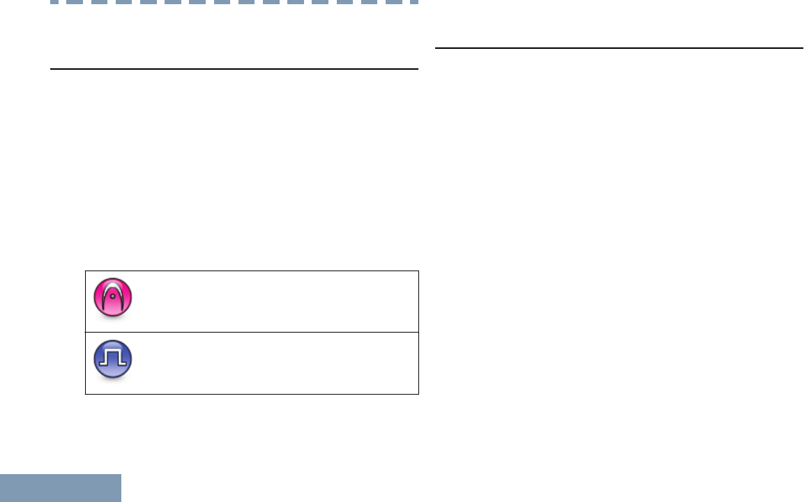
Throughout this publication, the icons described next
are used to indicate features supported in either the
conventional Analog mode or conventional Digital
mode:
Indicates a conventional Analog Mode-
Only feature.
Indicates a conventional Digital Mode-
Only feature.
For features that are available in both conventional
Analog and Digital modes, no icon is shown.
What Your Dealer/System Administrator Can
Tell You
You can consult your dealer or system administrator
about the following:
• Is your radio programmed with any preset
conventional channels?
• Which buttons have been programmed to access
other features?
• What optional accessories may suit your needs?
• What are the best radio usage practices for
effective communication?
• What maintenance procedures will help promote
longer radio life?
Getting Started
12
English
Preparing Your Radio for Use
Charging the Battery
Important:
ALWAYS charge your IMPRES battery with
an IMPRES charger for optimized battery life
and valuable battery data. IMPRES batteries
charged exclusively with IMPRES chargers
receive a 6-month capacity warranty extension
over the standard Motorola Premium battery
warranty duration.
Your radio is powered by a Lithium-Ion (Li-lon)
battery. To avoid damage and to ensure compliance
with warranty terms, charge the battery using a
Motorola charger exactly as described in the charger
user guide. It is recommended your radio remains
powered off while charging.
Charge a new battery 14 to 16 hours before initial use
for best performance.
Attaching the Battery
Note:
If user inadvertently attaches a UL battery to
an FM approved radio or vice versa, the
certification on the radio will be voided. Your
radio can be preprogrammed via CPS to alert
you if this battery mismatch occurs. Check
with your dealer or system administrator to
determine how your radio has been
programmed. This battery mismatch alert
feature is only applicable for IMPRES battery
and Non-IMPRES battery with kit number
programmed in Erasable Programmable Read
Only Memory (EPROM).
When the radio is attached with the wrong
battery, a low pitched warning tone sounds,
the LED lights up blinking red, display shows
Wrong Battery and the Voice
Announcement/Text-to-Speech sounds Wrong
Battery if the Voice Announcement/Text-to-
Speech is loaded via CPS.
1Align the battery with the rails on the back of the
radio. Press the battery firmly, and slide upwards
until the latch snaps into place.
Preparing Your Radio for Use
13
English
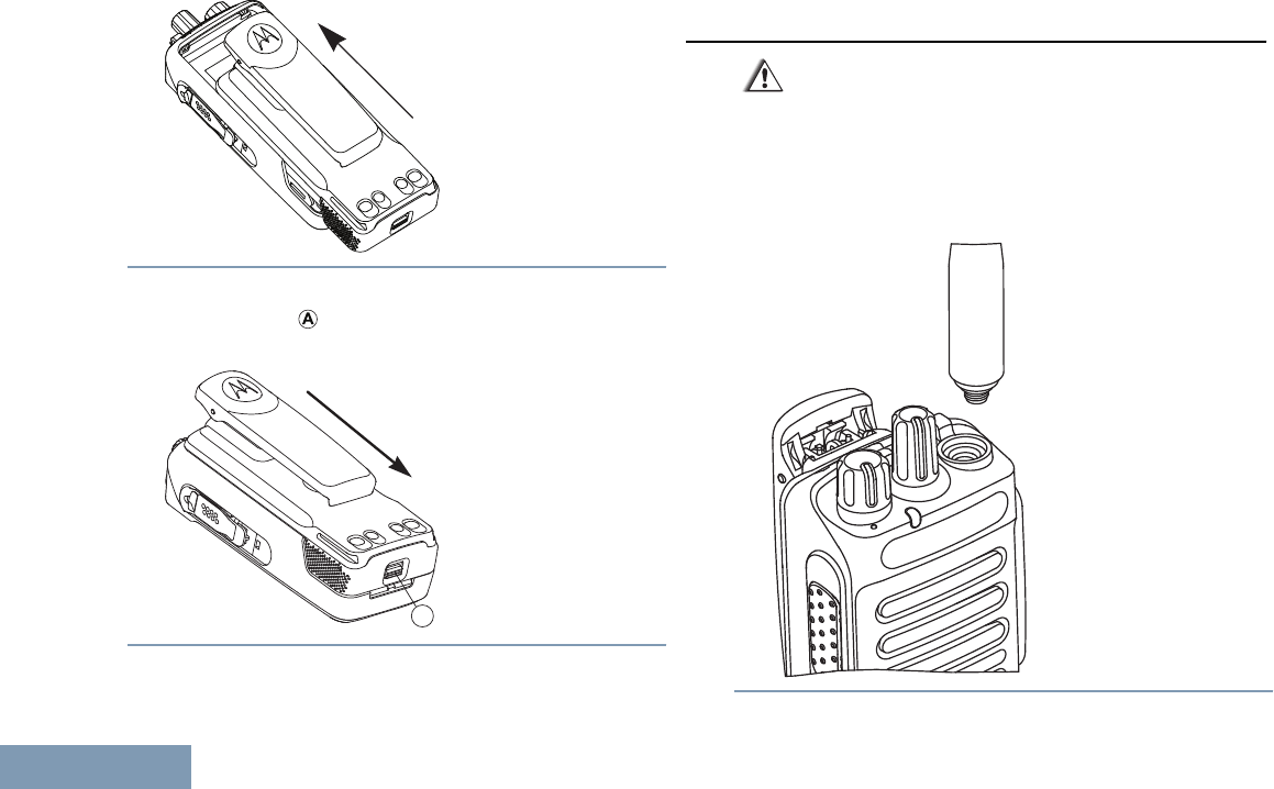
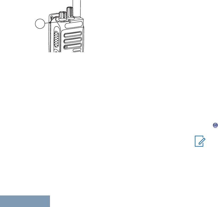
2To remove the battery, turn the radio off. Move the
battery latch ( ) into unlock position and hold, and
slide the battery down and off the rails.
A
Attaching the Antenna
Caution:
If antenna needs to be replaced, ensure that
only MOTOTRBO antennas are used.
Neglecting this will damage your radio.
1With the radio turned off, set the antenna in its
receptacle and turn clockwise.
Preparing Your Radio for Use
14
English
2To remove the antenna, turn the antenna
counterclockwise.
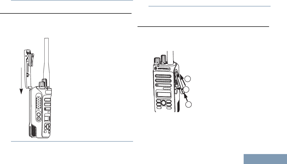
Attaching the Belt Clip
1To attach the belt clip, align the grooves on the
clip with those on the battery and press downward
until you hear a click.
2To remove the belt clip, press the belt clip tab
away from the battery using a key. Then slide the
clip upward and away from the radio.
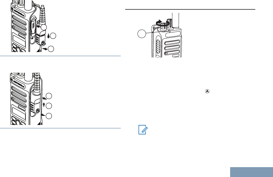
Attaching the Universal Connector Cover
(Dust Cover)
The universal connector is located on the antenna
side of the radio. It is used to connect MOTOTRBO
accessories to the radio.
1
2
3
Insert the slanted end of the cover into the slots
above the universal connector. Press downward on
the cover to seat the dust cover properly on the
Universal Connector.
Preparing Your Radio for Use
15
English

Secure the dust cover to the radio by pushing the
latch upwards.
To remove the dust cover, push the latch downwards.
Lift up the cover and slide down the dust cover from
the universal connector to remove it.
Replace the dust cover when the universal connector
is not in use.
If the radio is exposed to water, dry the universal
connector before attaching an accessory or replacing
the dust cover.
If the radio is exposed to salt water or contaminants,
perform the following cleaning procedure.
1Mix one tablespoon of mild dishwashing detergent
with one gallon of water to produce a 0.5 percent
solution.
2Clean only the external surfaces of the radio with
the solution. Apply the solution sparingly with a
stiff, nonmetallic, short-bristled brush.
3Dry the radio thoroughly with a soft and lint-free
cloth. Ensure the contact surface of the universal
connector is clean and dry.
4Apply Deoxit Gold Cleaner or Lubricant Pen
(Manufacturer CAIG Labs, Part number G100P)
on the contact surface of the universal connector.
5Attach an accessory to the universal connector to
test the connectivity.
Note:
Do not submerge the radio in water. Ensure
excess detergent does not get trapped in
between the universal connector, controls, or
crevices.
Clean the radio once a month for maintenance. For a
harsher environment such as in petrochemical plants
or in a high salt density marine environment, clean
the radio more often.
Attaching the Accessory Connector
The accessory connector is to be secured to the
universal connector on the antenna side of the radio.
1To attach the accessory connector, refer to the
steps shown in the diagram.
Preparing Your Radio for Use
16
English
1
2
3
2To remove the accessory connector, refer to the
steps shown in the diagram.
1
2
3
Powering Up the Radio
A
Rotate the On/Off/Volume Control Knob clockwise
until you hear a click. You see MOTOTRBO (TM) on the
display of the radio momentarily, followed by a
welcome message.
The LED lights up solid green ( ) and the Home
screen lights up if the backlight setting is set to turn
on automatically.
A brief tone sounds, indicating that the power up test
is successful.
Note:
There is no power up tone if the radio tones/
alerts function is disabled (see Turning the
Radio Tones/Alerts On or Off on page 83).
Preparing Your Radio for Use
17
English
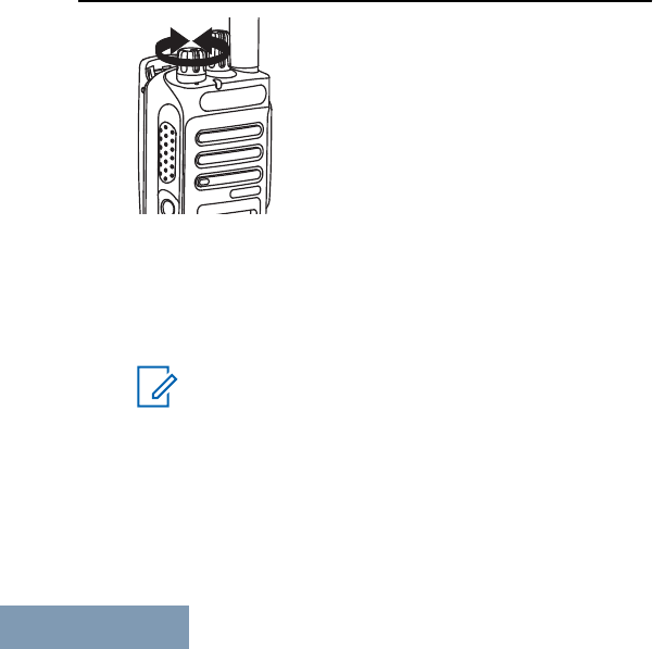
Turn off the radio by rotating this knob
counterclockwise until you hear a click. You see a
brief Powering Down on the display of the radio.
Adjusting the Volume
Increase the volume by turning the On/Off/Volume
Control Knob clockwise.
Decrease the volume by turning this knob
counterclockwise.
Note:
Your radio can be programmed to have a
minimum volume offset where the volume
level cannot be lowered past the programmed
minimum volume. Check with your dealer or
system administrator for more information.
Preparing Your Radio for Use
18
English
Identifying Radio Controls
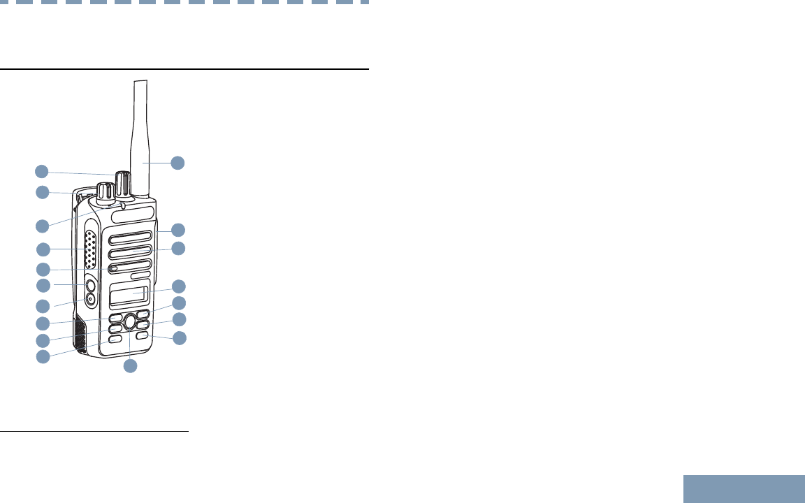
Radio Controls
11
3
14
13
12
8
7
6
5
2
1
9
4
10
15
16
17
18
1Channel Selector Knob
2On/Off/Volume Control Knob
3LED Indicator
4Push-to-Talk (PTT) Button
5Microphone
6Side Button 1[1]
7Side Button 2[1]
8Left Navigation Button
9Menu Button
10 Front Button P1[1]
11 OK Button
12 Front Button P2[1]
13 Back/Home Button
14 Right Navigation Button
15 Display
16 Speaker
17 Universal Connector for Accessories
18 Antenna
1These buttons are programmable.
Identifying Radio Controls
19
English

Programmable Buttons
Your dealer can program the programmable buttons
as shortcuts to radio functions depending on the
duration of a button press:
Short press Pressing and releasing rapidly.
Long press Pressing and holding for the
programmed duration.
Press and hold Keeping the button pressed.
Note:
The programmed duration of a button press is
applicable for all assignable radio/utility
functions or settings. See Emergency
Operation on page 63 for more information
on the programmed duration of the
Emergency button.
Assignable Radio Functions
Audio Profiles Allows the user to select the
preferred audio profile.
Audio Routing Toggles audio routing
between internal and external
speakers.
Audio Toggle Toggles audio routing
between the internal radio
speaker and the speaker of
wired accessory.
Contacts Provides direct access to the
Contacts list.
Call Alert Provides direct access to the
contacts list for you to select a
contact to whom a Call Alert
can be sent.
Call Forwarding Toggles Call Forwarding on or
off.
Call Log Selects the call log list.
Channel
Announcement
Plays zone and channel
announcement voice
messages for the current
channel.
Emergency Depending on the
programming, initiates or
cancels an emergency.
Intelligent Audio Toggles intelligent audio on or
off.
Identifying Radio Controls
20
English

Manual Site Roam Starts the manual site search.
Mic AGC On/Off Toggles the internal
microphone automatic gain
control (AGC) on or off.
Monitor Monitors a selected channel
for activity.
Notifications Provides direct access to the
Notifications list.
Nuisance Channel
Delete
Temporarily removes an
unwanted channel, except for
the Selected Channel, from
the scan list. The Selected
Channel refers to the selected
zone or channel combination
of the user from which scan is
initiated.
One Touch Access Directly initiates a predefined
Private, Phone or Group Call,
a Call Alert or a Quick Text
message.
Permanent Monitor Monitors a selected channel
for all radio traffic until
function is disabled.
Phone Provides direct access to the
Phone Contacts list.
Privacy Toggles privacy on or off.
Radio Alias and ID Provides radio alias and ID.
Radio Check Determines if a radio is active
in a system.
Radio Enable Allows a target radio to be
remotely enabled.
Radio Disable Allows a target radio to be
remotely disabled.
Repeater/
Talkaround
Toggles between using a
repeater and communicating
directly with another radio.
Scan Toggles scan on or off.
Site Lock On/Off When toggled on, the radio
searches the current site only.
When toggled off, the radio
Identifying Radio Controls
21
English
searches other sites in
addition to the current site.
Text Message Selects the text message
menu.
Transmit Interrupt
Remote Dekey
Stops an ongoing interruptible
call to free the channel.
Trill Enhancement
On/Off
Toggles trill enhancement on
or off.
Voice
Announcement
On/Off
Toggles voice announcement
on or off.
Voice Operating
Transmission
(VOX)
Toggles VOX on or off.
Zone Allows selection from a list of
zones.
Assignable Settings or Utility Functions
All Tones/Alerts Toggles all tones and alerts on
or off.
Backlight Toggles display backlight on or
off.
Backlight
Brightness
Adjusts the brightness level.
Power Level Toggles transmit power level
between high and low.
Squelch Toggles squelch level between
tight and normal.
Accessing the Programmed Functions
You can access various radio functions through one
of the following ways:
2Not applicable in Capacity Plus and Linked Capacity Plus
Identifying Radio Controls
22
English
• A short or long press of the relevant
programmable buttons.
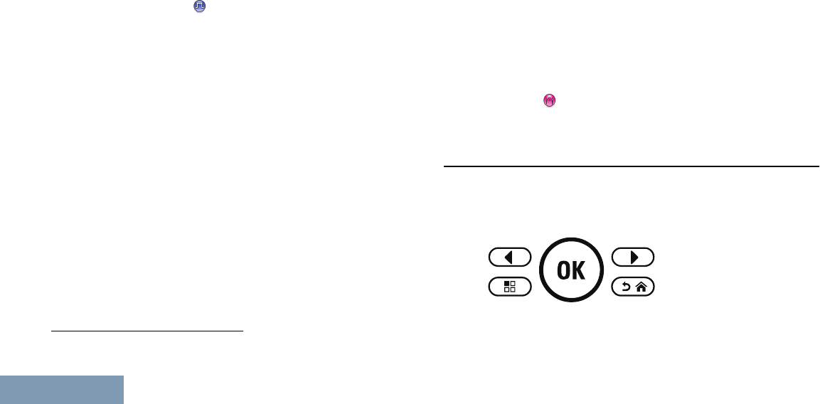
• Use the Menu Navigation Buttons as follows:
1Press to access the menu. Press the
appropriate Menu Scroll button ( or ) to
access the menu functions.
2To select a function or enter a sub-menu, press
the button.
3To go back one menu level, or to return to the
previous screen, press the button. Long
press the button to return to the Home
screen.
Note:
Your radio automatically exits the menu
after a period of inactivity and returns to
your Home screen.
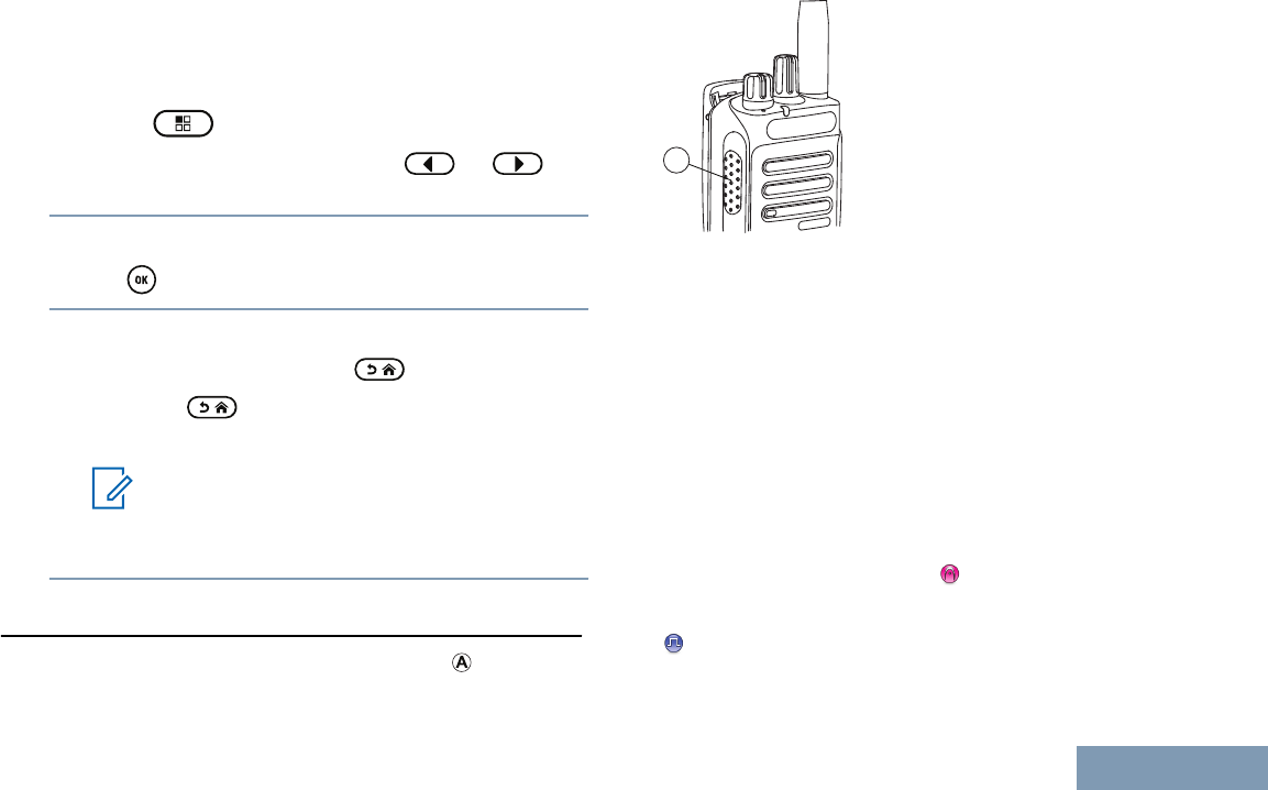
Push-To-Talk (PTT) Button
The PTT button on the side of the radio ( ) serves
two basic purposes:
A
• While a call is in progress, the PTT button allows
the radio to transmit to other radios in the call.
Press and hold the PTT button to talk. Release the
PTT button to listen.
The microphone is activated when the PTT button
is pressed.
• While a call is not in progress, the PTT button is
used to make a new call (see Making a Radio Call
on page 38).
If the Talk Permit Tone (see Turning the Talk Permit
Tone On or Off on page 85) is enabled, wait until
the short alert tone ends before talking.
During a call, if the Channel Free Indication feature
is enabled on your radio (programmed by your
Identifying Radio Controls
23
English
dealer), you will hear a short alert tone the moment
the target radio (the radio that is receiving your call)
releases the PTT button, indicating the channel is
free for you to respond.
You will also hear a continuous talk prohibit tone, if
your call is interrupted, indicating that you should
release the PTT button, for example when the radio
receives an Emergency Call.
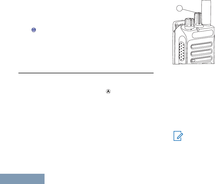
Switching Between Conventional Analog and
Digital Mode
Each channel in your radio can be configured as a
conventional analog or conventional digital channel.
Use the Channel Selector Knob ( ) to switch
between an analog or a digital channel.
A
When switching from digital to analog mode, certain
features are unavailable. Icons for the digital features
(such as Messages) reflect this change by appearing
‘grayed out’. Disabled features are hidden in the
menu.
Your radio also has features available in both analog
and digital mode. However, the minor differences in
the way each feature works does not affect the
performance of your radio.
Note:
Your radio also switches between digital and
analog modes during a dual mode scan (see
Scan on page 51).
Identifying Radio Controls
24
English

IP Site Connect
This feature allows your radio to extend conventional
communication beyond the reach of a single site, by
connecting to different available sites which are
connected via an Internet Protocol (IP) network.
When the radio moves out of range from one site and
into the range of another, it connects to the new site's
repeater to send or receive calls/data transmissions.
Depending on your settings, this is done
automatically or manually.
If the radio is set to do this automatically, it scans
through all available sites when the signal from the
current site is weak or when the radio is unable to
detect any signal from the current site. It then locks
on to the repeater with the strongest Received Signal
Strength Indicator (RSSI) value.
In a manual site search, the radio searches for the
next site in the roam list that is currently in range (but
which may not have the strongest signal) and locks
on to it.
Note:
Each channel can only have either Scan or
Roam enabled, not both at the same time.
Channels with this feature enabled can be added to a
particular roam list. The radio searches the channel(s)
in the roam list during the automatic roam operation
to locate the best site.
A roam list supports a maximum of 16 channels
(including the Selected Channel).
Note:
You cannot manually add or delete an entry to
the roam list. Check with your dealer or
system administrator for more information.
Capacity Plus
Capacity Plus is a single-site trunking configuration of
the MOTOTRBO radio system, which uses a pool of
channels to support hundreds of users and up to 254
Groups. This feature allows your radio to efficiently
utilize the available number of programmed channels
while in Repeater Mode.
You hear a negative indicator tone if you try to access
a feature not applicable to Capacity Plus via a
programmable button press.
Your radio also has features that are available in
conventional digital mode, IP Site Connect, Capacity
Plus and Linked Capacity Plus. However, the minor
Identifying Radio Controls
25
English

differences in the way each feature works does not
affect the performance of your radio.
Check with your dealer or system administrator for
more information on this configuration.
Linked Capacity Plus
Linked Capacity Plus is a multi-site multi-channel
trunking configuration of the MOTOTRBO radio
system, combining the best of both Capacity Plus and
IP Site Connect configurations.
Linked Capacity Plus allows your radio to extend
trunking communication beyond the reach of a single
site, by connecting to different available sites which
are connected via an Internet Protocol (IP) network. It
also provides an increase in capacity by efficiently
utilizing the combined available number of
programmed channels supported by each of the
available sites.
When the radio moves out of range from one site and
into the range of another, it connects to the new site's
repeater to send or receive calls/data transmissions.
Depending on your settings, this is done
automatically or manually.
If the radio is set to do this automatically, it scans
through all available sites when the signal from the
current site is weak or when the radio is unable to
detect any signal from the current site. It then locks
on to the repeater with the strongest Received Signal
Strength Indicator (RSSI) value.
In a manual site search, the radio searches for the
next site in the roam list that is currently in range (but
which may not have the strongest signal) and locks
on to it.
Any channel with Linked Capacity Plus enabled can
be added to a particular roam list. The radio searches
these channels during the automatic roam operation
to locate the best site.
Note:
You cannot manually add or delete an entry to
the roam list. Check with your dealer or
system administrator for more information.
Similar to Capacity Plus, icons of features not
applicable to Linked Capacity Plus are not available
in the menu. You hear a negative indicator tone if you
try to access a feature not applicable to Linked
Capacity Plus via a programmable button press.
Identifying Radio Controls
26
English

Check with your dealer or system administrator for
more information on this configuration.
Identifying Radio Controls
27
English
Identifying Status Indicators
Display Icons
The following are icons that appear on the display of
the radio.
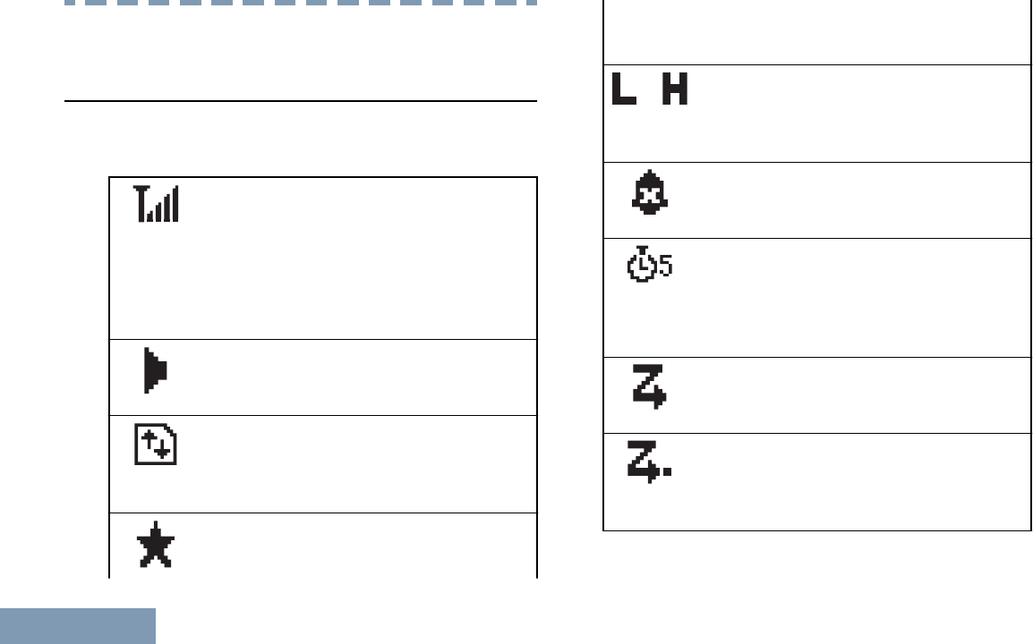
Received Signal Strength Indicator
(RSSI)
The number of bars displayed repre-
sents the radio signal strength. Four
bars indicate the strongest signal. This
icon is only displayed while receiving.
Monitor
Selected channel is being monitored.
High Volume Data
Radio is receiving high volume data and
channel is busy.
Notification
Notification List has one or more missed
events.
or Power Level
Radio is set at Low power or Radio is
set at High power.
Tones Disable
Tones are turned off.
Over-the-Air Programming Delay Tim-
er
Indicates time left before automatic re-
start of radio.
Scan[3][4]
Scan feature is enabled.
Scan- Priority 1[3][4]
Radio detects activity on channel/group
designated as Priority 1.
Identifying Status Indicators
28
English
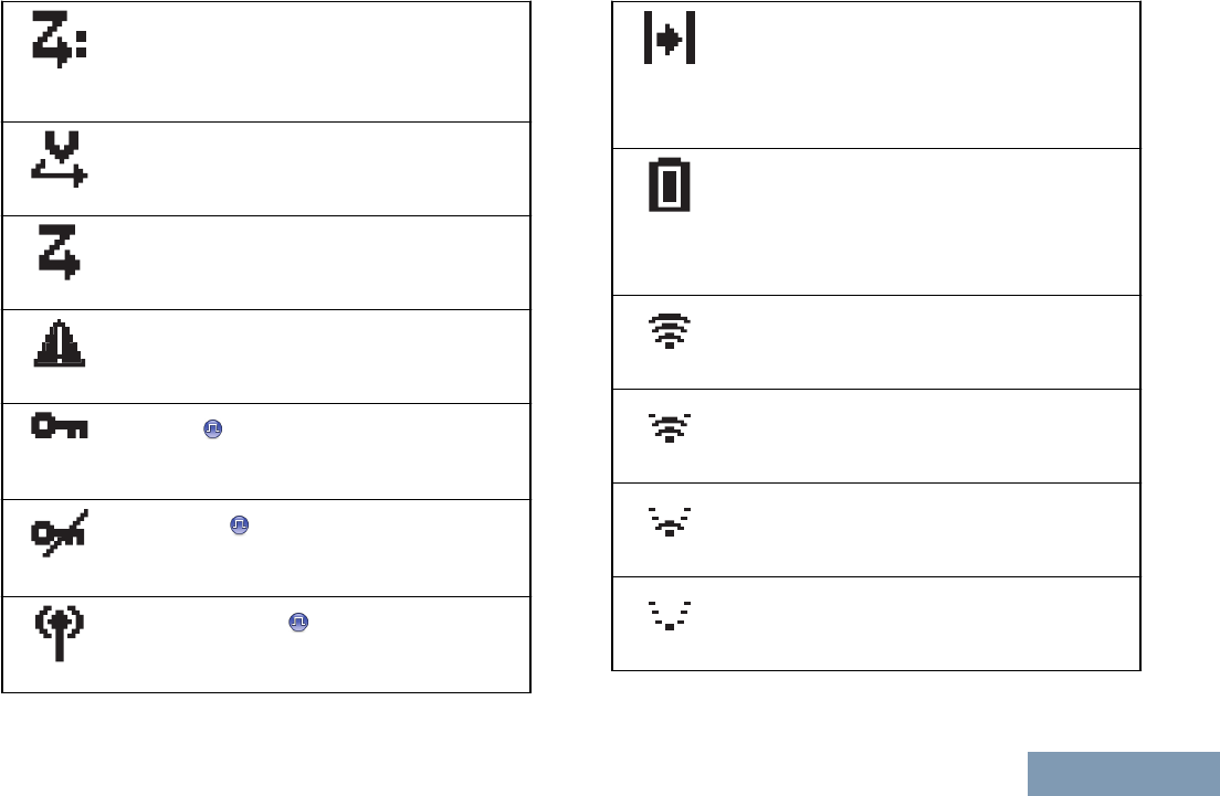
Scan- Priority 2[3][4]
Radio detects activity on channel/group
designated as Priority 2.
Vote Scan
Vote scan feature is enabled.
Flexible Receive List
Flexible receive list is enabled.
Emergency
Radio is in Emergency mode.
Secure
The Privacy feature is enabled.
Unsecure
The Privacy feature is disabled.
Site Roaming[3]
The site roaming feature is enabled.
Talkaround[3][4]
In the absence of a repeater, radio is
currently configured for direct radio to ra-
dio communication.
Battery
The number of bars (0 – 4) shown indi-
cates the charge remaining in the bat-
tery. Blinks when the battery is low.
Wi-Fi Excellent[5]
Wi-Fi signal is excellent.
Wi-Fi Good[5]
Wi-Fi signal is good.
Wi-Fi Average[5]
Wi-Fi signal is average.
Wi-Fi Poor[5]
Wi-Fi signal is poor.
Identifying Status Indicators
29
English
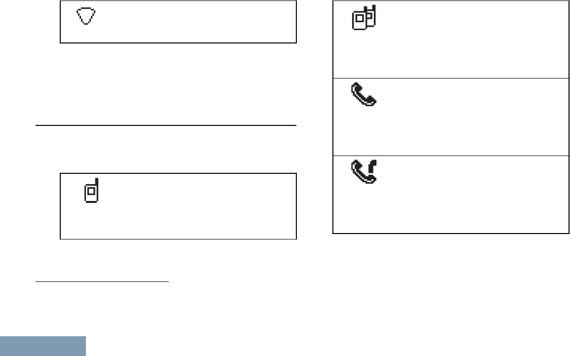
Wi-Fi Unavailable[5]
Wi-Fi signal is unavailable.
Call Icons
The following icons appear on the radio’s display
during a call. These icons also appear in the Contacts
list to indicate ID type.
Private Call
Indicates a Private Call in progress. In
the Contacts list, it indicates a sub-
scriber alias (name) or ID (number).
Group Call/All Call
Indicates a Group Call or All Call in
progress. In the Contacts list, it indi-
cates a group alias (name) or ID
(number).
Phone Call as Private Call
Indicates a Phone Call as Private Call
in progress. In the Contacts list, it indi-
cates a phone alias (name) or ID
(number).
Phone Call as Group Call
Indicates a Phone Call as Group/All
Call in progress. In the Contacts list, it
indicates a phone alias (name) or ID
(number).
3Not applicable in Capacity Plus
4Not applicable in Linked Capacity Plus
5Only applicable for XPR 3500e
Identifying Status Indicators
30
English
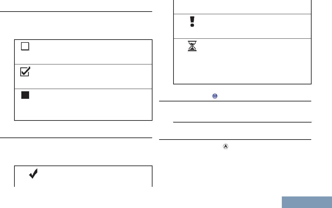
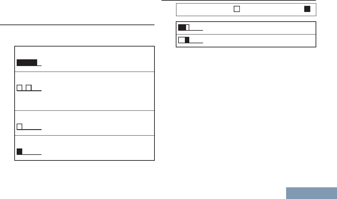
Advanced Menu Icons
The following icons appear beside menu items that
offer a choice between two options or as an indication
that there is a sub-menu offering two options.
Checkbox (Empty)
Indicates the option is not selected.
Checkbox (Checked)
Indicates the option is selected.
Solid Black Box
Indicates the option selected for the menu
item with a sub-menu.
Mini Notice Icons
The following icons appear momentarily on the
radio’s display after an action to perform task is
taken.
Successful Transmission (Posi-
tive)
Successful action taken.
Failed Transmission (Negative)
Failed action taken.
Transmission in Progress (Transi-
tional)
Transmitting. This is seen before indi-
cation for Successful Transmission or
Failed Transmission.
Sent Item Icons
The following icons appear at the top right corner of
the radio’s display in the Sent Items folder.
LED Indicator
The LED indicator ( ) shows the operational status of
your radio.
Identifying Status Indicators
31
English
A
Blinking
red
Battery mismatch occurs or radio is
transmitting at low battery condition,
receiving an emergency transmission
or has failed the self-test upon
powering up, or has moved out of
range if radio is configured with Auto-
Range Transponder System.
Solid
yellow
Radio is monitoring a conventional
channel. Also indicates fair battery
charge when programmable button is
pressed.
Blinking
yellow
Radio is scanning for activity or
receiving a Call Alert, flexible receive
list is enabled or all local Linked
Capacity Plus channels are busy.
Double
blinking
yellow
Radio is no longer connected to the
repeater while in Capacity Plus or
Linked Capacity Plus; all Capacity Plus
or Linked Capacity Plus channels are
currently busy.
Solid
green
Radio is powering up or transmitting.
Also indicates full charge of the battery
when the programmable button is
pressed.
Blinking
green
Radio is powering up, receiving a non-
privacy-enabled call or data, or
detecting activity, or retrieving Over-
the-Air Programming transmissions
over the air.
Rapidly
blinking
green
Radio is receiving a privacy-enabled
call or data.
Note:
While in conventional mode, when the LED
blinks green, it indicates the radio detects
activity over the air. Due to the nature of the
digital protocol, this activity may or may not
affect the radio's programmed channel.
Identifying Status Indicators
32
English
For Capacity Plus and Linked Capacity Plus,
there is no LED indication when the radio is
detecting activity over the air.
Alert Tones
Alert tones provide you with audible indications of the
status, or response to data received on the radio.
Continuous Tone A monotone sound.
Sounds continuously un-
til termination.
Periodic Tone Sounds periodically de-
pending on the duration
set by the radio. Tone
starts, stops, and repeats
itself.
Repetitive Tone A single tone that re-
peats itself until it is ter-
minated by the user.
Momentary Tone Sounds only once for a
short period of time de-
fined by the radio.
Indicator Tones
High pitched tone Low pitched tone
Positive Indicator Tone
Negative Indicator Tone
Identifying Status Indicators
33
English
Making and Receiving Calls
Selecting a Zone
A zone is a group of channels. Your radio supports up
to 128 channels and 50 zones, with a maximum of 16
channels per zone.
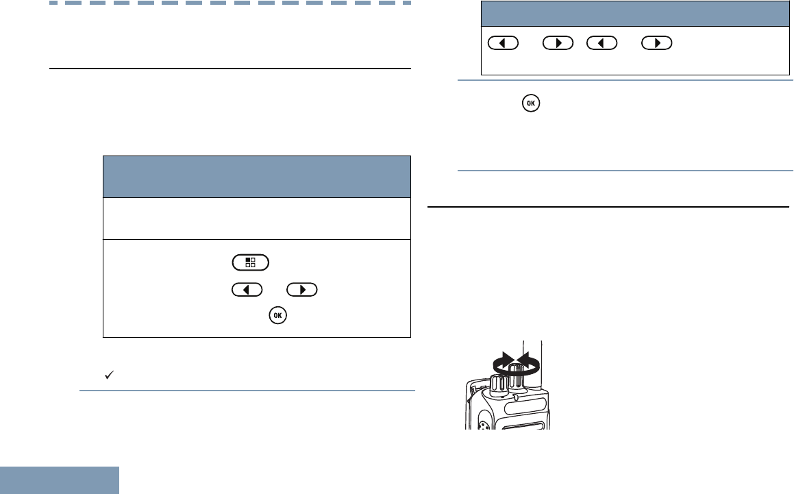
1Access the Zone feature.
Radio Con-
trols
Steps
Programmed
Zone button
Press the programmed Zone
button.
Radio menu 1 to access the menu.
2 or to Zone and
press to select.
The current zone is displayed and indicated by a
.
2Select the required zone.
Radio Control Steps
or or and scroll to the
required zone.
3Press to select.
The display shows <Zone> Selected
momentarily and returns to the selected zone
screen.
Selecting a Channel
Transmissions are sent and received on a channel.
Depending on your radio’s configuration, each
channel may have been programmed differently to
support different groups of users or supplied with
different features. After selecting the relevant Zone,
select the relevant channel you require to transmit or
receive on.
Making and Receiving Calls
34
English

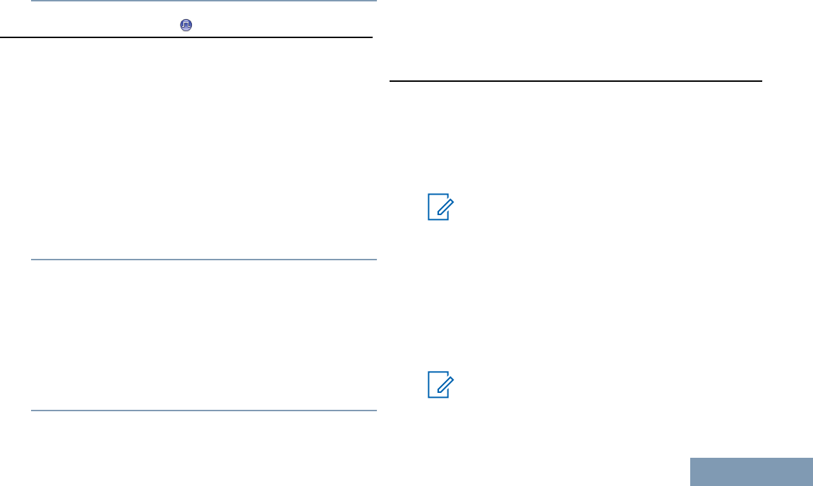
Once the required zone is displayed (if you have
multiple zones in your radio), turn the programmed
Channel Selector Knob to select the channel.
Receiving and Responding to a Radio Call
Once the channel, subscriber ID, or group ID is
displayed, you can proceed to receive and respond to
calls.
The LED lights up solid green while the radio is
transmitting and blinks green when the radio is
receiving.
Note:
The LED lights up solid green while the radio
is transmitting and blinks greenrapidly when
the radio is receiving a privacy-enabled call
and blinks green when receiving a non-
privacy-enabled call.
To unscramble a privacy-enabled call, your
radio must have the same Privacy Key, OR
the same Key Value and Key ID (programmed
by your dealer), as the transmitting radio (the
radio you are receiving the call from).
See Privacy on page 68 for more
information.
Receiving and Responding to a Group Call
To receive a call from a group of users, your radio
must be configured as part of that group.
When you receive a Group Call (while on the Home
screen), the LED blinks green. The Group Call icon
appears in the top right corner. The first text line
shows the caller alias. The second text line displays
the group call alias. Your radio unmutes and the
incoming call sounds through the radio's speaker.
1Hold the radio vertically 1 to 2 inches (2.5 to 5.0
cm) from your mouth.
• If the Channel Free Indication feature is
enabled, you hear a short alert tone the
moment the transmitting radio releases the
PTT button, indicating the channel is free for
you to respond. Press the PTT button to
respond.
• If the Voice Interrupt feature is enabled,
press the PTT button to stop the current call
from the transmitting radio and free the channel
for you to talk/respond.
Making and Receiving Calls
35
English

The LED lights up solid green.
2Wait for one of the following tones to finish (if
enabled), and speak clearly into the microphone.
• The Talk Permit Tone
•The PTT Sidetone
3Release the PTT button to listen.
If there is no voice activity for a predetermined period
of time, the call ends.
Note:
See Making a Group Call on page 38 for
details on making a Group Call.
If the radio receives a Group Call while not on
the Home screen, it remains on its current
screen prior to answering the call.
Long press the button to go to the
Home screen to view the caller alias before
replying.
Receiving and Responding to a Private Call
A Private Call is a call from an individual radio to
another individual radio.
Depending on how your radio is programmed,
• The LED lights up solid yellow momentarily. Then,
the LED blinks green.
• The LED blinks green.
The first text line shows private call icon. The second
text line displays the private call alias. Your radio
unmutes and the incoming call sounds through the
speaker of the radio.
1Hold the radio vertically 1 to 2 inches (2.5 to 5.0
cm) from your mouth.
• If the Channel Free Indication feature is
enabled, you hear a short alert tone the
moment the transmitting radio releases the
PTT button, indicating the channel is free for
you to respond. Press the PTT button to
respond.
• If the Voice Interrupt feature is enabled,
press the PTT button to stop the current call
from the transmitting radio and free the channel
for you to talk/respond.
The LED lights up solid green.
Making and Receiving Calls
36
English

2Wait for the Talk Permit Tone to finish (if enabled),
and speak clearly into the microphone.
3Release the PTT button to listen.
If there is no voice activity for a predetermined period
of time, the call ends.
The display shows Call Ended.
See Making a Private Call on page 39 for details on
making a Private Call.
Receiving an All Call
An All Call is a call from an individual radio to every
radio on the channel. It is used to make important
announcements requiring the user’s full attention.
When you receive an All Call, a tone sounds and the
LED blinks green.
The Group Call icon appears in the top right corner.
The first text line shows the caller alias. The second
text line displays All Call. Your radio unmutes and
the incoming call sounds through the radio speaker.
Once the All Call ends, the radio returns to the
previous screen before receiving the call. An All Call
does not wait for a predetermined time before ending.
If the Channel Free Indication feature is enabled,
you hear a short alert tone the moment the
transmitting radio releases the PTT button, indicating
the channel is now available for use.
You cannot respond to an All Call.
Note:
See Making an All Call on page 40 for
details on making an All Call.
Note:
The radio stops receiving the All Call if you
switch to a different channel while receiving
the call. During an All Call, you will not be able
to use any programmed button functions until
the call ends.
Receiving and Responding to a Selective Call
A Selective Call is a call from an individual radio to
another individual radio. It is a Private Call on an
analog system.
When you receive a Selective Call, the LED blinks
green. The Private Call icon appears in the top right
corner. The first text line shows the caller alias or
Selective Call or Alert with Call. The first text
line shows the Private Call icon. The radio displays
Making and Receiving Calls
37
English

Selective Call or Alert with Call. Your radio
unmutes and the incoming call sounds through the
radio's speaker.
1Hold the radio vertically 1 to 2 inches (2.5 to 5.0
cm) from your mouth.
2Press the PTT button to respond to the call.
The LED lights up solid green.
3Wait for the Talk Permit Tone to finish (if enabled),
and speak clearly into the microphone.
4Release the PTT button to listen.
If there is no voice activity for a predetermined period
of time, the call ends.
The display shows Call Ended.
See Making a Private Call on page 39 for details on
making a Private Call.
Making a Radio Call
After selecting your channel, you can select a
subscriber alias or ID, or group alias or ID by using:
• The Channel Selector Knob.
• A programmed One Touch Access button (see
Making a Phone Call with the One Touch Access
Button).
• A programmable button – This method is for
Phone Calls only (see Making a Phone Call with
the Programmable Phone Button).
• The Contacts list (see Contact Settings on page
53).
Note:
Your radio must have the Privacy feature
enabled on the channel to send a privacy-
enabled transmission. Only target radios with
the same Privacy Key OR the same Key Value
and Key ID as your radio will be able to
unscramble the transmission.
Note:
See Privacy on page 68 for more
information.
Making a Group Call
To make a call to a group of users, your radio must
be configured as part of that group.
1Do one of the following.
Making and Receiving Calls
38
English

• Select the channel with the active group alias
or ID. See Selecting a Channel on page 34.
• Press the programmed One Touch Access
button.
2Hold the radio vertically 1 to 2 inches (2.5 to 5.0
cm) from your mouth.
3Press the PTT button to make the call.
The LED lights up solid green. The first text line
shows the group call icon. The second text line
shows the group call alias.
4Release the PTT button to listen.
When the target radio responds, the LED blinks
green. You see the Group Call icon, the group
alias or ID, and transmitting radio alias or ID on
your display.
5 If the Channel Free Indication feature is
enabled, you hear a short alert tone the moment
the transmitting radio releases the PTT button,
indicating the channel is free for you to respond.
Press the PTT button to respond.
If there is no voice activity for a predetermined
period of time, the call ends. Radio returns to the
screen you were on prior to initiating the call.
Making a Private Call
While you can receive and/or respond to a Private
Call initiated by an authorized individual radio, your
radio must be programmed for you to initiate a Private
Call.
There are two types of Private Calls. The first type,
where a radio presence check is performed prior to
setting up the call, while the other sets up the call
immediately.
Only one of these call types can be programmed to
your radio by your dealer.
You will hear a negative indicator tone, when you
make a Private Call via the One Touch Access
button, the programmed number keys, or the Channel
Selector Knob, if this feature is not enabled.
1Do one of the following.
• Select the channel with the active subscriber
alias or ID. See Selecting a Channel on page
34.
Making and Receiving Calls
39
English

• Press the programmed One Touch Access
button.
2Hold the radio vertically 1 to 2 inches (2.5 to 5.0
cm) from your mouth.
3Press the PTT button to make the call.
The LED lights up solid green. The first text line
shows the private call icon. The second text line
displays the private call alias.
4Wait for the Talk Permit Tone to finish (if enabled),
and speak clearly into the microphone.
5Release the PTT button to listen.
When the target radio responds, the LED blinks
green.
6 If the Channel Free Indication feature is
enabled, you hear a short alert tone the moment
the transmitting radio releases the PTT button,
indicating the channel is free for you to respond.
Press the PTT button to respond.
If there is no voice activity for a predetermined
period of time, the call ends. You hear a short
tone. The display shows Call Ended.
You can also make a Private Call via Contacts (see
Making a Private Call from Contacts on page 55).
Making an All Call
This feature allows you to transmit to all users on the
channel. Your radio must be programmed to allow
you to use this feature.
Users on the channel cannot respond to an All Call.
1Select the channel with the active All Call group
alias or ID. See Selecting a Channel on page 34.
2Hold the radio vertically 1 to 2 inches (2.5 to 5.0
cm) from your mouth.
3Press the PTT button to make the call.
The LED lights up solid green. The first text line
shows the All Call icon. The second text line
displays the All Call alias.
4Wait for one of the following tones to finish (if
enabled), and speak clearly into the microphone.
• The Talk Permit Tone
•The PTT Sidetone
Making and Receiving Calls
40
English

Making a Selective Call
Just like a Private Call, while you can receive and/or
respond to a Selective Call initiated by an authorized
individual radio, your radio must be programmed for
you to initiate a Selective Call.
1Select the channel with the active subscriber alias
or ID. See Selecting a Channel on page 34.
2Hold the radio vertically 1 to 2 inches (2.5 to 5.0
cm) from your mouth.
3Press the PTT button to make the call.
The LED lights up solid green. The Private Call
icon appears in the top right corner. The first text
line shows the subscriber alias. The second text
line displays the call status.
4Wait for one of the following tones to finish (if
enabled), and speak clearly into the microphone.
• The Talk Permit Tone
•The PTT Sidetone
5Release the PTT button to listen.
When the target radio responds, the LED blinks
green.
If the Channel Free Indication feature is
enabled, you hear a short alert tone the moment
the transmitting radio releases the PTT button,
indicating the channel is free for you to respond.
Press the PTT button to respond.
If there is no voice activity for a predetermined
period of time, the call ends.
The display shows Call Ended.
Making a Radio Call
After selecting your channel, you can select a
subscriber alias or ID, or group alias or ID by using:
• The Channel Selector Knob.
• A programmed One Touch Access button (see
Making a Phone Call with the One Touch Access
Button).
• A programmable button – This method is for
Phone Calls only (see Making a Phone Call with
the Programmable Phone Button).
• The Contacts list (see Contact Settings on page
53).
Making and Receiving Calls
41
English

Note:
Your radio must have the Privacy feature
enabled on the channel to send a privacy-
enabled transmission. Only target radios with
the same Privacy Key OR the same Key Value
and Key ID as your radio will be able to
unscramble the transmission.
Note:
See Privacy on page 68 for more
information.
Making a Group Call
To make a call to a group of users, your radio must
be configured as part of that group.
1Do one of the following.
• Select the channel with the active group alias
or ID. See Selecting a Channel on page 34.
• Press the programmed One Touch Access
button.
2Hold the radio vertically 1 to 2 inches (2.5 to 5.0
cm) from your mouth.
3Press the PTT button to make the call.
The LED lights up solid green. The first text line
shows the group call icon. The second text line
shows the group call alias.
4Release the PTT button to listen.
When the target radio responds, the LED blinks
green. You see the Group Call icon, the group
alias or ID, and transmitting radio alias or ID on
your display.
5 If the Channel Free Indication feature is
enabled, you hear a short alert tone the moment
the transmitting radio releases the PTT button,
indicating the channel is free for you to respond.
Press the PTT button to respond.
If there is no voice activity for a predetermined
period of time, the call ends. Radio returns to the
screen you were on prior to initiating the call.
Making a Private Call
While you can receive and/or respond to a Private
Call initiated by an authorized individual radio, your
radio must be programmed for you to initiate a Private
Call.
Making and Receiving Calls
42
English

There are two types of Private Calls. The first type,
where a radio presence check is performed prior to
setting up the call, while the other sets up the call
immediately.
Only one of these call types can be programmed to
your radio by your dealer.
You will hear a negative indicator tone, when you
make a Private Call via the One Touch Access
button, the programmed number keys, or the Channel
Selector Knob, if this feature is not enabled.
1Do one of the following.
• Select the channel with the active subscriber
alias or ID. See Selecting a Channel on page
34.
• Press the programmed One Touch Access
button.
2Hold the radio vertically 1 to 2 inches (2.5 to 5.0
cm) from your mouth.
3Press the PTT button to make the call.
The LED lights up solid green. The first text line
shows the private call icon. The second text line
displays the private call alias.
4Wait for the Talk Permit Tone to finish (if enabled),
and speak clearly into the microphone.
5Release the PTT button to listen.
When the target radio responds, the LED blinks
green.
6 If the Channel Free Indication feature is
enabled, you hear a short alert tone the moment
the transmitting radio releases the PTT button,
indicating the channel is free for you to respond.
Press the PTT button to respond.
If there is no voice activity for a predetermined
period of time, the call ends. You hear a short
tone. The display shows Call Ended.
You can also make a Private Call via Contacts (see
Making a Private Call from Contacts on page 55).
Making an All Call
This feature allows you to transmit to all users on the
channel. Your radio must be programmed to allow
you to use this feature.
Users on the channel cannot respond to an All Call.
Making and Receiving Calls
43
English

1Select the channel with the active All Call group
alias or ID. See Selecting a Channel on page 34.
2Hold the radio vertically 1 to 2 inches (2.5 to 5.0
cm) from your mouth.
3Press the PTT button to make the call.
The LED lights up solid green. The first text line
shows the All Call icon. The second text line
displays the All Call alias.
4Wait for one of the following tones to finish (if
enabled), and speak clearly into the microphone.
• The Talk Permit Tone
•The PTT Sidetone
Making a Selective Call
Just like a Private Call, while you can receive and/or
respond to a Selective Call initiated by an authorized
individual radio, your radio must be programmed for
you to initiate a Selective Call.
1Select the channel with the active subscriber alias
or ID. See Selecting a Channel on page 34.
2Hold the radio vertically 1 to 2 inches (2.5 to 5.0
cm) from your mouth.
3Press the PTT button to make the call.
The LED lights up solid green. The Private Call
icon appears in the top right corner. The first text
line shows the subscriber alias. The second text
line displays the call status.
4Wait for one of the following tones to finish (if
enabled), and speak clearly into the microphone.
• The Talk Permit Tone
•The PTT Sidetone
5Release the PTT button to listen.
When the target radio responds, the LED blinks
green.
If the Channel Free Indication feature is
enabled, you hear a short alert tone the moment
the transmitting radio releases the PTT button,
indicating the channel is free for you to respond.
Press the PTT button to respond.
If there is no voice activity for a predetermined
period of time, the call ends.
Making and Receiving Calls
44
English
The display shows Call Ended.
Stopping a Radio Call
This feature allows you to stop an ongoing Group or
Private Call to free the channel for transmission. For
example, when a radio experiences a “stuck
microphone” condition where the PTT button is
inadvertently pressed by the user.
Your radio must be programmed to allow you to use
this feature.
1Press the programmed Transmit Interrupt
Remote Dekey button, while on the relevant
channel.
The display shows Remote Dekey.
2Wait for acknowledgement.
If successful, the radio sounds a positive indicator
tone and the display shows Remote Dekey
Success, indicating that the channel is now free.
If unsuccessful, the radio sounds a negative
indicator tone and the display shows Remote
Dekey Failed.
On the interrupted radio, the remote radio’s display
shows Call Interrupted, and the radio sounds a
negative indicator tone until the PTT button is
released.
Talkaround
You can continue to communicate when your
repeater is not operating, or when your radio is out of
the repeater’s range but within talking range of other
radios.
This is called “talkaround”.
Note:
This feature is not applicable in Capacity Plus
and Linked Capacity Plus.
The Talkaround setting is retained even after
powering down.
You can toggle between talkaround and repeater
modes by pressing the programmed Repeater/
Talkaround button or using the radio menu as
described next.
Note:
This feature is not applicable in Citizens Band
channels that are in the same frequency.
Making and Receiving Calls
45
English
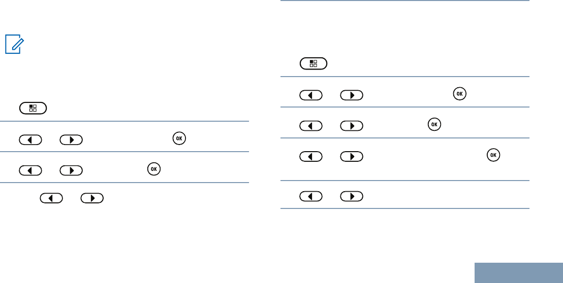
1 to access the menu.
2 or to Utilities and press to
select.
3 or to Radio Settings and press
to select.
4 or to Talkaround and press to
select.
You can also use or to change the selected
option.
5Press to enable/disable the Talkaround.
The display shows beside Enabled.
The disappears from beside Enabled.
Monitoring Features
Monitoring a Channel
Use the Monitor feature to make sure a channel is
clear before transmitting.
This feature is not applicable in Capacity Plus and
Linked Capacity Plus.
1Press and hold the programmed Monitor button
and listen for activity.
The Monitor icon appears on the display and the
LED lights up solid yellow. You hear radio activity
or total silence, depending on how your radio is
programmed. This indicates that the channel is in
use.
2 Wait until you hear “white noise”. This indicates
that the channel is free.
3Press the PTT button to talk and release it to
listen.
Permanent Monitor
Use the Permanent Monitor feature to continuously
monitor a selected channel for activity.
Making and Receiving Calls
46
English

Note:
This feature is not applicable in Capacity Plus
and Linked Capacity Plus.
1Press the programmed Permanent Monitor
button to activate permanent monitoring of the
channel.
Radio sounds an alert tone, the LED lights up solid
yellow, and the display shows Permanent
Monitor On. The Monitor icon appears on the
display.
2Press the programmed Permanent Monitor
button to exit Permanent Monitor mode.
Radio sounds an alert tone, the LED turns off, and
the display shows Permanent Monitor Off.
Making and Receiving Calls
47
English
Advanced Features
Radio Check
If enabled, this feature allows you to determine if
another radio is active in a system without disturbing
the user of that radio. No audible or visual notification
is shown on the target radio.
This feature is only applicable for subscriber aliases
or IDs.
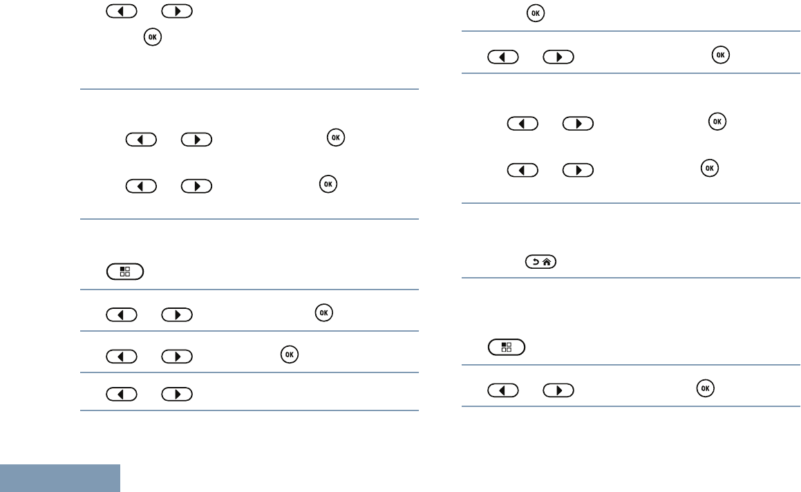
Sending a Radio Check
1Access the Radio Check feature.
Radio
Control
Steps
Program-
med Radio
Check but-
ton
1Press the programmed Radio
Check button.
2 or to the required
subscriber alias or ID and press
to select.
Radio
Control
Steps
Menu 1 to access the menu.
2 or to Contacts and
press to select.
3 or to Radio Check
and press to select.
The display shows The LED lights up solid green.
2Wait for acknowledgement.
If the button is pressed when the radio is
waiting for acknowledgement, a tone sounds, and
the radio terminates all retries and exits Radio
Check mode.
Radio returns to the subscriber alias or ID screen.
Scan Lists
Scan lists are created and assigned to individual
channels/groups. Your radio scans for voice activity
Advanced Features
48
English
by cycling through the channel/group sequence
specified in the scan list for the current channel/
group.
Your radio can support up to 250 scan lists, with a
maximum of 16 members in a list. Each scan list
supports a mixture of both analog and digital entries.
You can add, delete, or prioritize channels by editing
a scan list.
Note:
This feature is not applicable in Capacity Plus
and Linked Capacity Plus.
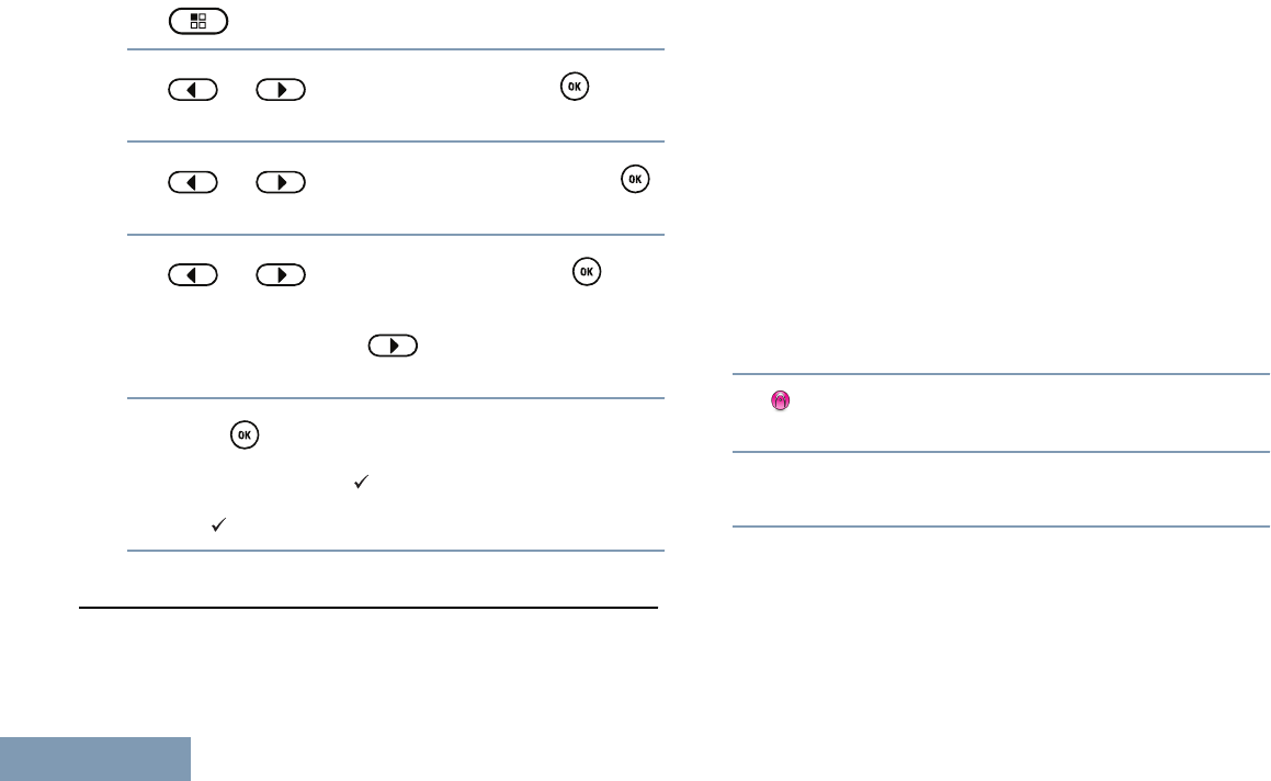
Viewing an Entry in the Scan List
1 to access the menu.
2 or to Scan and press to select.
3 or to and press to select.
4Use or to view each member on the
list.
The Priority icon appears left of the member’s
alias, if set, to indicate whether the member is on
a Priority 1 or Priority 2 channel list. You cannot
have multiple Priority 1 or Priority 2 channels in a
scan list.
There is no Priority icon if priority is set to None.
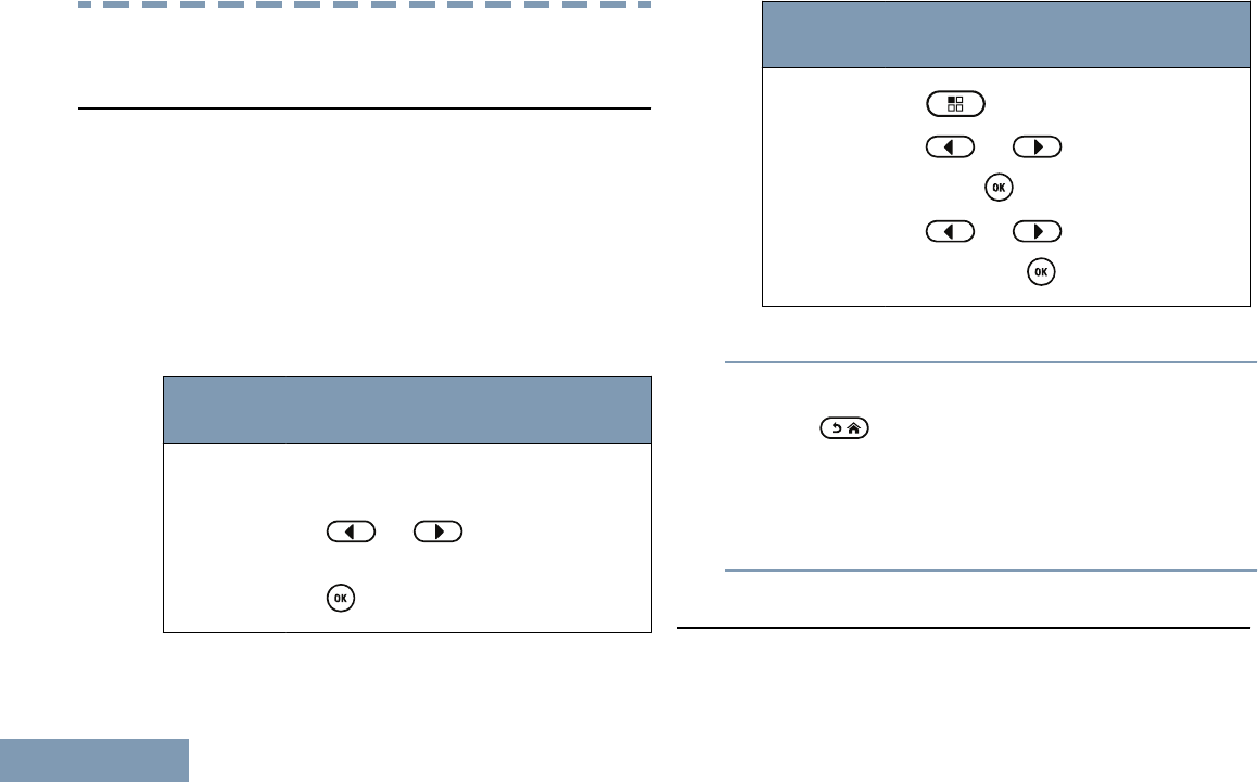
Editing the Scan List
Adding a New Entry to the Scan List
1 to access the menu.
2 or to Scan and press to select.
3 or to and press to select.
4 or to Add Member and press to
select.
5 or to the required alias or ID.
Advanced Features
49
English
6 or to the required priority level and
press to select.
The display shows , followed immediately by Add
Another?.
7Do one of the following:
• or to Yes and press to select,
and repeat Steps 5 to 6.
• or to No and press to save the
current list.
Deleting an Entry from the Scan List
1 to access the menu.
2 or to Scan and press to select.
3 or to and press to select.
4 or to the required alias or ID.
5Press to select.
6 or to Delete and press to select.
7Do one of the following:
• or to Yes and press to delete
entry. The display shows positive mini notice.
• or to No and press to return to
the previous screen.
8Repeat Steps 4 to 6 to delete other entries.
After deleting all required aliases or IDs, long
press to return to the Home screen.
Setting and Editing Priority for an Entry in the
Scan List
1 to access the menu.
2 or to Scan and press to select.
Advanced Features
50
English
3 or to and press to select.
4Press to select.
5 or to Edit Priority and press
to select.
6 or to the required priority level and
press to select.
The display shows before returning to the previous
screen.
Note:
The Priority icon appears left of the name
of the member.
There is no Priority icon if priority is set to
None.
Scan
When you start a scan, your radio cycles through the
programmed scan list for the current channel looking
for voice activity.
The LED blinks yellow.
There are two ways of initiating scan:
•Main Channel Scan (Manual): Your radio scans
all the channels/groups in your scan list. On
entering scan, your radio may (depending on the
settings) automatically start on the last scanned
“active” channel/group or on the channel where
scan was initiated.
•Auto Scan (Automatic): Your radio automatically
starts scanning when you select a channel/group
that has Auto Scan enabled.
Note:
This feature is not applicable in Capacity Plus
and Linked Capacity Plus.
Starting and Stopping Scan
1Use the Channel Selector Knob to select a
channel programmed with a scan list.
2 to access the menu.
3 or to Scan and press to select.
Advanced Features
51
English
4 or to Scan State and press to
select.
5 or to required scan state and press
to select.
•The display shows Scan On when Scan is
enabled. The LED blinks yellow and the scan
icon appears.
•The display shows Scan Off if Scan is
disabled. The LED turns off and the scan icon
disappears.
Responding to a Transmission During a Scan
During scanning, your radio stops on a channel/group
where activity is detected. The radio stays on that
channel for a programmed time period known as
“hang time”.
1Hold the radio vertically 1 to 2 inches (2.5 to 5.0
cm) from your mouth.
If the Channel Free Indication feature is
enabled, you hear a short alert tone the moment
the transmitting radio releases the PTT button,
indicating the channel is free for you to respond.
2Press the PTT button during hang time.
The LED lights up solid green.
3Wait for one of the following tones to finish (if
enabled), and speak clearly into the microphone.
• The Talk Permit Tone
•The PTT Sidetone
4Release the PTT button to listen.
If you do not respond within the hang time, the
radio returns to scanning other channels/groups.
Deleting a Nuisance Channel
If a channel continually generates unwanted calls or
noise (termed a “nuisance” channel), you can
temporarily remove the unwanted channel from the
scan list.
This capability does not apply to the channel
designated as the Selected Channel.
1When your radio “locks on to” an unwanted or
nuisance channel, press the programmed
Advanced Features
52
English

Nuisance Channel Delete button until you hear a
tone.
2Release the Nuisance Channel Delete button.
The nuisance channel is deleted.
Restoring a Nuisance Channel
To restore the deleted nuisance channel, do one of
the following:
• Turn the radio off and then power it on again.
• Stop and restart a scan via the programmed Scan
button or menu.
• Change the channel via the Channel Selector
Knob.
Vote Scan
Vote Scan provides you with wide area coverage in
areas where there are multiple base stations
transmitting identical information on different analog
channels.
Your radio scans analog channels of multiple base
stations and performs a voting process to select the
strongest received signal. Once that is established,
your radio unmutes to transmissions from that base
station.
The LED blinks yellow and the vote scan icon
appears on the status bar.
To respond to a transmission during a Vote Scan,
follow the same procedures as Responding to a
Transmission During a Scan on page 52.
Contact Settings
Contacts provides “address-book” capabilities on your
radio. Each entry corresponds to an alias or ID that
you use to initiate a call.
Each entry, depending on context, associates with
one of five types of calls: Group Call, Private Call, All
Call, PC Call or Dispatch Call.
PC Call and Dispatch Call are data-related. They are
only available with the applications. Refer to the data
applications documentation for more information.
Note:
If the Privacy feature is enabled on a channel,
you can make privacy-enabled Group Call,
Private Call, and All Call on that channel. Only
Advanced Features
53
English

target radios with the same Privacy Key, or the
same Key Value and Key ID as your radio will
be able to unscramble the transmission.
See Privacy on page 68 for more
information.
Your radio supports two Contacts lists, one for Analog
contacts and one for Digital contacts, with a maximum
of 500 members for each Contacts list.
Each entry within Contacts displays the following
information:
• Call Type
• Call Alias
• Call ID
Note:
You can add or edit subscriber IDs for the
Digital Contacts list. Deleting subscriber IDs
can only be performed by your dealer.
For the Analog Contacts list, you can only
view the subscriber IDs, edit the subscriber
IDs, and initiate a Call Alert. Adding and
deleting capabilities can only be performed by
your dealer.
Making a Group Call from Contacts
1 to access the menu.
2 or to Contacts and press to
select.
The entries are alphabetically sorted.
3 or to the required group alias or ID.
4Hold the radio vertically 1 to 2 inches (2.5 to 5.0
cm) from your mouth.
5Press the PTT button to make the call.
The LED lights up solid green.
6Wait for one of the following tones to finish (if
enabled), and speak clearly into the microphone.
• The Talk Permit Tone
•The PTT Sidetone
7Release the PTT button to listen.
When any user in the group responds, the LED
blinks green. You see the Group Call icon, the
group ID, and the user’s ID on your display.
Advanced Features
54
English
8 If the Channel Free Indication feature is
enabled, you hear a short alert tone the moment
the transmitting radio releases the PTT button,
indicating the channel is free for you to respond.
Press the PTT button to respond.
If there is no voice activity for a predetermined
period of time, the call ends.
Making a Private Call from Contacts
1 to access the menu.
2 or to Contacts and press to
select.
The entries are alphabetically sorted.
3 or to the required subscriber alias or
ID and press to select.
4Hold the radio vertically 1 to 2 inches (2.5 to 5.0
cm) from your mouth.
5Press the PTT button to make the call.
The LED lights up solid green. The display shows
the destination alias.
6Wait for the Talk Permit Tone to finish (if enabled),
and speak clearly into the microphone.
7Release the PTT button to listen.
When the target radio responds, the LED blinks
green and the display shows the transmitting
user's ID.
8 If the Channel Free Indication feature is
enabled, you hear a short alert tone the moment
the transmitting radio releases the PTT button,
indicating the channel is free for you to respond.
Press the PTT button to respond.
If there is no voice activity for a predetermined
period of time, the call ends.
The display shows Call Ended.
Setting a Default Contact
1 to access the menu.
Advanced Features
55
English
2 or to Contacts and press to
select.
3 or to the required alias or ID and
press to select.
4 or to Set as Default and press
to select.
The radio sounds a positive indicator tone and the
display shows positive mini notice.
A appears beside the selected default alias or
ID.
Call Indicator Settings
Activating and Deactivating Call Ringers for Call Alert
You can select, or turn on or off ringing tones for a
received Call Alert.
1 to access the menu.
2 or to Utilities and press to
select.
3 or to Radio Settings and press
to select.
4 or to Tones/Alert and press to
select.
5 or to Call Ringers and press to
select.
6 or to Call Alert and press to
select.
The current tone is indicated by a .
7 or to the required tone and press
to select.
appears beside selected tone.
Advanced Features
56
English
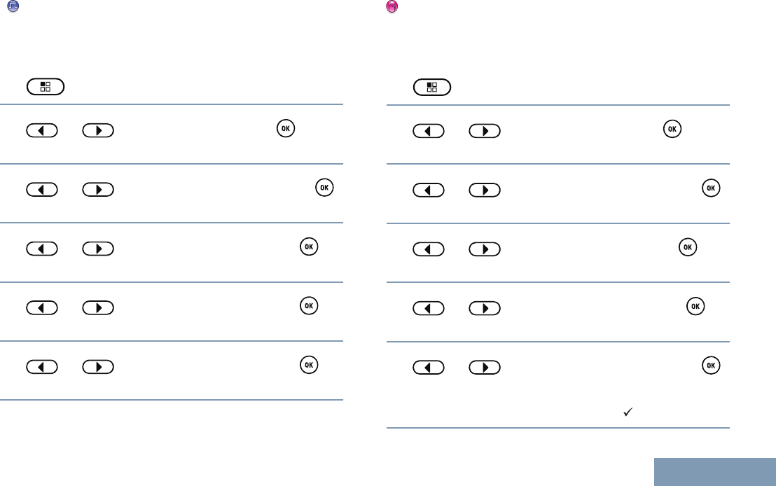
Activating and Deactivating Call Ringers for Private
Calls
You can turn on or off the ringing tones for a received
Private Call.
1 to access the menu.
2 or to Utilities and press to
select.
3 or to Radio Settings and press
to select.
4 or to Tones/Alerts and press to
select.
5 or to Call Ringers and press to
select.
6 or to Private Call and press to
select.
Activating and Deactivating Call Ringers for Selective
Call
You can select, or turn on or off ringing tones for a
received Selective Call.
1 to access the menu.
2 or to Utilities and press to
select.
3 or to Radio Settings and press
to select.
4 or to Tones/Alert and press to
select.
5 or to Call Ringers and press to
select.
6 or to Selective Call and press
to select.
The current tone is indicated by a .
Advanced Features
57
English
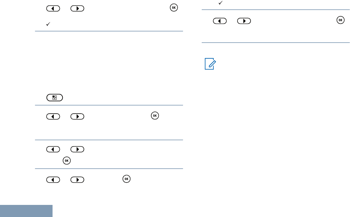
7 or to the required tone and press
to select.
appears beside selected tone.
Assigning Ring Styles
You can program your radio to sound one of ten
predefined ringing tones when receiving a Call Alert
or a Text Message from a particular contact.
The radio sounds out each ring style as you navigate
through the list.
1 to access the menu.
2 or to Contacts and press to
select.
The entries are alphabetically sorted.
3 or to the required alias or ID and
press to select.
4 or to and press to select.
A indicates the current selected tone.
5 or to the required tone and press
to select.
The display shows Contact Saved.
Selecting a Ring Alert Type
Note:
The programmed Ring Alert Type button is
assigned via CPS. Check with your dealer or
system administrator to determine how your
radio has been programmed.
You can program the radio calls to one
predetermined vibrate call. If All Tones status is
disabled, the radio displays the All Tone Mute icon.
If All Tones status is enabled, the related ring alert
type is displayed.
The radio sounds one vibration if it is a momentary
ring style. The radio vibrates repetitively if it is a
repetitive ring style. When set to Ring and Vibrate,
the radio sounds a specific ring tone if there is any
incoming radio transaction (for example, Call Alert or
Message). It sounds like a good key tone or missed
call.
Advanced Features
58
English
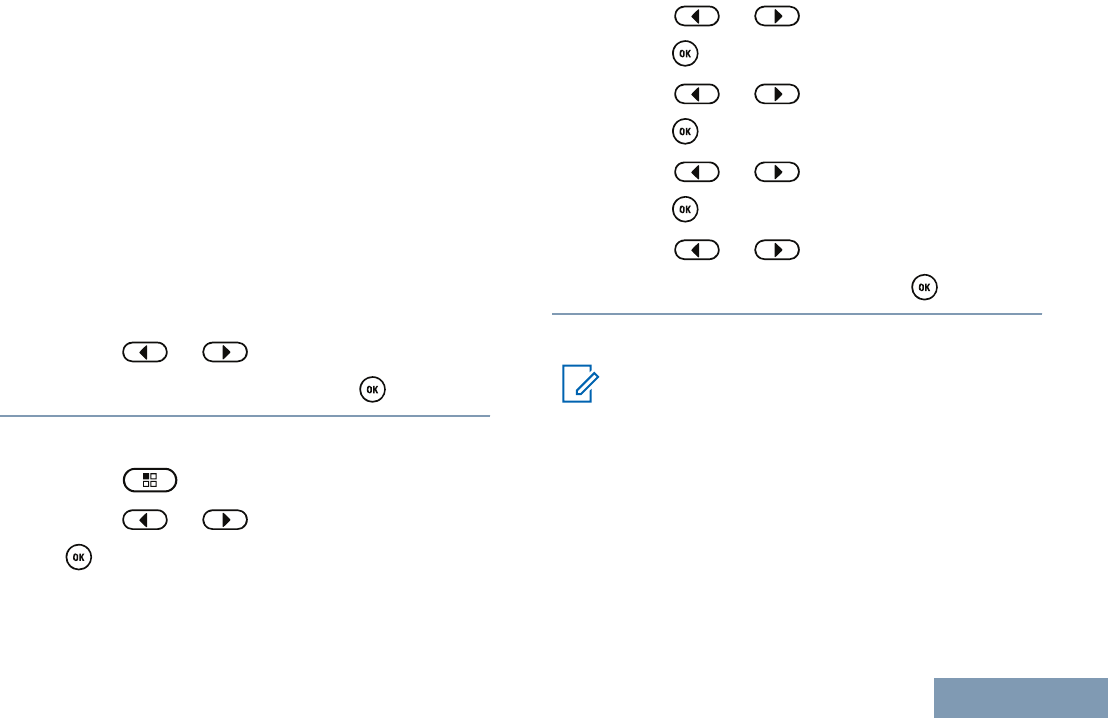
For radios with batteries that support the vibrate
feature and are attached to a vibrating belt clip, the
available Ring Alert Type options are Silent, Ring,
Vibrate, and Ring and Vibrate.
For radios with batteries that do not support the
vibrate feature and are not attached to a vibrating belt
clip, Ring Alert Type is automatically set to Ring. The
available Ring Alert Type options are Silent and Ring.
You can select a Ring Alert Type by performing one
of the following actions.
•Press the programmed Ring Alert Type button to
access the Ring Alert Type menu.
a) Press or to Ring, Vibrate, Ring
& Vibrate or Silent and press to select.
•Access this feature via the menu.
a) Press to access the menu.
b) Press or to Utilities and press
to select.
c) Press or to Radio Settings and
press to select.
d) Press or to Tones/Alerts and
press to select.
e) Press or to Ring Alert Type and
press to select.
f) Press or to Ring, Vibrate, Ring
& Vibrate or Silent and press to select.
Configuring Vibrate Style
Note:
The programmed Vibrate Style button is
assigned via CPS. Check with your dealer or
system administrator to determine how your
radio has been programmed.
Vibrate Style is enabled when the Vibrating Belt Clip
is attached to the radio with a battery that supports
the vibrate feature.
You can configure the vibrate style by performing one
of the following actions.
Advanced Features
59
English
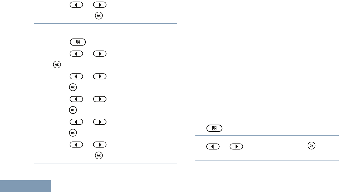
•Press the programmed Vibrate Style button to
access the Vibrate Style menu.
a) Press or to Short, Medium, or
Long and press to select.
•Access this feature via the menu.
a) Press to access the menu.
b) Press or to Utilities and press
to select.
c) Press or to Radio Settings and
press to select.
d) Press or to Tones/Alerts and
press to select.
e) Press or to Vibrate Style and
press to select.
f) Press or to Short, Medium, or
Long and press to select.
Escalating Alarm Tone Volume
You can program your radio to continually alert you
when a radio call remains unanswered. This is done
by automatically increasing the alarm tone volume
over time. This feature is known as Escalert.
Call Log Features
Your radio keeps track of all recent outgoing,
answered, and missed Private Calls. Use the call log
feature to view and manage recent calls.
You can perform the following tasks in each of your
call lists:
• Delete
• View Details
Viewing Recent Calls
The lists are Missed, Answered, and Outgoing.
1 to access the menu.
2 or to Call Log and press to
select.
Advanced Features
60
English
3 or to preferred list and press to
select.
The display shows the most recent entry at the top
of the list.
4 or to view the list.
Press the PTT button to start a Private Call with
the current selected alias or ID.
Deleting a Call from a Call List
1 to access the menu.
2 or to Call Log and press to
select.
3 or to the required list and press
to select.
When you select a call list and it contains no
entries, the display shows List Empty.
4 or to the required alias or ID and
press to select.
5 or to Delete Entry? and press
to select.
6Do one of the following:
•Press to select Yes to delete the entry. The
display shows Entry Deleted.
• or to No, and press the button
to return to the previous screen.
Viewing Details from a Call List
1 to access the menu.
2 or to Call Log and press to
select.
3 or to the required list and press
to select.
Advanced Features
61
English
4 or to the required alias or ID and
press to select.
5 or to View Details and press to
select.
Display shows details.
Call Alert Operation
Call Alert paging enables you to alert a specific radio
user to call you back when they are able to do so.
This feature is applicable for subscriber aliases or IDs
only and is accessible through the menu via Contacts
or manual dial.
Receiving and Responding to a Call Alert
When you receive a Call Alert page, you see the
notification list listing a Call Alert with the alias or ID of
the calling radio on the display.
When you hear a repetitive tone and the LED
blinks yellow, do one of the following:
• Press the PTT button while the display still
shows the Call Alert in the Notification List to
respond with a Private Call.
•Press to exit the Notification List. The
alert is moved to the Missed Call Log.
Making a Call Alert from the Contact List
1 to access the menu.
2 or to Contacts and press to
select.
3 or to the required subscriber alias or
ID and press to select.
4 or to Call Alert and press to
select.
The display shows Call Alert and the
subscriber alias or ID, indicating that the Call Alert
has been sent.
The LED lights up solid green when your radio is
sending the Call Alert.
Advanced Features
62
English

If the Call Alert acknowledgement is received, the
display shows positive mini notice.
If the Call Alert acknowledgement is not received,
the display shows negative mini notice.
Making a Call Alert with the One Touch Access Button
Press the programmed One Touch Access
button to make a Call Alert to the predefined alias
or ID.
The display shows Call Alert and the
subscriber alias or ID, indicating that the Call Alert
has been sent.
The LED lights up solid green when your radio is
sending the Call Alert.
If the Call Alert acknowledgement is received, the
display shows positive mini notice.
If the Call Alert acknowledgement is not received,
the display shows negative mini notice.
Emergency Operation
An Emergency Alarm is used to indicate a critical
situation. You are able to initiate an Emergency at
any time on any screen display even when there is
activity on the current channel.
Your dealer can set the duration of a button press for
the programmed Emergency button, except for long
press, which is similar with all other buttons:
Short press Between 0.05 seconds and 0.75
seconds.
Long press Between 1.00 second and 3.75
seconds.
The Emergency button is assigned with the
Emergency On/Off feature. Check with your dealer for
the assigned operation of the Emergency button.
Note:
If the short press for the Emergency button is
assigned to turn on the Emergency mode,
then the long press for the Emergency button
is assigned to exit the Emergency mode.
If the long press for the Emergency button is
assigned to turn on the Emergency mode,
then the short press for the Emergency button
is assigned to exit the Emergency mode.
Your radio supports three Emergency Alarms:
Advanced Features
63
English

• Emergency Alarm
• Emergency Alarm with Call
•Emergency Alarm with Voice to Follow
Note:
Only one of the Emergency Alarms above can
be assigned to the programmed Emergency
button.
In addition, each alarm has the following types:
•Regular – Radio transmits an alarm signal and
shows audio and/or visual indicators.
•Silent – Radio transmits an alarm signal without
any audio or visual indicators. Radio receives calls
without any sound through the radio’s speaker,
until you press the PTT button to initiate the call.
•Silent with Voice – Radio transmits an alarm
signal without any audio or visual indicators, but
allow incoming calls to sound through the radio’s
speaker.
Sending an Emergency Alarm
This feature allows you to send an Emergency Alarm,
a non-voice signal, which triggers an alert indication
on a group of radios.
If your radio is set to Silent, it does not display any
audio or visual indicators during Emergency mode.
Press the programmed Emergency On button.
The display shows one of the following:
•Tx Alarm and the destination alias.
•Tx Telegram and the destination alias.
The LED lights up solid green and the Emergency
icon appears on the Home screen display.
The Emergency Search Tone sounds. It is
temporarily muted when the radio transmits or
receives voice. The tone stops when the radio
exits Emergency mode.
Note:
The Emergency Search Tone is an optional
feature, it can be enabled or disabled via
CPS. This feature is disabled, if Silent
Emergency is enabled. The CPS can also
program tone to sound to through the
speaker of the radio (default) or wired
accessory. Check with your dealer or
system administrator to determine how
your radio has been programmed.
Advanced Features
64
English

When an Emergency Alarm acknowledgement is
received, the Emergency tone sounds and the
LED blinks green. The display shows Alarm Sent.
If your radio does not receive an Emergency
Alarm acknowledgement, and after all retries have
been exhausted, a tone sounds and the display
shows Alarm Failed.
Radio exits the Emergency Alarm mode and
returns to the Home screen.
Sending an Emergency Alarm with Call
This feature allows you to send an Emergency Alarm
to a group of radios. Upon acknowledgement by a
radio within the group, the group of radios can
communicate over a programmed Emergency
channel.
If your radio is set to Silent, it does not display any
audio or visual indicators during Emergency mode, or
allow any received calls to sound through the speaker
of the radio, until you press the PTT button to initiate
the call.
If your radio is set to Silent with Voice, it does not
display any audio or visual indicators during
Emergency mode, but allow incoming calls to sound
through the speaker of the radio. The indicators only
appear once you press the PTT button to initiate, or
respond to, the call.
1Press the programmed Emergency On button.
The display shows one of the following:
•Tx Alarm and the destination alias.
•Tx Telegram and the destination alias.
The Emergency Search Tone sounds. It is
temporarily muted when the radio transmits or
receives voice. The tone stops when the radio
exits Emergency mode.
Note:
The Emergency Search Tone is an optional
feature, it can be enabled or disabled via
CPS. This feature is disabled, if Silent
Emergency is enabled. The CPS can also
program tone to sound to through the
speaker of the radio (default) or wired
accessory. Check with your dealer or
system administrator to determine how
your radio has been programmed.
When an Emergency Alarm acknowledgement is
received, the Emergency tone sounds and the
Advanced Features
65
English

LED blinks green. The display shows Alarm Sent.
Your radio enters the emergency call mode when
the display shows Emergency and the destination
group alias.
2Hold the radio vertically 1 to 2 inches (2.5 to 5.0
cm) from your mouth.
3Press PTT button to make the call.
The LED lights up solid green and the Group icon
appears on the display.
4Wait for one of the following tones to finish (if
enabled), and speak clearly into the microphone.
• The Talk Permit Tone
•The PTT Sidetone
5Release the PTT button to listen.
If the Channel Free Indication feature is
enabled, you hear a short alert tone the moment
the transmitting radio releases the PTT button,
indicating the channel is free for you to respond.
6Press the PTT button to respond.
7Once your call ends, press Emergency Off button
to exit the Emergency mode.
The radio returns to the Home screen. If you do
not press the Emergency Off button to exit the
Emergency mode, the LED blinks red and the
radio stays in Emergency mode.
Sending an Emergency Alarm with Voice to Follow
This feature allows you to send an Emergency Alarm
to a group of radios. The microphone of your radio is
automatically activated, allowing you to communicate
with the group of radios without pressing the PTT
button.
This activated microphone state is also known as “hot
mic”.
If your radio has Emergency Cycle Mode enabled,
repetitions of hot mic and receiving period are made
for a programmed duration. During Emergency Cycle
Mode, received calls sound through the speaker of
the radio.
If you press the PTT button during the programmed
hot mic transmission or programmed receiving period,
regardless whether Emergency Cycle Mode is
enabled or disabled, you hear a prohibit tone,
indicating that you should release the PTT button.
The radio ignores the PTT press and remains in
Emergency mode.
Advanced Features
66
English

Note:
If you press the PTT button during hot mic,
and continue to press it after the hot mic
duration expires, the radio continues to
transmit until you release the PTT button.
If your radio is set to Silent, it does not display any
audio or visual indicators during Emergency mode, or
allow any received calls to sound through the speaker
of the radio, until the programmed hot mic
transmission period is over, and you press the PTT
button.
If your radio is set to Silent with Voice, it does not
display any audio or visual indicators during
Emergency mode when you are making the call with
hot mic, but allow sound through the speaker of the
radio when the target radio responds after the
programmed hot mic transmission period is over. The
indicators only appear when you press the PTT
button.
Note:
If the Emergency Alarm request fails, the radio
does not retry to send the request, and enters
the hot mic state directly.
1Press the programmed Emergency On button.
The display shows one of the following:
•Tx Alarm and the destination alias.
•Tx Telegram and the destination alias.
The LED lights up solid green and the Emergency
icon is displayed.
The Emergency Search Tone sounds. It is
temporarily muted when the radio transmits or
receives voice. The tone stops when the radio
exits Emergency mode.
Note:
The Emergency Search Tone is an optional
feature, it can be enabled or disabled via
CPS. This feature is disabled, if Silent
Emergency is enabled. The CPS can also
program tone to sound to through the
speaker of the radio (default) or wired
accessory. Check with your dealer or
system administrator to determine how
your radio has been programmed.
2Once the display shows Alarm Sent, speak
clearly into the microphone.
When hot mic has been enabled, the radio
automatically transmits without a PTT button press
Advanced Features
67
English
until the hot mic duration expires. While
transmitting, the LED lights up solid green and the
Emergency icon appears on the display.
3The radio automatically stops transmitting when
the cycling duration between hot mic and receiving
calls expires, if Emergency Cycle Mode is
enabled.
4Once the hot mic duration expires, the radio
automatically stops transmitting. The LED blinks
red and the radio remains in Emergency mode. To
transmit again, press the PTT button.
Reinitiating an Emergency Mode
Note:
This feature is only applicable to the radio
sending the Emergency Alarm.
There are two instances where this can happen:
• You change the channel while the radio is in
Emergency mode. This exits the Emergency
mode. If Emergency Alarm is enabled on this new
channel, the radio reinitiates Emergency.
• You press the programmed Emergency On
button during an Emergency initiation/transmission
state. This causes the radio to exit this state, and
to reinitiate Emergency.
Exiting Emergency Mode After Sending the Emergency
Alarm
Your radio exits Emergency mode when one of the
following occurs:
• Emergency Alarm acknowledgement is received
(for Emergency Alarm only).
• All retries to send the alarm have been exhausted.
• The Emergency Off button is pressed.
Note:
If your radio is powered off, it exits the
Emergency mode. The radio will not reinitiate
the Emergency mode automatically when it is
turned on again.
Privacy
If enabled, this feature helps to prevent
eavesdropping by unauthorized users on a channel
by the use of a software-based scrambling solution.
The signaling and user identification portions of a
transmission are not scrambled.
Advanced Features
68
English

Your radio must have privacy enabled on the channel
to send a privacy-enabled transmission, although this
is not a necessary requirement for receiving a
transmission. While on a privacy-enabled channel,
the radio is still able to receive clear (unscrambled)
transmissions.
Your radio supports two types of privacy:
• Basic Privacy.
• Enhanced Privacy.
Only one of the privacy types above can be assigned
to the radio.
To unscramble a privacy-enabled call or data
transmission, your radio must be programmed to
have the same Privacy Key (for Basic Privacy), or the
same Key Value and Key ID (for Enhanced Privacy)
as the transmitting radio.
If your radio receives a scrambled call that is of a
different Privacy Key, or a different Key Value and
Key ID, you will either hear a garbled transmission
(Basic Privacy) or nothing at all (Enhanced Privacy).
Note:
This feature is not applicable in Citizens Band
channels that are in the same frequency.
If the radio has a privacy type assigned, the Home
screen shows the Secure or Unsecure icon, except
when the radio is sending or receiving an Emergency
call or alarm.
The LED lights up solid green while the radio is
transmitting and blinks green rapidly when the radio is
receiving an ongoing privacy-enabled transmission.
You can access this feature by performing one of the
following actions:
• Pressing the programmed Privacy button to
toggle privacy on or off.
• Using the Radio Menu as described by the steps
described next.
Note:
Some radio models may not offer this Privacy
feature. Check with your dealer or system
administrator for more information.
1 to access the menu.
2 or to Utilities and press to
select.
Advanced Features
69
English
3 or to Radio Settings and press
to select.
4 or to Privacy and press to
select.
You can also use or to change
selected option.
5Press to enable/disable Privacy.
The display shows beside Enabled.
The disappears from beside Enabled.
Security
You can enable or disable any radio in the system.
For example, you might want to disable a stolen
radio, to prevent the thief from using it, and enable
that radio, when it is recovered.
Note:
Performing Radio Disable and Enable is
limited to radios with these functions enabled.
Check with your dealer or system
administrator for more information.
Radio Disable
1Access this feature by
Radio
Con-
trols
Steps
Radio
Disable
button
1Press the programmed Radio Disa-
ble button.
2 or to the required alias
or ID and press to select.
Radio
menu 1 to access the menu.
2 or to Contacts and
press to select. The entries are
alphabetically sorted.
3Use one of the steps described next
to select the required subscriber
alias or ID:
Advanced Features
70
English
Radio
Con-
trols
Steps
• Select the required alias or ID di-
rectly.
• or to the re-
quired alias or ID and press
to select.
•Use the Manual Dial menu.
• or to Manual
Dial and press to select.
• or to Radio
Number and press to se-
lect.
• The first line of the display
shows Radio Number:. The
second line of the display
shows a blinking cursor. Use
Radio
Con-
trols
Steps
the keypad to enter the sub-
scriber alias or ID and press
.
4 or to Radio Disable
and press to select.
The display shows Radio Enable: <Subscriber
Alias or ID> and the LED lights up solid green.
2Wait for acknowledgement.
If successful, the radio sounds a positive indicator
tone and the display shows positive mini notice.
If not successful, the radio sounds a negative
indicator tone and the display shows negative mini
notice.
Do not press during the Radio Disable
operation as you will not get an acknowledgement
message.
Advanced Features
71
English
Radio Enable
1Access this feature by
Radio
Con-
trols
Steps
Radio
Enable
button
1Press the programmed Radio Ena-
ble button.
2 or to the required alias
or ID and press to select.
Radio
menu 1 to access the menu.
2 or to Contacts and
press to select. The entries are
alphabetically sorted.
3Use one of the steps described next
to select the required subscriber
alias or ID
• Select the required alias or ID di-
rectly.
Radio
Con-
trols
Steps
• or to the re-
quired alias or ID and press
to select.
•Use the Manual Dial menu.
• or to Manual
Dial and press to select.
• or to Radio
Number and press to se-
lect.
• The first line of the display
shows Radio Number:. The
second line of the display
shows a blinking cursor. Use
the keypad to enter the sub-
scriber alias or ID and press
.
Advanced Features
72
English
Radio
Con-
trols
Steps
4 or to Radio Enable
and press to select.
The display shows Radio Enable: <Subscriber
Alias or ID> and the LED lights up solid green.
2Wait for acknowledgement.
If successful, the radio sounds a positive indicator
tone and the display shows positive mini notice.
If not successful, the radio sounds a negative
indicator tone and the display shows negative mini
notice.
Do not press during the Radio Enable
operation as you will not get an acknowledgement
message.
Lone Worker
This feature raises an emergency if there is no user
activity, such as any radio button press or activation
of the channel selector, for a predefined time.
Before raising the emergency, when the inactivity
timer expires, the radio warns the user via an audio
indicator.
If there is still no acknowledgement by the user
before the predefined reminder timer expires, the
radio initiates an Emergency Alarm.
Only one of the following Emergency Alarms can be
assigned to this feature:
• Emergency Alarm
• Emergency Alarm with Call
•Emergency Alarm with Voice to Follow
The radio remains in the emergency state allowing
voice messages to proceed until action is taken. See
Emergency Operation on page 63 on ways to exit
Emergency.
Advanced Features
73
English
Note:
This feature is limited to radios with this
function enabled. Check with your dealer or
system administrator for more information.
Password Lock Features
If enabled, this feature only allows you access your
radio if the correct password is entered upon
powering up.
Accessing the Radio from Password
1Power up your radio.
You hear a continuous tone.
2Enter your current four-digit password. Press or to
edit each digit’s numeric value. Each digit changes
to . Press to move to next digit. Press to
confirm your selection.
• Enter your current four-digit password with the
radio’s keypad. The second line of the display
shows . Press to proceed.
• Enter your current four-digit password. Press
or to edit each digit’s numeric
value. Each digit changes to . Press to move
to next digit. Press to confirm your
selection.
You hear a positive indicator tone for every digit
entered. Press to remove the last digit on the
display.
If the password is correct, your radio proceeds to
power up. See Powering Up the Radio on page
17.
If the password is incorrect, the display shows
Wrong Password. Repeat Steps 1 and 2.
After the third incorrect password, the display
shows Wrong Password and then, shows Radio
Locked. A tone sounds and the LED double blinks
yellow.
Your radio enters into locked state for 15 minutes,
and responds to inputs from On/Off/Volume
Control Knob only.
Note:
The radio is unable to receive any call,
including emergency calls, in locked state.
Advanced Features
74
English
Unlocking the Radio from Locked State
1If your radio was powered down after being in the
locked state, power up the radio.
A tone sounds and the LED double blinks yellow.
The display shows Radio Locked.
2Wait for 15 minutes.
Your radio restarts the 15 minutes timer for locked
state when you power up.
3Repeat Steps 1 and 2 in Accessing the Radio from
Password on page 74.
Turning the Password Lock On or Off
1 to access the menu.
2 or to Utilities and press to
select.
3 or to Radio Settings and press
to select.
4 or to Passwd Lock and press to
select.
5Enter the four-digit password.
See Step 2 in Accessing the Radio from Password
on page 74.
6Press to proceed.
If the password is incorrect, the display shows
Wrong Password, and automatically returns to the
previous menu.
7If the password entered in the previous step is
correct, press to enable/disable password
lock.
The display shows beside Enabled.
The disappears from beside Enabled.
Changing the Password
1 to access the menu.
Advanced Features
75
English
2 or to Utilities and press to
select.
3 or to Radio Settings and press
to select.
4 or to Passwd Lock and press to
select.
5Enter the four-digit password.
See Step 2 in Accessing the Radio from Password
on page 74.
6Press to proceed.
If the password is incorrect, the display shows
Wrong Password, and automatically returns to the
previous menu.
7If the password entered in the previous step is
correct, or to Change Pwd and press
to select.
8Enter a new four-digit password.
See Step 2 in Accessing the Radio from Password
on page 74.
9Reenter the previously entered four-digit
password. See Step 2 in Accessing the Radio
from Password on page 74.
10 Press to proceed.
If the reentered password matches the new
password entered earlier, the display shows
Password Changed.
If the reentered password does NOT match the
new password entered earlier, the display shows
Passwords Do Not Match.
The screen automatically returns to the previous
menu.
Notification List
Your radio has a Notification List that collects all your
“unread” events on the channel, such as unread text
messages, missed calls, and call alerts.
The Notification icon appears on the status bar when
the Notification List has one or more events.
Advanced Features
76
English
The list supports a maximum of forty (40) unread
events. When it is full, the next event automatically
replaces the oldest event.
Note:
After the events are read, they are removed
from the Notification List.
Accessing the Notification List
1 to access the menu.
2 or to Notification and press to
select.
3 or to the required event and press
to select.
Long press to return to the Home Screen.
Auto-Range Transponder System (ARTS)
ARTS is an analog-only feature designed to inform
you when your radio is out-of-range of other ARTS-
equipped radios.
ARTS-equipped radios transmit or receive signals
periodically to confirm that they are within range of
each other. Your dealer can program your radio to
transmit or receive the ARTS signal.
Your radio provides indications of states as follows:
•First-Time Alert – A tone sounds and the display
shows In Range after the channel alias.
•ARTS-in-Range Alert – A tone sounds, if
programmed, and the display shows In Range
after the channel alias.
•ARTS-Out-of-Range Alert – A tone sounds, the
LED rapidly blinks red, and the display alternates
between Out of Range and the home screen.
Over-the-Air-Programming (OTAP)
Your radio can be updated by your dealer remotely,
via OTAP, without needing to be physically
connected. Additionally, some settings can also be
configured via OTAP.
While undergoing OTAP, the LED blinks green.
Advanced Features
77
English

Note:
When the radio is receiving high volume data,
the High Volume Data icon appears and
channel is busy. A PTT button press at this
time may cause a negative tone to sound.
Once the programming is complete, depending on
your radio’s configuration:
•A tone sounds, the display shows Updating
Restarting, and your radio restarts (powers off
and on again).
•Select between Restart Now or Postpone.
Selecting Postpone allows your radio to return to
the previous display, with an OTAP Timer icon
visible, for a period of time before the automatic
restart occurs.
Upon power up after the automatic restart occurs, the
display shows Sw Update Completed if the OTAP
update is successful or Sw Update Failed if the
OTAP update is unsuccessful.
See Software Update on page 94 for your updated
software version.
Wi-Fi Operation
Wi-Fi® is a registered trademark of Wi-Fi Alliance®.
Note:
This feature is applicable to XPR 3500e only.
This feature allows you to setup and connect to a Wi-
Fi® network. Wi-Fi supports updates of radio
firmware, codeplug, and resources such as language
packs and voice announcement.
Turning Wi-Fi On or Off
Note:
This feature is applicable to XPR 3500e only.
The programmed Wi-Fi On or Off button is
assigned via CPS. Check with your dealer or
system administrator to determine how your
radio has been programmed.
You can turn on or turn off Wi-Fi® by performing one
of the following actions.
•Press the programmed Wi-Fi On or Off button.
Voice Announcement sounds Turning On Wi-Fi or
Turning Off Wi-Fi.
•Access this feature via the menu.
a) Press to access the menu.
Advanced Features
78
English
b) Press or to WiFi and press to
select.
c) Press or to Turn On and press
to select.
The radio displays Turning On WiFi.
Connecting to a Network Access Point
Note:
This feature is applicable to XPR 3500e only.
When you turn on Wi-Fi®, the radio scans and
connects to a network access point.
Viewing Details of Network Access Points
Note:
This feature is applicable to XPR 3500e only.
Perform the following actions to view details of
network access points.
1Press to access the menu.
2Press or to WiFi and press to
select.
3Press or to a network access point
and press to select.
4Press or to view Network SSID,
Security Mode, IP Address, and MAC Address.
For a non-connected network access point, only
the Service Set Identifier (SSID) and Security
Mode are displayed.
Utilities
Setting the Squelch Level
You can adjust your radio's squelch level to filter out
unwanted calls with low signal strength or channels
that have a higher than normal background noise.
Normal is the default. Tight filters out (unwanted)
calls and/or background noise; however, calls from
remote locations may also be filtered out.
Note:
This feature is not applicable in Citizens Band
channels that are in the same frequency.
Advanced Features
79
English
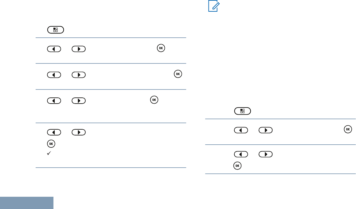
Press the programmed Squelch button to toggle
squelch level between normal and tight. Follow the
procedure described next to access this feature via
the radio’s menus.
1 to access the menu.
2 or to Utilities and press to
select.
3 or to Radio Settings and press
to select.
4 or to Squelch and press to
select.
The display shows Tight and Normal.
5 or to the required setting and press
to select.
appears besides selected setting. Screen
returns to the previous menu.
Setting the Power Level
Note:
This feature is not applicable in Citizens Band
channels that are in the same frequency.
You can customize the power setting of the radio to
high or low for each channel.
High enables communication with radios located at a
considerable distance from you. Low enables
communication with radios in closer proximity.
Press the programmed Power Level button to toggle
transmit power level between high and low. Follow
the procedure described next to access this feature
via the radio menu.
1Press to access the menu.
2Press or to Utilities and press
to select.
3Press or to Radio Settings and
press to select.
Advanced Features
80
English
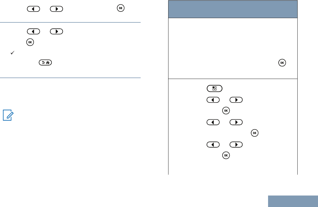
4Press or to Power and press to
select.
5Press or to the required setting and
press to select.
appears beside selected setting. At any time,
long press to return to the Home screen.
Screen returns to the previous menu.
Adjusting the Display Brightness
You can adjust the display brightness of the radio as
needed.
Note:
Display brightness cannot be adjusted when
Auto Brightness is enabled.
Adjust the Display Brightness by performing one of
the following actions:
Radio
Control
Steps
Program-
med Dis-
play
Bright-
ness
Button
1Press the programmed Bright-
ness button.
2Decrease display brightness by
pressing or increase the display
brightness by pressing . Select
from setting of 1 to 8. Press to
confirm your entry.
Menu 1 to access the menu.
2 or to Utilities and
press to select.
3 or to Radio Set‐
tings and press to select.
4 or to Brightness and
press to select.
The display shows a progress bar.
Advanced Features
81
English
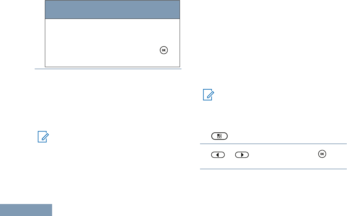
Radio
Control
Steps
5Decrease display brightness by
pressing or increase the display
brightness by pressing . Select
from setting of 1 to 8. Press to
confirm your entry.
Turning the Voice Operating Transmission (VOX)
Feature On or Off
This feature allows you to initiate a hands-free voice
activated call on a programmed channel. The radio
automatically transmits, for a programmed period,
whenever the microphone on the VOX-capable
accessory detects voice.
Note:
This feature is not applicable in Citizens Band
channels that are in the same frequency.
Pressing the PTT button during radio operation will
disable VOX. To re-enable VOX, do one of the
following:
• Turn the radio off and power it on again.
• Change the channel via the Channel Selector
Knob.
• Press the programmed VOX button to toggle the
feature on or off.
• Follow the steps described next to access this
feature via the radio menu.
If the Talk Permit Tone feature is enabled (see
Turning the Talk Permit Tone On or Off on page
85), use a trigger word to initiate the call. Wait for
the Talk Permit Tone to finish before speaking clearly
into the microphone.
Note:
Turning this feature on or off is limited to
radios with this function enabled. Check with
your dealer or system administrator for more
information.
1 to access the menu.
2 or to Utilities and press to
select.
Advanced Features
82
English
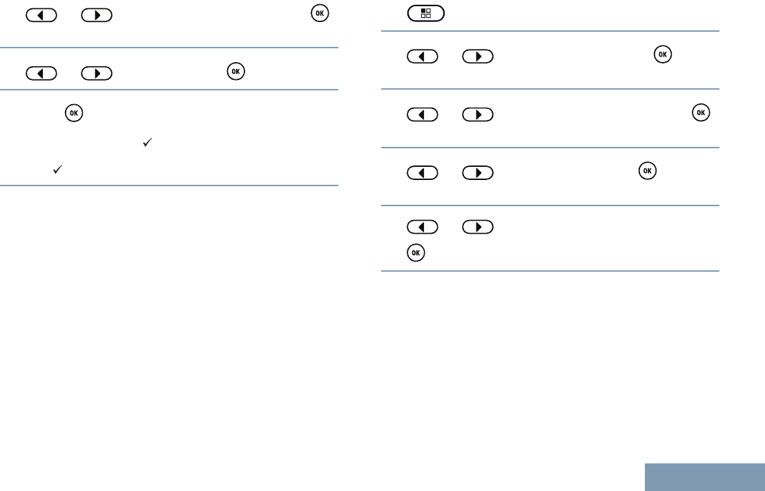
3 or to Radio Settings and press
to select.
4 or to VOX and press to select.
5Press to disable/enable VOX.
The display shows beside Enabled.
The disappears from beside Enabled.
Setting the Display Backlight Timer
You can set the the radio’s display backlight timer as
needed. The setting also affects the Menu Navigation
Buttons and keypad backlighting accordingly.
Press the programmed Backlight button to toggle the
backlight settings, or follow the procedure described
next to access this feature via the radio menu.
The display backlight and keypad backlighting are
automatically turned off if the LED indicator is
disabled (see Turning the LED Indicator On or Off on
page 86).
1 to access the menu.
2 or to Utilities and press to
select.
3 or to Radio Settings and press
to select.
4 or to Display and press to
select.
5 or to Backlight Timer and press
to select.
Turning the Radio Tones/Alerts On or Off
You can enable and disable all radio tones and alerts
(except for the incoming Emergency alert tone) if
needed.
Press the programmed All Tones/Alerts button to
toggle all tones on or off, or follow the procedure
described next to access this feature via the radio
menu.
Advanced Features
83
English
1 to access the menu.
2 or to Utilities and press to
select.
3 or to Radio Settings and press
to select.
4 or to Tones/Alerts and press to
select.
5 or to All Tones and press to
select.
You can also use or to change the
selected option.
6Press to enable/disable all tones and alerts.
The display shows beside Enabled.
The disappears from beside Enabled.
Turning the Power Up Alert Tone On or Off
You can enable and disable the Power Up Alert Tone
if needed.
1 to access the menu.
2 or to Utilities and press to
select.
3 or to Radio Settings and press
to select.
4 or to Tones/Alerts and press to
select.
5 or to Power Up and press to
select.
You can also use or to change the
selected option.
6Press to enable/disable the Power Up Alert
Tone.
Advanced Features
84
English
The display shows beside Enabled.
The disappears from beside Enabled.
Setting the Tone Alert Volume Offset Level
You can adjust the Tone Alert Volume Offset level if
needed. This feature adjusts the volume of the tones/
alerts, allowing it to be higher or lower than the voice
volume.
1 to access the menu.
2 or to Utilities and press to
select.
3 or to Radio Settings and press
to select.
4 or to Tones/Alerts and press to
select.
5 or to Vol. Offset and press to
select.
6 or to the required volume value.
The radio sounds a feedback tone with each
corresponding volume value.
7Do one of the following:
•Press to keep the required displayed
volume value.
•Press to exit without changing the
current volume offset settings.
• Repeat Step 6 to select another volume value.
Turning the Talk Permit Tone On or Off
You can enable and disable the Talk Permit Tone if
needed.
1 to access the menu.
2 or to Utilities and press to
select.
3 or to Radio Settings and press
to select.
Advanced Features
85
English
4 or to Tones/Alerts and press to
select.
5 or to Talk Permit and press to
select.
6Press to enable/disable the Talk Permit Tone.
The display shows beside Enabled.
The disappears from beside Enabled.
Language
You can set your radio display to be in your required
language.
1 to access the menu.
2 or to Utilities and press to
select.
3 or to Radio Settings and press
to select.
4 or to Languages and press to
select.
You can also use or to change
selected option.
5 or to the required language and press
to enable. appears beside selected
language.
Turning the LED Indicator On or Off
You can enable and disable the LED Indicator if
needed.
1 to access the menu.
2 or to Utilities and press to
select.
3 or to Radio Settings and press
to select.
Advanced Features
86
English
4 or to LED Indicator and press
to select.
You can also use or to change the
selected option.
5Press to enable/disable the LED Indicator.
The display shows beside Enabled.
The disappears from beside Enabled.
Turning the Introduction Screen On or Off
You can enable and disable the Introduction Screen if
needed.
1 to access the menu.
2 or to Utilities and press to
select.
3 or to Radio Settings and press
to select.
4 or to Display and press to
select.
5 or to Intro Screen and press to
select.
You can also use or to change the
selected option.
6Press to enable/disable the Introduction
Screen.
The display shows beside Enabled.
The disappears from beside Enabled.
Turning the Voice Announcement On or Off
Note:
The Voice Announcement feature can only be
enabled via the MOTOTRBO CPS. If enabled,
the Text-to-Speech feature is automatically
disabled, and vice versa.
This feature enables the radio to audibly indicate the
current Zone or Channel the user has assigned, or
programmable button press. This audio indicator can
Advanced Features
87
English
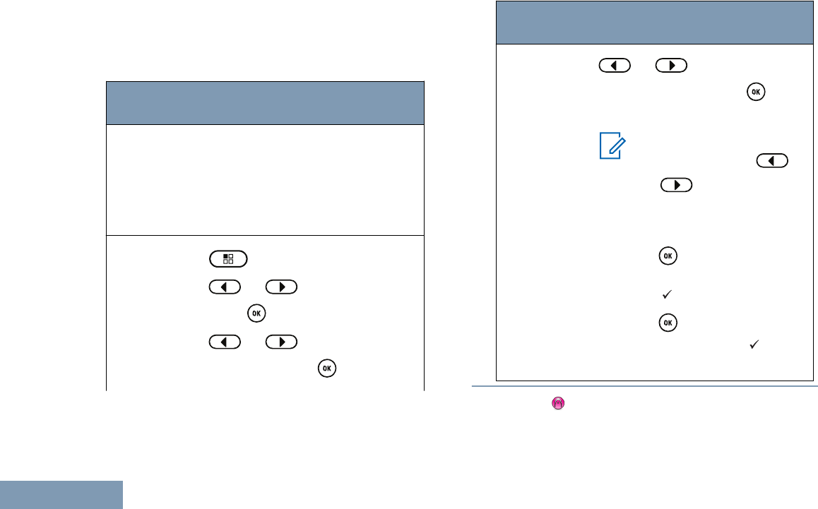
be customized per customer requirements. This is
typically useful when the user is in a difficult condition
to read the content shown on the display.
Toggle Voice Announcement On or Off.
Radio
Control
Steps
Program-
med Voice
An-
nounce-
ment But-
ton
Press the programmed Voice An-
nouncement button.
Menu 1 to access the menu.
2 or to Utilities and
press to select.
3 or to Radio Set‐
tings and press to select.
Radio
Control
Steps
4 or to Voice An‐
nouncement and press to se-
lect.
Note:
You can also use
or to change the
selected option.
5Do one of the following:
•Press to enable Voice An-
nouncement. The display
shows beside Enabled.
•Press to disable Voice
Announcement. The disap-
pears from beside Enabled.
Call Forwarding
You can enable your radio to automatically forward
voice calls to another radio.
Advanced Features
88
English
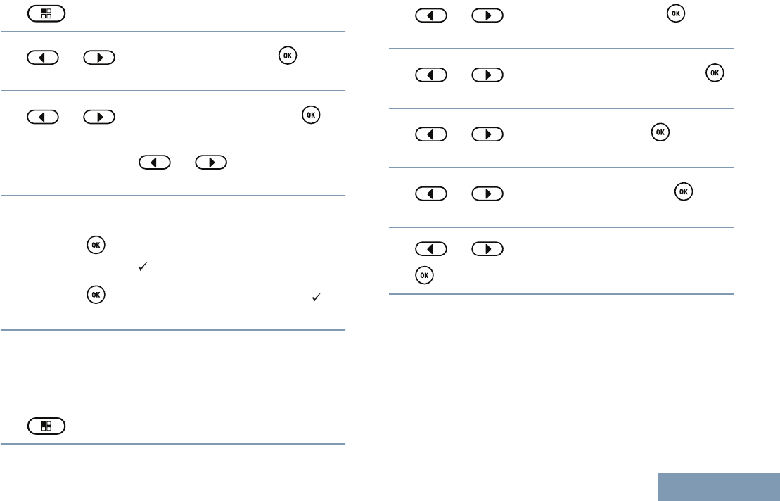
1 to access the menu.
2 or to Utilities and press to
select.
3 or to Call Forward and press to
select.
You can also use or to change the
selected option.
4Do one of the following:
•Press to enable Call Forwarding. The
display shows beside Enabled.
•Press to disable Call Forwarding. The
disappears from beside Enabled.
Menu Timer
Set the period of time your radio stays in the menu
before it automatically switches to the Home screen.
1 to access the menu.
2 or to Utilities and press to
select.
3 or to Radio Settings and press
to select.
4 or to Display and press to
select.
5 or to Menu Timer and press to
select.
6 or to the required setting and press
to select.
Analog Mic AGC (Mic AGC-A)
This feature controls the your radio's microphone gain
automatically while transmitting on an analog system.
It suppresses loud audio or boosts soft audio to a
preset value in order to provide a consistent level of
audio.
Advanced Features
89
English
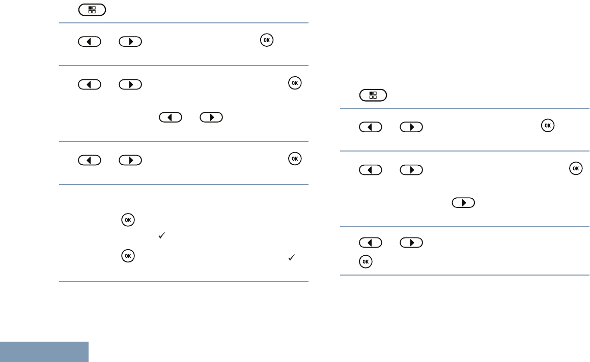
1 to access the menu.
2 or to Utilities and press to
select.
3 or to Radio Settings and press
to select.
You can also use or to change the
selected option.
4 or to Analog Mic AGC and press
to select.
5Do one of the following:
•Press to enable Analog Mic AGC. The
display shows beside Enabled.
•Press to disable Analog Mic AGC. The
disappears from beside Enabled.
Digital Mic AGC (Mic AGC-D)
This feature controls the your radio's microphone gain
automatically while transmitting on a digital system. It
suppresses loud audio or boosts soft audio to a
preset value in order to provide a consistent level of
audio.
1 to access the menu.
2 or to Utilities and press to
select.
3 or to Radio Settings and press
to select.
You can also use or to change the selected
option.
4 or to Digital Mic AGC and press
to select.
5Do one of the following:
Advanced Features
90
English
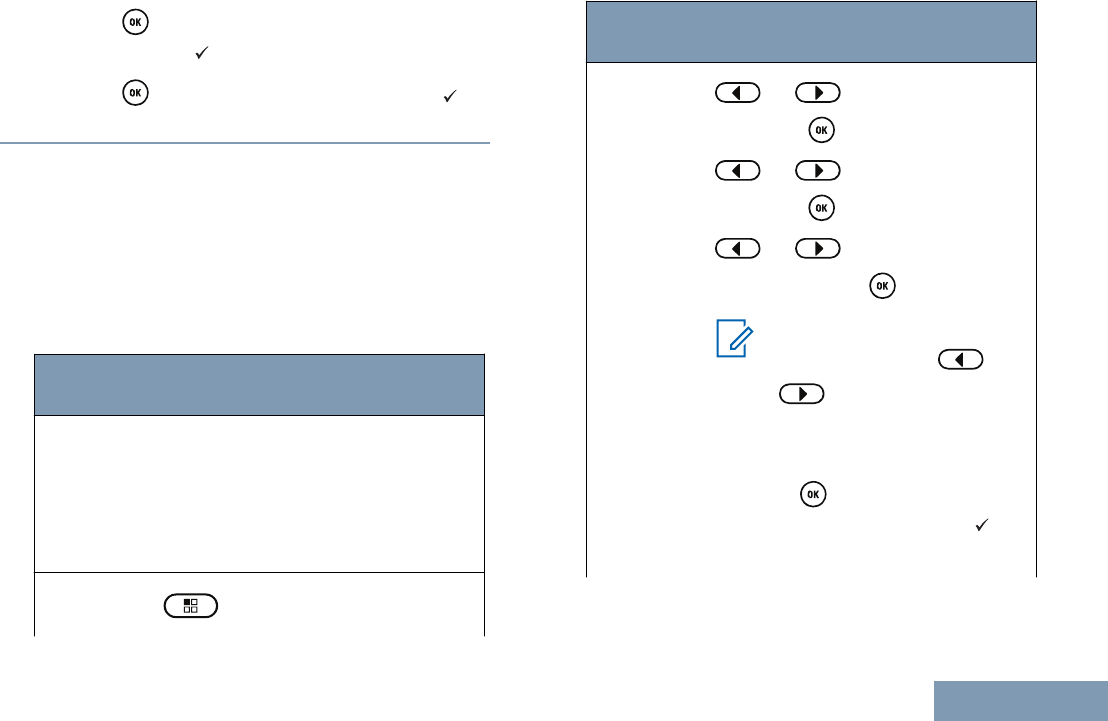
•Press to enable Digital Mic AGC. The
display shows beside Enabled.
•Press to disable Digital Mic AGC. The
disappears from beside Enabled.
Intelligent Audio
Your radio can automatically adjust its audio volume
to overcome background noise in the environment,
inclusive of all stationary and non-stationary noise
sources. This feature is a Receive-only feature and
does not affect Transmit audio.
Toggle Intelligent Audio On or Off.
Radio
Control
Steps
Pro-
gram-
med In-
telligent
Audio
Button
Press the programmed Intelligent Au-
dio button.
Menu 1 to access the menu.
Radio
Control
Steps
2 or to Radio Settings
and press to select.
3 or to Radio Settings
and press to select.
4 or to Intelligent
Audio and press to select.
Note:
You can also use or
to change the select-
ed option.
5Do one of the following:
•Press to enable Intelligent
Audio. The display shows be-
side Enabled.
Advanced Features
91
English
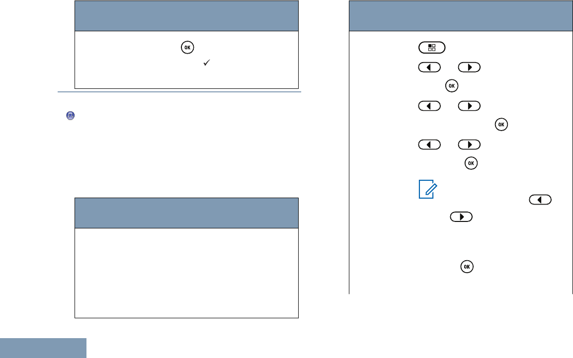
Radio
Control
Steps
•Press to disable Intelligent
Audio. The disappears from
beside Enabled.
Turning the Acoustic Feedback Suppressor Feature On
or Off
This feature allows you to minimize acoustic feedback
in received calls.
Toggle the Acoustic Feedback Suppressor
Feature On or Off by performing one of the
following actions:
Radio
Control
Steps
Program-
med
Acoustic
Feedback
Suppres-
sor But-
ton
Press the programmed Acoustic
Feedback Suppressor button.
Radio
Control
Steps
Menu 1 to access the menu.
2 or to Utilities and
press to select.
3 or to Radio Set‐
tings and press to select.
4 or to AF Suppressor
and press to select.
Note:
You can also use or
to change the se-
lected option.
5Do one of the following:
•Press to enable Acoustic
Feedback Suppressor. The
Advanced Features
92
English
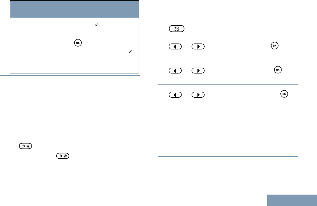
Radio
Control
Steps
display shows beside Ena-
bled.
•Press to disable Acoustic
Feedback Suppressor. The
disappears from beside Ena-
bled.
Accessing General Radio Information
Your radio contains information on the following:
• Battery
• Radio Alias and ID
• Firmware and Codeplug Versions
• GPS Information
• Software Update
Press at any time to return to the previous
screen or long press to return to the Home
screen. The radio exits the current screen once the
inactivity timer expires.
Accessing the Battery Information
Displays information on your radio battery.
1 to access the menu.
2 or to Utilities and press to
select.
3 or to Radio Info and press to
select.
4 or to Battery Info and press to
select.
The display shows the battery information.
For IMPRES batteries ONLY: The display reads
Recondition Battery if the battery requires
reconditioning in an IMPRES charger. After the
reconditioning process, the display then shows the
battery information.
Checking the Radio Alias and ID
This feature displays the ID of your radio.
Advanced Features
93
English
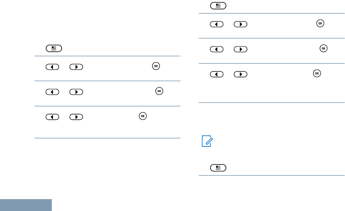
Press the programmed Radio Alias and ID button to
check your radio alias and ID. You hear a positive
indicator tone.
Follow the procedure described next to access this
feature via the radio screen.
1 to access the menu.
2 or to Utilities and press to
select.
3 or to Radio Info and press to
select.
4 or to My ID and press to select.
The first line of the display shows the radio alias.
The second line of the display shows the radio ID.
You can also press the programmed Radio Alias and
ID button to return to the previous screen.
Checking the Firmware Version and Codeplug
Version
Displays the firmware version on your radio.
1 to access the menu.
2 or to Utilities and press to
select.
3 or to Radio Info and press to
select.
4 or to Versions and press to
select.
The display shows the current firmware and
codeplug versions.
Software Update
Displays the date and time of the latest software
update carried out via Over-the-Air Programming.
Note:
Software Update menu is only available after
at least one successful OTAP session.
1 to access the menu.
Advanced Features
94
English
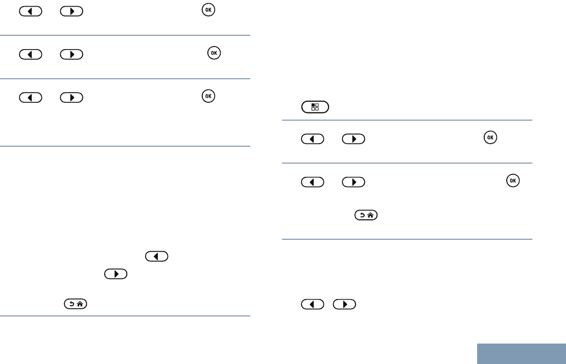
2 or to Utilities and press to
select.
3 or to Radio Info and press to
select.
4 or to SW Update and press to
select.
The display shows the date and time of the latest
software update.
See Over-the-Air-Programming (OTAP) on page 77
for details on OTAP session.
Checking the RSSI Values
Your radio shows the Received Signal Strength
Indicator (RSSI) icon at the top of your display. This
feature allows you to view the RSSI values.
On the home screen, press three times and
immediately press , all within 5 seconds.
The display shows current RSSI values. Long
press the to return to the Home Screen.
See Display Icons on page 28 for details on RSSI
icon.
Front Panel Configuration (FPC)
Your radio is able to customize certain feature
parameters to enhance the use of your radio.
Entering FPC Mode
1 to access the menu.
2 or to Utilities and press to
select.
3 or to Program Radio and press
to select.
Long press at any time to return to the
Home screen.
Editing FPC Mode Parameters
Use the following buttons as required while navigating
through the feature parameters:
•, – Scroll through options, increase/
decrease values, or navigate vertically.
Advanced Features
95
English

• – Select the option or enter a sub-menu.
• – Short-press to return to previous menu or
to exit the selection screen. Long-press to return
to Home screen.
Advanced Features
96
English

Authorized Accessories List
Antennas
• VHF, 136 – 155 MHz, Helical Antenna
(PMAD4117_)
• VHF, 144 – 165 MHz, Helical Antenna
(PMAD4116_)
• VHF, 152 – 174 MHz, Helical Antenna
(PMAD4118_)
• VHF, 136 – 148 MHz, Stubby Antenna
(PMAD4119_)
• VHF, 146 – 160 MHz, Stubby Antenna
(PMAD4120_)
• VHF, 160 – 174 MHz, Stubby Antenna
(PMAD4121_)
• UHF, 403 – 450 MHz, Stubby Antenna
(PMAE4069_)
• UHF, 440 – 490 MHz, Stubby Antenna
(PMAE4070_)
• UHF, 470 – 527 MHz, Stubby Antenna
(PMAE4071_)
• UHF, 403 – 527 MHz, Slim Whip Antenna
(PMAE4079_)
Batteries
• Core Slim Li-Ion, 1600 mAh IP56 Battery
(PMNN4406_R)
• IMPRES Slim Li-Ion, 1600 mAh IP56 Battery
(PMNN4407_R)
• IMPRES Li-Ion Non-FM, 2250 mAh IP56 Battery
(PMNN4409_R)
• Li-Mn 1400 mAh low temp -30C battery
Submersible (IP67) (PMNN4435_R) [7]
• Battery Li-Ion, IP57 2050 mAh (PMNN4463_) [7]
• IMPRES Slim Li-Ion, 2100 mAh IP68 Battery
(PMNN4491_)
• IMPRES Li-Ion, 3000 mAh IP68 Battery, low
voltage (PMNN4493_)
• IMPRES Li-Ion, 3000 mAh IP68 Battery for
Vibrating Belt Clip (PMNN4488_)
• IMPRES Li-Ion, 2900 mAh TIA4950 HAZLOC IP68
Battery (PMNN4490_)[6]
Authorized Accessories List
97
English

Carry Devices
• Belt Clip for 2-Inch Belt Width (PMLN4651_)
• Belt Clip for 2.5-Inch Belt Width (PMLN7008_)
• 2.5-Inch Replacement Leather Swivel Belt Loop
(PMLN5610_)
• 3-Inch Replacement Leather Swivel Belt Loop
(PMLN5611_)
• Leather Radio Strap (RLN6486_) [8]
• Leather Radio Strap, Size XL (RLN6487_) [8]
• Anti-Sway Leather Radio Strap (RLN6488_) [8]
• Hard Leather Carry Case with 3-Inch Fixed Belt
Loop for Limited Keypad Radio (PMLN5863_)
• Hard Leather Carry Case with 3-Inch Swivel Belt
for Limited Keypad Radio (PMLN5865_)
• Hard Leather Carry Case with 2.5-Inch Swivel Belt
Loop for Limited Keypad Radio (PMLN5867_)
• Nylon Carry Case with 3-Inch Fixed Belt Loop for
Limited Keypad Radio (PMLN5869_)
• Vibrating Belt Clip for 2.5-Inch Belt Width
(PMLN7296_)
Chargers
• IMPRES Vehicular Charger (NNTN7616_)
• Standard Single-Unit Charger with Power Supply,
Linear, 110Vac US Plug (NNTN8226_)
• Standard Single-Unit Charger with Power Supply,
Switch-Mode – 21W, NA/LA (NNTN8275_)
• Travel Charger, Rapid Rate with Voltage
Regulated Vehicular Charger Adapter, Custom
Charger Base, Mounting Bracket, and Coil Cord
(NNTN8525_) [9]
• IMPRES Multi Unit Charger Base Only
(WPLN4211_)
• IMPRES Single-Unit Charger with Switch Mode
Power Supply (WPLN4232_)
6Applicable to XPR 3500e only.
7Your radio is compatible with the accessories listed here. Contact your dealer for details.
8Your radio is compatible with the accessories listed here. Contact your dealer for details.
Authorized Accessories List
98
English

• Core Single Unit Charger (NNTN8117_)
• IMPRES Single-Unit Charger, Base Only
(WPLN4243_)
• IMPRES Multi-Unit Charger, US/NA Plug
(WPLN4212_)
• IMPRES Multi-Unit Charger with Display Base
Only (WPLN4218_)
• IMPRES Multi-Unit Charger with Display, US/NA
Plug (WPLN4219_)
• U.S. Switch Mode Power Supply (EPNN9288_)
• LTD Single-Unit Charger IMPRES (SMPS NA/LA)
(WPLN4253_)
• Wall Mount Bracket for IMPRES Multi-Unit
Charger (NLN7967_) [9]
• IMPRES Battery Fleet Management Single-Unit
Charger Interface Unit (NNTN8045_) [9]
• IMPRES Battery Fleet Management Multi-Unit
Charger Interface Unit (NNTN7677_) [9]
• Standard Single-Unit Charger with Power Supply,
Linear PRC (NNTN8224_)
• IMPRES Battery Reader (NNTN7392_)
• IMPRES Battery Fleet Management License Key
(HKVN4036_)
Earbuds and Earpieces
• Receive-Only Covered Earbud with Coiled Cord,
for Remote Speaker Microphone (AARLN4885_)
• D-Shell Receive-Only Earpiece (One Size) for
Remote Speaker Microphone (PMLN4620_)
• Receive-Only Earpiece with Translucent Tube and
Rubber Eartip for Remote Speaker Microphone
(RLN4941_)
• Receive-Only Flexible Earpiece for Remote
Speaker Microphone (WADN4190_)
• Earbud with In-Line Mic/PTT, MagOne
(PMLN5733_)
• Earpiece In-Line Mic/PTT Swivel, MagOne
(PMLN5727_)
• Earset with Boom Microphone, MagOne
(PMLN5732_)
• Temple Transducer (PMLN6759_) [10]
• Adjustable D-Style with In-Line Mic and PTT
(PMLN6757_)[10]
9Your radio is compatible with the accessories listed here. Contact your dealer for details.
Authorized Accessories List
99
English

• Clear EP7-Small Hearing Protectors [Sonic
Defenders] Ultra Earplugs, Noise reduction =
28dB(RLN6511_) [10]
• Clear EP7-Medium Hearing Protectors [Sonic
Defenders] Ultra Earplugs, Noise reduction =
28dB (RLN6512_)[10]
• Clear EP7-Large Hearing Protectors [Sonic
Defenders] Ultra Earplugs, Noise reduction =
28dB (RLN6513_) [10]
Remote Speaker Microphones
• IMPRES Remote Speaker Microphone Large,
Noise Cancelling with 3.5mm Jack (PMMN4071_)
• IMPRES Remote Speaker Microphone Small, with
3.5mm Jack (PMMN4073_)
• Remote Speaker Microphone Small, No
Emergency, IP57 (PMMN4075_)
• Remote Speaker Microphone Small with 3.5mm
Jack (PMMN4076_)
Surveillance Accessories
• 2-Wire Surveillance Kit, Black (PMLN5724_)
• 2-Wire Surveillance Kit, Beige (PMLN5726_)
• 3-Wire Surveillance Kit with Quick Disconnect
Adapter and Clear Acoustic Tube, Black
(PMLN6754_)
• 3-Wire Surveillance Kit with Quick Disconnect
Adapter and Clear Acoustic Tube, Beige
(PMLN6755_)
• 2-Wire Surveillance Kit with Quick Disconnect
Clear Acoustic Tube, Black (PMLN7269_)
• 2-Wire Surveillance Kit with Quick Disconnect
Clear Acoustic Tube, Beige (PMLN7270_)
Miscellaneous Accessories
• Adjustable Black Nylon Carrying Strap (Attaches
to D-Ring on Carry Case) (NTN5243_)
• Universal Chest Pack (HLN6602_)
• Waterproof Bag, Includes Large Carry Strap
(HLN9985_)
• Shoulder Strap (Attaches to D-Rings on Carry
Case) (NTN5243_)
10 Your radio is compatible with the accessories listed here. Contact your dealer for details.
Authorized Accessories List
100
English

• Small Clip, Epaulet Strap (RLN4295_)
• Break-A-Way Chest Pack (RLN4570_)
• Universal RadioPAK and Utility Case (Fanny
Pack) (RLN4815_)
• Replacement Strap for RLN4570_ and HLN6602_
(1505596Z02)
• Universal RadioPAK Extension Belt (4280384F89)
• 1.75 Inch Wide Leather Belt (4200865599)
Authorized Accessories List
101
English

Maritime Radio Use in the VHF
Frequency Range
Special Channel Assignments
Emergency Channel
If you are in imminent and grave danger at sea and
require emergency assistance, use VHF Channel 16
to send a distress call to nearby vessels and the
United States Coast Guard. Transmit the following
information, in this order:
1“MAYDAY, MAYDAY, MAYDAY.”
2“THIS IS _____________________, CALL SIGN
__________.” State the name of the vessel in
distress 3 times, followed by the call sign or other
identification of the vessel, stated 3 times.
3Repeat “MAYDAY” and the name of the vessel.
4“WE ARE LOCATED AT
_______________________.” State the position
of the vessel in distress, using any information that
will help responders to locate you, e.g.:
•latitude and longitude
• bearing (state whether you are using true or
magnetic north)
• distance to a well-known landmark
• vessel course, speed or destination
5State the nature of the distress.
6Specify what kind of assistance you need.
7State the number of persons on board and the
number needing medical attention, if any.
8Mention any other information that would be
helpful to responders, such as type of vessel,
vessel length and/or tonnage, hull color, etc.
9“OVER.”
10 Wait for a response.
11 If you do not receive an immediate response,
remain by the radio and repeat the transmission at
intervals until you receive a response. Be
prepared to follow any instructions given to you.
Non-Commercial Call Channel
For non-commercial transmissions, such as fishing
reports, rendezvous arrangements, repair scheduling,
or berthing information, use VHF Channel 9.
Operating Frequency Requirements
A radio designated for shipboard use must comply
with Federal Communications Commission Rule Part
80 as follows:
Maritime Radio Use in the VHF Frequency Range
English
• on ships subject to Part II of Title III of the
Communications Act, the radio must be capable of
operating on the 156.800 MHz frequency.
•on ships subject to the Safety Convention, the
radio must be capable of operating:
• in the simplex mode on the ship station
transmitting frequencies specified in the
156.025 – 157.425 MHz frequency band, and
• in the semiduplex mode on the two frequency
channels specified in the table below.
Note
Simplex channels 3, 21, 23, 61, 64, 81, 82,
and 83 cannot be lawfully used by the general
public in US waters.
Additional information about operating
requirements in the Maritime Services can be
obtained from the full text of FCC Rule Part 80
and from the US Coast Guard.
Table 1: VHF Marine Channel List
Channel
Number
Frequency (MHz)
Transmit Receive
1 156.050 160.650
2 156.100 160.700
* 156.150 160.750
4 156.200 160.800
5 156.250 160.850
6 156.300 –
7 156.350 160.950
8 156.400 –
9 156.450 156.450
10 156.500 156.500
11 156.550 156.550
12 156.600 156.600
13** 156.650 156.650
14 156.700 156.700
15** 156.750 156.750
16 156.800 156.800
17** 156.850 156.850
Maritime Radio Use in the VHF Frequency Range
English

18 156.900 161.500
19 156.950 161.550
20 157.000 161.600
* 157.050 161.650
22 157.100 161.700
* 157.150 161.750
24 157.200 161.800
25 157.250 161.850
26 157.300 161.900
27 157.350 161.950
28 157.400 162.000
60 156.025 160.625
* 156.075 160.675
62 156.125 160.725
63 156.175 160.775
* 156.225 160.825
65 156.275 160.875
66 156.325 160.925
67** 156.375 156.375
68 156.425 156.425
69 156.475 156.475
71 156.575 156.575
72 156.625 –
73 156.675 156.675
74 156.725 156.725
75 *** ***
76 *** ***
77** 156.875 –
78 156.925 161.525
79 156.975 161.575
80 157.025 161.625
* 157.075 161.675
* 157.125 161.725
* 157.175 161.775
Maritime Radio Use in the VHF Frequency Range
English
84 157.225 161.825
85 157.275 161.875
86 157.325 161.925
87 157.375 161.975
88 157.425 162.025
Note
*Simplex channels 3, 21, 23, 61, 64, 81, 82,
and 83 cannot be lawfully used by the
general public in US waters.
** Low power (1 W) only.
*** Guard band.
Note
A – in the Receive column indicates that the
channel is transmit only.
Declaration of Compliance for the Use of
Distress and Safety Frequencies
The radio equipment does not employ a modulation
other than the internationally adopted modulation for
maritime use when it operates on the distress and
safety frequencies specified in RSS-182 Section 7.3.
Technical Parameters for Interfacing External
Data Sources
RS232 USB SB9600
Input
Voltage
(Volts
Peak-to-
peak)
18V 3.6V 5V
Max Data
Rate
28 kb/s 12 Mb/s 9.6 kb/s
Impedance 5000 ohm 90 ohm 120 ohm
Maritime Radio Use in the VHF Frequency Range
English
Batteries and Chargers Warranty
The Workmanship Warranty
The workmanship warranty guarantees against
defects in workmanship under normal use and
service.
All MOTOTRBO Batter-
ies
24 Months
IMPRES Chargers (Sin-
gle-Unit and Multi-Unit,
Non-Display)
24 Months
IMPRES Chargers (Multi-
Unit with Display)
12 Months
The Capacity Warranty
The capacity warranty guarantees 80% of the rated
capacity for the warranty duration.
Nickel Metal-Hydride
(NiMH) or Lithium-Ion (Li-
lon) Batteries
12 Months
IMPRES Batteries, When
Used Exclusively with
IMPRES Chargers
18 Months
Batteries and Chargers Warranty
102
English
Limited Warranty
MOTOROLA COMMUNICATION PRODUCTS
I. WHAT THIS WARRANTY COVERS AND FOR
HOW LONG:
MOTOROLA SOLUTIONS, INC. (“MOTOROLA”)
warrants the MOTOROLA manufactured
Communication Products listed below (“Product”)
against defects in material and workmanship under
normal use and service for a period of time from the
date of purchase as scheduled below:
XPR Series Digital Porta-
ble Radios
24 Months
Product Accessories (Ex-
cluding Batteries and
Chargers)
12 Months
MOTOROLA, at its option, will at no charge either
repair the Product (with new or reconditioned parts),
replace it (with a new or reconditioned Product), or
refund the purchase price of the Product during the
warranty period provided it is returned in accordance
with the terms of this warranty. Replaced parts or
boards are warranted for the balance of the original
applicable warranty period. All replaced parts of
Product shall become the property of MOTOROLA.
This express limited warranty is extended by
MOTOROLA to the original end user purchaser only
and is not assignable or transferable to any other
party. This is the complete warranty for the Product
manufactured by MOTOROLA. MOTOROLA
assumes no obligations or liability for additions or
modifications to this warranty unless made in writing
and signed by an officer of MOTOROLA.
Unless made in a separate agreement between
MOTOROLA and the original end user purchaser,
MOTOROLA does not warrant the installation,
maintenance or service of the Product.
MOTOROLA cannot be responsible in any way for
any ancillary equipment not furnished by MOTOROLA
which is attached to or used in connection with the
Product, or for operation of the Product with any
ancillary equipment, and all such equipment is
expressly excluded from this warranty. Because each
system which may use the Product is unique,
MOTOROLA disclaims liability for range, coverage, or
Limited Warranty
103
English

operation of the system as a whole under this
warranty.
II. GENERAL PROVISIONS:
This warranty sets forth the full extent of
MOTOROLA'S responsibilities regarding the Product.
Repair, replacement or refund of the purchase price,
at MOTOROLA’s option, is the exclusive remedy.
THIS WARRANTY IS GIVEN IN LIEU OF ALL
OTHER EXPRESS WARRANTIES. IMPLIED
WARRANTIES, INCLUDING WITHOUT LIMITATION,
IMPLIED WARRANTIES OF MERCHANTABILITY
AND FITNESS FOR A PARTICULAR PURPOSE,
ARE LIMITED TO THE DURATION OF THIS
LIMITED WARRANTY. IN NO EVENT SHALL
MOTOROLA BE LIABLE FOR DAMAGES IN
EXCESS OF THE PURCHASE PRICE OF THE
PRODUCT, FOR ANY LOSS OF USE, LOSS OF
TIME, INCONVENIENCE, COMMERCIAL LOSS,
LOST PROFITS OR SAVINGS OR OTHER
INCIDENTAL, SPECIAL OR CONSEQUENTIAL
DAMAGES ARISING OUT OF THE USE OR
INABILITY TO USE SUCH PRODUCT, TO THE
FULL EXTENT SUCH MAY BE DISCLAIMED BY
LAW.
III. STATE LAW RIGHTS:
SOME STATES DO NOT ALLOW THE EXCLUSION
OR LIMITATION OF INCIDENTAL OR
CONSEQUENTIAL DAMAGES OR LIMITATION ON
HOW LONG AN IMPLIED WARRANTY LASTS, SO
THE ABOVE LIMITATION OR EXCLUSIONS MAY
NOT APPLY.
This warranty gives specific legal rights, and there
may be other rights which may vary from state to
state.
IV. HOW TO GET WARRANTY SERVICE:
You must provide proof of purchase (bearing the date
of purchase and Product item serial number) in order
to receive warranty service and, also, deliver or send
the Product item, transportation and insurance
prepaid, to an authorized warranty service location.
Warranty service will be provided by MOTOROLA
through one of its authorized warranty service
locations. If you first contact the company which sold
you the Product (e.g., dealer or communication
service provider), it can facilitate your obtaining
warranty service. You can also call MOTOROLA at
1-800-927-2744 US/Canada.
Limited Warranty
104
English

V. WHAT THIS WARRANTY DOES NOT
COVER:
1Defects or damage resulting from use of the
Product in other than its normal and customary
manner.
2Defects or damage from misuse, accident, water,
or neglect.
3Defects or damage from improper testing,
operation, maintenance, installation, alteration,
modification, or adjustment.
4Breakage or damage to antennas unless caused
directly by defects in material workmanship.
5A Product subjected to unauthorized Product
modifications, disassembles or repairs (including,
without limitation, the addition to the Product of
non-MOTOROLA supplied equipment) which
adversely affect performance of the Product or
interfere with MOTOROLA's normal warranty
inspection and testing of the Product to verify any
warranty claim.
6Product which has had the serial number removed
or made illegible.
7Rechargeable batteries if:
• any of the seals on the battery enclosure of
cells are broken or show evidence of
tampering.
• the damage or defect is caused by charging or
using the battery in equipment or service other
than the Product for which it is specified.
8Freight costs to the repair depot.
9A Product which, due to illegal or unauthorized
alteration of the software/firmware in the Product,
does not function in accordance with
MOTOROLA’s published specifications or the FCC
certification labeling in effect for the Product at the
time the Product was initially distributed from
MOTOROLA.
10 Scratches or other cosmetic damage to Product
surfaces that does not affect the operation of the
Product.
11 Normal and customary wear and tear.
VI. PATENT AND SOFTWARE PROVISIONS:
MOTOROLA will defend, at its own expense, any suit
brought against the end user purchaser to the extent
that it is based on a claim that the Product or parts
infringe a United States patent, and MOTOROLA will
pay those costs and damages finally awarded against
Limited Warranty
105
English

the end user purchaser in any such suit which are
attributable to any such claim, but such defense and
payments are conditioned on the following:
1that MOTOROLA will be notified promptly in
writing by such purchaser of any notice of such
claim,
2that MOTOROLA will have sole control of the
defense of such suit and all negotiations for its
settlement or compromise, and
3should the Product or parts become, or in
MOTOROLA’s opinion be likely to become, the
subject of a claim of infringement of a United
States patent, that such purchaser will permit
MOTOROLA, at its option and expense, either to
procure for such purchaser the right to continue
using the Product or parts or to replace or modify
the same so that it becomes non-infringing or to
grant such purchaser a credit for the Product or
parts as depreciated and accept its return. The
depreciation will be an equal amount per year over
the lifetime of the Product or parts as established
by MOTOROLA.
MOTOROLA will have no liability with respect to any
claim of patent infringement which is based upon the
combination of the Product or parts furnished
hereunder with software, apparatus or devices not
furnished by MOTOROLA, nor will MOTOROLA have
any liability for the use of ancillary equipment or
software not furnished by MOTOROLA which is
attached to or used in connection with the Product.
The foregoing states the entire liability of
MOTOROLA with respect to infringement of patents
by the Product or any parts thereof.
Laws in the United States and other countries
preserve for MOTOROLA certain exclusive rights for
copyrighted MOTOROLA software such as the
exclusive rights to reproduce in copies and distribute
copies of such MOTOROLA software. MOTOROLA
software may be used in only the Product in which
the software was originally embodied and such
software in such Product may not be replaced,
copied, distributed, modified in any way, or used to
produce any derivative thereof. No other use
including, without limitation, alteration, modification,
reproduction, distribution, or reverse engineering of
such MOTOROLA software or exercise of rights in
such MOTOROLA software is permitted. No license is
granted by implication, estoppel or otherwise under
MOTOROLA patent rights or copyrights.
Limited Warranty
106
English

VII. GOVERNING LAW:
This Warranty is governed by the laws of the State of
Illinois, U.S.A.
Limited Warranty
107
English

68009512001-EE
*68009512001*
www.motorolasolutions.com/mototrbo
MOTOROLA, MOTO, MOTOROLA SOLUTIONS et le sigle M stylisé sont des
marques de commerce ou des marques déposées de Motorola Trademark
Holdings LLC et sont utilisées sous licence.
Toutes les autres marques de commerce sont la propriété de leurs titulaires
respectifs.
© 2012–2015 Motorola Solutions, Inc. Tous droits réservés.
November 2015
Motorola Solutions, Inc.
1303 East Algonquin Road
Schaumburg, Illinois 60196 U.S.A.
MOTOROLA, MOTO, MOTOROLA SOLUTIONS and
the Stylized M logo are trademarks or registered trademarks
of Motorola Trademark Holdings, LLC and are used under license.
All other trademarks are the property of their respective owners.
© 2012–2015 Motorola Solutions, Inc. All rights reserved.
November 2015