Motorola Solutions 89FT7096 2-Way Portable Radio with Bluetooth, Bluetooth LE and WiFi User Manual APX TWO WAY RADIOS
Motorola Solutions, Inc. 2-Way Portable Radio with Bluetooth, Bluetooth LE and WiFi APX TWO WAY RADIOS
Contents
- 1. Users Guide
- 2. RF Safety Manual
- 3. Manual
Users Guide

APX TWO-WAY RADIOS
APX 1000+
Model 3
User Guide
*MN003441A01*
MN003441A01-AA
© 2016 Motorola Solutions, Inc. All rights reserved
Draft
Draft

Contents
Declaration of Conformity.............................................13
Important Safety Information........................................15
Notice to Users (FCC and Industry Canada)................17
Software Version............................................... 17
Consignes de sécurité importantes..............................19
Avis aux utilisateurs (FCC et Industrie Canada).......... 21
Version logicielle................................................21
Computer Software Copyrights.................................... 23
Documentation Copyrights...........................................25
Disclaimer.....................................................................27
Getting Started............................................................. 29
How to Use This Guide......................................29
Notations Used in This Manual..........................29
Additional Performance Enhancement.............. 29
ASTRO 25 Enhanced Data.....................30
Dynamic System Resilience (DSR)........ 30
CrossTalk Prevention............................. 30
Encrypted Integrated Data (EID)............ 30
SecureNet...............................................30
Conventional Talkgroup and Radio
Scan Enhancements...............................30
What Your Dealer/System Administrator Can
Tell You............................................................. 31
Preparing Your Radio for Use...................................... 33
Charging the Battery..........................................33
Attaching the Battery ........................................ 33
Attaching the Antenna....................................... 34
Removing and Attaching the Accessory
Connector Cover............................................... 35
Attaching the Belt Clip....................................... 36
Turning On the Radio........................................ 37
Adjusting the Volume.........................................38
Identifying Radio Controls............................................ 41
Radio Parts and Controls.................................. 41
Programmable Features....................................42
Assignable Radio Functions................... 42
Assignable Settings or Utility Functions
................................................................46
Accessing the Preprogrammed Functions.........46
Menu Select Buttons...............................47
Home Button...........................................47
English
Send Feedback 3
Draft

4-Way Navigation Button........................ 47
Data Feature Button............................... 47
Keypad.............................................................. 47
Keypad Characters – Uppercase Mode
................................................................48
Keypad Characters – Lowercase Mode
................................................................49
Keypad Characters – Numeric Mode......50
Keypad Characters – Hexadecimal
Mode.......................................................51
Push-To-Talk (PTT) Button............................... 53
Identifying Status Indicators......................................... 55
Status Icons.......................................................55
Text Messaging Service (TMS) Indicators.........58
TMS Status Icons................................... 58
TMS Menu Options.................................59
Call Type Icons..................................................59
LED Indicator.....................................................60
Top Lightbar Indicator........................................61
Intelligent Lighting Indicators.............................62
Alert Tones........................................................ 63
Phone Call Displays and Alerts......................... 67
HAZLOC Battery Type Detection...................... 68
General Radio Operation............................................. 69
Selecting a Zone................................................69
Selecting a Radio Channel................................69
Selecting a Channel via Channel Search
Button................................................................ 70
Mode Select Feature......................................... 71
Saving a Zone and a Channel to a
Softkey....................................................71
Saving a Zone and a Channel to a
Button..................................................... 72
Receiving and Responding to a Radio Call....... 72
Receiving and Responding to a
Talkgroup Call.........................................72
Receiving and Responding to a Private
Call (Trunking Only)................................73
Receiving and Responding to a
Telephone Call (Trunking Only)..............74
Methods to Make a Radio Call.......................... 74
Making a Talkgroup Call......................... 74
Making a Private Call (Trunking Only).... 75
Making an Enhanced Private Call
(Trunking Only)....................................... 76
English
4 Send Feedback
Draft

Making a Telephone Call (Trunking
Only)....................................................... 77
Switching Between Repeater or Direct
Operation Button............................................... 78
Monitor Feature................................................. 78
Monitoring a Channel..............................79
Monitoring Conventional Mode............... 79
Advanced Features...................................................... 81
Advanced Call Features.................................... 81
Selective Call (ASTRO Conventional
Only)....................................................... 81
Receiving a Selective Call........... 81
Making a Selective Call................81
Talkgroup Call Feature (Conventional
Operation Only)...................................... 82
Selecting a Talkgroup.................. 82
Sending a Status Call............................. 83
Responding to the Dynamic
Regrouping Feature (Trunking Only)...... 84
Requesting a Reprogram
(Trunking Only)............................ 84
Classification of Regrouped
Radios..........................................85
Dynamic Zone Programming (DZP)....... 85
Entering the Dynamic Zone to
Select a Dynamic Channel...........86
Saving a Channel in the
Dynamic Zone from List
Selection...................................... 86
Saving a Channel in the
Dynamic Zone from Channel
Name........................................... 87
Deleting a Channel in the
Dynamic Zone..............................88
Contacts............................................................ 88
Making a Private Call from Contacts...... 89
Adding a New Contact Entry...................90
Deleting a Contact Entry.........................91
Adding a Contact to a Call List............... 91
Removing a Contact from a Call List...... 92
Methods of Contact Editing in a Call
List.......................................................... 92
Editing an Entry Alias...................92
Editing as Entry ID....................... 93
Editing a Call Type.......................93
Viewing Details of a Contact...................94
English
Send Feedback 5
Draft

Scan Lists..........................................................94
Viewing a Scan List................................ 95
Editing the Scan List...............................95
Changing the Scan List Status............... 96
Viewing and Changing the Priority
Status......................................................96
Scan.................................................................. 97
Turning Scan On or Off...........................97
Making a Dynamic Priority Change
(Conventional Scan Only).......................97
Deleting a Nuisance Channel................. 98
Restoring a Nuisance Channel............... 98
Call Alert Paging................................................98
Receiving a Call Alert Page.................... 99
Sending a Call Alert Page.......................99
Quick Call II (ASTRO P25 Digital Trunking
and Conventional)........................................... 101
Initiating a Quick Call II Transmission...101
Emergency Operation......................................101
Sending an Emergency Alarm.............. 103
Sending an Emergency Call (Trunking
Only)..................................................... 103
Sending an Emergency Alarm with
Emergency Call.................................... 104
Sending a Silent Emergency Alarm...... 105
Change of Channels during
Emergency............................................105
Emergency Keep-Alive Feature............106
Fireground....................................................... 106
Entering Fireground Zone Channel
(Conventional)...................................... 107
Responding to Evacuation Indicator..... 108
Man Down....................................................... 108
Pre-Alert Timer..................................... 110
Post-Alert Timer....................................110
Radio Alerts When Man Down Feature
is Triggered...........................................110
Triggering Emergency.......................... 111
Radio Alerts When Man Down
Enhanced is Triggered..........................111
Exiting Man Down Feature................... 112
Re-Initiating Man Down........................ 112
Testing the Man Down Feature............ 112
Automatic Registration Service (ARS).............113
English
6 Send Feedback
Draft

Selecting or Changing the ARS Mode.. 113
User Login Feature............................... 114
Logging In as a User..................114
Logging Out............................... 115
Text Messaging Service (TMS)....................... 116
Accessing the Messaging Features......117
Composing and Sending a New Text
Message............................................... 117
Sending a Quick Text Message............119
Priority Status and Request Reply of a
New Text Message............................... 120
Appending a Priority Status to a
Text Message............................ 120
Removing a Priority Status from
a Text Message......................... 121
Appending a Request Reply to a
Text Message............................ 121
Removing a Request Reply from
a Text Message......................... 122
Appending a Priority Status and
a Reply Request to a Text
Message.................................... 122
Removing a Priority Status and
a Reply Request from a Text
Message.................................... 122
Receiving a Text Message.........123
Viewing a Text Message from
the Inbox.................................... 123
Replying to a Received Text
Message.................................... 124
Accessing the Drafts Folder.......125
Sent Text Messages.................. 126
Deleting a Text Message........... 127
Deleting All Text Messages....... 128
ASTRO 25 Advanced Messaging Solution......128
System Setup for ASTRO Advanced
Messaging Solution.............................. 129
Two-Factor Authentication....................129
Logging in via the Two-Factor
Authentication............................ 130
Logging out of Two-Factor
Authentication............................ 131
Sending a Query...................................132
Receiving a Query................................ 133
Secure Operations...........................................134
English
Send Feedback 7
Draft

Selecting Secure Transmissions.......... 134
Selecting Clear Transmissions............. 134
Managing Encryption............................ 135
Loading an Encryption Key........ 135
Multikey Feature........................ 136
Selecting an Encryption Key...... 136
Selecting a Keyset..................... 137
Erasing the Selected Encryption
Keys........................................... 138
Requesting an Over-the-Air
Rekey (ASTRO Conventional
Only).......................................... 138
MDC Over-the-Air Rekeying
(OTAR) Page............................. 139
Infinite UKEK Retention............. 139
Hear Clear..................................140
Security............................................................140
Radio Lock............................................140
Unlocking Your Radio................ 140
Changing Your Password.......... 141
Changing Your Tactical Inhibit
Password................................... 142
Enabling or Disabling the Radio
Lock Feature (Secure Radios
Only).......................................... 142
Radio Stun and Kill..........................................143
Radio Stun............................................143
Using Radio Stun....................... 143
Radio Kill...............................................144
Using Remote Kill to Kill Another
Radio..........................................144
Using Direct Kill to Kill Your
Own Radio................................. 145
Global Positioning System / Global Navigation
Satellite System...............................................145
GPS Operation..................................... 146
GPS Performance Enhancement......... 146
The Outdoor Location Feature (Using
GPS).....................................................147
Military Grid Reference System
(MGRS) Coordinates............................ 148
Accessing the Outdoor Location
Feature................................................. 148
Saving a Waypoint................................149
Viewing a Saved Waypoint................... 150
English
8 Send Feedback
Draft

Editing the Alias of a Waypoint............. 150
Editing the Coordinates of a Waypoint. 151
Deleting a Single Saved Waypoint....... 152
Deleting All Saved Waypoints...............153
Measuring the Distance and Bearing
from a Saved Waypoint........................ 153
Location Feature in Emergency Mode..154
Geofence (ASTRO 25 Trunking System)........ 154
Entering the Geofence Area................. 155
Mission Critical Geofence..................... 156
Entering Mission Critical Geofence.......156
Exiting Mission Critical Geofence......... 157
Trunking System Controls............................... 157
Operating in Failsoft System.................157
Out-of-Range Radio..............................157
Site Trunking Feature........................... 158
Locking and Unlocking a Site............... 158
Site Display and Search Button............ 158
Viewing the Current Site............ 158
Changing the Current Site......... 159
Mission Critical Wireless - Bluetooth®-............ 159
Turning On Bluetooth ...........................160
Turning Off the Bluetooth......................160
Re-Pair Timer....................................... 161
Bluetooth Drop Timer............................162
Pairing with Low Frequency-Motorola
Proximity Pairing (LF-MPP) Feature.....163
Radio Indications of Lost Bluetooth
Connection............................................164
Standard Pairing Feature......................165
Searching and Pairing the
Bluetooth Device........................165
Turning On Bluetooth Visibility...166
Receiving Pairing Request from
other Devices............................. 167
Turning Off Bluetooth Visibility...167
PIN Authentication in Pairing................ 168
Pairing the Authentication PIN
when Receiving a Pairing
Request......................................168
Pairing the Authentication PIN
with the Generated Numeric PIN
...................................................169
English
Send Feedback 9
Draft

Pairing the Authentication PIN
by Manually Keying in the Same
PIN............................................. 170
Turning On the Bluetooth Audio........... 171
Turning Off the Bluetooth Audio........... 172
Adjusting the Volume of the Radio from
Bluetooth Audio Device........................ 172
Viewing and Clearing the Bluetooth
Device Information................................173
Clearing All Bluetooth Devices
Information............................................174
Editing the Bluetooth Friendly Name.... 175
Over-the-Air Programming (POP 25, ASTRO
25, ASTRO Conventional)...............................175
Responding to the Notification of
Upgrade................................................176
Voice Announcement...................................... 176
Site Selectable Alerts (ASTRO 25)..................177
Sending SSA Notification to Single Site
..............................................................178
Sending SSA Notification to Single Site
Via Manual Entry.................................. 179
Sending SSA Notification to All Sites....180
Sending SSA Notification to All
Available Sites...................................... 181
Stopping SSA Notification of a Single
Site........................................................181
Stopping SSA Notification of a Single
Site Via Manual Entry........................... 182
Stopping SSA Notification of All Sites...183
Stopping SSA Notification of All
Available Sites...................................... 183
Utilities.............................................................184
Viewing Recent Calls............................184
Selecting the Power Level.................... 185
Selecting a Radio Profile...................... 186
Enabling and Disabling the Radio Alias
..............................................................187
Selecting the Audio Speaker................ 187
Controlling the Display Backlight.......... 188
Locking and Unlocking the Keypad and
Controls................................................ 189
Turning the Controls and Keypad
Buttons Tones On or Off.......................189
Turning Voice Mute On or Off...............189
Using the Time-Out Timer.................... 190
English
10 Send Feedback
Draft

Time and Date Setup............................190
Editing the Time and Date......... 191
Using Conventional Squelch Operation
Features................................................192
Analog Options.......................... 192
Digital Options............................192
Using the PL Defeat Feature................ 192
Digital PTT ID Support..........................193
Smart PTT Feature (Conventional
Only)..................................................... 193
Transmit Inhibit..................................... 194
Enabling Transmit Inhibition.......194
Disabling Transmit Inhibition......195
IMPRES Battery Annunciator............... 195
Accessing the Battery Info
screen........................................ 196
General Radio Information....................196
Accessing the Radio Information
...................................................196
Viewing the IP Information......... 197
Viewing the Control
Assignments.............................. 198
Editing the Soft ID...................... 198
Helpful Tips................................................................ 201
Radio Care...................................................... 201
Cleaning Your Radio.............................202
Proper Ways to Handle the Radio........ 202
Radio Service and Repair.....................202
Battery Care.................................................... 203
Battery Charge Status.......................... 203
LED and Sounds........................203
Fuel Gauge Icons.......................203
Battery Recycling and Disposal............ 204
Accessories................................................................205
Maritime Radio Use in the VHF Frequency Range.... 207
Special Channel Assignments.........................207
Emergency Channel............................. 207
Non-Commercial Call Channel............. 207
Operating Frequency Requirements............... 208
Declaration of Compliance for the Use of
Distress and Safety Frequencies.....................210
Technical Parameters for Interfacing External
Data Sources...................................................210
Glossary..................................................................... 211
English
Send Feedback 11
Draft

Limited Warranty........................................................ 217
MOTOROLA COMMUNICATION
PRODUCTS.................................................... 217
I. WHAT THIS WARRANTY COVERS AND
FOR HOW LONG:........................................... 217
II. GENERAL PROVISIONS:........................... 218
III. STATE LAW RIGHTS:................................219
IV. HOW TO GET WARRANTY SERVICE:.....219
V. WHAT THIS WARRANTY DOES NOT
COVER:...........................................................219
VI. PATENT AND SOFTWARE
PROVISIONS:................................................. 220
VII. GOVERNING LAW:.................................. 221
VIII. For Australia Only.................................... 221
English
12 Send Feedback
Draft

Declaration of Conformity
This declaration is applicable to your radio only if your radio is labeled with the FCC logo shown below.
Declaration of Conformity
Per FCC CFR 47 Part 2 Section 2.1077(a)
Responsible Party
Name: Motorola Solutions, Inc.
Address: 1303 East Algonquin Road, Schaumburg, IL 60196-1078, U.S.A.
Phone Number: 1-800-927-2744
Hereby declares that the product:
Model Name: APX 1000+
conforms to the following regulations:
FCC Part 15, subpart B, section 15.107(a), 15.107(d) and section 15.109(a)
Table continued…
English
Send Feedback 13
Draft
Class B Digital Device
As a personal computer peripheral, this device complies with Part 15 of the FCC Rules. This device complies with
Industry Canada license-exempt RSS standard(s). Operation is subject to the following two conditions:
1This device may not cause harmful interference, and
2This device must accept any interference received, including interference that may cause undesired operation.
NOTE:
This equipment has been tested and found to comply with the limits for a Class B digital device, pursuant to
part 15 of the FCC Rules and Industry Canada license-exempt RSS standard. These limits are designed to
provide reasonable protection against harmful interference in a residential installation. This equipment gen-
erates, uses and can radiate radio frequency energy and, if not installed and used in accordance with the
instructions, may cause harmful interference to radio communications. However, there is no guarantee that
interference will not occur in a particular installation.
If this equipment does cause harmful interference to radio or television reception, which can be determined
by turning the equipment off and on, the user is encouraged to try to correct the interference by one or more
of the following measures:
• Reorient or relocate the receiving antenna.
• Increase the separation between the equipment and receiver.
• Connect the equipment into an outlet on a circuit different from that to which the receiver is connected.
• Consult the dealer or an experienced radio or TV technician for help.
English
14 Send Feedback
Draft

Important Safety Information
RF Energy Exposure and Product Safety
Guide for Portable Two-Way Radios
ATTENTION!
This radio is restricted to Occupational use only. Before
using the radio, read the RF Energy Exposure and Product
Safety Guide for Portable Two-Way Radios which contains
important operating instructions for safe usage and RF
energy awareness and control for Compliance with
applicable standards and Regulations.
For a list of Motorola Solutions-approved antennas,
batteries, and other accessories, visit the following website:
http://www.motorolasolutions.com/APX
Under Industry Canada regulations, this radio transmitter
may only operate using an antenna of a type and maximum
(or lesser) gain approved for the transmitter by Industry
Canada. To reduce potential radio interference to other
users, the antenna type and its gain should be so chosen
that the equivalent isotropically radiated power (e.i.r.p.) is
not more than that necessary for successful
communication.
This radio transmitter has been approved by Industry
Canada to operate with Motorola Solutions-approved
antenna with the maximum permissible gain and required
antenna impedance for each antenna type indicated.
Antenna types not included in this list, having a gain
greater than the maximum gain indicated for that type, are
strictly prohibited for use with this device.
English
Send Feedback 15
Draft

English
This page intentionally left blank.
16
Draft

Notice to Users (FCC and
Industry Canada)
This device complies with Part 15 of the FCC rules and
Industry Canada's license-exempt RSS's per the following
conditions:
• This device may not cause harmful interference.
• This device must accept any interference received,
including interference that may cause undesired
operation.
• Changes or modifications made to this device, not
expressly approved by Motorola, could void the
authority of the user to operate this equipment.
Software Version
All the features described in the following sections are
supported by the software version R15.00.00 or later.
See Accessing the Radio Information on page 196 to
determine the software version of your radio.
Check with your dealer or system administrator for more
details of all the features supported.
English
Send Feedback 17
Draft

English
This page intentionally left blank.
18
Draft

Consignes de sécurité
importantes
Radios bidirectionnelles portatives :
exposition aux radiofréquences et sécurité du
produit
ATTENTION!
Cette radio ne doit être utilisée qu'à des fins
professionnelles. Avant d'utiliser la radio, lisez le guide
Radios bidirectionnelles portatives : exposition aux
radiofréquences et sécurité du produit, qui contient
d'importantes instructions de fonctionnement pour une
utilisation sécuritaire et des informations sur l'exposition
aux fréquences radioélectriques, dans le but d’assurer
votre conformité aux normes et règlements en vigueur.
Visitez le site Web suivant pour obtenir la liste des
antennes, des batteries et des autres accessoires
approuvés par Motorola :
http://www.motorolasolutions.com/APX
Selon la réglementation d'Industrie Canada, cet émetteur
radio ne peut être utilisé qu'avec une antenne dont le type
et le gain maximal (ou minimal) sont approuvés par
Industrie Canada pour cet émetteur. Afin de limiter les
interférences radio pour les autres utilisateurs, le type et le
gain de l'antenne doivent être choisis de façon à ce que la
puissance isotrope rayonnée équivalente (P.I.R.E.) ne soit
pas plus forte qu'il ne le faut pour établir la communication.
Cet émetteur radio a été approuvé par Industrie Canada
pour utilisation avec une antenne approuvée par Motorola
offrant le gain maximal autorisé et l'impédance requise
pour le type d'antenne indiqué. Il est strictement interdit
d'utiliser avec cet appareil tout type d'antenne ne figurant
pas dans cette liste et présentant un gain supérieur au
maximum indiqué pour le type.
English
Send Feedback 19
Draft

English
This page intentionally left blank.
20
Draft

Avis aux utilisateurs (FCC et
Industrie Canada)
Cet appareil est conforme à la partie 15 des règles de la
FCC et d'Industrie Canada permis exemptés RSS de par la
conditions suivantes:
• Ce dispositif ne doit pas causer d'interférences
nuisibles.
• Cet appareil doit accepter toute interférence reçue, y
compris les interférences qui peuvent perturber le
fonctionnement.
• Les changements ou les modifications apportées à ce
dispositif, non expressément approuvées par Motorola,
peuvent annuler le droit de l'utilisateur à utiliser cet
équipement.
Version logicielle
Toutes les fonctions décrites dans les sections suivantes
sont prises en charge par la version R15.00.00 ou les
versions ultérieures du logiciel de la radio.
Pour obtenir davantage de renseignements à propos des
fonctions prises en charge, adressez-vous à votre détaillant
ou à votre administrateur de système.
English
Send Feedback 21
Draft

English
This page intentionally left blank.
22
Draft

Computer Software
Copyrights
The Motorola products described in this manual may
include copyrighted Motorola computer programs stored in
semiconductor memories or other media. Laws in the
United States and other countries preserve for Motorola
certain exclusive rights for copyrighted computer programs
including, but not limited to, the exclusive right to copy or
reproduce in any form the copyrighted computer program.
Accordingly, any copyrighted Motorola computer programs
contained in the Motorola products described in this
manual may not be copied, reproduced, modified, reverse-
engineered, or distributed in any manner without the
express written permission of Motorola. Furthermore, the
purchase of Motorola products shall not be deemed to
grant either directly or by implication, estoppel, or
otherwise, any license under the copyrights, patents or
patent applications of Motorola, except for the normal non-
exclusive license to use that arises by operation of law in
the sale of a product.
English
Send Feedback 23
Draft

English
This page intentionally left blank.
24
Draft

Documentation Copyrights
No duplication or distribution of this document or any
portion thereof shall take place without the express written
permission of Motorola. No part of this manual may be
reproduced, distributed, or transmitted in any form or by
any means, electronic or mechanical, for any purpose
without the express written permission of Motorola.
English
Send Feedback 25
Draft

English
This page intentionally left blank.
26
Draft

Disclaimer
The information in this document is carefully examined, and
is believed to be entirely reliable. However, no
responsibility is assumed for inaccuracies. Furthermore,
Motorola reserves the right to make changes to any
products herein to improve readability, function, or design.
Motorola does not assume any liability arising out of the
applications or use of any product or circuit described
herein; nor does it cover any license under its patent rights,
nor the rights of others.
English
Send Feedback 27
Draft

English
This page intentionally left blank.
28
Draft
Getting Started
How to Use This Guide
This User Guide covers the basic operation of the APX
Portables.
However, your dealer or system administrator may have
customized your radio for your specific needs. Check with
your dealer or system administrator for more information.
Notations Used in This Manual
Throughout the text in this publication, you will notice the
use of Warning, Caution, and Note. These notations are
used to emphasize that safety hazards exist, and the care
that must be taken or observed.
WARNING:
An operational procedure, practice, or condition and
so on, which may result in injury or death if not
carefully observed.
CAUTION:
An operational procedure, practice, or condition and
so on, which may result in damage to the equipment
if not carefully observed.
NOTE:
An operational procedure, practice, or condition and
so on, which is essential to emphasize.
The following special notations identify certain items.
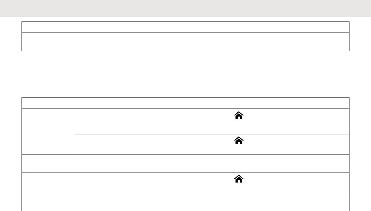
Example Description
Home button
or
Buttons and keys are shown in bold
print or as an icon.
Phon Menu entries are shown similar to
the way they appear on the display
of the radio.
This means “Press the right side of
the 4-Way Navigation Button”.
Additional Performance
Enhancement
The following performance enhancements are some of the
latest creations designed to enhance the security, quality
and efficiency of the radios.
English
Send Feedback 29
Draft

ASTRO 25 Enhanced Data
ASTRO 25 Enhanced Data is optimized to handle different
message sizes and variable update rates from different
applications of the radio. Add Enhanced Data to the
Integrated Data system with a software installation to
improve data channel efficiency and enable denser network
traffic.
Dynamic System Resilience (DSR)
DSR ensures the radio system is seamlessly switched to a
backup master site dynamically in case of system failure.
DSR also provides additional indication e.g. failure
detection, fault recovery, and redundancy within the system
to address to the user in need. Mechanisms related to the
Integrated Voice and Data (IV&D) or data centric are all
supported by DSR.
CrossTalk Prevention
This feature prevents crosstalk scenarios from happening,
especially when a wideband antenna is used. This feature
allows the adjustment of the internal SSI clock rate of the
radio. This subsequently reduces the possibility of radio
frequency interfering spurs and prevents the issues of
crosstalk.
Encrypted Integrated Data (EID)
EID provides security encryption and authentication of
IV&D data bearer service communication between the radio
and the Customer Enterprise Network.
SecureNet
SecureNet allows user to perform secured communications
on an Analog or Motorola Data Communication (MDC)
channel.
Conventional Talkgroup and Radio
Scan Enhancements
A few enhancements have been made to the Conventional
Talkgroup at the system. These enhancements improve the
Scan feature operation significantly when multiple agencies
are using a single conventional radio frequency channel.
These enhancements allow users to use Selective Squelch
to operate on only the subset of talkgroups that are
relevant to the users rather than all talkgroups on the
channel. These Scan improvements have been made to
eliminate the audio holes that were present and to turn on
the busy LED when activity is present on the channel.
Mixed Vote Scan and Standard Conventional Scan
English
30 Send Feedback
Draft

configurations are supported. Priority Operation is also
supported.
Up to 30 different talkgroups can be supported using
conventional channels. A maximum of four talkgroups can
be supported when Vote Scan channels are being used.
Smart PTT is supported with this enhancement as Smart
PTT prevents users from transmitting while other users are
on the channel.
NOTE:
User Selectable Talkgroups are not compatible with
this Conventional Talkgroup Enhancement.
What Your Dealer/System
Administrator Can Tell You
Check with your dealer or system administrator for the
correct radio settings, if the radio is to be operated in
extreme temperatures (less than -30 °C or more than +60
°C).
You can consult your dealer or system administrator about
the following:
• Is your radio programmed with any preset conventional
channels?
• Which buttons have been programmed to access other
features?
• What optional accessories may suit your needs?
NOTE:
Specifications may vary for different radio models.
Check with your dealer or system administrator for
more information.
English
Send Feedback 31
Draft

English
This page intentionally left blank.
32
Draft

Preparing Your Radio for
Use
This section provides simple instructions to prepare your
radio for use.
Charging the Battery
WARNING:
To avoid a possible explosion:
• Do not replace the battery in any area labeled
hazardous atmosphere.
• Do not discard batteries in a fire.
The Motorola-approved battery shipped with your radio is
uncharged. Prior to using a new battery, charge it for a
minimum of 16 hours to ensure optimum capacity and
performance. For a list of Motorola-authorized batteries and
chargers available for use with your radio, see Accessories
on page 205.
NOTE:
When charging a battery attached to a radio, turn
the radio off to ensure a full charge.
To charge the battery, place the battery (with or
without the radio) in a Motorola-approved charger.
The LED on the charger indicates the charging
progress; see the charger user guide.
Attaching the Battery
You can view the status of the IMPRES ™ battery if the
radio is using an IMPRES battery. See IMPRES Battery
Annunciator on page 195 for more information.
1Slide the battery into the radio frame until the latch
which is at the bottom of the radio clicks into place.
English
Send Feedback 33
Draft
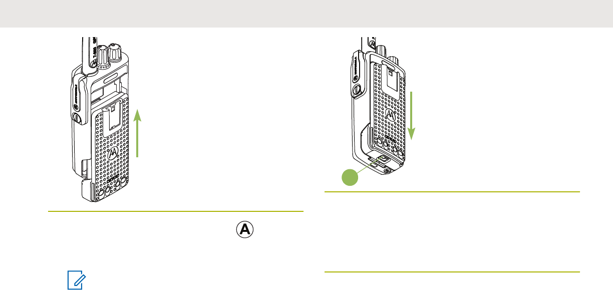
2To remove the battery, lift up the latch which is
at the bottom of the radio, then slide the battery out
from the radio.
NOTE:
When removing the battery, ensure that the
radio is turned off.
A
Attaching the Antenna
Ensure the radio is turned off before attaching the antenna.
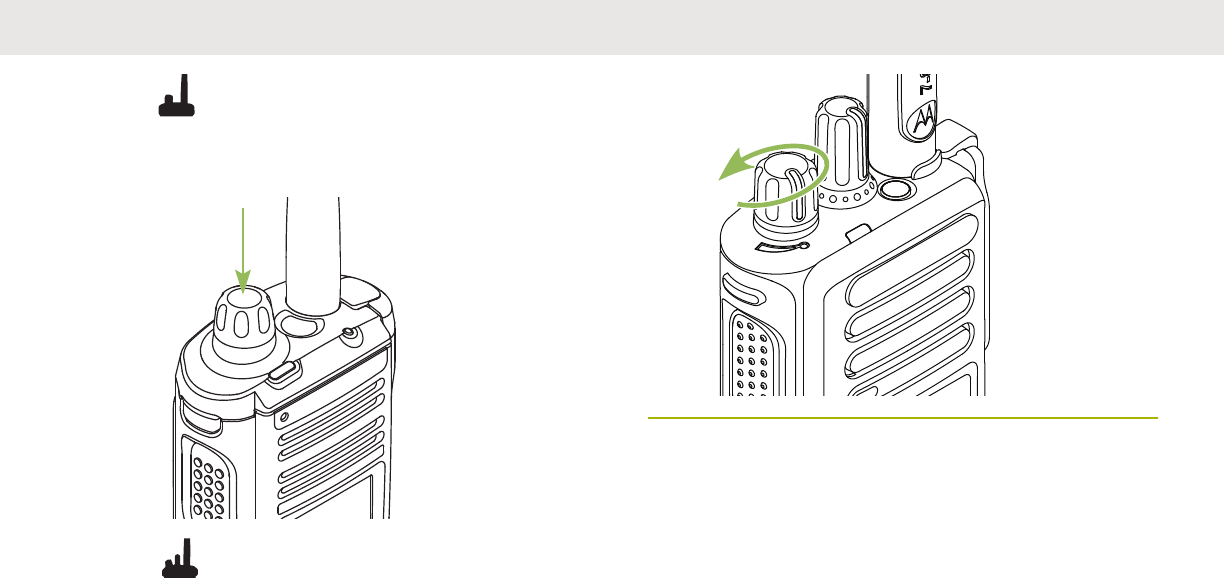
1Set the antenna in its receptacle.
2Turn the antenna clockwise to attach to the radio.
English
34 Send Feedback
Draft
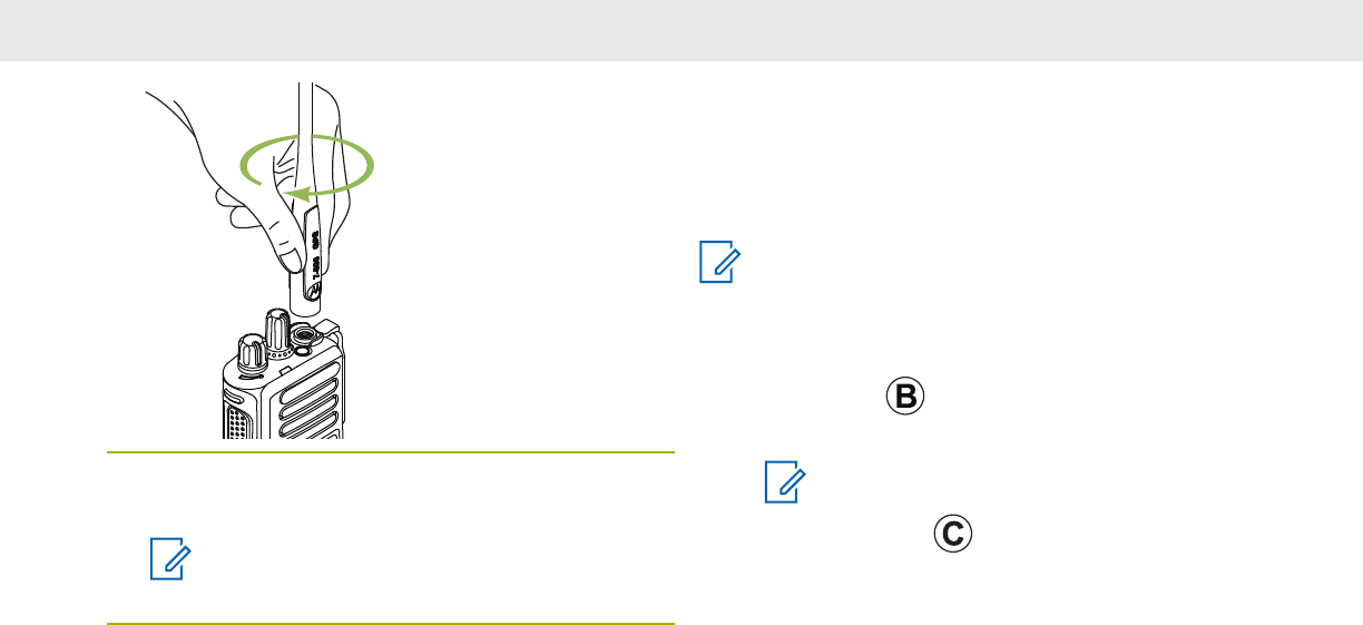
3To remove the antenna, turn the antenna
counterclockwise.
NOTE:
When removing the antenna, ensure that the
radio is turned off.
Removing and Attaching the
Accessory Connector Cover
The accessory connector is on the antenna side of the
radio. It is used to connect accessories to the radio.
NOTE:
To prevent damage to the connector, shield it with
the connector cover when not in use.
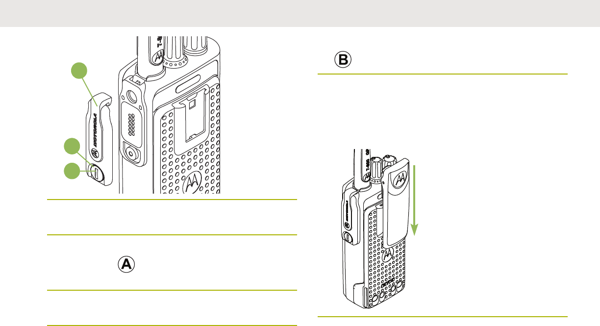
1To remove the accessory connector cover, rotate the
thumbscrew counterclockwise until it
disengages from the radio.
NOTE:
If the thumbscrew is too tight, use an Allen
wrench at to loosen it first.
English
Send Feedback 35
Draft
A
B
C
2Rotate and lift the connector cover to disengage it
from the radio.
3To attach the accessory connector cover, insert the
hooked end of the cover into the slot above the
connector.
4Press downward on the cover’s top to seat it in the
slot.
5Once in place, tighten by rotating the thumbscrew
clockwise by hand.
Attaching the Belt Clip
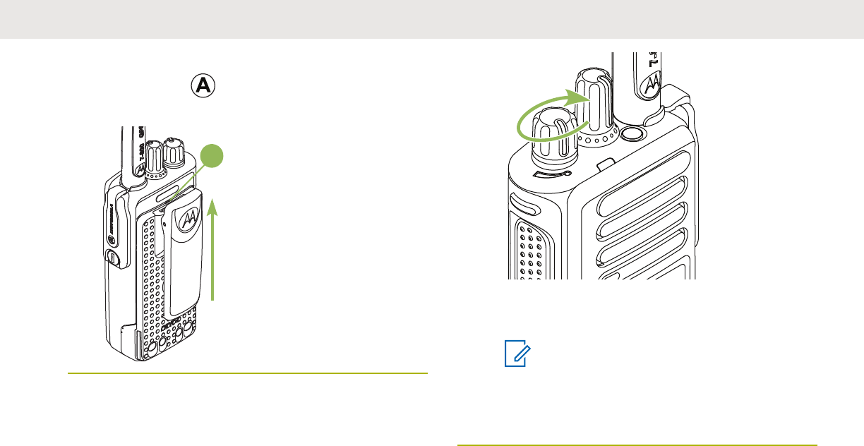
1Align the grooves of the belt clip with those of the
radio and push down until you hear a click.
English
36 Send Feedback
Draft
2To remove the clip, use a flatbladed object to press
the belt clip tab away from the radio. Then, slide
the clip upward and away from the radio.
A
Turning On the Radio
1• Rotate the On/Off/Volume Control Knob
clockwise until you hear a click.
• If the power-up test is unsuccessful, you see
Error XX/YY (XX/YY is an alphanumeric code).
NOTE:
If the radio fails to power-up after
repeating a few times, record the Error
XX/YY code and contact your dealer.
2
English
Send Feedback 37
Draft
• To turn off the radio, press and hold the
Multi-Function Knob until the radio display
shows Power off?, press the Menu Select
button below Yes to power off.
• To turn off the radio, rotate the On/Off/
Volume Control Knob counterclockwise until
you hear a click.
Adjusting the Volume
Ensure the radio is power on and the main speaker is
pointed towards you for increased loudness and
intelligibility, especially in areas with loud background
noises.
English
38 Send Feedback
Draft
Your radio is preprogrammed to reset to medium volume
rate, which is Level 12, by default whenever the radio
powers up.
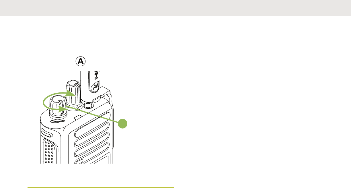
1To increase the volume, rotate the On/Off/Volume
Control Knob clockwise.
A
2To decrease the volume, rotate this knob
counterclockwise.
The display shows volume bars and volume level when you
change the volume.
English
Send Feedback 39
Draft

English
This page intentionally left blank.
40
Draft
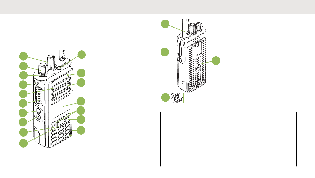

7 Side Button 11
8 Side Button 21
9 Home Button
10 4-Way Navigation Button
11 Keypad
12 Data Feature Button
13 Menu Select Buttons
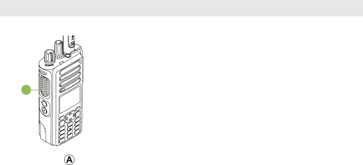
14 Main Display
15 Speaker
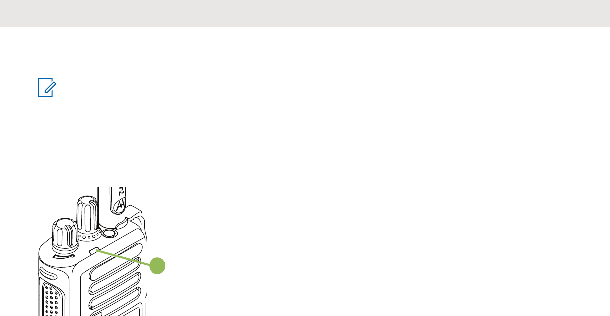
16 Bluetooth Pairing Location Indicator
17 Top (Orange) Button1
18 Antenna
19 Accessory Connector
20 Battery Latch
21 Battery
Programmable Features
Any reference in this manual to controls that are
preprogrammed means that a qualified radio technician
must use the radio programming software to assign a
feature to a control.
Your dealer can program the programmable buttons as
shortcuts to radio functions or preset channels/groups
depending on the duration of a button press:
Press
Pressing and releasing rapidly.
Long press
Pressing and holding for the preprogrammed duration
(between 0.25 seconds and 3.75 seconds).
Hold down
Keeping the button pressed.
Assignable Radio Functions
Bluetooth On/Off
Allows you to turn on/off the Bluetooth.
Bluetooth Configuration
Allows you to access to the Bluetooth menu.
English
42 Send Feedback
Draft

Bluetooth Audio Reroute
Allows you to toggle the audio route between radio
speaker or Remote Speaker Microphone and Bluetooth
headset.
Bluetooth Headset PTT
Keys up the Bluetooth Headset microphone.
Bluetooth Data Devices
Pairs with the data devices for data transfer.
Bluetooth Clear All Pairing
Allows you to clear all pairing information for Bluetooth.
This is accessed by a long press of the Bluetooth
On/Off Button.
Bluetooth Inquiry On/Off
Enables Bluetooth Search feature.
Bluetooth Discoverable On/Off
Enables Bluetooth visibility. This is accessed by a long
press of the Bluetooth Inquiry On/Off Button.
Call Alert
Allows the radio to function like a pager, or to verify if a
radio is active on the system.
Call Response
Allows you to answer a private call.
Channel
Selects a channel.
Contacts
Selects the Contacts menu.
Dynamic ID (Conventional Only)
Allows you to edit the ASTRO Individual ID and/or MDC
Primary ID of the radio.
Dynamic Priority (Conventional Only)
Allows any channel in a Scan List (except for the
Priority-One channel) to temporarily replace the Priority-
Two channel.
Emergency
Depending on the programming, initiates or cancels an
emergency alarm or call.
Information
Displays the information of the radio.
Internet Protocol Address
Display the Internet Protocol (IP) address, device name
and status of the radio.
Location
Determines the current location (latitude, longitude, time
and date), and also the distance and bearing to another
location. Or, turns the GPS functionality on or off for all
locations.
English
Send Feedback 43
Draft

Man Down Clear
Clears the alarm of Man Down mode which was
triggered when your radio achieves or passes a tilt
angle threshold or a combination of the angle threshold
and a motion sensitivity level.
Message
Enters the current message list.
Mode Select
Long-press programs a button with the current zone
and channel of the radio; once programmed, the short-
press of that button changes the radio zone channel to
the programmed zone and channel.
Monitor (Conventional Only)
Monitors a selected channel for all radio traffic until
function is disabled.
Multiple Private Line (Conventional Only)
Selects the Multiple Private Line lists.
Nuisance Delete
Temporarily removes an unwanted channel, except for
priority channels or the designated transmit channel
from the scan list.
One Touch 1– 4
Launches a specific feature with one single button-
press. You can setup as many as four separately
programmed buttons for four different features.
Phone
Allows you to make and receive calls similar to standard
phone calls.
Private Call (Trunking Only)
Allows a call from an individual radio to another
individual radio.
Private Line Defeat (Conventional Only)
Overrides any coded squelch (DPL or PL) that is
preprogrammed to a channel.
Query
Launches a list of predefined short text messages only
after successfully logged in the two-Factor
Authentification.
Radio Profiles
Allows easy access to a set of preprogrammed visual
and audio settings of the radio.
Recent Calls
Allows easy access to the list of calls recently received
or made.
English
44 Send Feedback
Draft

Rekey Request
Notifies the dispatcher you want a new encryption key.
Repeater Access Button (RAB) (Conventional Only)
Allows user to manually send a repeater access
codeword.
Reprogram Request (Trunking Only)
Notifies the dispatcher you want a new dynamic
regrouping assignment.
Request-To-Talk (Conventional Only)
Notifies the dispatcher you want to send a voice call.
Scan
Toggles scan on or off.
Scan List Programming
Selects the scan list for editing (by long press on the
Scan button).
Secure Transmission Select (Conventional and
Trunking)
Toggles the Secure Transmission On or Off when the
Secure/Clear Strapping fields is set to Select for the
current channel and when the radio is model/option
capable.
Selective Call (Conventional Only)
Calls an assigned radio.
Site Display/Search (Trunking Only)
Displays the current site ID and RSSI value; performs
site search for Automatic Multiple Site Select (AMSS) or
SmartZone operation.
Site Lock/Unlock (Trunking Only)
Locks onto a specific site.
Status (Astro 25 Trunking Only)
Sends data calls to the dispatcher about a predefined
status.
Talkaround/Direct (Conventional Only)
Toggles between using a repeater and communicating
directly with another radio.
Talkgroup (Conventional Only)
Allows a call from an individual radio to a group of
radios.
Text Messaging Service (TMS)
Selects the text messaging menu.
TMS Quick Text
Selects a predefined message.
User
Automatically registers with the server.
Zone Select
Allows selection from a list of zones.
English
Send Feedback 45
Draft
Assignable Settings or Utility
Functions
Keypad/Controls Lock
Locks or unlocks the keypad, programmable buttons,
switches or rotary knobs.
Light/Flip
Press the button to toggle the display backlight on or
off; press and hold the button to reverse the content of
the top display.
Voice Announcement
Audibly indicates the current feature mode, Zone or
Channel the user has just assigned.
Voice Mute
Toggles voice mute on or off.
Volume Set Tone
Sets the volume set tone.
Accessing the Preprogrammed
Functions
You can access various radio functions through one of the
following methods.
• A short or long press of the relevant programmable
buttons.
• Use the Menu Select Button.
• Use the Menu Select and Navigation buttons.
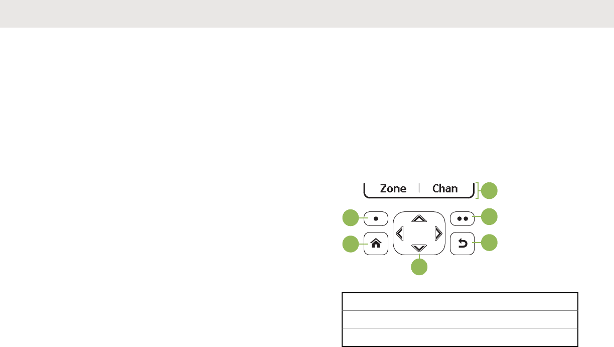
B
C
D
B
E
A
A Softkeys
B Menu Select Buttons
C Back Button
Table continued…
English
46 Send Feedback
Draft
D 4–Way Navigation Button
E Home Button
Menu Select Buttons
NOTE:
Check with your dealer or system administrator for
the list of features activated in your radio.
Use the Menu Select button to access the menu entry of
your radio feature. Your radio may be preprogrammed
differently from the following example, but the steps for
selecting a channel may appear as shown below:
Press the Menu Select button directly below Chan.
Home Button
Pressing the button returns you to the Home (default)
screen. In most cases, this is the current mode. For
selected radio features, the button is also used to save
user-edited radio settings or information before returning
you to the Home screen.
NOTE:
Some features do not require you to press to go
to the Home screen. Refer to the individual feature
sections in this manual for further details on saving
user-edited radio settings or information.
4-Way Navigation Button
Use the 4-Way Navigation Button to scroll up, down, left
or right with one of the following methods.
• Press and release one of the button to scroll from one
entry to the next one.
• Press and hold one of the button to have the radio
toggles through the list automatically (release the button
to stop).
Data Feature Button
Use Data Feature button to access data-related features,
such as the Text Messaging Service (TMS) feature screen.
Keypad
You can use the 3 x 4 alphanumeric keypad to access your
radio features. The keypad functions in a manner similar to
English
Send Feedback 47
Draft
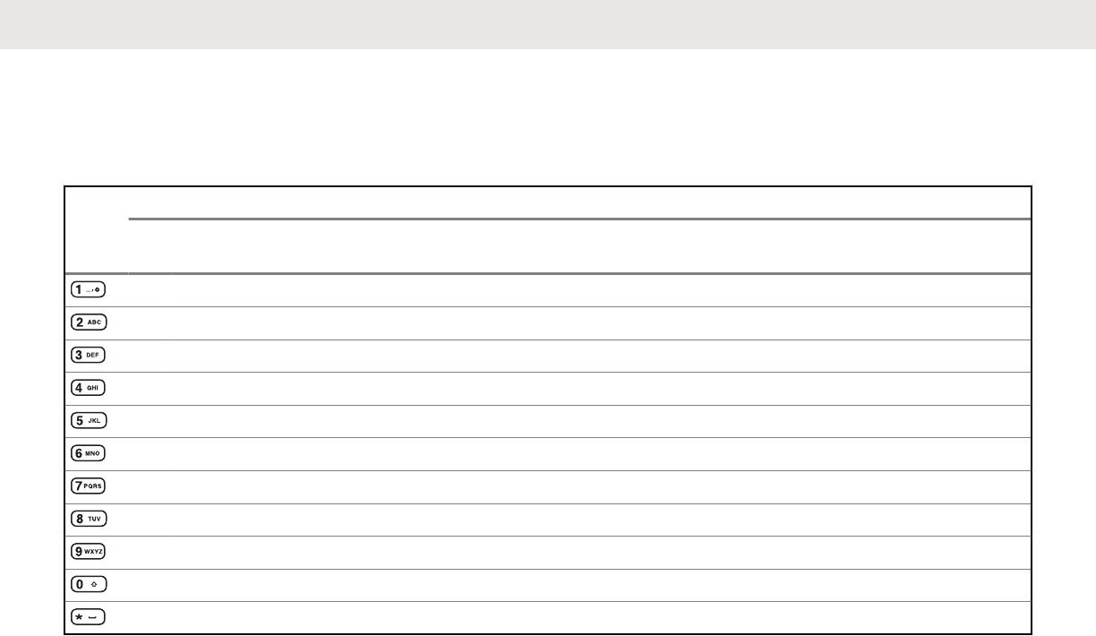
a standard telephone keypad when entering numeric digits.
When the keypad is used to edit a list, each key can
generate different characters of the alphabet. The following
tables show the number of times a key needs to be
pressed to generate the required character.
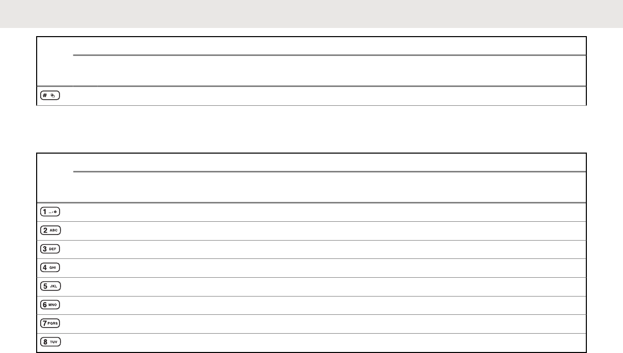
Keypad Characters – Uppercase Mode
Key Number of Times Key is Pressed
1 2 3 4 5 6 7 8 9 1
01
11
21
31
41
51
61
71
81
92
02
1
1 . , ? ! ; @ _ - * # & $ / + = \ “ ‘ ( )
A B C
D E F
G H I
J K L
M N O
P Q R S
T U V
W X Y Z
Toggle between mixed case mode, uppercase mode and lowercase mode.
Space
Table continued…
English
48 Send Feedback
Draft
Key Number of Times Key is Pressed
1 2 3 4 5 6 7 8 9 1
01
11
21
31
41
51
61
71
81
92
02
1
Toggle between numeric and letter mode.
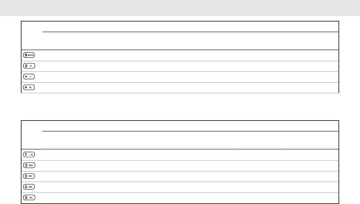
Keypad Characters – Lowercase Mode
Key Number of Times Key is Pressed
1234567891
01
11
21
31
41
51
61
71
81
92
02
1
1 . , ? ! ; @ _ - * # & $ / + = \ “ ‘ ( )
abc
def
ghi
j k l
m n o
p q r s
t u v
Table continued…
English
Send Feedback 49
Draft
Key Number of Times Key is Pressed
1234567891
01
11
21
31
41
51
61
71
81
92
02
1
w x y z
Toggle between mixed case mode, uppercase mode and lowercase mode.
Space
Toggle between numeric and letter mode.
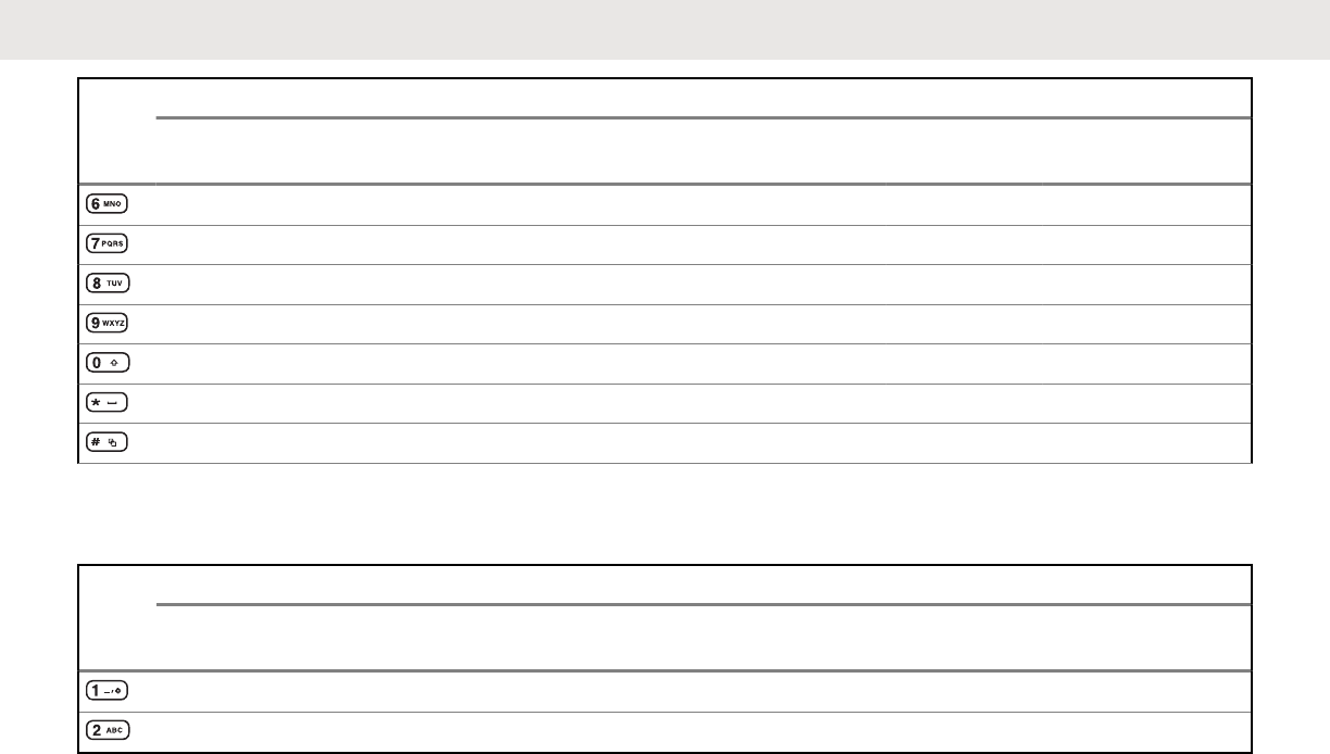
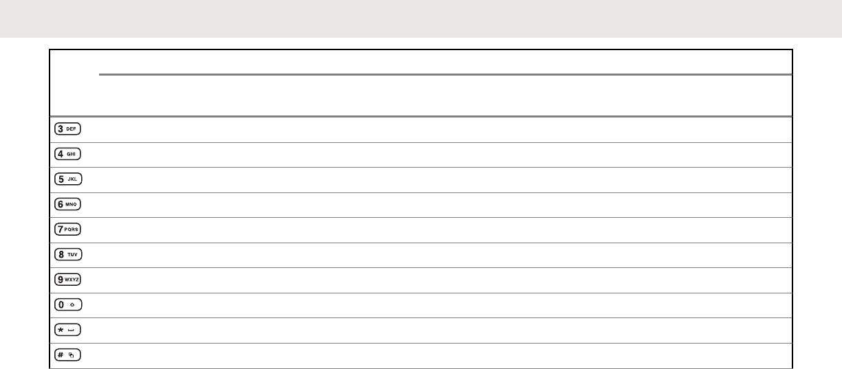
Keypad Characters – Numeric Mode
Key Number of Times Key is Pressed
1 2 3 4 5 6 7 8 9 1
01
11
21
31
41
51
61
71
81
92
02
1
1 . , ? ! ; @ _ - * # & $ / + = \ “ ‘ ( )
2
3
4
5
Table continued…
English
50 Send Feedback
Draft
Push-To-Talk (PTT) Button
A
The PTT button on the side of the radio serves two
basic purposes:
• While a call is in progress, the PTT button allows the
radio to transmit to other radios in the call.
Press and hold down PTT button to talk. Release the
PTT button to listen. The microphone is activated when
the PTT button is pressed.
• While a call is not in progress, the PTT button is used to
make a new call. See Methods to Make a Radio Call on
page 74 for more information.
English
Send Feedback 53
Draft

English
This page intentionally left blank.
54
Draft
Identifying Status Indicators
Status Icons
The 160 x 90 pixel front liquid crystal display (LCD) of your
radio shows radio status, text entries, and menu entries.
The top two display rows contain color icons that indicate
radio operating conditions.
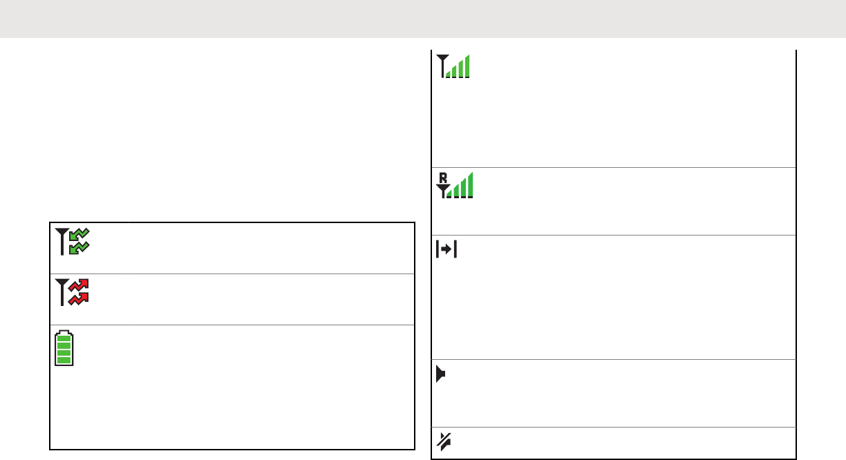
Receiving
Radio is receiving a call or data.
Transmitting
Radio is transmitting a call or data.
Battery
For IMPRES ™ battery operation only – the
icon shown indicates the charge remaining
in the battery.
For all battery operation – the icon blinks
when the battery is low.
Table continued…
Received Signal Strength Indicator
(RSSI)
The number of bars displayed represents
the received signal strength for the current
site, for trunking only. The more stripes in
the icon, the stronger the signal.
Roaming
The radio has roamed to and is currently
registered to a foreign system.
Direct
On – Radio is currently configured for di-
rect radio-to-radio communication (during
conventional operation only).
Off – Radio is connected with other radios
through a repeater.
Monitor (Carrier Squelch)
Selected channel is being monitored (dur-
ing conventional operation only).
In-Call User Alert
Table continued…
English
Send Feedback 55
Draft
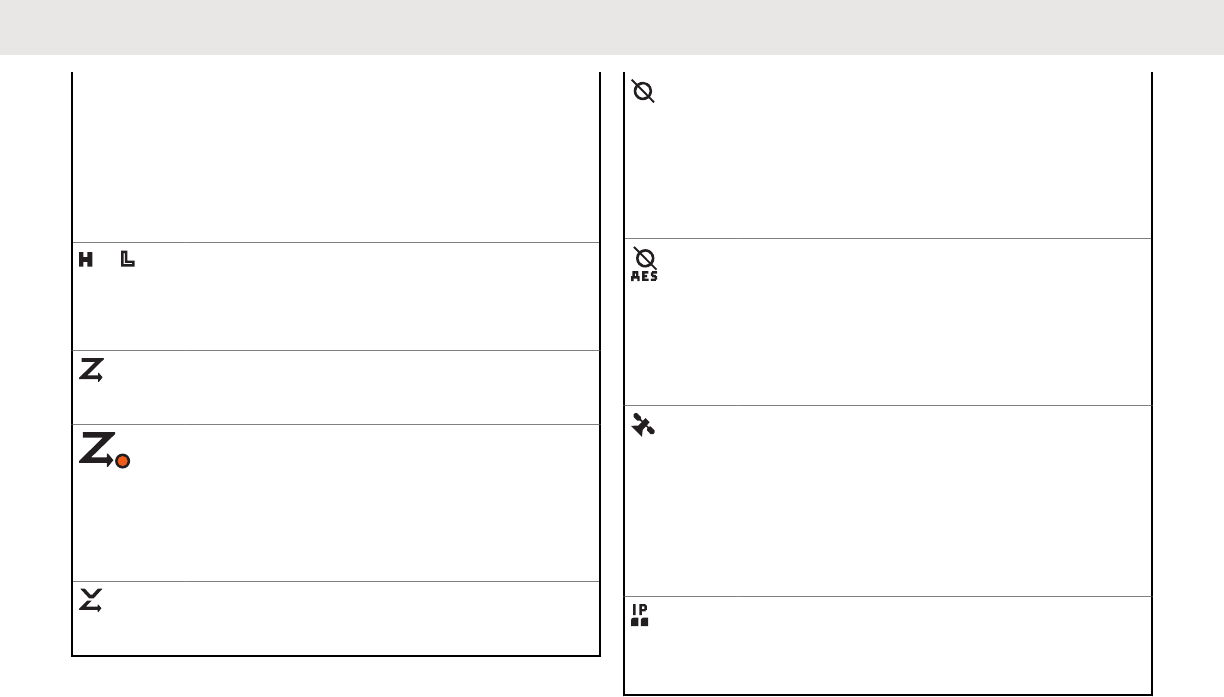
On – The feature is enabled. Voice muting
of the affiliated trunking talkgroup or selec-
ted conventional channel is activated.
Off – The feature is disabled. Voice muting
of the affiliated trunking talkgroup or selec-
ted conventional channel is deactivated.
or Power Level
L – Radio is set at Low power.
H – Radio is set at High power.
Scan
Radio is scanning a scan list.
Priority Channel Scan
Blinking dot – Radio detects activity on
channel designated as Priority-One.
Steady dot – Radio detects activity on
channel designated as Priority-Two.
Vote Scan Enabled
The vote scan feature is enabled.
Table continued…
Secure Operation
On – Secure operation.
Off – Clear operation.
Blinking – Receiving an encrypted voice
call.
AES Secure Operation
On – AES secure operation.
Off – Clear operation.
Blinking – Receiving an encrypted voice
call.
GPS Signal
On – Feature is enabled and signal is
available.
Off – Feature is disabled.
Blinking – Feature is enabled, but no sig-
nal is available.
User Login Indicator (IP Packet Data)
On – User is currently associated with the
radio.
Table continued…
English
56 Send Feedback
Draft
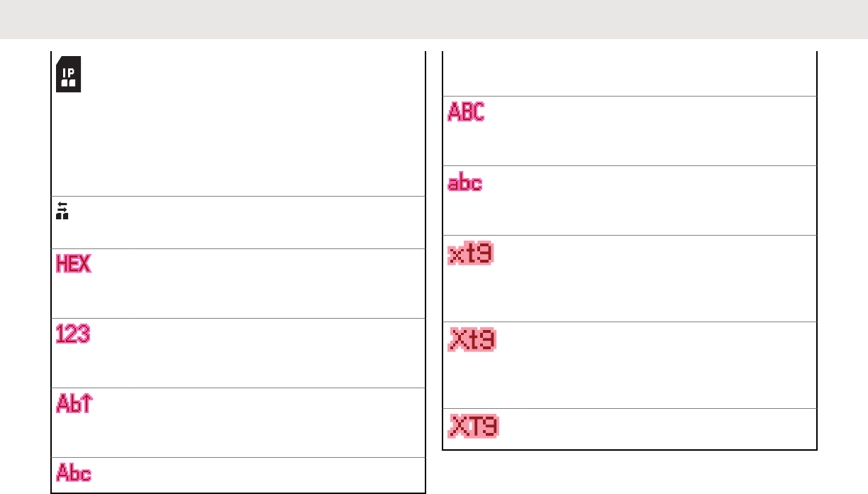
Off – User is currently not associated with
the radio.
Blinking – Device registration or user reg-
istration with the server failed due to an in-
valid username or pin.
Inverted – User successfully login to the
secured IP Packet Data.
Data Activity
Data activity is present.
Hexadecimal
Indicates that the text entry is currently in
hexadecimal mode.
Numeric
Indicates that the text entry is currently in
numeric mode.
Start Case
Indicates that the first character of the text
entry is capitalized.
Mixed Case
Table continued…
Indicates that the text entry is currently in
normal text mode.
Uppercase
Indicates that the text entry is currently in
uppercase mode.
Lowercase
Indicates that the text entry is currently in
lowercase mode.
Lowercase Predictive
Indicates that the text entry is currently in
lowercase and with predicted words shown
at the bottom of the screen.
Mixedcase Predictive
Indicates that the text entry is currently in
mixed case and with predicted words
shown at the bottom of the screen.
Uppercase Predictive
Table continued…
English
Send Feedback 57
Draft
Indicates that the text entry is currently in
uppercase and with predicted words
shown at the bottom of the screen.
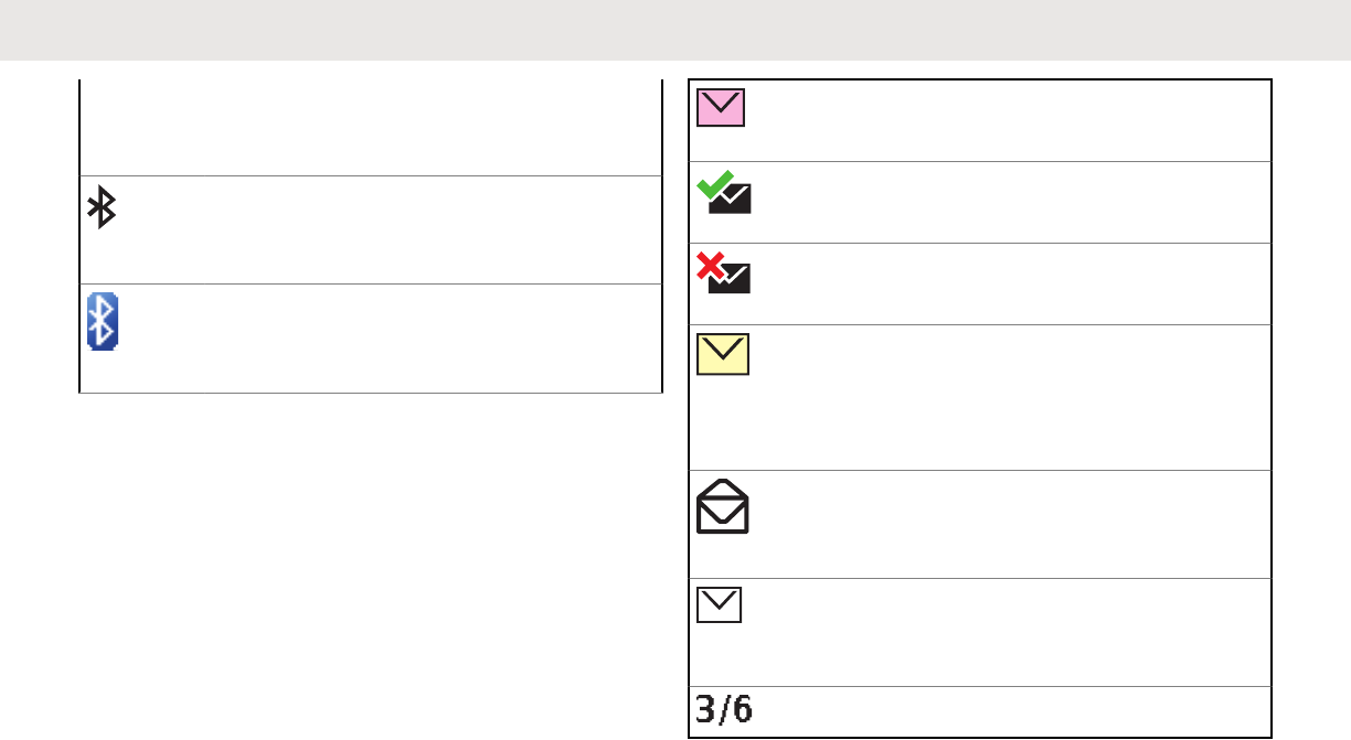
Bluetooth On
Bluetooth is on and ready for Bluetooth
connection.
Bluetooth Connected
Bluetooth is currently connected to the ex-
ternal Bluetooth device.
Text Messaging Service (TMS)
Indicators
This feature allows you to send and receive text messages.
Status icons and menu options shown here help you to
work more efficiently with TMS feature. See Text
Messaging Service (TMS) on page 116 for more
information.
TMS Status Icons
The following icons appear on the radio’s display when you
send and receive text messages.
Inbox Full
The Inbox is full.
Message Sent
The text message is sent successfully.
Message Unsent
The text message cannot be sent.
Unread Message
• User receives a new message.
• The selected text message in the Inbox
has not been read.
Read Message
The selected text message in the Inbox has
been read.
Normal Message
User is composing a message with normal
priority and without a request for a reply.
Message Index
Table continued…
English
58 Send Feedback
Draft
Indicates the index of the current message
the user is viewing.
Example: If the user is looking at the third
message out of a total of 6 messages in the
Inbox folder, the icon is displayed as the icon
on the left column.
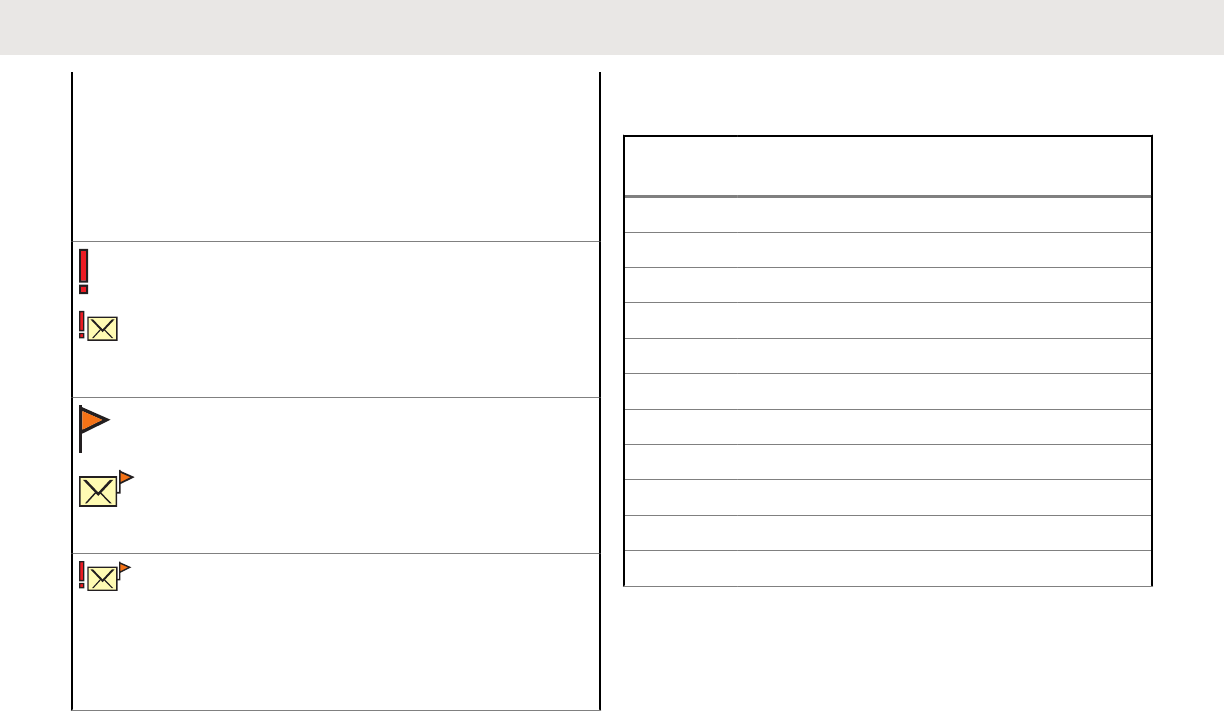
Priority Status
• The “Priority” feature is toggled on before
the message is sent.
• Messages in the Inbox folder are flagged
with “Priority”.
Request Reply
• The “Request Reply” feature is toggled on
before the message is sent.
• Messages in the Inbox folder are flagged
with “Request Reply”.
Priority Status and Request Reply
• User is composing a message with a pri-
ority status and a request for a reply.
• Messages in the Inbox folder are flagged
with “Priority” and “Request Reply”.
TMS Menu Options
Menu
Option Description/Function
Back Brings you back to the previous screen.
Clr Deletes all messages.
Del Deletes a message or text.
Edit Brings you to the edit screen.
Exit Exits to the Home screen.
No Returns to the previous screen.
Optn Brings you to the Options main screen.
Rply Replies to a message.
Sel Selects the highlighted command.
Send Sends the message.
Yes Updates or saves a command.
Call Type Icons
The following icons appear on the radio’s main display,
when you make or receive a call, or view selected call lists,
English
Send Feedback 59
Draft
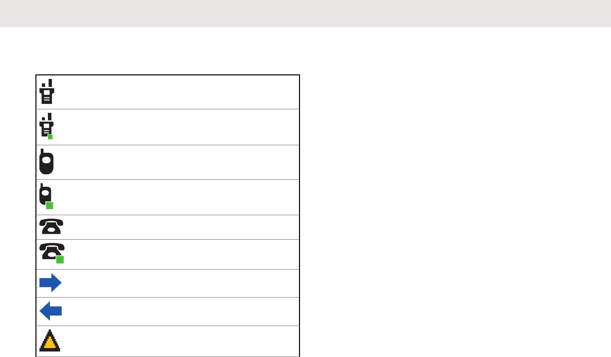
to indicate the different call types associated with an alias
or ID.
Radio number.
Radio number added to a Call List.
Mobile number.
Mobile number added to a Call List.
Landline phone number.
Landline phone number added to a Call
List.
Incoming call or data.
Outgoing call or data.
Incoming emergency call.
LED Indicator
Solid red
Radio is transmitting.
Blinking red
Radio is transmitting at low battery condition.
Double blinking red
Radio is in Emergency Mode.
Rapidly blinking red
Radio has failed the self test upon powering up or
encountered a fatal error.
Solid yellow (Conventional Only)
Channel is busy.
Blinking yellow
Radio is receiving a secured transmission.
Solid green
Radio is powering up, or is on a non-priority channel
while in the Scan List Programming mode.
Blinking green
Radio is receiving an individual or telephone call, or is
on a Priority-Two channel while in the Scan List
Programming mode.
English
60 Send Feedback
Draft
Rapidly blinking green
Radio is on a Priority-One channel while in the Scan List
Programming mode.
NOTE:
No LED indication when the radio receives a clear
(non-secured) transmission in trunking Mode. LED
indication can be preprogramed by qualified
technician to be permanently disabled. Consult your
dealer for further details if you want to disable it.
Top Lightbar Indicator
A
The lightbar turn into solid color of orange, red or green
depending on the status of Intelligent Lighting. See
Intelligent Lighting Indicators on page 62 for different
status of Intelligent Lighting.
English
Send Feedback 61
Draft
Intelligent Lighting Indicators
This feature temporarily changes the color of the Top Lightbar and adds a color bar to the main display screen to help
signal that a radio event has occurred.
NOTE:
This feature must be preprogrammed by a qualified radio technician.
Backlight and Bar
Color Notification When
Orange Emergency Alerts The radio initiates an emergency alarm or call.
The radio receives an emergency alarm or call.
The radio initiates the Man Down Post-Alert timer.
The radio initiates Fireground Evacuation alarm.
Red Critical Alerts The radio battery is low.
The radio is out of range.
The radio enters Failsoft mode.
The radio is unable to establish a full connection with the system.
The radio is unable to authenticate or register with the system.
The radio lost GPS signal or GPS function fails.
Table continued…
English
62 Send Feedback
Draft
Backlight and Bar
Color Notification When
Green Call Alerts The radio receives a private call.
The radio receives a phone call.
The radio receives a call alert.
The radio receives a selective call.
The radio enters Geofence.
Alert Tones
Your radio uses alert tones to inform you of the condition of your radio. The following table lists these tones and when
they occur.
You Hear Tone Name Heard
Short, Low-
Pitched Tone Radio Self Test Fail When radio fails its power-up self test.
Reject When an unauthorized request is made.
Time-Out Timer Warning Four seconds before time out.
No ACK Received When radio fails to receive an acknowledgment.
Table continued…
English
Send Feedback 63
Draft
You Hear Tone Name Heard
Individual Call Warning
Tone When radio is in an individual call for greater than 6 seconds with-
out any activity.
Man Down Entry When radio initiates Man Down mode.
Long, Low-
Pitched Tone Time-Out Timer Timed Out After time out.
Talk Prohibit/PTT Inhibit (When PTT button is pressed) transmissions are not allowed.
Lack of Voice PTT Time
out When the radio ends your call after it detected there is lack of
voice for 60 seconds after the PTT is pressed and hold. Your ra-
dio ends the call to enable your radio to receive calls from other
radio users. The duration of this timer can be preprogrammed by
a qualified radio technician.
Out of Range (When PTT button is pressed) the radio is out of range of the sys-
tem.
Invalid Mode When radio is on an unpreprogrammed channel.
A Group of
Low-Pitched
Tones
Busy When system is busy.
Short, Medi-
um-Pitched
Tone
Valid Key-Press When a correct key is pressed.
Radio Self Test Pass When radio passes its power-up self test.
Clear Voice At beginning of a non-coded communication.
Table continued…
English
64 Send Feedback
Draft

You Hear Tone Name Heard
Priority Channel Received When activity on a priority channel is received.
Emergency Alarm /Call En-
try When entering the emergency state.
Central Echo When central controller has received a request from a radio.
Long, Medi-
um-Pitched
Tone
Volume Set When volume is changed on a quiet channel.
Emergency Exit When exiting the emergency state.
A Group of
Medium-Pitch-
ed Tones
Failsoft When the trunking system fails.
Automatic Call Back When voice channel is available from previous request.
Keyfail When encryption key has been lost.
Console Acknowledge When status, emergency alarm, or reprogram request ACK is re-
ceived.
Received Individual Call When Call Alert or Private Call is received.
Call Alert Sent When Call Alert is received by the target radio.
Site Trunking When a SmartZone trunking system fails.
Short, High-
Pitched Tone
(Chirp)
Low-Battery Chirp When battery is below preset threshold value.
Table continued…
English
Send Feedback 65
Draft

You Hear Tone Name Heard
Two High-
Pitched Tones GPS Fails When the GPS signal is lost or when GPS fails.
Ringing Fast Ringing When system is searching for target of Private Call.
Enhanced Call Sent When waiting for target of Private Call to answer the call.
Phone Call Received When a land-to-mobile phone call is received.
Gurgle Dynamic Regrouping (When PTT button is pressed) a dynamic ID has been received.
Talk Permit (When PTT button is pressed) is verifying with the system for ac-
cepting its transmissions.
Unique, Low-
Pitched Chirp New Message When a new message is received.
Unique, High-
Pitched Chirp Priority Status When a priority message is received.
Incremental-
Pitched Tone Bluetooth Paired When Bluetooth accessory is paired with the radio.
Bluetooth Connected When Bluetooth accessory is connected to the radio.
Decremental-
Pitched Tone Bluetooth Unpaired When Bluetooth accessory is unpaired from the radio.
Bluetooth Disconnected When Bluetooth accessory is disconnected from the radio.
A Group of
Very High-
Pitched Tones
Man Down Continuous
Tone When radio is in Man Down mode and prepares to transmit Emer-
gency Alarm when the timer of this alarm ends.
Table continued…
English
66 Send Feedback
Draft
You Hear Tone Name Heard
Critical Man Down Contin-
uous Tone When radio is in Man Down Enhanced mode and prepares to
transmit Emergency Alarm when the timer of this alarm ends.
Phone Call Displays and Alerts
The following phone call displays and alerts appears on the radio’s display when you make and receive Phone calls. The
radio also uses alert tones to indicate the current status.
You Hear You See When Notes
A Long Tone No phone You press the PTT button
and the phone system is
not available.
Press to hang up. The radio returns to the
Home screen.
Phone busy The phone system is busy. Press to exit the phone mode and try your
call later.
A Busy Tone Phone busy When a channel is not
available. The radio automatically connects when a
channel opens.
– No acknowl-
edge The call is not acknowl-
edged. Press to hang up. The radio returns to the
Home screen.
A High- Pitch-
ed Tone – When you release the PTT
button. The radio indicates to the landline party that
he or she may begin talking.
English
Send Feedback 67
Draft

NOTE:
You have the option of sending additional digits (overdial), such as an extension number, or credit card or PIN
numbers, to the phone system. If the radio is preprogrammed for live overdial, every digit entered after the call is
connected is sent to the phone system.
If the radio is preprogrammed for buffered overdial, the digits pressed are entered into memory and then sent
when the PTT button is pressed. Press the PTT button to send either digits or voice, but not both at the same time.
HAZLOC Battery Type Detection
This feature alerts the user when there is a HAZLOC
certification mismatch between the radio and the battery.
This feature supports IMPRES batteries only.
During power up, if there is a mismatch, the following
scenarios occurs:
• The radio repetitively displays WRONG BATTERY with red
intelligent backlight
• The Battery icon blinks continuously
• A repetitive tone sounds
• LED blinks RED continuously
NOTE:
The radio does not display any indication when
the radio is connected to the charger, when the
radio and battery match, or when the radio
certification type is configured as "None" in
Customer Programming Software (CPS).
This feature is enabled through CPS configuration. Check
with your dealer or system administrator for more
information.
English
68 Send Feedback
Draft
General Radio Operation
Selecting a Zone
Your radio must be preprogrammed to allow you to use this
feature.
A zone is a group of channels. The following methods are
options on how to select a radio zone. The result of all the
methods is the same. You can use the options
interchangeably depending on your preference and the
programmed functions.
• Select a zone via the radio menu Zone:
a. or to Zone and press the Menu Select
button directly below Zone.
b. or to the required zone, or use the
keypad to enter the zone number.
If the zone number entered is unprogrammed, the
display shows Invalid entry. Repeat this step.
c. Press the Menu Select button directly below Sel
to confirm the displayed zone.
d. Press the PTT button to transmit on the displayed
zone channel.
• Select a zone via the radio menu ZnUp or ZnDn:
a. or to ZnUp or ZnDn.
b. Press and hold the Menu Select button directly
below ZnUp or ZnDn until the required zone
appears.
Positions of ZnUp and ZnDn on the display may
differ each time you release the Menu Select
button. Read carefully before you press.
c. Press the PTT button to transmit on the displayed
zone channel.
Selecting a Radio Channel
A channel is a group of radio characteristics, such as
transmit/ receive frequency pairs. The following methods
are options on how to select a radio channel. The result of
all the methods is the same. You can use the options
interchangeably depending on your preference and the
programmed functions.
• Select a channel via the preprogrammed 16–
Position Select Knob to the desired channel.
English
Send Feedback 69
Draft
a. Rotate the preprogrammed 16–Position Select
Knob to the desired channel.
b. Press the PTT button to transmit on the displayed
zone channel.
• Select a channel via the radio menu Chan:
a. or to Chan.
b. Press the Menu Select button directly below
Chan.
c. or to the required channel or use the
keypad to enter the channel number.
If the channel number entered is unprogrammed,
the display shows Invalid entry. Repeat this
step.
d. Press the Menu Select button directly below Sel
to confirm the selected channel.
e. Press the PTT button to transmit on the displayed
zone channel.
• Select a channel via the radio menu Channel Up or
Channel Down:
a. or to ChUp or ChDn.
b. Press the Menu Select button directly below
ChUp or ChDn.
Positions of ChUp and ChDn on the display may
differ each time you release the Menu Select
button. Read carefully before you press.
c. Press the PTT button to transmit on the displayed
zone and channel.
Selecting a Channel via Channel
Search Button
This feature allows you to do a quick search for a specific
channel in your radio by keying in the alias of the channel.
If the name matches, your radio prompts the first found
matched channel name.
1Perform one of the following actions:
• Press the preprogrammed Channel Search
button.
• or to CSrh and press the Menu Select
button directly below CSrh.
A blinking cursor appears on the Channel Search
screen.
English
70 Send Feedback
Draft
2Use the keypad to type or edit your channel name.
3To initiate searching, press the Menu Select button
directly below CSrh once the entry is done.
To exit this procedure, press the Menu Select button
directly below Cncl.
The display shows Searching. Once found, the display
shows the matched channel name and the radio changed
its transmission to the selected channel.
If the radio is triggered to search for an empty entry, the
display shows Invalid entry. Repeat step step 2 to
search again.
If the entry does not match, the display shows Channel
name not found. Repeat step step 2 to search again; or
press or the Menu Select button directly below Exit to
exit.
Mode Select Feature
Mode Select allows a long press to save the current zone
and channel of your radio to a programmable button,
keypad button, or a softkey; then once programmed, the
short-press of that button or softkey changes the
transmission to the saved zone and channel.
There are two methods to save the selected zone and
channel:
• Softkeys
• Programmable buttons and keypad buttons (digit 0 to 9)
NOTE:
Your radio must be preprogrammed to allow you to
use this feature.
Saving a Zone and a Channel to a
Softkey
Five softkeys are available for you to save the frequently
used zone and channel.
1Toggle your zone and channel to the required zone
and channel.
2 or to MS1, MS2 ... or MS5.
3Press and hold the Menu Select button directly
below one of the softkey (MS1 – MS5).
You hear a short, medium-pitched tone when the zone and
channel is saved.
English
Send Feedback 71
Draft

NOTE:
To change the programmed zone and channel,
repeat this procedure.
Short press of the programmed softkey changes
your current transmission to the zone and channel
programmed in this softkey.
Saving a Zone and a Channel to a
Button
You can save the frequent used zone and channel to the
programmable buttons and keypad digit 0 to 9 buttons.
1Toggle your zone and channel to the required zone
and channel.
2Press and hold the button you desire to program.
You hear a short, medium-pitched tone when the zone and
channel is saved.
NOTE:
Repeat this procedure to change the zone and
channel of the programmed button.
Short press of the programmed button changes your
current transmission to the zone and channel
programmed in this button.
Receiving and Responding to a
Radio Call
Once you have selected the required channel and/or zone,
you can proceed to receive and respond to calls.
The LED lights up solid red while the radio is transmitting.
In conventional mode, the LED lights up solid yellow when
the radio is receiving a transmission. In trunking mode,
there is no LED indication when the radio receives a
transmission.
If the radio is receiving a secure transmission, the LED
blinks yellow.
Receiving and Responding to a
Talkgroup Call
To receive a call from a group of users, your radio must be
configured as part of that talkgroup.
When you receive a talkgroup call (while on the Home
screen) the radio triggers for your attention with one of the
following scenarios depending on the system your radio is
configured:
English
72 Send Feedback
Draft
• For ASTRO Conventional system, the LED lights up
solid yellow. The display shows the talkgroup alias or
ID, and the caller alias or ID.
• For Trunking system, the display shows the caller alias
or ID.
1Hold the radio vertically 1 to 2 in. (2.5 to 5.0 cm)
from your mouth.
2Press the PTT button to respond to the call.
The LED lights up solid red.
3Release the PTT button to listen.
See also Making a Talkgroup Call on page 74 for details
on making a Talkgroup Call.
Receiving and Responding to a Private
Call (Trunking Only)
A Private Call is a call from an individual radio to another
individual radio.
The one-to-one call between the two radios are not heard
by the others in the current talkgroup. The calling radio
automatically verifies that the receiving radio is active on
the system and can display the caller ID.
NOTE:
With the inactivity timer enabled (optional), when
there is no response from the receiving radio, the
calling radio exits the call with Menu Inactive Exit
tone after the timer expires.
When you receive a Private Call, you hear two alert tones
and the LED blinks green. The display shows Call
received and the call received icon blinks.
1Perform one of the following actions:
• Press the Menu Select button directly below
Resp.
• Press the Call Response button within 20
seconds after the call indicators begin.
If the caller alias is in the call list, the display shows
the caller alias during the call.
If the caller name is not in the call list, the display
shows the caller ID.
2Press and hold the PTT button to talk. Release the
PTT button to listen.
English
Send Feedback 73
Draft
3Press or the Call Response button to hang up
and return to the Home screen.
See also Making a Private Call (Trunking Only) on page
75 for details on making a Private Call.
Receiving and Responding to a
Telephone Call (Trunking Only)
This feature allows you to receive calls similar to standard
phone calls from a landline phone.
NOTE:
With the inactivity timer enabled (optional), if there is
no response to the call after the timer expires, your
radio exits the call with Menu Inactive Exit tone.
When you receive a Telephone Call, you hear a telephone-
type ringing and the LED blinks green. The display shows
Phone Call and the call received icon blinks.
1Press the Call Response button within 20 seconds
after the call indicators begin.
2Press and hold the PTT button to talk. Release the
PTT button to listen.
3Press or the Call Response button to hang up
and return to the Home screen.
See also Making a Telephone Call (Trunking Only) on page
77 for details on making a Telephone Call.
Methods to Make a Radio Call
You can select a zone, channel, subscriber ID, or talkgroup
by using:
• The 16-Position Select Channel Knob.
• The Contacts list (see Viewing Details of a Contact on
page 94).
NOTE:
The radio automatically exits the feature, if the
feature inactivity timer is enabled, when the radio is
left idle and the timer expires. You will hear the
Menu Inactive Exit Tone upon feature exit.
Making a Talkgroup Call
To make a call to a group of users, your radio must be
configured as part of that talkgroup.
English
74 Send Feedback
Draft
1Turn the 16-Position Select Channel Knob to
select the channel with the desired talkgroup.
2Hold the radio vertically 1 to 2 in. (2.5 to 5.0 cm)
from your mouth.
3Press the PTT button to make the call.
The radio shows different indicators based on the
system the radio is configured.
• For ASTRO Conventional system, the LED lights
up solid red. The display shows the talkgroup
alias or ID.
• For Trunking system, the LED lights up solid red.
4Speak clearly into the microphone.
5Release the PTT button to listen.
Making a Private Call (Trunking Only)
Your radio must be preprogrammed to allow you to use this
feature.
This feature allows you to send an individual Call Alert or
page if there is no answer from the target radio.
1 or to Call, and press the Menu Select button
directly below Call.
The display shows the last transmitted or received
ID.
2To select the required ID, perform one of the
following actions:
• Press the Menu Select button directly below
Cnts to scroll through and select the required ID.
• Press the Menu Select button directly below
LNum to go to the last number dialed.
• or to the required ID.
• Use the keypad to enter the required ID.
3Press the PTT button to initiate the Private Call.
The display shows Calling... <Number>.
English
Send Feedback 75
Draft
4Hold the radio vertically 1 to 2 in. (2.5 to 5.0 cm)
from your mouth.
When you are connected, the display shows the ID
of the target radio.
If no acknowledgment is received, the display shows
No acknowledge.
5Press and hold the PTT button to talk. Release the
PTT button to listen.
6Press to return to the Home screen.
Making an Enhanced Private Call
(Trunking Only)
Your radio must be preprogrammed to allow you to use this
feature.
This feature allows you to send an individual Call Alert
Page if there is no answer from the target radio. See
Sending a Call Alert Page on page 99 for more
information.
1 or to Call, and press the Menu Select button
directly below Call.
The display shows the last transmitted or received
ID.
2To select the required ID, perform one of the
following actions:
• Press the Menu Select button directly below
Cnts to scroll through and select the required ID.
• Press the Menu Select button directly below
LNum to go to the last number dialed.
• or to the required ID.
• Use the keypad to enter the required ID.
3Press the PTT button to initiate the Private Call.
The display shows Calling... <Number>.
English
76 Send Feedback
Draft
4Hold the radio vertically 1 to 2 in. (2.5 to 5.0 cm)
from your mouth.
When you are connected, the display shows the ID
of the target radio.
If no acknowledgment is received, the display shows
No acknowledge.
If the target radio does not respond before the time
out, the display shows No answer.
5Press and hold the PTT button to talk. Release the
PTT button to listen.
6Press to return to the Home screen.
Making a Telephone Call (Trunking
Only)
This feature allows you to make calls similar to standard
phone calls to a mobile or landline phone.
1 or to Phon, and press the Menu Select button
directly below Phon.
The display shows the last transmitted or received
ID.
2To select the required ID, perform one of the
following actions:
• Press the Menu Select button directly below
Cnts to scroll through and select the required ID.
• Press the Menu Select button directly below
LNum to go to the last number dialed.
• or to the required phone number.
• Use the keypad to enter the required phone
number.
3Press the PTT button to dial the phone number.
English
Send Feedback 77
Draft
4Hold the radio vertically 1 to 2 in. (2.5 to 5.0 cm)
from your mouth.
5When your call is answered, press and hold the PTT
button to talk. Release the PTT button to listen.
6Press to return to the Home screen.
See Phone Call Displays and Alerts on page 67 for more
information if your call is NOT answered.
Switching Between Repeater or
Direct Operation Button
The Repeater Operation increases the radio coverage
area by connecting with other radios through a repeater.
The transmit and receive frequencies are different.
The Direct or “talkaround operation” allows you to bypass
the repeater and connect directly to another radio. The
transmit and receive frequencies are the same.
Perform one of the following actions:
• Press the preprogrammed Repeater/Direct
switch to toggle between talkaround and repeater
modes.
• or to Dir and press the Menu Select button
directly below Dir.
The display shows Repeater mode if the radio is currently
in Repeater mode.
The display shows Direct mode and the Talkaround icon if
the radio is currently in Direct mode (during conventional
operation only).
Monitor Feature
Radio users who switch from analog to digital radios often
assume that the lack of static on a digital channel is an
indication that the radio is not working properly. This is not
the case.
Digital technology quiets the transmission by removing the
noise from the signal and allows only the clear voice or
data information to be heard.
Use the Monitor feature to make sure a channel is clear
before transmitting.
English
78 Send Feedback
Draft

Monitoring a Channel
The following methods are options on how to monitor a
channel. The result of all the methods is the same. You can
use the options interchangeably depending on your
preference and the programmed functions.
• Monitoring a Channel with Monitor button.
a. Press the preprogrammed Monitor button.
b. Adjust the Volume Control Knob if necessary.
c. Press and hold the PTT button to transmit.
The LED lights up solid red.
d. Release the PTT button to receive (listen).
The Carrier Squelch indicator appears on the
display when you monitor a channel via the
preprogrammed Monitor button.
• Monitoring a Channel via the selected zone channel.
a. Select the desired zone and channel.
b. Listen for a transmission.
c. Adjust the Volume Control Knob if necessary.
d. Press and hold the PTT button to transmit.
The LED lights up solid red.
e. Release the PTT button to receive (listen).
Monitoring Conventional Mode
Your radio may be preprogrammed to receive Private-Line®
(PL) calls.
1Momentarily press the Monitor button to listen for
activity.
The Carrier Squelch indicator appears on the
display.
2Press and hold the Monitor button to set continuous
monitor operation.
The duration of the button press is programmable.
3Press the Monitor button again, or the PTT button,
to return to the original squelch setting.
If you try to transmit on a receive-only channel, you
hear an invalid tone until you release the PTT button.
English
Send Feedback 79
Draft

English
This page intentionally left blank.
80
Draft
Advanced Features
Advanced Call Features
Selective Call (ASTRO Conventional
Only)
This feature allows you to receive a call from or to call a
specific individual. It is intended to provide privacy and to
eliminate the annoyance of having to listen to
conversations that are of no interest to you.
Receiving a Selective Call
When you receive a Selective Call, the radio indicates one
of the followings:
• You hear two alert tones and the LED lights up solid
yellow to indicate the transmitting radio is still sending
signal. The call received icons blinks and the display
shows Call received.
• The LED blinks solid green once to indicate the
transmitting radio is pending to receive signal.
The speaker unmutes.
1Hold the radio vertically 1 to 2 in. (2.5 to 5.0 cm)
from your mouth.
2Press and hold the PTT button to talk. Release the
PTT button to listen.
Making a Selective Call
1 or to Call, and press the Menu Select button
directly below Call.
The display shows the last transmitted or received
ID.
2To select the required ID, perform one of the
following actions:
• Press the Menu Select button directly below
Cnts to scroll through and select the required ID.
• Press the Menu Select button directly below
LNum to go to the last number dialed.
• or to the required ID.
English
Send Feedback 81
Draft
• Use the keypad to enter the required ID.
3Hold the radio vertically 1 to 2 in. (2.5 to 5.0 cm)
from your mouth.
4Press and hold the PTT button to start the Selective
Call.
The display shows the ID of the target radio.
5Release the PTT button to listen.
6Press to return to the Home screen.
Talkgroup Call Feature (Conventional
Operation Only)
This feature allows you to define a group of conventional
system users so that they can share the use of a
conventional channel.
NOTE:
Encryption keys are associated to talkgroups. When
talkgroups are associated, encryption keys are
changed by changing the active talkgroup. See
Secure Operations on page 134 for more
information.
Selecting a Talkgroup
1 or to Tgrp and press the Menu Select button
directly below Tgrp.
The display shows the last Talkgroup that was
selected and stored.
2Perform one of the following actions:
• or to Preset for the preset
preprogrammed Talkgroup.
• Use the keypad to enter the number of the
corresponding Talkgroup in the list.
English
82 Send Feedback
Draft
3Press the Menu Select button directly below Sel to
save the currently selected Talkgroup and return to
the Home screen.
If the encryption key associated to the new
Talkgroup is erased, you hear a momentary key fail
tone and the display shows Key fail.
If the encryption key that is associated to the new
Talkgroup is not allowed, you hear a momentary key
fail tone and the display shows Illegal key.
4Press to return to the Home screen.
Sending a Status Call
This feature allows you to send data calls to the dispatcher
about a predefined status.
Each status can have up to a 14-character name. A
maximum of eight status conditions is possible.
NOTE:
The radio automatically exits the feature, if the
feature inactivity timer is enabled, when the radio is
left idle and the timer expires. You will hear the
Menu Inactive Exit Tone upon feature exit.
1Perform one of the following actions:
• Press the preprogrammed Status button.
• or to Sts and press the Menu Select button
directly below Sts.
The display shows the last acknowledged status call,
or the first status in the list.
2Perform one of the following actions:
• Use the keypad to enter a number corresponding
to the location in the status list.
3Press the PTT button to send the status.
When the dispatcher acknowledges, you hear four
tones and the display shows Ack received . The
radio returns to normal dispatch operation.
English
Send Feedback 83
Draft
If no acknowledgment is received, you hear a low-
pitched tone and the display shows No
acknowledge.
4Press to return to the Home screen.
No traffic is heard on trunked channels while Status
Calls is selected. If the radio detects no Status Call
activity for six seconds, an alert tone sounds until
you press or the PTT button.
Responding to the Dynamic
Regrouping Feature (Trunking Only)
This feature allows the dispatcher to temporarily reassign
selected radios to a particular channel where they can
communicate with each other. This feature is typically used
during special operations and is enabled by a qualified
radio technician.
You will not notice whether your radio has this feature
enabled until a dynamic regrouping command is sent by
the dispatcher.
NOTE:
If you try to access a zone or channel that has been
reserved by the dispatcher as a dynamically
regrouped mode for other users, you hear an invalid
tone.
When your radio is dynamically regrouped, it automatically
switches to the dynamically regrouped channel. You hear a
Gurgle tone and the display shows the dynamically
regrouped channel’s name.
Press the PTT button to talk. Release PTT button to
listen.
When the dispatcher cancels dynamic regrouping, the radio
automatically returns to the zone and channel that you
were using before the radio was dynamically regrouped.
Requesting a Reprogram (Trunking Only)
This feature allows you to notify the dispatcher when you
want a new dynamic regrouping assignment.
Perform one of the following actions:
• Press the preprogrammed Reprogram Request
button to send reprogram request to the
dispatcher.
English
84 Send Feedback
Draft

• or to Rpgm then press the Menu Select
button directly below Rpgm to send reprogram
request to the dispatcher.
The display shows Reprgrm rqst and Please
wait.
If you hear five beeps, the dispatcher has acknowledged
the reprogram request. The display shows Ack received
and the radio returns to the Home screen.
If the dispatcher does not acknowledge the reprogram
request within six seconds, you hear a low-pitched alert
tone and the display shows No acknowledge. Try again or
press to cancel and return to the Home screen.
Classification of Regrouped Radios
The dispatcher can classify regrouped radios into either of
two categories:
Select Enabled
Select-enabled radios are free to change to any
available channel, including the dynamic-regrouping
channel, once the user has selected the dynamic-
regrouping position.
Select Disabled
Select-disabled radios cannot change channels while
dynamically regrouped. The dispatcher has forced the
radio to remain on the dynamic-regrouping channel.
The Scan or Private Call feature cannot be selected while
your radio is Select Disabled.
Dynamic Zone Programming (DZP)
NOTE:
Your radio must be preprogrammed to allow you to
use this feature. This feature works on the condition
at least one zone in the radio must be a non-
dynamic zone.
This feature provides one or more Dynamic Zones to store
frequently used channels be it conventional or trunking.
These dynamic channels are saved from pre-existing (non-
dynamic) channels in the radio. This saves the time and
effort from the regular navigation around the working zones
and channels. User can also delete or update the list in the
Dynamic Zone.
English
Send Feedback 85
Draft
Entering the Dynamic Zone to Select a
Dynamic Channel
1 or to Zone then press the Menu Select button
directly below Zone.
The display shows the Zone screen.
2 or to <# Dynamic Zone Channels>2
3Perform one of the following actions:
• Press the Menu Select button below Sel to
select.
• Press the Menu Select button below Exit to exit.
If you have selected one of the Dynamic Zone
Channels list, the display returns to Home screen
with the selected <# Dynamic Zone Channels>
shown on the screen.2
If you have selected Exit without selecting any
Dynamic Zone Channels list, the display returns to
Home screen without any changes.
2
Saving a Channel in the Dynamic Zone
from List Selection
The radio must be in Dynamic Zone in order to perform this
operation.
1 or to ZnPr. Press the Menu Select button
directly below ZnPr to enter Program Zone screen.
2Press the Menu Select button directly below Edit.
The display shows Search Options screen.
3 or to List Selection. Press the Menu
Select button directly below Sel.
The display shows Select Zone screen.
2# indicates number of the channel on the 16-Position Switch which are numbered from 1 to 16.
English
86 Send Feedback
Draft
4 or to the required zone. Press the Menu
Select button directly below Sel.
The display shows Select Chan screen.
5 or to the required channel. Press the Menu
Select button directly below Sel.
The display shows Channel updated.
6Press the Menu Select button directly below Exit to
return to Home screen.
Saving a Channel in the Dynamic Zone
from Channel Name
The radio must be in Dynamic Zone in order to perform this
operation.
1 or to ZnPr then press the Menu Select button
directly below ZnPr to enter Program Zone screen.
2Press the Menu Select button directly below Edit.
The display shows Search Options screen.
3 or to Channel Name then press the Menu
Select button directly below Sel.
The display shows a blinking cursor on the Channel
Name screen.
4Use the keypad to type or edit the channel name.
5Press the Menu Select button directly below Srch
once the entry is done to initiate searching.
You can cancel this operation at this step by
pressing the Menu Select button directly below Cncl
to return to Search Options screen.
The display shows Searching.... Once found, the
display shows Channel updated.
If the radio is triggered to search for an empty entry,
the display shows Invalid entry.
If the entry does not match, the display shows
Channel name not found. Repeat from step step 4
or step 5 to search again.
6Press to return to the Home screen.
English
Send Feedback 87
Draft
Deleting a Channel in the Dynamic Zone
The radio must be in Dynamic Zone in order to perform this
operation.
1 or to ZnPr then press the Menu Select button
directly below ZnPr to enter Program Zone screen.
The display shows the dynamic channels list.
2 or to the saved dynamic channel then press
the Menu Select button directly below Del.
The display shows Channel deleted screen.
3Press the Menu Select button below Exit to return
to Home screen.
The Home screen shows <Dynamic Zone
Channels>.
If the channel deleted is the Home channel, the
Home screen shows <Zone Name>+”Blank”.
Contacts
This feature provides “address-book” capabilities on your
radio. Each entry corresponds to an alias (name) or ID
(number) that you use to initiate a call.
Contact entries are alphabetically sorted according to entry
alias. Each alias can have up to five IDs of different call
types associated with it.
Additionally, each entry, depending on context
(conventional, trunking, or phone), associates with one or
more of the four types of calls: Phone Call, Selective Call,
Private Call, or Call Alert.
Each entry within Contacts contains the following
information:
• Call Alias (Name)
• Call ID (Number)
• Call Type (Icon)
• WACN ID (Astro 25 Trunking IDs only)
• System ID
NOTE:
Your radio must be preprogrammed to allow you to
add, edit, or delete the contact entries.
English
88 Send Feedback
Draft
Your radio also supports a maximum of 50 call lists. Each
list can store up to 100 IDs (numbers).
NOTE:
Your radio is preprogrammed with a number of
contacts per Call Lists. Check with your dealer or
system administrator for more information.
The radio automatically exits the feature, if the
feature inactivity timer is enabled, when the radio is
left idle and the timer expires. You hear the Menu
Inactive Exit Tone upon feature exit.
Making a Private Call from Contacts
Your radio must be preprogrammed to allow you to use this
feature.
1 or to Cnts and press the Menu Select button
directly below Cnts.
The entries are alphabetically sorted.
2 or to the required subscriber alias.
3Perform one of the following actions:
• Press the Menu Select button directly below
Optn and proceed to the next step.
• or to scroll through the available IDs for the
selected subscriber alias and proceed to step
step 6.
4 or to Call and press the Menu Select
button directly below Sel.
5 or to select the call type.
6Hold the radio vertically 1 to 2 in. (2.5 to 5.0 cm)
from your mouth.
7Press the PTT button to initiate the call.
During the call, the display shows the subscriber
alias.
8Press and hold the PTT button to talk. Release the
PTT button to listen.
The LED lights up solid red when the PTT button is
pressed.
If there is no voice activity for a preprogrammed period of
time, the call ends.
If the call reaches the maximum ring time, the call ends.
English
Send Feedback 89
Draft
Adding a New Contact Entry
1 or to Cnts and press the Menu Select button
directly below Cnts.
The entries are alphabetically sorted.
2 or to [New Contact] and press the Menu
Select button directly below Sel.
3 or to Name and press the Menu Select
button directly below Edit.
The display shows Edit name and a blinking cursor
appears.
4Use the keypad to enter the name and press the
Menu Select button directly below Ok once you have
entered the name.
To cancel this operation, press the Menu Select
button directly below Cncl to return to the previous
screen.
5 or to [Add Number] and press the Menu
Select button directly below Sel.
6 or to Number 1 and press the Menu Select
button directly below Edit.
The display shows Edit Number 1 and a blinking
cursor appears.
7Use the keypad to enter the number and press the
Menu Select button directly below Ok once you have
entered the number.
To cancel this operation, press the Menu Select
button directly below Cncl to return to the previous
screen.
8Perform one of the following actions per the
information you need to add to current name:
• or to Type 1 and press the Menu Select
button directly below Edit.
or to the required mode and press the
Menu Select button directly below Ok.
• Repeat Steps step 6 through step 7 to enter or
edit the exisitng system IDs.
• Repeat Steps step 5 through step 7 to add a new
number.
English
90 Send Feedback
Draft
9Press the Menu Select button directly below Done
once you have finished.
The display shows <Entry> Stored, confirming that
the contact entry has been added.
The radio returns to the main Contacts screen.
Deleting a Contact Entry
1 or to Cnts and press the Menu Select button
directly below Cnts.
The entries are alphabetically sorted.
2 or to the entry you want to delete and press the
Menu Select button directly below Optn.
3 or to Del and press the Menu Select button
directly below Sel.
The display shows Delete <Entry> confirm?.
4Select the Menu Select button directly below Yes to
delete the entry, or No to cancel and return to the
main screen of Contacts.
The display shows <Entry> deleted and the radio
returns to the main screen of Contacts.
Adding a Contact to a Call List
1 or to Cnts and press the Menu Select button
directly below Cnts.
The entries are alphabetically sorted.
2 or to the entry you want to add and press
the Menu Select button directly below Optn.
3 or to Add to CallLst and press the Menu
Select button directly below Sel.
4Perform one of the following actions:
• or to the required Call List and press the
Menu Select button directly below Add to add to
the Call List.
English
Send Feedback 91
Draft
• or to Cncl to cancel and return to the
main screen of Contacts.
The display shows Please wait momentarily before
showing <Entry> added to Call List,
confirming the addition of the contact to the list.
The radio returns to the main display of Contacts.
Removing a Contact from a Call List
1 or to Cnts and press the Menu Select button
directly below Cnts.
The entries are alphabetically sorted.
2 or to the entry you want to delete and press
the Menu Select button directly below Optn.
3 or to Rm frm CallLst and press the Menu
Select button directly below Sel.
The display shows Remove <Entry> frm Call
List?.
4Press the Menu Select button directly below Yes to
remove the entry from the Call List, or No to cancel
and return to the main display of Contacts.
The display shows Please wait momentarily before
showing <Entry> removed from Call List,
confirming the removal of the contact from the list.
The radio returns to the main display of Contacts.
Methods of Contact Editing in a Call
List
Editing an Entry Alias
1 or to Cnts and press the Menu Select button
directly below Cnts.
The entries are alphabetically sorted.
2 or to the entry you want to edit and press
the Menu Select button directly below Optn.
English
92 Send Feedback
Draft
3 or to Edit and press the Menu Select
button directly below Sel.
4 or to the entry alias you wish to change and
press the Menu Select button directly below Edit.
A blinking cursor appears.
5Use the keypad to edit the name and press the
Menu Select button directly below Ok once you have
finished.
The display returns to the Edit Contact screen.
6Press the Menu Select button directly below Done to
save your changes and return to the main screen of
Contacts.
Editing as Entry ID
1 or to Cnts and press the Menu Select button
directly below Cnts.
The entries are alphabetically sorted.
2 or to the entry you want to edit and press
the Menu Select button directly below Optn.
3 or to Edit and press the Menu Select
button directly below Sel.
4 or to the entry ID you wish to change and
press the Menu Select button directly below Edit.
A blinking cursor appears.
5Use the keypad to edit the number and press the
Menu Select button directly below Ok once you have
finished.
The display returns to the Edit Contact screen.
6Press the Menu Select button directly below Done to
save your changes and return to the main screen of
Contacts.
Editing a Call Type
1 or to Cnts and press the Menu Select button
directly below Cnts.
English
Send Feedback 93
Draft
The entries are alphabetically sorted.
2 or to the entry you want to edit and press
the Menu Select button directly below Optn.
3 or to Edit and press the Menu Select
button directly below Sel.
4 or to Type and press the Menu Select
button directly below Edit.
5 or to choose from the list of call types given
and press the Menu Select button directly below Ok.
The display returns to the Edit Contact screen.
6Press the Menu Select button directly below Done to
save your changes and return to the main screen of
Contacts.
Viewing Details of a Contact
1 or to Cnts and press the Menu Select button
directly below Cnts.
The entries are alphabetically sorted.
2 or to the entry you want to view and press
the Menu Select button directly below Optn.
3 or to View and press the Menu Select
button directly below Sel.
The display shows all the numbers associated with the
entry.
Scan Lists
Scan lists are created and assigned to individual channels/
groups. Your radio scans for voice activity by cycling
through the channel/group sequence specified in the scan
list for the current channel/group.
Your radio supports different types of Scan Lists:
• Trunking Priority Monitor Scan List
• Conventional Scan List
• Talkgroup Scan List
Please refer to a qualified radio technician for the maximum
number of Scan Lists can be programmed in your radio.
English
94 Send Feedback
Draft
These lists must be preprogrammed by a qualified radio
technician.
Viewing a Scan List
1 or to ScnL and press the Menu Select button
directly below ScnL.
2 or to view the members on the list.
3Press to exit the current display and return to
the Home screen.
Editing the Scan List
This feature lets you change scan list members and
priorities.
1Perform one of the following actions:
• Long press the preprogrammed Scan List
Programming button (side button).
• Move the preprogrammed Scan List
Programming switch to programming position.
• or to ScnL then press the Menu Select
button directly below ScnL.
The display shows the lists that can be changed.
2 or to the entry you want to edit.
3Perform one of the following actions:
• Press the Menu Select button directly below Sel
to add and/or change the priority of the currently
displayed channel in the scan list.
• Press the Menu Select button directly below Del
to delete the currently displayed channel from the
scan list.
• Press the Menu Select button directly below Rcl
to view the next member of the scan list.
4Perform one of the following actions to select
another channel that needs to be added or deleted
then repeat step step 3. Otherwise, proceed to the
next step.
• or to the desired channel.
• Use the keypad to enter the desired channel
name.
English
Send Feedback 95
Draft
5Perform one of the following actions:
• Move the Scan List Programming switch out of
programming position.
• Press to exit scan list programming and
return to the Home screen.
See Viewing and Changing the Priority Status on page 96
for more information on how to add and/or change the
priority of the currently displayed channel in the scan list.
Changing the Scan List Status
1Perform one of the following actions:
• Long press the preprogrammed Scan List
Programming button (side button).
• Move the preprogrammed Scan List
Programming switch to programming position.
The display shows the programming mode icon and
the first list member.
2 or to the member you want to edit.
3Perform one of the following actions:
• Press the Select button once to add the currently
displayed channel to the scan list.
• Press the Select button one or more times to
change the scan list status icon of the currently
displayed channel.
4Perform one of the following actions:
• or to select more list members whose
scan status you want to change.
• Use the keypad to go directly to that scan list
member.
• Use the 16-Position Select knob to select
another scan list member.
5Press to exit scan list programming and return to
the Home screen.
Viewing and Changing the Priority
Status
Perform one of the following actions:
English
96 Send Feedback
Draft

• Press the Menu Select button directly below Sel
one or more times to change the priority status of
the current displayed channel.
• Press the Select button one or more times to
toggle between different status of the Scan List
status icon of the current displayed channel.
The radio shows one of following priority status icons
and scenarios:
• A Scan icon indicates that the current channel is
in the scan list as a non-priority channel. The LED
lights up solid green.
• A Priority-Two Channel Scan icon indicates that
the current channel is in the scan list as the
Priority-Two channel. The LED blinks green.
• A Priority-One Channel Scan icon indicates that
the current channel is in the scan list as the
Priority-One channel. The LED rapidly blinks
green. You hear all traffic on the Priority- One
channel, regardless of traffic on non-priority
channels.
• No icon indicates that the current channel is
deleted from the scan list.
Scan
This feature allows you to monitor traffic on different
channels by scanning a preprogrammed list of channels.
Turning Scan On or Off
Perform one of the following actions:
• Press the preprogrammed Scan button to toggle
Scan On or Scan Off to initiate or stop scan.
• or to Scan and press the Menu Select
button directly below Scan.
If the scan is enabled, the display shows Scan on
and the scan status icon.
If the scan is disabled, the display shows Scan Off.
The radio returns to the Home screen.
Making a Dynamic Priority Change
(Conventional Scan Only)
While the radio is scanning, the dynamic priority change
feature allows you to temporarily change any channel in a
English
Send Feedback 97
Draft

scan list (except for the Priority-One channel) to the
Priority-Two channel.
This change remains in effect until scan is turned off. Scan
then reverts to the preprogrammed (original) setting.
• Making a Dynamic Priority Change via the
preprogrammed Dynamic Priority button:
a. When the radio locks onto the channel
designated as the new Priority-Two channel,
press the preprogrammed Dynamic Priority
button.
The radio continues scanning the remaining
channels in the list.
Deleting a Nuisance Channel
If a channel continually generates unwanted calls or noise
(termed a “nuisance” channel), you can temporarily remove
the unwanted channel from the scan list.
This capability does not apply to priority channels or the
designated transmit channel.
When the radio is locked onto the channel to be
deleted, perform one of the following actions:
• Press the preprogrammed Nuisance Delete
button.
• or to Nuis and press the Menu Select
button directly below Nuis.
The radio continues scanning the remaining channels in
the list.
Restoring a Nuisance Channel
To restore the deleted nuisance channel, perform
one of the following actions:
• Stop and restart a scan.
• Mode change to another channel and back to the
original channel.
• Turn off the radio and then turn it on again.
Nuisance mode delete can be disabled by the
system administrator.
Call Alert Paging
This feature allows your radio to work like a pager.
English
98 Send Feedback
Draft

Even if other users are away from their radios, or if they are
unable to hear their radios, you can send them an
individual Call Alert page. You can also verify if a radio is
active on the system.
Depending on how your radio is programmed, when you
make an Enhanced Private Call, the radio either
automatically sends a call alert page if there is no answer
after the maximum ring time, or when you press the PTT
button.
NOTE:
This feature must be preprogrammed by a qualified
radio technician.
Receiving a Call Alert Page
When you receive a Call Alert page, you hear four
repeating alert tones and the LED blinks green. The call
received icons blinks and the display shows Page
received.
Press any button to clear the Call Alert page.
See Making a Talkgroup Call on page 74 or Making a
Private Call (Trunking Only) on page 75 for more
information on returning the call.
Sending a Call Alert Page
The following methods are options on how to send a call
alert page. The result of all the methods is the same. You
can use the options interchangeably depending on your
preference and the programmed functions.
NOTE:
If the feature inactivity timer is enabled, your radio
automatically exits the feature when your radio is
left idle long enough for the time to expire. You hear
the Menu Inactive Exit Tone upon feature exit.
• Sending a call alert page via the preprogrammed
Quick Access (One-Touch) Call Alert Paging
button:
a. Press the preprogrammed Quick Access (One-
Touch) Call Alert Paging button to send a page
to the preprogrammed ID.
The display shows Paging...<Number>.
If the call alert page is sent successfully, you hear
a tone and the display shows Ack received.
The radio returns to the Home screen.
If the call alert page is not acknowledged, you
hear a low tone and the display shows No
acknowledge. Press the Menu Select button
English
Send Feedback 99
Draft

directly below Ok to return to the main screen for
Contacts.
• Sending a call alert page via the radio menu Page:
a. or to Page.
b. Press the Menu Select button directly below
Page.
c. Press the Menu Select button directly below
Cnts to view the required ID, or to the
required ID, or use the keypad to enter the
required ID.
d. Press the PTT button to send the page.
The display shows Paging...<Number>.
If the call alert page is sent successfully, you hear
a tone and the display shows Ack received.
The radio returns to the Home screen.
If the call alert page is not acknowledged, you
hear a low tone and the display shows No
acknowledge. Press the Menu Select button
directly below Ok to return to the main screen of
Contacts.
• Sending a call alert page via the radio menu Call:
a. or to Call.
b. Press the Menu Select button directly below
Call.
c. or to select the alias or ID, and press the
PTT button to initiate the call.
If the target radio does not respond after a
preprogrammed period of time, the display shows
Send page?.
d. To send the call alert page, press the Menu
Select button directly below Yes. To exit the
screen without sending the call alert page, press
the Menu Select button directly below No.
The display shows Paging...<Alias>.
If the call alert page is sent successfully, you hear
a tone and the display shows Ack received.
The radio returns to the Home screen.
If the call alert page is not acknowledged, you
hear a low tone and the display shows No
acknowledge. Press the Menu Select button
directly below Ok to return to the main screen of
Contacts.
English
100 Send Feedback
Draft
Quick Call II (ASTRO P25 Digital
Trunking and Conventional)
This feature allows the user to broadcast a series of
distinct, recognizable tones before a voice transmission
from the dispatcher or a radio.
The broadcasting dispatcher or radio user can select this
alert tone transmission to be sent to an individual
Talkgroup or over the entire system. Specific tone or series
of tones are pre-programmed into the radios to allow the
dispatcher or supervisor to select a list of tones to
broadcast before they make their voice transmission. Each
tone is distinctive to indicate different situation or different
broadcaster. The transmitting radio also plays back the
tones for the broadcaster to listen.
NOTE:
The receiving radios must be configured with the
Quick Call II tone in order for the radio to sound the
selected tone and also to sound a preconfigured
alert tone after the selected tone has sound.
Initiating a Quick Call II Transmission
The broadcasting or transmitting radio must be pre-
programmed to see the tone in the Quick Call II tone list.
The receiving radio must also be pre-programmed to
decode the tone to broadcast.
1 or to QCII, and press the Menu Select button
directly below QCII.
2 or to select the tone to broadcast.
3Press the PTT to broadcast the selected tone, or
press and hold the PTT to broadcast the selected
tone and transmit with your vocal transmission.
You hear the radio sounds the selected tone. You
can begin your call after the tone ends.
4Release PTT to listen.
Emergency Operation
The Emergency feature is used to indicate a critical
situation.
If the Top (Orange) button is preprogrammed to send an
emergency signal, this signal overrides any other
communication over the selected channel.
Your radio supports the following Emergency modes:
English
Send Feedback 101
Draft

• Emergency Alarm
• Emergency Call (Trunking Only)
• Emergency Alarm with Emergency Call
• Silent Emergency Alarm
Check with your dealer or system administrator for more
information on the programming of this feature.
Only one of the Emergency modes above can be assigned
to the preprogrammed Emergency button.
NOTE:
To exit emergency at any time, press and hold the
preprogrammed Emergency button for about a
second. This timer is programmable from 0 – 6250
milliseconds by a qualified technician.
The radio operates in the normal dispatch manner
while in Emergency Call, except if enabled, it
returns to one of the following:
Tactical/Non-Revert
The radio sends emergency alarm and/or make
emergency call on the current selected channel.
Non-Tactical/Revert for Conventional system
The radio reverts to the preprogrammed
emergency channel to send alarm and/or make
emergency call.
Non-Tactical/Revert for Trunking system
The radio reverts to the preprogrammed
emergency talkgroup to send alarm and/or make
emergency call.
Man Down is an alternate way to activate the Emergency
feature on the condition the Emergency must be set up for
this feature to operate.
See Man Down on page 108 for details.
English
102 Send Feedback
Draft
Sending an Emergency Alarm
This feature allows you to send a data transmission, which
identifies the radio sending the emergency, to the
dispatcher.
NOTE:
The default timer of Emergency button press to
activate Emergency is 50 milliseconds. This timer is
programmable from 50 – 6200 milliseconds by a
qualified technician.
Press the preprogrammed Emergency button.
One of the following scenarios occurs:
• The display shows Emergency and the current
zone or channel. You hear a short medium-
pitched tone and the LED blinks red momentarily.
• The radio sounds a short low-pitched tone to
indicate that the selected channel does not
support emergency and rejects to launch
emergency mode. The display shows No
emergency, if the selected channel does not
support emergency.
When you receive the dispatcher’s acknowledgment, the
display shows Ack received. Four tones sound, the alarm
ends, and the radio exits the Emergency Alarm mode.
If no acknowledgement is received, the display shows No
acknowledge. The alarm ends when the timer expires and
the radio exits the Emergency Alarm mode.
Sending an Emergency Call (Trunking
Only)
This feature gives your radio priority access to a talkgroup.
1Press the preprogrammed Emergency button.
One of the following scenarios occurs:
• The display shows Emergency on the current
zone and channel. You hear a short medium-
pitched tone and the LED blinks red momentarily.
• You hear the radio sounds a short low-pitched
tone to indicate the selected channel does not
English
Send Feedback 103
Draft

support emergency and rejects to launch
emergency mode.
2Hold the radio vertically 1 to 2 in. (2.5 to 5.0 cm)
from your mouth.
3Press and hold the PTT button. Speak clearly into
the microphone.
4Release the PTT button to end the transmission and
wait for a response from the dispatcher.
5To exit Emergency Call, press and hold the
preprogrammed Emergency button for about a
second.
Sending an Emergency Alarm with
Emergency Call
This feature gives your radio priority access on a channel
for conventional system, and to a talkgroup for trunking
system.
1Press the preprogrammed Emergency button.
If successful, the display shows Emergency on the
current zone and channel. You hear a short,
medium-pitched tone and the LED blinks red
momentarily.
The radio exits Emergency Alarm and enters the
Emergency Call state when one of the following
scenarios occur:
• You receive the dispatcher acknowledgment. The
display shows Ack received.
• You receive no acknowledgement. The display
shows No acknowledge.
• You press the PTT button while in the Emergency
Alarm mode.
If unsuccessful, you hear the radio sounds a short
low-pitched tone to indicate the selected channel
English
104 Send Feedback
Draft
does not support emergency and rejects to launch
emergency mode.
2Hold the radio vertically 1 to 2 in. (2.5 to 5.0 cm)
from your mouth.
3Press and hold the PTT button. Speak clearly into
the microphone.
4Release the PTT button to end the transmission and
wait for a response from the dispatcher.
5To exit Emergency Call, press and hold the
preprogrammed Emergency button for about a
second.
Turning off the radio also cancels the emergency
state.
Sending a Silent Emergency Alarm
This feature allows you to send an Emergency Alarm to the
system without triggering any audio or visual indicators.
1Press the preprogrammed Emergency button.
The display shows no changes, the LED does not
light up, and you hear no tones. The silent
emergency state continues until you perform the
next step.
2Perform one of the following actions:
• Press and hold the preprogrammed Emergency
button for about a second to exit the Silent
Emergency Alarm mode.
• Press and release the PTT button to exit the
Silent Emergency Alarm mode and enter regular
dispatch or Emergency Call mode.
Change of Channels during Emergency
For ALL Emergency transmissions, when changing
channels:
English
Send Feedback 105
Draft

• If the new channel is also preprogrammed for
Emergency, you can change channels while in
Emergency operation. The emergency alarm or call
continues on the new channel.
• If the new channel is not preprogrammed for
Emergency, the display shows No emergency, and you
hear an invalid tone until you exit the Emergency state
or change to a channel preprogrammed for Emergency.
Emergency Keep-Alive Feature
NOTE:
The radio only exits the Emergency state using one
of the ways mentioned in the previous sections.
See Sending an Emergency Alarm on page 103,
Sending an Emergency Call (Trunking Only) on
page 103, Sending an Emergency Alarm with
Emergency Call on page 104, or Sending a Silent
Emergency Alarm on page 105.
Fireground
The portable Fireground Communications System is
designed for deployment at an incident scene. It consists of
five central components:
• Your APX portable radios
• Incident Management Software
• Command Terminal
• Radio Frequency (RF) Modem (Conventional Only)
• Control Channel Radio (Trunking)
• Optional Data Radio (Trunking)
• Accountability Server (Trunking)
• DVRS (Optional)
These components provide on-scene and inbuilding radio
coverage, and enhanced personnel accountability and
monitoring.
The radio helps to indicate your presence on the scene if it
is in the range of the Incident Commander command
terminal, or trunking radio system.
Each Fireground Communication System radio
automatically reports your radio ID on the commander
mobile command terminal. Your name, riding position and
sector are all can be configured to be seen at the
Commander’s command terminal.
If you have a critical situation, you can press the
Emergency button which activates an alarm on the Incident
Management Software at the command terminal.
English
106 Send Feedback
Draft

The command terminal receives the following status
updates from your radio:
• Powering up or down the radio
• Automatic response to Polling
• Response to Evacuation commands
• Pressing the PTT button to make voice transmission
• Sending an Emergency Alarm and Call
• Entering or Exiting a Trunking Talkgroup
Entering Fireground Zone Channel
(Conventional)
1For Conventional radio systems: Upon powering up,
perform one of the following actions:
• If the Fireground Zone Channel is set as default,
you hear the gurgle tone and the radio displays
the home screen. You are in Fireground zone
channel.
• Get a qualified technician for assistance.
• If your home channel is not Fireground Zone
Channel, toggle or change the radio zone
channel to Fireground Zone Channel.
2Entering Fireground Trunking Talkgroup: Upon
powering up, ensure that the Fireground Trunking
Talkgroup is selected. The subscriber unit
automatically appears on the Incident Commander's
terminal.
3Listen for a transmission. Adjust the Volume
Control Knob if necessary.
4Perform one of the following actions:
• Press and hold the preprogrammed Volume Set
button to hear the volume set tone. Adjust the
Volume Control Knob if necessary. Release the
Volume Set button.
• At the desired Fireground zone and channel,
press the preprogrammed Monitor button and
listen for activity. Adjust the Volume Control
Knob if necessary.
• If your radio is working in Fireground Zone
Channel, proceed to next step.
English
Send Feedback 107
Draft
5Press and hold the PTT button to transmit. The LED
lights up solid red while transmitting. Talk into the
microphone clearly if needed.
6Release the PTT button to receive.
You hear a Transmit End Tone.
Responding to Evacuation Indicator
The Incident Commander can trigger one of sixteen
Tactical Alerts from the Command Terminal. These alerts
can target individuals or groups of users within the
Fireground Communication System. The ergonomic (visual
and audible) response for the Tactical Alerts can be
customized.
Your radio sounds the audible response at the profile
maximum alert tone volume level. The display shows the
configurable programmed alert text and intelligent lighting.
Perform one of the following actions:
• Move the Volume Control Knob to adjust the
volume of the audible alert from full volume.
• Pressing the PTT button shall cancel the
indications and send an acknowledgment to the
command terminal.
Man Down
Man Down condition is determined based upon the radio tilt
angle or a combination of radio tilt angle and the lack of
radio motion.
Man Down feature is an alternate way to activate the
Emergency feature if Emergency has been programmed in
your radio.
NOTE:
This feature could be preprogrammed for all
channels that support Emergency feature or could
be preprogrammed specifically to a zone and
channel which has Emergency feature. Consult your
agent or qualified technician for more details.
Your radio automatically activates Emergency Alarm or Call
when the radio achieves or passes a tilt angle threshold or
a combination of the angle threshold and radio motion
below the motion sensitivity level, depending upon how the
radio is programmed. The radio must stay in this condition
for a preprogrammed amount of time before the Emergency
Alarm or Call is activated.
English
108 Send Feedback
Draft

NOTE:
It is recommended that an Emergency button is
preprogrammed in order to allow the user to exit the
emergency condition.
The Man Down feature provides a Clear function to the
user. After a Man Down condition has been detected, the
user can press a preprogrammed Clear button or
preprogrammed Menu Select button to cancel the Man
Down condition. The radio remains in the Man Down state
without triggering an emergency condition until the radio is
moved out of the Man Down state, at which point Man
Down functionality resumes.
The Man Down feature has three phases:
1The radio senses the Man Down condition and Pre-Alert
Timer is initiated.
2Man Down condition continues for the time duration
defined in the Pre-Alert Timer field. At the end of this
time, the radio alerts the user on the Man Down status
with an audible alert tone and Man-Down text on the
screen. The Post-Alert Timer also initiates at this point.
3Man Down condition continues for the time duration
defined in the Post-Alert Timer field. Once the timer
expires, the Emergency alarm is transmitted. The Man
Down Clear function is used in this phase to cancel the
Man Down condition.
The following scenarios affect the timers:
• Pressing the PTT button suspends the Man Down
timers; releasing the PTT button re-initiates the Pre-
Alert Timer.
• Pressing other buttons on the radio does not impact
these timers.
• Repositioning the radio exits the Man Down feature,
which stops and resets the timers.
• Pressing a preprogrammed Clear button or pressing a
Menu Select button preprogrammed for Clear stops
and resets the timers. The timers do not restart until the
radio is repositioned.
English
Send Feedback 109
Draft

NOTE:
Emergency must be set up for this feature to
operate. For details on operating the Emergency
alerts, please see Emergency Operation on page
101.
If the radio is preprogrammed to horizontal only, it
must be worn in a vertical position otherwise the
Man Down alert may be inadvertently triggered.
When the radio is programmed with Man Down
feature, special care is required when charging the
radio with a wall mounted charger. See Proper
Ways to Handle the Radio on page 202 for details.
Pre-Alert Timer
This timer sets the amount of time that a Man Down
condition must be present before the radio-user is warned
of the Man Down condition.
When the radio detects that it has returned to the vertical
position or when the radio detects motion, the Pre-Alert
timer stops and is reset.
The Pre-Alert timer reinitiates when the radio detects it is in
the horizontal position or motionless again.
Post-Alert Timer
This timer sets the amount of time the radio needs to
remain in the Man Down condition before the Emergency
alarm is transmitted.
See Exiting Man Down Feature on page 112 to exit Man
Down feature.
Radio Alerts When Man Down Feature
is Triggered
The Man Down alert tone volume is directly related to the
radio speaker volume. Ensure that the radio speaker
volume is loud enough so that the user does not miss the
Post-Alert tone.
NOTE:
If the radio is programmed with Silent Emergency,
the radio inhibits the alert tone and visual alert
associated with the emergency feature.
If the radio is programmed in Surveillance Mode, the
radio inhibits all tones and lights on the radio
including the Man Down tones.
English
110 Send Feedback
Draft

Triggering Emergency
When the user does not clear the Man Down condition and
the Post-Alert Timer comes to an end, Emergency Alarm or
call is triggered. The radio sends emergency message to
units within the same Talkgroup. The radio also sends ID
number and GPS coordinates to dispatcher if these
features are enabled. User can exit Emergency following
the Emergency procedure. See Emergency Operation on
page 101 for details.
NOTE:
At this point the Man Down features is complete.
Use normal Emergency procedures to cancel
Emergency transmissions.
Radio Alerts When Man Down
Enhanced is Triggered
NOTE:
This feature is to be preprogrammed specifically to
a zone and channel which supports Emergency
feature.
The volume and repetition duration of Man Down
Enhanced alert tone could be customized and
preprogrammed to suite the required situation.
Consult your agent or qualified technician for more
details.
When the radio initiates Man Down Enhanced, you hear
the Critical Man Down Continuous alert tone from the radio
speaker. The volume of this tone is set to the louder of the
preprogrammed minimum level or the current radio speaker
level. This acts as a beacon to find the radio.
NOTE:
If the radio is programmed with Silent Emergency,
the radio inhibits the alert tone and visual alert
associated with the emergency feature.
If the radio is programmed in Surveillance Mode, the
alert tone can be heard from the radio speaker.
English
Send Feedback 111
Draft

Once the alert tone is active, changing to another channel
with different setup triggers a different response from the
radio as described next.
• The alert tone is inhibited when you change to a
channel without Emergency feature.
• The alert tone is inhibited when you change to a
channel with Emergency but no Man Down feature.
• The current alert tone is inhibited and is replaced with a
different alert tone when you change to a channel with
Emergency and different Man Down configuration.
• The alert tone continues when you change to a channel
with Emergency and similar Man Down configuration.
Exiting Man Down Feature
If you are not in a real Man Down situation, you should exit
the Man Down feature and prevent emergency from going
off with the following operation.
Perform one of the following actions:
• Repositioning the radio or shaking the radio
(when motion sensitivity is enabled).
• Press the preprogrammed Man Down Clear
button to exit.
• Press the Menu Select button below Clr to exit.
Re-Initiating Man Down
After exiting the Emergency Operation when the radio is
still in Man Down condition (tilted achieving threshold angle
or motionless), user must first exit Man Down condition to
then reinitiate the Man Down feature.
Return the radio to the vertical position or shake the
radio (when motion sensitivity is enabled).
Testing the Man Down Feature
Enable the Emergency feature with Silent Alarm disabled,
but not in Surveillance Mode before running this test on the
radio.
1Turn the radio on and place in the vertical position,
for at least 5 seconds.
2Lay the radio down in the horizontal position.
3Wait for alert tone.
One of the following scenarios occurs:
English
112 Send Feedback
Draft

• If no tone is heard, make sure that the Man Down
feature is enabled on your radio. If Man Down feature
was not enabled, please enable it and repeat stepsstep
1 to step 3.
• If the Man Down feature is enabled and no tone is
heard, send the radio to a qualified technician.
Automatic Registration Service
(ARS)
This feature provides an automated data application
registration for the radio. When you turn on the radio, the
device automatically registers with the server.
Data applications within the fixed network can determine
the presence of a device on the system and send data to
the device.
The Automatic Registration Service for the radio consists of
two (2) modes:
• ARS Server Mode (default mode)
• ARS Non-Server Mode
NOTE:
The default ARS mode can be changed by a
qualified radio technician using the radio’s
programming software.
Selecting or Changing the ARS Mode
The following methods are options on how to select or
change the ARS Mode. The result of all the methods is the
same. You can use the options interchangeably depending
on your preference and the programmed functions.
• Selecting or Changing the ARS mode via 16-
Position Select knob:
a. Once the zone you want is displayed, turn the
preprogrammed 16-Position Select knob to the
desired mode.
• Selecting or Changing the ARS mode via the radio
menu:
a. or to Chan.
b. Press the Menu Select button directly below
Chan.
The display shows the current channel name.
English
Send Feedback 113
Draft
c. or to the required channel or mode.
One of the following scenarios occur:
• In ARS Server Mode, the display shows the
zone and ARS server channel.
• In ARS Non-Server Mode, the display shows
the zone and ARS non-server channel.
• If the channel or mode selected is
unprogrammed, the display shows
Unprogrammed. Repeat this step.
d. Press Sel to confirm the displayed channel.
User Login Feature
This feature allows you as the user to be associated with
the radio. With this association, every data application
(Example: Text Messaging Service) takes on a friendly
username.
You can still send text messages without logging in as a
user. The user login feature only enables the recipient of
your message to identify you as the sender by assigning a
username to your message.
NOTE:
A predefined username that is set more than the
maximum allowed characters is an invalid name.
Logging In as a User
1Perform one of the following actions:
• Press the preprogrammed User Login button.
• or to User and press the Menu Select
button directly below User.
The display shows the User Login screen.
2Perform one of the following actions:
• or to [ID Entry] and press the Menu
Select button directly below Edit to enter ID. A
blinking cursor appears on the screen. Use the
keypad to type or edit a user name. Press the
Menu Select button directly below Ok to submit.
• or to scroll through the list of predefined
user names. Press the Menu Select button
directly below Sel to select the predefined user
name.
English
114 Send Feedback
Draft
• Press and hold or to scroll through the
list of predefined user names at a fast scroll rate.
Press the Menu Select button directly below Sel
to select the predefined user name.
If the ID is invalid, the display shows momentary
Invalid ID.
3Enter your Personal Identification Number (PIN)
number.
4Press the Menu Select button directly below Logn.
One of the following scenarios occurs:
• In ARS Server Mode, the display shows the User
Login Indicator icon, the ID, and In progress,
with Cncl.
• In ARS Non-Server Mode, the display shows the
User Login Indicator icon, the ID, and Logged in,
with Logt and Exit.
• In non-ARS enabled mode, the display shows
Offline, with Logt and Exit.
One of the following scenarios occurs:
• If the user name is invalid, login fails and the user login
failure indicator (IP indicator) icon blinks. The display
also shows momentary Login failed.
• If the PIN is invalid, login fails and the user login failure
indicator (IP indicator) icon blinks. The display also
shows momentary Login failed.
• Wait for the logged in confirmation screen. If the login
process is successful, the display shows the successful
user login indicator (IP indicator) icon and Logged in,
with Logt and Exit.
NOTE:
To cancel the login process and return to the initial
user login screen, press the Menu Select button
directly below Cncl.
Logging Out
When you have logged in or you are using Offline mode,
you can log out.
English
Send Feedback 115
Draft

NOTE:
Private data refers to all messages in the text
messaging Inbox, Draft, and Sent folder. The next
user is able to access the Inbox, Draft and Sent
messages if private data is not deleted.
1Press the Menu Select button directly below Logt.
One of the following scenarios will occur:
• The display shows Clear private data?.
Proceed to the next step.
• If the Delete Messages On Session End feature
is enabled, the radio clears the private data and
returns to User Login screen.
2Perform one of the following actions:
• Select Yes to clear all your private data. The
display shows momentary Private data
cleared.
• Select No to keep your private data.
Text Messaging Service (TMS)
This features allows you to quickly send and receive
messages and run database queries directly from your
radios. The maximum length of characters for a text
message is 200.
The types of text messages available:
• A new text message (free form message).
• A predefined message (quick text message).
• An edited quick text message.
• A query (ASTRO 25 Advanced Messaging Solution).
The main menu consists of the following options:
• Inbox
• Compose
• Drafts
• Sent
NOTE:
See Status Icons on page 55 for more information
on the TMS icons and TMS Menu Options on page
59 for more information on each menu option.
English
116 Send Feedback
Draft
Accessing the Messaging Features
1Perform one of the following actions:
• Press the Data Feature button or the
preprogrammed TMS Feature button to access
the TMS feature screen.
• Press and hold the Data Feature button or the
preprogrammed TMS Feature button to access
the Inbox.
• Follow the procedure described next to access
this feature via the radio menu.
2 or to TMS.
3Press the Menu Select button directly below TMS to
access the TMS feature screen.
4 or to scroll through the main menu options.
NOTE:
The radio automatically exits the feature, if
the feature inactivity timer is enabled, when
the radio is left idle and the timer expires.
You will hear the Menu Inactive Exit Tone
upon feature exit.
Press the Menu Select button directly below
Back at any time to return to the previous
screen.
Composing and Sending a New Text
Message
During the uppercase and lowercase mode, multi-tapping
the keys only scrolls through the letters. For example, A->B-
>C, a->b->c.
During the numeric mode, except for , pressing the
keypad only enters the numeric digits. Subsequent presses
of the same key inserts the same digit to the text message
(no multi-tap).
1 or to TMS.
English
Send Feedback 117
Draft
2Press the Menu Select button directly below TMS to
access the TMS feature screen.
3Perform one of the following actions:
• or to Compose and press the Menu
Select button directly below Sel.
• Press the Menu Select button directly below
Exit to return to the Home screen.
4 or to Text Message and press the Menu
Select button directly below Sel to compose a new
message.
A blinking cursor appears on the Compose screen.
5Use the keypad to type or edit your message.
6Press the Menu Select button directly below Optn
once the message is composed.
7 or to Send Message and press the Menu
Select button directly below Sel.
8Perform one of the following actions:
• or to scroll through the address list and
select the required address.
• or to [Other Recpnt] and press the
Menu Select button below Edit. When a blinking
cursor appears in the Enter Address screen,
use the keypad to type the address entry.
9Press the Menu Select button directly below Send or
press the PTT button to send the message.
The display shows the Send Message screen and
Sending msg.
If the message is sent, you hear a tone and the
display shows Msg sent.
If the message is not sent, you hear a low tone, the
display shows Send failed and returns to the main
TMS screen.
English
118 Send Feedback
Draft
NOTE:
You can append a priority status and/or a
request reply to your message. See Priority
Status and Request Reply of a New Text
Message on page 120 for more information.
You can also select the Save to Drafts
option to save your message in the Drafts
folder to send it at a later time. See
Accessing the Drafts Folder on page 125 for
more information.
Sending a Quick Text Message
Quick Text messages are messages that are predefined
and usually consist of messages that are used most
frequently.
Each Quick Text message or Query has a maximum length
of 50 characters. You can select the required text from the
Quick Text or Query.
1Perform one of the following actions:
• To access this feature via a preprogrammed
button, press the preprogrammed Quick Text
button and proceed to Step 4.
• To access this feature via the menu, proceed to
the next step.
2 or to TMS and press the Menu Select button
directly below TMS to access the TMS feature
screen.
3Perform one of the following actions:
• or to Compose and press the Menu
Select button directly below Sel.
• Press the Menu Select button directly below
Exit to return to the Home screen.
4 or to Quick Text and press the Menu
Select button directly below Sel for a predefined
message.
5 or to scroll through the list of messages and
press the Menu Select button directly below Sel to
select the required message.
The message appears on the Compose screen, with
a blinking cursor at the end of it. Use the keypad to
edit the message, if required.
English
Send Feedback 119
Draft
6Press the Menu Select button directly below Optn.
7 or to Send Message and press the Menu
Select button directly below Sel..
8Perform one of the following actions:
• or to scroll through the address list and
select the required address.
• or to [Other Recpnt] and press the
Menu Select button below Edit. When a blinking
cursor appears on the Enter Address screen.
Use the keypad to type the address entry.
9Press the Menu Select button directly below Send or
press the PTT button to send the message.
The display shows the Send Message screen and
Sending msg.
If the message is sent, you hear a tone and the
display shows Msg sent.
If the message is not sent, you hear a low tone, the
display shows Send failed and returns to the main
TMS screen.
NOTE:
You can append a priority status and/or a
request reply to your message. See Priority
Status and Request Reply of a New Text
Message on page 120 for more information.
Priority Status and Request Reply of a
New Text Message
Before sending your message, you can append a priority
status and/or a request reply to your message.
Appending a Priority Status to a Text
Message
Ensure that an outgoing message is composed to allow
you to perform this procedure. See Composing and
Sending a New Text Message on page 117 for more
information.
English
120 Send Feedback
Draft
NOTE:
The Priority Status icon on a message does not
imply that the message gets higher priority over the
other messages when it is being transmitted. It is
just an indication that can be embedded into a
message to let the receiver know that the message
is important.
1Press the Menu Select button directly below Optn.
2 or to Mark Important and press the Menu
Select button directly below Sel to indicate the
message is important.
The priority status icon appears beside the normal
message icon on the label bar.
Removing a Priority Status from a Text
Message
Ensure there is an outgoing message composed to allow
you to perform this procedure. See Composing and
Sending a New Text Message on page 117 for more
information.
1Press the Menu Select button directly below Optn.
2 or to Mark as Normal and press the Menu
Select button directly below Sel to remove the
priority status from the message.
The display shows the normal message icon on the label
bar.
Appending a Request Reply to a Text
Message
Ensure that an outgoing message is composed to allow
you to perform this procedure. See Composing and
Sending a New Text Message on page 117 for more
information
1Press the Menu Select button directly below Optn.
2 or to Req Reply and press the Menu
Select button directly below Sel to request for a
reply.
The request reply icon appears beside the normal message
icon on the label bar.
English
Send Feedback 121
Draft
Removing a Request Reply from a Text
Message
Ensure that an outgoing message is composed to allow
you to perform this procedure. See Composing and
Sending a New Text Message on page 117 for more
information.
1Press the Menu Select button directly below Optn.
2 or to No Req Reply and press the Menu
Select button directly below Sel to remove the
priority status from the message.
The display shows the normal message icon on the label
bar.
Appending a Priority Status and a Reply
Request to a Text Message
Ensure that an outgoing message is composed to allow
you to perform this procedure. See Composing and
Sending a New Text Message on page 117 for more
information.
1Press the Menu Select button directly below Optn.
2 or to Mark Important and press the Menu
Select button directly below Sel to indicate the
message is important.
3 or to Req Reply and press the Menu
Select button directly below Sel to request for a
reply.
The priority status and request reply icons appear beside
the normal message icon on the label bar.
Removing a Priority Status and a Reply
Request from a Text Message
Ensure that a outgoing message is composed to allow you
to perform this procedure. See Composing and Sending a
New Text Message on page 117 for more information.
1Press the Menu Select button directly below Optn.
2 or to Mark Important and press the Menu
Select button directly below Sel to remove the
priority status icon.
English
122 Send Feedback
Draft
3 or to No Req Reply and press the Menu
Select button directly below Sel to remove the reply
status icon.
The display shows the normal message icon on the label
bar.
Receiving a Text Message
NOTE:
When you receive a message that is flagged with
the “Request Reply” icon, you must manually
respond to the sender that you have received the
message. The system will not automatically send a
notification to acknowledge that the message was
received.
The following methods are options on how to receive a text
message. The result of all the methods is the same. You
can use the options interchangeably depending on your
preference and the programmed functions.
• Receiving a text message via the Data Feature
button or the TMS Feature button:
a. When you receive a message, press and hold the
preprogrammed Data Feature button or the TMS
Feature button to access the Inbox.
The display shows a list of aliases or IDs, with the
sender of the latest received message on top.
• Receiving a text message via the radio menu:
a. When the new message icon appears and the
display shows momentary New msg, press the
Menu Select button directly below TMS to access
the Inbox.
The display shows a list of aliases or IDs, with the
sender of the latest received message on top.
Viewing a Text Message from the Inbox
The Inbox can hold up to thirty (30) messages.
NOTE:
or to read the message if the content fills
more than one screen.
1Perform one of the following actions:
• Press the preprogrammed Data Feature button
or the TMS Feature button to access the TMS
English
Send Feedback 123
Draft
feature screen. or to Inbox and press
the Menu Select button below Sel.
• Press and hold the preprogrammed Data Feature
button or the TMS Feature button to access the
Inbox.
• or to TMS and press the Menu Select button
directly below TMS to access the TMS feature
screen. or to Inbox and press the Menu
Select button below Sel.
The display shows a list of aliases or IDs, with the
sender of the latest received message on top.
2 or to the required aliases or ID and press
the Menu Select button below Sel to view the
message.
While on the view message screen, press the Menu
Select button directly below Optn, Del, or Back to
access the option.
• Select Optn to configure the message settings.
• Select Del to delete the message.
• Select Back to return to the previous screen.
NOTE:
The icon at the top right corner of the screen
indicates the status of the message. See Text
Messaging Service (TMS) Indicators on page
58 for more information.
Replying to a Received Text Message
NOTE:
The original date and time stamp, address and
message content is automatically appended to the
reply message.
1 or to the required aliases or ID and press
the Menu Select button below Sel to view the
message.
2Press the Menu Select button directly below Rply to
reply to a message.
3Perform one of the following actions:
• or to Text Message and press the Menu
Select button directly below Sel.
English
124 Send Feedback
Draft
• or to Quick Text and press the Menu
Select button directly below Sel for a predefined
message.
• or to scroll through the list of predefined
messages and press the Menu Select button
directly below Sel to select the required
message.
One of the following scenarios occurs:
• A blinking cursor appears on the Compose screen.
• The predefined message appears on the
Compose screen, with a blinking cursor at the end
of it.
4Use the keypad to type or edit your message.
5Press the Menu Select button directly below Optn
once you have completed the message.
6 or to Send Message and press the Menu
Select button directly below Sel to send the
message.
The display shows the Send Message screen and Sending
msg.
NOTE:
Press the Menu Select button directly below Back
at any time to return to the previous screen.
You can append a priority status and/or a request
reply to your message. See Priority Status and
Request Reply of a New Text Message on page 120
for more information.
Accessing the Drafts Folder
This folder stores the messages that were saved
previously. The Drafts folder can hold up to 10 messages.
The oldest draft in the folder is deleted when the 11th
message comes in.
1 or to TMS.
2Press the Menu Select button directly below TMS to
access the TMS feature screen.
3 or to Drafts and press the Menu Select
button below Sel.
The display shows a list of drafts, with the latest text
message drafted on top.
English
Send Feedback 125
Draft
4 or to the required text message and press
the Menu Select button below Sel to view the
message.
Press the Menu Select button directly below Edit,
Del, or Back to access the option.
• Select Edit to edit the message before sending
it.
• Select Del to delete the message.
• Select Back to return to the previous screen.
Sent Text Messages
Once a message is sent to another radio, it is saved in the
Sent folder. The most recent sent text message is always
added to the top of the Sent list.
The Sent folder is capable of storing a maximum of ten (10)
last sent messages. When the folder is full, the oldest
message in the folder is deleted when the 11th message
comes in.
Viewing a Sent Text Message
1Perform one of the following actions:
• Press the preprogrammed Data Feature button
or the TMS Feature button to access the TMS
feature screen.
• or to TMS and press the Menu Select
button directly below TMS to access the TMS
feature screen.
2 or to Sent and press the Menu Select
button below Sel.
The display shows a list of aliases or IDs, with the
recipient of latest sent message on top.
3 or to the required aliases or ID and press
the Menu Select button below Sel to view the
message.
While on the view message screen, press the Menu
Select button directly below Optn, Del or Back to
access the option.
• Select Optn to configure the message settings.
• Select Del to delete the message.
• Select Back to return to the previous screen.
English
126 Send Feedback
Draft
NOTE:
The icon at the top right corner of the screen
indicates the status of the message. See Text
Messaging Service (TMS) Indicators on page
58 for more information.
Sending a Sent Text Message
1Press the Menu Select button directly below Optn
while viewing the message.
2 or to Send Message and press the Menu
Select button directly below Sel.
3Perform one of the following actions:
• or to scroll through the address list and
select the required address.
• or to [Other Recpnt] and press the
Menu Select button below Edit. When a blinking
cursor appears in the Enter Address screen,
use the keypad to type the address entry.
4Press the Menu Select button below Send or the
PTT button to send the message.
The display shows the Send Message screen and
Sending msg.
NOTE:
Press the Menu Select button directly below
Back at any time to return to the previous
screen.
You can append a priority status and/or a
request reply to your message. See Priority
Status and Request Reply of a New Text
Message on page 120 for more information.
Deleting a Text Message
1From the Inbox, Draft, or Sent screen, or to
scroll through the messages.
2Press the Menu Select button directly below Del to
delete the current message.
English
Send Feedback 127
Draft
Deleting All Text Messages
1Perform one of the following actions:
• Press the Data Feature button or the
preprogrammed TMS Feature button to access
the Messaging feature screen.
• or to TMS and press the Menu Select button
directly below TMS to access the TMS feature
screen.
2 or to Inbox or Sent then press the Menu
Select button below Clr to select all messages in
the selected folder.
The display shows Del All?.
3Perform one of the following actions:
• Press the Menu Select button directly below Yes
to delete all the messages in the selected folder.
• Press the Menu Select button directly below No
to return to the main TMS feature screen.
ASTRO 25 Advanced Messaging
Solution
The ASTRO 25 Advanced Messaging Solution allows you
to quickly send and receive messages and run database
queries directly from your data-enabled Motorola two-way
radios. Federal mandate requires Two-Factor
Authentication when querying Federal and State
databases. With this advance messaging solution you have
the ability enable Two-Factor Authentication.
With Query and Two-Factor Authentication, you can use a
secure system logon to initiate and receive key information
on people, vehicles and properties when doing the regular
security patrol. You can access to local or external
databases such as the National Crime Information Center
(NCIC), for "Hot Hits" on priors and warrants. Query and
Two-Factor Authentication has Criminal Justice Information
Services (CJIS) security compliance for queries.
With this Advanced Messaging Solution, ARS functionality
splits between two protocols:
• ARS for Device Registration
• New User Authentication for User Login
TMS functionality splits between two protocols:
• TMS for messaging
English
128 Send Feedback
Draft

• New Service Advertisement for service availabilities
The radio with Two-Factor capabilities are backward
compatible with the existing device registration system and
TMS servers.
System Setup for ASTRO Advanced
Messaging Solution
Your user name, unit ID and password all need to be
provisioned in PremierOne™. Your user account in
PremierOne needs to be linked to an RSA account
specifying a token to be used with the Two-Factor
passcode.
The radios caches the user name, unit ID and or Single
Factor password in the codeplug, this allows the radio to
automatically log in to use Single Factor authentication
upon power up or mode change. The Two-Factor passcode
is not stored in the codeplug. You can upgrade the Single
Factor session to a Two- Factor session by entering the
Two-Factor passcode only. After an interruption (for
example mode change, DSR switch over, power loss), the
radio is capable of restoring the active session in its current
state as long as the session is active in the server.
NOTE:
Power loss and power down are different activities,
power down occurs when the user intentionally
powers off the radio, power loss is when the battery
dies or is removed from the unit.
Two-Factor Authentication
Two-Factor Authentication is an extension of existing ARS
and TMS operation. This feature allows you to authenticate
yourself with a username, unit ID, password and passcode.
The purpose of this feature is to allow the sender of a text
message to address a specific user of the radio, so the
message is delivered to the user, not to the radio which
may have any user using it at the time.
Secondly, this feature supports query authentication
requirements so the query service knows which user
originated a query.
You can still send text messages without logging in as a
user. The user login feature only enables the recipient of
your message to identify you as the sender by assigning a
username to your message.
NOTE:
A predefined username that is set more than the
maximum allowed characters is an invalid name.
English
Send Feedback 129
Draft
Logging in via the Two-Factor
Authentication
1Perform one of the following actions:
• Press the preprogrammed User Login button.
• or to User, and press the Menu Select
button directly below User.
The display shows the User Login screen.
2Perform one of the following actions:
• or to [ID Entry] and press the Menu
Select button directly below Edit. A blinking
cursor appears. Use the keypad to type or edit a
username. Press the Menu Select button directly
below Ok to submit.
• or to scroll through the list of predefined
usernames. Press the Menu Select button
directly below Sel to select the predefined
username.
• Press and hold or to scroll through the
list of predefined usernames at a fast scroll rate.
Press the Menu Select button directly below Sel
to select the predefined username.
If the selected predefined username has more than
the maximum allowed characters, or an invalid
character in it, the display shows momentary
Invalid ID.
3For radio enabled with Unit ID, perform one of the
following actions:
• or to [UnitID Entry] and press the
Menu Select button directly below Edit. A
blinking cursor appears. Use the keypad to type
or edit a Unit ID. Press the Menu Select button
directly below Ok to submit.
• or to scroll through the list of predefined
Unit IDs. Press the Menu Select button directly
below Sel to select the predefined Unit ID.
• Press and hold or to scroll through the
list of predefined Unit IDs at a fast scroll rate.
Press the Menu Select button directly below Sel
to select the predefined Unit ID.
If the selected predefined Unit ID has more than the
maximum allowed characters, or an invalid character
English
130 Send Feedback
Draft
in it, the display shows momentary Invalid
UnitID.
4Enter your password when you see a blinking cursor.
5Press the Menu Select button directly below Logn or
Ok.
If only one-factor is enabled, the display shows 1F
logged at the status. The login operation is
complete.
If login fails, the display shows momentary Login
failed. The display returns to User Login screen.
6For radio enabled with two-factor login, enter your
passcode when you see a blinking cursor.
7Press the Menu Select button directly below Logn.
The display shows In progress.
If the login fails, the display shows momentary 2F pscd
failed. Press the Menu Select button directly below Pscd
to re-enter passcode. If successful, the display shows User
Login screen with 2F logged in status to indicate Two-
Factor Authentication complete.
Logging out of Two-Factor Authentication
NOTE:
Private data refers to all messages in the text
messaging Inbox, Draft, and Sent folder. The next
user is able to access the Inbox, Draft and Sent
messages if private data is not deleted.
Radio which is successfully logged in to the secured
system receives advertisement from the server that
the access to the data for query is enabled.
1Press the Menu Select button directly below Logt.
One of the following scenarios occurs:
• The display shows Clear private data?.
• If the Delete Messages On Session End feature
is enabled, the display shows momentary
Private data cleared.
2Select Yes to clear all your private data or select No
to keep your private data.
If you select Yes, the display shows momentary
Private data cleared.
English
Send Feedback 131
Draft
Sending a Query
This feature is available for radio users who have
successfully logged in with the Two-Factor Authentication.
Query is a special form of Quick Text marked with a flag
that is replied or dispatched in normal TMS message. The
query template needs to be configured in the quick test list
of the CPS. You can choose from the quick text list,
including queries if present.
You shall receive a service advertisement message to
indicate the Query is available after you have successfully
logged in the radio with a Two-Factor Authentication.
NOTE:
The query server must be selected as the
destination so that it can receive the query message
and respond the query with text message. The
query server must be an entry in the data user list in
the CPS.
1Perform one of the following actions:
• To access this feature via a preprogrammed
button, press the preprogrammed TMS Query
button and proceed to Step step 5.
• To access this feature via the menu, proceed to
the next step.
2 or to TMS and press the Menu Select button
directly below TMS to access the TMS feature
screen.
3Perform one of the following actions:
• or to Compose and press the Menu
Select button directly below Sel.
• Press the Menu Select button directly below
Exit to return to the Home screen.
4 or to Query and press the Menu Select
button directly below Sel for a predefined message.
5 or to scroll through the list of messages and
press the Menu Select button directly below Sel to
select the required message.
The message appears on the Compose screen, with
a blinking cursor at the end of it.
6Use the keypad to edit the message, if required.
7Press the Menu Select button directly below Optn.
English
132 Send Feedback
Draft
8 or to Send Message and press the Menu
Select button directly below Sel.
9Perform one of the following actions:
• or to scroll through the address list and
highlight the required address.
• or to [Other Recpnt] and press the
Menu Select button below Edit. A blinking
cursor appears on the Enter Address screen.
Use the keypad to type the address entry.
10 Press the Menu Select button below Send or the
PTT button to send the message.
The display shows the Send Message screen and
Sending msg.
If the message is sent, you hear a tone and the
display shows Msg sent.
If the message is not sent, you hear a low tone, the
display shows Send failed and returns to the main
TMS screen.
NOTE:
The server responds to your query with the
required report in text messages.
You can append a priority status and/or a
request reply to your message. See Priority
Status and Request Reply of a New Text
Message on page 120 for more information.
Receiving a Query
You shall receive the information you have requested in
TMS format.
When you receive a query, you hear a unique, high-pitched
chirp and the display shows the message icon flagged with
“Priority”. The display shows momentary New msg.
To access the Inbox, press and hold the Data
Feature button or the preprogrammed TMS Feature
button or press the Menu Select button directly
below TMS.
The display shows a list of aliases or IDs, with the sender
of the latest received message on top.
English
Send Feedback 133
Draft

Secure Operations
Secure radio operation provides the highest commercially
available level of voice security on both trunked and
conventional channels.
Unlike other forms of security, Motorola digital encryption
provides signaling that makes it virtually impossible for
others to decode any part of an encrypted message.
Selecting Secure Transmissions
Turn the preprogrammed Secure/Clear switch to the
secure position.
NOTE:
If the selected channel is preprogrammed for
clear-only operation, when you press the PTT
button, you hear an invalid mode tone and
the display shows Clear TX only.
The radio does not transmit until you set the
Secure/Clear switch to the clear position.
If the “Ignore Secure/Clear Switch when
Strapped” programming option is enabled,
the radio transmits without displaying any
messages in the strapped mode of operation,
regardless of the Secure/Clear switch
setting. This option must be preprogrammed
by a qualified radio technician.
The Secure/Clear switch only applies when
the radio is transmitting.
Selecting Clear Transmissions
Turn the preprogrammed Secure/Clear switch to the
clear position.
English
134 Send Feedback
Draft
NOTE:
If the selected channel is preprogrammed for
secure-only operation, when you press the
PTT button, you hear an invalid mode tone
and the display shows Secure TX only.
The radio does not transmit until you set the
Secure/ Clear switch to the secure position.
You can request to configure the radio to
ignore the clear voice or insecured
transmission when the radio is in secured
transmission. Check with your agent for
details.
If the “Ignore Secure/Clear Switch when
Strapped” programming option is enabled,
the radio transmits without displaying any
messages in the strapped mode of operation,
regardless of the Secure/Clear switch
setting. This option must be preprogrammed
by a qualified radio technician.
The Secure/Clear switch only applies when
the radio is transmitting.
Managing Encryption
Loading an Encryption Key
NOTE:
Refer to the key-variable loader (KVL) manual for
equipment connections and setup.
1Attach the KVL to your radio.
The display shows Keyloading, and all other radio
functions, except for power down, backlight, and
volume, are locked out.
2Select the required keys and press the Menu Select
button directly below LOAD on the KVL.
This loads the encryption keys into your radio.
When the key has been loaded successfully, one of the
following scenarios occurs:
• You hear the radio sounds a short tone for single-key
radios.
• You hear the radio sounds an alternating tone for
multikey radios.
English
Send Feedback 135
Draft
The KVL indicates that keyload is successful.
Multikey Feature
This feature allows the radio to be equipped with different
encryption keys and supports the DES-OFB algorithm.
There are two types:
Conventional Multikey
The encryption keys can be tied (strapped), on a one-
per-channel basis, through Customer Programming
Software. In addition, you can have operator-selectable
keys, operator-selectable keysets, and operator-
selectable key erasure. If talkgroups are enabled in
conventional, then the encryption keys are strapped to
the talkgroups.
Trunked Multikey
If the radio is used for both conventional and trunked
applications, strap the encryption keys for trunking on a
per-talkgroup or announcement-group basis. In
addition, a different key can be strapped to other
features, such as dynamic regrouping, failsoft, or
emergency talkgroup. You can have operator-selectable
key erasure.
Selecting an Encryption Key
1 or to Key.
2Press the Menu Select button directly below Key.
The display shows the last user-selected and stored
encryption key, and the available menu selections.
3 or to scroll through the encryption keys or
use the keypad to enter the number of the desired
key.
4Perform one of the following actions:
• Press the Menu Select button directly below Sel
to save the newly selected key and return to the
Home screen.
• Press , the PTT button, or the Menu Select
button directly below Exit.
English
136 Send Feedback
Draft
NOTE:
When the selected key is erased, you hear a
momentary keyfail tone and the display
shows Key fail.
When the selected key is not allowed, you
hear a momentary illegal key tone and the
display shows Illegal key.
Selecting a Keyset
This feature allows you to select one or more groups of
several encryption keys from among the available keys
stored in the radio.
For example, you could have a group of three keys
structured to one keyset, and another group of three
different keys structured to another keyset; by changing
keysets, you would automatically switch from one set of
keys to the other.
Every channel to which one of the original keys was tied
now has the equivalent new key instead.
1 or to KSet and press the Menu Select button
directly below KSet.
The display shows the last user-selected and stored
keyset, and the available keyset menu selections.
2 or to scroll through the keysets or use the
keypad to enter the number of the desired keyset.
3Press the Menu Select button directly below Sel to
save the newly selected keyset.
The radio exits keyset selection and returns to the
Home screen.
NOTE:
Press , the PTT button, or the Exit menu
selection, or turn the 16-Position Select
knob to exit this menu at any time without
changing the keyset selection.
English
Send Feedback 137
Draft
Erasing the Selected Encryption Keys
This feature allows you to erase all or selected encryption
keys.
The following methods are options on how to erase the
selected encryption keys. The result of all the methods is
the same. You can use the options interchangeably
depending on your preference and the programmed
functions.
• Erasing the selected encryption keys via the radio
menu:
a. or to Eras and press the Menu Select
button directly below Eras.
The display shows the last user-selected and
stored encryption key, and the available menu
selections.
b. or to the desired encryption key or use
the keypad to enter the number of the desired
key.
c. Press the Menu Select button directly below
Optn.
The display shows the available key erase
options.
d. or to the required option and press the
Menu Select button directly below Sel.
e. Select Erase all keys? or Erase single
key? by pressing the Menu Select button below
Yes to erase the encryption key(s) in the radio.
You can return to the previous screen by
pressing the Menu Select button below No.
Requesting an Over-the-Air Rekey
(ASTRO Conventional Only)
Ensure that the Unique Shadow Key (USK) is loaded into
the radio with the key-variable loader (KVL) before the
rekey request can be sent. Refer to your local key
management supervisor for more information.
This feature, also known as OTAR, allows the dispatcher to
reprogram the encryption keys in the radio remotely. The
English
138 Send Feedback
Draft
dispatcher performs the rekey operation upon receiving a
rekey request from the user.
1 or to Reky.
2Press the Menu Select button directly below Reky.
3Perform one of the following actions:
• Press the PTT button to send the rekey request.
• Press the PTT button again, or the or
Emergency button, to exit the feature and
transmit in normal mode.
If the rekey operation fails, you hear a bad-key tone
and the display shows Rekey fail.
NOTE:
The rekey operation failure indicates that
your radio does not contain the Unique
Shadow Key (USK).
MDC Over-the-Air Rekeying (OTAR) Page
This feature allows you to view or define MDC Over-the-Air
Rekeying (OTAR) features. It is applied only when
operating in secure encrypted mode and only for
conventional communications. In additional to Rekey
Requests, OTAR transmissions include Delayed
Acknowledgements, and Power-up Acknowledgements.
Some of the options selected may also need to be set up at
the Key Management Controller (KMC) site to work
properly.
NOTE:
This feature must be preprogrammed by a qualified
radio technician. Check with your dealer or system
administrator for more information.
Infinite UKEK Retention
This feature enables Unique Key Encryption Key (UKEK) to
be permanently stored in the radio even when all of the
encryption keys is erased. Without this UKEK key, the radio
cannot be rekeyed over the air.
NOTE:
This feature must be preprogrammed by a qualified
radio technician. Check with your dealer or system
administrator for more information.
English
Send Feedback 139
Draft

Hear Clear
NOTE:
This feature must be preprogrammed by a qualified
radio technician. Check with your dealer or system
administrator for more information.
There are two components of Hear Clear.
Companding
Reduces the channel noise, e.g. OTA transmission, that
is predominantly present in UHF2 and 900 MHz channel
with the following features.
Compressor
Reduces the background noise flow and the speech
signal at transmitting radio.
Expander
Expands the speech while the noise flow remains the
same at receiving radio.
Random FM Noise Canceller (Flutter Fighter)
Reduces the unwanted effects of random FM noise
pulses caused by channel fading under high Signal-to-
Noise (S/N) conditions such as in a moving
transportation. The fading effects, heard as audio pops
and clicks, are cancelled without affecting the desired
audio signal.
The Random FM Noise Canceller operates only in
receive mode.
Security
Radio Lock
This feature changes your radio to a more robust security
system that protects the use of the secure encryption keys.
If this feature is enabled in your radio by a qualified radio
technician, when you turn the radio on, the display shows
Radio locked.
Unlocking Your Radio
1Enter your numeric password.
Secure-equipped radios – 6 to 8 characters.
Clear radios – 0 to 8 characters.
2Perform one of the following actions:
• Press the Menu Select button directly below Sel
to enter the code.
English
140 Send Feedback
Draft
• Press the Menu Select button directly below Del
to delete any unwanted characters.
• Press the Menu Select button directly below
Cncl to exit the feature.
If the password is correct, the radio unlocks.
If the password is incorrect, the display show
Incorrect password and the radio remains locked.
If you enter three incorrect passwords in a row, the
display shows Deadlock. Turn the radio off and then
on, and begin again at Step step 1.
IMPORTANT:
For Secure Radios Only – After a total of 17
consecutive incorrect passwords (turning the
radio off and on does not reset this number),
the radio erases all of its encryption keys and
shows Deadlock. See a qualified radio
technician.
If you forget the password, enter ******** to
erase all keys and revert the password in the
radio back to the default password of
01234567.
Changing Your Password
1 or to Pswd.
2Press the Menu Select button directly below Pswd.
The display shows Change Password screen.
3 or to Unlock Pswd.
4Press the Menu Select button directly below Sel.
5Enter the old password.
6Press the Menu Select button directly below Ok.
7Enter the new password.
8Press the Menu Select button directly below Sel.
9Re-enter the new password.
10 Press the Menu Select button directly below Sel.
The password is updated.
English
Send Feedback 141
Draft
If the two passwords do not match, repeat Steps step 5
through step 10.
NOTE:
If you enter three incorrect old passwords, the radio
exits the password feature. You cannot access this
feature again until you turn the radio off and on.
Changing Your Tactical Inhibit Password
1 or to Pswd.
2Press the Menu Select button directly below Pswd.
The display shows Change Password screen.
3 or to Tactical Inh Encode Pswd.
4Press the Menu Select button directly below Sel.
5Enter the old password.
6Press the Menu Select button directly below Ok.
7Enter the new password.
8Press the Menu Select button directly below Sel.
9Re-enter the new password.
10 Press the Menu Select button directly below Sel.
The password is updated.
If the two passwords do not match, repeat Steps
step 5 through step 10.
NOTE:
If you enter three incorrect old passwords,
the radio exits the password feature. You
cannot access this feature again until you
turn the radio off and on.
Enabling or Disabling the Radio Lock
Feature (Secure Radios Only)
This feature allows you to enable or disable the radio lock
feature. It is programmable by a qualified radio technician.
1 or to Logf.
English
142 Send Feedback
Draft
2Press the Menu Select button directly below Logf.
One of the following results occur.:
• The display shows Pswd enabled, indicating that the
radio lock feature is enabled.
• The display shows Pswd disabled, indicating that the
radio lock feature is disabled.
Radio Stun and Kill
Radio Stun
This feature allows you to stun another radio by sending an
over the air command using the menu on your radio. This
feature prevents an unauthorized user from using the radio.
Once the radio is stunned, a password is required to re-
activate the stunned radio.
Using Radio Stun
1 or to Stun.
2Press the Menu Select button directly below Stun.
The display shows Enter Password.
3Use the keypad to enter your Tactical Inhibit Encode
Password.
4Press the Menu Select button directly below Ok.
The display shows radio Contact IDs.
5Perform one of the following actions:
• or to the required ID.
• Press the Menu Select button directly below
LNum to go to the last number dialed.
• Use the keypad to enter the required ID.
• Press the Menu Select button directly below
Send to initiate command.
If the receiving radio does not have encryption key to
decrypt the received command, your radio display
shows Ack received.
If the receiving radio does not have encryption key to
decrypt the received encrypted command, your radio
display shows Decrypt failed.
English
Send Feedback 143
Draft
If the receiving radio is powered off, your radio
display shows No Acknowledgement.
Once the receiving radio received the command, its screen
locked and request for password.
NOTE:
To un-stun a radio, follow the procedure in
Unlocking Your Radio on page 140.
Radio Kill
This feature allows you to render your radio or another
radio inoperable if the radio is misplaced or lost. When a
radio is killed, the display turns blank and all functions of
the radio are not usable.
The killed radio can only be recovered from KILL with a
special device. Consult an authorized and qualified
technician for details.
Using Remote Kill to Kill Another Radio
Remote Kill allows you to render another radio inoperable
by sending an over the air command using the menu on
your radio.
1 or to Kill.
2Press the Menu Select button directly below Kill.
The display shows Enter Password.
3Use the keypad to enter your Tactical Inhibit Encode
Password.
4Press the Menu Select button directly below Ok.
The display shows radio Contact IDs.
5Perform one of the following actions:
• or to the required ID.
• Press the Menu Select button directly below
LNum to go to the last number dialed.
• Use the keypad to enter the required ID.
English
144 Send Feedback
Draft

• Press the Menu Select button directly below
Send to initiate command.
If the receiving radio received the command, your
radio display shows Ack received.
If the receiving radio does not have encryption key to
decrypt the received encrypted command, your radio
display shows Decrypt failed.
If the receiving radio is powered off or already killed,
your radio display shows No Acknowledgement.
Once the receiving radio received the command, its screen
turns blank, the killed radio is inoperable.
Using Direct Kill to Kill Your Own Radio
Direct Kill allows you to make your own radio inoperable.
Press and hold the Top Side button then press the
Orange button until the display turns blank and
becomes inoperable.
Global Positioning System / Global
Navigation Satellite System
The Global Navigation Satellite System (GNSS) in the radio
uses information from the Global Positioning System (GPS)
to determine the approximate geographical location of your
radio. The geographical location is expressed as latitude
and longitude or Military Grid Reference System (MGRS)
format per request from customers.
NOTE:
This feature is addressed as GPS across the
manual as the naming convention of the buttons
and strings remain the same as the legacy feature
of GPS.
The availability and accuracy of this location information
(and the amount of time that it takes to calculate it) varies
depending on the environment in which you are using the
GPS feature.
For example, GPS location fixes are difficult to obtain
indoors, in covered locations, between high buildings, or in
situations where you have not established a clear broad
view of the sky.
English
Send Feedback 145
Draft

Once GPS is enabled, the radio displays the GPS icon on
the screen. The dispatcher can always request the system
to determine the real-time location coordinates of the radio.
GPS Operation
The GPS technology uses radio signals from earth orbiting
satellites to establish location coordinates. Therefore,
maximizing your view of unobstructed sky is essential for
optimum performance.
Where adequate signals from multiple satellites are not
available (usually because you cannot establish a view of a
wide area of the sky), the GPS feature of your radio will not
work. Such situations include but are not limited to:
• Underground locations
• Inside buildings, trains, or covered vehicles
• Under any metal, or concrete roof, or structure
• Between tall buildings or under dense tree-cover
• In temperature extremes outside the operating limits of
your radio
Even where location information can be calculated in such
situations, it may take longer to do so, and your location
estimate may not be as accurate. Therefore, in any
emergency situation, always report your location to your
dispatcher.
Keep in mind that the accuracy of the location information
and the time it takes to obtain it varies depending upon
circumstances, particularly the ability to receive signals
from an adequate number of satellites.
NOTE:
Even where adequate signals from multiple
satellites are available, your GPS feature only
provides an approximate location, usually within 10
meters from your actual location, but sometimes
farther away.
The satellites used by the GPS feature are controlled by
the U.S. government and are subject to changes
implemented in accordance with the Department of
Defense GPS user policy and the Federal Radio Navigation
Plan. These changes may affect the performance of the
GPS feature on your radio.
GPS Performance Enhancement
Sometimes, the GPS feature may be unable to complete a
location calculation successfully. You then see a message
indicating that your radio cannot connect to enough visible
satellites.
English
146 Send Feedback
Draft

To maximize the ability of your radio to determine a fix, take
note of the following guidelines:
• For your initial fix, hold the radio in the face position.
• Stay in the open. The GPS feature works best where
there is nothing between your radio and the open sky.
The Outdoor Location Feature (Using
GPS)
This feature allows you to determine your current location
using a location menu, as well as your current distance and
bearing in relation to another location. Radio location may
be requested and reported over-the-air.
Your radio stores up to a maximum of sixty (60)
programmable location coordinates, also known as
waypoints. When the memory is full, the next waypoints
automatically replaces the oldest waypoints in the radio.
The radio also stores four (4) preprogrammed waypoints.
These coordinates cannot be deleted.
The following table shows the differences between
programmable waypoints and preprogrammed waypoints.
Programmable Way-
points Preprogrammed Way-
points
User-configurable location
coordinates. Fixed location coordi-
nates:
• Home
• Emergency
• Last Known Location
• Destination
Only the alias is editable,
not the coordinates. The Home and Destina-
tion coordinates are edita-
ble.
Coordinates can be de-
leted one at a time, or all
at once.
Coordinates cannot be
deleted.
NOTE:
The radio automatically exits the feature, if the
feature inactivity timer is enabled, when the radio is
left idle and the timer expires. You hear the Menu
Inactive Exit Tone upon feature exit.
English
Send Feedback 147
Draft
Military Grid Reference System (MGRS)
Coordinates
This feature can only be enabled through CPS
configuration. When the MGRS coordinate is enabled, all
location coordinates are displayed in MGRS format,
including the editable locations in GPS.
Accessing the Outdoor Location
Feature
NOTE:
An ON radio menu may be present on the Location
menu screen if it is preprogrammed by the dealer or
system administrator.
Press the preprogrammed GPS button to toggle the
Outdoor Location feature to on or follow the following
procedure to access this feature via the radio menu.
1 or to Loc.
2Press the Menu Select button directly below Loc.
The display shows Location off.
3Perform one of the following actions:
• To obtain a location fix, press the Menu Select
button directly below On .
• Press the Menu Select button directly below
Optn. or to Turn On GPS and press the
Menu Select button directly below Sel.
The front display shows the MGRS or latitude/
longitude location, time, and date of the last
successful location fix.
4To obtain a new location fix, press the Menu Select
button directly below Rfsh.
The top line temporarily displays Please wait while
the new location is being determined. While the new
location is being determined, the location signal can
be a solid or blinking icon.
Once the location coordinates are fixed, the display
shows the current location along with the UTC (Zulu)
time and date that the location fix was obtained.
The location coordinates are updated automatically
every 5 seconds while the location signal is present.
English
148 Send Feedback
Draft
If the radio fails to get a location fix, the display
shows No service and returns to the previous
display.
5To return to the Home screen, press , the PTT
button, the preprogrammed GPS button or the Menu
Select button directly below Exit.
Saving a Waypoint
Ensure that your radio shows the current location on the
screen.
1Press the Menu Select button directly below Optn.
2Perform one of the following actions:
• or to Save as Waypt and press the
Menu Select button directly below Sel.
• or to Save as Home and press the Menu
Select button directly below Sel and proceed to
step step 5.
• or to Save as Dest. and press the
Menu Select button directly below Sel and
proceed to step step 5.
A blinking cursor appears in the screen.
3Use the keypad to edit the auto-generated waypoint,
if required, or press the Menu Select button directly
below Cncl to return to the Location main screen.
4Press the Menu Select button directly below Ok
once you are done.
One of the following scenarios occur:
• The display shows Current loc saved as
<Waypoint name>.
• The display shows Current loc saved as
[Home].
• The display shows Current loc saved as
[Destination].
5To return to the Home screen, press , the PTT
button, the preprogrammed GPS button or the Menu
Select button directly below Exit.
English
Send Feedback 149
Draft
Viewing a Saved Waypoint
Ensure your radio shows the current location on the
screen.
1Press the Menu Select button directly below Optn.
2 or to Waypoints and press the Menu
Select button directly below Sel.
The display shows a list of waypoints.
3Perform one of the following actions:
• or to scroll through the list.
• or to select a waypoint to view the
location information in full.
4Press the Menu Select button directly below Optn.
5To view the MGRS or latitude/longitude location,
time and date of the selected waypoint, or to
View and press the Menu Select button directly
below Sel.
6To return to the previous screen, press the Menu
Select button directly below Back, or to return to the
Home screen, press , the PTT button, or the
preprogrammed GPS button.
Editing the Alias of a Waypoint
Ensure your radio shows the current location on the
screen.
1Press the Menu Select button directly below Optn.
2 or to Waypoints and press the Menu
Select button directly below Sel.
The display shows a list of waypoints.
3 or to the required saved waypoint, and
press the Menu Select button directly below Optn.
4 or to Edit name and press the Menu
Select button directly below Sel.
A blinking cursor appears in the Edit Name screen.
5Use the keypad to edit the alias.
6Perform one of the following actions:
English
150 Send Feedback
Draft
• Press the Menu Select button directly below Ok
once you are done.
• Press the Menu Select button directly below
Cncl to return to the Waypoints main screen.
7The display shows <Waypoint name> Updated and
the radio returns to the Waypoints main screen.
8Perform one of the following actions:
• Press the Menu Select button directly below
Back to return to the previous screen.
• Press , the PTT button, or the
preprogrammed GPS button to return to the
Home screen.
Editing the Coordinates of a Waypoint
NOTE:
Only the preprogrammed coordinates of Home and
Destination can be edited by the user.
Ensure your radio shows the current location on the
screen.
1Press the Menu Select button directly below Optn.
2 or to Waypoints and press the Menu
Select button directly below Sel.
The display shows a list of waypoints.
3Perform one of the following actions:
• or to [Home] and press the Menu Select
button directly below Optn.
• or to [Destination] and press the
Menu Select button directly below Optn.
4 or to Edit location and press the Menu
Select button directly below Sel.
The first number blinks.
5Utilize the following control buttons to select the
number/coordinates if required, then press the Menu
Select button directly below Edit to change the
number/coordinates.
English
Send Feedback 151
Draft
• Press to move to the previous number/
coordinates.
• Press to move to the next number/coordinates.
A blinking cursor appears in the Edit Location
screen.
6Utilize the following control buttons or menu to
change the number/coordinates if required then
press the Menu Select button directly below Ok
once.
• Press to move one space to the left.
• Press to move one space to the right.
• Press the Menu Select button directly below Del
to delete any unwanted characters.
• Press the Menu Select button directly below
Cncl to return to the previous screen
7Press the Menu Select button directly below Ok
once complete setting up the new Home or
Destination.
One of the following scenarios occurs:
• The display shows [Home] Updated and the
radio returns to the Waypoints main screen.
• The display shows [Destination] Updated and
the radio returns to the Waypoints main screen.
Deleting a Single Saved Waypoint
Ensure your radio shows the current location on the
screen.
1Press the Menu Select button directly below Optn.
2 or to Waypoints and press the Menu
Select button directly below Sel.
The display shows a list of waypoints.
3Perform one of the following actions:
• or to the required saved waypoint, and
press the Menu Select button directly below
Optn. or to Edit name and press the Menu
Select button directly below Del.
• Press the Menu Select button directly below Del.
English
152 Send Feedback
Draft
4The display shows Delete <Waypoint name>
Confirm?.
5Press the Menu Select button directly below Yes to
delete the waypoint or press the Menu Select button
directly below No to return to the Waypoints main
screen.
The display shows <Waypoint name>deleted .
Deleting All Saved Waypoints
Ensure your radio shows the current location on the
screen.
NOTE:
You cannot delete any of the preprogrammed
waypoints.
1Press the Menu Select button directly below Optn.
2 or to Waypoints and press the Menu
Select button directly below Sel.
The display shows a list of waypoints.
3 or to the required saved waypoint, and
press the Menu Select button directly below Optn.
4 or to Delete All and press the Menu
Select button directly below Sel.
The display shows Delete All saved waypnts
Confirm?.
5Press the Menu Select button directly below Yes to
delete all waypoints or press the Menu Select button
directly below No to return to the Waypoints main
screen.
The display shows All saved waypnts deleted.
Measuring the Distance and Bearing
from a Saved Waypoint
Ensure your radio shows the current location on the
screen.
1Press the Menu Select button directly below Optn.
English
Send Feedback 153
Draft

2 or to Dist frm here and press the Menu
Select button directly below Sel.
The display shows a list of waypoints.
3 or to the required waypoint and press the
Menu Select button directly below Sel.
The display shows the distance and bearing from the
current to the selected coordinates.
Location Feature in Emergency Mode
When the Emergency feature is activated by pressing the
emergency button, the radio exits the Location menu and
returns to the Home (default) screen so that you can see
which channel the emergency signal is going out on.
However, you may re-enter the Location menu while still in
emergency mode, provided that Silent Emergency has not
been activated.
If you have turned Location off using the ON/OFF menu
key, it automatically turns back on when Emergency is
activated.
If there is a solid location signal during Emergency, the
current location and the location information received is
saved as Emergency and Last Known Location waypoints,
respectively.
Geofence (ASTRO 25 Trunking
System)
Geofence is a virtual perimeter based on the GPS to define
a geographical area on earth.
Check with your dealer or qualified technician to
programme the geofence coordinates and actions.
When the radio enters the predefined Geofence area, your
radio receives the Dynamic Regroup command from the
system and immediately connects to a Dynamic Regroup
talkgroup. The radio display shows the new selected
Dynamic Regrouped talkgroup with green intelligent light
for your attention.
On top of that, additional features are Voice Announcement
of the new channel, and also direct content display of a text
message to indicate that you are currently at Geofence
area. Check with your nearest qualified technician on the
requirements for these enhancements to work in Geofence.
Any new text messages received at Geofence shall have
its content displayed immediately on the radio display.
English
154 Send Feedback
Draft

NOTE:
If the radio is set up in DVRS, only mobile radio is
supported for this feature.
Entering the Geofence Area
The Voice Announcement and TMS display in this feature
are optional. They must be configured to enable you to
hear and see these indicators.
When the radio enters a Geofence area, the radio
immediately sends a message ACK back to the system.
The radio searches the current zone for the channel with
same talkgroup assigned as the Dynamic Talkgroup and
also with same system ID of current trunk system. Once
matched, the radio display shows the first matched and
connected channel alias.
If there is no channel with matching Talkgroup ID and trunk
system ID, the radio display shows the channel alias of
<DYNAMIC talkgroup>.
Once the radio is connected, you hear a dynamic regroup
tone, the radio display shows <DYNAMIC channel> with
temporary green color intelligent backlight and you hear a
Voice Announcement.
NOTE:
When the radio loses the GPS signal, the GPS icon
blinks and the radio sounds two high-pitched tones
repetitively to indicate that the GPS has failed to
operate. The radio display shows the red intelligent
light.
NOTE:
If the first matched channel is not configured with
Voice Announcement, no Voice Announcement is
played.
The system sends a message to your radio. The radio
display shows a direct text message content without any
user operation. This message indicates you are currently
present in a Geofence area. This TMS remains open on the
display until user presses exit/home to exit this screen.
NOTE:
If there is another incoming text message before
you exit the previous message, the message screen
shall be refreshed to show the latest message.
English
Send Feedback 155
Draft

The following procedure guides you to exit the text
message received.
Press the Menu Select button below Exit or to
return to Home screen.
The other operations are the same as normal dynamic
regroup command.
When the radio exits the Geofence area, your radio reverts
to original channel or newly assigned talkgroup. The radio
display shows the new channel together with Voice
Announcement to indicate the changes. Voice
Announcement of the new channel only works if that
channel is configured with Voice Announcement.
Mission Critical Geofence
This feature allows the radio to use the GPS receiver to
determine radio location at frequent intervals.
This feature also allows the radio to evaluate if the radio is
within the Geofence area in real time.
Check with your dealer or qualified technician to
programme the geofence coordinates and actions.
Entering Mission Critical Geofence
When the radio enters the predefined Geofence area, the
radio displays <Geofence Alias> with intelligent backlight
and the user hears a Voice Announcement. Zone and
channel alias of the Geofence area is displayed. If the radio
is set to manual, the user can choose either to proceed
with zone and channel change or cancel the change.
The radio then connects to the designated talkgroup. The
radio displays the talkgroup alias and dynamic regroup
tone sounds. The transmit power level changes and the
radio shows a direct text message content without any user
operation.
NOTE:
Depending on how your radio is programmed, you
may or may not be alerted by Voice Announcement
(VA), TMS display, Intelligent Backlight, and the
Transmit Power Level. The user will be alerted only
if these indicators are configured in the radio. The
VA can be programmed to alert continuously or
momentarily.
English
156 Send Feedback
Draft
NOTE:
If Site Selectable Alert (SSA) is enabled, the radio
mutes any alert that is received when entering the
Geofence area and unmutes when exiting.
Exiting Mission Critical Geofence
When the radio exits the Geofence area, the radio reverts
to the original transmit power level, intelligent lighting,
channel or newly assigned talkgroup. Voice announcement
is cancelled or the user hears a pre-programmed VA tone.
The radio displays the new channel and a message is
received to indicate the changes.
Trunking System Controls
Operating in Failsoft System
The failsoft system ensures continuous radio
communication during a trunked system failure. If a
trunking system fails completely, the radio goes into failsoft
operation and automatically switches to its failsoft channel.
During failsoft operation, your radio transmits and receives
in conventional operation on a predetermined frequency.
You hear a medium-pitched tone and the display shows
Failsoft.
When the trunking system returns to normal operation, your
radio automatically leaves failsoft operation and returns to
trunked operation.
To continue in Failsoft and to communicate with other
talkgroups, refer to the following procedure.
1Rotate the Mode Knob to change to a different
repeater frequency.
2Press the PTT button to talk, and release the button
to listen.
Out-of-Range Radio
When your radio goes out of the range of the system, it can
no longer lock onto a control channel.
You hear a low-pitched tone and/or the display shows the
currently selected zone/channel combination and Out of
range. Your radio remains in this out-of-range condition
until it locks onto a control channel, it locks onto a failsoft
channel, or it is turned off.
English
Send Feedback 157
Draft
Site Trunking Feature
If the zone controller loses communication with any site,
that site reverts to site trunking.
The display shows the currently selected zone/channel
combination and Site trunking.
NOTE:
When this occurs, you can communicate only with
other radios within your trunking site.
Locking and Unlocking a Site
This feature allows your radio to lock onto a specific site
and not roam among wide-area talkgroup sites. This
feature should be used with caution, since it inhibits
roaming to another site in a wide-area system.
You can toggle the lock state between locked and unlocked
by pressing the preprogrammed Site Lock/Unlock button.
Follow the procedure to lock and unlock a site via the radio
menu.
1 or to Site.
2Press the Menu Select button directly below Site.
3Perform one of the following actions:
• To lock the site, press the Menu Select button
directly below Lock. The display shows Site
locked.
• To unlock the site, press the Menu Select button
directly below Unlk. The display shows Site
unlocked.
The radio saves the new site lock state and returns to the
Home screen.
Site Display and Search Button
The Site Display and Site Search button allows you to
view the name of the current site or force your radio to
change to a new one.
Viewing the Current Site
Perform one of the following actions:
• Press the preprogrammed Site Displ/Srch
button.
English
158 Send Feedback
Draft

• or to RSSI and press the Menu Select
button directly below RSSI.
The display shows momentarily the name of the current site
and its corresponding received signal strength indicator
(RSSI).
Changing the Current Site
Perform one of the following actions:
• Press and hold down the preprogrammed Site
Displ/Srch button.
• Press and hold down the Menu Select button
directly below RSSI.
You hear a tone and the display shows momentary
Scanning site.
When the radio finds a new site, it returns to the Home
screen.
Mission Critical Wireless -
Bluetooth®-
This feature allows your radio to extend its functionality by
connecting to external proprietary Motorola accessories.
NOTE:
It is recommended to use Motorola proprietary
Mission Critical Wireless (MCW) devices with APX
radios during Mission Critical operations as other
Bluetooth® devices may or may not meet the
mission critical standard.
Your radio must be preprogrammed to allow you to
use this feature.
The default setting for Bluetooth-enabled radio is Bluetooth
on. See Turning Off the Bluetooth on page 160 to turn off
the Bluetooth.
Currently your radio supports the following Bluetooth
devices or profiles.
• Headset (HSP)
• Dial Up Networking (DUN)
• Personal Area Networking (PAN)
• Serial Port (SPP)
English
Send Feedback 159
Draft
Turning On Bluetooth
The following methods are options on how to turn on the
Bluetooth. The result of all the methods is the same. You
can use the options interchangeably depending on your
preference and the programmed functions.
• Turning on the Bluetooth via the radio menu BT:
a. or to BT. To access the Bluetooth feature
screen, press the Menu Select button directly
below BT.
b. or to Status and press the Menu Select
button directly below On.
The display shows Status On, and appears.
If Bluetooth fails to launch, the display shows
Bluetooth on failed.
c. To return to the Home screen, press the Menu
Select button directly below Exit.
• Turning on the Bluetooth via the preprogrammed
button:
a. Press the preprogrammed button to turn on the
Bluetooth.
You hear a short, medium-pitched tone. The
display shows momentary Bluetooth on, and
appears.
If Bluetooth fails to launch, the display shows
Bluetooth on failed.
Turning Off the Bluetooth
The following methods are options on how to turn off the
Bluetooth. The result of all the methods is the same. You
can use the options interchangeably depending on your
preference and the programmed functions.
• Turning off the Bluetooth via the radio menu BT:
a. or to BT. To access the Bluetooth feature
screen, press the Menu Select button directly
below BT.
English
160 Send Feedback
Draft
b. or to Status and press the Menu Select
button directly below Off.
The display shows Status Off, and
disappears.
c. To return to the Home screen, press the Menu
Select button directly below Exit.
• Turning off the Bluetooth via the preprogrammed
button:
a. Press the preprogrammed button to turn off the
Bluetooth.
You hear a short, medium-pitched tone.
Re-Pair Timer
There are two options for configuring the Bluetooth pairing
type of the radio. The type defines the duration the radio
and the accessory retain the pairing information.
Immediate
(For MCW accessories only.) When the radio and/or
device is turned off after pairing, the keys are lost. Due
to this, when your radio and your device are turned on
again, they are unable to re-connect. The user must re-
pair the devices to re-establish a new set of pairing
keys. See Pairing with Low Frequency-Motorola
Proximity Pairing (LF-MPP) Feature on page 163 and
Standard Pairing Feature on page 165.
Infinite
(For all Bluetooth devices.) When the radio and/or
device are turned off after pairing, keys are not lost.
When the radio and the device are turned on again,
they can resume the Bluetooth connection without user
intervention.
Re-Pair Tim-
er Options Re-Pair Timer Scenarios
Immediate
(For MCW
Accessories
only)
• When the radio is powered off,
pairing key is lost immediately, and
accessory attempts to pair again. If
pairing is unsuccessful within the
Drop Timer value, the accessory
automatically powers off.
• When the accessory is powered
off, all keys are lost immediately,
and the user must re-pair the devi-
ces.
Table continued…
English
Send Feedback 161
Draft
Re-Pair Tim-
er Options Re-Pair Timer Scenarios
• When the device loses Bluetooth
connection, the device will attempt
to re-establish Bluetooth Connec-
tion within the Drop Timer value.
Infinite (For
all Bluetooth
devices)
• When the radio is powered off, the
accessory attempts to re-establish
the Bluetooth Connection for a pe-
riod of time depending upon the
Drop Timer value. If the device
fails to reconnect within the period,
the accessory then powers off.
Bluetooth Drop Timer
The Bluetooth Drop Timer has two different settings and
functions, depending upon the selection of the Re-Pair
Timer.
Re-Pair Timer
Options Description
Immediate
(For MCW Ac-
cessories on-
ly)
0 – 15 minutes programmable buffer
time to re-establish the Bluetooth
Connection when the Bluetooth sig-
nal is out of range.
If either device powers off, the pair-
ing keys are immediately cleared
from both devices and the devices
must re-pair.
Infinite (For all
Bluetooth de-
vices)
This Timer only applies to the acces-
sory. The programmable timer
choices are: 0 – 15 minutes, 2 hours,
4 hours or 8 hours.
Do note there are exceptions for Op-
eration Critical Wireless (OCW)
headset and PTT which are preprog-
rammed to 8 hours.
This timer is a "stay alive" timer
where the accessory remains on
without the device reconnecting be-
fore powering off. The radio remains
on until the user powers off the ra-
English
162 Send Feedback
Draft

Re-Pair Timer
Options Description
dio. The radio and accessory re-
mains paired indefinitely. Once the
device re-connect, the timer is reset.
The radio could not control the Drop Timer of Personal
Area Networking (PAN), Dial-Up Networking (DUN),
Commercial Off- The-Shelf (COTS) and data services. It
depends on the specifications of these external devices.
Check with your dealer or system administrator for more
information about these timers.
To establish the Bluetooth Connection, see Pairing with
Low Frequency-Motorola Proximity Pairing (LF-MPP)
Feature on page 163 or Standard Pairing Feature on page
165 .
Pairing with Low Frequency-Motorola
Proximity Pairing (LF-MPP) Feature
Ensure that Bluetooth feature of your radio is on and the
Bluetooth tones are enabled.
Bluetooth tones, Bluetooth menu and preprogrammed
buttons must be preprogrammed by a qualified radio
technician. Check with your dealer or system administrator
for more information.
The range of Bluetooth operation when using a MCW
accessory is 10 meters line-of-sight communication. This is
an unobstructed path between the location of the signal
transmitter (your radio) and the location of the receiver
(your device or accessory).
Obstacles that can cause an obstruction in the line-of-sight
include trees, buildings, mountains, cars and etc.
For high degree of reliability, Motorola recommends to NOT
separate the radio and the accessory.
At the fringe areas of reception, both voice and tone quality
will start to sound "garbled" or "broken". To correct this
problem, simply position the accessory and radio closer to
each other (within the 10 meter defined range) to re-
establish clear audio reception.
NOTE:
Once a COTS headset is paired to your radio, it is
always connected. Therefore the battery life of the
accessory is aligned with the Talk Time power
consumption, not the Standby Time consumption.
Turn on the accessory. Then, place it close to the
radio aligning the Bluetooth Pairing Location (a blue
English
Send Feedback 163
Draft
dot) on the radio to the Bluetooth Pairing Location (a
blue dot) on the accessory.
If the pairing process is successful, you hear an
incremental-pitched tone. The radio begins to
connect to the device.
If the pairing process fails, you hear a short, low-
pitched tone. The display shows Bluetooth
pairing failed. Repeat this step.
The radio tries to establish connection with the device once
paired.
NOTE:
If the connection fails within 6 seconds, you hear a
decremental-pitched tone to indicate that the device
is unpaired. The display shows <Device Type>
unpaired. Repeat this step to re-initiate the pairing
process.
If the connection is successful, you hear an incremental-
pitched tone. The display shows <Device Type>
connected and the Bluetooth icon turns from to .
If the radio has the pairing record of the device and the
connection fails, you hear a short, low-pitched tone. The
display shows <Device Type> connect failed.
Radio Indications of Lost Bluetooth
Connection
The radio shows when the device has a Bluetooth
connection. Below are the radio indications when the
connection is interrupted.
The starts blinking for up to 10 seconds. You hear a
decremental-pitched tone. The display shows <Device
Type> alternating with disconnected.
If the Bluetooth device successfully re-connects before the
Bluetooth 10 second Re-Connection Timer expires, the
display shows momentary <Device Type> connected,
and stops blinking, or if the Bluetooth device fails to re-
connect within 10 seconds, the blinking is replaced by a
persistent .
English
164 Send Feedback
Draft
Standard Pairing Feature
NOTE:
Bluetooth tones, Bluetooth menu and
preprogrammed buttons must be preprogrammed
by a qualified radio technician. Check with your
dealer or system administrator for more information.
Once a COTS headset is paired to your radio, it is
always connected. Therefore the battery life of the
accessory is aligned with the Talk time power
consumption and not the Standby time
consumption.
The Bluetooth Standard Pairing feature enables your
Bluetooth enabled radio to search for other Bluetooth
enabled and discoverable devices. Once a device is
discovered, you can initiate your radio to send a pairing
request to pair with the device.
This feature also enables your Bluetooth enabled radio to
be visible to other Bluetooth enabled devices and receive
request to pair from other devices.
The Standard Pairing feature supports pairing
Authentication Personal Pairing Number or PIN which
ensure your radio recognizes the correct device to pair. The
PIN must be exchanged with the radio or the device before
the pairing completes. Your radio prompts for the
Authentication PIN when needed. Refer to your device’s
manual for details about the Bluetooth Authentication PIN
of your device if needed.
Searching and Pairing the Bluetooth
Device
Ensure the Bluetooth on your device is turned on and is set
to Discoverable in order to enable your radio to detect
your device in Bluetooth.
Bluetooth Search in Bluetooth Standard Pairing method is
used to scan for other Bluetooth devices nearby. It is set to
turn off by default.
1Perform one of the following actions:
• Press the preprogrammed Bluetooth Search
button.
• or to BT. Press the Menu Select button
directly below BT to access the Bluetooth feature
screen. or to Search Devices and press
the Menu Select button directly below On.
If successful, the display shows Searching for BT
devices followed by the names of Bluetooth devices
found, if any. When the search timer expires,
English
Send Feedback 165
Draft
Available Dev screen shows a list of Bluetooth
devices found. To stop the search before the search
timer expires, press the preprogrammed Bluetooth
Search button or the Menu Select button below
Stop.
If the feature fails to initiate, the radio sounds a
short, low-pitched tone. The screen shows BT
Search failed. Press the Menu Select button
below Back to return to Bluetooth feature screen, or
press or the Menu Select button below Exit to
return to Home screen.
2 or to the device name and press the Menu
Select button directly below Sel to connect to the
device.
The radio starts pairing to the device.
To continue with Bluetooth pairing, see Pairing with Low
Frequency-Motorola Proximity Pairing (LF-MPP) Feature
on page 163.
Turning On Bluetooth Visibility
Turning Bluetooth visibility on enables other Bluetooth
devices to search for your radio. The visibility of the
Bluetooth is set to turn off by default.
The following methods are options on how to turn on
Bluetooth visibility. The result of all the methods is the
same. You can use the options interchangeably depending
on your preference and the programmed functions.
• Turn on Bluetooth visibility via radio menu BT:
a. or to BT. Press the Menu Select button
directly below BT to access the Bluetooth feature
screen.
b. or to Visibility and press the Menu
Select button directly below On.
The status changes to Visible to all. Visibility
mode is enabled.
When the timer expires, the status changes to
Visibility failed. Repeat the procedure to
turn on Bluetooth visibility.
• Turn on Bluetooth visibility via the preprogrammed
button.
English
166 Send Feedback
Draft
a. Press the preprogrammed button to enable the
Bluetooth visibility feature.
You hear a short, medium-pitched tone. The
display shows momentary Visible to all.
Visibility mode is enabled.
When the timer expires, the display shows
momentary Visibility failed. Repeat the
procedure to turn on Bluetooth visibility.
NOTE:
Press the preprogrammed button to toggle
the Bluetooth visibility on or off.
Receiving Pairing Request from other
Devices
When your radio receives a pairing request from other
device, the display shows <Device Friendly Name>pair
request.
Press the Menu Select button below Ok to accept or
Cncl to refuse pairing request.
Turning Off Bluetooth Visibility
Ensure that Bluetooth Visibility is turned on.
The following methods are options on how to turn off
Bluetooth visibility. The result of all the methods is the
same. You can use the options interchangeably depending
on your preference and the programmed functions.
• Turn off Bluetooth visibility via radio menu BT:
a. or to BT. Press the Menu Select button
directly below BT to access the Bluetooth feature
screen.
b. or to Visibility and press the Menu
Select button directly below Off.
The display shows Visibility Off.
When the timer expires, the status changes to
Visibility off failed. Repeat this step to
turn off Bluetooth visibility.
c. To return to the Home screen, press the Menu
Select button directly below Exit.
English
Send Feedback 167
Draft

• To disable the Bluetooth visibility, press the
preprogrammed button.
You hear a short, medium-pitched tone. The display
shows momentary Visibility Off. Visibility mode
is disabled.
When the timer expires, the status changes to
Visibility off failed. Repeat this step to turn
off Bluetooth visibility.
PIN Authentication in Pairing
For the security of your radio, Bluetooth Pairing PIN feature
is designed to enable your radio to verify the correct device
to pair before initiating the pairing. Authentic PIN is used for
the verification.
NOTE:
The pairing PIN authentication method is only
applicable for Bluetooth version 2.1 and above.
Pairing the Authentication PIN when
Receiving a Pairing Request
1When the radio display shows <Device Friendly
Name> pair request, perform one of the following
actions:
• To accept, press the Menu Select button below
Ok.
• To reject, press the Menu Select button below
Cncl.
Your radio only supports HSP, DUN, PAN and SPP
Bluetooth profiles.
When the pairing timer expires, the display shows
<Device Friendly Name> pair canceled and
return to Home screen.
If you choose to accept the pairing process, the
display shows Compare PIN: XXXXXX.
If you choose to reject the pairing process, the
display shows Cancel pairing in progress...
followed by <Device Friendly Name> pair
canceled and return to Home screen.
English
168 Send Feedback
Draft

2Perform one of the following actions when the
display shows Compare PIN: XXXXXX.:
• Press the Menu Select button below Ok if the PIN
is correct.
• Press the Menu Select button below Cncl to
reject if the PIN number is incorrect. The display
shows Cancel pairing in progress...
followed by <Device Friendly Name> pair
canceled and return to Home screen.
When the PIN authentication timer expires, the
display shows <Device Friendly Name>pair
canceled and return to Home screen.
If successful, the display shows Pairing in
progress...., <Device Friendly Name> paired
followed by <Device Friendly Name>connected.
If unsuccessful, one of the following scenarios will
occur:
• The display shows <Device Friendly Name>
pair failed (if the pairing timer expires).
• The display shows <Device Friendly Name>
connect failed (if the connecting timer
expires).
If the PIN is correct but the profiles are not
supported, the display shows BT profiles not
supported. The display returns to Home screen.
Pairing the Authentication PIN with the
Generated Numeric PIN
Follow the procedure inSearching and Pairing the
Bluetooth Device on page 165 to search for available
Bluetooth devices. Start pairing with the Authentication PIN
by following the steps described next.
1 or to the required device. Press the Menu
Select button directly below Sel to initiate pairing.
Your radio only supports HSP, DUN, PAN and SPP
Bluetooth profiles.
If successful, the display shows Pairing in
progress... followed by a randomly generated
numeric PIN, Compare PIN: XXXXXX.
If unsuccessful, the display shows BT profiles
not supported. The display returns to Available
Dev screen.
English
Send Feedback 169
Draft

2Press Ok to continue pairing the radio and the
device.
The pairing process can be canceled by pressing the
Menu Select button below Cncl.
If successful, the display shows Pairing in
progress,<Device Friendly Name> paired,
Connecting in progress... followed by <Device
Friendly Name>connected. The display returns to
the Bluetooth feature screen.
If unsuccessful, one of the following scenarios will
occur:
• The display shows <Device Friendly Name>
pair failed (if the PIN numbers are different).
•<Device Friendly Name> connect failed (if
the connection fails).
The display returns to Available Dev screen.
Pairing the Authentication PIN by
Manually Keying in the Same PIN
Follow the procedure in Searching and Pairing the
Bluetooth Device on page 165 to search for available
Bluetooth devices. Start pairing with the Authentication PIN
by following the steps described next.
1 or to the required device. Press the Menu
Select button directly below Sel to initiate pairing.
Your radio only supports HSP, DUN, PAN and SPP
Bluetooth profiles.
If successful, the display shows Pairing in
progress... followed by a request for PIN number.
A blinking cursor appears below the Enter PIN:.
If unsuccessful, the display shows BT profiles
not supported. The display returns to Available
Dev screen.
2Use the keypad to enter the PIN. Press to move
one space to the left. Press to move one space to
the right. Press the Menu Select button directly
below Del to delete.
3Press Ok to continue pairing the radio and the
device. Enter the same PIN number on the device.
English
170 Send Feedback
Draft

The pairing process can be canceled by pressing the
Menu Select button below Cncl.
If successful, the display shows Pairing in
progress,<Device Friendly Name> paired,
Connecting in progress... followed by <Device
Friendly Name>connected. The display returns to
the Bluetooth feature screen.
If unsuccessful, one of the following scenarios will
occur:
• The display shows <Device Friendly Name>
PIN auth fail (if the PIN numbers are
different).
•<Device Friendly Name> connect failed (if
the connection fails).
The display returns to Available Dev screen.
Turning On the Bluetooth Audio
The following methods are options on how to turn on the
Bluetooth audio. The result of all the methods is the same.
You can use the options interchangeably depending on
your preference and the programmed functions.
• Turning on the Bluetooth audio via radio menu BT:
a. or to BT. Press the Menu Select button
directly below BT to access the Bluetooth feature
screen.
b. or to Bluetooth spkr and press the
Menu Select button directly below On.
The display shows On.
c. To return to the Home screen, press the Menu
Select button directly below Exit.
• Turning on the Bluetooth audio via the
preprogrammed button:
a. To route the audio routing from the radio to the
headset, short press the preprogrammed button.
You hear a short, medium-pitched tone. The
display shows Headset on.
BT audio routing can be configured in CPS to route
the audio to Remote Speaker Microphone (RSM)/
radio's internal speaker. The audio routes to the
radio's speaker if RSM is not connected. Check with
English
Send Feedback 171
Draft

your dealer or system administrator for more
information on the programming of this feature.
NOTE:
For BT PTT press, the active microphone can
be configured in CPS to transmit from either
the Remote Speaker Microphone (RSM), the
radio microphone, or the BT headset. If the
configured device is not available, audio
transmission reverts to BT headset.
Turning Off the Bluetooth Audio
The following methods are options on how to turn off the
Bluetooth Audio. The result of all the methods is the same.
You can use the options interchangeably depending on
your preference and the programmed functions.
• Turning off the Bluetooth audio via radio menu BT:
a. or to BT. Press the Menu Select button
directly below BT to access the Bluetooth feature
screen.
b. or to Bluetooth spkr and press the
Menu Select button directly below Off.
The display shows Off.
c. To return to the Home screen, press the Menu
Select button directly below Exit.
• Turning off the Bluetooth audio via the
preprogrammed button:
a. To route the audio routing from the headset to the
radio, press the preprogrammed button.
You hear a short, medium-pitched tone. The
display shows Speaker on.
Adjusting the Volume of the Radio from
Bluetooth Audio Device
Ensure that the Bluetooth audio device is connected to the
radio.
Your radio can only control the volume of MCW and OCW
Bluetooth enabled audio device. If the radio is paired with
other Bluetooth enabled audio device, its volume is
English
172 Send Feedback
Draft
independent from the APX radio. In this case, the volume is
only adjustable on the device.
Adjust volume up/down on the Bluetooth audio
device.
The radio display shows Volume XX, and you hear a
short, medium-pitched tone.
Viewing and Clearing the Bluetooth
Device Information
1 or to BT. Press the Menu Select button directly
below BT to access the Bluetooth feature screen.
2 or to Devices.
Once the display highlights the Devices, the display
shows XX connected alternates with XX paired.
3Press the Menu Select button directly below Sel.
4If there are devices being paired or connected,
or along the list of <Device Friendly Name> to
see the status of each device.
If there are no active Bluetooth devices being paired
or connected, the display shows No devices.
5Perform one of the following actions:
• To clear the device from the list, or to the
required device, press the Menu Select button
directly below Clr.
• To exit from this function, press the Menu Select
button directly below Back to return to the
previous screen without deleting the device
name.
If Clr is selected, the display shows <Device
Friendly Name> clear?.
6Press the Menu Select button directly below Yes or
No to proceed delete the device or to exit this
function and return to previous screen.
If the device is deleted successfully, the display shows
<Device Friendly Name> cleared to indicate clearing is
successful.
If the device is not deleted successfully, you hear the radio
sounds a short, low-pitched tone. The display shows
English
Send Feedback 173
Draft

<Device Friendly Name> clear failed. The display
returns to previous screen.
NOTE:
If Re-Pair Timer is set to infinite and you clear keys
on the radio, you must clear keys on all previously
paired devices as well. (Please see your
accessories manual for further details.)
Clearing All Bluetooth Devices
Information
The following methods are options on how to clear all
Bluetooth devices information. The result of all the methods
is the same. You can use the options interchangeably
depending on your preference and the programmed
functions.
• Clearing all Bluetooth devices information via the
preprogrammed Bluetooth On/Off button:
a. Long press the preprogrammed Bluetooth
On/Off button.
You hear a short, medium-pitched tone. The
display shows Please wait to indicate clearing
is in progress.
If successful, the display shows All BT devices
cleared.
If unsuccessful, the radio sounds a short, low-
pitched tone. The display shows Clear all BT
devices failed. The display returns to
Bluetooth feature screen.
• Clearing all Bluetooth devices information via the
radio menu Clr:
a. or to Devices and press the Menu
Select button directly below Clr.
You hear a short, medium-pitched tone. The
display shows Clear all BT devices?.
b. Press the Menu Select button directly below Yes
to proceed.
The display shows Please wait to indicate
clearing is in progress.
If successful, the display shows All BT devices
cleared.
If unsuccessful, you hear the radio sounds a
short, low-pitched tone. The display shows Clear
English
174 Send Feedback
Draft
all BT devices failed. The display returns to
Bluetooth feature screen.
NOTE:
If Re-Pair Timer is set to infinite and you clear keys
on the radio, you must clear keys on all previously
paired devices as well. (Please see your
accessories manual for further details.)
Editing the Bluetooth Friendly Name
Your radio must be preprogrammed to allow you to use this
feature.
1 or to BT. Press the Menu Select button directly
below BT to access the Bluetooth feature screen.
2 or to Friendly name and press the Menu
Select button directly below Edit.
A blinking cursor appears in the Friendly Name
screen.
3Use the keypad to edit the text.
4Perform one of the following actions:
• Press the Menu Select button directly below Ok
to save the new Friendly Name and return to the
Bluetooth feature screen.
• Press the Menu Select button directly below
Cncl to return to the Bluetooth feature screen.
Over-the-Air Programming (POP 25,
ASTRO 25, ASTRO Conventional)
This feature enables configuration data and firmware to be
upgraded to your radio over-the-air. Full use of the radio is
retained during the data transfer without interrupting
communication. For ASTRO 25 and ASTRO Conventional,
the upgrade pauses to give priorities to voice call, and
continues after the voice call ended. For Wi-Fi®, the
upgrade process runs concurrently with voice calls.
Once a configuration upgrade is downloaded to your radio,
you can install new changes immediately or delay changes
to be installed on the radio when it is being powered up.
Your radio can also be configured to allow you to accept or
reject an upgrade.
English
Send Feedback 175
Draft

NOTE:
This feature must be preprogrammed by a qualified
radio technician. Check with your dealer or system
administrator for more information.
Responding to the Notification of
Upgrade
1The display shows Upgrade? and two short,
medium- pitched tones sound every 30 seconds until
the user makes a choice of either accepting,
delaying, or rejecting the request
2Perform one of the following actions:
• Press the Menu Select button below Acpt to
accept the request to upgrade immediately.
• Press the Menu Select button below Dlay to
delay the request to upgrade.
• Press the Menu Select button below Rej to reject
the request to upgrade.
One of the following scenarios occurs:
• If you choose to accept, the display shows
Programming Dont power off to indicate the upgrade
is about to begin. The radio resets to install the upgrade.
In the case of configuration data upgrade, the process
only takes a few seconds. In the case of firmware
upgrade, the installation takes several minutes.
NOTE:
The radio cannot be used while the upgrade is
being installed. Therefore, make sure to only
accept the upgrade at a convenient time when
immediate radio use is not required.
• If you choose to delay, a configuration data upgrade is
installed automatically at the next power up. However, in
the case of a firmware upgrade, the radio prompts
Upgrade? again at the next power up.
• If you choose to reject, the display shows Upg Aborted.
The radio continues to function with the current
configuration until it gets reprogrammed.
NOTE:
If your radio has problems upgrading over-the-air,
consult a qualified technician for details.
Voice Announcement
This feature enables the radio to audibly indicate the
current feature mode, zone or channel the user has just
assigned. This audio indicator can be customized per
English
176 Send Feedback
Draft

customer requirements. This is typically useful when the
user is having difficulty reading the content shown on the
display.
Each voice announcement is within a limit of three seconds
maximum. The sum duration of all different voice
announcements in a radio shall be no more than 1000
seconds.
NOTE:
This feature must be preprogrammed by a qualified
radio technician.
Check with your agent if Voice Announcement is
available for the feature you need.
The two options of priority for the Voice Announcement
available are:
High
Enables the voice of the feature to announce even
when the radio is receiving calls.
Low
Disables the voice of the feature from announcing when
the radio is receiving calls.
You hear a voice announcement when the features below
are preprogrammed in the radio.
• The radio powers up. The radio announces the current
zone and channel it is transmitting.
• Press the preprogrammed voice announcement button
(which specifically programmed to playback the current
zone and channel). The radio announces the current
zone and channel it is transmitting.
NOTE:
Pressing this preprogrammed playback button
enables the voice feature to announce in High
priority.
All the three programmable buttons at the side of
the radio support this feature.
• Change to a new zone. The radio announces the
current zone and channel it is transmitting.
• Change to a new channel remaining within the current
zone. The radio announces the current channel.
• Press either the Menu Select button or preprogrammed
button of the radio to launch or terminate Scan, PL
Disabled, Talkaround/Direct or Transmit Inhibit. The
radio announces the corresponding feature activation or
deactivation.
Site Selectable Alerts (ASTRO 25)
A Site Selectable Alert (SSA) is an Intelligent Lighting
indicator together with audio alert sent to radios at a site or
a few sites to notify the users when there is a special
English
Send Feedback 177
Draft
situation that they need to be aware of. Only authorized
radios are enabled to send SSA.
Upon the activation of a SSA, the receiving radios display
the alert alias and generate the periodic alert tone.
NOTE:
Alert alias, alert tone, and alert period can be
preprogrammed. Alert period is the duration for the
radio to repeat the alert tone. An interval of 5
seconds might impact the battery life of the radio.
Check with your dealer or system administrator for
more details.
When mixing SSA with received voice audio, the
SSA alert is reduced in volume to ensure that the
voice message is still heard clearly. Therefore, it is
important that the SSA audio files are created with
clear loud audio to ensure they can still be heard
clearly when played at reduced levels.
Sending SSA Notification to Single Site
1 or to SSA.
2Press the Menu Select button directly below SSA.
The display shows the Site Alert screen.
3 or to Start Alert and press the Menu
Select button directly below Sel.
The display shows the Select Site screen.
4 or to the desired Site Alias. Press the Menu
Select button directly below Sel.
The display shows the Select Alert screen.
5 or to select the desired Alert Alias and press
the Menu Select button directly below Send.
The display shows Sending req.
If radio is out of range, roaming to a foreign system
or in a failsoft situation, the display shows Req
failed.
If the request is successful, the display shows Req
successful.
If the site is not available, the display shows <Site
Alias> not available.
If the site does not exist, the display shows <Site
Alias> does not exist.
English
178 Send Feedback
Draft
6To return to the Home screen, press the Menu
Select button directly below Exit.
If you are at the site designated to receive this alert, you
can hear an alert tone repeated periodically. The display
shows the <Alert Alias> with the intelligent lighting at
Home screen.
Sending SSA Notification to Single Site
Via Manual Entry
1 or to SSA.
2Press the Menu Select button directly below SSA.
The display shows the Site Alert screen.
3 or to Start Alert and press the Menu
Select button directly below Sel.
The display shows the Select Site screen.
4 or to [SiteID Entry] to send alert via
manual entry. Press the Menu Select button directly
below Edit.
The display shows the Enter SiteID screen.
5Key in the desired Site ID and press the Menu
Select button directly below Ok.
If a correct Site ID is entered, the display shows the
Select Alert screen.
If a wrong Site ID is entered, the display shows
Invalid ID and prompts to enter the Site ID again.
6 or to select the desired Alert Alias and press
the Menu Select button directly below Send.
The display shows Sending req.
If radio is out of range, roaming to a foreign system
or in a failsoft situation, the display shows Req
failed.
If the request is successful, the display shows Req
successful.
If the site is not available, the display shows <Site
ID> not available.
English
Send Feedback 179
Draft
If the site does not exist, the display shows <Site
ID>does not exist.
7To return to the Home screen, press the Menu
Select button directly below Exit.
If you are at the site designated to receive this alert, you
can hear an alert tone repeated periodically. The display
shows the <Alert Alias> with the intelligent lighting at
Home screen.
Sending SSA Notification to All Sites
1 or to SSA.
2Press the Menu Select button directly below SSA.
The display shows the Site Alert screen.
3 or to Start Alert and press the Menu
Select button directly below Sel.
The display shows the Select Site screen.
4 or to [All Sites] and press the Menu
Select button directly below Sel.
The display shows the Select Alert screen.
5 or to select the desired <Alert Alias> and
press the Menu Select button directly below Send.
The display shows Sending req.
If radio is out of range, roaming to a foreign system
or in a failsoft situation, the display shows Req
failed.
If the request is successful, the display shows Req
successful.
If one or more sites are not available, the display
shows Not all sites available. Repeat step 3.
6To return to the Home screen, press the Menu
Select button directly below Exit.
If you are at the site designated to receive this alert, you
can hear an alert tone repeated periodically. The display
shows the <Alert Alias> with the intelligent lighting at
Home screen.
English
180 Send Feedback
Draft
Sending SSA Notification to All
Available Sites
1 or to SSA.
2Press the Menu Select button directly below SSA.
The display shows the Site Alert screen.
3 or to Start Alert and press the Menu
Select button directly below Sel.
The display shows the Select Site screen.
4 or to [All Avail] and press the Menu
Select button directly below Sel.
The display shows the Select Alert screen.
5 or to select the desired Alert Alias and press
the Menu Select button directly below Send.
The display shows Sending req.
If radio is out of range, roaming to a foreign system
or in a failsoft situation, the display shows Req
failed.
If the request is successful, the display shows Req
successful.
6To return to the Home screen, press the Menu
Select button directly below Exit.
If you are at the site designated to receive this alert, you
can hear an alert tone repeated periodically. The display
shows the <Alert Alias> with the intelligent lighting at
Home screen.
Stopping SSA Notification of a Single
Site
1 or to SSA.
2Press the Menu Select button directly below SSA.
The display shows the Site Alert screen.
3 or to Stop Alert and press the Menu
Select button directly below Sel.
The display shows the Select Site screen.
English
Send Feedback 181
Draft
4 or to select the desired Site Alias and press
the Menu Select button directly below Send.
The display shows Sending req.
If radio is out of range, roaming to a foreign system
or in a failsoft situation, the display shows Req
failed.
If the request is successful, the display shows Req
successful.
If the site is not available, the display shows <Site
Alias> not available.
If the site does not exist, the display shows <Site
Alias>does not exist.
5To return to the Home screen, press the Menu
Select button directly below Exit.
The SSA Alert for the designated site stops.
Stopping SSA Notification of a Single
Site Via Manual Entry
1 or to SSA.
2Press the Menu Select button directly below SSA.
The display shows the Site Alert screen.
3 or to Stop Alert and press the Menu
Select button directly below Sel.
The display shows the Select Site screen.
4 or to [SiteID Entry] and press the Menu
Select button directly below Edit.
The display shows the Enter SiteID screen.
5Key in the required Site ID and press the Menu
Select button directly below Send.
One of the following scenarios occur:
• If a wrong Site ID is entered, the display shows
Invalid ID and prompts to enter the Site ID
again.
• If a correct Site ID is entered, the display shows
Sending req.
• If the request is successful, the display shows
Req successful.
English
182 Send Feedback
Draft
• If the single site is not available, the display
shows <Site ID> not available.
• If the single site does not exist, the display shows
<Site ID> does not exist.
6To return to the Home screen, press the Menu
Select button directly below Exit.
The SSA Alert for the designated site stops.
Stopping SSA Notification of All Sites
1 or to SSA.
2Press the Menu Select button directly below SSA.
The display shows the Site Alert screen.
3 or to Stop Alert and press the Menu
Select button directly below Sel.
The display shows the Select Site screen.
4 or to [All Sites] and press the Menu
Select button directly below Send.
The display shows Sending req.
If radio is out of range, roaming to a foreign system
or in a failsoft situation, the display shows Req
failed.
If the request is successful, the display shows Req
successful.
If one or more sites are not available, the display
shows Not all sites available. Repeat step
step 3.
5To return to the Home screen, press the Menu
Select button directly below Exit.
The SSA Alert for all sites stop.
Stopping SSA Notification of All
Available Sites
1 or to SSA.
English
Send Feedback 183
Draft
2Press the Menu Select button directly below SSA.
The display shows the Site Alert screen.
3 or to Stop Alert and press the Menu
Select button directly below Sel.
The display shows the Select Site screen.
4 or to [All Avail] and press the Menu
Select button directly below Send.
The display shows Sending req.
If radio is out of range, roaming to a foreign system
or in a failsoft situation, the display shows Req
failed.
If the request is successful, the display shows Req
successful.
5To return to the Home screen, press the Menu
Select button directly below Exit.
The SSA Alert for all available sites stop.
Utilities
Viewing Recent Calls
This feature allows you to view the recent incoming and
outgoing call information of the following call types:
• Call Alert
• Selective Call
• Private Call
• Phone Call (Outgoing Only)
• Emergency Call (Incoming Only)
NOTE:
The radio can also be preprogrammed to log only
the radio IDs associated with incoming Dispatch
Calls. Check with your dealer or system
administrator for more information.
The following methods are options on how to view recent
calls. The result of all the methods is the same. You can
use the options interchangeably depending on your
preference and the programmed functions.
• Viewing recent calls via the preprogrammed Recent
Calls button:
English
184 Send Feedback
Draft

a. Press the preprogrammed Recent Calls button.
b. or to scroll through the list.
c. To return to the Home screen, press the Menu
Select button directly below Exit, press or
the PTT button.
• Viewing recent calls via the radio menu:
a. or to Rcnt.
b. Press the Menu Select button directly below
Rcnt to access the Recent Calls feature
screen.
c. or to scroll through the list.
d. To return to the Home screen, press the Menu
Select button directly below Exit, or the PTT
button.
The radio automatically exits the feature, if the feature
inactivity timer is enabled, when the radio is left idle and the
timer expires. You will hear the Menu Inactive Exit Tone
upon feature exit.
Selecting the Power Level
NOTE:
This feature must be preprogrammed by a qualified
radio technician.
This feature enables you to reduce the transmit power level
for specific case that requires a lower power level. You can
select the power level at which your radio transmits. The
radio always turns on to the default setting. These reduced
transmit power level settings do not affect the receiving
performance of your radio, nor diminish the overall quality
of the audio and data functionality of the radio given the
following conditions.
Power level Low enables a shorter transmitting distance
and to conserve power. Power level High enables a longer
transmitting distance.
The following methods are options on how to select the
power level. The result of all the methods is the same. You
can use the options interchangeably depending on your
preference and the programmed functions.
• Selecting the Power Level via the Transmit Power
Level switch:
English
Send Feedback 185
Draft
a. Use the preprogrammed Transmit Power Level
switch to toggle the power level between low and
high power.
• Selecting the Power Level via the radio menu:
a. or to Pwr.
b. Press the Menu Select button directly below Pwr.
The display shows Low power and the low power icon or
the display shows High power and the high power icon.
Selecting a Radio Profile
This feature allows you to manually switch the visual and
audio settings of the radio. The display, backlight, alert
tones, and audio settings are defined according to the
preprogrammed radio settings of each radio profile.
Please refer to a qualified technician for more information.
NOTE:
The radio automatically exits the feature, if the
feature inactivity timer is enabled, when the radio is
left idle and the timer expires. You will hear the
Menu Inactive Exit Tone upon feature exit.
The following methods are options on how to select a radio
profile. The result of all the methods is the same. You can
use the options interchangeably depending on your
preference and the programmed functions.
• Selecting a radio profile via the preprogrammed
Profile button:
a. Press the preprogrammed Profile button.
b. or to scroll through the menu selections.
c. Press the Menu Select button directly below Sel
to select the required radio profile, or press the
Menu Select button directly below Exit to exit
the screen without making any changes.
The radio returns to the Home screen. The profile
name on the Home screen indicates the current
selected radio profile.
• Selecting a radio profile via the radio menu:
a. or to Prfl and press the Menu Select
button directly below Prfl to access the
Profiles feature screen.
b. or to scroll through the menu selections.
c. Press the Menu Select button directly below Sel
to select the required radio profile, or press the
English
186 Send Feedback
Draft

Menu Select button directly below Exit to exit
the screen without making any changes.
The radio returns to the Home screen. The profile
name on the Home screen indicates the current
selected radio profile.
Enabling and Disabling the Radio Alias
This feature allows you to display or hide the radio alias
(name).
Press the Menu Select button directly below MyID.
The display shows momentary Radio ID off, and the
radio alias disappears from the Home screen or the display
shows momentary Radio ID on, and the radio alias
appears on the Home screen.
Selecting the Audio Speaker
Your radio must be preprogrammed to allow you to use this
feature.
This feature allows you to select the speaker route for the
radio's audio from either the main or the secondary speaker
using the radio profile settings. While both speakers
function together with the secondary speaker enhancing
intelligibility of the received audio during typical radio
operation, each speaker has an independently-tuned
frequency response and volume level operation.
The secondary speaker also has a "whisper" mode with a
modified volume taper for quieter modes of operation.
NOTE:
If an external speaker or microphone accessory is
attached to the radio, neither internal speaker is
operational as audio is routed to the accessory.
The following methods are options on how to select the
audio speaker. The result of all the methods is the same.
You can use the options interchangeably depending on
your preference and the programmed functions.
• Select the audio speaker via the preprogrammed
Profile button:
a. Press the preprogrammed Profile button.
b. or to scroll through the menu selections.
c. Press the Menu Select button directly below Sel
to select the radio profile with the required
speaker routing or press the Menu Select button
English
Send Feedback 187
Draft
directly below Exit to exit the screen without
making any changes.
The radio returns to the Home screen. The profile
name on the Home screen indicates the current
selected radio profile.
• Select the audio speaker via the radio menu Prfl:
a. or to Prfl.
b. To access the Profiles feature screen, press
the Menu Select button directly below Prfl.
c. or to scroll through the menu selections.
d. Press the Menu Select button directly below Sel
to select the radio profile with the required
speaker routing or press the Menu Select button
directly below Exit to exit the screen without
making any changes.
The radio returns to the Home screen. The profile
name on the Home screen indicates the current
selected radio profile.
Controlling the Display Backlight
You can enable or disable the radio’s display backlight as
needed, if poor light conditions make the display or keypad
difficult to read.
Depending on how your radio is preprogrammed, you can
also maintain a minimum backlight level on the radio's front
display.
NOTE:
The backlight setting also affects the Menu Select
buttons, the Navigation button and the keypad
backlighting accordingly.
The backlight remains on for a preprogrammed time
before it automatically turns off completely or
returns to the minimum backlight level.
Perform one of the following actions:
• To toggle the backlight on or off, press the
preprogrammed Light/Flip button.
• To turn the backlight on, press any key of the
keypad, the Menu Select or Navigation button,
or any programmable radio controls or buttons.
English
188 Send Feedback
Draft

Locking and Unlocking the Keypad and
Controls
You can lock your radio keypad, programmable buttons,
and knob or knobs to avoid inadvertent entry.Check with
your dealer or qualified technician for best selection to suit
your usage.
1Toggle the preprogrammed Keypad/Control Lock
button to on.
The display shows Kypd/Ctrl Lock.
2Toggle again to unlock the controls.
Turning the Controls and Keypad
Buttons Tones On or Off
You can enable and disable the tones of Navigation
buttons, controls and keypad if needed.
• Turning the tones on or off via the preprogrammed
Mute button:
a. To turn the tones off or on, press the
preprogrammed Mute button.
• Turning the tones on or off via the radio menu:
a. or to Mute.
b. Press the Menu Select button directly below
Mute.
The display shows momentary Tones off,
indicating that the tones are disabled or the
display shows momentary Tones on, and you
hear a short tone indicating that the tones are
enabled.
Turning Voice Mute On or Off
You can enable and disable voice transmission, if needed.
The following methods are options on how to turn Voice
Mute on or off. The result of all the methods is the same.
You can use the options interchangeably depending on
your preference and the programmed functions.
• Turning Voice Mute off or on via the preprogrammed
Voice Mute button:
a. To turn the feature off or on, press the
preprogrammed Voice Mute button.
English
Send Feedback 189
Draft
• Turning Voice Mute on or off via the radio menu:
a. or to VMut.
b. Press the Menu Select button directly below
VMut.
The display momentarily shows Voice mute off, and you
hear a short tone, indicating that the feature is disabled or
the display shows momentary Voice mute on, and you
hear a short tone, indicating that the feature is enabled.
Using the Time-Out Timer
This feature turns off the transmitter of your radio. You
cannot transmit longer than the preset timer setting.
If you attempt to do so, the radio automatically stops your
transmission, and you hear a talk-prohibit tone.
The timer is defaulted at 60 seconds, but it can be
preprogrammed from 3 to 120 seconds, in 15-second
intervals, or it can be disabled entirely for each radio mode,
by a qualified radio technician.
NOTE:
You hear a brief, low-pitched, warning tone four
seconds before the transmission times out.
1Hold down the PTT button longer than the
preprogrammed time.
You hear a short, low-pitched warning tone, the
transmission is cut-off, and the LED goes out until
you release the PTT button.
2Release the PTT button.
The timer resets.
3To re-transmit, press the PTT button.
The time-out timer restarts and the LED lights up
solid red.
Time and Date Setup
You can set the time and date for your radio.
Settings:
• The default time setting is a 12-hour clock. The display
shows 12:00AM.
English
190 Send Feedback
Draft
• The AM/PM selection is not available for the 24-hour
clock setting.
• The default setting for the domestic date shows MDY.
NOTE:
Check with your dealer or system administrator for
additional programmable settings for this feature.
Editing the Time and Date
1 or to Clck.
2Press the Menu Select button directly below Clck.
The display shows the current setting of the radio.
3Press the Menu Select button directly below Edit.
The first item blinks.
4Perform one of the following actions:
• or to change the selected item.
• or one or more times to move to an item you
wish to change. or to change the
selected item.
• Press the Menu Select button directly below
Exit to exit the screen without making any
changes and return to the Home screen.
5Perform one of the following actions:
• Press the Menu Select button directly below Ok
once you have finished to save your changes and
return to the Home screen.
• Press the Menu Select button directly below
Cncl to discard all changes and return to the
Home screen.
Press at any time to return to the Home screen
without saving your changes.
NOTE:
If a call arrives while the radio is in the clock-
setting menu, the radio exits clock setting and
displays the call information. Any changes
made before the call is not saved.
English
Send Feedback 191
Draft
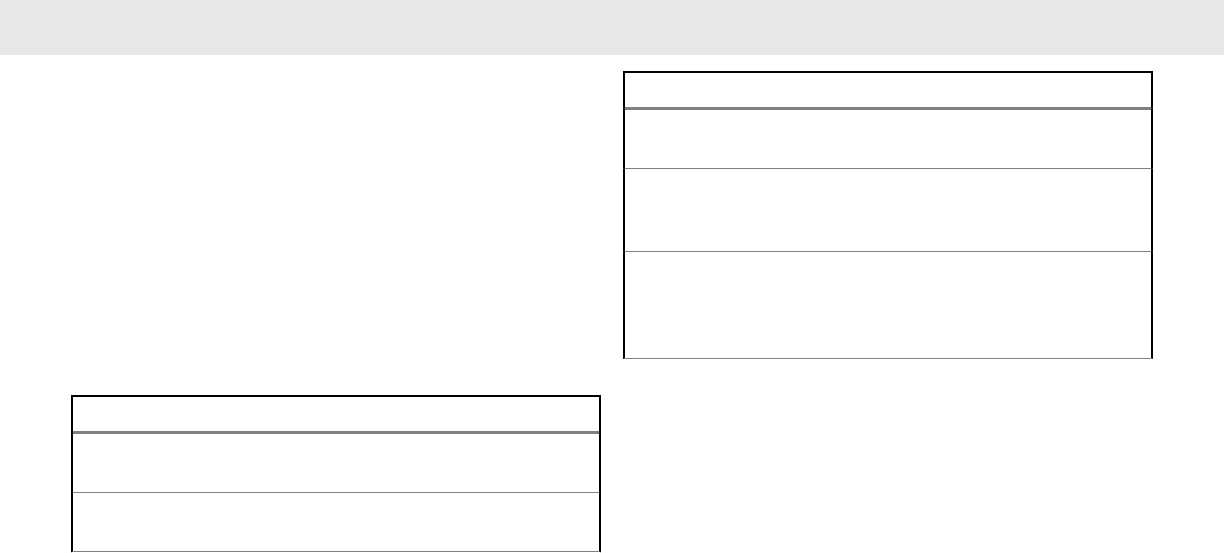
Using Conventional Squelch Operation
Features
This feature filters out unwanted calls with low signal
strength or channels that have a higher than normal
background noise.
Analog Options
Tone Private Line (PL), Digital Private-Line (DPL), and
carrier squelch can be available (preprogrammed) per
channel.
Mode Result
Carrier squelch (C) You hear all traffic on a
channel.
PL or DPL The radio responds only
to your messages.
Digital Options
One or more of the following options may be
preprogrammed in your radio. Check with your dealer or
system administrator for more information.
Option Result
Digital Carrier-Operated
Squelch (COS) You hear any digital traf-
fic.
Normal Squelch You hear any digital traffic
having the correct net-
work access code.
Selective Switch You hear any digital traffic
having the correct net-
work access code and
correct talkgroup.
Using the PL Defeat Feature
This feature allows you to override any coded squelch (DPL
or PL) that might be preprogrammed to a channel. The
radio also unmutes to any digital activity on a digital
channel.
Place the preprogrammed PL Defeat switch in the
PL Defeat position.
One of the following scenarios occurs:
• You hear any activity on the channel.
• The radio is muted if no activity is present.
English
192 Send Feedback
Draft
NOTE:
When this feature is active, the Carrier
Squelch status indicator is displayed.
Digital PTT ID Support
This feature allows you to see the radio ID (number) of the
radio from whom you are currently receiving a
transmission. This ID, consisting up to a maximum of eight
characters, can be viewed by both the receiving radio and
the dispatcher.
The ID number of your radio is also automatically sent
every time the PTT button is pressed. This is a per-channel
feature. For digital voice transmissions, the ID of your radio
is sent continuously during the voice message.
Smart PTT Feature (Conventional Only)
Smart PTT is a per-personality, programmable feature used
in conventional radio systems to keep radio users from
talking over other radio conversations.
When smart PTT is enabled in your radio, you cannot
transmit on an active channel.
If you try to transmit on an active smart-PTT channel, you
hear an alert tone, and the transmission is inhibited. The
LED lights up solid yellow to indicate that the channel is
busy.
The following table shows the variations of smart PTT:
Mode Description
Transmit Inhibit
on Busy Chan-
nel with Carrier
You cannot transmit if any traffic is
detected on the channel.
Transmit Inhibit
on Busy Chan-
nel with Wrong
Squelch Code
You cannot transmit on an active
channel with a squelch code or (if
secure-equipped) encryption key
other than your own. If the PL code
is the same as yours, the transmis-
sion is not prevented.
Quick-Key Over-
ride Your radio must be preprogram-
med to allow you to use Quick-Key
Override. This feature can work in
conjunction with either of the two
above variations. You can override
the transmit-inhibit state by quick-
keying the radio. In other words,
English
Send Feedback 193
Draft

Mode Description
two PTT button presses within the
preprogrammed time limit.
Transmit Inhibit
This feature is available for APCO 25 trunking, Type II
trunking and Conventional operations for all APX radios.
When Transmit Inhibit feature is enabled, the radio stops all
transmission including voice and data. The radio can
receive messages but is not able to reply the
acknowledgment request of the received message.
User can physically control the transmission of the radio
especially during operation in hazardous environments with
this feature. An environment is considered hazardous when
the power emitted by the radio power amplifier could initiate
an explosion or other dangerous reactions.
When the Transmit Inhibit feature is disabled, the radio
functions according to its normal operations.
The radio sounds alert tone when user enters or exits this
feature and also when PTT is pressed.
NOTE:
Acknowledgement of any messages required from
the radio is not transmitted if the Transmit Inhibition
is enabled.
Enabling Transmit Inhibition
Perform one of the following actions:
• Switch the preprogrammed Transmit Inhibit
switch to Transmit Inhibit enabled.
• or to TxIn. Press the Menu Select button
below TxIn.
• Press the Transmit Inhibit programmable button.
English
194 Send Feedback
Draft
NOTE:
If the user has disabled TX Inhibit via the
menu and then moves the switch to the
position where TX Inhibit is enabled, the new
value overwrites the menu value.
The display shows Tx inhibit on. You hear a
sequence of short, low-high tones to indicate
transmission is inhibited.
Pressing PTT triggers the radio sounds a constant short,
low-pitched tone (reject tone).
NOTE:
The status of the Transmit Inhibit does not change
after the radio powers up.
Disabling Transmit Inhibition
Perform one of the following actions:
• or to TxIn. Press the Menu Select button
below TxIn.
• Press the Transmit Inhibit programmable button.
NOTE:
If the user has disabled TX Inhibit via the
softkey and then moves the switch to the
position where TX Inhibit is enabled, the new
value overwrites the menu value.
The display shows Tx inhibit off. You hear a
sequence of short, high-low tone (Transmit Inhibit
Off tone) to indicate transmission is back to normal
operation.
IMPRES Battery Annunciator
This feature displays the current capacity and charges
cycles of your battery when an IMPRES ™ Battery is
powering your radio. This feature must be enabled in your
radio to see the information.
The information shown are:
Charge Percentage
Percentage of current battery capacity.
Remaining Capacity
Remaining power of the battery in mAh.
Estimated Charges
Number of charges cycles the battery has gone
through.
English
Send Feedback 195
Draft
Accessing the Battery Info screen
1 or to Batt.
2Press the Menu Select button directly below Batt.
The display shows the details of the battery.
3To return to the Home screen, press the Menu
Select button directly below Exit.
General Radio Information
Your radio contains information on the following:
• Radio Information
• IP Display
• Control Assignments
• Soft ID (If enabled)
NOTE:
The radio automatically exits the feature, if the
feature inactivity timer is enabled, when the radio is
left idle and the timer expires. You hear the Menu
Inactive Exit Tone upon feature exit.
Accessing the Radio Information
This feature displays the following radio information:
• Host Version
• Secure Version
• Model Number
• ESN
• Flash Code
• Tuning Version
• Option Board Type (optional)
• Option Board Bluetooth Address (optional)
• Expansion Board Type (optional)
• MFK Secondary Function
• DSP Version
• KG (Secure Algorithm)
• Serial Number
• Flash Size & Type
• RF Band(s)
• Processor Version
• Option Board Serial Number (optional)
English
196 Send Feedback
Draft
• Option Board Software Version (optional)
• Language Pack ID and Version (only when the
language of the display is set to non-English)
NOTE:
To return to the Home screen, press at any
time.
1Perform one of the following actions:
• Press the preprogrammed Info button.
• or to Info and press the Menu Select
button directly below Info.
2 or to Radio Info and press the Menu
Select button directly below Sel.
The display shows the Information screen.
3Perform one of the following actions:
• or to scroll through the various
information.
• To return to the previous screen, press the Menu
Select button directly below Back.
• Press to return to the Home screen .
Viewing the IP Information
This feature displays the device name, IP address, and
status of your radio.
NOTE:
The device name of your radio is preprogrammed.
Check with your dealer or system administrator for
more information.
1Perform one of the following actions:
• Press the preprogrammed Info button.
• or to Info and press the Menu Select
button directly below Info.
2 or to IP Info and press the Menu Select
button directly below Sel.
The display shows the IP Info screen.
3Perform one of the following actions:
• or to scroll through the various
information.
English
Send Feedback 197
Draft
• Press the Menu Select button directly below
Back to return to the previous screen.
• Press to return to the Home screen.
Viewing the Control Assignments
This feature displays the programmable radio functions
assigned to the controls of your radio for the currently
selected channel.
See Programmable Features on page 42 for more
information on the various programmable features of your
radio.
1Perform one of the following actions:
• Press the preprogrammed Info button.
• or to Info and press the Menu Select
button directly below Info.
2 or to Control map and press the Menu
Select button directly below Sel.
The display shows the Control Map screen.
3Perform one of the following actions:
• or to scroll through the various
information.
• Press the Menu Select button directly below
Back to return to the previous screen.
• Press to return to the Home screen.
Editing the Soft ID
Your radio must be preprogrammed to allow you to use this
feature.
This feature allows you to change your username.
1Perform one of the following actions:
• Press the preprogrammed Info button.
• or to Info and press the Menu Select
button directly below Info.
2 or to Soft ID and press the Menu Select
button directly below Sel.
The display shows the current Soft ID.
3Perform one of the following actions:
English
198 Send Feedback
Draft

• Press the Menu Select button directly below
Edit to edit the current Soft ID.
• Press the Menu Select button directly below
Back to return to the previous screen.
A blinking cursor appears in the Edit Soft ID screen.
4Use the keypad to edit the text.
5Perform one of the following actions:
• Press the Menu Select button directly below Ok
to save the new Soft ID and return to the previous
screen.
• Press the Menu Select button directly below
Cncl to return to the previous screen.
English
Send Feedback 199
Draft

English
This page intentionally left blank.
200
Draft
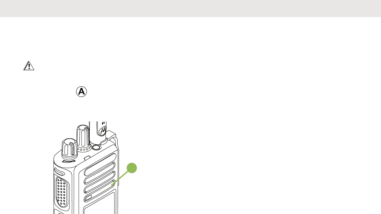
Helpful Tips
Radio Care
CAUTION:
• Your radio casting has a vent port that allows for
pressure equalization in the radio. Never poke
this vent with any objects, such as needles,
tweezers, or screwdrivers.This could create leak
paths into the radio and the radio’s submergibility
will be lost.
A
• The radio with antenna attached properly is
designed to be submersible to a maximum depth
of 1 meter (3.28 feet) and a maximum
submersion time of 30 minutes. Exceeding either
maximum limit or use without antenna may result
in damage to the radio.
• If the radio battery contact area has been
submerged in water, dry and clean the radio
battery contacts before attaching a battery to the
radio. Otherwise, the water could short-circuit the
radio.
• If the radio has been submerged in water, shake
the radio well so that any water that may be
trapped inside the speaker grille and microphone
port can be removed. Otherwise, the water will
decrease the audio quality of the radio.
• Do not disassemble the radio. This could
damage radio seals and result in leak paths into
the radio. Any radio maintenance should be
performed only by a qualified radio technician.
English
Send Feedback 201
Draft
Cleaning Your Radio
CAUTION:
Do not use solvents to clean your radio as most
chemicals may permanently damage the radio
housing and textures.
Do not submerge the radio in the detergent
solution.
To clean the external surfaces of your radio, follow the
procedure described next.
1Combine one teaspoon of mild dishwashing
detergent to one gallon of water (0.5% solution).
2Apply the solution sparingly with a stiff, non-metallic,
shortbristled brush, making sure excess detergent
does not get entrapped near the connectors, controls
or crevices. Dry the radio thoroughly with a soft, lint-
free cloth.
3Clean battery contacts with a lint-free cloth to
remove dirt or grease.
Proper Ways to Handle the Radio
• Do not pound, drop, or throw the radio unnecessarily.
Never carry the radio by the antenna.
• Avoid subjecting the radio to an excess of liquids.
• Do not submerge the radio.
• Avoid subjecting the radio to corrosives, solvents or
chemicals.
• Do not disassemble the radio.
•CAUTION:
Do not use the radio without an accessory
connector or a dust cover in place as
contamination can build up on the contacts.
• When charging the radio using a wall mounted charger,
the radio must be turned off. Otherwise, the Man Down
Alert and Emergency may be accidentally triggered.
Radio Service and Repair
Proper repair and maintenance procedures will assure
efficient operation and long life for this product. A Motorola
maintenance agreement will provide expert service to keep
this and all other communication equipment in perfect
operating condition. A nationwide service organization is
English
202 Send Feedback
Draft
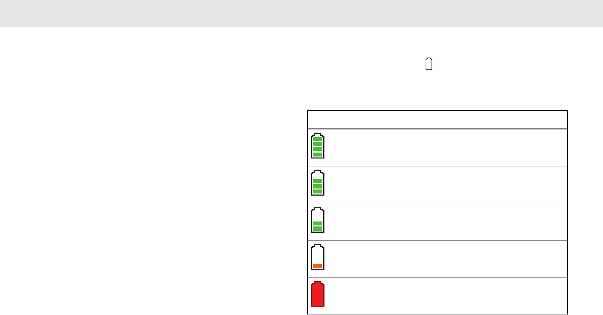
provided by Motorola to support maintenance services.
Through its maintenance and installation program, Motorola
makes available the finest service to those desiring reliable,
continuous communications on a contract basis. For a
contract service agreement, please contact your nearest
Motorola service or sales representative, or an authorized
Motorola dealer.
Battery Care
Battery Charge Status
Your radio can indicate the battery’s charge status through:
• the LED and sounds.
• the fuel gauge icon on the display.
You can also check the battery charge status via the menu
entry. See IMPRES Battery Annunciator on page 195 for
more information.
LED and Sounds
When your battery is low:
• the LED blinks red when the PTT button is pressed.
• you hear a low-battery “chirp” (short, high-pitched tone).
Fuel Gauge Icons
A blinking fuel gauge icon ( ) is displayed only when the
battery voltage drops to low level. In this case, replace the
battery with a fully charged one.
Gauge Battery Charge
76% to 100% full 3
51% to 75%3
26% to 50%3
11% to 25%3
10% or less (at 10%, the gauge
begins blinking)
3
English
Send Feedback 203
Draft

Battery Recycling and Disposal
In the U.S. and Canada, Motorola participates in the
nationwide Rechargeable Battery Recycling Corporation
(RBRC) program for battery collection and recycling. Many
retailers and dealers participate in this program.
For the location of the drop-off facility closest to you,
access RBRC's Internet web site at www.rbrc.com or call
1-800-8-BATTERY. This internet site and telephone
number also provide other useful information concerning
recycling options for consumers, businesses, and
governmental agencies.
3These are for IMPRES™ battery operation only.
English
204 Send Feedback
Draft

Accessories
The accessory link below is for APX radios. Not all
accessories are FCC certified to operate with all APX
models and/or bandsplits. Please refer to the specific APX
radio price pages for a list of FCC certified accessories or
contact your sales representative for accessory
compatibility.
http://www.motorolasolutions.com/APX
English
Send Feedback 205
Draft

English
This page intentionally left blank.
206
Draft

Maritime Radio Use in the
VHF Frequency Range
Special Channel Assignments
Emergency Channel
If you are in imminent and grave danger at sea and require
emergency assistance, use VHF Channel 16 to send a
distress call to nearby vessels and the United States Coast
Guard. Transmit the following information, in this order:
1“MAYDAY, MAYDAY, MAYDAY.”
2“THIS IS _____________________, CALL SIGN
__________.” State the name of the vessel in distress 3
times, followed by the call sign or other identification of
the vessel, stated 3 times.
3Repeat “MAYDAY” and the name of the vessel.
4“WE ARE LOCATED AT _______________________.”
State the position of the vessel in distress, using any
information that will help responders to locate you, e.g.:
• latitude and longitude
• bearing (state whether you are using true or
magnetic north)
• distance to a well-known landmark
• vessel course, speed or destination
5State the nature of the distress.
6Specify what kind of assistance you need.
7State the number of persons on board and the number
needing medical attention, if any.
8Mention any other information that would be helpful to
responders, such as type of vessel, vessel length and/or
tonnage, hull color, etc.
9“OVER.”
10 Wait for a response.
11 If you do not receive an immediate response, remain by
the radio and repeat the transmission at intervals until
you receive a response. Be prepared to follow any
instructions given to you.
Non-Commercial Call Channel
For non-commercial transmissions, such as fishing reports,
rendezvous arrangements, repair scheduling, or berthing
information, use VHF Channel 9.
English
Send Feedback 207
Draft
Operating Frequency Requirements
A radio designated for shipboard use must comply with
Federal Communications Commission Rule Part 80 as
follows:
• on ships subject to Part II of Title III of the
Communications Act, the radio must be capable of
operating on the 156.800 MHz frequency.
• on ships subject to the Safety Convention, the radio
must be capable of operating:
- in the simplex mode on the ship station transmitting
frequencies specified in the 156.025 – 157.425 MHz
frequency band, and
- in the semiduplex mode on the two frequency
channels specified in the table below.
NOTE:
Simplex channels 3, 21, 23, 61, 64, 81, 82, and 83
cannot be lawfully used by the general public in US
waters.
Additional information about operating requirements
in the Maritime Services can be obtained from the
full text of FCC Rule Part 80 and from the US Coast
Guard.
Table 1: VHF Marine Channel List
Channel Num-
ber Frequency (MHz)
Transmit Receive
1 156.050 160.650
2 156.100 160.700
* 156.150 160.750
4 156.200 160.800
5 156.250 160.850
6 156.300 –
7 156.350 160.950
8 156.400 –
9 156.450 156.450
10 156.500 156.500
11 156.550 156.550
12 156.600 156.600
13** 156.650 156.650
14 156.700 156.700
Table continued…
English
208 Send Feedback
Draft

15** 156.750 156.750
16 156.800 156.800
17** 156.850 156.850
18 156.900 161.500
19 156.950 161.550
20 157.000 161.600
* 157.050 161.650
22 157.100 161.700
* 157.150 161.750
24 157.200 161.800
25 157.250 161.850
26 157.300 161.900
27 157.350 161.950
28 157.400 162.000
60 156.025 160.625
* 156.075 160.675
62 156.125 160.725
Table continued…
63 156.175 160.775
* 156.225 160.825
65 156.275 160.875
66 156.325 160.925
67** 156.375 156.375
68 156.425 156.425
69 156.475 156.475
71 156.575 156.575
72 156.625 –
73 156.675 156.675
74 156.725 156.725
75 *** ***
76 *** ***
77** 156.875 –
78 156.925 161.525
79 156.975 161.575
80 157.025 161.625
Table continued…
English
Send Feedback 209
Draft
* 157.075 161.675
* 157.125 161.725
* 157.175 161.775
84 157.225 161.825
85 157.275 161.875
86 157.325 161.925
87 157.375 161.975
88 157.425 162.025
NOTE:
* Simplex channels 3, 21, 23, 61, 64, 81, 82, and 83
cannot be lawfully used by the general public in US
waters.
** Low power (1 W) only.
*** Guard band.
NOTE:
A – in the Receive column indicates that the
channel is transmit only.
Declaration of Compliance for the
Use of Distress and Safety
Frequencies
The radio equipment does not employ a modulation other
than the internationally adopted modulation for maritime
use when it operates on the distress and safety frequencies
specified in RSS-182 Section 7.3.
Technical Parameters for Interfacing
External Data Sources
RS232 USB SB9600
Input Volt-
age (Volts
Peak-to-
peak)
18V 3.6V 5V
Max Data
Rate 115 Kbps 12 Mbps 9.6 Kbps
Impe-
dance 5000 Ohm 90 Ohm 120 Ohm
English
210 Send Feedback
Draft

Glossary
This glossary is a list of specialized terms used in this
manual.
ACK
Acknowledgment of communication.
Active Channel
A channel that has traffic on it.
Analog Signal
An RF signal that has a continuous nature rather than a
pulsed or discrete nature.
ARS
Automatic Registration Service
ASTRO 25
Motorola standard for wireless digital trunked
communications.
ASTRO Conventional
Motorola standard for wireless digital conventional
communications.
Autoscan
A feature that allows the radio to automatically scan the
members of a scan list.
Bluetooth
Bluetooth is an open wireless technology standard for
exchanging data over short distances from fixed and
mobile devices with high levels of security.
Bluetooth Pairing
Bluetooth pairing occurs when two bluetooth devices
exchanged a passkey to form a paired Bluetooth
wireless connection.
Call Alert
Privately page an individual by sending an audible tone.
Carrier Squelch
Feature that responds to the presence of an RF carrier
by opening or unmuting (turning on) a receiver’s audio
circuit. A squelch circuit silences the radio when no
signal is being received so that the user does not have
to listen to “noise”.
Central Controller
A software-controlled, computer-driven device that
receives and generates data for the trunked radios
assigned to it. It monitors and directs the operations of
the trunked repeaters.
English
Send Feedback 211
Draft

Channel
A group of characteristics such as transmit/ receive
frequency pairs, radio parameters, and encryption
encoding.
Control Channel
In a trunking system, one of the channels that is used to
provide a continuous, two-way/ data communications
path between the central controller and all radios on the
system.
Conventional
Typically refers to radio-to-radio communications,
sometimes through a repeater (see Trunking).
Conventional Scan List
A scan list that includes only conventional channels.
COTS
Commercial Off-The-Shelf
Cursor
A visual tracking marker (a blinking line) that indicates a
location on the display.
Deadlock
Displayed by the radio after three failed attempts to
unlock the radio. The radio must be powered off and on
prior to another attempt.
Digital Private Line (DPL)
A type of coded squelch using data bursts. Similar to PL
except a digital code is used instead of a tone.
Digital Signal
An RF signal that has a pulsed, or discrete, nature,
rather than a continuous nature.
Dispatcher
An individual who has radio system management
duties.
DSP
Digital Signal Processing
Dynamic Regrouping
A feature that allows the dispatcher to temporarily
reassign selected radios to a single special channel so
they can communicate with each other.
DSR
Dynamic System Resilience
EID
Encrypted Integrated Data
ESN
Electrical Serial Number
English
212 Send Feedback
Draft

Failsoft
A feature that allows communications to take place
even though the central controller has failed. Each
trunked repeater in the system transmits a data word
informing every radio that the system has gone into
failsoft.
FCC
Federal Communications Commission.
FMFrequency Modulation
Hang Up
Disconnect.
Home screen
The first display information after the radio completes its
self test.
IV&D
Integrated Voice and Data
KVL
Key-variable loader: A device for loading encryption
keys into the radio.
LCD
Liquid crystal display.
Man Down
A life-saving feature that senses the radio user may be
in trouble by monitoring the whether the radio is in a
vertical or horizontal position or whether the radio is
motionless. When this feature is triggered, the radio
alerts the user with audio and visual alerts. It can also
trigger Emergency Alarm the Post-Alert Timer is not
cancelled.
MCW
Mission Critical Wireless
MDC
Motorola Data Communication
Menu Entry
A software-activated feature shown at the bottom of the
display – selection of these features is controlled by the
, , and buttons.
Monitor
Check channel activity by pressing the Monitor button. If
the channel is clear, you hear static. If the channel is in
use, you hear conversation. It also serves as a way to
check the volume level of the radio, since the radio
“opens the squelch” when the monitor button is
pressed.
English
Send Feedback 213
Draft

Multi-Function Knob
It works as a power on/off button, provides primary and
secondary functions like volume change and mode
change.
Multi-System Talkgroup Scan List
A scan list that can include both talkgroups (trunked)
and channels (conventional).
Network Access Code
Network Access Code (NAC) operates on digital
channels to reduce voice channel interference between
adjacent systems and sites.
Non-Tactical/ Revert
The user talks on a preprogrammed emergency
channel. The emergency alarm is sent out on this same
channel.
OTAR
Over-the-air rekeying.
Page
A one-way alert, with audio and/or display messages.
Personality
A set of unique features specific to a radio.
PIN
Personal Identification Number
PremierOne
A software application which streamlines critical real
time operations and simplifies system administration to
deliver accurate, consistent and integrated information
remotely to the requestors.
Preprogrammed
Refers to a software feature that has been activated by
a qualified radio technician.
Private (Conversation) Call
A feature that lets you have a private conversation with
another radio user in the talkgroup.
Private Line (PL)
A sub-audible tone that is transmitted such that only
receivers decoding the tone receives it.
Programmable
Refers to a radio control that can have a radio feature
assigned to it.
PTT
Push-To-Talk. The PTT button engages the transmitter
and puts the radio in transmit (send) operation when
pressed.
English
214 Send Feedback
Draft

Radio Frequency (RF)
The part of the general frequency spectrum between
the audio and infrared light regions (about 10 kHz to
10,000,000 MHz).
Repeater
A conventional radio feature, where you talk through a
receive/transmit facility that re-transmits received
signals, in order to improve communications range and
coverage.
Selective Call
A feature that allows you to call a selected individual,
intended to provide privacy and to eliminate the
annoyance of having to listen to conversations of no
interest to you.
Selective Switch
Any digital P25 traffic having the correct Network
Access Code and the correct talkgroup.
Squelch
Special electronic circuitry, added to the receiver of a
radio, that reduces, or cuts off, unwanted signals before
they are heard in the speaker.
SSISynchronous Serial Interface
Standby
An operating condition whereby the radio’s speaker is
muted but still continues to receive data.
Status Calls
Pre-defined text messages that allow the user to send a
conditional message without talking.
Tactical/ Non-Revert
The user talks on the channel that was selected before
the radio entered the emergency state.
Talkaround
Bypass a repeater and talk directly to another unit for
easy local unit-to-unit communications.
Talkgroup
An organization or group of radio users who
communicate with each other using the same
communication path.
TMS
Text Messaging Service
Trunking
The automatic sharing of communications paths
between a large number of users (see Conventional).
Trunking Priority Monitor Scan List
A scan list that includes talkgroups that are all from the
same trunking system.
English
Send Feedback 215
Draft

USK
Unique Shadow Key.
UTC
Coordinated Universal Time. The international time
standard (formerly Greenwich Mean Time, or GMT).
Zero hours UTC is midnight in Greenwich, England,
which is located at 0 degrees longitude. Everything east
of Greenwich (up to 180 degrees) is later in time;
everything west is earlier. There are 42 time authorities
around the world that are constantly synchronizing with
each other. Abbreviated as UTC (English backronym =
Universal Time, Coordinated), it is also known as Zulu
(Z) Time.
Zone
A grouping of channels.
English
216 Send Feedback
Draft
Limited Warranty
MOTOROLA COMMUNICATION
PRODUCTS
I. WHAT THIS WARRANTY COVERS
AND FOR HOW LONG:
MOTOROLA SOLUTIONS, INC. (“MOTOROLA”) warrants
the MOTOROLA manufactured Communication Products
listed below (“Product”) against defects in material and
workmanship under normal use and service for a period of
time from the date of purchase as scheduled below:
ASTRO APX 1000+ Port-
able Units One (1) Year
Product Accessories One (1) Year
For LACR region:
ASTRO APX 1000+Porta-
ble Units Three (3) Years
Product Accessories One (1) Year
MOTOROLA, at its option, will at no charge either repair
the Product (with new or reconditioned parts), replace it
(with a new or reconditioned Product), or refund the
purchase price of the Product during the warranty period
provided it is returned in accordance with the terms of this
warranty. Replaced parts or boards are warranted for the
balance of the original applicable warranty period. All
replaced parts of Product shall become the property of
MOTOROLA.
This express limited warranty is extended by MOTOROLA
to the original end user purchaser only and is not
assignable or transferable to any other party. This is the
complete warranty for the Product manufactured by
MOTOROLA. MOTOROLA assumes no obligations or
liability for additions or modifications to this warranty unless
made in writing and signed by an officer of MOTOROLA.
Unless made in a separate agreement between
MOTOROLA and the original end user purchaser,
MOTOROLA does not warrant the installation, maintenance
or service of the Product.
English
Send Feedback 217
Draft

MOTOROLA cannot be responsible in any way for any
ancillary equipment not furnished by MOTOROLA which is
attached to or used in connection with the Product, or for
operation of the Product with any ancillary equipment, and
all such equipment is expressly excluded from this
warranty. Because each system which may use the
Product is unique, MOTOROLA disclaims liability for range,
coverage, or operation of the system as a whole under this
warranty.
MOTOROLA offers the following optional extended service
contracts.
SERVICE FROM THE START (SfS) COMPREHENSIVE
Provides for extended hardware repair coverage
INCLUDING CHEMICAL, LIQUID, FIRE, AND OTHER
PHYSICAL DAMAGE. Comprehensive coverage is
available in conjunction with MOTOROLA’S standard
Commercial Warranty and starts from the FIRST DAY the
radio is put into use. Service performed under this plan
consists of repair or replacement of the covered equipment
as set forth in the terms and conditions. Repairs will be
made only at the designated MOTOROLA repair depot.
Local services are not included. MOTOROLA will pay the
inbound shipping charges only with use of the MOTOROLA
designated delivery service. MOTOROLA will pay for
outbound shipping via MOTOROLA'S normal shipping
methods.
SERVICE FROM THE START (SfS) LITE
Provides extended hardware normal wear and tear repair
coverage beginning AFTER MOTOROLA’S standard
Commercial Warranty period expires. Service performed
under this plan consists of repair of the covered equipment
as set forth in the terms and conditions. Repairs will be
made only at the designated MOTOROLA repair depot.
Local services are not included. MOTOROLA will pay for
outbound shipping via MOTOROLA'S normal shipping
methods.
II. GENERAL PROVISIONS:
This warranty sets forth the full extent of MOTOROLA'S
responsibilities regarding the Product. Repair, replacement
or refund of the purchase price, at MOTOROLA’s option, is
the exclusive remedy. THIS WARRANTY IS GIVEN IN
LIEU OF ALL OTHER EXPRESS WARRANTIES. IMPLIED
WARRANTIES, INCLUDING WITHOUT LIMITATION,
IMPLIED WARRANTIES OF MERCHANTABILITY AND
FITNESS FOR A PARTICULAR PURPOSE, ARE LIMITED
TO THE DURATION OF THIS LIMITED WARRANTY. IN
NO EVENT SHALL MOTOROLA BE LIABLE FOR
DAMAGES IN EXCESS OF THE PURCHASE PRICE OF
English
218 Send Feedback
Draft

THE PRODUCT, FOR ANY LOSS OF USE, LOSS OF
TIME, INCONVENIENCE, COMMERCIAL LOSS, LOST
PROFITS OR SAVINGS OR OTHER INCIDENTAL,
SPECIAL OR CONSEQUENTIAL DAMAGES ARISING
OUT OF THE USE OR INABILITY TO USE SUCH
PRODUCT, TO THE FULL EXTENT SUCH MAY BE
DISCLAIMED BY LAW.
III. STATE LAW RIGHTS:
SOME STATES DO NOT ALLOW THE EXCLUSION OR
LIMITATION OF INCIDENTAL OR CONSEQUENTIAL
DAMAGES OR LIMITATION ON HOW LONG AN IMPLIED
WARRANTY LASTS, SO THE ABOVE LIMITATION OR
EXCLUSIONS MAY NOT APPLY.
This warranty gives specific legal rights, and there may be
other rights which may vary from state to state.
IV. HOW TO GET WARRANTY
SERVICE:
You must provide proof of purchase (bearing the date of
purchase and Product item serial number) in order to
receive warranty service and, also, deliver or send the
Product item, transportation and insurance prepaid, to an
authorized warranty service location. Warranty service will
be provided by MOTOROLA through one of its authorized
warranty service locations. If you first contact the company
which sold you the Product (e.g., dealer or communication
service provider), it can facilitate your obtaining warranty
service. You can also call MOTOROLA at 1-800-927-2744
US/Canada.
V. WHAT THIS WARRANTY DOES
NOT COVER:
1Defects or damage resulting from use of the Product in
other than its normal and customary manner.
2Defects or damage from misuse, accident, water, or
neglect.
3Defects or damage from improper testing, operation,
maintenance, installation, alteration, modification, or
adjustment.
4Breakage or damage to antennas unless caused directly
by defects in material workmanship.
5A Product subjected to unauthorized Product
modifications, disassembles or repairs (including,
without limitation, the addition to the Product of non-
MOTOROLA supplied equipment) which adversely
English
Send Feedback 219
Draft

affect performance of the Product or interfere with
MOTOROLA's normal warranty inspection and testing of
the Product to verify any warranty claim.
6Product which has had the serial number removed or
made illegible.
7Rechargeable batteries if:
• any of the seals on the battery enclosure of cells are
broken or show evidence of tampering.
• the damage or defect is caused by charging or using
the battery in equipment or service other than the
Product for which it is specified.
8Freight costs to the repair depot.
9A Product which, due to illegal or unauthorized
alteration of the software/firmware in the Product, does
not function in accordance with MOTOROLA’s
published specifications or the FCC certification labeling
in effect for the Product at the time the Product was
initially distributed from MOTOROLA.
10 Scratches or other cosmetic damage to Product
surfaces that does not affect the operation of the
Product.
11 Normal and customary wear and tear.
VI. PATENT AND SOFTWARE
PROVISIONS:
MOTOROLA will defend, at its own expense, any suit
brought against the end user purchaser to the extent that it
is based on a claim that the Product or parts infringe a
United States patent, and MOTOROLA will pay those costs
and damages finally awarded against the end user
purchaser in any such suit which are attributable to any
such claim, but such defense and payments are
conditioned on the following:
1that MOTOROLA will be notified promptly in writing by
such purchaser of any notice of such claim,
2that MOTOROLA will have sole control of the defense of
such suit and all negotiations for its settlement or
compromise, and
3should the Product or parts become, or in
MOTOROLA’s opinion be likely to become, the subject
of a claim of infringement of a United States patent, that
such purchaser will permit MOTOROLA, at its option
and expense, either to procure for such purchaser the
right to continue using the Product or parts or to replace
or modify the same so that it becomes non-infringing or
to grant such purchaser a credit for the Product or parts
as depreciated and accept its return. The depreciation
English
220 Send Feedback
Draft

will be an equal amount per year over the lifetime of the
Product or parts as established by MOTOROLA.
MOTOROLA will have no liability with respect to any claim
of patent infringement which is based upon the combination
of the Product or parts furnished hereunder with software,
apparatus or devices not furnished by MOTOROLA, nor will
MOTOROLA have any liability for the use of ancillary
equipment or software not furnished by MOTOROLA which
is attached to or used in connection with the Product. The
foregoing states the entire liability of MOTOROLA with
respect to infringement of patents by the Product or any
parts thereof.
Laws in the United States and other countries preserve for
MOTOROLA certain exclusive rights for copyrighted
MOTOROLA software such as the exclusive rights to
reproduce in copies and distribute copies of such
MOTOROLA software. MOTOROLA software may be used
in only the Product in which the software was originally
embodied and such software in such Product may not be
replaced, copied, distributed, modified in any way, or used
to produce any derivative thereof. No other use including,
without limitation, alteration, modification, reproduction,
distribution, or reverse engineering of such MOTOROLA
software or exercise of rights in such MOTOROLA software
is permitted. No license is granted by implication, estoppel
or otherwise under MOTOROLA patent rights or copyrights.
VII. GOVERNING LAW:
This Warranty is governed by the laws of the State of
Illinois, U.S.A.
VIII. For Australia Only
This warranty is given by Motorola Solutions Australia Pty
Limited (ABN 16 004 742 312) of Tally Ho Business Park,
10 Wesley Court. Burwood East, Victoria.
Our goods come with guarantees that cannot be excluded
under the Australia Consumer Law. You are entitled to a
replacement or refund for a major failure and compensation
for any other reasonably foreseeable loss or damage. You
are also entitled to have the goods repaired or replaced if
the goods fail to be of acceptable quality and the failure
does not amount to a major failure.
Motorola Solutions Australia’s limited warranty above is in
addition to any rights and remedies you may have under
the Australian Consumer Law. If you have any queries,
please call Motorola Solutions Australia at 1800 457 439.
You may also visit our website: http://
www.motorolasolutions.com/XA-EN/Pages/Contact_Us for
the most updated warranty terms.
English
Send Feedback 221
Draft

English
This page intentionally left blank.
222
Draft