Motorola Solutions 89FT7111 2-Way Portable Radio with Bluetooth, Bluetooth LE and WiFi User Manual USER GUIDE
Motorola Solutions, Inc. 2-Way Portable Radio with Bluetooth, Bluetooth LE and WiFi USER GUIDE
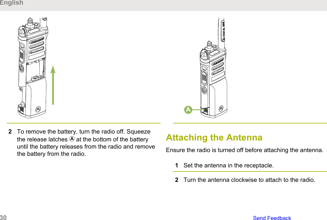
Contents
- 1. Manual
- 2. Safety Manual
- 3. RF Safety Manual
Manual


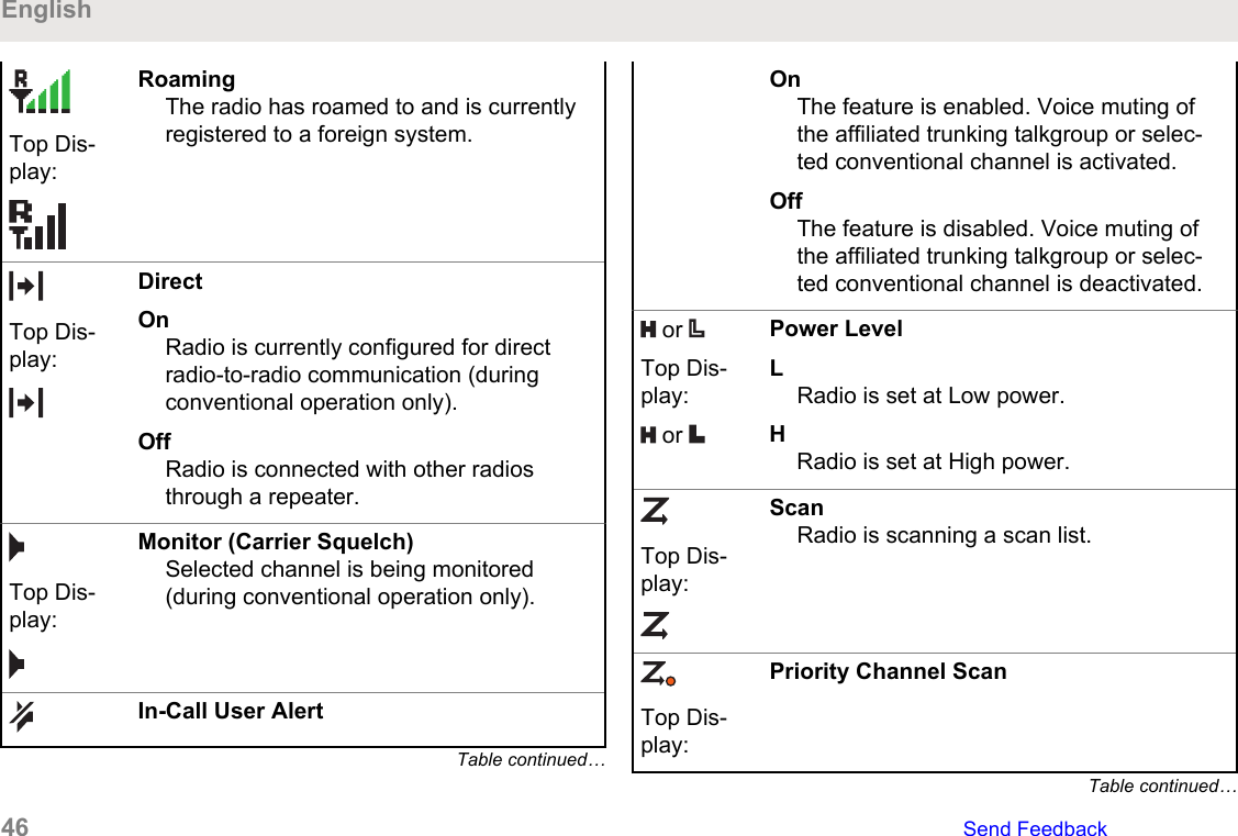
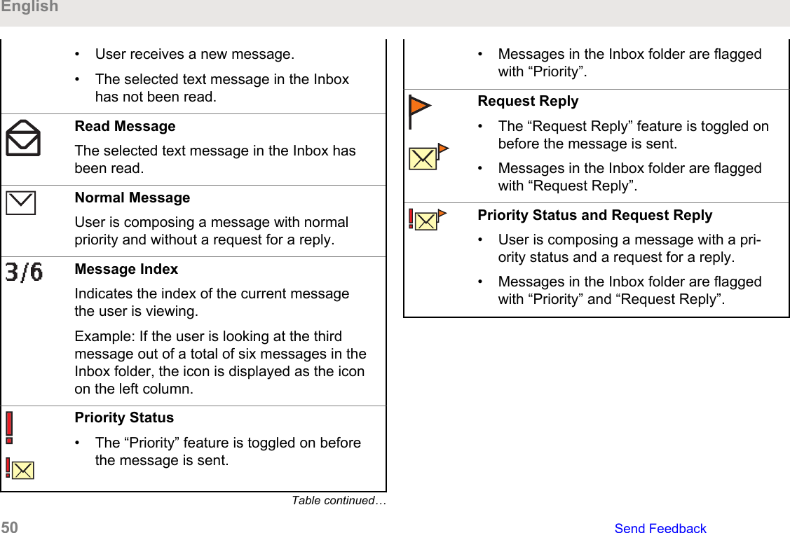
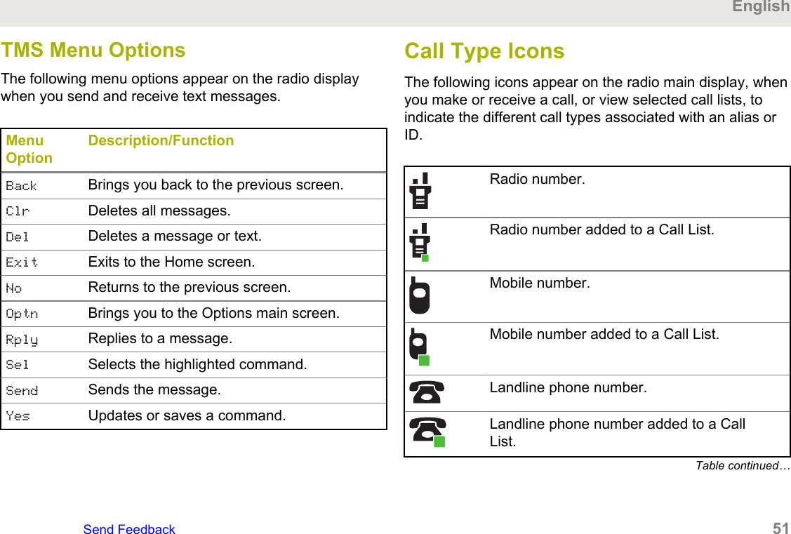
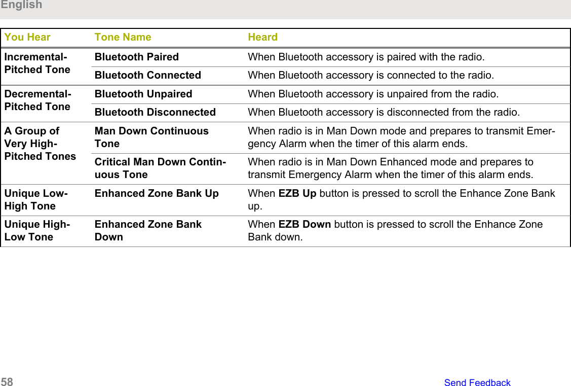
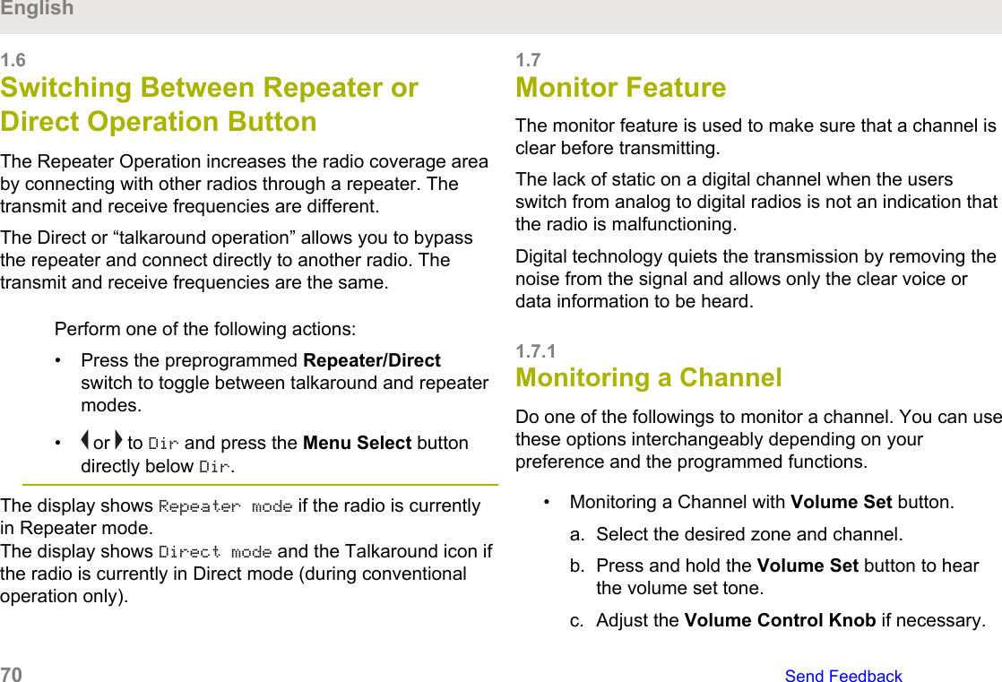

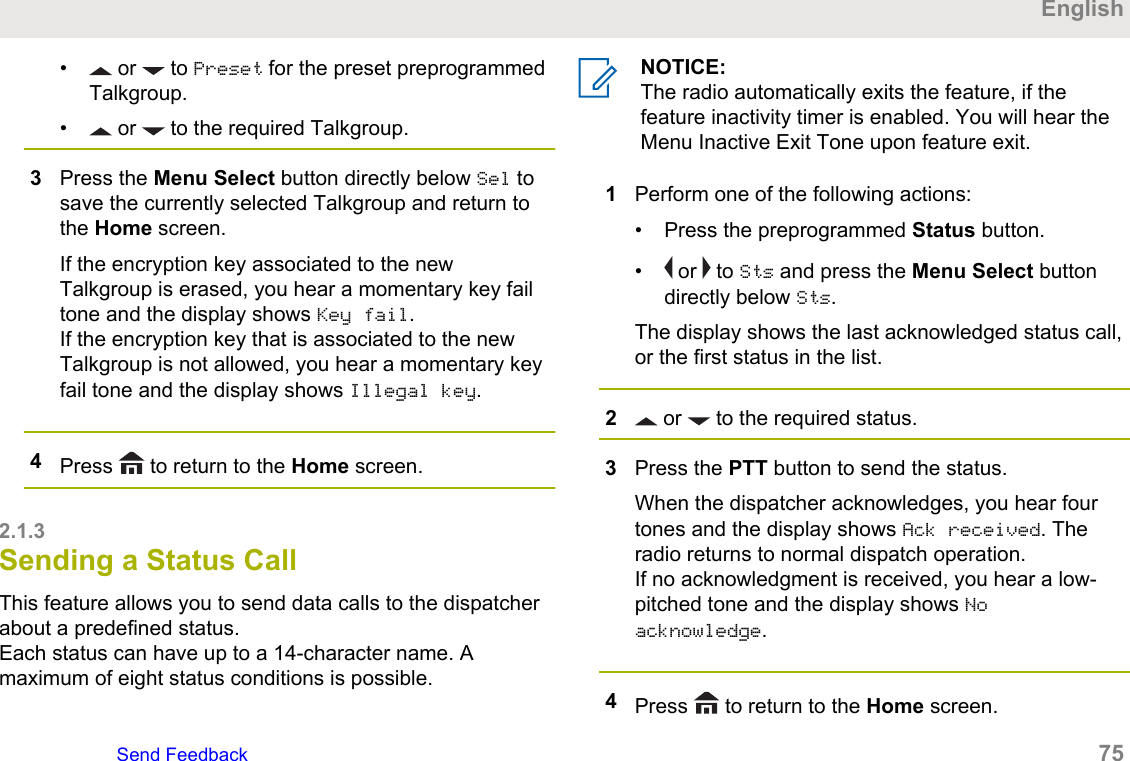
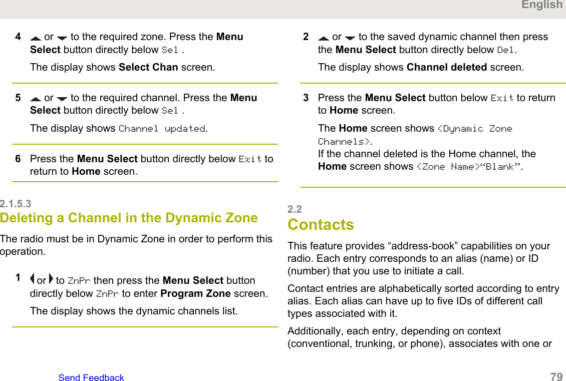

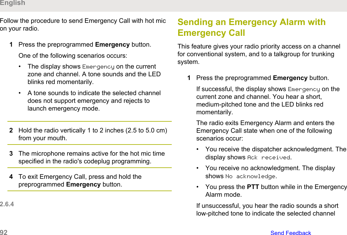
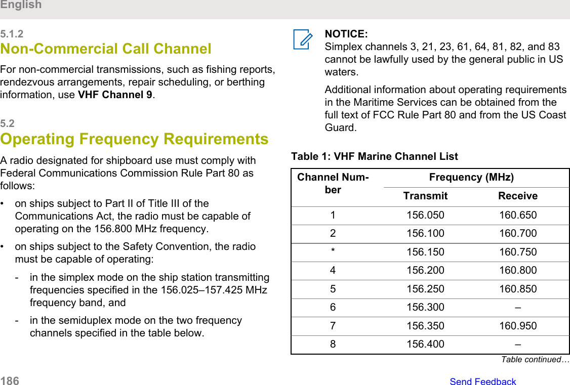
![8Perform one of the following actions:• or to scroll through the address list andselect the required address.• or to [Other Recpnt] and press the MenuSelect button below Edit. When a blinkingcursor appears on the Enter Address screen.9Press the Menu Select button directly below Send orpress the PTT button to send the message.The display shows the Send Message screen andSending msg.If the message is sent, you hear a tone and thedisplay shows Msg sent.If the message is not sent, you hear a low tone, thedisplay shows Send failed and returns to the mainTMS screen.NOTICE:You can append a priority status and/or arequest reply to your message. See PriorityStatus and Request Reply of a New TextMessage on page 109 for more information.2.11.2Priority Status and Request Reply of aNew Text MessageBefore sending your message, you can append a prioritystatus and/or a request reply to your message.2.11.2.1Appending a Priority Status to a TextMessageNOTICE:The Priority Status icon on a message does notimply that the message gets higher priority over theother messages when it is being transmitted. It isjust an indication that can be embedded into amessage to let the receiver know that the messageis important.1Press the Menu Select button directly below Optn .EnglishSend Feedback 109](https://usermanual.wiki/Motorola-Solutions/89FT7111.Manual/User-Guide-3900435-Page-109.png)
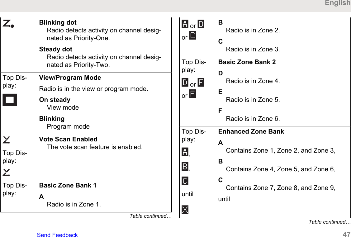
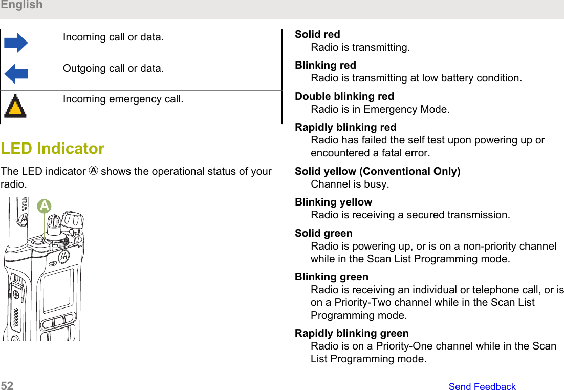
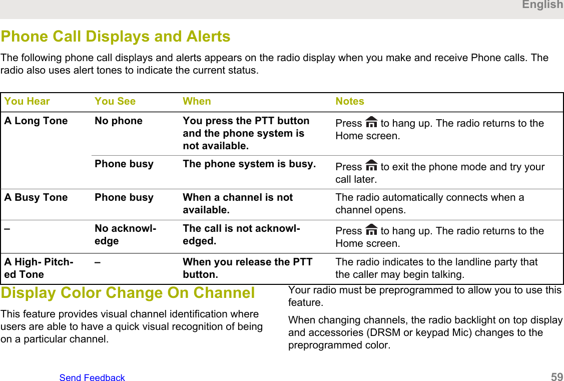
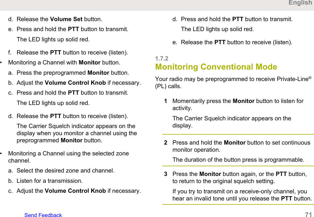
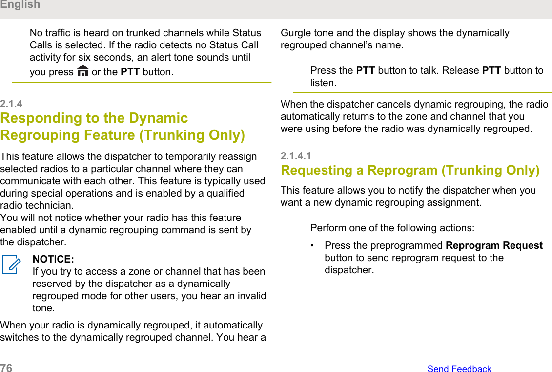
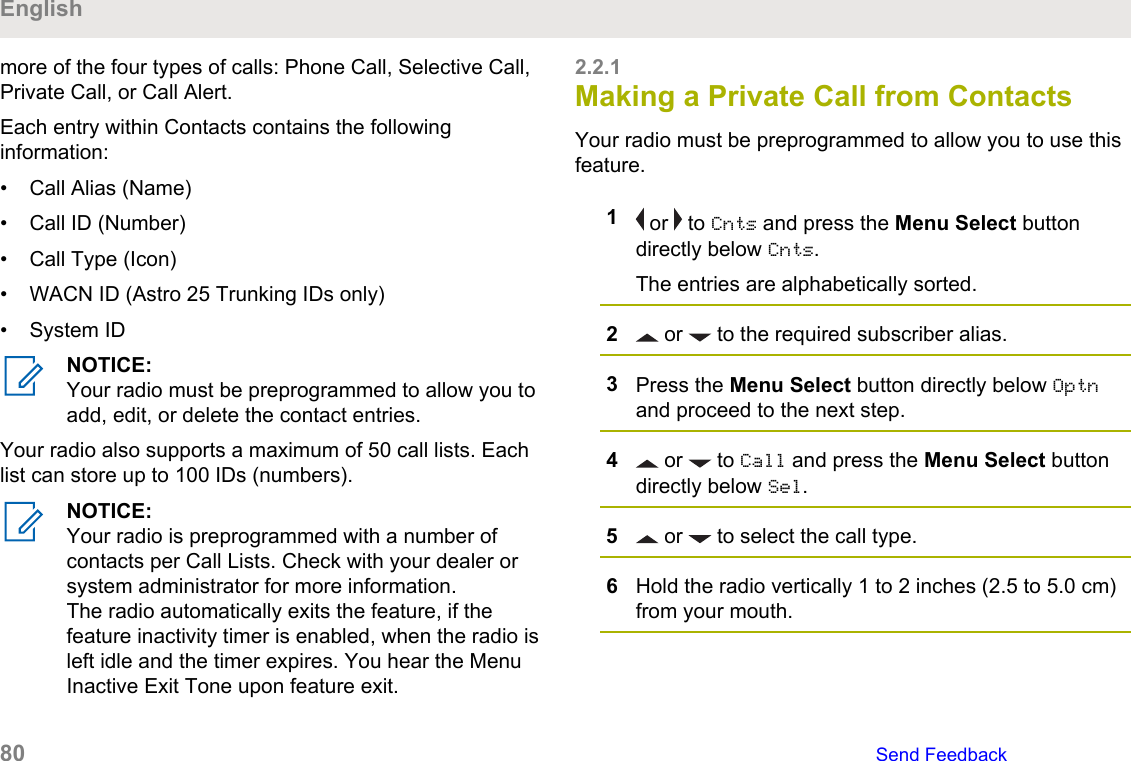
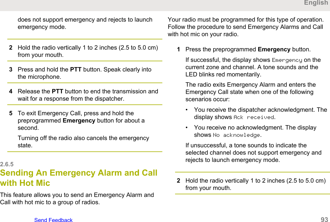
![5To return to the Home screen, press , the PTTbutton, the preprogrammed GPS button or the MenuSelect button directly below Exit.2.13.6Saving a WaypointEnsure that your radio shows the current location on thescreen.1Press the Menu Select button directly below Optn.2Perform one of the following actions:• or to Save as Waypt and press the MenuSelect button directly below Sel.• or to Save as Home and press the MenuSelect button directly below Sel and proceed to step 5.• or to Save as Dest. and press the MenuSelect button directly below Sel and proceed to step 5.3Press the Menu Select button directly below Okonce you are done.One of the following scenarios occur:• The display shows Current loc saved as<Waypoint name>.• The display shows Current loc saved as[Home].• The display shows Current loc saved as[Destination].4To return to the Home screen, press , the PTTbutton, the preprogrammed GPS button or the MenuSelect button directly below Exit.2.13.7Viewing a Saved WaypointEnsure your radio shows the current location on thescreen.1Press the Menu Select button directly below Optn.English126 Send Feedback](https://usermanual.wiki/Motorola-Solutions/89FT7111.Manual/User-Guide-3900435-Page-126.png)

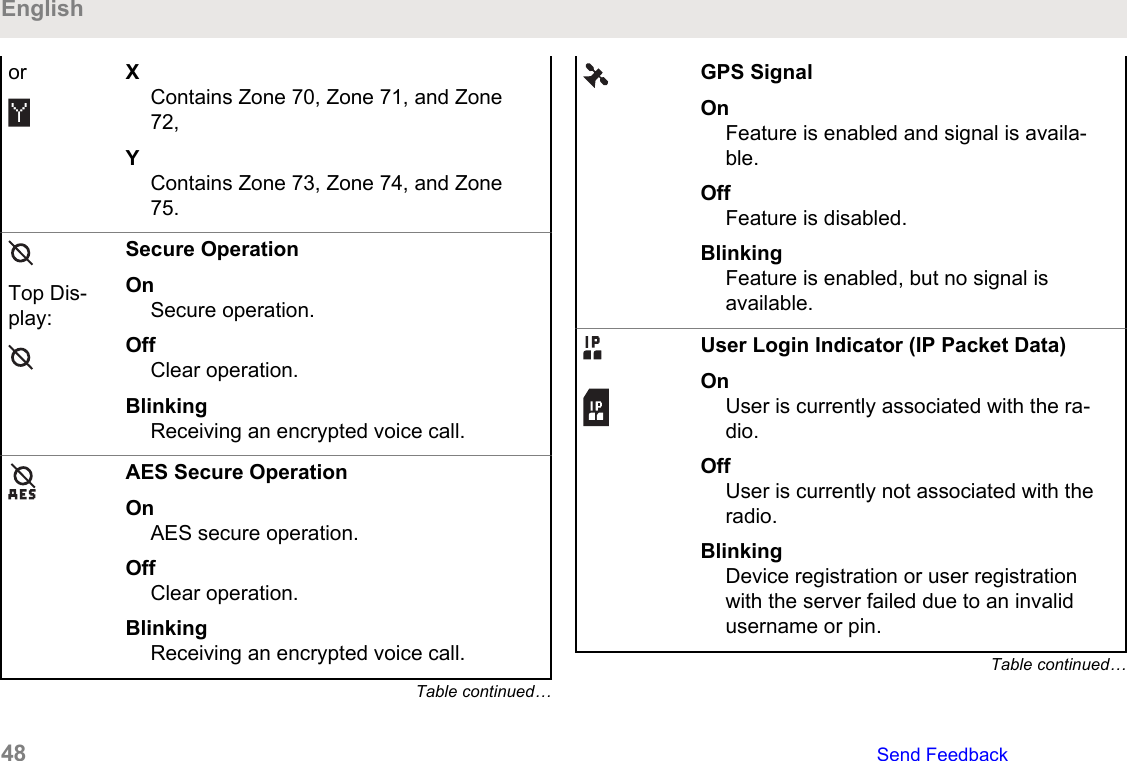
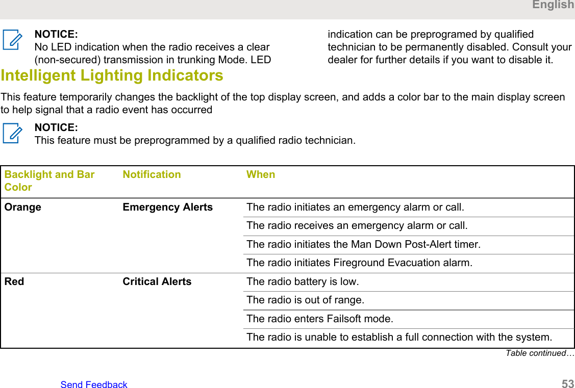
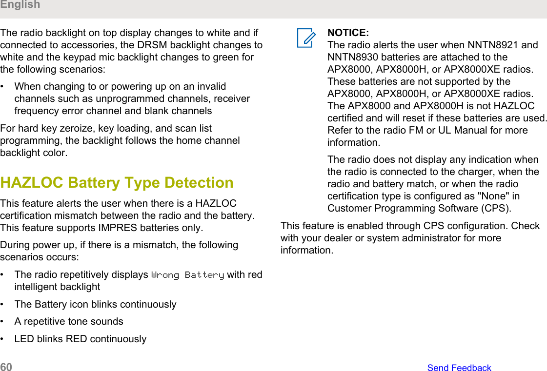
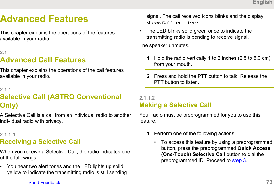
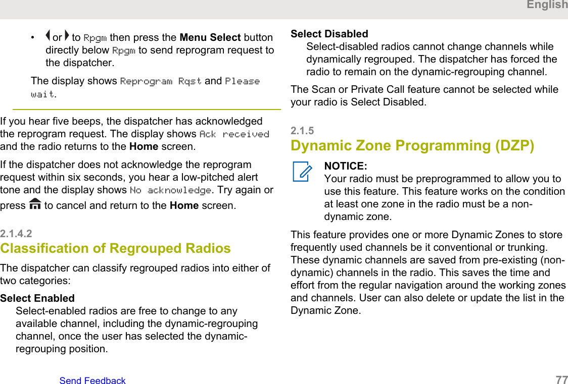
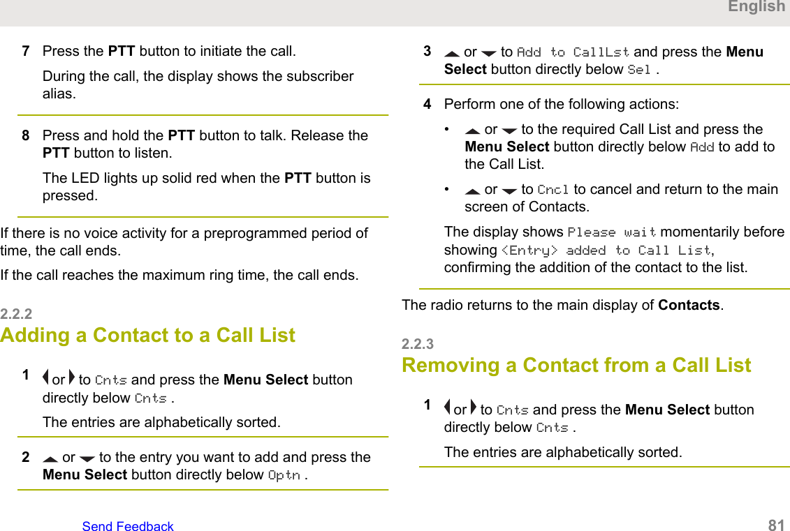
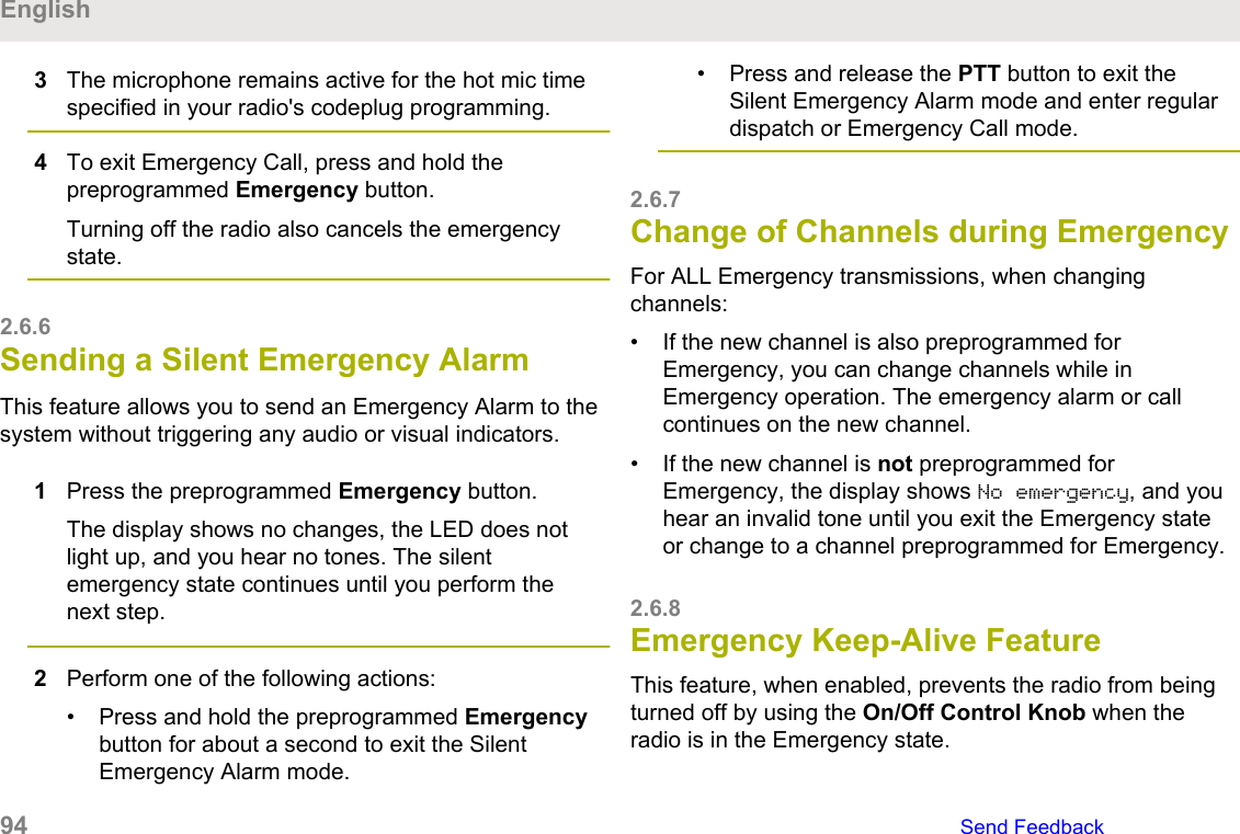
![3 or to Start Alert and press the MenuSelect button directly below Sel.The display shows the Select Site screen.4 or to the desired Site Alias. Press the MenuSelect button directly below Sel.The display shows the Select Alert screen.5 or to select the desired Alert Alias and pressthe Menu Select button directly below Send.The display shows Sending req.If radio is out of range, roaming to a foreign systemor in a failsoft situation, the display shows Reqfailed.If the request is successful, the display shows Reqsuccessful.If the site is not available, the display shows <SiteAlias> not available.If the site does not exist, the display shows <SiteAlias> does not exist.6To return to the Home screen, press the MenuSelect button directly below Exit.If you are at the site designated to receive this alert, youcan hear an alert tone repeated periodically. The displayshows the <Alert Alias> with the intelligent lighting atHome screen.2.19.2Sending SSA Notification to All Sites1 or to SSA.2Press the Menu Select button directly below SSA.The display shows the Site Alert screen.3 or to Start Alert and press the MenuSelect button directly below Sel.The display shows the Select Site screen.4 or to [All Sites] and press the MenuSelect button directly below Sel.The display shows the Select Alert screen.EnglishSend Feedback 155](https://usermanual.wiki/Motorola-Solutions/89FT7111.Manual/User-Guide-3900435-Page-155.png)
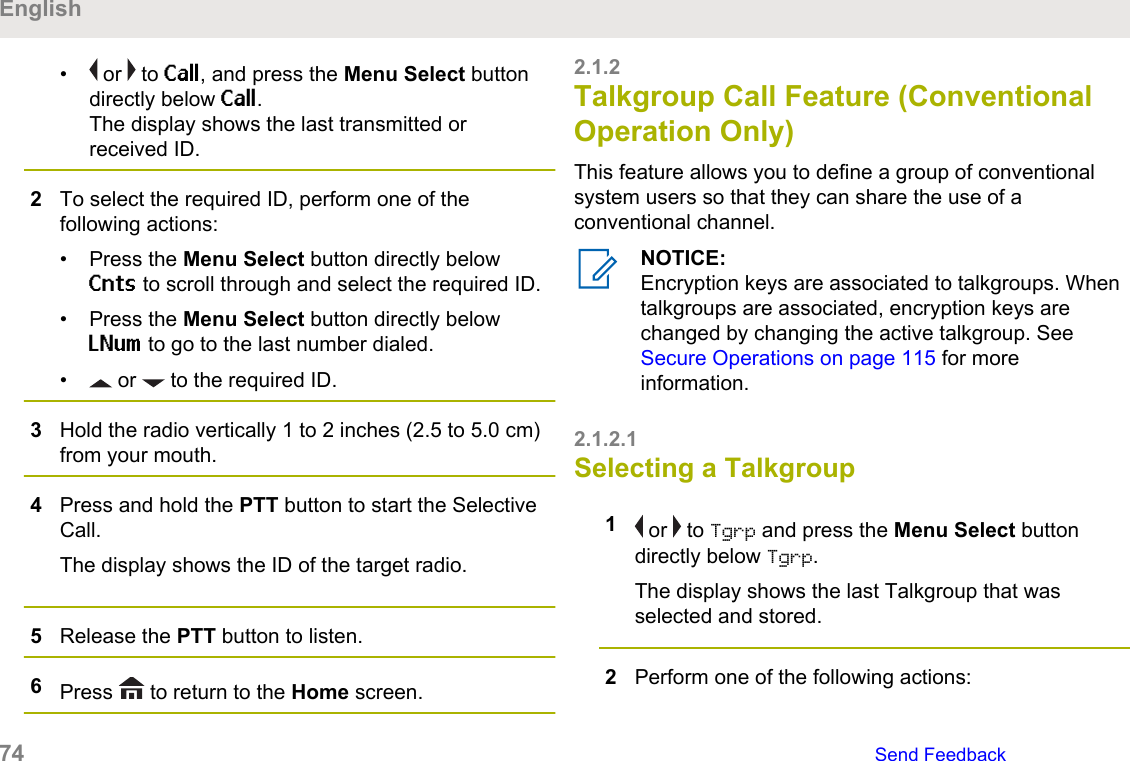
![5 or to select the desired <Alert Alias> andpress the Menu Select button directly below Send.The display shows Sending req.If radio is out of range, roaming to a foreign systemor in a failsoft situation, the display shows Reqfailed.If the request is successful, the display shows Reqsuccessful.If one or more sites are not available, the displayshows Not all sites available. Repeat step 3.6To return to the Home screen, press the MenuSelect button directly below Exit.If you are at the site designated to receive this alert, youcan hear an alert tone repeated periodically. The displayshows the <Alert Alias> with the intelligent lighting atHome screen.2.19.3Sending SSA Notification to AllAvailable Sites1 or to SSA.2Press the Menu Select button directly below SSA.The display shows the Site Alert screen.3 or to Start Alert and press the MenuSelect button directly below Sel.The display shows the Select Site screen.4 or to [All Avail] and press the MenuSelect button directly below Sel.The display shows the Select Alert screen.5 or to select the desired Alert Alias and pressthe Menu Select button directly below Send.The display shows Sending req.If radio is out of range, roaming to a foreign systemor in a failsoft situation, the display shows Reqfailed.English156 Send Feedback](https://usermanual.wiki/Motorola-Solutions/89FT7111.Manual/User-Guide-3900435-Page-156.png)
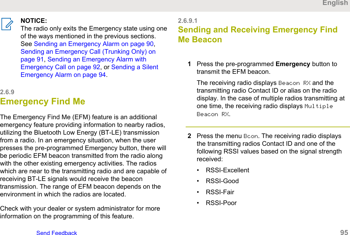
![2.19.5Stopping SSA Notification of All Sites1 or to SSA.2Press the Menu Select button directly below SSA.The display shows the Site Alert screen.3 or to Stop Alert and press the Menu Selectbutton directly below Sel.The display shows the Select Site screen.4 or to [All Sites] and press the MenuSelect button directly below Send.The display shows Sending req.If radio is out of range, roaming to a foreign systemor in a failsoft situation, the display shows Reqfailed.If the request is successful, the display shows Reqsuccessful.If one or more sites are not available, the displayshows Not all sites available. Repeat step 3.5To return to the Home screen, press the MenuSelect button directly below Exit.The SSA Alert for all sites stop.2.19.6Stopping SSA Notification of AllAvailable Sites1 or to SSA.2Press the Menu Select button directly below SSA.The display shows the Site Alert screen.3 or to Stop Alert and press the Menu Selectbutton directly below Sel.The display shows the Select Site screen.English158 Send Feedback](https://usermanual.wiki/Motorola-Solutions/89FT7111.Manual/User-Guide-3900435-Page-158.png)
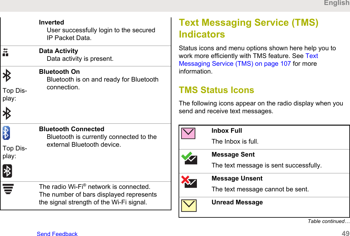
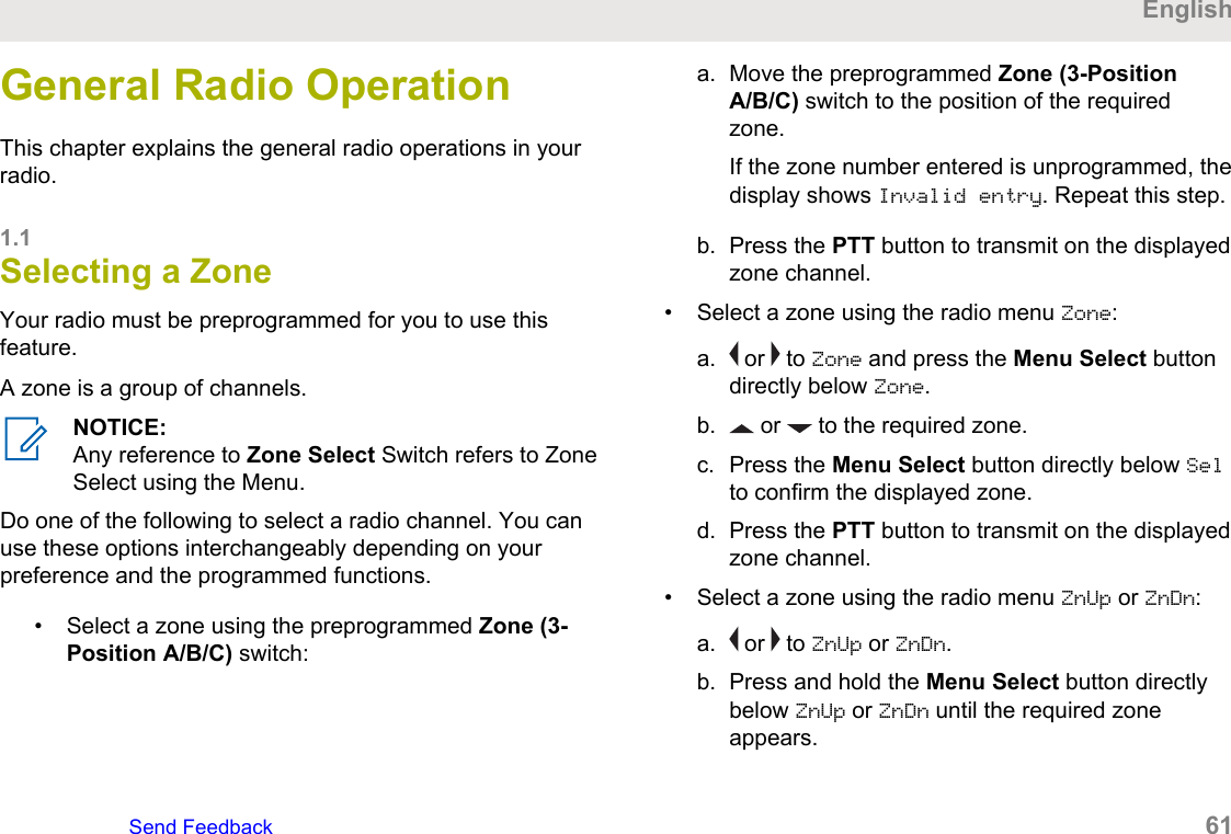
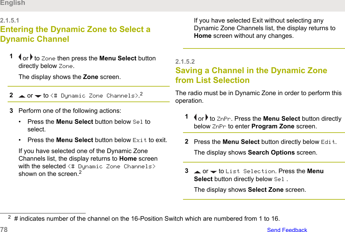
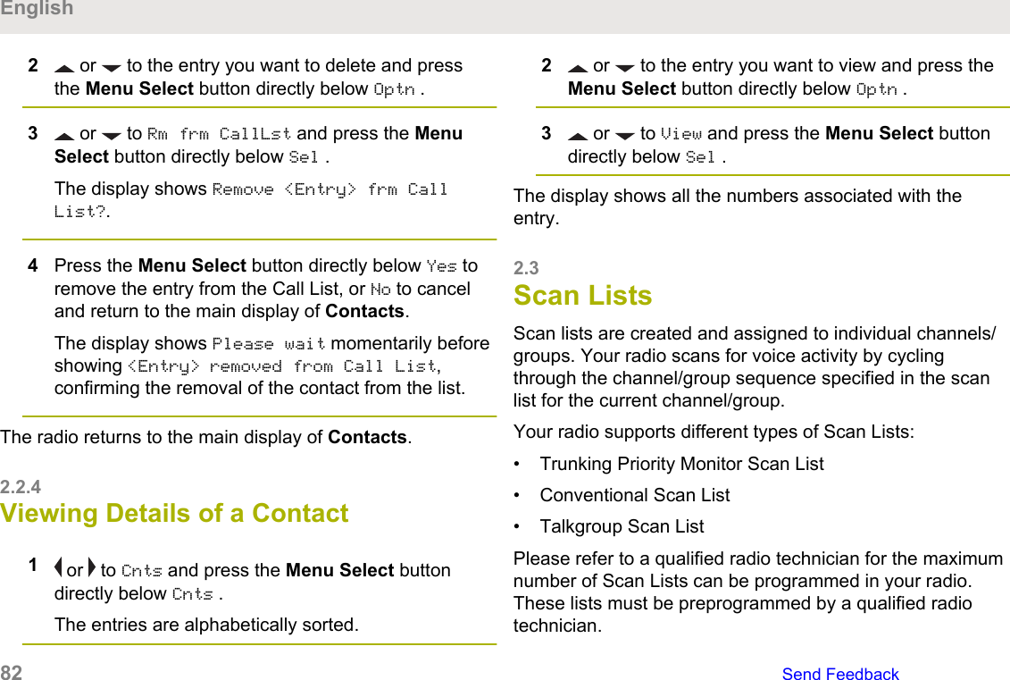
![4 or to [All Avail] and press the MenuSelect button directly below Send.The display shows Sending req.If radio is out of range, roaming to a foreign systemor in a failsoft situation, the display shows Reqfailed.If the request is successful, the display shows Reqsuccessful.5To return to the Home screen, press the MenuSelect button directly below Exit.The SSA Alert for all available sites stop.2.20Wi-FiThis feature allows you to turn Wi-Fi on or off. Wi-Fi can beused for wireless programming of the radio with the RadioManagement tool.NOTICE:This feature is available to capable and orderedoption.Wi-Fi Network Name (SSID) for the radio to connectto must be preprogrammed by a qualified radiotechnician. Check with your dealer or systemadministrator for more information.2.20.1Turning Wi-Fi On or OffDo one of the following to turn Wi-Fi on or off. You can usethe options interchangeably depending on your preferenceand the programmed functions.• Turning Wi-Fi on or off using the preprogrammedbutton:a. To toggle the Wi-Fi on or off, press thepreprogrammed Wi-Fi button.This button must be preprogrammed by aqualified radio technician. Check with your dealeror system administrator for more information.• Turning Wi-Fi on or off using the radio menu button:EnglishSend Feedback 159](https://usermanual.wiki/Motorola-Solutions/89FT7111.Manual/User-Guide-3900435-Page-159.png)