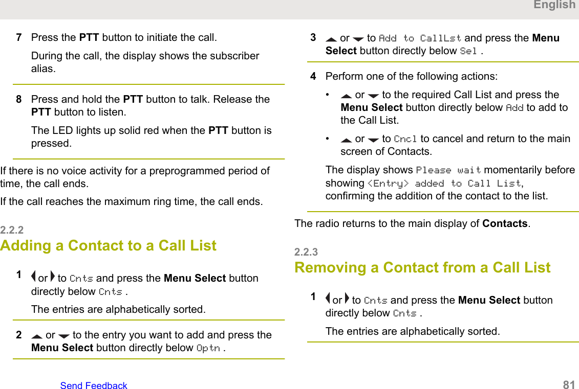
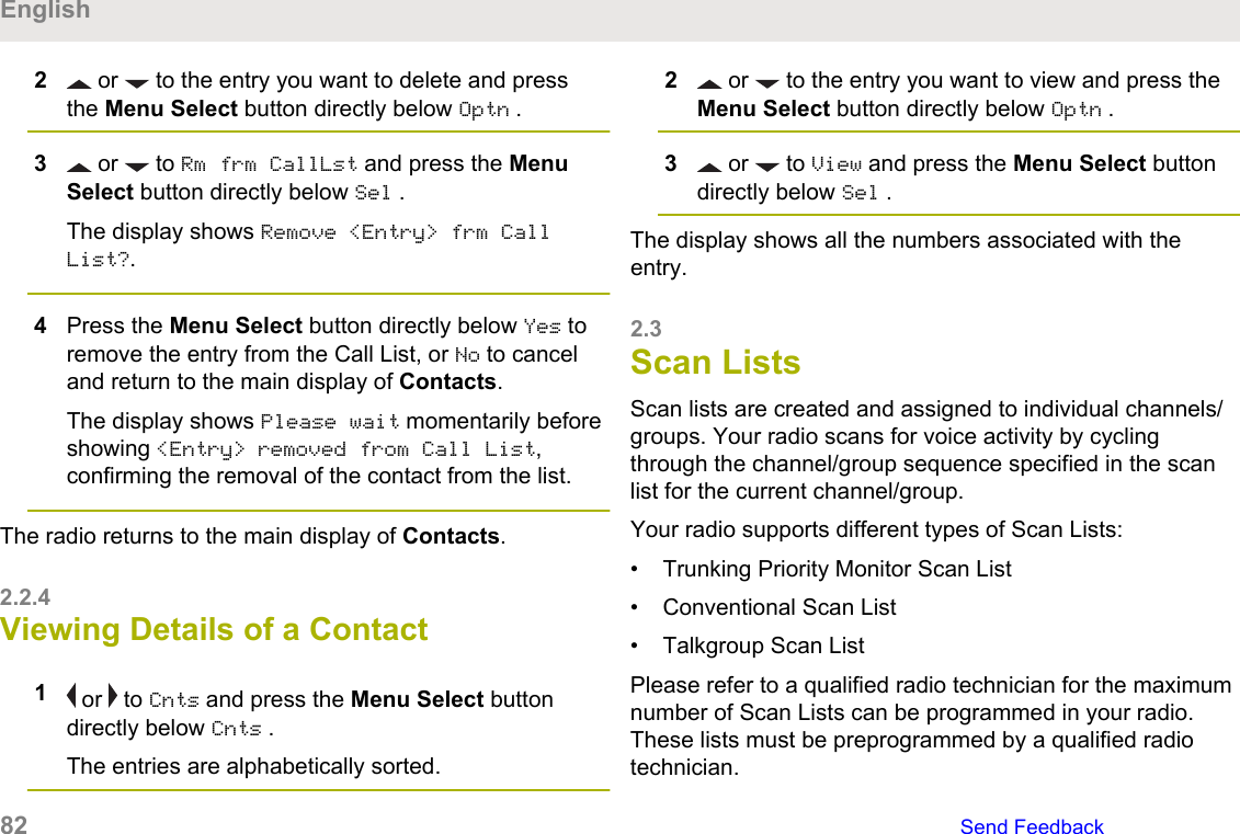
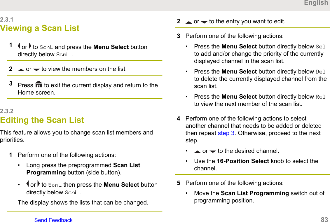
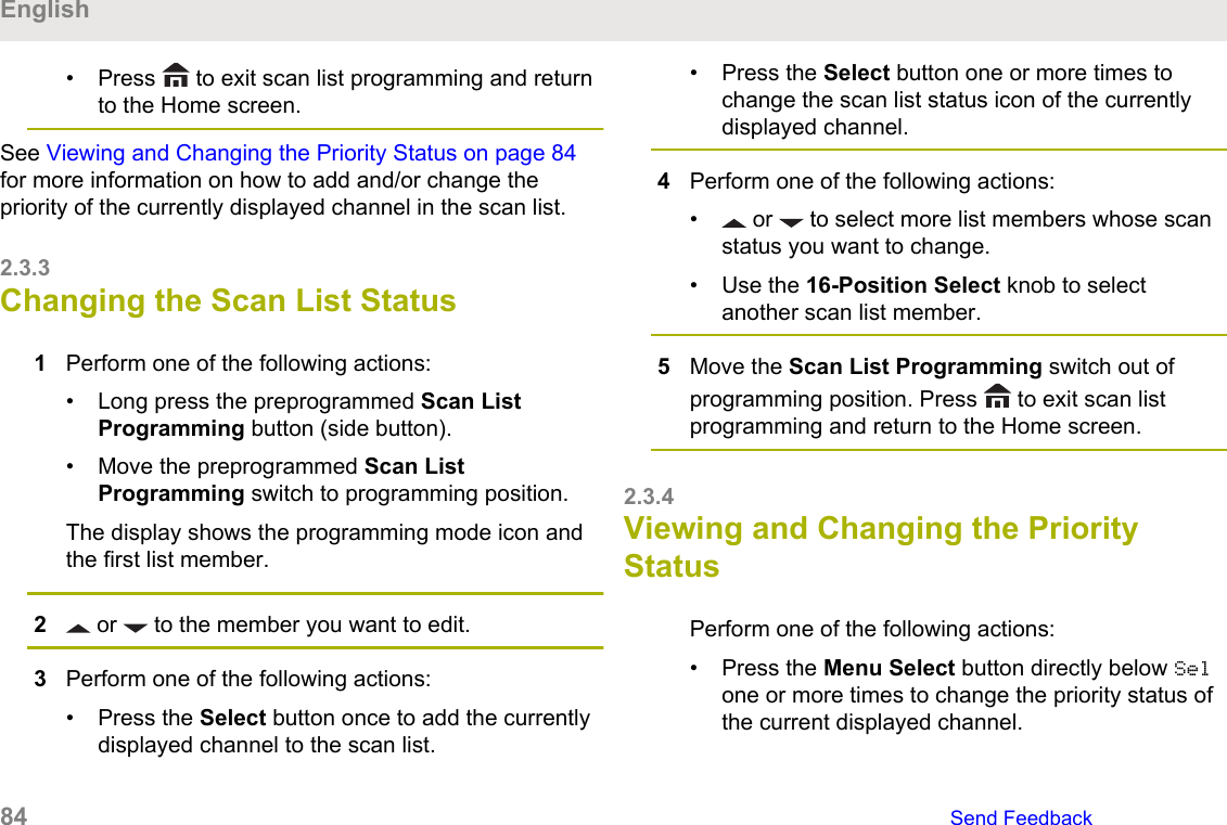
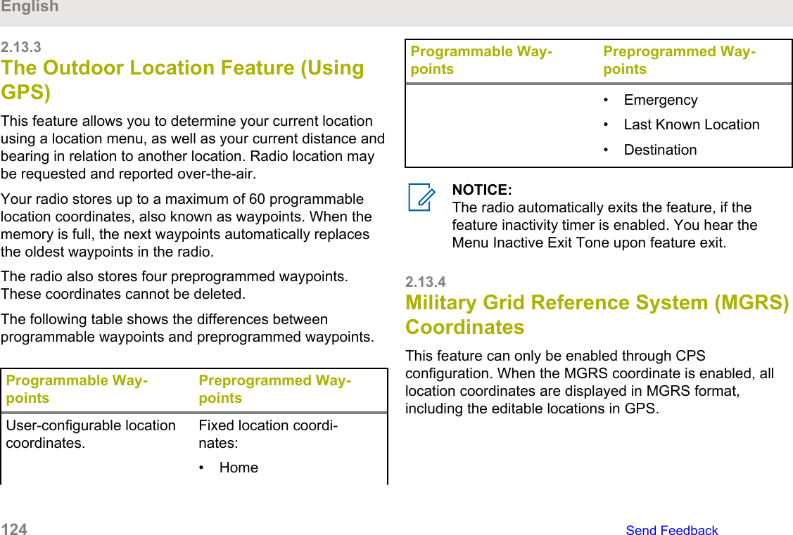
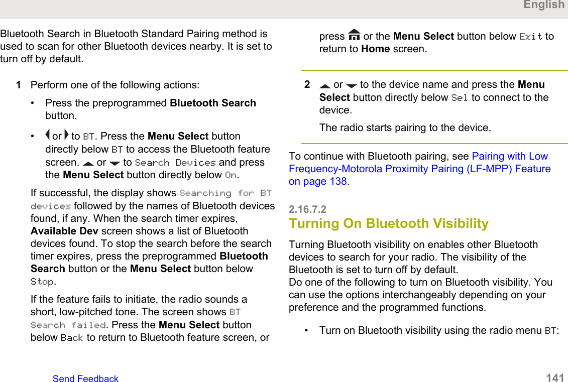
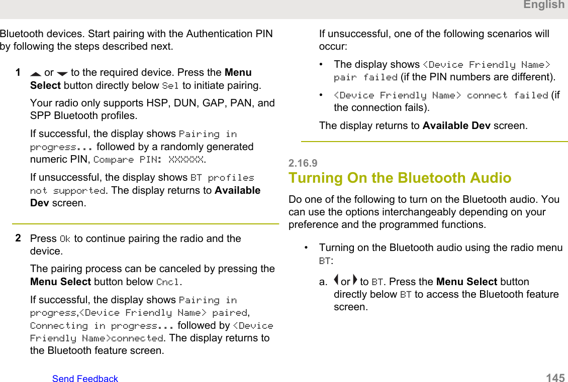
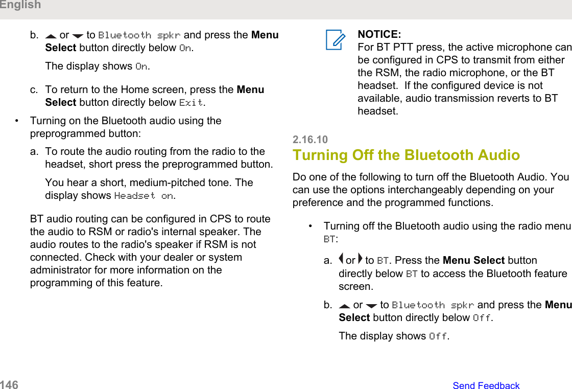
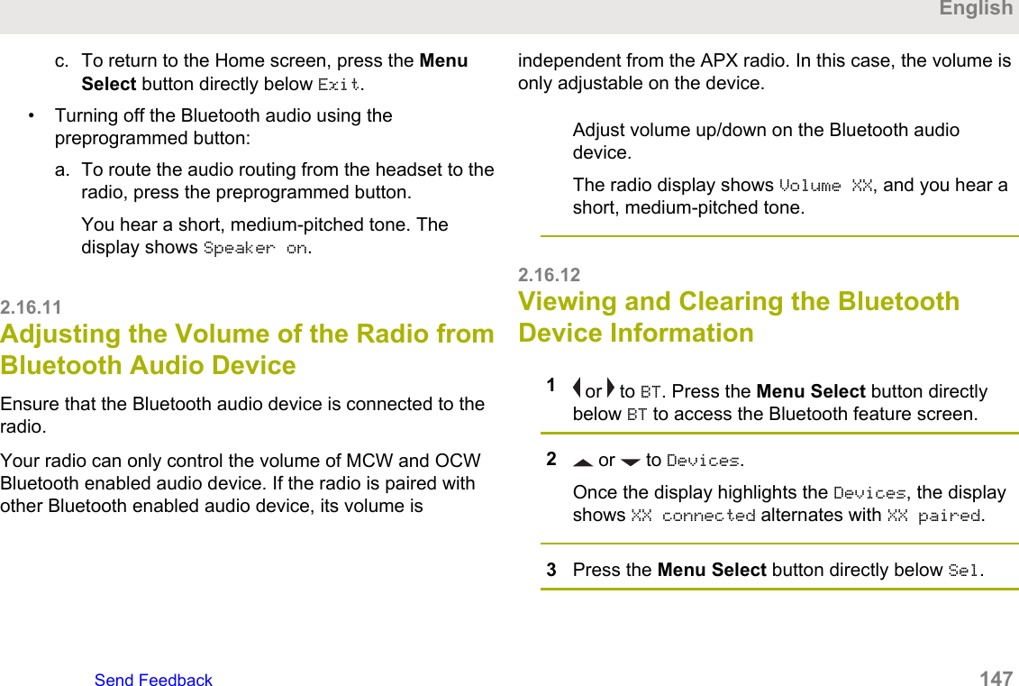
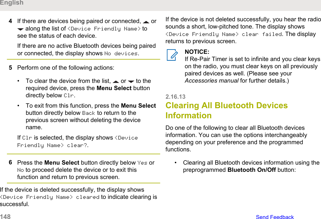
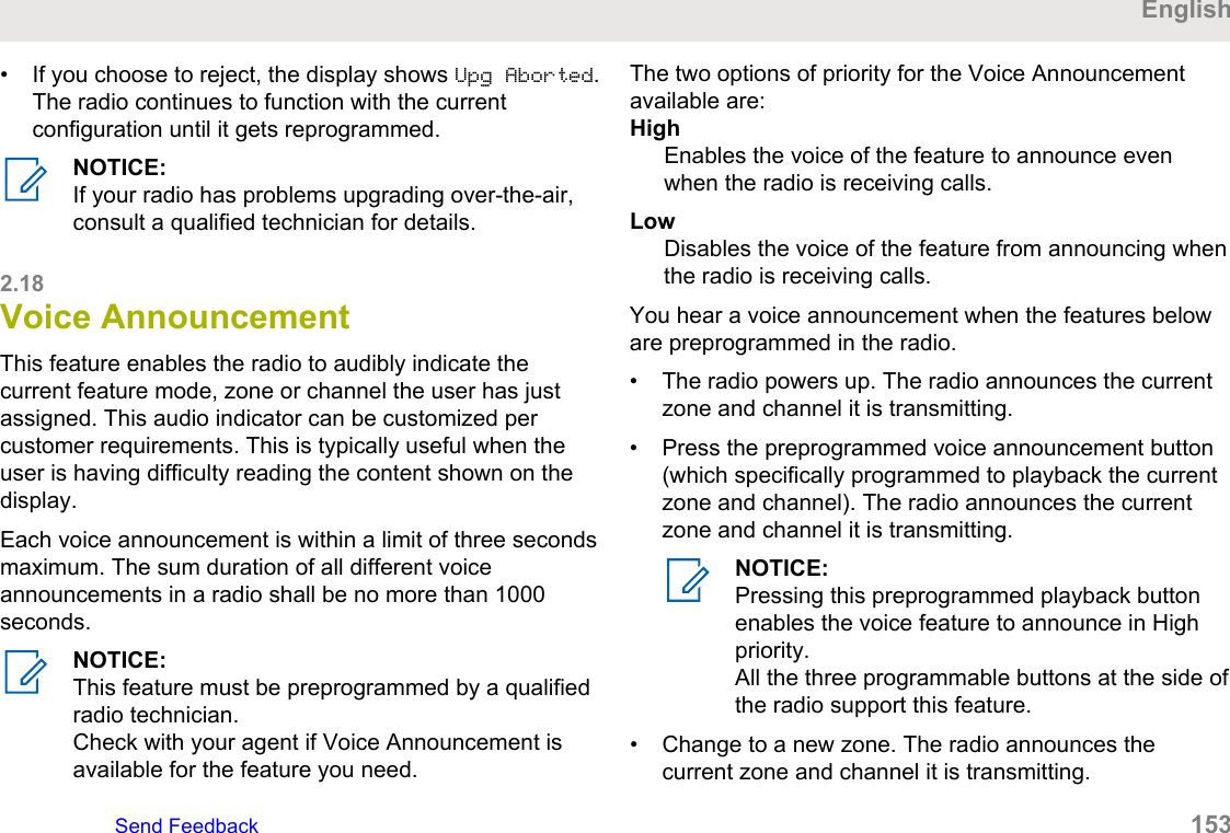
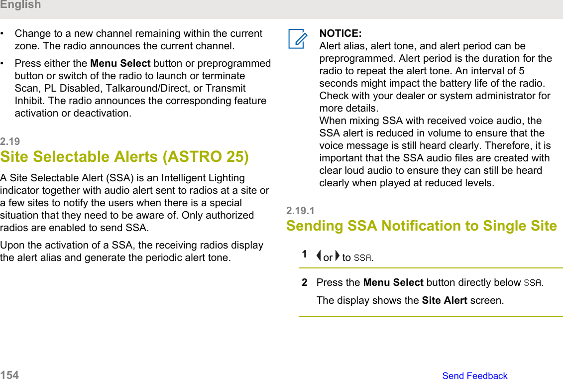
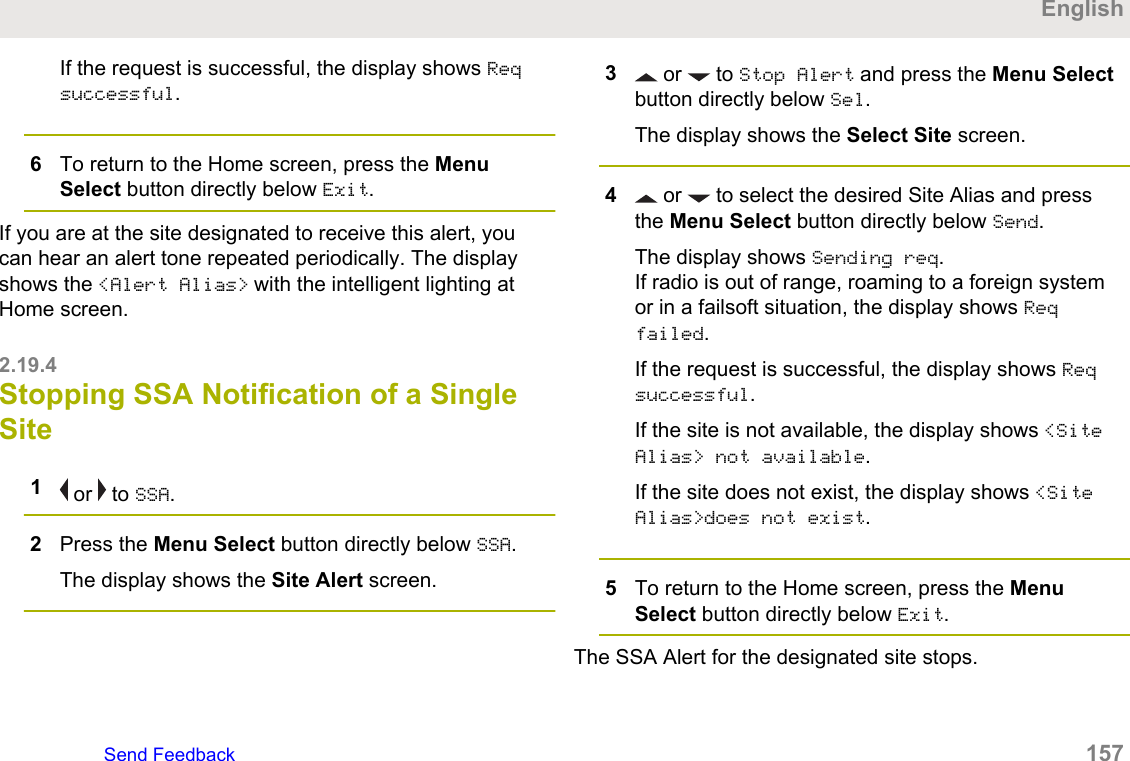
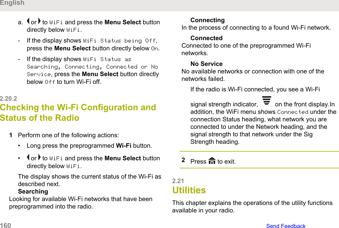
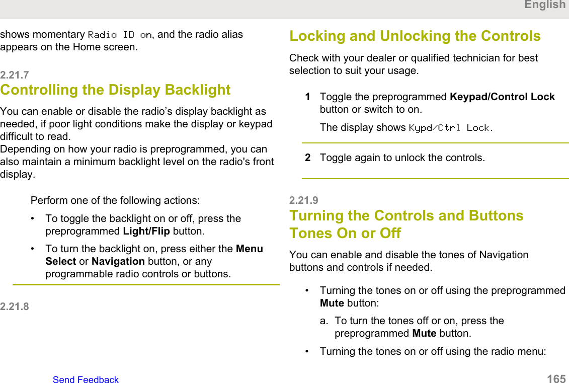
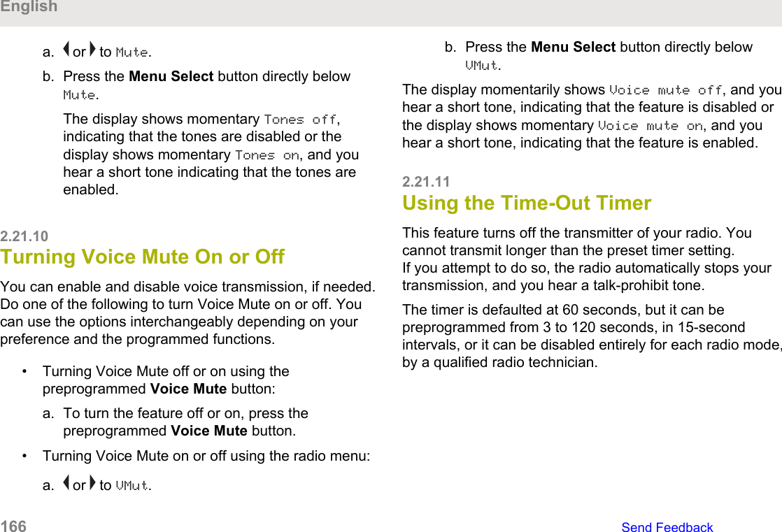
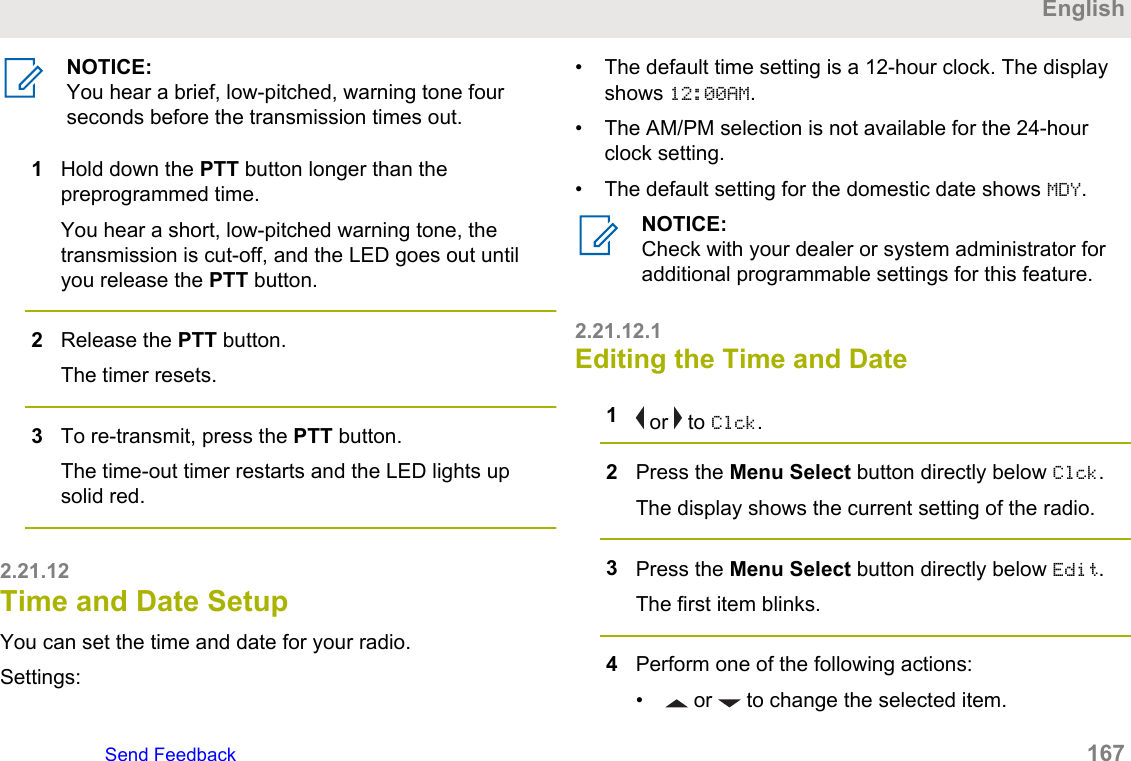
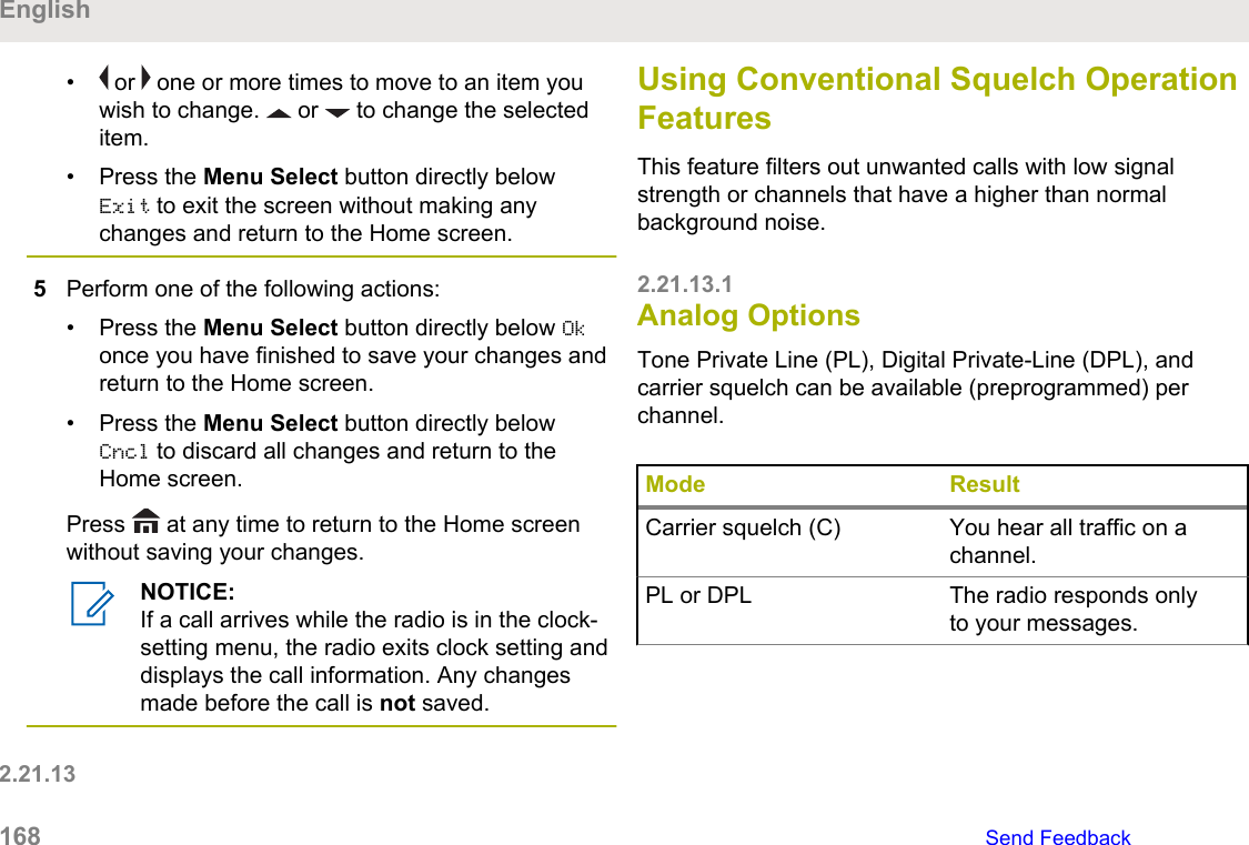
Motorola Solutions 89FT7111 2-Way Portable Radio with Bluetooth, Bluetooth LE and WiFi User Manual USER GUIDE
Motorola Solutions, Inc. 2-Way Portable Radio with Bluetooth, Bluetooth LE and WiFi USER GUIDE

Manual
APX TWO-WAY RADIOSAPX 8000HModel 2.5USER GUIDE*MN004476A01*MN004476A01-AAOCTOBER 2017© 2017 Motorola Solutions, Inc. All rights reserved
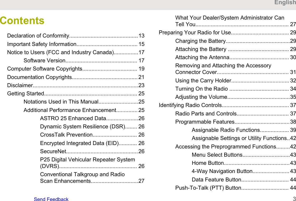
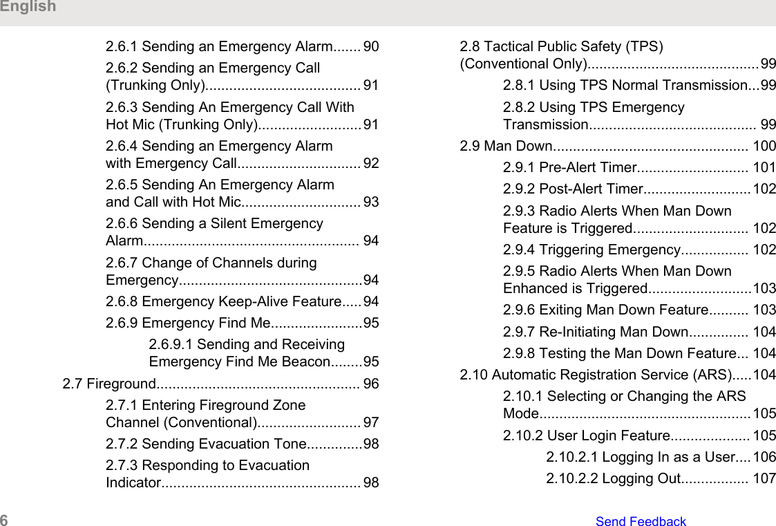
ContentsDeclaration of Conformity.............................................13Important Safety Information........................................ 15Notice to Users (FCC and Industry Canada)................17Software Version............................................... 17Computer Software Copyrights.................................... 19Documentation Copyrights........................................... 21Disclaimer.....................................................................23Getting Started............................................................. 25Notations Used in This Manual..........................25Additional Performance Enhancement.............. 25ASTRO 25 Enhanced Data.....................26Dynamic System Resilience (DSR)........ 26CrossTalk Prevention............................. 26Encrypted Integrated Data (EID)............ 26SecureNet...............................................26P25 Digital Vehicular Repeater System(DVRS)................................................... 26Conventional Talkgroup and RadioScan Enhancements...............................27What Your Dealer/System Administrator CanTell You............................................................. 27Preparing Your Radio for Use...................................... 29Charging the Battery..........................................29Attaching the Battery ........................................ 29Attaching the Antenna....................................... 30Removing and Attaching the AccessoryConnector Cover............................................... 31Using the Carry Holder...................................... 32Turning On the Radio ....................................... 34Adjusting the Volume.........................................35Identifying Radio Controls............................................ 37Radio Parts and Controls.................................. 37Programmable Features....................................38Assignable Radio Functions................... 39Assignable Settings or Utility Functions..42Accessing the Preprogrammed Functions.........42Menu Select Buttons...............................43Home Button...........................................434-Way Navigation Button........................ 43Data Feature Button............................... 44Push-To-Talk (PTT) Button............................... 44EnglishSend Feedback   3
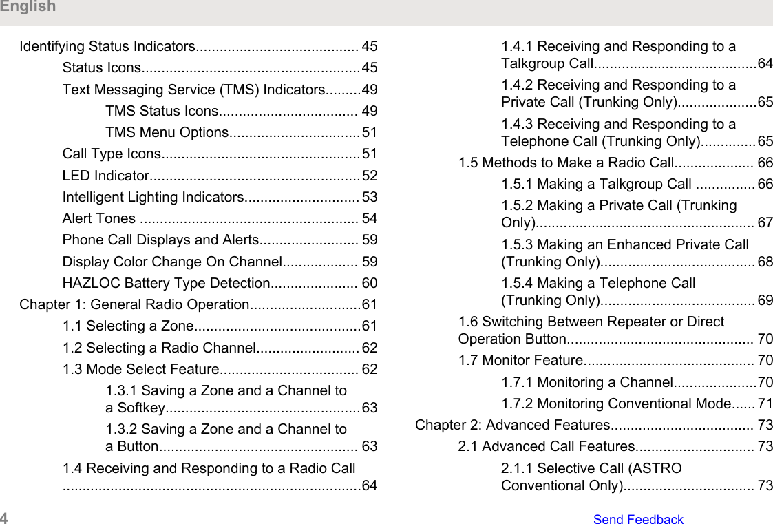
Identifying Status Indicators......................................... 45Status Icons.......................................................45Text Messaging Service (TMS) Indicators.........49TMS Status Icons................................... 49TMS Menu Options.................................51Call Type Icons..................................................51LED Indicator.....................................................52Intelligent Lighting Indicators............................. 53Alert Tones ....................................................... 54Phone Call Displays and Alerts......................... 59Display Color Change On Channel................... 59HAZLOC Battery Type Detection...................... 60Chapter 1: General Radio Operation............................611.1 Selecting a Zone..........................................611.2 Selecting a Radio Channel.......................... 621.3 Mode Select Feature................................... 621.3.1 Saving a Zone and a Channel toa Softkey.................................................631.3.2 Saving a Zone and a Channel toa Button.................................................. 631.4 Receiving and Responding to a Radio Call...........................................................................641.4.1 Receiving and Responding to aTalkgroup Call.........................................641.4.2 Receiving and Responding to aPrivate Call (Trunking Only)....................651.4.3 Receiving and Responding to aTelephone Call (Trunking Only)..............651.5 Methods to Make a Radio Call.................... 661.5.1 Making a Talkgroup Call ............... 661.5.2 Making a Private Call (TrunkingOnly)....................................................... 671.5.3 Making an Enhanced Private Call(Trunking Only)....................................... 681.5.4 Making a Telephone Call(Trunking Only)....................................... 691.6 Switching Between Repeater or DirectOperation Button............................................... 701.7 Monitor Feature........................................... 701.7.1 Monitoring a Channel.....................701.7.2 Monitoring Conventional Mode...... 71Chapter 2: Advanced Features.................................... 732.1 Advanced Call Features.............................. 732.1.1 Selective Call (ASTROConventional Only)................................. 73English4   Send Feedback
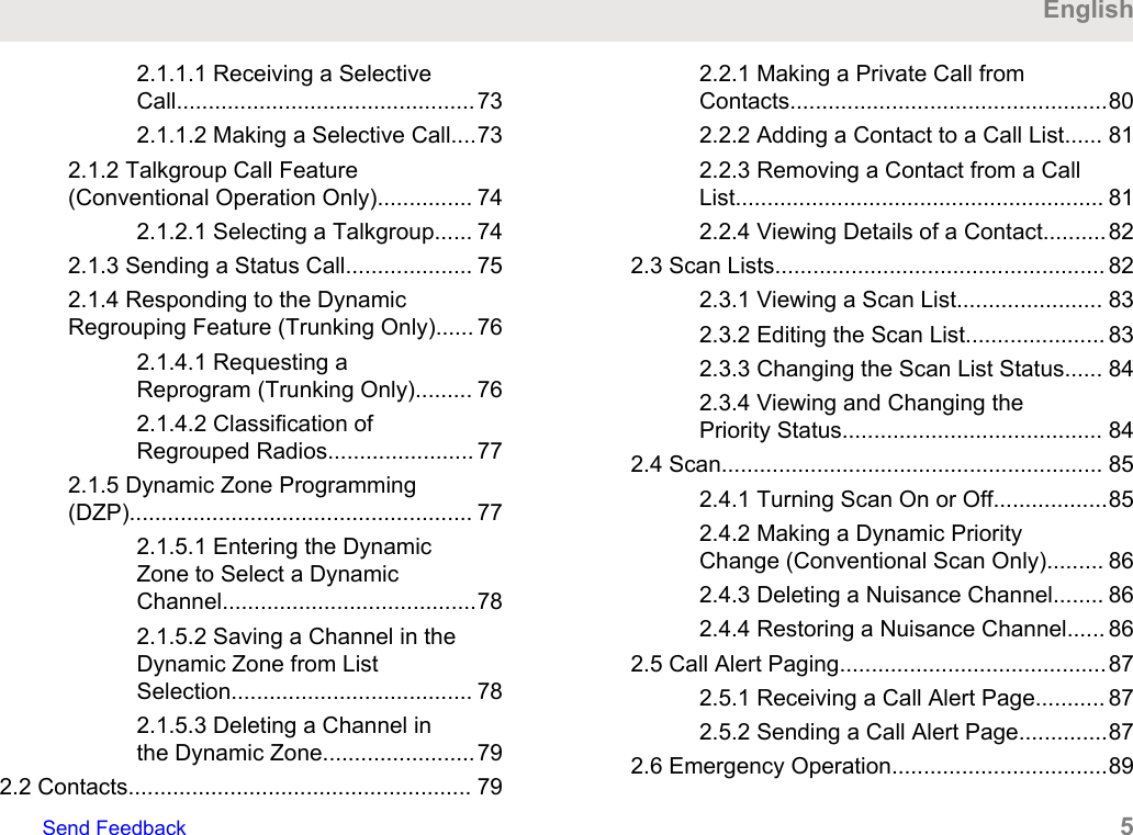
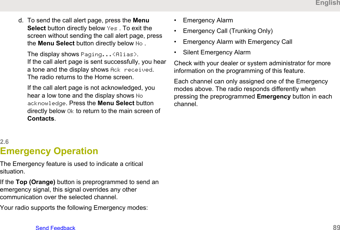
2.1.1.1 Receiving a SelectiveCall...............................................732.1.1.2 Making a Selective Call....732.1.2 Talkgroup Call Feature(Conventional Operation Only)............... 742.1.2.1 Selecting a Talkgroup...... 742.1.3 Sending a Status Call.................... 752.1.4 Responding to the DynamicRegrouping Feature (Trunking Only)...... 762.1.4.1 Requesting aReprogram (Trunking Only)......... 762.1.4.2 Classification ofRegrouped Radios....................... 772.1.5 Dynamic Zone Programming(DZP)...................................................... 772.1.5.1 Entering the DynamicZone to Select a DynamicChannel........................................782.1.5.2 Saving a Channel in theDynamic Zone from ListSelection...................................... 782.1.5.3 Deleting a Channel inthe Dynamic Zone........................792.2 Contacts...................................................... 792.2.1 Making a Private Call fromContacts..................................................802.2.2 Adding a Contact to a Call List...... 812.2.3 Removing a Contact from a CallList.......................................................... 812.2.4 Viewing Details of a Contact..........822.3 Scan Lists.................................................... 822.3.1 Viewing a Scan List....................... 832.3.2 Editing the Scan List...................... 832.3.3 Changing the Scan List Status...... 842.3.4 Viewing and Changing thePriority Status......................................... 842.4 Scan............................................................ 852.4.1 Turning Scan On or Off..................852.4.2 Making a Dynamic PriorityChange (Conventional Scan Only)......... 862.4.3 Deleting a Nuisance Channel........ 862.4.4 Restoring a Nuisance Channel...... 862.5 Call Alert Paging..........................................872.5.1 Receiving a Call Alert Page........... 872.5.2 Sending a Call Alert Page..............872.6 Emergency Operation..................................89EnglishSend Feedback   5
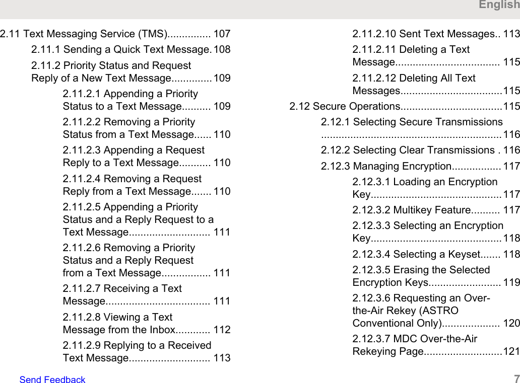
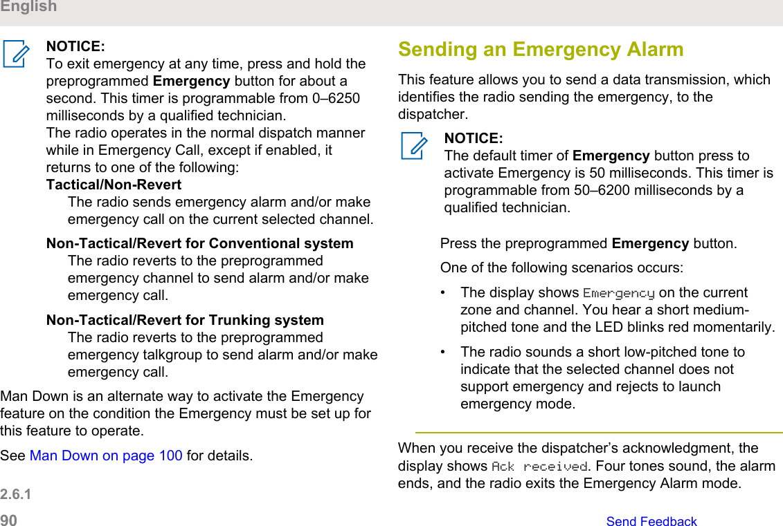
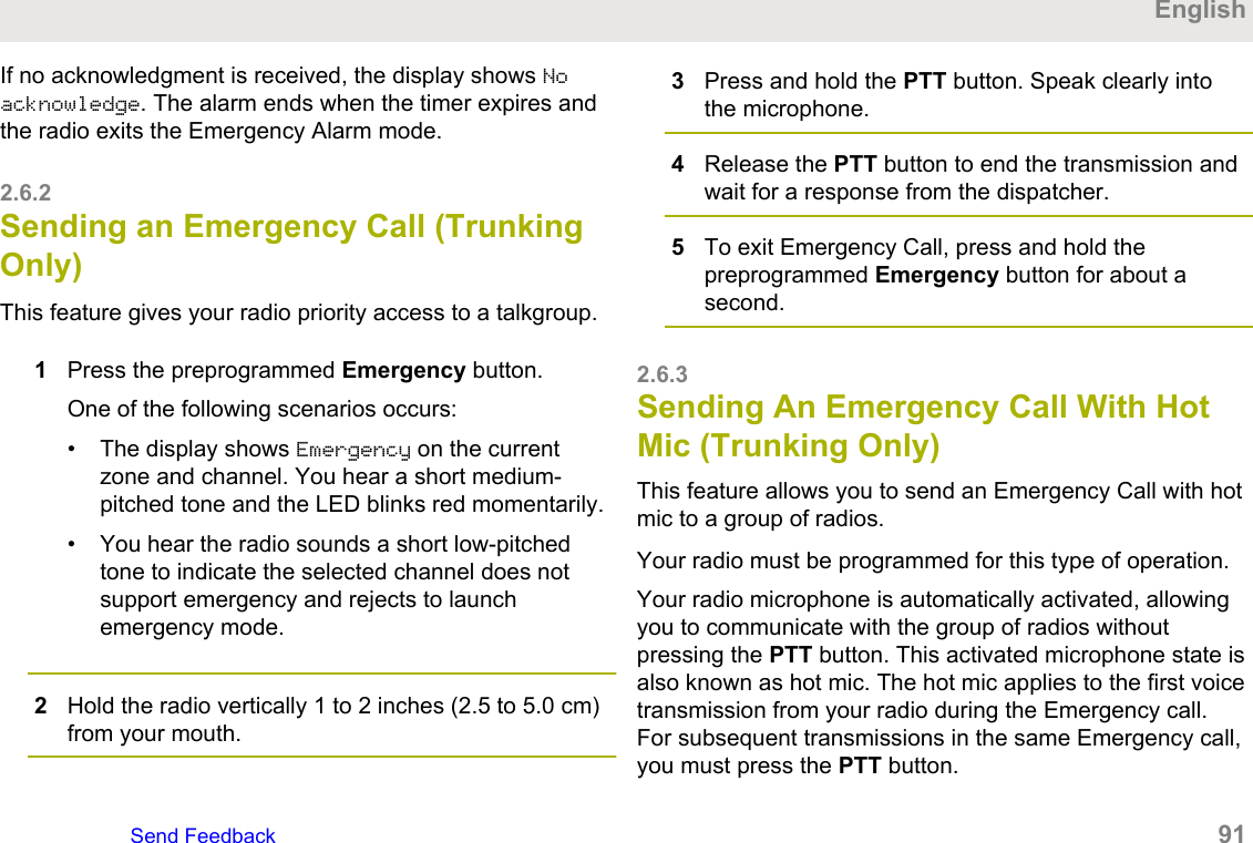
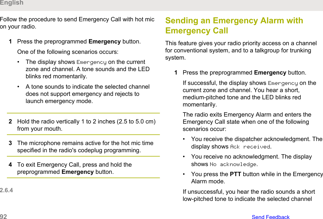
2.6.1 Sending an Emergency Alarm....... 902.6.2 Sending an Emergency Call(Trunking Only)....................................... 912.6.3 Sending An Emergency Call WithHot Mic (Trunking Only)..........................912.6.4 Sending an Emergency Alarmwith Emergency Call............................... 922.6.5 Sending An Emergency Alarmand Call with Hot Mic.............................. 932.6.6 Sending a Silent EmergencyAlarm...................................................... 942.6.7 Change of Channels duringEmergency..............................................942.6.8 Emergency Keep-Alive Feature.....942.6.9 Emergency Find Me.......................952.6.9.1 Sending and ReceivingEmergency Find Me Beacon........952.7 Fireground................................................... 962.7.1 Entering Fireground ZoneChannel (Conventional).......................... 972.7.2 Sending Evacuation Tone..............982.7.3 Responding to EvacuationIndicator.................................................. 982.8 Tactical Public Safety (TPS)(Conventional Only)...........................................992.8.1 Using TPS Normal Transmission...992.8.2 Using TPS EmergencyTransmission.......................................... 992.9 Man Down................................................. 1002.9.1 Pre-Alert Timer............................ 1012.9.2 Post-Alert Timer...........................1022.9.3 Radio Alerts When Man DownFeature is Triggered............................. 1022.9.4 Triggering Emergency................. 1022.9.5 Radio Alerts When Man DownEnhanced is Triggered..........................1032.9.6 Exiting Man Down Feature.......... 1032.9.7 Re-Initiating Man Down............... 1042.9.8 Testing the Man Down Feature... 1042.10 Automatic Registration Service (ARS).....1042.10.1 Selecting or Changing the ARSMode.....................................................1052.10.2 User Login Feature.................... 1052.10.2.1 Logging In as a User....1062.10.2.2 Logging Out................. 107English6   Send Feedback
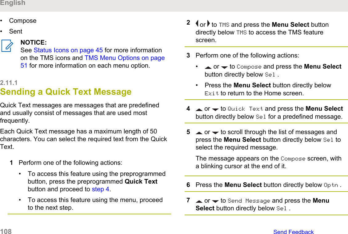
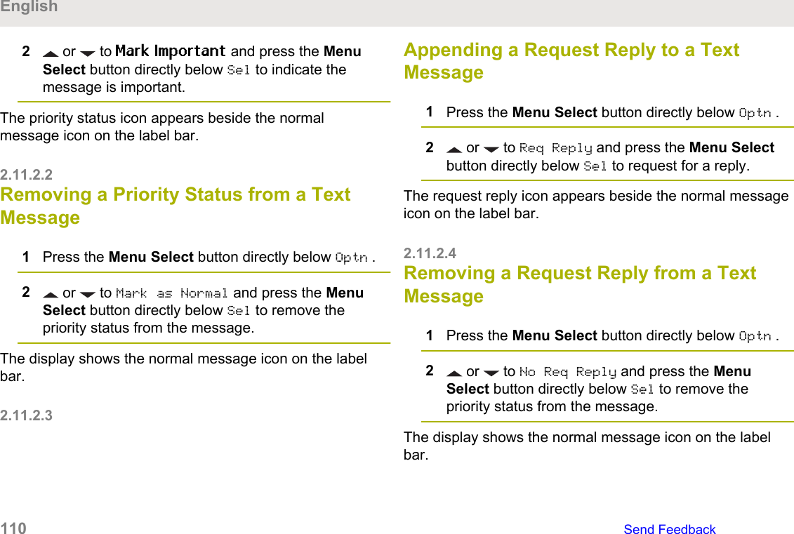
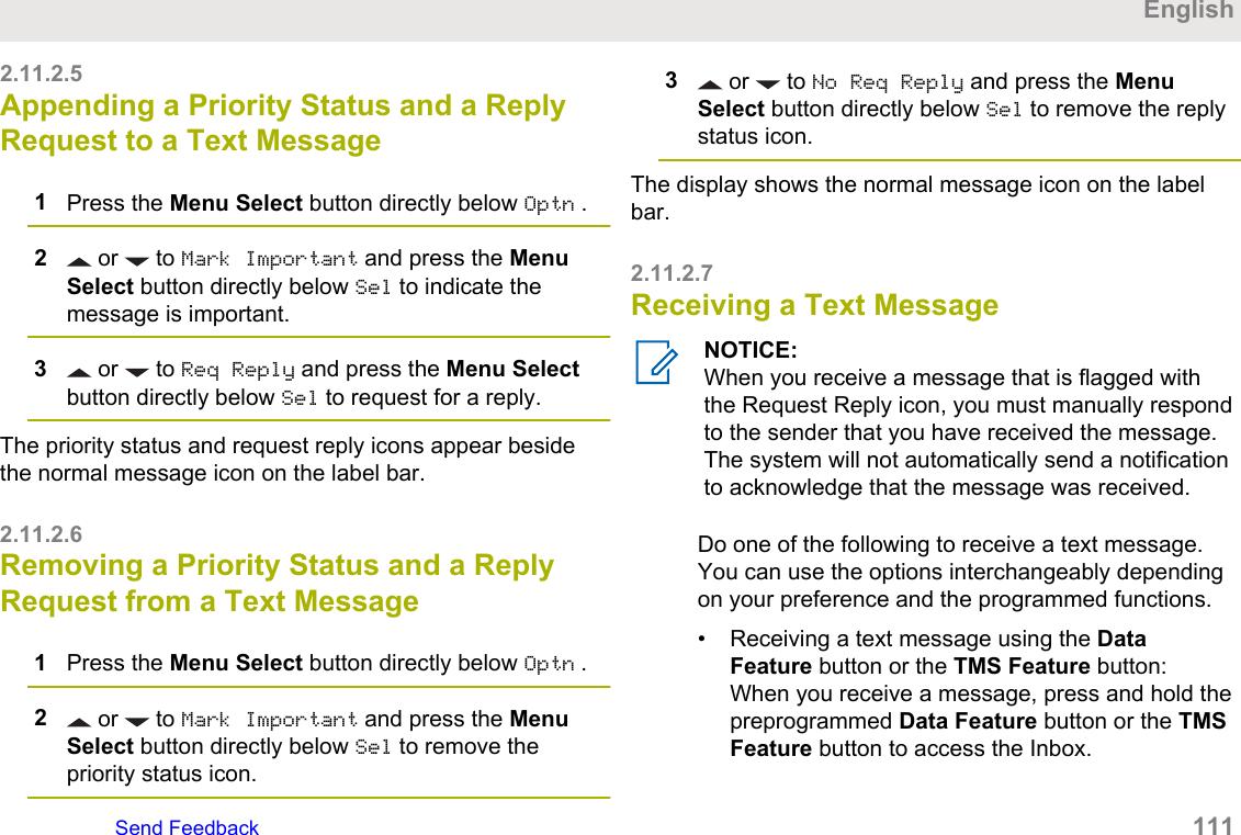
2.11 Text Messaging Service (TMS)............... 1072.11.1 Sending a Quick Text Message.1082.11.2 Priority Status and RequestReply of a New Text Message..............1092.11.2.1 Appending a PriorityStatus to a Text Message.......... 1092.11.2.2 Removing a PriorityStatus from a Text Message...... 1102.11.2.3 Appending a RequestReply to a Text Message........... 1102.11.2.4 Removing a RequestReply from a Text Message....... 1102.11.2.5 Appending a PriorityStatus and a Reply Request to aText Message............................ 1112.11.2.6 Removing a PriorityStatus and a Reply Requestfrom a Text Message................. 1112.11.2.7 Receiving a TextMessage.................................... 1112.11.2.8 Viewing a TextMessage from the Inbox............ 1122.11.2.9 Replying to a ReceivedText Message............................ 1132.11.2.10 Sent Text Messages.. 1132.11.2.11 Deleting a TextMessage.................................... 1152.11.2.12 Deleting All TextMessages...................................1152.12 Secure Operations...................................1152.12.1 Selecting Secure Transmissions..............................................................1162.12.2 Selecting Clear Transmissions . 1162.12.3 Managing Encryption................. 1172.12.3.1 Loading an EncryptionKey.............................................1172.12.3.2 Multikey Feature.......... 1172.12.3.3 Selecting an EncryptionKey.............................................1182.12.3.4 Selecting a Keyset....... 1182.12.3.5 Erasing the SelectedEncryption Keys......................... 1192.12.3.6 Requesting an Over-the-Air Rekey (ASTROConventional Only).................... 1202.12.3.7 MDC Over-the-AirRekeying Page...........................121EnglishSend Feedback   7
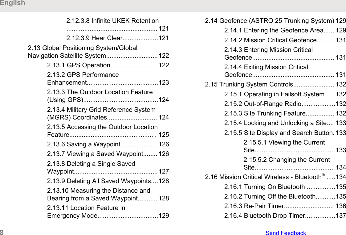
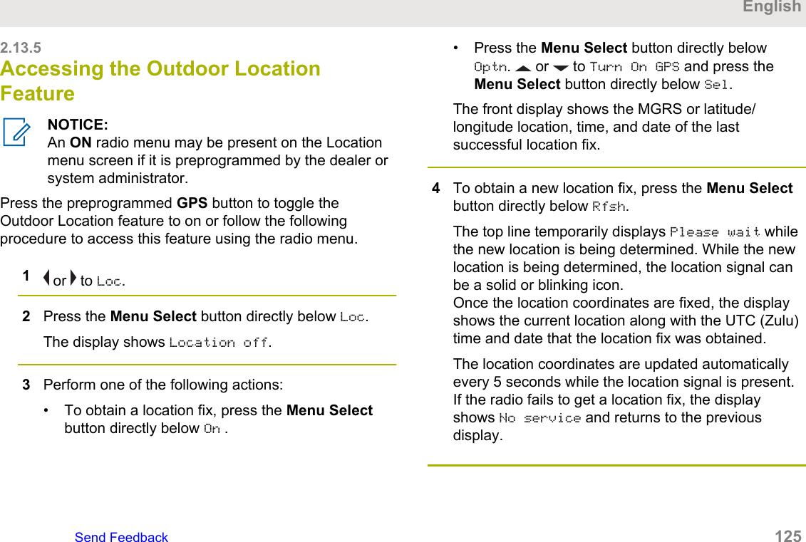
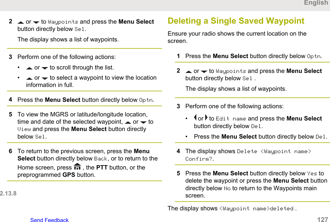
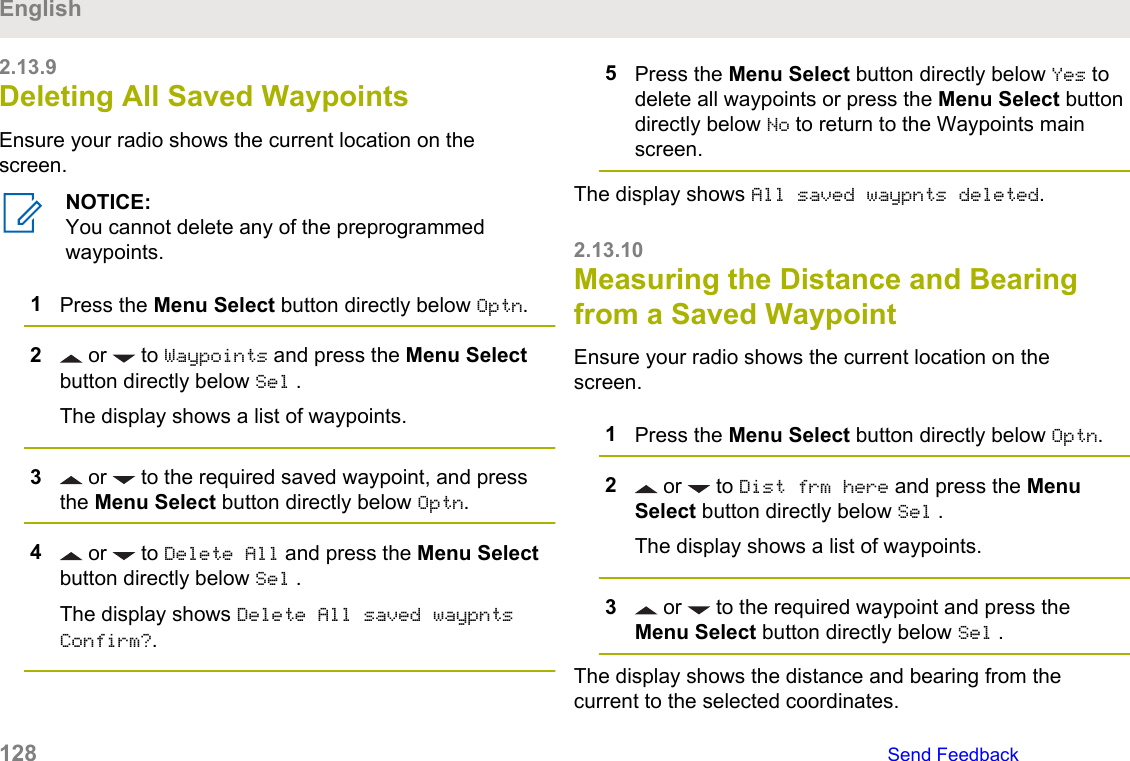
2.12.3.8 Infinite UKEK Retention................................................... 1212.12.3.9 Hear Clear....................1212.13 Global Positioning System/GlobalNavigation Satellite System.............................1222.13.1 GPS Operation.......................... 1222.13.2 GPS PerformanceEnhancement........................................1232.13.3 The Outdoor Location Feature(Using GPS)..........................................1242.13.4 Military Grid Reference System(MGRS) Coordinates............................ 1242.13.5 Accessing the Outdoor LocationFeature................................................. 1252.13.6 Saving a Waypoint.....................1262.13.7 Viewing a Saved Waypoint........ 1262.13.8 Deleting a Single SavedWaypoint...............................................1272.13.9 Deleting All Saved Waypoints....1282.13.10 Measuring the Distance andBearing from a Saved Waypoint........... 1282.13.11 Location Feature inEmergency Mode..................................1292.14 Geofence (ASTRO 25 Trunking System) 1292.14.1 Entering the Geofence Area...... 1292.14.2 Mission Critical Geofence.......... 1312.14.3 Entering Mission CriticalGeofence.............................................. 1312.14.4 Exiting Mission CriticalGeofence.............................................. 1312.15 Trunking System Controls....................... 1322.15.1 Operating in Failsoft System......1322.15.2 Out-of-Range Radio...................1322.15.3 Site Trunking Feature................ 1322.15.4 Locking and Unlocking a Site.... 1332.15.5 Site Display and Search Button. 1332.15.5.1 Viewing the CurrentSite.............................................1332.15.5.2 Changing the CurrentSite.............................................1342.16 Mission Critical Wireless - Bluetooth® .....1342.16.1 Turning On Bluetooth ................1352.16.2 Turning Off the Bluetooth...........1352.16.3 Re-Pair Timer............................ 1362.16.4 Bluetooth Drop Timer.................137English8   Send Feedback
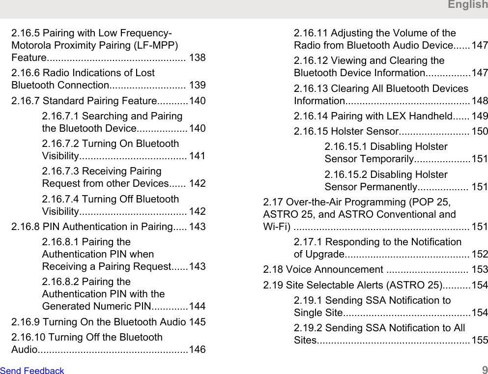
2.16.5 Pairing with Low Frequency-Motorola Proximity Pairing (LF-MPP)Feature................................................. 1382.16.6 Radio Indications of LostBluetooth Connection........................... 1392.16.7 Standard Pairing Feature...........1402.16.7.1 Searching and Pairingthe Bluetooth Device..................1402.16.7.2 Turning On BluetoothVisibility...................................... 1412.16.7.3 Receiving PairingRequest from other Devices...... 1422.16.7.4 Turning Off BluetoothVisibility...................................... 1422.16.8 PIN Authentication in Pairing..... 1432.16.8.1 Pairing theAuthentication PIN whenReceiving a Pairing Request......1432.16.8.2 Pairing theAuthentication PIN with theGenerated Numeric PIN.............1442.16.9 Turning On the Bluetooth Audio 1452.16.10 Turning Off the BluetoothAudio.....................................................1462.16.11 Adjusting the Volume of theRadio from Bluetooth Audio Device......1472.16.12 Viewing and Clearing theBluetooth Device Information................1472.16.13 Clearing All Bluetooth DevicesInformation............................................1482.16.14 Pairing with LEX Handheld...... 1492.16.15 Holster Sensor......................... 1502.16.15.1 Disabling HolsterSensor Temporarily....................1512.16.15.2 Disabling HolsterSensor Permanently.................. 1512.17 Over-the-Air Programming (POP 25,ASTRO 25, and ASTRO Conventional andWi-Fi) .............................................................. 1512.17.1 Responding to the Notificationof Upgrade............................................ 1522.18 Voice Announcement ............................. 1532.19 Site Selectable Alerts (ASTRO 25)..........1542.19.1 Sending SSA Notification toSingle Site.............................................1542.19.2 Sending SSA Notification to AllSites......................................................155EnglishSend Feedback   9
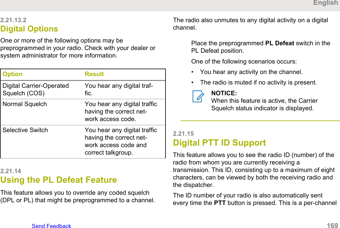
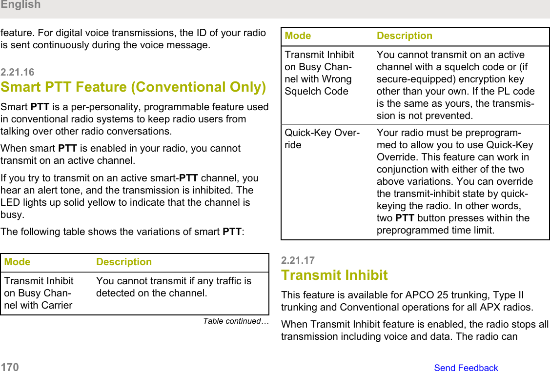
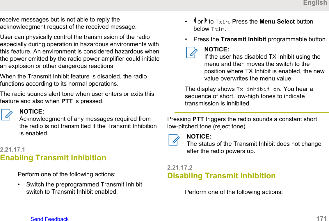
2.19.3 Sending SSA Notification to AllAvailable Sites...................................... 1562.19.4 Stopping SSA Notification of aSingle Site.............................................1572.19.5 Stopping SSA Notification of AllSites......................................................1582.19.6 Stopping SSA Notification of AllAvailable Sites...................................... 1582.20 Wi-Fi........................................................ 1592.20.1 Turning Wi-Fi On or Off............. 1592.20.2 Checking the Wi-FiConfiguration and Status of the Radio..1602.21 Utilities..................................................... 1602.21.1 Viewing Recent Calls.................1612.21.2 Using the Flip Display................ 1612.21.3 Selecting a Basic Zone Bank.....1622.21.4 Selecting the Power Level......... 1622.21.5 Selecting a Radio Profile........... 1632.21.5.1 Selecting an EnhancedZone Bank..................................1642.21.6 Enabling and Disabling theRadio Alias............................................1642.21.7 Controlling the Display Backlight..............................................................1652.21.8 Locking and Unlocking theControls................................................ 1652.21.9 Turning the Controls andButtons Tones On or Off.......................1652.21.10 Turning Voice Mute On or Off..1662.21.11 Using the Time-Out Timer....... 1662.21.12 Time and Date Setup...............1672.21.12.1 Editing the Time andDate........................................... 1672.21.13 Using Conventional SquelchOperation Features...............................1682.21.13.1 Analog Options.......... 1682.21.13.2 Digital Options............1692.21.14 Using the PL Defeat Feature... 1692.21.15 Digital PTT ID Support.............1692.21.16 Smart PTT Feature(Conventional Only).............................. 1702.21.17 Transmit Inhibit........................ 1702.21.17.1 Enabling TransmitInhibition.....................................171English10   Send Feedback
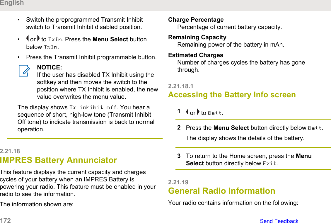
2.21.17.2 Disabling TransmitInhibition.....................................1712.21.18 IMPRES Battery Annunciator.. 1722.21.18.1 Accessing the BatteryInfo screen................................. 1722.21.19 General Radio Information.......1722.21.19.1 Accessing the RadioInformation................................. 1732.21.19.2 Viewing the IPInformation................................. 1742.21.19.3 Viewing the ControlAssignments.............................. 175Chapter 3: Helpful Tips...............................................1773.1 Radio Care................................................ 1773.1.1 Cleaning Your Radio....................1783.1.2 Proper Ways to Handle the Radio..............................................................1793.1.3 Radio Service and Repair............1793.2 Battery Care.............................................. 1793.2.1 Battery Charge Status................. 1793.2.1.1 LED and Sounds............1803.2.1.2 Fuel Gauge Icons...........1803.2.2 Battery Recycling and Disposal... 181Chapter 4: Accessories.............................................. 183Chapter 5: Maritime Radio Use in the VHFFrequency Range.......................................................1855.1 Special Channel Assignments...................1855.1.1 Emergency Channel.................... 1855.1.2 Non-Commercial Call Channel.... 1865.2 Operating Frequency Requirements......... 1865.3 Declaration of Compliance for the Use ofDistress and Safety Frequencies.....................1885.4 Technical Parameters for InterfacingExternal Data Sources.....................................189Chapter 6: Glossary................................................... 191Chapter 7: Limited Warranty...................................... 1997.1 MOTOROLA SOLUTIONSCOMMUNICATION PRODUCTS.................... 1997.2 I. WHAT THIS WARRANTY COVERSAND FOR HOW LONG:.................................. 1997.3 II. GENERAL PROVISIONS:..................... 2007.4 III. STATE LAW RIGHTS:..........................2017.5 IV. HOW TO GET WARRANTYSERVICE:........................................................2017.6 V. WHAT THIS WARRANTY DOES NOTCOVER:...........................................................201EnglishSend Feedback   11
7.7 VI. PATENT AND SOFTWAREPROVISIONS:................................................. 2027.8 VII. GOVERNING LAW:............................ 2037.9 VIII. For Australia Only.............................. 204English12   Send Feedback
Declaration of ConformityThis declaration is applicable to your radio only if your radio is labeled with the FCC logo shown below.Declaration of ConformityPer FCC CFR 47 Part 2 Section 2.1077(a)Responsible PartyName: Motorola Solutions, Inc.Address: 1303 East Algonquin Road, Schaumburg, IL 60196-1078, U.S.A.Phone Number: 1-800-927-2744Hereby declares that the product:Model Name: APX 8000Hconforms to the following regulations:FCC Part 15, subpart B, section 15.107(a), 15.107(d), and section 15.109(a)Table continued…EnglishSend Feedback   13
Class B Digital DeviceAs a personal computer peripheral, this device complies with Part 15 of the FCC Rules. This device complies withIndustry Canada license-exempt RSS standard(s). Operation is subject to the following two conditions:1This device may not cause harmful interference, and2This device must accept any interference received, including interference that may cause undesired operation.NOTICE:This equipment has been tested and found to comply with the limits for a Class B digital device, pursuant topart 15 of the FCC Rules and Industry Canada license-exempt RSS standard. These limits are designed toprovide reasonable protection against harmful interference in a residential installation. This equipment gen-erates, uses and can radiate radio frequency energy and, if not installed and used in accordance with theinstructions, may cause harmful interference to radio communications. However, there is no guarantee thatinterference will not occur in a particular installation.If this equipment does cause harmful interference to radio or television reception, which can be determinedby turning the equipment off and on, the user is encouraged to try to correct the interference by one or moreof the following measures:• Reorient or relocate the receiving antenna.• Increase the separation between the equipment and receiver.• Connect the equipment into an outlet on a circuit different from that to which the receiver is connected.• Consult the dealer or an experienced radio or TV technician for help.English14   Send Feedback
Important Safety InformationRF Energy Exposure and Product SafetyGuide for Portable Two-Way RadiosATTENTION!This radio is restricted to Occupational use only. Beforeusing the radio, read the RF Energy Exposure and ProductSafety Guide for Portable Two-Way Radios which containsimportant operating instructions for safe usage and RFenergy awareness and control for Compliance withapplicable standards and Regulations.For a list of Motorola Solutions-approved antennas,batteries, and other accessories, visit the following website:http://www.motorolasolutions.comUnder Industry Canada regulations, this radio transmittermay only operate using an antenna of a type and maximum(or lesser) gain approved for the transmitter by IndustryCanada. To reduce potential radio interference to otherusers, the antenna type and its gain should be so chosenthat the equivalent isotropically radiated power (e.i.r.p.) isnot more than that necessary for successfulcommunication.This radio transmitter has been approved by IndustryCanada to operate with Motorola Solutions-approvedantenna with the maximum permissible gain and requiredantenna impedance for each antenna type indicated.Antenna types not included in this list, having a gaingreater than the maximum gain indicated for that type, arestrictly prohibited for use with this device.EnglishSend Feedback   15
EnglishThis page intentionally left blank.16
Notice to Users (FCC andIndustry Canada)This device complies with Part 15 of the FCC rules andIndustry Canada's license-exempt RSS's per the followingconditions:• This device may not cause harmful interference.• This device must accept any interference received,including interference that may cause undesiredoperation.• Changes or modifications made to this device, notexpressly approved by Motorola Solutions, could voidthe authority of the user to operate this equipment.Software VersionAll the features described in the following sections aresupported by the software version R16.00.00 or later.See Accessing the Radio Information on page 173 todetermine the software version of your radio.Check with your dealer or system administrator for moredetails of all the features supported.EnglishSend Feedback   17
EnglishThis page intentionally left blank.18
Computer SoftwareCopyrightsThe Motorola Solutions products described in this manualmay include copyrighted Motorola Solutions computerprograms stored in semiconductor memories or othermedia. Laws in the United States and other countriespreserve for Motorola Solutions certain exclusive rights forcopyrighted computer programs including, but not limitedto, the exclusive right to copy or reproduce in any form thecopyrighted computer program. Accordingly, anycopyrighted Motorola Solutions computer programscontained in the Motorola Solutions products described inthis manual may not be copied, reproduced, modified,reverse-engineered, or distributed in any manner withoutthe express written permission of Motorola Solutions.Furthermore, the purchase of Motorola Solutions productsshall not be deemed to grant either directly or byimplication, estoppel, or otherwise, any license under thecopyrights, patents or patent applications of MotorolaSolutions, except for the normal non-exclusive license touse that arises by operation of law in the sale of a product.EnglishSend Feedback   19
EnglishThis page intentionally left blank.20
Documentation CopyrightsNo duplication or distribution of this document or anyportion thereof shall take place without the express writtenpermission of Motorola Solutions. No part of this manualmay be reproduced, distributed, or transmitted in any formor by any means, electronic or mechanical, for any purposewithout the express written permission of MotorolaSolutions.EnglishSend Feedback   21
EnglishThis page intentionally left blank.22
DisclaimerThe information in this document is carefully examined, andis believed to be entirely reliable. However, noresponsibility is assumed for inaccuracies. Furthermore,Motorola Solutions reserves the right to make changes toany products herein to improve readability, function, ordesign. Motorola Solutions does not assume any liabilityarising out of the applications or use of any product orcircuit described herein; nor does it cover any license underits patent rights, nor the rights of others.EnglishSend Feedback   23
EnglishThis page intentionally left blank.24
Getting StartedHow to Use This GuideThis User Guide covers the basic operation of the APXPortables .However, your dealer or system administrator may havecustomized your radio for your specific needs. Check withyour dealer or system administrator for more information.Notations Used in This ManualThroughout the text in this publication, you will notice theuse of Warning, Caution, and Notice. These notations areused to emphasize that safety hazards exist, and the carethat must be taken or observed.WARNING:An operational procedure, practice, or condition andso on, which may result in injury or death if notcarefully observed.CAUTION:An operational procedure, practice, or condition andso on, which may result in damage to the equipmentif not carefully observed.NOTICE:An operational procedure, practice, or condition andso on, which is essential to emphasize.The following special notations identify certain items.Example DescriptionHome buttonor Buttons and keys are shown in boldprint or as an icon.Phon Menu entries are shown similar tothe way they appear on the displayof the radio.This means “Press the right side ofthe 4-Way Navigation Button”.Additional PerformanceEnhancementThe following performance enhancements are some of thelatest creations designed to enhance the security, quality,and efficiency of the radios.EnglishSend Feedback   25
ASTRO 25 Enhanced DataASTRO 25 Enhanced Data is optimized to handle differentmessage sizes and variable update rates from differentapplications of the radio. Add Enhanced Data to theIntegrated Data system with a software installation toimprove data channel efficiency and enable denser networktraffic.Dynamic System Resilience (DSR)DSR ensures the radio system is seamlessly switched to abackup master site dynamically in case of system failure.DSR also provides additional indication such as failuredetection, fault recovery, and redundancy within the systemto address to the user in need. Mechanisms related to theIntegrated Voice and Data (IV&D) or data centric are allsupported by DSR.CrossTalk PreventionThis feature prevents crosstalk scenarios from happening,especially when a wideband antenna is used. This featureallows the adjustment of the internal SSI clock rate of theradio. This subsequently reduces the possibility of radiofrequency interfering spurs and prevents the issues ofcrosstalk.Encrypted Integrated Data (EID)EID provides security encryption and authentication ofIV&D data bearer service communication between theradio and the Customer Enterprise Network.SecureNetSecureNet allows user to perform secured communicationson an Analog or Motorola Data Communication (MDC)channel. The MDC Over-the-Air Rekeying (OTAR) featurewill allow users to perform OTAR activities on an MDCchannel.P25 Digital Vehicular Repeater System(DVRS)Motorola Solutions offers an MSI Certified APX compatible,3rd Party, P25 Digital Vehicular Repeater System (DVRS)that provides low cost portable radio coverage in areaswhere only mobile radio coverage is available and portableradio coverage is either intermittent or non-existent.English26   Send Feedback
Conventional Talkgroup and RadioScan EnhancementsA few enhancements have been made to the ConventionalTalkgroup at the system. These enhancements improve theScan feature operation significantly when multiple agenciesare using a single conventional radio frequency channel.These enhancements allow users to use Selective Squelchto operate on only the subset of talkgroups that arerelevant to the users rather than all talkgroups on thechannel. These Scan improvements have been made toeliminate the audio holes that were present and to turn onthe busy LED when activity is present on the channel.Mixed Vote Scan and Standard Conventional Scanconfigurations are supported. Priority Operation is alsosupported.Up to 30 different talkgroups can be supported usingconventional channels. A maximum of four talkgroups canbe supported when Vote Scan channels are being used.Smart PTT is supported with this enhancement as SmartPTT prevents users from transmitting while other users areon the channel.NOTICE:User Selectable Talkgroups are not compatible withthis Conventional Talkgroup Enhancement.What Your Dealer/SystemAdministrator Can Tell YouCheck with your dealer or system administrator for thecorrect radio settings, if the radio is to be operated inextreme temperatures (less than -30 °C or more than +60°C).You can consult your dealer or system administrator aboutthe following:• Is your radio programmed with any preset conventionalchannels?• Which buttons have been programmed to access otherfeatures?• What optional accessories may suit your needs?NOTICE:Specifications may vary for different radio models.Check with your dealer or system administrator formore information.EnglishSend Feedback   27
EnglishThis page intentionally left blank.28
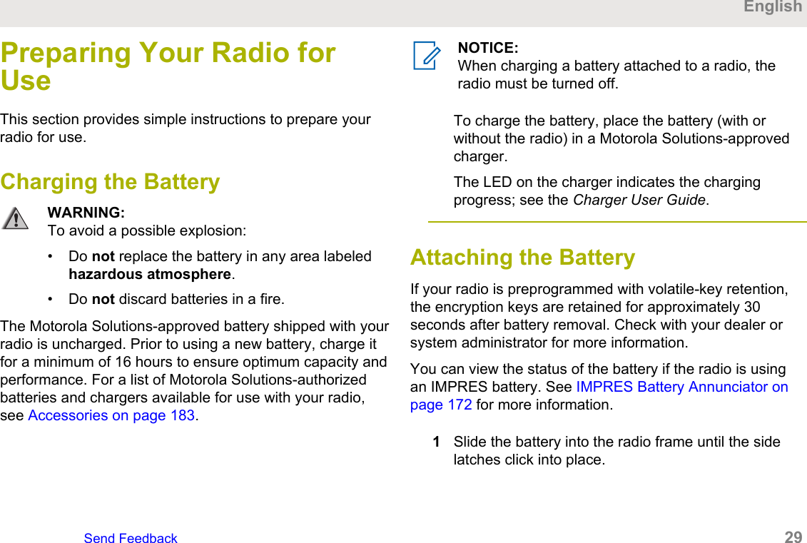
Preparing Your Radio forUseThis section provides simple instructions to prepare yourradio for use.Charging the BatteryWARNING:To avoid a possible explosion:• Do not replace the battery in any area labeledhazardous atmosphere.• Do not discard batteries in a fire.The Motorola Solutions-approved battery shipped with yourradio is uncharged. Prior to using a new battery, charge itfor a minimum of 16 hours to ensure optimum capacity andperformance. For a list of Motorola Solutions-authorizedbatteries and chargers available for use with your radio,see Accessories on page 183.NOTICE:When charging a battery attached to a radio, theradio must be turned off.To charge the battery, place the battery (with orwithout the radio) in a Motorola Solutions-approvedcharger.The LED on the charger indicates the chargingprogress; see the Charger User Guide.Attaching the Battery If your radio is preprogrammed with volatile-key retention,the encryption keys are retained for approximately 30seconds after battery removal. Check with your dealer orsystem administrator for more information.You can view the status of the battery if the radio is usingan IMPRES battery. See IMPRES Battery Annunciator onpage 172 for more information.1Slide the battery into the radio frame until the sidelatches click into place.EnglishSend Feedback   29
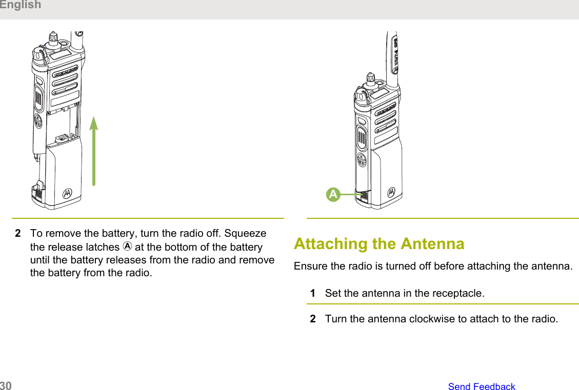
2To remove the battery, turn the radio off. Squeezethe release latches   at the bottom of the batteryuntil the battery releases from the radio and removethe battery from the radio.AAttaching the AntennaEnsure the radio is turned off before attaching the antenna.1Set the antenna in the receptacle.2Turn the antenna clockwise to attach to the radio.English30   Send Feedback
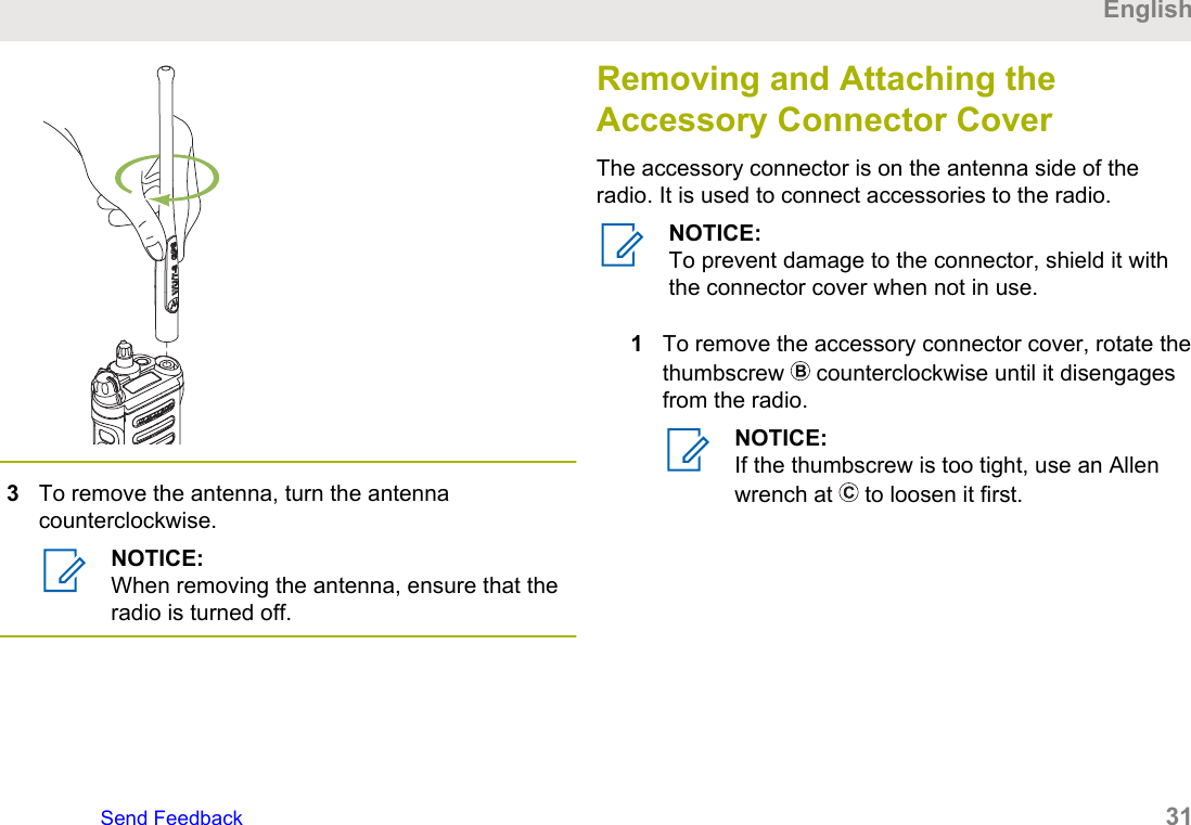
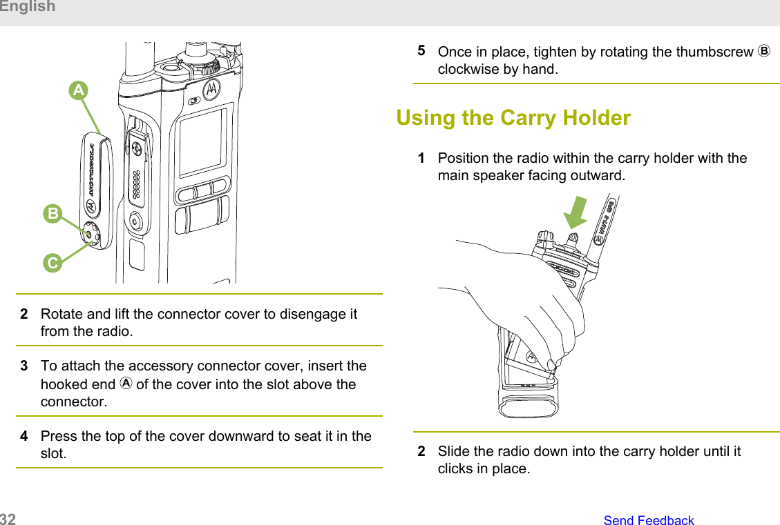
3To remove the antenna, turn the antennacounterclockwise.NOTICE:When removing the antenna, ensure that theradio is turned off.Removing and Attaching theAccessory Connector CoverThe accessory connector is on the antenna side of theradio. It is used to connect accessories to the radio.NOTICE:To prevent damage to the connector, shield it withthe connector cover when not in use.1To remove the accessory connector cover, rotate thethumbscrew   counterclockwise until it disengagesfrom the radio.NOTICE:If the thumbscrew is too tight, use an Allenwrench at   to loosen it first.EnglishSend Feedback   31
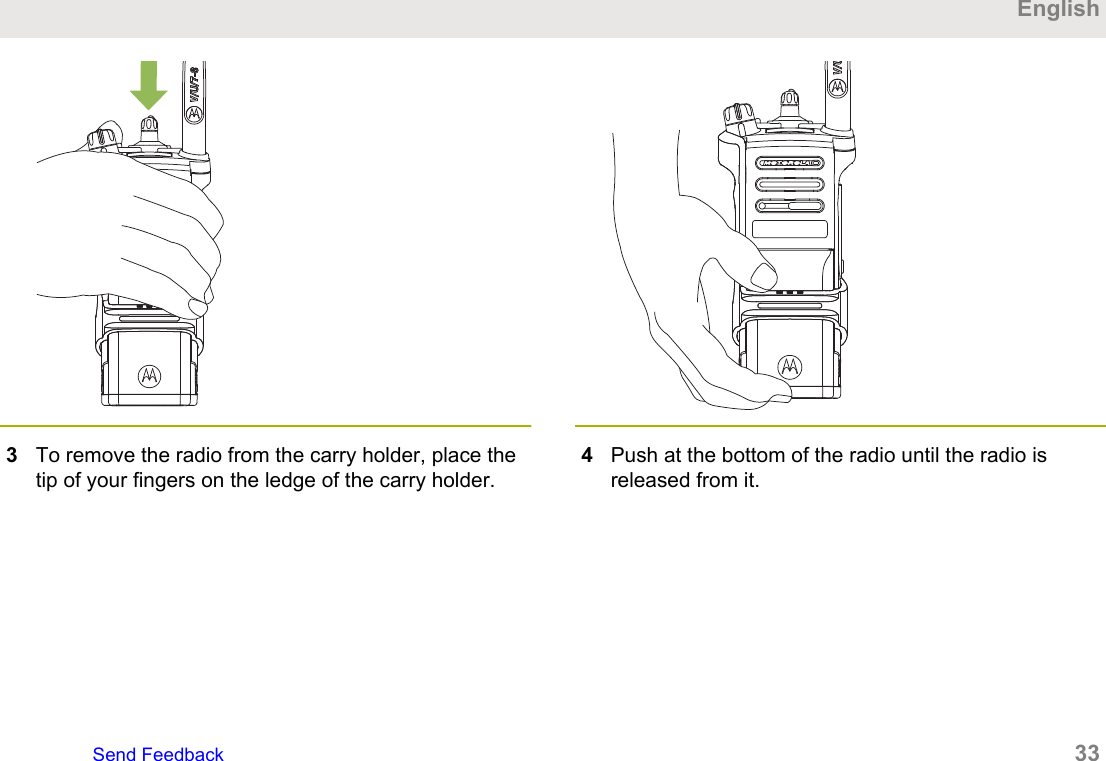
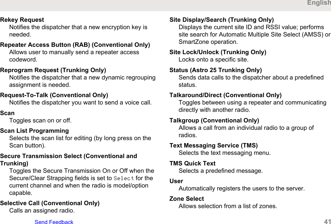
CBA2Rotate and lift the connector cover to disengage itfrom the radio.3To attach the accessory connector cover, insert thehooked end   of the cover into the slot above theconnector.4Press the top of the cover downward to seat it in theslot.5Once in place, tighten by rotating the thumbscrew clockwise by hand.Using the Carry Holder1Position the radio within the carry holder with themain speaker facing outward.2Slide the radio down into the carry holder until itclicks in place.English32   Send Feedback
3To remove the radio from the carry holder, place thetip of your fingers on the ledge of the carry holder.4Push at the bottom of the radio until the radio isreleased from it.EnglishSend Feedback   33
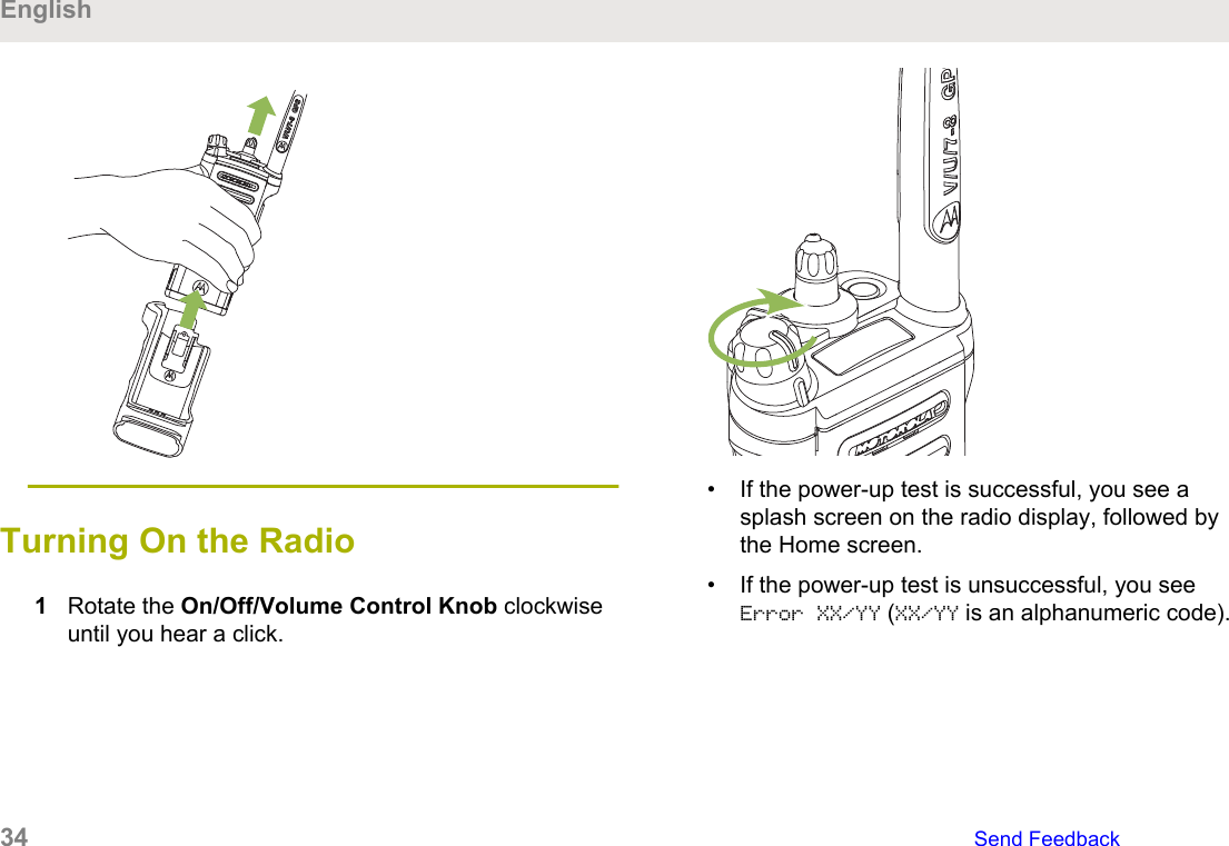
Turning On the Radio 1Rotate the On/Off/Volume Control Knob clockwiseuntil you hear a click.• If the power-up test is successful, you see asplash screen on the radio display, followed bythe Home screen.• If the power-up test is unsuccessful, you seeError XX/YY (XX/YY is an alphanumeric code).English34   Send Feedback
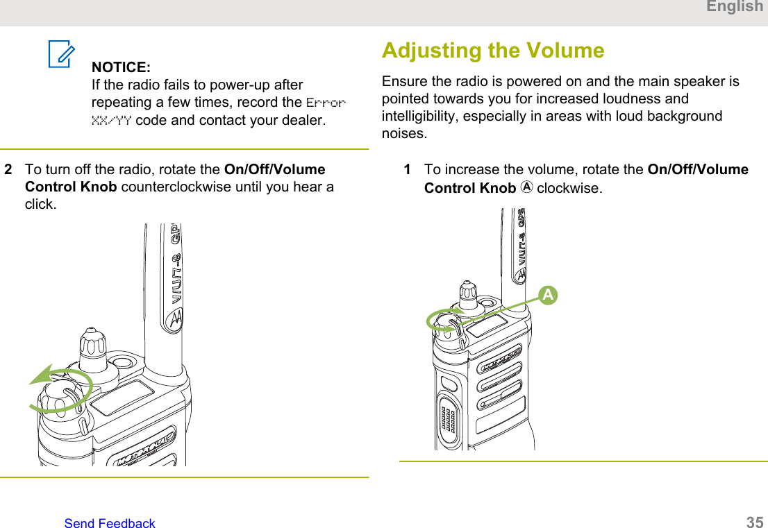
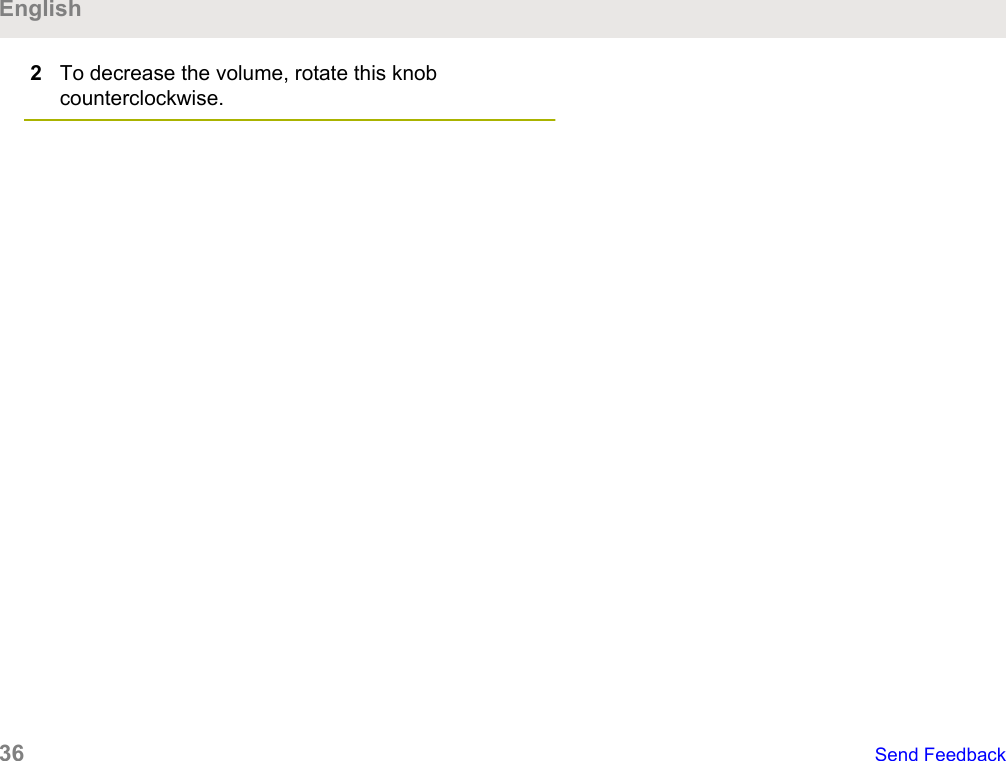
NOTICE:If the radio fails to power-up afterrepeating a few times, record the ErrorXX/YY code and contact your dealer.2To turn off the radio, rotate the On/Off/VolumeControl Knob counterclockwise until you hear aclick.Adjusting the VolumeEnsure the radio is powered on and the main speaker ispointed towards you for increased loudness andintelligibility, especially in areas with loud backgroundnoises.1To increase the volume, rotate the On/Off/VolumeControl Knob   clockwise.AEnglishSend Feedback   35
2To decrease the volume, rotate this knobcounterclockwise.English36   Send Feedback
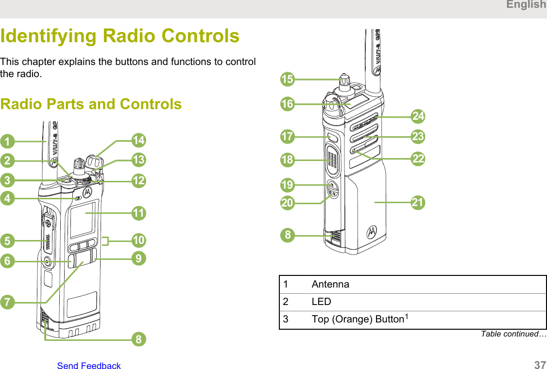
Identifying Radio ControlsThis chapter explains the buttons and functions to controlthe radio.Radio Parts and Controls9101112131481234567151617181920 2122232481 Antenna2 LED3 Top (Orange) Button1Table continued…EnglishSend Feedback   37
4 Microphone5 Accessory Connector6 Home Button7 4–Way Navigation Button8 Battery Latch9 Data Feature Button10 Menu Select Button11 Main Display12 2–Position Concentric Switch113 3–Position A/B/C Switch114 On/Off/Volume Control Knob15 16–Position Select Knob116 Top Display17 Top Side (Select) Button118 Push-to-Talk (PTT) Button19 Side Button 11Table continued…20 Side Button 2121 Battery22 Bluetooth Pairing Location Indicator23 Main Speaker24 MicrophoneProgrammable FeaturesAny reference in this manual to controls that arepreprogrammed means that a qualified radio technicianmust use the radio programming software to assign afeature to a control.Your dealer can program the programmable buttons asshortcuts to radio functions or preset channels/groupsdepending on the duration of a button press:PressPressing and releasing rapidly.Long pressPressing and holding for the preprogrammed duration(between 0.25 and 3.75 seconds).1These radio controls/buttons are programmable.English38   Send Feedback
Hold downKeeping the button pressed.Assignable Radio FunctionsBluetooth On/OffAllows you to turn on/off the Bluetooth.Bluetooth ConfigurationAllows you to access to the Bluetooth menu.Bluetooth Audio RerouteAllows you to toggle the audio route between radiospeaker or Remote Speaker Microphone and Bluetoothheadset.Bluetooth Headset PTTKeys up the Bluetooth Headset microphone.Bluetooth Data DevicesPairs with the data devices for data transfer.Bluetooth Clear All PairingAllows you to clear all pairing information for Bluetooth.This is accessed by a long press of the BluetoothOn/Off Button.Bluetooth Inquiry On/OffEnables Bluetooth Search feature.Bluetooth Discoverable On/OffEnables Bluetooth visibility. This is accessed by a longpress of the Bluetooth Inquiry On/Off Button.Call AlertAllows the radio to function like a pager, or to verify if aradio is active on the system.Call ResponseAllows you to answer a private call.ChannelSelects a channel.ContactsSelects the Contacts menu.Dynamic Priority (Conventional Only)Allows any channel in a Scan List (except for thePriority-One channel) to temporarily replace the Priority-Two channel.EmergencyDepending on the programming, initiates or cancels anemergency alarm or call.Internet Protocol AddressDisplay the Internet Protocol (IP) address, device name,and status of the radio.EnglishSend Feedback   39
LocationDetermines the current location (latitude, longitude, timeand date), and also the distance and bearing to anotherlocation or turns the GPS functionality on or off for alllocations.Man Down ClearClears the Man Down mode alarm that is triggeredwhen your radio achieves or passes a tilt anglethreshold or a combination of the angle threshold and amotion sensitivity level.MessageEnters the current message list.Mode SelectLong-press programs a button with the current zoneand channel of the radio; once programmed, the short-press of that button changes the radio zone channel tothe programmed zone and channel.Monitor (Conventional Only)Monitors a selected channel for all radio traffic untilfunction is disabled.Multiple Private Line (Conventional Only)Selects the Multiple Private Line lists.Nuisance DeleteTemporarily removes an unwanted channel, except forpriority channels or the designated transmit channelfrom the scan list.One Touch 1–4Launches a specific feature with one single button-press. You can setup as many as four separatelyprogrammed buttons for four different features.PhoneAllows you to make and receive calls similar to standardphone calls.Private Call (Trunking Only)Allows a call from one individual radio to another.Private Line Defeat (Conventional Only)Overrides any coded squelch (DPL or PL) that ispreprogrammed to a channel.Radio ProfilesAllows easy access to a set of preprogrammed visualand audio settings of the radio.Recent CallsAllows easy access to the list of calls recently receivedor made.English40   Send Feedback
Rekey RequestNotifies the dispatcher that a new encryption key isneeded.Repeater Access Button (RAB) (Conventional Only)Allows user to manually send a repeater accesscodeword.Reprogram Request (Trunking Only)Notifies the dispatcher that a new dynamic regroupingassignment is needed.Request-To-Talk (Conventional Only)Notifies the dispatcher you want to send a voice call.ScanToggles scan on or off.Scan List ProgrammingSelects the scan list for editing (by long press on theScan button).Secure Transmission Select (Conventional andTrunking)Toggles the Secure Transmission On or Off when theSecure/Clear Strapping fields is set to Select for thecurrent channel and when the radio is model/optioncapable.Selective Call (Conventional Only)Calls an assigned radio.Site Display/Search (Trunking Only)Displays the current site ID and RSSI value; performssite search for Automatic Multiple Site Select (AMSS) orSmartZone operation.Site Lock/Unlock (Trunking Only)Locks onto a specific site.Status (Astro 25 Trunking Only)Sends data calls to the dispatcher about a predefinedstatus.Talkaround/Direct (Conventional Only)Toggles between using a repeater and communicatingdirectly with another radio.Talkgroup (Conventional Only)Allows a call from an individual radio to a group ofradios.Text Messaging Service (TMS)Selects the text messaging menu.TMS Quick TextSelects a predefined message.UserAutomatically registers the users to the server.Zone SelectAllows selection from a list of zones.EnglishSend Feedback   41
Basic Zone BankProvides access from up to six zones by togglingbetween two banks of three zones, one group of three(A, B, and C) to a second group of three zones (D, E,and F).Enhanced Zone BankProvides access from up to 75 zones by togglingbetween 25 banks (A, B, ... X or Y) of three zones.Wi-Fi®Toggles Wi-Fi on or off.Assignable Settings or UtilityFunctionsKeypad/Controls LockLocks or unlocks the keypad, programmable buttons,switches or rotary knobs.Light/FlipPress the button to toggle the display backlight on oroff; press and hold the button to reverse the content ofthe top display.TX Power LevelToggles transmit power level between high and low.Voice AnnouncementAudibly indicates the current feature mode, Zone orChannel the user has just assigned.Voice MuteToggles voice mute on or off.Volume Set ToneSets the volume set tone.Accessing the PreprogrammedFunctionsYou can access various radio functions through one of thefollowing methods.• A short or long press of the relevant programmablebuttons.• Use the Menu Select Button.• Use the Menu Select and Navigation buttons.English42   Send Feedback
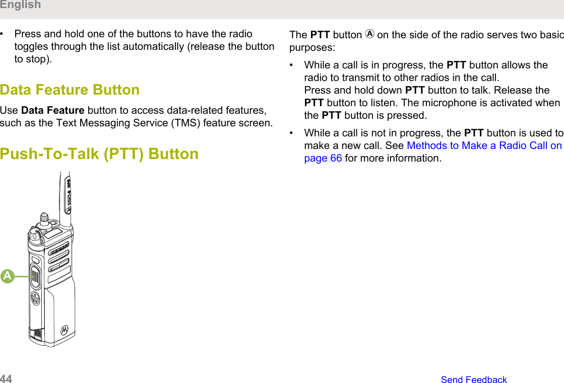
BCDEAA SoftkeysB Menu Select ButtonsC Data Feature ButtonD 4–Way Navigation ButtonE Home ButtonMenu Select ButtonsNOTICE:Check with your dealer or system administrator forthe list of features activated in your radio.Use the Menu Select button to access the menu entry ofyour radio feature. Your radio may be preprogrammeddifferently from the following example, but the steps forselecting a channel may appear as shown below:Press the Menu Select button directly below Chan .Home ButtonPressing the   button returns you to the Home (default)screen. In most cases, this is the current mode. Forselected radio features, the   button is also used to saveuser-edited radio settings or information before returningyou to the Home screen.NOTICE:Some features do not require you to press   to goto the Home screen. Refer to the individual featuresections in this manual for further details on savinguser-edited radio settings or information.4-Way Navigation ButtonUse the 4-Way Navigation Button to scroll up, down, left,or right with one of the following methods.• Press and release one of the buttons to scroll from oneentry to the next one.EnglishSend Feedback   43
• Press and hold one of the buttons to have the radiotoggles through the list automatically (release the buttonto stop).Data Feature ButtonUse Data Feature button to access data-related features,such as the Text Messaging Service (TMS) feature screen.Push-To-Talk (PTT) ButtonAThe PTT button   on the side of the radio serves two basicpurposes:• While a call is in progress, the PTT button allows theradio to transmit to other radios in the call.Press and hold down PTT button to talk. Release thePTT button to listen. The microphone is activated whenthe PTT button is pressed.• While a call is not in progress, the PTT button is used tomake a new call. See Methods to Make a Radio Call onpage 66 for more information.English44   Send Feedback
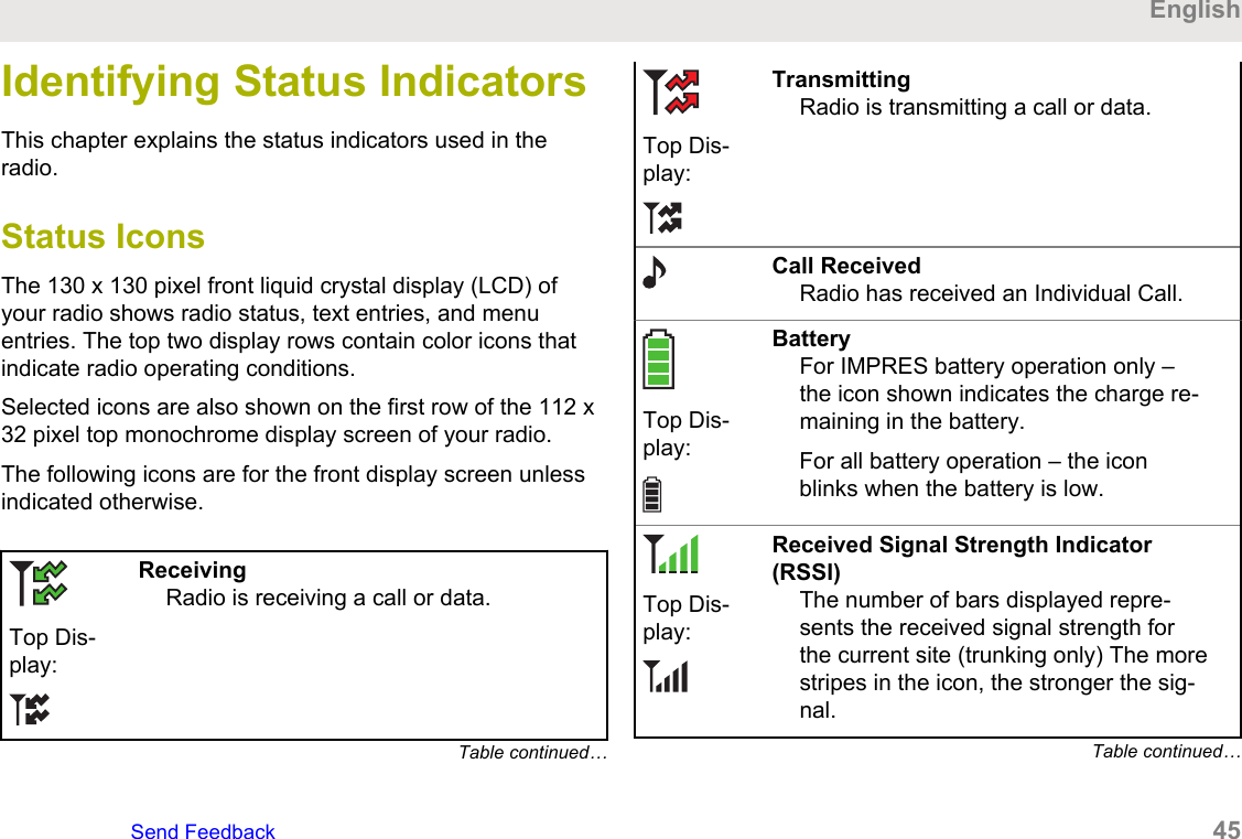
Identifying Status IndicatorsThis chapter explains the status indicators used in theradio.Status IconsThe 130 x 130 pixel front liquid crystal display (LCD) ofyour radio shows radio status, text entries, and menuentries. The top two display rows contain color icons thatindicate radio operating conditions.Selected icons are also shown on the first row of the 112 x32 pixel top monochrome display screen of your radio.The following icons are for the front display screen unlessindicated otherwise.Top Dis-play:ReceivingRadio is receiving a call or data.Table continued…Top Dis-play:TransmittingRadio is transmitting a call or data.Call ReceivedRadio has received an Individual Call.Top Dis-play:BatteryFor IMPRES battery operation only –the icon shown indicates the charge re-maining in the battery.For all battery operation – the iconblinks when the battery is low.Top Dis-play:Received Signal Strength Indicator(RSSI)The number of bars displayed repre-sents the received signal strength forthe current site (trunking only) The morestripes in the icon, the stronger the sig-nal.Table continued…EnglishSend Feedback   45
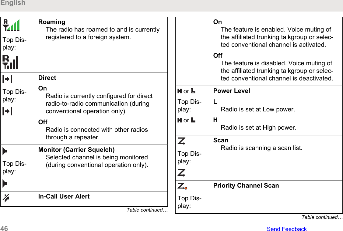
Top Dis-play:RoamingThe radio has roamed to and is currentlyregistered to a foreign system.Top Dis-play:DirectOnRadio is currently configured for directradio-to-radio communication (duringconventional operation only).OffRadio is connected with other radiosthrough a repeater.Top Dis-play:Monitor (Carrier Squelch)Selected channel is being monitored(during conventional operation only).In-Call User AlertTable continued…OnThe feature is enabled. Voice muting ofthe affiliated trunking talkgroup or selec-ted conventional channel is activated.OffThe feature is disabled. Voice muting ofthe affiliated trunking talkgroup or selec-ted conventional channel is deactivated. or Top Dis-play: or Power LevelLRadio is set at Low power.HRadio is set at High power.Top Dis-play:ScanRadio is scanning a scan list.Top Dis-play:Priority Channel ScanTable continued…English46   Send Feedback
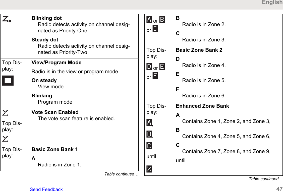
Blinking dotRadio detects activity on channel desig-nated as Priority-One.Steady dotRadio detects activity on channel desig-nated as Priority-Two.Top Dis-play:View/Program ModeRadio is in the view or program mode.On steadyView modeBlinkingProgram modeTop Dis-play:Vote Scan EnabledThe vote scan feature is enabled.Top Dis-play:Basic Zone Bank 1ARadio is in Zone 1.Table continued… or or BRadio is in Zone 2.CRadio is in Zone 3.Top Dis-play: or or Basic Zone Bank 2DRadio is in Zone 4.ERadio is in Zone 5.FRadio is in Zone 6.Top Dis-play:,,untilEnhanced Zone BankAContains Zone 1, Zone 2, and Zone 3,BContains Zone 4, Zone 5, and Zone 6,CContains Zone 7, Zone 8, and Zone 9,untilTable continued…EnglishSend Feedback   47
or XContains Zone 70, Zone 71, and Zone72,YContains Zone 73, Zone 74, and Zone75.Top Dis-play:Secure OperationOnSecure operation.OffClear operation.BlinkingReceiving an encrypted voice call.AES Secure OperationOnAES secure operation.OffClear operation.BlinkingReceiving an encrypted voice call.Table continued…GPS SignalOnFeature is enabled and signal is availa-ble.OffFeature is disabled.BlinkingFeature is enabled, but no signal isavailable.User Login Indicator (IP Packet Data)OnUser is currently associated with the ra-dio.OffUser is currently not associated with theradio.BlinkingDevice registration or user registrationwith the server failed due to an invalidusername or pin.Table continued…English48   Send Feedback
InvertedUser successfully login to the securedIP Packet Data.Data ActivityData activity is present.Top Dis-play:Bluetooth OnBluetooth is on and ready for Bluetoothconnection.Top Dis-play:Bluetooth ConnectedBluetooth is currently connected to theexternal Bluetooth device.The radio Wi-Fi® network is connected.The number of bars displayed representsthe signal strength of the Wi-Fi signal.Text Messaging Service (TMS)IndicatorsStatus icons and menu options shown here help you towork more efficiently with TMS feature. See TextMessaging Service (TMS) on page 107 for moreinformation.TMS Status IconsThe following icons appear on the radio display when yousend and receive text messages.Inbox FullThe Inbox is full.Message SentThe text message is sent successfully.Message UnsentThe text message cannot be sent.Unread MessageTable continued…EnglishSend Feedback   49
• User receives a new message.• The selected text message in the Inboxhas not been read.Read MessageThe selected text message in the Inbox hasbeen read.Normal MessageUser is composing a message with normalpriority and without a request for a reply.Message IndexIndicates the index of the current messagethe user is viewing.Example: If the user is looking at the thirdmessage out of a total of six messages in theInbox folder, the icon is displayed as the iconon the left column.Priority Status• The “Priority” feature is toggled on beforethe message is sent.Table continued…• Messages in the Inbox folder are flaggedwith “Priority”.Request Reply• The “Request Reply” feature is toggled onbefore the message is sent.• Messages in the Inbox folder are flaggedwith “Request Reply”.Priority Status and Request Reply• User is composing a message with a pri-ority status and a request for a reply.• Messages in the Inbox folder are flaggedwith “Priority” and “Request Reply”.English50   Send Feedback
TMS Menu OptionsThe following menu options appear on the radio displaywhen you send and receive text messages.MenuOptionDescription/FunctionBack Brings you back to the previous screen.Clr Deletes all messages.Del Deletes a message or text.Exit Exits to the Home screen.No Returns to the previous screen.Optn Brings you to the Options main screen.Rply Replies to a message.Sel Selects the highlighted command.Send Sends the message.Yes Updates or saves a command.Call Type IconsThe following icons appear on the radio main display, whenyou make or receive a call, or view selected call lists, toindicate the different call types associated with an alias orID.Radio number.Radio number added to a Call List.Mobile number.Mobile number added to a Call List.Landline phone number.Landline phone number added to a CallList.Table continued…EnglishSend Feedback   51
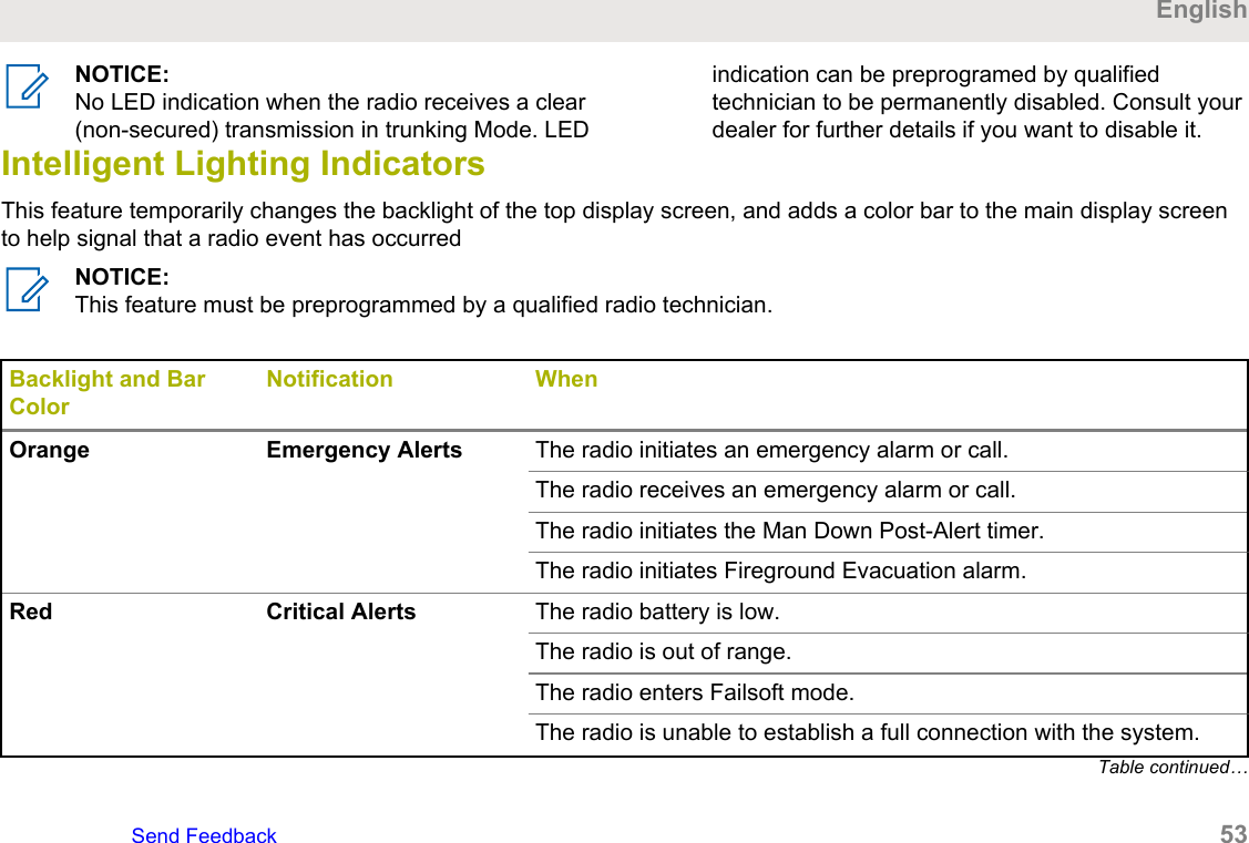
Incoming call or data.Outgoing call or data.Incoming emergency call.LED IndicatorThe LED indicator   shows the operational status of yourradio.ASolid redRadio is transmitting.Blinking redRadio is transmitting at low battery condition.Double blinking redRadio is in Emergency Mode.Rapidly blinking redRadio has failed the self test upon powering up orencountered a fatal error.Solid yellow (Conventional Only)Channel is busy.Blinking yellowRadio is receiving a secured transmission.Solid greenRadio is powering up, or is on a non-priority channelwhile in the Scan List Programming mode.Blinking greenRadio is receiving an individual or telephone call, or ison a Priority-Two channel while in the Scan ListProgramming mode.Rapidly blinking greenRadio is on a Priority-One channel while in the ScanList Programming mode.English52   Send Feedback
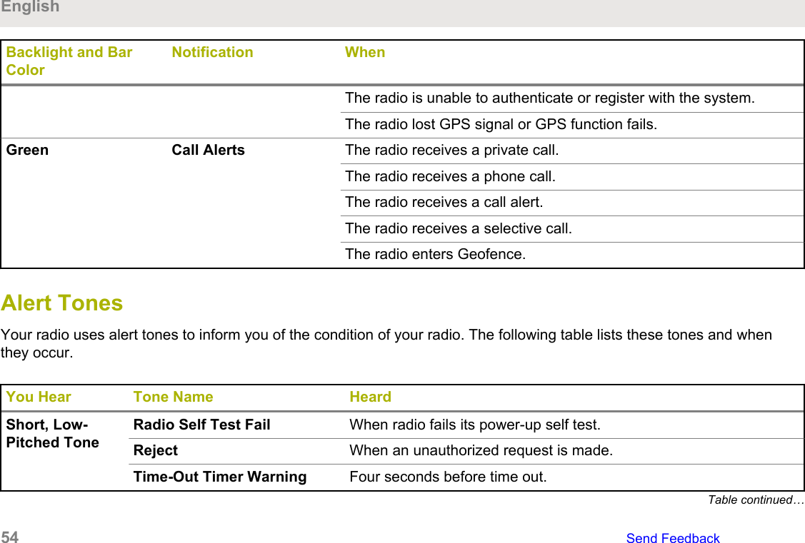
NOTICE:No LED indication when the radio receives a clear(non-secured) transmission in trunking Mode. LEDindication can be preprogramed by qualifiedtechnician to be permanently disabled. Consult yourdealer for further details if you want to disable it.Intelligent Lighting IndicatorsThis feature temporarily changes the backlight of the top display screen, and adds a color bar to the main display screento help signal that a radio event has occurredNOTICE:This feature must be preprogrammed by a qualified radio technician.Backlight and BarColorNotification WhenOrange Emergency Alerts The radio initiates an emergency alarm or call.The radio receives an emergency alarm or call.The radio initiates the Man Down Post-Alert timer.The radio initiates Fireground Evacuation alarm.Red Critical Alerts The radio battery is low.The radio is out of range.The radio enters Failsoft mode.The radio is unable to establish a full connection with the system.Table continued…EnglishSend Feedback   53
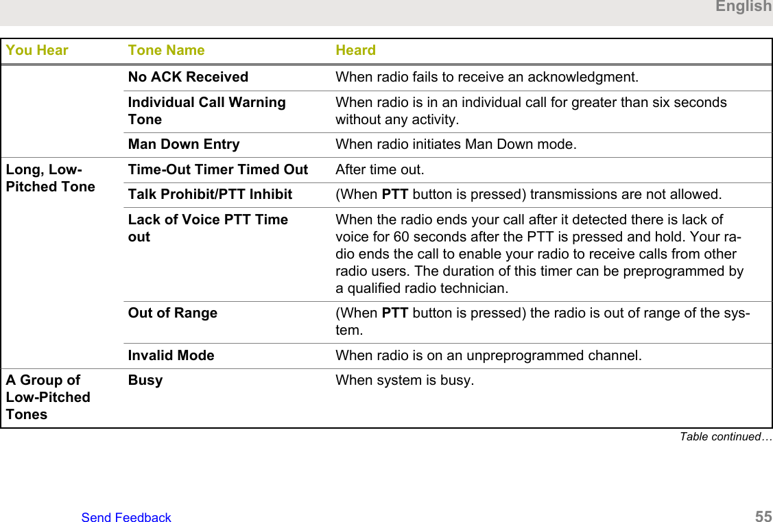
Backlight and BarColorNotification WhenThe radio is unable to authenticate or register with the system.The radio lost GPS signal or GPS function fails.Green Call Alerts The radio receives a private call.The radio receives a phone call.The radio receives a call alert.The radio receives a selective call.The radio enters Geofence.Alert Tones Your radio uses alert tones to inform you of the condition of your radio. The following table lists these tones and whenthey occur.You Hear Tone Name HeardShort, Low-Pitched ToneRadio Self Test Fail When radio fails its power-up self test.Reject When an unauthorized request is made.Time-Out Timer Warning Four seconds before time out.Table continued…English54   Send Feedback
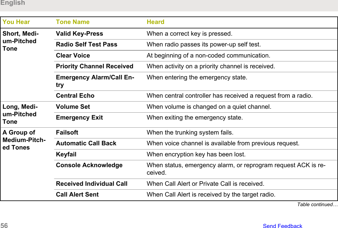
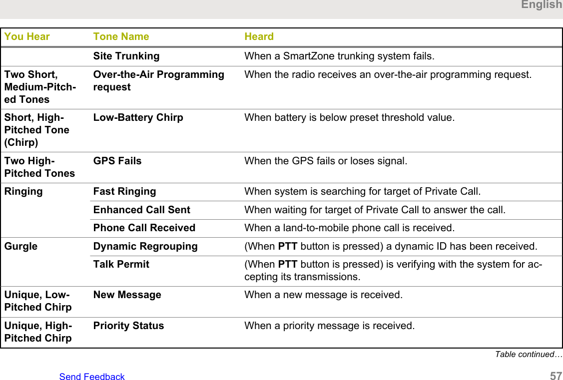
You Hear Tone Name HeardNo ACK Received When radio fails to receive an acknowledgment.Individual Call WarningToneWhen radio is in an individual call for greater than six secondswithout any activity.Man Down Entry When radio initiates Man Down mode.Long, Low-Pitched ToneTime-Out Timer Timed Out After time out.Talk Prohibit/PTT Inhibit (When PTT button is pressed) transmissions are not allowed.Lack of Voice PTT TimeoutWhen the radio ends your call after it detected there is lack ofvoice for 60 seconds after the PTT is pressed and hold. Your ra-dio ends the call to enable your radio to receive calls from otherradio users. The duration of this timer can be preprogrammed bya qualified radio technician.Out of Range (When PTT button is pressed) the radio is out of range of the sys-tem.Invalid Mode When radio is on an unpreprogrammed channel.A Group ofLow-PitchedTonesBusy When system is busy.Table continued…EnglishSend Feedback   55
You Hear Tone Name HeardShort, Medi-um-PitchedToneValid Key-Press When a correct key is pressed.Radio Self Test Pass When radio passes its power-up self test.Clear Voice At beginning of a non-coded communication.Priority Channel Received When activity on a priority channel is received.Emergency Alarm/Call En-tryWhen entering the emergency state.Central Echo When central controller has received a request from a radio.Long, Medi-um-PitchedToneVolume Set When volume is changed on a quiet channel.Emergency Exit When exiting the emergency state.A Group ofMedium-Pitch-ed TonesFailsoft When the trunking system fails.Automatic Call Back When voice channel is available from previous request.Keyfail When encryption key has been lost.Console Acknowledge When status, emergency alarm, or reprogram request ACK is re-ceived.Received Individual Call When Call Alert or Private Call is received.Call Alert Sent When Call Alert is received by the target radio.Table continued…English56   Send Feedback
You Hear Tone Name HeardSite Trunking When a SmartZone trunking system fails.Two Short,Medium-Pitch-ed TonesOver-the-Air ProgrammingrequestWhen the radio receives an over-the-air programming request.Short, High-Pitched Tone(Chirp)Low-Battery Chirp When battery is below preset threshold value.Two High-Pitched TonesGPS Fails When the GPS fails or loses signal.Ringing Fast Ringing When system is searching for target of Private Call.Enhanced Call Sent When waiting for target of Private Call to answer the call.Phone Call Received When a land-to-mobile phone call is received.Gurgle Dynamic Regrouping (When PTT button is pressed) a dynamic ID has been received.Talk Permit (When PTT button is pressed) is verifying with the system for ac-cepting its transmissions.Unique, Low-Pitched ChirpNew Message When a new message is received.Unique, High-Pitched ChirpPriority Status When a priority message is received.Table continued…EnglishSend Feedback   57
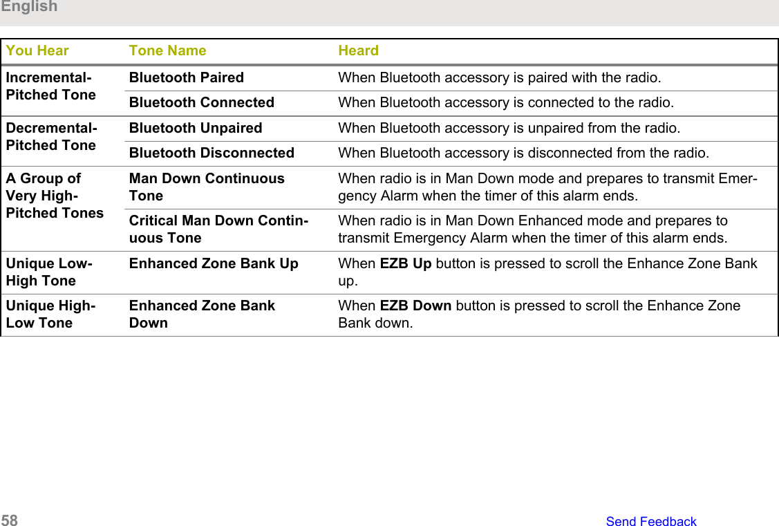
You Hear Tone Name HeardIncremental-Pitched ToneBluetooth Paired When Bluetooth accessory is paired with the radio.Bluetooth Connected When Bluetooth accessory is connected to the radio.Decremental-Pitched ToneBluetooth Unpaired When Bluetooth accessory is unpaired from the radio.Bluetooth Disconnected When Bluetooth accessory is disconnected from the radio.A Group ofVery High-Pitched TonesMan Down ContinuousToneWhen radio is in Man Down mode and prepares to transmit Emer-gency Alarm when the timer of this alarm ends.Critical Man Down Contin-uous ToneWhen radio is in Man Down Enhanced mode and prepares totransmit Emergency Alarm when the timer of this alarm ends.Unique Low-High ToneEnhanced Zone Bank Up When EZB Up button is pressed to scroll the Enhance Zone Bankup.Unique High-Low ToneEnhanced Zone BankDownWhen EZB Down button is pressed to scroll the Enhance ZoneBank down.English58   Send Feedback
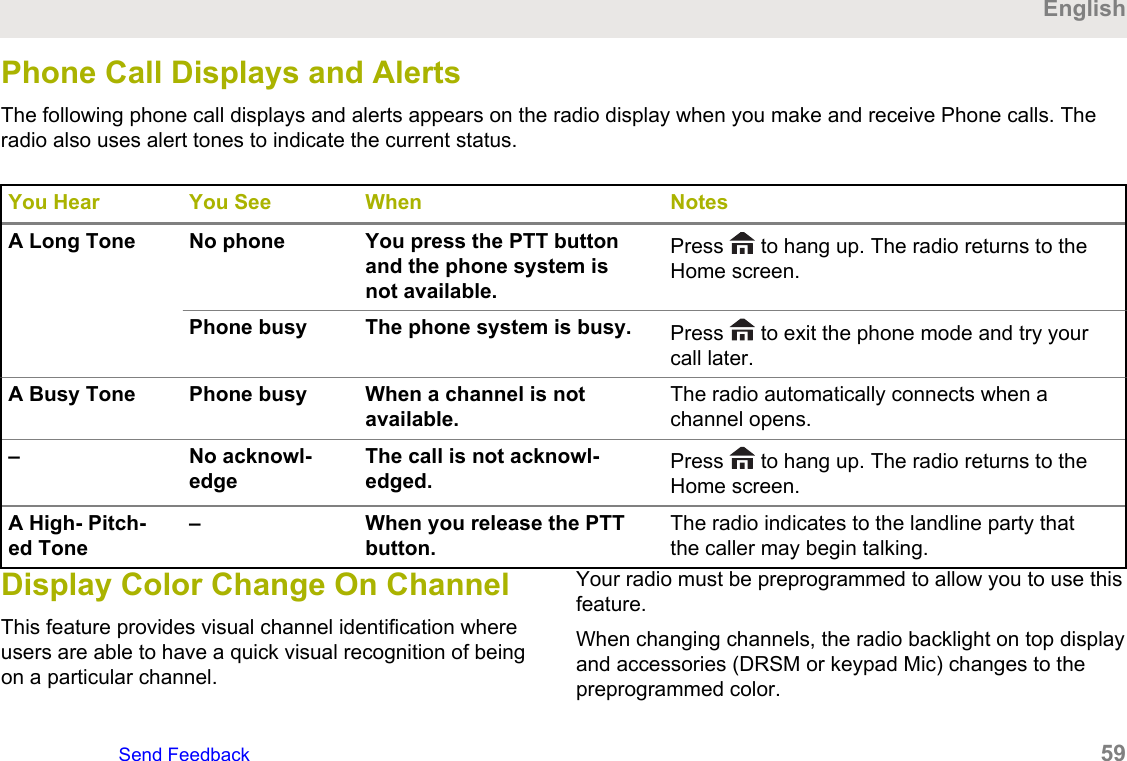
Phone Call Displays and AlertsThe following phone call displays and alerts appears on the radio display when you make and receive Phone calls. Theradio also uses alert tones to indicate the current status.You Hear You See When NotesA Long Tone No phone You press the PTT buttonand the phone system isnot available.Press   to hang up. The radio returns to theHome screen.Phone busy The phone system is busy. Press   to exit the phone mode and try yourcall later.A Busy Tone Phone busy When a channel is notavailable.The radio automatically connects when achannel opens.– No acknowl-edgeThe call is not acknowl-edged. Press   to hang up. The radio returns to theHome screen.A High- Pitch-ed Tone– When you release the PTTbutton.The radio indicates to the landline party thatthe caller may begin talking.Display Color Change On ChannelThis feature provides visual channel identification whereusers are able to have a quick visual recognition of beingon a particular channel.Your radio must be preprogrammed to allow you to use thisfeature.When changing channels, the radio backlight on top displayand accessories (DRSM or keypad Mic) changes to thepreprogrammed color.EnglishSend Feedback   59
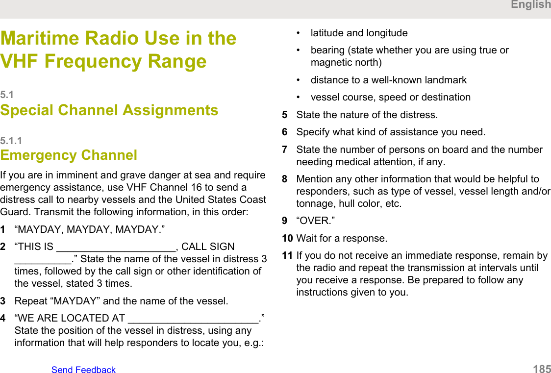
The radio backlight on top display changes to white and ifconnected to accessories, the DRSM backlight changes towhite and the keypad mic backlight changes to green forthe following scenarios:• When changing to or powering up on an invalidchannels such as unprogrammed channels, receiverfrequency error channel and blank channelsFor hard key zeroize, key loading, and scan listprogramming, the backlight follows the home channelbacklight color.HAZLOC Battery Type DetectionThis feature alerts the user when there is a HAZLOCcertification mismatch between the radio and the battery.This feature supports IMPRES batteries only.During power up, if there is a mismatch, the followingscenarios occurs:• The radio repetitively displays Wrong Battery with redintelligent backlight• The Battery icon blinks continuously• A repetitive tone sounds• LED blinks RED continuouslyNOTICE:The radio alerts the user when NNTN8921 andNNTN8930 batteries are attached to theAPX8000, APX8000H, or APX8000XE radios.These batteries are not supported by theAPX8000, APX8000H, or APX8000XE radios.The APX8000 and APX8000H is not HAZLOCcertified and will reset if these batteries are used.Refer to the radio FM or UL Manual for moreinformation.The radio does not display any indication whenthe radio is connected to the charger, when theradio and battery match, or when the radiocertification type is configured as "None" inCustomer Programming Software (CPS).This feature is enabled through CPS configuration. Checkwith your dealer or system administrator for moreinformation.English60   Send Feedback
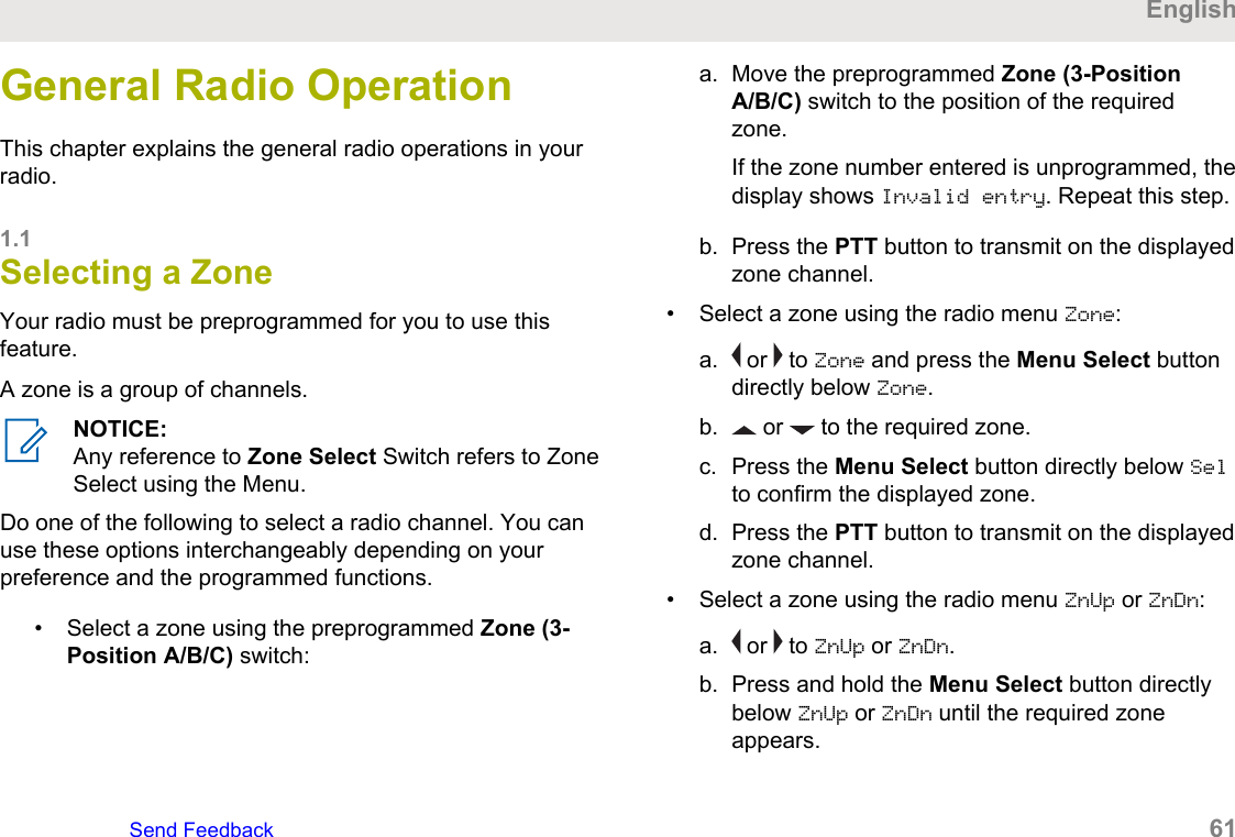
General Radio OperationThis chapter explains the general radio operations in yourradio.1.1Selecting a ZoneYour radio must be preprogrammed for you to use thisfeature.A zone is a group of channels.NOTICE:Any reference to Zone Select Switch refers to ZoneSelect using the Menu.Do one of the following to select a radio channel. You canuse these options interchangeably depending on yourpreference and the programmed functions.• Select a zone using the preprogrammed Zone (3-Position A/B/C) switch:a. Move the preprogrammed Zone (3-PositionA/B/C) switch to the position of the requiredzone.If the zone number entered is unprogrammed, thedisplay shows Invalid entry. Repeat this step.b. Press the PTT button to transmit on the displayedzone channel.• Select a zone using the radio menu Zone:a.  or   to Zone and press the Menu Select buttondirectly below Zone.b.  or   to the required zone.c. Press the Menu Select button directly below Selto confirm the displayed zone.d. Press the PTT button to transmit on the displayedzone channel.• Select a zone using the radio menu ZnUp or ZnDn:a.  or   to ZnUp or ZnDn.b. Press and hold the Menu Select button directlybelow ZnUp or ZnDn until the required zoneappears.EnglishSend Feedback   61
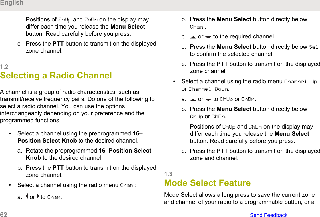
Positions of ZnUp and ZnDn on the display maydiffer each time you release the Menu Selectbutton. Read carefully before you press.c. Press the PTT button to transmit on the displayedzone channel.1.2Selecting a Radio ChannelA channel is a group of radio characteristics, such astransmit/receive frequency pairs. Do one of the following toselect a radio channel. You can use the optionsinterchangeably depending on your preference and theprogrammed functions.• Select a channel using the preprogrammed 16–Position Select Knob to the desired channel.a. Rotate the preprogrammed 16–Position SelectKnob to the desired channel.b. Press the PTT button to transmit on the displayedzone channel.• Select a channel using the radio menu Chan :a.  or   to Chan.b. Press the Menu Select button directly belowChan .c.  or   to the required channel.d. Press the Menu Select button directly below Selto confirm the selected channel.e. Press the PTT button to transmit on the displayedzone channel.• Select a channel using the radio menu Channel Upor Channel Down:a.  or   to ChUp or ChDn.b. Press the Menu Select button directly belowChUp or ChDn.Positions of ChUp and ChDn on the display maydiffer each time you release the Menu Selectbutton. Read carefully before you press.c. Press the PTT button to transmit on the displayedzone and channel.1.3Mode Select FeatureMode Select allows a long press to save the current zoneand channel of your radio to a programmable button, or aEnglish62   Send Feedback
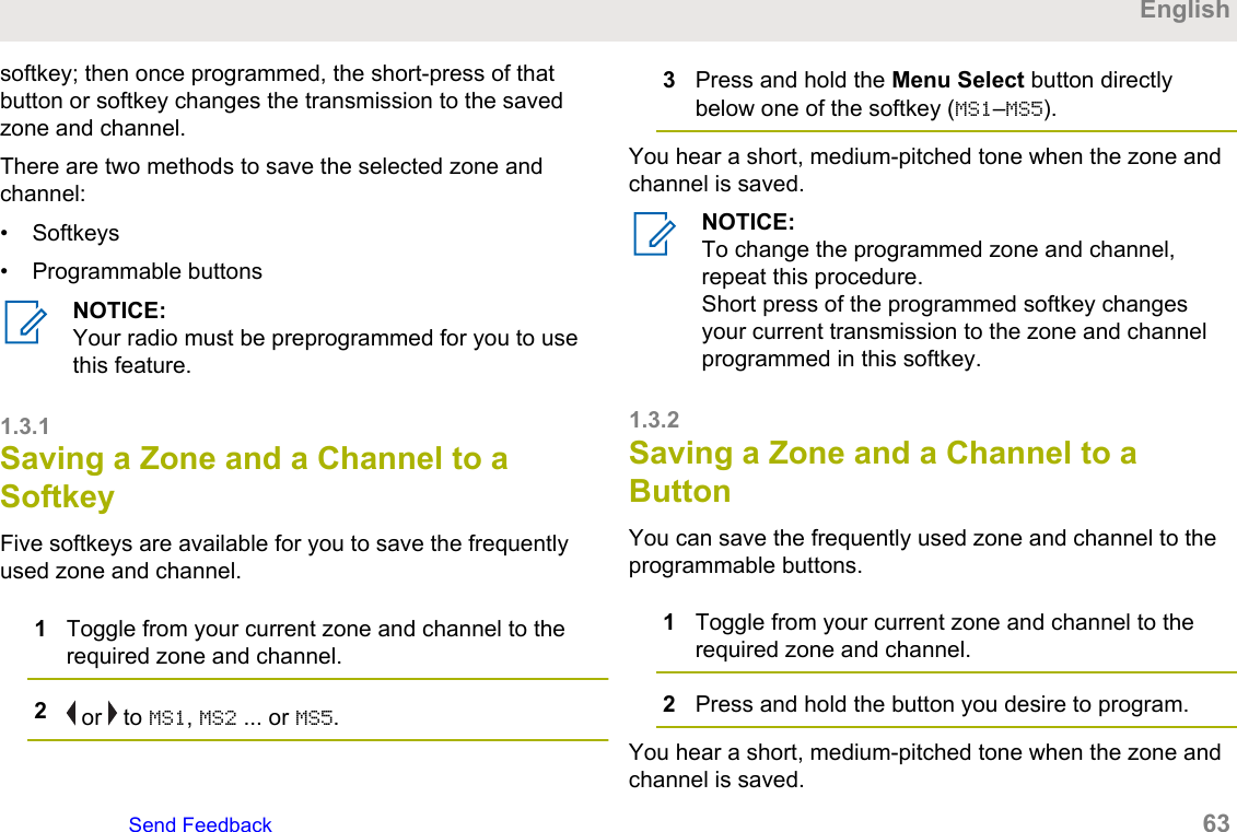
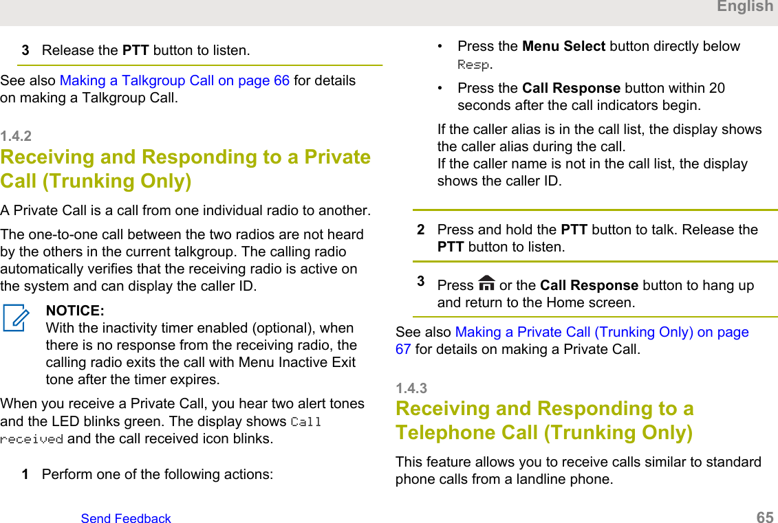
softkey; then once programmed, the short-press of thatbutton or softkey changes the transmission to the savedzone and channel.There are two methods to save the selected zone andchannel:• Softkeys• Programmable buttonsNOTICE:Your radio must be preprogrammed for you to usethis feature.1.3.1Saving a Zone and a Channel to aSoftkeyFive softkeys are available for you to save the frequentlyused zone and channel.1Toggle from your current zone and channel to therequired zone and channel.2 or   to MS1, MS2 ... or MS5.3Press and hold the Menu Select button directlybelow one of the softkey (MS1–MS5).You hear a short, medium-pitched tone when the zone andchannel is saved.NOTICE:To change the programmed zone and channel,repeat this procedure.Short press of the programmed softkey changesyour current transmission to the zone and channelprogrammed in this softkey.1.3.2Saving a Zone and a Channel to aButtonYou can save the frequently used zone and channel to theprogrammable buttons.1Toggle from your current zone and channel to therequired zone and channel.2Press and hold the button you desire to program.You hear a short, medium-pitched tone when the zone andchannel is saved.EnglishSend Feedback   63
NOTICE:Repeat this procedure to change the zone andchannel of the programmed button.Short press of the programmed button changes yourcurrent transmission to the zone and channelprogrammed in this button.1.4Receiving and Responding to aRadio CallOnce you have selected the required channel and/or zone,you can proceed to receive and respond to calls.The radio shows different indicators based on the systemthe radio is configured.• The LED lights up solid red while the radio istransmitting.• In conventional mode, the LED lights up solid yellowwhen the radio is receiving a transmission.• In trunking mode, there is no LED indication when theradio receives a transmission.• If the radio is receiving a secure transmission, the LEDblinks yellow.1.4.1Receiving and Responding to aTalkgroup CallTo receive a call from a group of users, your radio must beconfigured as part of that talkgroup.When you receive a talkgroup call (while on the Homescreen) the radio displays the following depending on thesystem your radio is configured to:• For ASTRO Conventional system, the LED lights upsolid yellow. The display shows the talkgroup alias orID, and the caller alias or ID.• For Trunking system, the display shows the caller aliasor ID.1Hold the radio vertically 1 to 2 inches (2.5 to 5.0 cm)from your mouth.2Press the PTT button to respond to the call.The LED lights up solid red.English64   Send Feedback
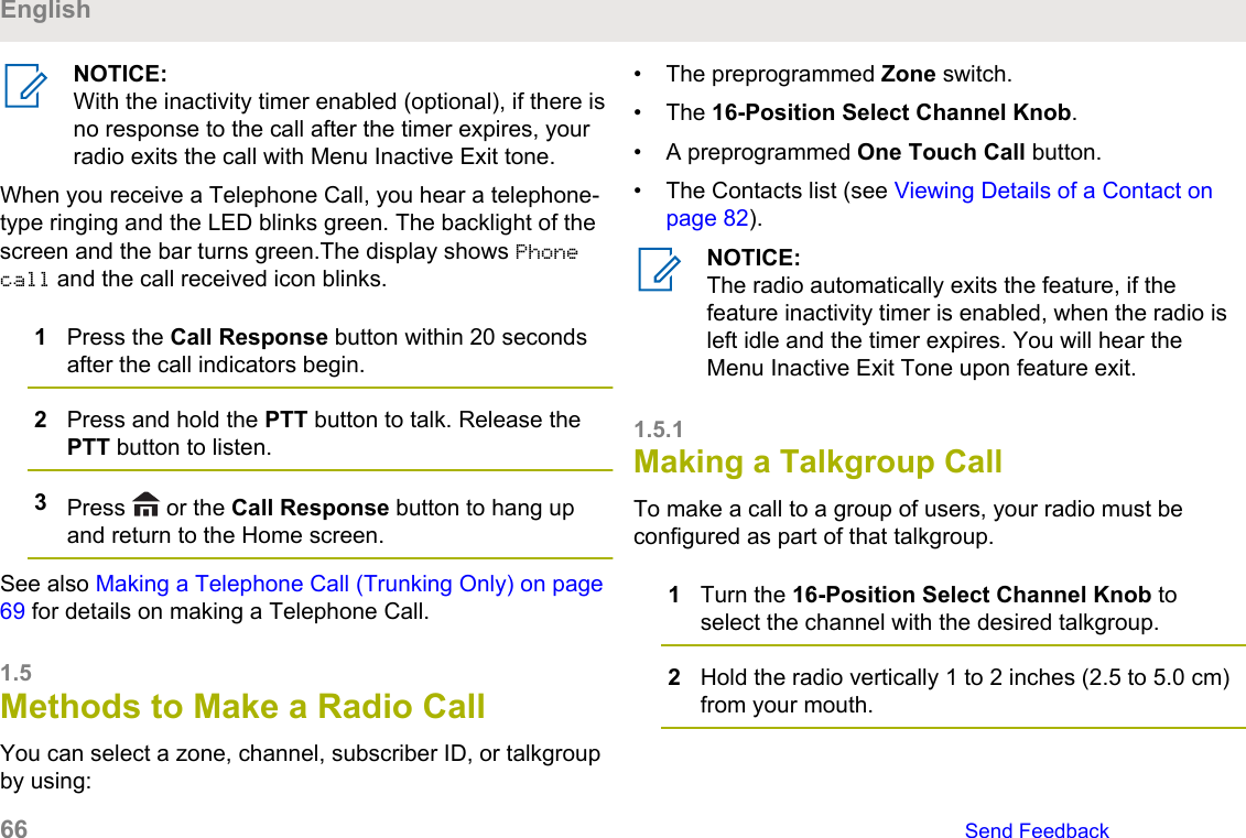
3Release the PTT button to listen.See also Making a Talkgroup Call on page 66 for detailson making a Talkgroup Call.1.4.2Receiving and Responding to a PrivateCall (Trunking Only)A Private Call is a call from one individual radio to another.The one-to-one call between the two radios are not heardby the others in the current talkgroup. The calling radioautomatically verifies that the receiving radio is active onthe system and can display the caller ID.NOTICE:With the inactivity timer enabled (optional), whenthere is no response from the receiving radio, thecalling radio exits the call with Menu Inactive Exittone after the timer expires.When you receive a Private Call, you hear two alert tonesand the LED blinks green. The display shows Callreceived and the call received icon blinks.1Perform one of the following actions:• Press the Menu Select button directly belowResp.• Press the Call Response button within 20seconds after the call indicators begin.If the caller alias is in the call list, the display showsthe caller alias during the call.If the caller name is not in the call list, the displayshows the caller ID.2Press and hold the PTT button to talk. Release thePTT button to listen.3Press   or the Call Response button to hang upand return to the Home screen.See also Making a Private Call (Trunking Only) on page67 for details on making a Private Call.1.4.3Receiving and Responding to aTelephone Call (Trunking Only)This feature allows you to receive calls similar to standardphone calls from a landline phone.EnglishSend Feedback   65
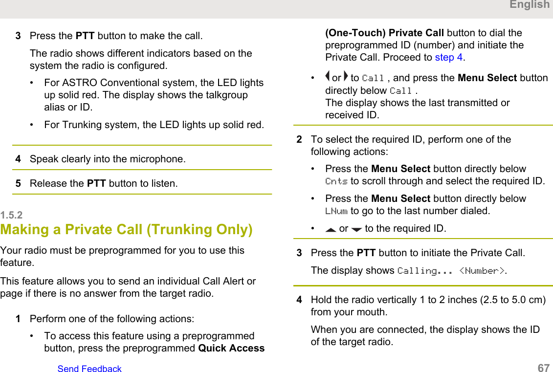
NOTICE:With the inactivity timer enabled (optional), if there isno response to the call after the timer expires, yourradio exits the call with Menu Inactive Exit tone.When you receive a Telephone Call, you hear a telephone-type ringing and the LED blinks green. The backlight of thescreen and the bar turns green.The display shows Phonecall and the call received icon blinks.1Press the Call Response button within 20 secondsafter the call indicators begin.2Press and hold the PTT button to talk. Release thePTT button to listen.3Press   or the Call Response button to hang upand return to the Home screen.See also Making a Telephone Call (Trunking Only) on page69 for details on making a Telephone Call.1.5Methods to Make a Radio CallYou can select a zone, channel, subscriber ID, or talkgroupby using:• The preprogrammed Zone switch.• The 16-Position Select Channel Knob.• A preprogrammed One Touch Call button.• The Contacts list (see Viewing Details of a Contact onpage 82).NOTICE:The radio automatically exits the feature, if thefeature inactivity timer is enabled, when the radio isleft idle and the timer expires. You will hear theMenu Inactive Exit Tone upon feature exit.1.5.1Making a Talkgroup Call To make a call to a group of users, your radio must beconfigured as part of that talkgroup.1Turn the 16-Position Select Channel Knob toselect the channel with the desired talkgroup.2Hold the radio vertically 1 to 2 inches (2.5 to 5.0 cm)from your mouth.English66   Send Feedback
3Press the PTT button to make the call.The radio shows different indicators based on thesystem the radio is configured.• For ASTRO Conventional system, the LED lightsup solid red. The display shows the talkgroupalias or ID.• For Trunking system, the LED lights up solid red.4Speak clearly into the microphone.5Release the PTT button to listen.1.5.2Making a Private Call (Trunking Only)Your radio must be preprogrammed for you to use thisfeature.This feature allows you to send an individual Call Alert orpage if there is no answer from the target radio.1Perform one of the following actions:• To access this feature using a preprogrammedbutton, press the preprogrammed Quick Access(One-Touch) Private Call button to dial thepreprogrammed ID (number) and initiate thePrivate Call. Proceed to step 4.•  or   to Call , and press the Menu Select buttondirectly below Call .The display shows the last transmitted orreceived ID.2To select the required ID, perform one of thefollowing actions:• Press the Menu Select button directly belowCnts to scroll through and select the required ID.• Press the Menu Select button directly belowLNum to go to the last number dialed.•  or   to the required ID.3Press the PTT button to initiate the Private Call.The display shows Calling... <Number>.4Hold the radio vertically 1 to 2 inches (2.5 to 5.0 cm)from your mouth.When you are connected, the display shows the IDof the target radio.EnglishSend Feedback   67
If no acknowledgment is received, the display showsNo acknowledge.5Press and hold the PTT button to talk. Release thePTT button to listen.6Press   to return to the Home screen.1.5.3Making an Enhanced Private Call(Trunking Only)Your radio must be preprogrammed to allow you to use thisfeature.This feature allows you to send an individual Call AlertPage if there is no answer from the target radio. See Sending a Call Alert Page on page 87 for moreinformation.1Perform one of the following actions:• To access this feature using a preprogrammedbutton, press the preprogrammed Quick Access(One-Touch) Enhanced Private Call button todial the preprogrammed ID (number) and initiatethe Private Call. Proceed to step 4.•  or   to Call, and press the Menu Select buttondirectly below Call.The display shows the last transmitted orreceived ID.2To select the required ID, perform one of thefollowing actions:• Press the Menu Select button directly belowCnts to scroll through and select the required ID.• Press the Menu Select button directly belowLNum to go to the last number dialed.•  or   to the required ID.3Press the PTT button to initiate the Private Call.The display shows Calling... <Number>.4Hold the radio vertically 1 to 2 inches (2.5 to 5.0 cm)from your mouth.When you are connected, the display shows the IDof the target radio.English68   Send Feedback
If no acknowledgment is received, the display showsNo acknowledge.If the target radio does not respond before the timeout, the display shows No answer.5Press and hold the PTT button to talk. Release thePTT button to listen.6Press   to return to the Home screen.1.5.4Making a Telephone Call (TrunkingOnly)This feature allows you to make calls similar to standardphone calls to a mobile or landline phone.1Perform one of the following actions:• To access this feature using a preprogrammedbutton, press the preprogrammed Quick Access(One-Touch) Phone Call button to dial thepreprogrammed phone number. Proceed to step4.• or   to Phon, and press the Menu Select buttondirectly below Phon.The display shows the last transmitted orreceived ID.2To select the required ID, perform one of thefollowing actions:• Press the Menu Select button directly belowCnts to scroll through and select the required ID.• Press the Menu Select button directly belowLNum to go to the last number dialed.•  or   to the required phone number.3Press the PTT button to dial the phone number.4Hold the radio vertically 1 to 2 inches (2.5 to 5.0 cm)from your mouth.5When your call is answered, press and hold the PTTbutton to talk. Release the PTT button to listen.6Press   to return to the Home screen.See Phone Call Displays and Alerts on page 59 for moreinformation if your call is not answered.EnglishSend Feedback   69
1.6Switching Between Repeater orDirect Operation ButtonThe Repeater Operation increases the radio coverage areaby connecting with other radios through a repeater. Thetransmit and receive frequencies are different.The Direct or “talkaround operation” allows you to bypassthe repeater and connect directly to another radio. Thetransmit and receive frequencies are the same.Perform one of the following actions:• Press the preprogrammed Repeater/Directswitch to toggle between talkaround and repeatermodes.•  or   to Dir and press the Menu Select buttondirectly below Dir.The display shows Repeater mode if the radio is currentlyin Repeater mode.The display shows Direct mode and the Talkaround icon ifthe radio is currently in Direct mode (during conventionaloperation only).1.7Monitor FeatureThe monitor feature is used to make sure that a channel isclear before transmitting.The lack of static on a digital channel when the usersswitch from analog to digital radios is not an indication thatthe radio is malfunctioning.Digital technology quiets the transmission by removing thenoise from the signal and allows only the clear voice ordata information to be heard.1.7.1Monitoring a ChannelDo one of the followings to monitor a channel. You can usethese options interchangeably depending on yourpreference and the programmed functions.• Monitoring a Channel with Volume Set button.a. Select the desired zone and channel.b. Press and hold the Volume Set button to hearthe volume set tone.c. Adjust the Volume Control Knob if necessary.English70   Send Feedback
d. Release the Volume Set button.e. Press and hold the PTT button to transmit.The LED lights up solid red.f. Release the PTT button to receive (listen).• Monitoring a Channel with Monitor button.a. Press the preprogrammed Monitor button.b. Adjust the Volume Control Knob if necessary.c. Press and hold the PTT button to transmit.The LED lights up solid red.d. Release the PTT button to receive (listen).The Carrier Squelch indicator appears on thedisplay when you monitor a channel using thepreprogrammed Monitor button.• Monitoring a Channel using the selected zonechannel.a. Select the desired zone and channel.b. Listen for a transmission.c. Adjust the Volume Control Knob if necessary.d. Press and hold the PTT button to transmit.The LED lights up solid red.e. Release the PTT button to receive (listen).1.7.2Monitoring Conventional ModeYour radio may be preprogrammed to receive Private-Line®(PL) calls.1Momentarily press the Monitor button to listen foractivity.The Carrier Squelch indicator appears on thedisplay.2Press and hold the Monitor button to set continuousmonitor operation.The duration of the button press is programmable.3Press the Monitor button again, or the PTT button,to return to the original squelch setting.If you try to transmit on a receive-only channel, youhear an invalid tone until you release the PTT button.EnglishSend Feedback   71
EnglishThis page intentionally left blank.72
Advanced FeaturesThis chapter explains the operations of the featuresavailable in your radio.2.1Advanced Call FeaturesThis chapter explains the operations of the call featuresavailable in your radio.2.1.1Selective Call (ASTRO ConventionalOnly)A Selective Call is a call from an individual radio to anotherindividual radio with privacy.2.1.1.1Receiving a Selective CallWhen you receive a Selective Call, the radio indicates oneof the followings:• You hear two alert tones and the LED lights up solidyellow to indicate the transmitting radio is still sendingsignal. The call received icons blinks and the displayshows Call received.• The LED blinks solid green once to indicate thetransmitting radio is pending to receive signal.The speaker unmutes.1Hold the radio vertically 1 to 2 inches (2.5 to 5.0 cm)from your mouth.2Press and hold the PTT button to talk. Release thePTT button to listen.2.1.1.2Making a Selective CallYour radio must be preprogrammed for you to use thisfeature.1Perform one of the following actions:• To access this feature by using a preprogrammedbutton, press the preprogrammed Quick Access(One-Touch) Selective Call button to dial thepreprogrammed ID. Proceed to step 3.EnglishSend Feedback   73
•  or   to Call, and press the Menu Select buttondirectly below Call.The display shows the last transmitted orreceived ID.2To select the required ID, perform one of thefollowing actions:• Press the Menu Select button directly belowCnts to scroll through and select the required ID.• Press the Menu Select button directly belowLNum to go to the last number dialed.•  or   to the required ID.3Hold the radio vertically 1 to 2 inches (2.5 to 5.0 cm)from your mouth.4Press and hold the PTT button to start the SelectiveCall.The display shows the ID of the target radio.5Release the PTT button to listen.6Press   to return to the Home screen.2.1.2Talkgroup Call Feature (ConventionalOperation Only)This feature allows you to define a group of conventionalsystem users so that they can share the use of aconventional channel.NOTICE:Encryption keys are associated to talkgroups. Whentalkgroups are associated, encryption keys arechanged by changing the active talkgroup. See Secure Operations on page 115 for moreinformation.2.1.2.1Selecting a Talkgroup1 or   to Tgrp and press the Menu Select buttondirectly below Tgrp.The display shows the last Talkgroup that wasselected and stored.2Perform one of the following actions:English74   Send Feedback
•  or   to Preset for the preset preprogrammedTalkgroup.•  or   to the required Talkgroup.3Press the Menu Select button directly below Sel tosave the currently selected Talkgroup and return tothe Home screen.If the encryption key associated to the newTalkgroup is erased, you hear a momentary key failtone and the display shows Key fail.If the encryption key that is associated to the newTalkgroup is not allowed, you hear a momentary keyfail tone and the display shows Illegal key.4Press   to return to the Home screen.2.1.3Sending a Status CallThis feature allows you to send data calls to the dispatcherabout a predefined status.Each status can have up to a 14-character name. Amaximum of eight status conditions is possible.NOTICE:The radio automatically exits the feature, if thefeature inactivity timer is enabled. You will hear theMenu Inactive Exit Tone upon feature exit.1Perform one of the following actions:• Press the preprogrammed Status button.•  or   to Sts and press the Menu Select buttondirectly below Sts.The display shows the last acknowledged status call,or the first status in the list.2 or   to the required status.3Press the PTT button to send the status.When the dispatcher acknowledges, you hear fourtones and the display shows Ack received. Theradio returns to normal dispatch operation.If no acknowledgment is received, you hear a low-pitched tone and the display shows Noacknowledge.4Press   to return to the Home screen.EnglishSend Feedback   75
No traffic is heard on trunked channels while StatusCalls is selected. If the radio detects no Status Callactivity for six seconds, an alert tone sounds untilyou press   or the PTT button.2.1.4Responding to the DynamicRegrouping Feature (Trunking Only)This feature allows the dispatcher to temporarily reassignselected radios to a particular channel where they cancommunicate with each other. This feature is typically usedduring special operations and is enabled by a qualifiedradio technician.You will not notice whether your radio has this featureenabled until a dynamic regrouping command is sent bythe dispatcher.NOTICE:If you try to access a zone or channel that has beenreserved by the dispatcher as a dynamicallyregrouped mode for other users, you hear an invalidtone.When your radio is dynamically regrouped, it automaticallyswitches to the dynamically regrouped channel. You hear aGurgle tone and the display shows the dynamicallyregrouped channel’s name.Press the PTT button to talk. Release PTT button tolisten.When the dispatcher cancels dynamic regrouping, the radioautomatically returns to the zone and channel that youwere using before the radio was dynamically regrouped.2.1.4.1Requesting a Reprogram (Trunking Only)This feature allows you to notify the dispatcher when youwant a new dynamic regrouping assignment.Perform one of the following actions:• Press the preprogrammed Reprogram Requestbutton to send reprogram request to thedispatcher.English76   Send Feedback
•  or   to Rpgm then press the Menu Select buttondirectly below Rpgm to send reprogram request tothe dispatcher.The display shows Reprogram Rqst and Pleasewait.If you hear five beeps, the dispatcher has acknowledgedthe reprogram request. The display shows Ack receivedand the radio returns to the Home screen.If the dispatcher does not acknowledge the reprogramrequest within six seconds, you hear a low-pitched alerttone and the display shows No acknowledge. Try again orpress   to cancel and return to the Home screen.2.1.4.2Classification of Regrouped RadiosThe dispatcher can classify regrouped radios into either oftwo categories:Select EnabledSelect-enabled radios are free to change to anyavailable channel, including the dynamic-regroupingchannel, once the user has selected the dynamic-regrouping position.Select DisabledSelect-disabled radios cannot change channels whiledynamically regrouped. The dispatcher has forced theradio to remain on the dynamic-regrouping channel.The Scan or Private Call feature cannot be selected whileyour radio is Select Disabled.2.1.5Dynamic Zone Programming (DZP)NOTICE:Your radio must be preprogrammed to allow you touse this feature. This feature works on the conditionat least one zone in the radio must be a non-dynamic zone.This feature provides one or more Dynamic Zones to storefrequently used channels be it conventional or trunking.These dynamic channels are saved from pre-existing (non-dynamic) channels in the radio. This saves the time andeffort from the regular navigation around the working zonesand channels. User can also delete or update the list in theDynamic Zone.EnglishSend Feedback   77
2.1.5.1Entering the Dynamic Zone to Select aDynamic Channel1 or   to Zone then press the Menu Select buttondirectly below Zone.The display shows the Zone screen.2 or   to <# Dynamic Zone Channels>.23Perform one of the following actions:• Press the Menu Select button below Sel toselect.• Press the Menu Select button below Exit to exit.If you have selected one of the Dynamic ZoneChannels list, the display returns to Home screenwith the selected <# Dynamic Zone Channels>shown on the screen.2If you have selected Exit without selecting anyDynamic Zone Channels list, the display returns toHome screen without any changes.2.1.5.2Saving a Channel in the Dynamic Zonefrom List SelectionThe radio must be in Dynamic Zone in order to perform thisoperation.1 or   to ZnPr. Press the Menu Select button directlybelow ZnPr to enter Program Zone screen.2Press the Menu Select button directly below Edit.The display shows Search Options screen.3 or   to List Selection. Press the MenuSelect button directly below Sel .The display shows Select Zone screen.2# indicates number of the channel on the 16-Position Switch which are numbered from 1 to 16.English78   Send Feedback
4 or   to the required zone. Press the MenuSelect button directly below Sel .The display shows Select Chan screen.5 or   to the required channel. Press the MenuSelect button directly below Sel .The display shows Channel updated.6Press the Menu Select button directly below Exit toreturn to Home screen.2.1.5.3Deleting a Channel in the Dynamic ZoneThe radio must be in Dynamic Zone in order to perform thisoperation.1 or   to ZnPr then press the Menu Select buttondirectly below ZnPr to enter Program Zone screen.The display shows the dynamic channels list.2 or   to the saved dynamic channel then pressthe Menu Select button directly below Del.The display shows Channel deleted screen.3Press the Menu Select button below Exit to returnto Home screen.The Home screen shows <Dynamic ZoneChannels>.If the channel deleted is the Home channel, theHome screen shows <Zone Name>“Blank”.2.2ContactsThis feature provides “address-book” capabilities on yourradio. Each entry corresponds to an alias (name) or ID(number) that you use to initiate a call.Contact entries are alphabetically sorted according to entryalias. Each alias can have up to five IDs of different calltypes associated with it.Additionally, each entry, depending on context(conventional, trunking, or phone), associates with one orEnglishSend Feedback   79
more of the four types of calls: Phone Call, Selective Call,Private Call, or Call Alert.Each entry within Contacts contains the followinginformation:• Call Alias (Name)• Call ID (Number)• Call Type (Icon)• WACN ID (Astro 25 Trunking IDs only)• System IDNOTICE:Your radio must be preprogrammed to allow you toadd, edit, or delete the contact entries.Your radio also supports a maximum of 50 call lists. Eachlist can store up to 100 IDs (numbers).NOTICE:Your radio is preprogrammed with a number ofcontacts per Call Lists. Check with your dealer orsystem administrator for more information.The radio automatically exits the feature, if thefeature inactivity timer is enabled, when the radio isleft idle and the timer expires. You hear the MenuInactive Exit Tone upon feature exit.2.2.1Making a Private Call from ContactsYour radio must be preprogrammed to allow you to use thisfeature.1 or   to Cnts and press the Menu Select buttondirectly below Cnts.The entries are alphabetically sorted.2 or   to the required subscriber alias.3Press the Menu Select button directly below Optnand proceed to the next step.4 or   to Call and press the Menu Select buttondirectly below Sel.5 or   to select the call type.6Hold the radio vertically 1 to 2 inches (2.5 to 5.0 cm)from your mouth.English80   Send Feedback
7Press the PTT button to initiate the call.During the call, the display shows the subscriberalias.8Press and hold the PTT button to talk. Release thePTT button to listen.The LED lights up solid red when the PTT button ispressed.If there is no voice activity for a preprogrammed period oftime, the call ends.If the call reaches the maximum ring time, the call ends.2.2.2Adding a Contact to a Call List1 or   to Cnts and press the Menu Select buttondirectly below Cnts .The entries are alphabetically sorted.2 or   to the entry you want to add and press theMenu Select button directly below Optn .3 or   to Add to CallLst and press the MenuSelect button directly below Sel .4Perform one of the following actions:•  or   to the required Call List and press theMenu Select button directly below Add to add tothe Call List.•  or   to Cncl to cancel and return to the mainscreen of Contacts.The display shows Please wait momentarily beforeshowing <Entry> added to Call List,confirming the addition of the contact to the list.The radio returns to the main display of Contacts.2.2.3Removing a Contact from a Call List1 or   to Cnts and press the Menu Select buttondirectly below Cnts .The entries are alphabetically sorted.EnglishSend Feedback   81
2 or   to the entry you want to delete and pressthe Menu Select button directly below Optn .3 or   to Rm frm CallLst and press the MenuSelect button directly below Sel .The display shows Remove <Entry> frm CallList?.4Press the Menu Select button directly below Yes toremove the entry from the Call List, or No to canceland return to the main display of Contacts.The display shows Please wait momentarily beforeshowing <Entry> removed from Call List,confirming the removal of the contact from the list.The radio returns to the main display of Contacts.2.2.4Viewing Details of a Contact1 or   to Cnts and press the Menu Select buttondirectly below Cnts .The entries are alphabetically sorted.2 or   to the entry you want to view and press theMenu Select button directly below Optn .3 or   to View and press the Menu Select buttondirectly below Sel .The display shows all the numbers associated with theentry.2.3Scan ListsScan lists are created and assigned to individual channels/groups. Your radio scans for voice activity by cyclingthrough the channel/group sequence specified in the scanlist for the current channel/group.Your radio supports different types of Scan Lists:• Trunking Priority Monitor Scan List• Conventional Scan List• Talkgroup Scan ListPlease refer to a qualified radio technician for the maximumnumber of Scan Lists can be programmed in your radio.These lists must be preprogrammed by a qualified radiotechnician.English82   Send Feedback
2.3.1Viewing a Scan List1 or   to ScnL and press the Menu Select buttondirectly below ScnL .2 or   to view the members on the list.3Press   to exit the current display and return to theHome screen.2.3.2Editing the Scan ListThis feature allows you to change scan list members andpriorities.1Perform one of the following actions:• Long press the preprogrammed Scan ListProgramming button (side button).• or   to ScnL then press the Menu Select buttondirectly below ScnL .The display shows the lists that can be changed.2 or   to the entry you want to edit.3Perform one of the following actions:• Press the Menu Select button directly below Selto add and/or change the priority of the currentlydisplayed channel in the scan list.• Press the Menu Select button directly below Delto delete the currently displayed channel from thescan list.• Press the Menu Select button directly below Rclto view the next member of the scan list.4Perform one of the following actions to selectanother channel that needs to be added or deletedthen repeat step 3. Otherwise, proceed to the nextstep.•  or   to the desired channel.• Use the 16-Position Select knob to select thechannel.5Perform one of the following actions:• Move the Scan List Programming switch out ofprogramming position.EnglishSend Feedback   83
• Press   to exit scan list programming and returnto the Home screen.See Viewing and Changing the Priority Status on page 84for more information on how to add and/or change thepriority of the currently displayed channel in the scan list.2.3.3Changing the Scan List Status1Perform one of the following actions:• Long press the preprogrammed Scan ListProgramming button (side button).• Move the preprogrammed Scan ListProgramming switch to programming position.The display shows the programming mode icon andthe first list member.2 or   to the member you want to edit.3Perform one of the following actions:• Press the Select button once to add the currentlydisplayed channel to the scan list.• Press the Select button one or more times tochange the scan list status icon of the currentlydisplayed channel.4Perform one of the following actions:•  or   to select more list members whose scanstatus you want to change.• Use the 16-Position Select knob to selectanother scan list member.5Move the Scan List Programming switch out ofprogramming position. Press   to exit scan listprogramming and return to the Home screen.2.3.4Viewing and Changing the PriorityStatusPerform one of the following actions:• Press the Menu Select button directly below Selone or more times to change the priority status ofthe current displayed channel.English84   Send Feedback
• Press the Select button one or more times totoggle between different status of the Scan Liststatus icon of the current displayed channel.The radio shows one of following priority status iconsand scenarios:• A Scan icon indicates that the current channel isin the scan list as a non-priority channel. TheLED lights up solid green.• A Priority-One Channel Scan icon indicates thatthe current channel is in the scan list as thePriority-One channel. The LED rapidly blinksgreen. You hear all traffic on the Priority-Onechannel, regardless of traffic on non-prioritychannels.• A Priority-Two Channel Scan icon indicates thatthe current channel is in the scan list as thePriority-Two channel. The LED blinks green.• No icon indicates that the current channel isdeleted from the scan list.2.4ScanThis feature allows you to monitor traffic on differentchannels by scanning a preprogrammed list of channels.2.4.1Turning Scan On or OffPerform one of the following actions:• Press the preprogrammed Scan button to toggleScan On or Scan Off to initiate or stop scan.• Turn the preprogrammed Scan switch to theScan on or Scan off position to initiate or stopscan.• or   to Scan and press the Menu Select buttondirectly below Scan.If the scan is enabled, the display shows Scan onand the scan status icon.If the scan is disabled, the display shows Scan Off.The radio returns to the Home screen.EnglishSend Feedback   85
2.4.2Making a Dynamic Priority Change(Conventional Scan Only)While the radio is scanning, the dynamic priority changefeature allows you to temporarily change any channel in ascan list (except for the Priority-One channel) to thePriority-Two channel.This change remains in effect until scan is turned off. Scanthen reverts to the preprogrammed (original) setting.• Making a Dynamic Priority Change using thepreprogrammed Dynamic Priority button:a. When the radio locks onto the channeldesignated as the new Priority-Two channel,press the preprogrammed Dynamic Prioritybutton.The radio continues scanning the remainingchannels in the list.2.4.3Deleting a Nuisance ChannelIf a channel continually generates unwanted calls or noise(termed “nuisance” channel), you can temporarily removethe unwanted channel from the scan list.This capability does not apply to priority channels or thedesignated transmit channel.When the radio is locked onto the channel to bedeleted, perform one of the following actions:• Press the preprogrammed Nuisance Deletebutton.•  or   to Nuis and press the Menu Select buttondirectly below Nuis.The radio continues scanning the remaining channels inthe list.2.4.4Restoring a Nuisance ChannelTo restore the deleted nuisance channel, performone of the following actions:• Stop and restart a scan.English86   Send Feedback
• Mode change to another channel and back to theoriginal channel.• Turn off the radio and then turn it on again.Nuisance mode delete can be disabled by thesystem administrator.2.5Call Alert PagingThis feature allows your radio to work like a pager.Even if other users are away from their radios, or if they areunable to hear their radios, you can send them anindividual Call Alert page. You can also verify if a radio isactive on the system.Depending on how your radio is programmed, when youmake an Enhanced Private Call, the radio eitherautomatically sends a call alert page if there is no answerafter the maximum ring time, or when you press the PTTbutton.NOTICE:This feature must be preprogrammed by a qualifiedradio technician.2.5.1Receiving a Call Alert PageWhen you receive a Call Alert page, you hear fourrepeating alert tones and the LED blinks green. The callreceived icons blinks and the display shows Pagereceived.Press any button to clear the Call Alert page.See Making a Talkgroup Call on page 66 or Making aPrivate Call (Trunking Only) on page 67 for moreinformation on returning the call.2.5.2Sending a Call Alert PageDo one of the following to send a call alert page:NOTICE:If the feature inactivity timer is enabled, your radioautomatically exits the feature when your radio isleft idle long enough for the time to expire. You hearthe Menu Inactive Exit Tone upon feature exit.• Sending a call alert page using the preprogrammedQuick Access (One-Touch) Call Alert Pagingbutton:EnglishSend Feedback   87
a. Press the preprogrammed Quick Access (One-Touch) Call Alert Paging button to send a pageto the preprogrammed ID.The display shows Paging...<Number>.If the call alert page is sent successfully, you heara tone and the display shows Ack received.The radio returns to the Home screen.If the call alert page is not acknowledged, youhear a low tone and the display shows Noacknowledge. Press the Menu Select buttondirectly below Ok to return to the main screen forContacts.• Sending a call alert page using the radio menuPage :a.  or   to Page .b. Press the Menu Select button directly belowPage .c. Press the Menu Select button directly belowCnts to view the required ID,   or   to therequired ID.d. Press the PTT button to send the page.The display shows Paging...<Number>.If the call alert page is sent successfully, you heara tone and the display shows Ack received.The radio returns to the Home screen.If the call alert page is not acknowledged, youhear a low tone and the display shows Noacknowledge. Press the Menu Select buttondirectly below Ok to return to the main screen ofContacts.• Sending a call alert page using the radio menuCall :a.  or   to Call .b. Press the Menu Select button directly belowCall .c.  or   to select the alias or ID, and press thePTT button to initiate the call.If the target radio does not respond after apreprogrammed period of time, the display showsSend page?.English88   Send Feedback
d. To send the call alert page, press the MenuSelect button directly below Yes . To exit thescreen without sending the call alert page, pressthe Menu Select button directly below No .The display shows Paging...<Alias>.If the call alert page is sent successfully, you heara tone and the display shows Ack received.The radio returns to the Home screen.If the call alert page is not acknowledged, youhear a low tone and the display shows Noacknowledge. Press the Menu Select buttondirectly below Ok to return to the main screen ofContacts.2.6Emergency OperationThe Emergency feature is used to indicate a criticalsituation.If the Top (Orange) button is preprogrammed to send anemergency signal, this signal overrides any othercommunication over the selected channel.Your radio supports the following Emergency modes:• Emergency Alarm• Emergency Call (Trunking Only)• Emergency Alarm with Emergency Call• Silent Emergency AlarmCheck with your dealer or system administrator for moreinformation on the programming of this feature.Each channel can only assigned one of the Emergencymodes above. The radio responds differently whenpressing the preprogrammed Emergency button in eachchannel.EnglishSend Feedback   89
NOTICE:To exit emergency at any time, press and hold thepreprogrammed Emergency button for about asecond. This timer is programmable from 0–6250milliseconds by a qualified technician.The radio operates in the normal dispatch mannerwhile in Emergency Call, except if enabled, itreturns to one of the following:Tactical/Non-RevertThe radio sends emergency alarm and/or makeemergency call on the current selected channel.Non-Tactical/Revert for Conventional systemThe radio reverts to the preprogrammedemergency channel to send alarm and/or makeemergency call.Non-Tactical/Revert for Trunking systemThe radio reverts to the preprogrammedemergency talkgroup to send alarm and/or makeemergency call.Man Down is an alternate way to activate the Emergencyfeature on the condition the Emergency must be set up forthis feature to operate.See Man Down on page 100 for details.2.6.1Sending an Emergency AlarmThis feature allows you to send a data transmission, whichidentifies the radio sending the emergency, to thedispatcher.NOTICE:The default timer of Emergency button press toactivate Emergency is 50 milliseconds. This timer isprogrammable from 50–6200 milliseconds by aqualified technician.Press the preprogrammed Emergency button.One of the following scenarios occurs:• The display shows Emergency on the currentzone and channel. You hear a short medium-pitched tone and the LED blinks red momentarily.• The radio sounds a short low-pitched tone toindicate that the selected channel does notsupport emergency and rejects to launchemergency mode.When you receive the dispatcher’s acknowledgment, thedisplay shows Ack received. Four tones sound, the alarmends, and the radio exits the Emergency Alarm mode.English90   Send Feedback
If no acknowledgment is received, the display shows Noacknowledge. The alarm ends when the timer expires andthe radio exits the Emergency Alarm mode.2.6.2Sending an Emergency Call (TrunkingOnly)This feature gives your radio priority access to a talkgroup.1Press the preprogrammed Emergency button.One of the following scenarios occurs:• The display shows Emergency on the currentzone and channel. You hear a short medium-pitched tone and the LED blinks red momentarily.• You hear the radio sounds a short low-pitchedtone to indicate the selected channel does notsupport emergency and rejects to launchemergency mode.2Hold the radio vertically 1 to 2 inches (2.5 to 5.0 cm)from your mouth.3Press and hold the PTT button. Speak clearly intothe microphone.4Release the PTT button to end the transmission andwait for a response from the dispatcher.5To exit Emergency Call, press and hold thepreprogrammed Emergency button for about asecond.2.6.3Sending An Emergency Call With HotMic (Trunking Only)This feature allows you to send an Emergency Call with hotmic to a group of radios.Your radio must be programmed for this type of operation.Your radio microphone is automatically activated, allowingyou to communicate with the group of radios withoutpressing the PTT button. This activated microphone state isalso known as hot mic. The hot mic applies to the first voicetransmission from your radio during the Emergency call.For subsequent transmissions in the same Emergency call,you must press the PTT button.EnglishSend Feedback   91
Follow the procedure to send Emergency Call with hot micon your radio.1Press the preprogrammed Emergency button.One of the following scenarios occurs:• The display shows Emergency on the currentzone and channel. A tone sounds and the LEDblinks red momentarily.• A tone sounds to indicate the selected channeldoes not support emergency and rejects tolaunch emergency mode.2Hold the radio vertically 1 to 2 inches (2.5 to 5.0 cm)from your mouth.3The microphone remains active for the hot mic timespecified in the radio's codeplug programming.4To exit Emergency Call, press and hold thepreprogrammed Emergency button.2.6.4Sending an Emergency Alarm withEmergency CallThis feature gives your radio priority access on a channelfor conventional system, and to a talkgroup for trunkingsystem.1Press the preprogrammed Emergency button.If successful, the display shows Emergency on thecurrent zone and channel. You hear a short,medium-pitched tone and the LED blinks redmomentarily.The radio exits Emergency Alarm and enters theEmergency Call state when one of the followingscenarios occur:• You receive the dispatcher acknowledgment. Thedisplay shows Ack received.• You receive no acknowledgment. The displayshows No acknowledge.• You press the PTT button while in the EmergencyAlarm mode.If unsuccessful, you hear the radio sounds a shortlow-pitched tone to indicate the selected channelEnglish92   Send Feedback
does not support emergency and rejects to launchemergency mode.2Hold the radio vertically 1 to 2 inches (2.5 to 5.0 cm)from your mouth.3Press and hold the PTT button. Speak clearly intothe microphone.4Release the PTT button to end the transmission andwait for a response from the dispatcher.5To exit Emergency Call, press and hold thepreprogrammed Emergency button for about asecond.Turning off the radio also cancels the emergencystate.2.6.5Sending An Emergency Alarm and Callwith Hot MicThis feature allows you to send an Emergency Alarm andCall with hot mic to a group of radios.Your radio must be programmed for this type of operation.Follow the procedure to send Emergency Alarms and Callwith hot mic on your radio.1Press the preprogrammed Emergency button.If successful, the display shows Emergency on thecurrent zone and channel. A tone sounds and theLED blinks red momentarily.The radio exits Emergency Alarm and enters theEmergency Call state when one of the followingscenarios occur:• You receive the dispatcher acknowledgment. Thedisplay shows Ack received.• You receive no acknowledgment. The displayshows No acknowledge.If unsuccessful, a tone sounds to indicate theselected channel does not support emergency andrejects to launch emergency mode.2Hold the radio vertically 1 to 2 inches (2.5 to 5.0 cm)from your mouth.EnglishSend Feedback   93
3The microphone remains active for the hot mic timespecified in your radio's codeplug programming.4To exit Emergency Call, press and hold thepreprogrammed Emergency button.Turning off the radio also cancels the emergencystate.2.6.6Sending a Silent Emergency AlarmThis feature allows you to send an Emergency Alarm to thesystem without triggering any audio or visual indicators.1Press the preprogrammed Emergency button.The display shows no changes, the LED does notlight up, and you hear no tones. The silentemergency state continues until you perform thenext step.2Perform one of the following actions:• Press and hold the preprogrammed Emergencybutton for about a second to exit the SilentEmergency Alarm mode.• Press and release the PTT button to exit theSilent Emergency Alarm mode and enter regulardispatch or Emergency Call mode.2.6.7Change of Channels during EmergencyFor ALL Emergency transmissions, when changingchannels:• If the new channel is also preprogrammed forEmergency, you can change channels while inEmergency operation. The emergency alarm or callcontinues on the new channel.• If the new channel is not preprogrammed forEmergency, the display shows No emergency, and youhear an invalid tone until you exit the Emergency stateor change to a channel preprogrammed for Emergency.2.6.8Emergency Keep-Alive FeatureThis feature, when enabled, prevents the radio from beingturned off by using the On/Off Control Knob when theradio is in the Emergency state.English94   Send Feedback
NOTICE:The radio only exits the Emergency state using oneof the ways mentioned in the previous sections.See Sending an Emergency Alarm on page 90, Sending an Emergency Call (Trunking Only) onpage 91, Sending an Emergency Alarm withEmergency Call on page 92, or Sending a SilentEmergency Alarm on page 94.2.6.9Emergency Find MeThe Emergency Find Me (EFM) feature is an additionalemergency feature providing information to nearby radios,utilizing the Bluetooth Low Energy (BT-LE) transmissionfrom a radio. In an emergency situation, when the userpresses the pre-programmed Emergency button, there willbe periodic EFM beacon transmitted from the radio alongwith the other existing emergency activities. The radioswhich are near to the transmitting radio and are capable ofreceiving BT-LE signals would receive the beacontransmission. The range of EFM beacon depends on theenvironment in which the radios are located.Check with your dealer or system administrator for moreinformation on the programming of this feature.2.6.9.1Sending and Receiving Emergency FindMe Beacon1Press the pre-programmed Emergency button totransmit the EFM beacon.The receiving radio displays Beacon RX and thetransmitting radio Contact ID or alias on the radiodisplay. In the case of multiple radios transmitting atone time, the receiving radio displays MultipleBeacon RX.2Press the menu Bcon. The receiving radio displaysthe transmitting radios Contact ID and one of thefollowing RSSI values based on the signal strengthreceived:• RSSI-Excellent• RSSI-Good• RSSI-Fair• RSSI-PoorEnglishSend Feedback   95
NOTICE:RSSI-Poor will be shown if the distancebetween transmit radio and receive radiosare more than 8 to 10 meters in an openenvironment.2.7FiregroundThe portable Fireground Communications System isdesigned for deployment at an incident scene. It consists ofcentral components:• Your APX portable radios• Incident Management Software• Command Terminal• Radio Frequency (RF) Modem (Conventional Only)• Control Channel Radio (Trunking)• Optional Data Radio (Trunking)• Accountability Server (Trunking)• DVRS (Optional)These components provide on-scene and inbuilding radiocoverage, and enhanced personnel accountability andmonitoring.The radio helps to indicate your presence on the scene if itis in the range of the Incident Commander commandterminal, or trunking radio system.Each Fireground Communication System radioautomatically reports your radio ID on the commandermobile command terminal. Your name, riding position andsector are all can be configured to be seen at theCommander’s command terminal.If you have a critical situation, you can press theEmergency button which activates an alarm on the IncidentManagement Software at the command terminal.The command terminal receives the following statusupdates from your radio:• Powering up or down the radio• Automatic response to Polling• Response to Evacuation commands• Pressing the PTT button to make voice transmission• Sending an Emergency Alarm and Call• Entering or Exiting a Trunking TalkgroupEnglish96   Send Feedback
2.7.1Entering Fireground Zone Channel(Conventional)1Upon powering up, one of the following scenariosoccurs:• If the Fireground Zone Channel is set as default,you hear the gurgle tone and the radio displaysthe home screen. You are in Fireground zonechannel.• If the Fireground Zone Channel is set as default,but you hear a short, low-pitched tone, thedisplay shows Reg failed to indicate that thecommand terminal does not respond toFireground Zone Channel. Get a qualifiedtechnician for assistance.• If your home channel is not Fireground ZoneChannel, toggle or change the radio zonechannel to Fireground Zone Channel.If you are entering Fireground Trunking Talkgroup,upon powering up, ensure that the FiregroundTrunking Talkgroup is selected. The subscriber unitautomatically appears on the Incident Commander'sterminal.2Listen for a transmission. Adjust the VolumeControl Knob if necessary.3Perform one of the following actions:• Press and hold the preprogrammed Volume Setbutton to hear the volume set tone. Adjust theVolume Control Knob if necessary. Release theVolume Set button.• At the desired Fireground zone and channel,press the preprogrammed Monitor button andlisten for activity. Adjust the Volume ControlKnob if necessary.• If your radio is working in Fireground ZoneChannel, proceed to next step.4Press and hold the PTT button to transmit. The LEDlights up solid red while transmitting. Talk into themicrophone clearly if needed.5Release the PTT button to receive.You hear a Transmit End Tone.EnglishSend Feedback   97
2.7.2Sending Evacuation ToneThis feature enables the evacuation tone to be heard onthe transmitting radio and on any radio that is able toreceive the tone instruction.Press and hold the PTT button and then short pressthe Top (Orange) button.Once the tone begins to sound, if the orange button isreleased the tone continues to alarm on all radios within thetalkgroup, until the PTT button is released.NOTICE:Radio does not transmit evacuation tone if the radiois in secure mode.2.7.3Responding to Evacuation IndicatorThe Incident Commander can trigger one of sixteenTactical Alerts from the Command Terminal. These alertscan target individuals or groups of users within theFireground Communication System. The ergonomic (visualand audible) response for the Tactical Alerts can becustomized.Your radio sounds the audible response at the profilemaximum alert tone volume level. The display shows theconfigurable programmed alert text and intelligent lighting.Perform one of the following actions:• Press the radio Top Side button.• Press the RSM Side Button 1 if the radio isconnected to RSM.• Press the PTT button. PTT button must beconfigured in CPS to enable this function.The radio cancels the indications, a tone sounds andthe radio sends an acknowledgment to the commandterminal.NOTICE:Move the Volume Control Knob to adjustthe volume of the audible alert from fullvolume.English98   Send Feedback
2.8Tactical Public Safety (TPS)(Conventional Only)TPS enables the user of a group to identify the start andthe end of a transmission by displaying the caller name orID on the radio display.2.8.1Using TPS Normal TransmissionAt TPS Zone Channel, perform one of the followingactions:• Press PTT button to transmit. Talk clearly into themicrophone. Release PTT button to listen.• Receive and listen to call, the radio displays thecaller’s name or ID.2.8.2Using TPS Emergency TransmissionThe following are two important alert tones designed forthis feature.Emergency BeaconDuring Emergency if the TPS radio user pushes theEmergency button, the radio sounds a Beacon at themaximum volume of the radio at radio’s internal speakerand it is not adjustable. This beacon goes to silent whenuser presses the PTT button for voice transmission.Emergency Call De-Key SidetoneThe radio sounds an alert tone to remind radio user thatthe Emergency Mode is still active after user releasesthe PTT button for an Emergency call transmission. Thevolume of loudness depends on the maximum tone atyour radio profile.1Press the Emergency button to enter EmergencyMode.You hear the Emergency Beacon.2Press PTT button to make an Emergency Call.3Release to listen.You hear Emergency Call De-Key Sidetone. After ashort pause, you hear Emergency Beacon.EnglishSend Feedback   99
4Long press Emergency button to exit Emergencymode and cancel Emergency Beacon.2.9Man DownMan Down condition is determined based upon the radio tiltangle or a combination of radio tilt angle and the lack ofradio motion.Man Down feature is an alternate way to activate theEmergency feature if Emergency has been programmed inyour radio.NOTICE:This feature could be preprogrammed for allchannels that support Emergency feature or couldbe preprogrammed specifically to a zone andchannel which has Emergency feature. Consult youragent or qualified technician for more details.Your radio automatically activates Emergency Alarm or Callwhen the radio achieves or passes a tilt angle threshold ora combination of the angle threshold and radio motionbelow the motion sensitivity level, depending upon how theradio is programmed. The radio must stay in this conditionfor a preprogrammed amount of time before theEmergency Alarm or Call is activated.NOTICE:It is recommended that an Emergency button ispreprogrammed in order to allow the user to exit theemergency condition.The Man Down feature provides a Clear function to theuser. After a Man Down condition has been detected, theuser can press a preprogrammed Clear button orpreprogrammed Menu Select button to cancel the ManDown condition. The radio remains in the Man Down statewithout triggering an emergency condition until the radio ismoved out of the Man Down state, at which point ManDown functionality resumes.The Man Down feature has three phases:1The radio senses the Man Down condition and Pre-AlertTimer is initiated.2Man Down condition continues for the time durationdefined in the Pre-Alert Timer field. At the end of thistime, the radio alerts the user on the Man Down statuswith an audible alert tone and Man-Down text on thescreen. The Post-Alert Timer also initiates at this point.3Man Down condition continues for the time durationdefined in the Post-Alert Timer field. Once the timerexpires, the Emergency alarm is transmitted. The ManEnglish100   Send Feedback
Down Clear function is used in this phase to cancel theMan Down condition.The following scenarios affect the timers:• Pressing the PTT button suspends the Man Downtimers; releasing the PTT button re-initiates the Pre-Alert Timer.• Pressing other buttons on the radio does not impactthese timers.• Repositioning the radio exits the Man Down feature,which stops and resets the timers.• Pressing a preprogrammed Clear button or pressing aMenu Select button preprogrammed for Clear stopsand resets the timers. The timers do not restart until theradio is repositioned.NOTICE:Emergency must be set up for this feature tooperate. For details on operating the Emergencyalerts, please see Emergency Operation on page89.If the radio is preprogrammed to horizontal only, itmust be worn in a vertical position otherwise theMan Down alert may be inadvertently triggered.When the radio is programmed with Man Downfeature, special care is required when charging theradio with a wall mounted charger. See ProperWays to Handle the Radio on page 179 for details.2.9.1Pre-Alert TimerThis timer sets the amount of time that a Man Downcondition must be present before the radio-user is warnedof the Man Down condition.When the radio detects that it has returned to the verticalposition or when the radio detects motion, the Pre-Alerttimer stops and is reset.The Pre-Alert timer reinitiates when the radio detects it is inthe horizontal position or motionless again.EnglishSend Feedback   101
2.9.2Post-Alert TimerThis timer sets the amount of time the radio needs toremain in the Man Down condition before the Emergencyalarm is transmitted. When the Post-Alert Timer is initiated,the radio alerts the user with an audible tone and displaysthe Man-Down text.See Exiting Man Down Feature on page 103 to exit ManDown feature.2.9.3Radio Alerts When Man Down Featureis TriggeredThe Man Down alert tone volume is directly related to theradio speaker volume. Ensure that the radio speakervolume is loud enough so that the user does not miss thePost-Alert tone.NOTICE:If the radio is programmed with Silent Emergency,the radio inhibits the alert tone and visual alertassociated with the emergency feature.If the radio is programmed in Surveillance Mode, theradio inhibits all tones and lights on the radioincluding the Man Down tones.2.9.4Triggering EmergencyWhen the user does not clear the Man Down condition andthe Post-Alert Timer comes to an end, Emergency Alarm orcall is triggered. The radio sends emergency message tounits within the same Talkgroup. The radio also sends IDnumber and GPS coordinates to dispatcher if thesefeatures are enabled. User can exit Emergency followingthe Emergency procedure. See Emergency Operation onpage 89 for details.NOTICE:At this point the Man Down features is complete.Use normal Emergency procedures to cancelEmergency transmissions.English102   Send Feedback
2.9.5Radio Alerts When Man DownEnhanced is TriggeredNOTICE:This feature is to be preprogrammed specifically toa zone and channel which supports Emergencyfeature.The volume and repetition duration of Man DownEnhanced alert tone could be customized andpreprogrammed to suite the required situation.Consult your agent or qualified technician for moredetails.When the radio initiates Man Down Enhanced, you hearthe Critical Man Down Continuous alert tone from the radiospeaker. The volume of this tone is set to the louder of thepreprogrammed minimum level or the current radio speakerlevel. This acts as a beacon to find the radio.NOTICE:If the radio is programmed with Silent Emergency,the radio inhibits the alert tone and visual alertassociated with the emergency feature.If the radio is programmed in Surveillance Mode, thealert tone can be heard from the radio speaker.Once the alert tone is active, changing to another channelwith different setup triggers a different response from theradio as described next.• The alert tone is inhibited when you change to achannel without Emergency feature.• The alert tone is inhibited when you change to achannel with Emergency but no Man Down feature.• The current alert tone is inhibited and is replaced with adifferent alert tone when you change to a channel withEmergency and different Man Down configuration.• The alert tone continues when you change to a channelwith Emergency and similar Man Down configuration.2.9.6Exiting Man Down FeatureIf you are not in a real Man Down situation, you should exitthe Man Down feature and prevent emergency from goingoff with the following operation.Perform one of the following actions:• Repositioning the radio or shaking the radio(when motion sensitivity is enabled).EnglishSend Feedback   103
• Press the preprogrammed Man Down Clearbutton to exit.• Press the Menu Select button below Clr to exit.2.9.7Re-Initiating Man DownAfter exiting the Emergency Operation when the radio isstill in Man Down condition (tilted achieving threshold angleor motionless), user must first exit Man Down condition tothen reinitiate the Man Down feature.Return the radio to the vertical position or shake theradio (when motion sensitivity is enabled).2.9.8Testing the Man Down FeatureEnable the Emergency feature with Silent Alarm disabled,but not in Surveillance Mode before running this test on theradio.1Turn the radio on and place in the vertical position,for at least 5 seconds.2Lay the radio down in the horizontal position.3Wait for alert tone.One of the following scenarios occurs:• The radio alerts with audible tone and displays Man-Down.• If no tone is heard, make sure that the Man Downfeature is enabled on your radio. If Man Down featurewas not enabled, please enable it and repeat step 1 to step 3.• If the Man Down feature is enabled and no tone isheard, send the radio to a qualified technician.2.10Automatic Registration Service(ARS)This feature provides an automated data applicationregistration for the radio. When you turn on the radio, thedevice automatically registers with the server.Data applications within the fixed network can determinethe presence of a device on the system and send data tothe device. For example: Text Messaging Service (TMS).English104   Send Feedback
The ARS for the radio consists of two modes:• ARS Server Mode (default mode)• ARS Non-Server ModeNOTICE:The default ARS mode can be changed by aqualified radio technician using the radio’sprogramming software.2.10.1Selecting or Changing the ARS ModeThe following methods are options on how to select orchange the ARS Mode. The result of all the methods is thesame. You can use the options interchangeably dependingon your preference and the programmed functions.• Selecting or Changing the ARS mode using the 16-Position Select knob:a. Once the zone you want is displayed, turn thepreprogrammed 16-Position Select knob to thedesired mode.• Selecting or Changing the ARS mode using the radiomenu:a.  or   to Chan .b. Press the Menu Select button directly belowChan .The display shows the current channel name.c.  or   to the required channel or mode.One of the following scenarios occur:• In ARS Server Mode, the display shows thezone and ARS server channel.• In ARS Non-Server Mode, the display showsthe zone and ARS non-server channel.• If the channel or mode selected isunprogrammed, the display showsUnprogrammed. Repeat this step.d. Press Sel to confirm the displayed channel.2.10.2User Login FeatureThis feature allows you as the user to be associated withthe radio. With this association, every data application(Example: Text Messaging Service) takes on a friendlyusername.EnglishSend Feedback   105
You can still send text messages without logging in as auser. The user login feature only enables the recipient ofyour message to identify you as the sender by assigning ausername to your message.NOTICE:A predefined username that is set more than themaximum allowed characters is an invalid name.2.10.2.1Logging In as a User1Perform one of the following actions:• Press the preprogrammed User Login button.• or   to User and press the Menu Select buttondirectly below User.The display shows the User Login screen.2Perform one of the following actions:• or   to scroll through the list of predefineduser names. Press the Menu Select buttondirectly below Logn to select the predefinedusername.• Press and hold   or   to scroll through the listof predefined user names at a fast scroll rate.Press the Menu Select button directly belowLogn to select the predefined user name.One of the following scenarios occurs:• If the ID is invalid, the display shows momentaryInvalid ID.• In ARS Server Mode, the display shows the UserLogin Indicator icon, the ID, and In progress,with Cncl .• In ARS Non-Server Mode, the display shows theUser Login Indicator icon, the ID, and Logged in,with Logt and Exit.• In non-ARS enabled mode, the display showsOffline, with Logt and Exit.One of the following scenarios occurs:• If the user name is invalid, login fails and the user loginfailure indicator (IP indicator) icon blinks. The displayalso shows momentary Login failed.• Wait for the logged in confirmation screen. If the loginprocess is successful, the display shows the successfulEnglish106   Send Feedback
user login indicator (IP indicator) icon and Logged in,with Logt and Exit.NOTICE:To cancel the login process and return to the initialuser login screen, press the Menu Select buttondirectly below Cncl.2.10.2.2Logging OutWhen you have logged in or you are using Offline mode,you can log out.NOTICE:Private data refers to all messages in the textmessaging Inbox, Draft, and Sent folder. The nextuser is able to access the Inbox, Draft, and Sentmessages if private data is not deleted.1Press the Menu Select button directly below Logt.One of the following scenarios will occur:• The display shows Clear private data?.Proceed to the next step.• If the Delete Messages On Session End featureis enabled, the radio clears the private data andreturns to User Login screen.2Perform one of the following actions:• Select Yes to clear all your private data. Thedisplay shows momentary Private datacleared.• Select No to keep your private data.2.11Text Messaging Service (TMS)This features allows you to quickly send and receivemessages and run database queries directly from yourradios. The maximum length of characters for a textmessage is 200.The types of text messages available:• A predefined message (quick text message).• An edited quick text message.The main menu consists of the following options:• InboxEnglishSend Feedback   107
• Compose• SentNOTICE:See Status Icons on page 45 for more informationon the TMS icons and TMS Menu Options on page51 for more information on each menu option.2.11.1Sending a Quick Text MessageQuick Text messages are messages that are predefinedand usually consist of messages that are used mostfrequently.Each Quick Text message has a maximum length of 50characters. You can select the required text from the QuickText.1Perform one of the following actions:• To access this feature using the preprogrammedbutton, press the preprogrammed Quick Textbutton and proceed to step 4.• To access this feature using the menu, proceedto the next step.2 or   to TMS and press the Menu Select buttondirectly below TMS to access the TMS featurescreen.3Perform one of the following actions:• or   to Compose and press the Menu Selectbutton directly below Sel .• Press the Menu Select button directly belowExit to return to the Home screen.4 or   to Quick Text and press the Menu Selectbutton directly below Sel for a predefined message.5 or   to scroll through the list of messages andpress the Menu Select button directly below Sel toselect the required message.The message appears on the Compose screen, witha blinking cursor at the end of it.6Press the Menu Select button directly below Optn .7 or   to Send Message and press the MenuSelect button directly below Sel .English108   Send Feedback
8Perform one of the following actions:•  or   to scroll through the address list andselect the required address.•  or   to [Other Recpnt] and press the MenuSelect button below Edit. When a blinkingcursor appears on the Enter Address screen.9Press the Menu Select button directly below Send orpress the PTT button to send the message.The display shows the Send Message screen andSending msg.If the message is sent, you hear a tone and thedisplay shows Msg sent.If the message is not sent, you hear a low tone, thedisplay shows Send failed and returns to the mainTMS screen.NOTICE:You can append a priority status and/or arequest reply to your message. See PriorityStatus and Request Reply of a New TextMessage on page 109 for more information.2.11.2Priority Status and Request Reply of aNew Text MessageBefore sending your message, you can append a prioritystatus and/or a request reply to your message.2.11.2.1Appending a Priority Status to a TextMessageNOTICE:The Priority Status icon on a message does notimply that the message gets higher priority over theother messages when it is being transmitted. It isjust an indication that can be embedded into amessage to let the receiver know that the messageis important.1Press the Menu Select button directly below Optn .EnglishSend Feedback   109
2 or   to Mark Important and press the MenuSelect button directly below Sel to indicate themessage is important.The priority status icon appears beside the normalmessage icon on the label bar.2.11.2.2Removing a Priority Status from a TextMessage1Press the Menu Select button directly below Optn .2 or   to Mark as Normal and press the MenuSelect button directly below Sel to remove thepriority status from the message.The display shows the normal message icon on the labelbar.2.11.2.3Appending a Request Reply to a TextMessage1Press the Menu Select button directly below Optn .2 or   to Req Reply and press the Menu Selectbutton directly below Sel to request for a reply.The request reply icon appears beside the normal messageicon on the label bar.2.11.2.4Removing a Request Reply from a TextMessage1Press the Menu Select button directly below Optn .2 or   to No Req Reply and press the MenuSelect button directly below Sel to remove thepriority status from the message.The display shows the normal message icon on the labelbar.English110   Send Feedback
2.11.2.5Appending a Priority Status and a ReplyRequest to a Text Message1Press the Menu Select button directly below Optn .2 or   to Mark Important and press the MenuSelect button directly below Sel to indicate themessage is important.3 or   to Req Reply and press the Menu Selectbutton directly below Sel to request for a reply.The priority status and request reply icons appear besidethe normal message icon on the label bar.2.11.2.6Removing a Priority Status and a ReplyRequest from a Text Message1Press the Menu Select button directly below Optn .2 or   to Mark Important and press the MenuSelect button directly below Sel to remove thepriority status icon.3 or   to No Req Reply and press the MenuSelect button directly below Sel to remove the replystatus icon.The display shows the normal message icon on the labelbar.2.11.2.7Receiving a Text MessageNOTICE:When you receive a message that is flagged withthe Request Reply icon, you must manually respondto the sender that you have received the message.The system will not automatically send a notificationto acknowledge that the message was received.Do one of the following to receive a text message.You can use the options interchangeably dependingon your preference and the programmed functions.• Receiving a text message using the DataFeature button or the TMS Feature button:When you receive a message, press and hold thepreprogrammed Data Feature button or the TMSFeature button to access the Inbox.EnglishSend Feedback   111
• Receiving a text message using the radio menu:When the new message icon appears and thedisplay shows momentary New msg, press theMenu Select button directly below TMS to accessthe Inbox.The display shows a list of aliases or IDs, with the senderof the latest received message on top.2.11.2.8Viewing a Text Message from the InboxThe Inbox can hold up to 30 messages.NOTICE: or   to read the message if the content fillsmore than one screen.1Perform one of the following actions:• Press the preprogrammed Data Feature buttonor the TMS Feature button to access the TMSfeature screen.   or   to Inbox and press theMenu Select button below Sel .• Press and hold the preprogrammed DataFeature button or the TMS Feature button toaccess the Inbox.• or   to TMS and press the Menu Select buttondirectly below TMS to access the TMS featurescreen.   or   to Inbox and press the MenuSelect button below Sel .The display shows a list of aliases or IDs, with thesender of the latest received message on top.2 or   to the required aliases or ID and press theMenu Select button below Sel to view the message.While on the view message screen, press the MenuSelect button directly below Rply , Del , or Back toaccess the option.• Select Rply to reply the message.• Select Del to delete the message.• Select Back to return to the previous screen.NOTICE:The icon at the top right corner of the screenindicates the status of the message. See TextMessaging Service (TMS) Indicators on page49 for more information.English112   Send Feedback
2.11.2.9Replying to a Received Text MessageNOTICE:The original date and time stamp, address, andmessage content is automatically appended to thereply message.1 or   to the required aliases or ID and press theMenu Select button below Sel to view the message.2Press the Menu Select button directly below Rply toreply to a message.The display shows a list of Quick Text.3Press the Menu Select button directly below Optnonce you have completed the message.4 or   to Send Message and press the MenuSelect button directly below Sel to send themessage.The display shows the Send Message screen and Sendingmsg.NOTICE:Press the Menu Select button directly below Backat any time to return to the previous screen.You can append a priority status and/or a requestreply to your message. See Priority Status andRequest Reply of a New Text Message on page 109for more information.2.11.2.10Sent Text MessagesOnce a message is sent to another radio, it is saved in theSent folder. The most recent sent text message is alwaysadded to the top of the Sent list.The Sent folder is capable of storing a maximum of 10messages. The oldest message in the folder is deletedwhen the 11th message comes in.2.11.2.10.1Viewing a Sent Text Message1Perform one of the following actions:• Press the preprogrammed Data Feature buttonor the TMS Feature button to access the TMSfeature screen.EnglishSend Feedback   113
•  or   to TMS and press the Menu Selectbutton directly below TMS to access the TMSfeature screen.2 or   to Sent and press the Menu Select buttonbelow Sel.The display shows a list of aliases or IDs, with therecipient of latest sent message on top.3 or   to the required aliases or ID and press theMenu Select button below Sel to view the message.While on the view message screen, press the MenuSelect button directly below Optn , Del , or Back toaccess the option.• Select Optn to configure the message settings.• Select Del to delete the message.• Select Back to return to the previous screen.NOTICE:The icon at the top right corner of the screenindicates the status of the message. See TextMessaging Service (TMS) Indicators on page49 for more information.2.11.2.10.2Sending a Sent Text Message1Press the Menu Select button directly below Optnwhile viewing the message.2 or   to Send Message and press the MenuSelect button directly below Sel .3 or   to scroll through the address list and selectthe required address.4Press the Menu Select button below Send or thePTT button to send the message.NOTICE:Press the Menu Select button directly belowBack at any time to return to the previousscreen.You can append a priority status and/or arequest reply to your message. See PriorityStatus and Request Reply of a New TextMessage on page 109 for more information.English114   Send Feedback
2.11.2.11Deleting a Text Message1From the Inbox or Sent screen,   or   to scrollthrough the messages.2Press the Menu Select button directly below Del todelete the current message.2.11.2.12Deleting All Text Messages1Perform one of the following actions:• Press the Data Feature button or thepreprogrammed TMS Feature button to accessthe Messaging feature screen.• or   to TMS and press the Menu Select buttondirectly below TMS to access the TMS featurescreen.2 or   to Inbox or Sent then press the MenuSelect button below Clr to select all messages inthe selected folder.The display shows Del all?.3Perform one of the following actions:• Press the Menu Select button directly below Yesto delete all the messages in the selected folder.• Press the Menu Select button directly below Noto return to the main TMS feature screen.2.12Secure OperationsSecure radio operation provides the highest commerciallyavailable level of voice security on both trunked andconventional channels.Unlike other forms of security, Motorola Solutions digitalencryption provides signaling that makes it virtuallyimpossible for others to decode any part of an encryptedmessage.EnglishSend Feedback   115
2.12.1Selecting Secure TransmissionsTurn the preprogrammed Secure/Clear switch to thesecure position.• If the selected channel is preprogrammed forclear-only operation, when you press the PTTbutton, you hear an invalid mode tone and thedisplay shows Clear TX only.• The radio does not transmit until you set theSecure/Clear switch to the clear position.• If the “Ignore Secure/Clear Switch whenStrapped” programming option is enabled, theradio transmits without displaying any messagesin the strapped mode of operation, regardless ofthe Secure/Clear switch setting. This option mustbe preprogrammed by a qualified radiotechnician.• The Secure/Clear switch only applies when theradio is transmitting.2.12.2Selecting Clear Transmissions Turn the preprogrammed Secure/Clear switch to theclear position.• If the selected channel is preprogrammed forsecure-only operation, when you press the PTTbutton, you hear an invalid mode tone and thedisplay shows Secure TX only.• The radio does not transmit until you set theSecure/ Clear switch to the secure position.• You can request to configure the radio to ignorethe clear voice or insecured transmission whenthe radio is in secured transmission. Check withyour agent for details.• If the “Ignore Secure/Clear Switch whenStrapped” programming option is enabled, theradio transmits without displaying any messagesin the strapped mode of operation, regardless ofthe Secure/Clear switch setting. This option mustbe preprogrammed by a qualified radiotechnician.• The Secure/Clear switch only applies when theradio is transmitting.English116   Send Feedback
2.12.3Managing EncryptionThis chapter explains the encryption feature on your radio.2.12.3.1Loading an Encryption KeyNOTICE:Refer to the key-variable loader (KVL) manual forequipment connections and setup.1Attach the KVL to your radio.The display shows Keyloading, and all other radiofunctions, except for power down, backlight, andvolume, are locked out.2Select the required keys and press the Menu Selectbutton directly below LOAD on the KVL.This loads the encryption keys into your radio.When the key has been loaded successfully, one of thefollowing scenarios occurs:• You hear the radio sounds a short tone for single-keyradios.• You hear the radio sounds an alternating tone formultikey radios.The KVL indicates that keyload is successful.2.12.3.2Multikey FeatureThis feature allows the radio to be equipped with differentencryption keys and supports the DES-OFB algorithm.There are two types of encryption keys:Conventional MultikeyThe encryption keys are strapped on a one-per-channelbasis, through CPS. In addition, you can have operator-selectable keys, operator-selectable keysets, andoperator-selectable key erasure. If talkgroups areenabled in conventional, then the encryption keys arestrapped to the talkgroups.Trunked MultikeyIf the radio is used for both conventional and trunkedapplications, strap the encryption keys for trunking on aper-talkgroup or announcement-group basis. Inaddition, a different key can be strapped to otherfeatures, such as dynamic regrouping, failsoft, oremergency talkgroup. You can have operator-selectablekey erasure.EnglishSend Feedback   117
2.12.3.3Selecting an Encryption Key1 or   to Key.2Press the Menu Select button directly below Key.The display shows the last user-selected and storedencryption key, and the available menu selections.3 or   to scroll through the encryption keys.4Perform one of the following actions:• Press the Menu Select button directly below Selto save the newly selected key and return to theHome screen.• Press   , the PTT button, or the Menu Selectbutton directly below Exit.NOTICE:When the selected key is erased, you hear amomentary keyfail tone and the displayshows Key fail.When the selected key is not allowed, youhear a momentary illegal key tone and thedisplay shows Illegal key.2.12.3.4Selecting a KeysetThis feature allows you to select one or more groups ofseveral encryption keys from among the available keysstored in the radio.For example, you could have a group of three keysstructured to one keyset, and another group of threedifferent keys structured to another keyset; by changingkeysets, you would automatically switch from one set ofkeys to the other.English118   Send Feedback
Every channel to which one of the original keys was tiednow has the equivalent new key instead.1 or   to KSet and press the Menu Select buttondirectly below KSet.The display shows the last user-selected and storedkeyset, and the available keyset menu selections.2 or   to scroll through the keysets.3Press the Menu Select button directly below Sel tosave the newly selected keyset.The radio exits keyset selection and returns to theHome screen.NOTICE:Press   , the PTT button, or the Exit menuselection, or turn the 16-Position Selectknob to exit this menu at any time withoutchanging the keyset selection.2.12.3.5Erasing the Selected Encryption KeysThis feature allows you to erase all or selected encryptionkeys.Do one of the following to erase the selected encryptionkeys. You can use the options interchangeably dependingon your preference and the programmed functions.• Erasing the selected encryption keys using the radiomenu:a.  or   to Eras and press the Menu Select buttondirectly below Eras.The display shows the last user-selected andstored encryption key, and the available menuselections.b.  or   to the desired encryption key.c. Press the Menu Select button directly belowOptn .The display shows the available key eraseoptions.d.  or   to the required option and press theMenu Select button directly below Sel .EnglishSend Feedback   119
e. Select Erase all keys? or Erase singlekey? by pressing the Menu Select button belowYes to erase the encryption key(s) in the radio.You can return to the previous screen bypressing the Menu Select button below No.• Erasing the single key in radios with the single-keyoption and erasing all keys in radios with themultikey option by using the preprogrammed TopSide (Select) button and Top (Orange) button:a. Press and hold the Top Side (Select) button.b. While holding Top Side (Select) button down,press the Top (Orange) button.The display shows Please wait. When all theencryption keys have been erased, the displayshows All keys erased.NOTICE:Do not press the Top (Orange) buttonbefore pressing the Top Side (Select)button, unless you are in an emergencysituation as this sends an emergencyalarm.2.12.3.6Requesting an Over-the-Air Rekey(ASTRO Conventional Only)Ensure that the Unique Shadow Key (USK) is loaded intothe radio with the key-variable loader (KVL) before therekey request can be sent. Refer to your local keymanagement supervisor for more information.This feature, also known as OTAR, allows the dispatcher toreprogram the encryption keys in the radio remotely. Thedispatcher performs the rekey operation upon receiving arekey request from the user.1 or   to Reky.2Press the Menu Select button directly below Reky.3Perform one of the following actions:• Press the PTT button to send the rekey request.• Press the PTT button again, or the   orEmergency button, to exit the feature andtransmit in normal mode.If the rekey operation fails, you hear a bad-key toneand the display shows Rekey fail.English120   Send Feedback
NOTICE:The rekey operation failure indicates thatyour radio does not contain the USK.2.12.3.7MDC Over-the-Air Rekeying PageThis feature allows you to view or define MDC Over-the-AirRekeying (OTAR) features. It is applied only whenoperating in secure encrypted mode and only forconventional communications. In additional to RekeyRequests, OTAR transmissions include DelayedAcknowledgements, and Power-up Acknowledgements.Some of the options selected may also need to be set up atthe Key Management Controller (KMC) site to workproperly.NOTICE:This feature must be preprogrammed by a qualifiedradio technician. Check with your dealer or systemadministrator for more information.2.12.3.8Infinite UKEK RetentionThis feature enables Unique Key Encryption Key (UKEK) tobe permanently stored in the radio even when all theencryption keys are erased. Without this UKEK key, theradio cannot be rekeyed over the air.NOTICE:This feature must be preprogrammed by a qualifiedradio technician. Check with your dealer or systemadministrator for more information.2.12.3.9Hear ClearNOTICE:This feature must be preprogrammed by a qualifiedradio technician. Check with your dealer or systemadministrator for more information.There are two components of Hear Clear.CompandingReduces the channel noise, such as OTA transmissionthat is predominantly present in UHF2 and 900 MHzchannel with the following features.CompressorReduces the background noise flow and the speechsignal at transmitting radio.EnglishSend Feedback   121
ExpanderExpands the speech while the noise flow remains thesame at receiving radio.Random FM Noise Canceller (Flutter Fighter)Reduces the unwanted effects of random FM noisepulses caused by channel fading under high Signal-to-Noise (S/N) conditions such as in a movingtransportation. The fading effects, heard as audio popsand clicks, are canceled without affecting the desiredaudio signal.The Random FM Noise Canceller operates only inreceive mode.2.13Global Positioning System/GlobalNavigation Satellite SystemThe Global Navigation System (GNSS) in the radiointegrated the information from the Global PositioningSystem (GPS) and Global Navigation Satellite System(GLONASS) to determine the approximate geographicallocation of your radio. The geographical location isexpressed as latitude and longitude or Military GridReference System (MGRS) format per request fromcustomers.NOTICE:This feature is addressed as GPS across themanual as the naming convention of the buttonsand strings remain the same as the legacy featureof GPS.The availability and accuracy of this location information(and the amount of time that it takes to calculate it) variesdepending on the environment in which you are using theGPS feature.For example, GPS location fixes are difficult to obtainindoors, in covered locations, between high buildings, or insituations where you have not established a clear broadview of the sky.Once GPS is enabled, the radio displays the GPS icon onthe screen. The dispatcher can always request the systemto determine the real-time location coordinates of the radio.2.13.1GPS OperationThe GPS technology uses radio signals from earth orbitingsatellites to establish location coordinates. Therefore,maximizing your view of unobstructed sky is essential foroptimum performance.English122   Send Feedback
Where adequate signals from multiple satellites are notavailable (usually because you cannot establish a view of awide area of the sky), the GPS feature of your radio will notwork. Such situations include but are not limited to:• Underground locations• Inside buildings, trains, or covered vehicles• Under any metal, or concrete roof, or structure• Between tall buildings or under dense tree-cover• In temperature extremes outside the operating limits ofyour radioEven where location information can be calculated in suchsituations, it may take longer to do so, and your locationestimate may not be as accurate. Therefore, in anyemergency situation, always report your location to yourdispatcher.Keep in mind that the accuracy of the location informationand the time it takes to obtain it varies depending uponcircumstances, particularly the ability to receive signalsfrom an adequate number of satellites.NOTICE:Even where adequate signals from multiplesatellites are available, your GPS feature onlyprovides an approximate location, usually within 10meters from your actual location, but sometimesfarther away.The satellites used by the GPS feature are controlled bythe U.S. government and are subject to changesimplemented in accordance with the Department ofDefense GPS user policy and the Federal Radio NavigationPlan. These changes may affect the performance of theGPS feature on your radio.2.13.2GPS Performance EnhancementSometimes, the GPS feature may be unable to complete alocation calculation successfully. You then see a messageindicating that your radio cannot connect to enough visiblesatellites.To maximize the ability of your radio to determine a fix,take note of the following guidelines:• For your initial fix, hold the radio in the face position.• Stay in the open. The GPS feature works best wherethere is nothing between your radio and the open sky.EnglishSend Feedback   123
2.13.3The Outdoor Location Feature (UsingGPS)This feature allows you to determine your current locationusing a location menu, as well as your current distance andbearing in relation to another location. Radio location maybe requested and reported over-the-air.Your radio stores up to a maximum of 60 programmablelocation coordinates, also known as waypoints. When thememory is full, the next waypoints automatically replacesthe oldest waypoints in the radio.The radio also stores four preprogrammed waypoints.These coordinates cannot be deleted.The following table shows the differences betweenprogrammable waypoints and preprogrammed waypoints.Programmable Way-pointsPreprogrammed Way-pointsUser-configurable locationcoordinates.Fixed location coordi-nates:• HomeProgrammable Way-pointsPreprogrammed Way-points• Emergency• Last Known Location• DestinationNOTICE:The radio automatically exits the feature, if thefeature inactivity timer is enabled. You hear theMenu Inactive Exit Tone upon feature exit.2.13.4Military Grid Reference System (MGRS)CoordinatesThis feature can only be enabled through CPSconfiguration. When the MGRS coordinate is enabled, alllocation coordinates are displayed in MGRS format,including the editable locations in GPS.English124   Send Feedback
2.13.5Accessing the Outdoor LocationFeatureNOTICE:An ON radio menu may be present on the Locationmenu screen if it is preprogrammed by the dealer orsystem administrator.Press the preprogrammed GPS button to toggle theOutdoor Location feature to on or follow the followingprocedure to access this feature using the radio menu.1 or   to Loc.2Press the Menu Select button directly below Loc.The display shows Location off.3Perform one of the following actions:• To obtain a location fix, press the Menu Selectbutton directly below On .• Press the Menu Select button directly belowOptn.   or   to Turn On GPS and press theMenu Select button directly below Sel.The front display shows the MGRS or latitude/longitude location, time, and date of the lastsuccessful location fix.4To obtain a new location fix, press the Menu Selectbutton directly below Rfsh.The top line temporarily displays Please wait whilethe new location is being determined. While the newlocation is being determined, the location signal canbe a solid or blinking icon.Once the location coordinates are fixed, the displayshows the current location along with the UTC (Zulu)time and date that the location fix was obtained.The location coordinates are updated automaticallyevery 5 seconds while the location signal is present.If the radio fails to get a location fix, the displayshows No service and returns to the previousdisplay.EnglishSend Feedback   125
5To return to the Home screen, press   , the PTTbutton, the preprogrammed GPS button or the MenuSelect button directly below Exit.2.13.6Saving a WaypointEnsure that your radio shows the current location on thescreen.1Press the Menu Select button directly below Optn.2Perform one of the following actions:•  or   to Save as Waypt and press the MenuSelect button directly below Sel.•  or   to Save as Home and press the MenuSelect button directly below Sel and proceed to step 5.•  or   to Save as Dest. and press the MenuSelect button directly below Sel and proceed to step 5.3Press the Menu Select button directly below Okonce you are done.One of the following scenarios occur:• The display shows Current loc saved as<Waypoint name>.• The display shows Current loc saved as[Home].• The display shows Current loc saved as[Destination].4To return to the Home screen, press   , the PTTbutton, the preprogrammed GPS button or the MenuSelect button directly below Exit.2.13.7Viewing a Saved WaypointEnsure your radio shows the current location on thescreen.1Press the Menu Select button directly below Optn.English126   Send Feedback
2 or   to Waypoints and press the Menu Selectbutton directly below Sel.The display shows a list of waypoints.3Perform one of the following actions:•  or   to scroll through the list.•  or   to select a waypoint to view the locationinformation in full.4Press the Menu Select button directly below Optn.5To view the MGRS or latitude/longitude location,time and date of the selected waypoint,   or   toView and press the Menu Select button directlybelow Sel.6To return to the previous screen, press the MenuSelect button directly below Back, or to return to theHome screen, press   , the PTT button, or thepreprogrammed GPS button.2.13.8Deleting a Single Saved WaypointEnsure your radio shows the current location on thescreen.1Press the Menu Select button directly below Optn.2 or   to Waypoints and press the Menu Selectbutton directly below Sel .The display shows a list of waypoints.3Perform one of the following actions:•  or   to Edit name and press the Menu Selectbutton directly below Del.• Press the Menu Select button directly below Del.4The display shows Delete <Waypoint name>Confirm?.5Press the Menu Select button directly below Yes todelete the waypoint or press the Menu Select buttondirectly below No to return to the Waypoints mainscreen.The display shows <Waypoint name>deleted .EnglishSend Feedback   127
2.13.9Deleting All Saved WaypointsEnsure your radio shows the current location on thescreen.NOTICE:You cannot delete any of the preprogrammedwaypoints.1Press the Menu Select button directly below Optn.2 or   to Waypoints and press the Menu Selectbutton directly below Sel .The display shows a list of waypoints.3 or   to the required saved waypoint, and pressthe Menu Select button directly below Optn.4 or   to Delete All and press the Menu Selectbutton directly below Sel .The display shows Delete All saved waypntsConfirm?.5Press the Menu Select button directly below Yes todelete all waypoints or press the Menu Select buttondirectly below No to return to the Waypoints mainscreen.The display shows All saved waypnts deleted.2.13.10Measuring the Distance and Bearingfrom a Saved WaypointEnsure your radio shows the current location on thescreen.1Press the Menu Select button directly below Optn.2 or   to Dist frm here and press the MenuSelect button directly below Sel .The display shows a list of waypoints.3 or   to the required waypoint and press theMenu Select button directly below Sel .The display shows the distance and bearing from thecurrent to the selected coordinates.English128   Send Feedback
2.13.11Location Feature in Emergency ModeWhen the Emergency feature is activated by pressing theemergency button, the radio exits the Location menu andreturns to the Home (default) screen so that you can seewhich channel the emergency signal is going out on.However, you may re-enter the Location menu while still inemergency mode, provided that Silent Emergency has notbeen activated.If you have turned Location off using the ON/OFF menukey, it automatically turns back on when Emergency isactivated.If there is a solid location signal during Emergency, thecurrent location and the location information received issaved as Emergency and Last Known Location waypoints,respectively.2.14Geofence (ASTRO 25 TrunkingSystem)Geofence is a virtual perimeter based on the GPS to definea geographical area on earth.Check with your dealer or qualified technician toprogramme the geofence coordinates and actions.When the radio enters the predefined Geofence area, yourradio receives the Dynamic Regroup command from thesystem and immediately connects to a Dynamic Regrouptalkgroup. The radio display shows the new selectedDynamic Regrouped talkgroup with green intelligent lightfor your attention.On top of that, additional features are Voice Announcementof the new channel, and also direct content display of a textmessage to indicate that you are currently at Geofencearea. Check with your nearest qualified technician on therequirements for these enhancements to work in Geofence.Any new text messages received at Geofence shall haveits content displayed immediately on the radio display.NOTICE:If the radio is set up in DVRS, only mobile radio issupported for this feature.2.14.1Entering the Geofence AreaThe Voice Announcement and TMS display in this featureare optional. They must be configured to enable you tohear and see these indicators.EnglishSend Feedback   129
When the radio enters a Geofence area, the radioimmediately sends a message ACK back to the system.The radio searches the current zone for the channel withsame talkgroup assigned as the Dynamic Talkgroup andalso with same system ID of current trunk system. Oncematched, the radio display shows the first matched andconnected channel alias.If there is no channel with matching Talkgroup ID and trunksystem ID, the radio display shows the channel alias of<DYNAMIC talkgroup>.Once the radio is connected, you hear a dynamic regrouptone, the radio display shows <DYNAMIC channel> withtemporary green color intelligent backlight and you hear aVoice Announcement.NOTICE:When the radio loses the GPS signal, the GPS iconblinks and the radio sounds two high-pitched tonesrepetitively to indicate that the GPS has failed tooperate. The radio display shows the red intelligentlight.If the first matched channel is not configured withVoice Announcement, no Voice Announcement isplayed.The system sends a message to your radio. The radiodisplay shows a direct text message content without anyuser operation. This message indicates you are currentlypresent in a Geofence area. This TMS remains open on thedisplay until user presses exit/home to exit this screen.NOTICE:If there is another incoming text message beforeyou exit the previous message, the message screenis refreshed to show the latest message.The following procedure guides you to exit the textmessage received.Press the Menu Select button below Exit or   toreturn to Home screen.The other operations are the same as normal dynamicregroup command.When the radio exits the Geofence area, your radio revertsto original channel or newly assigned talkgroup. The radiodisplay shows the new channel together with VoiceAnnouncement to indicate the changes. VoiceAnnouncement of the new channel only works if thatchannel is configured with Voice Announcement.English130   Send Feedback
2.14.2Mission Critical GeofenceThis feature allows the radio to use the GPS receiver todetermine radio location at frequent intervals.This feature also allows the radio to evaluate if the radio iswithin the Geofence area in real time.Check with your dealer or qualified technician toprogramme the geofence coordinates and actions.2.14.3Entering Mission Critical GeofenceWhen the radio enters the predefined Geofence area, theradio displays <Geofence Alias> with intelligent backlightand the user hears a Voice Announcement. Zone andchannel alias of the Geofence area is displayed. If the radiois set to manual, the user can choose either to proceedwith zone and channel change or cancel the change.The radio then connects to the designated talkgroup. Theradio displays the talkgroup alias and dynamic regrouptone sounds. The transmit power level changes and theradio shows a direct text message content without any useroperation.NOTICE:Depending on how your radio is programmed, youmay or may not be alerted by Voice Announcement(VA), TMS display, Intelligent Backlight, and theTransmit Power Level. The user will be alerted onlyif these indicators are configured in the radio. TheVA can be programmed to alert continuously ormomentarily.If Site Selectable Alert (SSA) is enabled, the radiomutes any alert that is received when entering theGeofence area and unmutes when exiting.2.14.4Exiting Mission Critical GeofenceWhen the radio exits the Geofence area, the radio revertsto the original transmit power level, intelligent lighting,channel or newly assigned talkgroup. Voice announcementis cancelled or the user hears a pre-programmed VA tone.EnglishSend Feedback   131
The radio displays the new channel and a message isreceived to indicate the changes.2.15Trunking System ControlsThis chapters explains the trunking system control featuresin your radio.2.15.1Operating in Failsoft SystemThe failsoft system ensures continuous radiocommunication during a trunked system failure. If atrunking system fails completely, the radio goes into failsoftoperation and automatically switches to its failsoft channel.During failsoft operation, your radio transmits and receivesin conventional operation on a predetermined frequency.You hear a medium-pitched tone and the display showsFailsoft.When the trunking system returns to normal operation, yourradio automatically leaves failsoft operation and returns totrunked operation.To continue in Failsoft and to communicate with othertalkgroups, refer to the following procedure.1Rotate the Mode Knob to change to a differentrepeater frequency.2Press the PTT button to talk, and release the buttonto listen.2.15.2Out-of-Range RadioWhen your radio goes out of the range of the system, it canno longer lock onto a control channel.You hear a low-pitched tone and/or the display shows thecurrently selected zone/channel combination and Out ofrange. Your radio remains in this out-of-range conditionuntil it locks onto a control channel, it locks onto a failsoftchannel, or it is turned off.2.15.3Site Trunking FeatureIf the zone controller loses communication with any site,that site reverts to site trunking.English132   Send Feedback
The display shows the currently selected zone/channelcombination and Site trunking.NOTICE:When this occurs, you can communicate only withother radios within your trunking site.2.15.4Locking and Unlocking a SiteThis feature allows your radio to lock onto a specific siteand not roam among wide-area talkgroup sites. Thisfeature should be used with caution, since it inhibitsroaming to another site in a wide-area system.You can toggle the lock state between locked and unlockedby pressing the preprogrammed Site Lock/Unlock button.Follow the procedure to lock and unlock a site using theradio menu.1 or   to Site.2Press the Menu Select button directly below Site.3Perform one of the following actions:• To lock the site, press the Menu Select buttondirectly below Lock. The display shows Sitelocked.• To unlock the site, press the Menu Select buttondirectly below Unlk. The display shows Siteunlocked.The radio saves the new site lock state and returns to theHome screen.2.15.5Site Display and Search ButtonThe Site Display and Site Search button allows you toview the name of the current site or force your radio tochange to a new one.2.15.5.1Viewing the Current SitePerform one of the following actions:• Press the preprogrammed Site Displ/Srchbutton.EnglishSend Feedback   133
•  or   to RSSI and press the Menu Select buttondirectly below RSSI.The display shows momentarily the name of the currentsite and its corresponding received RSSI.2.15.5.2Changing the Current SitePerform one of the following actions:• Press and hold down the preprogrammed SiteDispl/Srch button.• Press and hold down the Menu Select buttondirectly below RSSI.You hear a tone and the display shows momentaryScanning site.When the radio finds a new site, it returns to the Homescreen.2.16Mission Critical Wireless -Bluetooth® This feature allows your radio to extend its functionality byconnecting to external proprietary Motorola Solutionsaccessories.It is recommended to use Motorola Solutions proprietaryMission Critical Wireless (MCW) devices with APX radiosduring Mission Critical operations as other Bluetoothdevices may or may not meet the mission critical standard.Your radio must be preprogrammed to allow you to use thisfeature.The use of this feature requires the "Full Feature"expansion board together with the Bluetooth Software.The default setting for Bluetooth-enabled radio is Bluetoothon. See Turning Off the Bluetooth on page 135 to turn offthe Bluetooth.Currently your radio supports the following Bluetoothdevices or profiles.• Headset (HSP)• Dial Up Networking (DUN)• Personal Area Networking (PAN)English134   Send Feedback
• Serial Port (SPP)• Generic Access Profile (GAP)• General Attribute Profile (GATT)2.16.1Turning On Bluetooth Do one of the following to turn on the Bluetooth. You canuse the options interchangeably depending on yourpreference and the programmed functions.• Turning on the Bluetooth using the radio menu BT:a.  or   to BT. To access the Bluetooth featurescreen, press the Menu Select button directlybelow BT.b.  or   to Status and press the Menu Selectbutton directly below On.The display shows Status On, and   appears.If Bluetooth fails to launch, the display showsBluetooth on failed.c. To return to the Home screen, press the MenuSelect button directly below Exit.• Turning on the Bluetooth using the preprogrammedbutton:a. Press the preprogrammed button to turn on theBluetooth.You hear a short, medium-pitched tone. Thedisplay shows momentary Bluetooth on, and appears.If Bluetooth fails to launch, the display showsBluetooth on failed.2.16.2Turning Off the BluetoothDo one of the following to turn off the Bluetooth. You canuse the options interchangeably depending on yourpreference and the programmed functions.• Turning off the Bluetooth using the radio menu BT:a.  or   to BT. To access the Bluetooth featurescreen, press the Menu Select button directlybelow BT.EnglishSend Feedback   135
b.  or   to Status and press the Menu Selectbutton directly below Off.The display shows Status Off, and disappears.c. To return to the Home screen, press the MenuSelect button directly below Exit.• Turning off the Bluetooth using the preprogrammedbutton:a. Press the preprogrammed button to turn off theBluetooth.You hear a short, medium-pitched tone. Thedisplay shows momentary Bluetooth off and disappears.2.16.3Re-Pair TimerThere are two options for configuring the Bluetooth pairingtype of the radio. The type defines the duration the radioand the accessory retain the pairing information.ImmediateFor MCW accessories only: When the radio and/ordevice is turned off after pairing, the keys are lost. Dueto this, when your radio and your device are turned onagain, they are unable to re-connect. The user must re-pair the devices to re-establish a new set of pairingkeys. See Pairing with Low Frequency-MotorolaProximity Pairing (LF-MPP) Feature on page 138 and Standard Pairing Feature on page 140.InfiniteFor all Bluetooth devices: When the radio and/or deviceare turned off after pairing, keys are not lost. When theradio and the device are turned on again, they canresume the Bluetooth connection without userintervention.Re-Pair Tim-er OptionsRe-Pair Timer ScenariosImmediate(For MCWAccessoriesonly)• When the radio is powered off,pairing key is lost immediately, andaccessory attempts to pair again. Ifpairing is unsuccessful within theTable continued…English136   Send Feedback
Re-Pair Tim-er OptionsRe-Pair Timer ScenariosDrop Timer value, the accessoryautomatically powers off.• When the accessory is poweredoff, all keys are lost immediately,and the user must re-pair the devi-ces.• When the device loses Bluetoothconnection, the device will attemptto re-establish Bluetooth Connec-tion within the Drop Timer value.Infinite (Forall Bluetoothdevices)• When the radio is powered off, theaccessory attempts to re-establishthe Bluetooth Connection for a pe-riod of time depending upon theDrop Timer value. If the devicefails to reconnect within the period,the accessory then powers off.2.16.4Bluetooth Drop TimerThe Bluetooth Drop Timer has two different settings andfunctions, depending upon the selection of the Re-PairTimer.Re-Pair TimerOptionsDescriptionImmediate(For MCW Ac-cessories on-ly)0–15 minutes programmable buffertime to re-establish the BluetoothConnection when the Bluetooth sig-nal is out of range.If either device powers off, the pair-ing keys are immediately clearedfrom both devices and the devicesmust re-pair.Infinite (For allBluetooth de-vices)This Timer only applies to the acces-sory. The programmable timerchoices are: 0–15 minutes, 2 hours,4 hours, or 8 hours.Do note there are exceptions for Op-eration Critical Wireless (OCW)headset and PTT which are preprog-rammed to 8 hours.EnglishSend Feedback   137
Re-Pair TimerOptionsDescriptionThis timer is a "stay alive" timerwhere the accessory remains onwithout the device reconnecting be-fore powering off. The radio remainson until the user powers off the ra-dio. The radio and accessory re-mains paired indefinitely. Once thedevice re-connect, the timer is reset.The radio could not control the Drop Timer of PersonalArea Networking (PAN), Dial-Up Networking (DUN),Commercial Off- The-Shelf (COTS), and data services. Itdepends on the specifications of these external devices.Check with your dealer or system administrator for moreinformation about these timers.To establish the Bluetooth Connection, see Pairing withLow Frequency-Motorola Proximity Pairing (LF-MPP)Feature on page 138 or Standard Pairing Feature on page140.2.16.5Pairing with Low Frequency-MotorolaProximity Pairing (LF-MPP) FeatureEnsure that Bluetooth feature of your radio is on and theBluetooth tones are enabled.Bluetooth tones, Bluetooth menu and preprogrammedbuttons must be preprogrammed by a qualified radiotechnician. Check with your dealer or system administratorfor more information.The range of Bluetooth operation when using a MCWaccessory is 10 meters line-of-sight communication. This isan unobstructed path between the location of the signaltransmitter (your radio) and the location of the receiver(your device or accessory).Obstacles that can cause an obstruction in the line-of-sightinclude trees, buildings, mountains, cars, and others.For high degree of reliability, Motorola Solutionsrecommends to NOT separate the radio and the accessory.At the fringe areas of reception, both voice and tone qualitywill start to sound "garbled" or "broken". To correct thisproblem, simply position the accessory and radio closer toeach other (within the 10 meter defined range) to re-establish clear audio reception.English138   Send Feedback
NOTICE:Once a COTS headset is paired to your radio, it isalways connected. Therefore the battery life of theaccessory is aligned with the Talk Time powerconsumption, not the Standby Time consumption.Turn on the accessory. Then, place it close to theradio aligning the Bluetooth Pairing Location (a bluedot) on the radio to the Bluetooth Pairing Location (ablue dot) on the accessory.If the pairing process is successful, you hear anincremental-pitched tone. The radio begins toconnect to the device.If the pairing process fails, you hear a short, low-pitched tone. The display shows Bluetoothpairing failed. Repeat this step.The radio tries to establish connection with the device oncepaired.NOTICE:If the connection fails within 6 seconds, you hear adecremental-pitched tone to indicate that the deviceis unpaired. The display shows <Device Type>unpaired. Repeat this step to re-initiate the pairingprocess.If the connection is successful, you hear an incremental-pitched tone. The display shows <Device Type>connected and the Bluetooth icon turns from   to   .If the radio has the pairing record of the device and theconnection fails, you hear a short, low-pitched tone. Thedisplay shows <Device Type> connect failed.2.16.6Radio Indications of Lost BluetoothConnectionThe radio shows   when the device has a Bluetoothconnection. Below are the radio indications when theconnection is interrupted.EnglishSend Feedback   139
The   starts blinking for up to 10 seconds. You hear adecremental-pitched tone. The display shows <DeviceType> alternating with disconnected.If the Bluetooth device successfully re-connects before theBluetooth 10 second Re-Connection Timer expires, thedisplay shows momentary <Device Type> connected,and   stops blinking, or if the Bluetooth device fails to re-connect within 10 seconds, the blinking   is replaced by apersistent   .2.16.7Standard Pairing FeatureNOTICE:Bluetooth tones, Bluetooth menu, andpreprogrammed buttons must be preprogrammedby a qualified radio technician. Check with yourdealer or system administrator for more information.Once a COTS headset is paired to your radio, it isalways connected. Therefore the battery life of theaccessory is aligned with the Talk time powerconsumption and not the Standby timeconsumption.The Bluetooth Standard Pairing feature enables yourBluetooth enabled radio to search for other Bluetoothenabled and discoverable devices. Once a device isdiscovered, you can initiate your radio to send a pairingrequest to pair with the device.This feature also enables your Bluetooth enabled radio tobe visible to other Bluetooth enabled devices and receiverequest to pair from other devices.The Standard Pairing feature supports pairingAuthentication Personal Pairing Number or PIN whichensure your radio recognizes the correct device to pair.The PIN must be exchanged with the radio or the devicebefore the pairing completes. Your radio prompts for theAuthentication PIN when needed. Refer to your device’smanual for details about the Bluetooth Authentication PINof your device if needed.2.16.7.1Searching and Pairing the BluetoothDeviceEnsure the Bluetooth on your device is turned on and is setto Discoverable in order to enable your radio to detectyour device in Bluetooth.English140   Send Feedback
Bluetooth Search in Bluetooth Standard Pairing method isused to scan for other Bluetooth devices nearby. It is set toturn off by default.1Perform one of the following actions:• Press the preprogrammed Bluetooth Searchbutton.•  or   to BT. Press the Menu Select buttondirectly below BT to access the Bluetooth featurescreen.   or   to Search Devices and pressthe Menu Select button directly below On.If successful, the display shows Searching for BTdevices followed by the names of Bluetooth devicesfound, if any. When the search timer expires,Available Dev screen shows a list of Bluetoothdevices found. To stop the search before the searchtimer expires, press the preprogrammed BluetoothSearch button or the Menu Select button belowStop.If the feature fails to initiate, the radio sounds ashort, low-pitched tone. The screen shows BTSearch failed. Press the Menu Select buttonbelow Back to return to Bluetooth feature screen, orpress   or the Menu Select button below Exit toreturn to Home screen.2 or   to the device name and press the MenuSelect button directly below Sel to connect to thedevice.The radio starts pairing to the device.To continue with Bluetooth pairing, see Pairing with LowFrequency-Motorola Proximity Pairing (LF-MPP) Featureon page 138.2.16.7.2Turning On Bluetooth VisibilityTurning Bluetooth visibility on enables other Bluetoothdevices to search for your radio. The visibility of theBluetooth is set to turn off by default.Do one of the following to turn on Bluetooth visibility. Youcan use the options interchangeably depending on yourpreference and the programmed functions.• Turn on Bluetooth visibility using the radio menu BT:EnglishSend Feedback   141
a.  or   to BT. Press the Menu Select buttondirectly below BT to access the Bluetooth featurescreen.b.  or   to Visibility and press the MenuSelect button directly below On.The status changes to Visible to all. Visibilitymode is enabled.When the timer expires, the status changes toVisibility failed. Repeat the procedure toturn on Bluetooth visibility.• Turn on Bluetooth visibility using the preprogrammedbutton.a. Press the preprogrammed button to enable theBluetooth visibility feature.You hear a short, medium-pitched tone. Thedisplay shows momentary Visible to all.Visibility mode is enabled.When the timer expires, the display showsmomentary Visibility failed. Repeat theprocedure to turn on Bluetooth visibility.NOTICE:Press the preprogrammed button to togglethe Bluetooth visibility on or off.2.16.7.3Receiving Pairing Request from otherDevicesWhen your radio receives a pairing request from otherdevice, the display shows <Device Friendly Name>pairrequest.Press the Menu Select button below Ok to accept orCncl to refuse pairing request.2.16.7.4Turning Off Bluetooth VisibilityEnsure that Bluetooth Visibility is turned on.The following methods are options on how to turn offBluetooth visibility. The result of all the methods is theEnglish142   Send Feedback
same. You can use the options interchangeably dependingon your preference and the programmed functions.• Turn off Bluetooth visibility using the radio menu BT:a.  or   to BT. Press the Menu Select buttondirectly below BT to access the Bluetooth featurescreen.b.  or   to Visibility and press the MenuSelect button directly below Off.The display shows Visibility Off.When the timer expires, the status changes toVisibility off failed. Repeat this step toturn off Bluetooth visibility.c. To return to the Home screen, press the MenuSelect button directly below Exit.• To disable the Bluetooth visibility, press thepreprogrammed button.You hear a short, medium-pitched tone. The displayshows momentary Visibility Off. Visibility modeis disabled.When the timer expires, the status changes toVisibility off failed. Repeat this step to turnoff Bluetooth visibility.2.16.8PIN Authentication in PairingFor the security of your radio, Bluetooth Pairing PIN featureis designed to enable your radio to verify the correct deviceto pair before initiating the pairing. Authentic PIN is used forthe verification.NOTICE:The pairing PIN authentication method is onlyapplicable for Bluetooth version 2.1 and above.2.16.8.1Pairing the Authentication PIN whenReceiving a Pairing Request1When the radio display shows <Device FriendlyName> pair request, perform one of the followingactions:• To accept, press the Menu Select button belowOk.EnglishSend Feedback   143
• To reject, press the Menu Select button belowCncl.Your radio only supports HSP, DUN, GAP, PAN, andSPP Bluetooth profiles.When the pairing timer expires, the display shows<Device Friendly Name> pair canceled andreturn to Home screen.If you choose to accept the pairing process, thedisplay shows Compare PIN: XXXXXX.If you choose to reject the pairing process, thedisplay shows Cancel pairing in progress...followed by <Device Friendly Name> paircanceled and return to Home screen.2Perform one of the following actions when thedisplay shows Compare PIN: XXXXXX.:• Press the Menu Select button below Ok if the PINis correct.• Press the Menu Select button below Cncl toreject if the PIN number is incorrect. The displayshows Cancel pairing in progress...followed by <Device Friendly Name> paircanceled and return to Home screen.When the PIN authentication timer expires, thedisplay shows <Device Friendly Name>paircanceled and return to Home screen.If successful, the display shows Pairing inprogress...., <Device Friendly Name> pairedfollowed by <Device Friendly Name>connected.If unsuccessful, one of the following scenarios willoccur:• The display shows <Device Friendly Name>pair failed (if the pairing timer expires).• The display shows <Device Friendly Name>connect failed (if the connecting timerexpires).If the PIN is correct but the profiles are notsupported, the display shows BT profiles notsupported. The display returns to Home screen.2.16.8.2Pairing the Authentication PIN with theGenerated Numeric PINFollow the procedure in Searching and Pairing theBluetooth Device on page 140 to search for availableEnglish144   Send Feedback
Bluetooth devices. Start pairing with the Authentication PINby following the steps described next.1 or   to the required device. Press the MenuSelect button directly below Sel to initiate pairing.Your radio only supports HSP, DUN, GAP, PAN, andSPP Bluetooth profiles.If successful, the display shows Pairing inprogress... followed by a randomly generatednumeric PIN, Compare PIN: XXXXXX.If unsuccessful, the display shows BT profilesnot supported. The display returns to AvailableDev screen.2Press Ok to continue pairing the radio and thedevice.The pairing process can be canceled by pressing theMenu Select button below Cncl.If successful, the display shows Pairing inprogress,<Device Friendly Name> paired,Connecting in progress... followed by <DeviceFriendly Name>connected. The display returns tothe Bluetooth feature screen.If unsuccessful, one of the following scenarios willoccur:• The display shows <Device Friendly Name>pair failed (if the PIN numbers are different).•<Device Friendly Name> connect failed (ifthe connection fails).The display returns to Available Dev screen.2.16.9Turning On the Bluetooth AudioDo one of the following to turn on the Bluetooth audio. Youcan use the options interchangeably depending on yourpreference and the programmed functions.• Turning on the Bluetooth audio using the radio menuBT:a.  or   to BT. Press the Menu Select buttondirectly below BT to access the Bluetooth featurescreen.EnglishSend Feedback   145
b.  or   to Bluetooth spkr and press the MenuSelect button directly below On.The display shows On.c. To return to the Home screen, press the MenuSelect button directly below Exit.• Turning on the Bluetooth audio using thepreprogrammed button:a. To route the audio routing from the radio to theheadset, short press the preprogrammed button.You hear a short, medium-pitched tone. Thedisplay shows Headset on.BT audio routing can be configured in CPS to routethe audio to RSM or radio's internal speaker. Theaudio routes to the radio's speaker if RSM is notconnected. Check with your dealer or systemadministrator for more information on theprogramming of this feature.NOTICE:For BT PTT press, the active microphone canbe configured in CPS to transmit from eitherthe RSM, the radio microphone, or the BTheadset.  If the configured device is notavailable, audio transmission reverts to BTheadset.2.16.10Turning Off the Bluetooth AudioDo one of the following to turn off the Bluetooth Audio. Youcan use the options interchangeably depending on yourpreference and the programmed functions.• Turning off the Bluetooth audio using the radio menuBT:a.  or   to BT. Press the Menu Select buttondirectly below BT to access the Bluetooth featurescreen.b.  or   to Bluetooth spkr and press the MenuSelect button directly below Off.The display shows Off.English146   Send Feedback
c. To return to the Home screen, press the MenuSelect button directly below Exit.• Turning off the Bluetooth audio using thepreprogrammed button:a. To route the audio routing from the headset to theradio, press the preprogrammed button.You hear a short, medium-pitched tone. Thedisplay shows Speaker on.2.16.11Adjusting the Volume of the Radio fromBluetooth Audio DeviceEnsure that the Bluetooth audio device is connected to theradio.Your radio can only control the volume of MCW and OCWBluetooth enabled audio device. If the radio is paired withother Bluetooth enabled audio device, its volume isindependent from the APX radio. In this case, the volume isonly adjustable on the device.Adjust volume up/down on the Bluetooth audiodevice.The radio display shows Volume XX, and you hear ashort, medium-pitched tone.2.16.12Viewing and Clearing the BluetoothDevice Information1 or   to BT. Press the Menu Select button directlybelow BT to access the Bluetooth feature screen.2 or   to Devices.Once the display highlights the Devices, the displayshows XX connected alternates with XX paired.3Press the Menu Select button directly below Sel.EnglishSend Feedback   147
4If there are devices being paired or connected,   or along the list of <Device Friendly Name> tosee the status of each device.If there are no active Bluetooth devices being pairedor connected, the display shows No devices.5Perform one of the following actions:• To clear the device from the list,   or   to therequired device, press the Menu Select buttondirectly below Clr.• To exit from this function, press the Menu Selectbutton directly below Back to return to theprevious screen without deleting the devicename.If Clr is selected, the display shows <DeviceFriendly Name> clear?.6Press the Menu Select button directly below Yes orNo to proceed delete the device or to exit thisfunction and return to previous screen.If the device is deleted successfully, the display shows<Device Friendly Name> cleared to indicate clearing issuccessful.If the device is not deleted successfully, you hear the radiosounds a short, low-pitched tone. The display shows<Device Friendly Name> clear failed. The displayreturns to previous screen.NOTICE:If Re-Pair Timer is set to infinite and you clear keyson the radio, you must clear keys on all previouslypaired devices as well. (Please see yourAccessories manual for further details.)2.16.13Clearing All Bluetooth DevicesInformationDo one of the following to clear all Bluetooth devicesinformation. You can use the options interchangeablydepending on your preference and the programmedfunctions.• Clearing all Bluetooth devices information using thepreprogrammed Bluetooth On/Off button:English148   Send Feedback
a. Long press the preprogrammed BluetoothOn/Off button.You hear a short, medium-pitched tone. Thedisplay shows Please wait to indicate clearingis in progress.If successful, the display shows All BT devicescleared.If unsuccessful, the radio sounds a short, low-pitched tone. The display shows Clear all BTdevices failed. The display returns toBluetooth feature screen.• Clearing all Bluetooth devices information using theradio menu Clr:a.  or   to Devices and press the Menu Selectbutton directly below Clr.You hear a short, medium-pitched tone. Thedisplay shows Clear all BT devices?.b. Press the Menu Select button directly below Yesto proceed.The display shows Please wait to indicateclearing is in progress.If successful, the display shows All BT devicescleared.If unsuccessful, you hear the radio sounds ashort, low-pitched tone. The display shows Clearall BT devices failed. The display returns toBluetooth feature screen.NOTICE:If Re-Pair Timer is set to infinite and you clear keyson the radio, you must clear keys on all previouslypaired devices as well. (Please see youraccessories manual for further details.)2.16.14Pairing with LEX HandheldEnsure that Bluetooth feature of your radio is on and theBluetooth tones are enabled.1Turn on the handheld and activate the Bluetoothfeature.EnglishSend Feedback   149
2Place the handheld close to the radio aligning theBluetooth Pairing Location on the handheld with theBluetooth Pairing Location on the radio.If the pairing process is successful, you hear anincremental-pitched tone from the radio. The radiobegins to connect to the handheld. If the connectingprocess is successful, you hear an incremental-pitched tone. The display shows <Device FriendlyName> connected, and the Bluetooth icon turnsfrom   to   .If unsuccessful, one of the following scenarios occur:• You hear a short, low-pitched tone and thedisplay shows Bluetooth pairing failed (ifpairing fails).• You hear a decremental-pitched tone and thedisplay shows <Device Friendly Name>unpaired (if the connection fails within 6seconds).• You hear a short, low-pitched tone and thedisplay shows <Device Friendly Name>connect failed (if the radio has the pairingrecord of the handheld and the connection fails).Repeat this step to re-initiate the pairing process.NOTICE:To unpair the handheld after a successfulconnection, follow the steps in Viewing andClearing the Bluetooth Device Information onpage 147.2.16.15Holster SensorThis feature allows a user to suppress one or all holsterevents from being reported OTA.The user can disable the sensor temporarily orpermanently.Ensure that Bluetooth feature of your radio is on and theradio must support Standard Pairing. See Standard PairingFeature on page 140Check with your dealer or system administrator for moreinformation on the programming of this feature.English150   Send Feedback
2.16.15.1Disabling Holster Sensor Temporarily1Short-press the preprogrammed Sensor button todisable OTA Sensor notification.A tone sounds and the radio displays SensorDisable.2Press the Menu Select button directly below SensorDisable to disable the OTA notification.The radio remains in this state for a time specified inradio's codeplug programming. If the timer expireswithout an unholster event, a tone sounds, the radiore- enables the sensor feature and clear sensorstatus from the display.3When the gun is placed back in the holster, a tonesounds, the radio enables the OTA sensornotification and the radio displays Sensor Ontemporarily.4Long press the preprogrammed Sensor button tocancel this operation and enable the sensornotification.2.16.15.2Disabling Holster Sensor Permanently1Long-press the preprogrammed Sensor button todisable OTA Sensor notification.A tone sounds and the radio displays Sensor Off.While in this state, no holster events will be reportedOTA, regardless of how many times the gun isdrawn or re-inserted.2Long-press the preprogrammed Sensor buttonagain to enable the OTA Sensor notification.A tone sounds, and the radio displays Sensor On.The radio generates a bad key tone if the sensor isnot allowed to be disabled.2.17Over-the-Air Programming (POP 25,ASTRO 25, and ASTROConventional and Wi-Fi) This feature enables configuration data and firmware to beupgraded to your radio over-the-air. Full use of the radio isEnglishSend Feedback   151
retained during the data transfer without interruptingcommunication. For ASTRO 25 and ASTRO Conventional,the upgrade pauses to give priorities to voice call, andcontinues after the voice call ended. For Wi-Fi, the upgradeprocess runs concurrently with voice calls.Once a configuration upgrade is downloaded to your radio,you can install new changes immediately or delay changesto be installed on the radio when it is being powered up.Your radio can also be configured to allow you to accept orreject an upgrade.NOTICE:This feature must be preprogrammed by a qualifiedradio technician. Check with your dealer or systemadministrator for more information.2.17.1Responding to the Notification ofUpgrade1The display shows Upgrade? and two short,medium- pitched tones sound every 30 seconds untilthe user makes a choice of either accepting,delaying, or rejecting the request.2Perform one of the following actions:• Press the Menu Select button below Acpt toaccept the request to upgrade immediately.• Press the Menu Select button below Dlay todelay the request to upgrade.• Press the Menu Select button below Rej to rejectthe request to upgrade.One of the following scenarios occurs:• If you choose to accept, the display showsProgramming Dont power off to indicate the upgradeis about to begin. The radio resets to install the upgrade.In the case of configuration data upgrade, the processonly takes a few seconds. In the case of firmwareupgrade, the installation takes several minutes.NOTICE:The radio cannot be used while the upgrade isbeing installed. Therefore, make sure to onlyaccept the upgrade at a convenient time whenimmediate radio use is not required.• If you choose to delay, a configuration data upgrade isinstalled automatically at the next power up. However, inthe case of a firmware upgrade, the radio promptsUpgrade? again at the next power up.English152   Send Feedback
• If you choose to reject, the display shows Upg Aborted.The radio continues to function with the currentconfiguration until it gets reprogrammed.NOTICE:If your radio has problems upgrading over-the-air,consult a qualified technician for details.2.18Voice Announcement This feature enables the radio to audibly indicate thecurrent feature mode, zone or channel the user has justassigned. This audio indicator can be customized percustomer requirements. This is typically useful when theuser is having difficulty reading the content shown on thedisplay.Each voice announcement is within a limit of three secondsmaximum. The sum duration of all different voiceannouncements in a radio shall be no more than 1000seconds.NOTICE:This feature must be preprogrammed by a qualifiedradio technician.Check with your agent if Voice Announcement isavailable for the feature you need.The two options of priority for the Voice Announcementavailable are:HighEnables the voice of the feature to announce evenwhen the radio is receiving calls.LowDisables the voice of the feature from announcing whenthe radio is receiving calls.You hear a voice announcement when the features beloware preprogrammed in the radio.• The radio powers up. The radio announces the currentzone and channel it is transmitting.• Press the preprogrammed voice announcement button(which specifically programmed to playback the currentzone and channel). The radio announces the currentzone and channel it is transmitting.NOTICE:Pressing this preprogrammed playback buttonenables the voice feature to announce in Highpriority.All the three programmable buttons at the side ofthe radio support this feature.• Change to a new zone. The radio announces thecurrent zone and channel it is transmitting.EnglishSend Feedback   153
• Change to a new channel remaining within the currentzone. The radio announces the current channel.• Press either the Menu Select button or preprogrammedbutton or switch of the radio to launch or terminateScan, PL Disabled, Talkaround/Direct, or TransmitInhibit. The radio announces the corresponding featureactivation or deactivation.2.19Site Selectable Alerts (ASTRO 25)A Site Selectable Alert (SSA) is an Intelligent Lightingindicator together with audio alert sent to radios at a site ora few sites to notify the users when there is a specialsituation that they need to be aware of. Only authorizedradios are enabled to send SSA.Upon the activation of a SSA, the receiving radios displaythe alert alias and generate the periodic alert tone.NOTICE:Alert alias, alert tone, and alert period can bepreprogrammed. Alert period is the duration for theradio to repeat the alert tone. An interval of 5seconds might impact the battery life of the radio.Check with your dealer or system administrator formore details.When mixing SSA with received voice audio, theSSA alert is reduced in volume to ensure that thevoice message is still heard clearly. Therefore, it isimportant that the SSA audio files are created withclear loud audio to ensure they can still be heardclearly when played at reduced levels.2.19.1Sending SSA Notification to Single Site1 or   to SSA.2Press the Menu Select button directly below SSA.The display shows the Site Alert screen.English154   Send Feedback
3 or   to Start Alert and press the MenuSelect button directly below Sel.The display shows the Select Site screen.4 or   to the desired Site Alias. Press the MenuSelect button directly below Sel.The display shows the Select Alert screen.5 or   to select the desired Alert Alias and pressthe Menu Select button directly below Send.The display shows Sending req.If radio is out of range, roaming to a foreign systemor in a failsoft situation, the display shows Reqfailed.If the request is successful, the display shows Reqsuccessful.If the site is not available, the display shows <SiteAlias> not available.If the site does not exist, the display shows <SiteAlias> does not exist.6To return to the Home screen, press the MenuSelect button directly below Exit.If you are at the site designated to receive this alert, youcan hear an alert tone repeated periodically. The displayshows the <Alert Alias> with the intelligent lighting atHome screen.2.19.2Sending SSA Notification to All Sites1 or   to SSA.2Press the Menu Select button directly below SSA.The display shows the Site Alert screen.3 or   to Start Alert and press the MenuSelect button directly below Sel.The display shows the Select Site screen.4 or   to [All Sites] and press the MenuSelect button directly below Sel.The display shows the Select Alert screen.EnglishSend Feedback   155
5 or   to select the desired <Alert Alias> andpress the Menu Select button directly below Send.The display shows Sending req.If radio is out of range, roaming to a foreign systemor in a failsoft situation, the display shows Reqfailed.If the request is successful, the display shows Reqsuccessful.If one or more sites are not available, the displayshows Not all sites available. Repeat step 3.6To return to the Home screen, press the MenuSelect button directly below Exit.If you are at the site designated to receive this alert, youcan hear an alert tone repeated periodically. The displayshows the <Alert Alias> with the intelligent lighting atHome screen.2.19.3Sending SSA Notification to AllAvailable Sites1 or   to SSA.2Press the Menu Select button directly below SSA.The display shows the Site Alert screen.3 or   to Start Alert and press the MenuSelect button directly below Sel.The display shows the Select Site screen.4 or   to [All Avail] and press the MenuSelect button directly below Sel.The display shows the Select Alert screen.5 or   to select the desired Alert Alias and pressthe Menu Select button directly below Send.The display shows Sending req.If radio is out of range, roaming to a foreign systemor in a failsoft situation, the display shows Reqfailed.English156   Send Feedback
If the request is successful, the display shows Reqsuccessful.6To return to the Home screen, press the MenuSelect button directly below Exit.If you are at the site designated to receive this alert, youcan hear an alert tone repeated periodically. The displayshows the <Alert Alias> with the intelligent lighting atHome screen.2.19.4Stopping SSA Notification of a SingleSite1 or   to SSA.2Press the Menu Select button directly below SSA.The display shows the Site Alert screen.3 or   to Stop Alert and press the Menu Selectbutton directly below Sel.The display shows the Select Site screen.4 or   to select the desired Site Alias and pressthe Menu Select button directly below Send.The display shows Sending req.If radio is out of range, roaming to a foreign systemor in a failsoft situation, the display shows Reqfailed.If the request is successful, the display shows Reqsuccessful.If the site is not available, the display shows <SiteAlias> not available.If the site does not exist, the display shows <SiteAlias>does not exist.5To return to the Home screen, press the MenuSelect button directly below Exit.The SSA Alert for the designated site stops.EnglishSend Feedback   157
2.19.5Stopping SSA Notification of All Sites1 or   to SSA.2Press the Menu Select button directly below SSA.The display shows the Site Alert screen.3 or   to Stop Alert and press the Menu Selectbutton directly below Sel.The display shows the Select Site screen.4 or   to [All Sites] and press the MenuSelect button directly below Send.The display shows Sending req.If radio is out of range, roaming to a foreign systemor in a failsoft situation, the display shows Reqfailed.If the request is successful, the display shows Reqsuccessful.If one or more sites are not available, the displayshows Not all sites available. Repeat step 3.5To return to the Home screen, press the MenuSelect button directly below Exit.The SSA Alert for all sites stop.2.19.6Stopping SSA Notification of AllAvailable Sites1 or   to SSA.2Press the Menu Select button directly below SSA.The display shows the Site Alert screen.3 or   to Stop Alert and press the Menu Selectbutton directly below Sel.The display shows the Select Site screen.English158   Send Feedback
4 or   to [All Avail] and press the MenuSelect button directly below Send.The display shows Sending req.If radio is out of range, roaming to a foreign systemor in a failsoft situation, the display shows Reqfailed.If the request is successful, the display shows Reqsuccessful.5To return to the Home screen, press the MenuSelect button directly below Exit.The SSA Alert for all available sites stop.2.20Wi-FiThis feature allows you to turn Wi-Fi on or off. Wi-Fi can beused for wireless programming of the radio with the RadioManagement tool.NOTICE:This feature is available to capable and orderedoption.Wi-Fi Network Name (SSID) for the radio to connectto must be preprogrammed by a qualified radiotechnician. Check with your dealer or systemadministrator for more information.2.20.1Turning Wi-Fi On or OffDo one of the following to turn Wi-Fi on or off. You can usethe options interchangeably depending on your preferenceand the programmed functions.• Turning Wi-Fi on or off using the preprogrammedbutton:a. To toggle the Wi-Fi on or off, press thepreprogrammed Wi-Fi button.This button must be preprogrammed by aqualified radio technician. Check with your dealeror system administrator for more information.• Turning Wi-Fi on or off using the radio menu button:EnglishSend Feedback   159
a.  or   to WiFi and press the Menu Select buttondirectly below WiFi.- If the display shows WiFi Status being Off,press the Menu Select button directly below On.- If the display shows WiFi Status asSearching, Connecting, Connected or NoService, press the Menu Select button directlybelow Off to turn Wi-Fi off.2.20.2Checking the Wi-Fi Configuration andStatus of the Radio1Perform one of the following actions:• Long press the preprogrammed Wi-Fi button.•  or   to WiFi and press the Menu Select buttondirectly below WiFi.The display shows the current status of the Wi-Fi asdescribed next.SearchingLooking for available Wi-Fi networks that have beenpreprogrammed into the radio.ConnectingIn the process of connecting to a found Wi-Fi network.ConnectedConnected to one of the preprogrammed Wi-Finetworks.No ServiceNo available networks or connection with one of thenetworks failed.If the radio is Wi-Fi connected, you see a Wi-Fisignal strength indicator,   on the front display.Inaddition, the WiFi menu shows Connected under theconnection Status heading, what network you areconnected to under the Network heading, and thesignal strength to that network under the SigStrength heading.2Press   to exit.2.21UtilitiesThis chapter explains the operations of the utility functionsavailable in your radio.English160   Send Feedback
2.21.1Viewing Recent CallsThis feature allows you to view the recent incoming andoutgoing call information of the following call types:• Call Alert• Selective Call• Private Call• Phone Call (Outgoing Only)• Emergency Call (Incoming Only)NOTICE:The radio can also be preprogrammed to log onlythe radio IDs associated with incoming DispatchCalls. Check with your dealer or systemadministrator for more information.Do one of the following to view recent calls. You can usethe options interchangeably depending on your preferenceand the programmed functions.• Viewing recent calls using the preprogrammedRecent Calls button:a. Press the preprogrammed Recent Calls button.b.  or   to scroll through the list.c. To return to the Home screen, press the MenuSelect button directly below Exit, press   orthe PTT button.• Viewing recent calls using the radio menu:a.  or   to Rcnt.b. Press the Menu Select button directly belowRcnt to access the Recent Calls featurescreen.c.  or   to scroll through the list.d. To return to the Home screen, press the MenuSelect button directly below Exit,   or the PTTbutton.The radio automatically exits the feature, if the featureinactivity timer is enabled, when the radio is left idle and thetimer expires. You will hear the Menu Inactive Exit Toneupon feature exit.2.21.2Using the Flip DisplayThis feature allows you to flip the content of the top displayupside down. It is particularly useful when you would like toEnglishSend Feedback   161
read the top display while the radio is still in the carryholder attached to your belt.To flip the display, press and hold thepreprogrammed Light/Flip button.2.21.3Selecting a Basic Zone BankThe Basic Zone Select feature must to be preprogrammedto the 3-position A-B-C switch, while the Basic Zone Bankfeature must be preprogrammed to any side button or Top(Orange) button before you can use this feature.This feature allows twice as many zones to be accessedfrom a switch, doubling the amount of switch positions.Use the preprogrammed Basic Zone Bank button totoggle the position between Bank 1 and Bank 2.The top display shows the status icons (A, B, C, D, E,or F) or the zone name based on the bank andswitch position selected.NOTICE:See the Basic Zone Bank 1 and Basic ZoneBank 2 icons for more information on thestatus icons.2.21.4Selecting the Power LevelNOTICE:This feature must be preprogrammed by a qualifiedradio technician.This feature enables you to reduce the transmit power levelfor specific case that requires a lower power level. You canselect the power level at which your radio transmits. Theradio always turns on to the default setting. These reducedtransmit power level settings do not affect the receivingperformance of your radio, nor diminish the overall qualityof the audio and data functionality of the radio given thefollowing conditions.Power level Low enables a shorter transmitting distanceand to conserve power. Power level High enables a longertransmitting distance.English162   Send Feedback
Do one of the following to select the power level. You canuse the options interchangeably depending on yourpreference and the programmed functions.• Selecting the Power Level using the TransmitPower Level switch:a. Use the preprogrammed Transmit Power Levelswitch to toggle the power level between low andhigh power.• Selecting the Power Level using the radio menu:a.  or   to Pwr.b. Press the Menu Select button directly below Pwr.The display shows Low power and the low power icon orthe display shows High power and the high power icon.2.21.5Selecting a Radio ProfileThis feature allows you to manually switch the visual andaudio settings of the radio. The display, backlight, alerttones, and audio settings are defined according to thepreprogrammed radio settings of each radio profile.Please refer to a qualified technician for more information.NOTICE:The radio automatically exits the feature, if thefeature inactivity timer is enabled, when the radio isleft idle and the timer expires. You will hear theMenu Inactive Exit Tone upon feature exit.Do one of the following to select a radio profile. You canuse the options interchangeably depending on yourpreference and the programmed functions.• Selecting a radio profile using the preprogrammedProfile button:a. Press the preprogrammed Profile button.b.  or   to scroll through the menu selections.c. Press the Menu Select button directly below Selto select the required radio profile, or press theMenu Select button directly below Exit to exitthe screen without making any changes.The radio returns to the Home screen. The profilename on the Home screen indicates the currentselected radio profile.• Selecting a radio profile using the radio menu:EnglishSend Feedback   163
a.  or   to Prfl and press the Menu Select buttondirectly below Prfl to access the Profilesfeature screen.b.  or   to scroll through the menu selections.c. Press the Menu Select button directly below Selto select the required radio profile, or press theMenu Select button directly below Exit to exitthe screen without making any changes.The radio returns to the Home screen. The profilename on the Home screen indicates the currentselected radio profile.2.21.5.1Selecting an Enhanced Zone BankThis feature is created in order to allow users tocommunicate in more zones. An Enhanced Zone Bank(EZB) consists of three zones. This also means each iconA, B, C, ... or Y consist of three zones. You can use thepreprogrammed 3-position A-B-C switch to select the first,second or third zone in an EZB.This feature allows user to navigate from up to 75 zones in25 EZBs.NOTICE:The Zone Select feature must to be preprogrammedto the 3-position A-B-C switch, while the EnhancedZone Bank feature must be preprogrammed to anyside button or Top (Orange) button before you canuse this feature.1Press the preprogrammed EZB Up or EZB Downbutton to scroll the EZB up or down or press andhold the preprogrammed EZB Up or EZB Downbutton to fast scroll the EZB up or down.2Turn the 3-Position A/B/C Switch to select the first,second or third zone in the selected EZB.2.21.6Enabling and Disabling the Radio AliasThis feature allows you to display or hide the radio alias(name).Press the Menu Select button directly below MyID.The display shows momentary Radio ID off, and theradio alias disappears from the Home screen or the displayEnglish164   Send Feedback
shows momentary Radio ID on, and the radio aliasappears on the Home screen.2.21.7Controlling the Display BacklightYou can enable or disable the radio’s display backlight asneeded, if poor light conditions make the display or keypaddifficult to read.Depending on how your radio is preprogrammed, you canalso maintain a minimum backlight level on the radio's frontdisplay.Perform one of the following actions:• To toggle the backlight on or off, press thepreprogrammed Light/Flip button.• To turn the backlight on, press either the MenuSelect or Navigation button, or anyprogrammable radio controls or buttons.2.21.8Locking and Unlocking the ControlsCheck with your dealer or qualified technician for bestselection to suit your usage.1Toggle the preprogrammed Keypad/Control Lockbutton or switch to on.The display shows Kypd/Ctrl Lock.2Toggle again to unlock the controls.2.21.9Turning the Controls and ButtonsTones On or OffYou can enable and disable the tones of Navigationbuttons and controls if needed.• Turning the tones on or off using the preprogrammedMute button:a. To turn the tones off or on, press thepreprogrammed Mute button.• Turning the tones on or off using the radio menu:EnglishSend Feedback   165
a.  or   to Mute.b. Press the Menu Select button directly belowMute.The display shows momentary Tones off,indicating that the tones are disabled or thedisplay shows momentary Tones on, and youhear a short tone indicating that the tones areenabled.2.21.10Turning Voice Mute On or OffYou can enable and disable voice transmission, if needed.Do one of the following to turn Voice Mute on or off. Youcan use the options interchangeably depending on yourpreference and the programmed functions.• Turning Voice Mute off or on using thepreprogrammed Voice Mute button:a. To turn the feature off or on, press thepreprogrammed Voice Mute button.• Turning Voice Mute on or off using the radio menu:a.  or   to VMut.b. Press the Menu Select button directly belowVMut.The display momentarily shows Voice mute off, and youhear a short tone, indicating that the feature is disabled orthe display shows momentary Voice mute on, and youhear a short tone, indicating that the feature is enabled.2.21.11Using the Time-Out TimerThis feature turns off the transmitter of your radio. Youcannot transmit longer than the preset timer setting.If you attempt to do so, the radio automatically stops yourtransmission, and you hear a talk-prohibit tone.The timer is defaulted at 60 seconds, but it can bepreprogrammed from 3 to 120 seconds, in 15-secondintervals, or it can be disabled entirely for each radio mode,by a qualified radio technician.English166   Send Feedback
NOTICE:You hear a brief, low-pitched, warning tone fourseconds before the transmission times out.1Hold down the PTT button longer than thepreprogrammed time.You hear a short, low-pitched warning tone, thetransmission is cut-off, and the LED goes out untilyou release the PTT button.2Release the PTT button.The timer resets.3To re-transmit, press the PTT button.The time-out timer restarts and the LED lights upsolid red.2.21.12Time and Date SetupYou can set the time and date for your radio.Settings:• The default time setting is a 12-hour clock. The displayshows 12:00AM.• The AM/PM selection is not available for the 24-hourclock setting.• The default setting for the domestic date shows MDY.NOTICE:Check with your dealer or system administrator foradditional programmable settings for this feature.2.21.12.1Editing the Time and Date1 or   to Clck.2Press the Menu Select button directly below Clck.The display shows the current setting of the radio.3Press the Menu Select button directly below Edit.The first item blinks.4Perform one of the following actions:•  or   to change the selected item.EnglishSend Feedback   167
•  or   one or more times to move to an item youwish to change.   or   to change the selecteditem.• Press the Menu Select button directly belowExit to exit the screen without making anychanges and return to the Home screen.5Perform one of the following actions:• Press the Menu Select button directly below Okonce you have finished to save your changes andreturn to the Home screen.• Press the Menu Select button directly belowCncl to discard all changes and return to theHome screen.Press   at any time to return to the Home screenwithout saving your changes.NOTICE:If a call arrives while the radio is in the clock-setting menu, the radio exits clock setting anddisplays the call information. Any changesmade before the call is not saved.2.21.13Using Conventional Squelch OperationFeaturesThis feature filters out unwanted calls with low signalstrength or channels that have a higher than normalbackground noise.2.21.13.1Analog OptionsTone Private Line (PL), Digital Private-Line (DPL), andcarrier squelch can be available (preprogrammed) perchannel.Mode ResultCarrier squelch (C) You hear all traffic on achannel.PL or DPL The radio responds onlyto your messages.English168   Send Feedback
2.21.13.2Digital OptionsOne or more of the following options may bepreprogrammed in your radio. Check with your dealer orsystem administrator for more information.Option ResultDigital Carrier-OperatedSquelch (COS)You hear any digital traf-fic.Normal Squelch You hear any digital traffichaving the correct net-work access code.Selective Switch You hear any digital traffichaving the correct net-work access code andcorrect talkgroup.2.21.14Using the PL Defeat FeatureThis feature allows you to override any coded squelch(DPL or PL) that might be preprogrammed to a channel.The radio also unmutes to any digital activity on a digitalchannel.Place the preprogrammed PL Defeat switch in thePL Defeat position.One of the following scenarios occurs:• You hear any activity on the channel.• The radio is muted if no activity is present.NOTICE:When this feature is active, the CarrierSquelch status indicator is displayed.2.21.15Digital PTT ID SupportThis feature allows you to see the radio ID (number) of theradio from whom you are currently receiving atransmission. This ID, consisting up to a maximum of eightcharacters, can be viewed by both the receiving radio andthe dispatcher.The ID number of your radio is also automatically sentevery time the PTT button is pressed. This is a per-channelEnglishSend Feedback   169
feature. For digital voice transmissions, the ID of your radiois sent continuously during the voice message.2.21.16Smart PTT Feature (Conventional Only)Smart PTT is a per-personality, programmable feature usedin conventional radio systems to keep radio users fromtalking over other radio conversations.When smart PTT is enabled in your radio, you cannottransmit on an active channel.If you try to transmit on an active smart-PTT channel, youhear an alert tone, and the transmission is inhibited. TheLED lights up solid yellow to indicate that the channel isbusy.The following table shows the variations of smart PTT:Mode DescriptionTransmit Inhibiton Busy Chan-nel with CarrierYou cannot transmit if any traffic isdetected on the channel.Table continued…Mode DescriptionTransmit Inhibiton Busy Chan-nel with WrongSquelch CodeYou cannot transmit on an activechannel with a squelch code or (ifsecure-equipped) encryption keyother than your own. If the PL codeis the same as yours, the transmis-sion is not prevented.Quick-Key Over-rideYour radio must be preprogram-med to allow you to use Quick-KeyOverride. This feature can work inconjunction with either of the twoabove variations. You can overridethe transmit-inhibit state by quick-keying the radio. In other words,two PTT button presses within thepreprogrammed time limit.2.21.17Transmit InhibitThis feature is available for APCO 25 trunking, Type IItrunking and Conventional operations for all APX radios.When Transmit Inhibit feature is enabled, the radio stops alltransmission including voice and data. The radio canEnglish170   Send Feedback
receive messages but is not able to reply theacknowledgment request of the received message.User can physically control the transmission of the radioespecially during operation in hazardous environments withthis feature. An environment is considered hazardous whenthe power emitted by the radio power amplifier could initiatean explosion or other dangerous reactions.When the Transmit Inhibit feature is disabled, the radiofunctions according to its normal operations.The radio sounds alert tone when user enters or exits thisfeature and also when PTT is pressed.NOTICE:Acknowledgment of any messages required fromthe radio is not transmitted if the Transmit Inhibitionis enabled.2.21.17.1Enabling Transmit InhibitionPerform one of the following actions:• Switch the preprogrammed Transmit Inhibitswitch to Transmit Inhibit enabled.• or   to TxIn. Press the Menu Select buttonbelow TxIn.• Press the Transmit Inhibit programmable button.NOTICE:If the user has disabled TX Inhibit using themenu and then moves the switch to theposition where TX Inhibit is enabled, the newvalue overwrites the menu value.The display shows Tx inhibit on. You hear asequence of short, low-high tones to indicatetransmission is inhibited.Pressing PTT triggers the radio sounds a constant short,low-pitched tone (reject tone).NOTICE:The status of the Transmit Inhibit does not changeafter the radio powers up.2.21.17.2Disabling Transmit InhibitionPerform one of the following actions:EnglishSend Feedback   171
• Switch the preprogrammed Transmit Inhibitswitch to Transmit Inhibit disabled position.•  or   to TxIn. Press the Menu Select buttonbelow TxIn.• Press the Transmit Inhibit programmable button.NOTICE:If the user has disabled TX Inhibit using thesoftkey and then moves the switch to theposition where TX Inhibit is enabled, the newvalue overwrites the menu value.The display shows Tx inhibit off. You hear asequence of short, high-low tone (Transmit InhibitOff tone) to indicate transmission is back to normaloperation.2.21.18IMPRES Battery AnnunciatorThis feature displays the current capacity and chargescycles of your battery when an IMPRES Battery ispowering your radio. This feature must be enabled in yourradio to see the information.The information shown are:Charge PercentagePercentage of current battery capacity.Remaining CapacityRemaining power of the battery in mAh.Estimated ChargesNumber of charges cycles the battery has gonethrough.2.21.18.1Accessing the Battery Info screen1 or   to Batt.2Press the Menu Select button directly below Batt.The display shows the details of the battery.3To return to the Home screen, press the MenuSelect button directly below Exit.2.21.19General Radio InformationYour radio contains information on the following:English172   Send Feedback
• Radio Information• IP Display• Control Assignments• Soft ID (If enabled)NOTICE:The radio automatically exits the feature, if thefeature inactivity timer is enabled, when the radio isleft idle and the timer expires. You hear the MenuInactive Exit Tone upon feature exit.2.21.19.1Accessing the Radio InformationThis feature displays the following radio information:• Host Version• Secure Version• Model Number• ESN• Flash Code• Tuning Version• Option Board Type (optional)• Option Board Bluetooth Address• Expansion Board Type (optional)• DSP Version• KG (Secure Algorithm)• Serial Number• Flash Size and Type• RF Band(s)• Processor Version• Option Board Serial Number (optional)• Option Board Software Version (optional)• Language Pack ID and Version (only when thelanguage of the display is set to non-English)• MAC Address• Secure HW Type• Secure HW VersionNOTICE:To return to the Home screen, press   at any time.1Perform one of the following actions:• Press the preprogrammed Info button.EnglishSend Feedback   173
•  or   to Info and press the Menu Select buttondirectly below Info.2 or   to Radio Info and press the Menu Selectbutton directly below Sel.The display shows the Information screen.3Perform one of the following actions:•  or   to scroll through the various information.• To return to the previous screen, press the MenuSelect button directly below Back.• Press   to return to the Home screen .2.21.19.2Viewing the IP InformationThis feature displays the device name, IP address, andstatus of your radio.NOTICE:The device name of your radio is preprogrammed.Check with your dealer or system administrator formore information.1Perform one of the following actions:• Press the preprogrammed Info button.•  or   to Info and press the Menu Select buttondirectly below Info.2 or   to IP Info and press the Menu Selectbutton directly below Sel.The display shows the IP Info screen.3Perform one of the following actions:•  or   to scroll through the various information.• Press the Menu Select button directly belowBack to return to the previous screen.• Press   to return to the Home screen.English174   Send Feedback
2.21.19.3Viewing the Control AssignmentsThis feature displays the programmable radio functionsassigned to the controls of your radio for the currentlyselected channel.See Programmable Features on page 38 for moreinformation on the various programmable features of yourradio.1Perform one of the following actions:• Press the preprogrammed Info button.• or   to Info and press the Menu Select buttondirectly below Info.2 or   to Control map and press the MenuSelect button directly below Sel.The display shows the Control Map screen.3Perform one of the following actions:•  or   to scroll through the various information.• Press the Menu Select button directly belowBack to return to the previous screen.• Press   to return to the Home screen.EnglishSend Feedback   175
EnglishThis page intentionally left blank.176
Helpful TipsThis chapter explains the radio and battery care.3.1Radio CareCAUTION:•Your radio casting has a vent port that allows forpressure equalization in the radio. Never pokethis vent   with any objects, such as needles,tweezers, or screwdrivers.This could create leakpaths into the radio and the radio’s submergibilitywill be lost.A•Your radio is designed to be submerged to a maximum depth of 6 feet, with a maximum EnglishSend Feedback 177
submersion time of 2 hours. Exceeding either maximum limit may result in damage to the radio.• Elastomer technology materials used for seals inrugged portable radios can age with time andenvironmental exposure. Therefore, MotorolaSolutions recommends that rugged radios bechecked annually as a preventive measure inorder to assure the watertight integrity of theradio. Motorola Solutions details thedisassembly, test, and reassembly proceduresalong with necessary test equipment needed toinspect, maintain and troubleshoot radio seals inthe radio’s service manual.• If the radio battery contact area has beensubmerged in water, dry and clean the radiobattery contacts before attaching a battery to theradio. Otherwise, the water could short-circuit theradio.• If the radio has been submerged in water, shakethe radio well so that any water that may betrapped inside the speaker grille and microphoneport can be removed. Otherwise, the water willdecrease the audio quality of the radio.• Do not disassemble the radio. This coulddamage radio seals and result in leak paths intothe radio. Any radio maintenance should beperformed only by a qualified radio technician.3.1.1Cleaning Your RadioCAUTION:Do not use solvents to clean your radio as mostchemicals may permanently damage the radiohousing and textures.Do not submerge the radio in the detergentsolution.To clean the external surfaces of your radio, follow theprocedure described next.1Combine one teaspoon of mild dishwashingdetergent to one gallon of water (0.5% solution).2Apply the solution sparingly with a stiff, non-metallic,shortbristled brush, making sure excess detergentdoes not get entrapped near the connectors, controlsor crevices. Dry the radio thoroughly with a soft, lint-free cloth.English178 Send Feedback
3Clean battery contacts with a lint-free cloth toremove dirt or grease.3.1.2Proper Ways to Handle the Radio•Do not pound, drop, or throw the radio unnecessarily.Never carry the radio by the antenna.• Avoid subjecting the radio to an excess of liquids. Donot submerge the radio unless it is ruggedized.• Avoid subjecting the radio to corrosives, solvents orchemicals.• Do not disassemble the radio.•CAUTION:Do not use the radio without an accessoryconnector or a dust cover in place ascontamination can build up on the contacts.• When charging the radio using a wall mounted charger,the radio must be turned off. Otherwise, the Man DownAlert and Emergency may be accidentally triggered.3.1.3Radio Service and RepairProper repair and maintenance procedures will assureefficient operation and long life for this product. A MotorolaSolutions maintenance agreement will provide expertservice to keep this and all other communication equipmentin perfect operating condition.A nationwide service organization is provided by MotorolaSolutions to support maintenance services. Through itsmaintenance and installation program, Motorola Solutionsmakes available the finest service to those desiring reliable,continuous communications on a contract basis.For a contract service agreement, please contact yournearest Motorola Solutions service or sales representative,or an authorized Motorola Solutions dealer.3.2Battery CareThis chapter provides information on the battery chargestatus, battery recycling and disposal.3.2.1Battery Charge StatusYour radio can indicate the battery’s charge status through:EnglishSend Feedback 179
• the LED and sounds.• the fuel gauge icon on the display.You can also check the battery charge status using themenu entry. See IMPRES Battery Annunciator on page 172for more information.3.2.1.1LED and SoundsWhen your battery is low:• the LED blinks red when the PTT button is pressed.• you hear a low-battery “chirp” (short, high-pitched tone).3.2.1.2Fuel Gauge IconsA blinking fuel gauge icon ( ) is displayed only when thebattery voltage drops to low level. In this case, replace thebattery with a fully charged one.Gauge Battery ChargeTop Display:76% to 100% full 3Top Display:51% to 75% 3Top Display:26% to 50% 3Table continued…3These are for IMPRES battery operation only.English180   Send Feedback
Gauge Battery ChargeTop Display:11% to 25% 3Top Display:10% or less (at 10%, the gaugebegins blinking)3.2.2Battery Recycling and DisposalIn the U.S. and Canada, Motorola Solutions participates inthe nationwide Call2Recycle program for battery collectionand recycling. Many retailers and dealers participate in thisprogram.For the location of the drop-off facility closest to you,access Call2Recycle's Internet web site at http://www.call2recycle.org/ or call 1-800-8-BATTERY. Thisinternet site and telephone number also provide otheruseful information concerning recycling options forconsumers, businesses, and governmental agencies.EnglishSend Feedback   181
EnglishThis page intentionally left blank.182
AccessoriesThe accessory link below is for APX radios. Not allaccessories are FCC certified to operate with all APXmodels and/or bandsplits. Please refer to the specific APXradio price pages for a list of FCC certified accessories orcontact your sales representative for accessorycompatibility.http://www.motorolasolutions.comEnglishSend Feedback   183
EnglishThis page intentionally left blank.184
Maritime Radio Use in theVHF Frequency Range5.1Special Channel Assignments5.1.1Emergency ChannelIf you are in imminent and grave danger at sea and requireemergency assistance, use VHF Channel 16 to send adistress call to nearby vessels and the United States CoastGuard. Transmit the following information, in this order:1“MAYDAY, MAYDAY, MAYDAY.”2“THIS IS _____________________, CALL SIGN__________.” State the name of the vessel in distress 3times, followed by the call sign or other identification ofthe vessel, stated 3 times.3Repeat “MAYDAY” and the name of the vessel.4“WE ARE LOCATED AT _______________________.”State the position of the vessel in distress, using anyinformation that will help responders to locate you, e.g.:• latitude and longitude• bearing (state whether you are using true ormagnetic north)• distance to a well-known landmark• vessel course, speed or destination5State the nature of the distress.6Specify what kind of assistance you need.7State the number of persons on board and the numberneeding medical attention, if any.8Mention any other information that would be helpful toresponders, such as type of vessel, vessel length and/ortonnage, hull color, etc.9“OVER.”10 Wait for a response.11 If you do not receive an immediate response, remain bythe radio and repeat the transmission at intervals untilyou receive a response. Be prepared to follow anyinstructions given to you.EnglishSend Feedback   185
5.1.2Non-Commercial Call ChannelFor non-commercial transmissions, such as fishing reports,rendezvous arrangements, repair scheduling, or berthinginformation, use VHF Channel 9.5.2Operating Frequency RequirementsA radio designated for shipboard use must comply withFederal Communications Commission Rule Part 80 asfollows:• on ships subject to Part II of Title III of theCommunications Act, the radio must be capable ofoperating on the 156.800 MHz frequency.• on ships subject to the Safety Convention, the radiomust be capable of operating:- in the simplex mode on the ship station transmittingfrequencies specified in the 156.025–157.425 MHzfrequency band, and- in the semiduplex mode on the two frequencychannels specified in the table below.NOTICE:Simplex channels 3, 21, 23, 61, 64, 81, 82, and 83cannot be lawfully used by the general public in USwaters.Additional information about operating requirementsin the Maritime Services can be obtained from thefull text of FCC Rule Part 80 and from the US CoastGuard.Table 1: VHF Marine Channel ListChannel Num-berFrequency (MHz)Transmit Receive1 156.050 160.6502 156.100 160.700* 156.150 160.7504 156.200 160.8005 156.250 160.8506 156.300 –7 156.350 160.9508 156.400 –Table continued…English186   Send Feedback
9 156.450 156.45010 156.500 156.50011 156.550 156.55012 156.600 156.60013** 156.650 156.65014 156.700 156.70015** 156.750 156.75016 156.800 156.80017** 156.850 156.85018 156.900 161.50019 156.950 161.55020 157.000 161.600* 157.050 161.65022 157.100 161.700* 157.150 161.75024 157.200 161.80025 157.250 161.850Table continued…26 157.300 161.90027 157.350 161.95028 157.400 162.00060 156.025 160.625* 156.075 160.67562 156.125 160.72563 156.175 160.775* 156.225 160.82565 156.275 160.87566 156.325 160.92567** 156.375 156.37568 156.425 156.42569 156.475 156.47571 156.575 156.57572 156.625 –73 156.675 156.67574 156.725 156.725Table continued…EnglishSend Feedback   187
75 *** ***76 *** ***77** 156.875 –78 156.925 161.52579 156.975 161.57580 157.025 161.625* 157.075 161.675* 157.125 161.725* 157.175 161.77584 157.225 161.82585 157.275 161.87586 157.325 161.92587 157.375 161.97588 157.425 162.025NOTICE:* Simplex channels 3, 21, 23, 61, 64, 81, 82, and 83cannot be lawfully used by the general public in USwaters.** Low power (1 W) only.*** Guard band.NOTICE:A – in the Receive column indicates that thechannel is transmit only.5.3Declaration of Compliance for theUse of Distress and SafetyFrequenciesThe radio equipment does not employ a modulation otherthan the internationally adopted modulation for maritimeuse when it operates on the distress and safety frequenciesspecified in RSS-182 Section 7.3.English188   Send Feedback
5.4Technical Parameters for InterfacingExternal Data SourcesRS232 USB SB9600Input Volt-age (VoltsPeak-to-peak)18 V 3.6 V 5 VMax DataRate115 Kbps 12 Mbps 9.6 KbpsImpe-dance5000 Ω 90 Ω 120 ΩEnglishSend Feedback   189
EnglishThis page intentionally left blank.190
GlossaryThis glossary contains an alphabetical listing of terms andtheir definitions that are applicable to portable and mobilesubscriber radio products.ACKAcknowledgment of communication.Active ChannelA channel that has traffic on it.Analog SignalAn RF signal that has a continuous nature rather than apulsed or discrete nature.ARSAutomatic Registration ServiceASTRO 25Motorola Solutions standard for wireless digital trunkedcommunications.ASTRO conventionalMotorola Solutions standard for wireless analog or digitalconventional communications.AutoscanA feature that allows the radio to automatically scan themembers of a scan list.BluetoothBluetooth is an open wireless technology standard forexchanging data over short distances from fixed andmobile devices with high levels of security.Bluetooth PairingBluetooth pairing occurs when two bluetooth devicesexchanged a passkey to form a paired Bluetooth wirelessconnection.Call AlertPrivately paging an individual by sending an audible tone.Carrier SquelchEnglishSend Feedback   191
Feature that responds to the presence of an RF carrier byopening or unmuting (turning on) a receiver audio circuit. Asquelch circuit silences the radio when no signal is beingreceived so that the user does not have to listen to “noise.”Central ControllerA software-controlled, computer-driven device that receivesand generates data for the trunked radios assigned to it. ItMonitors and directs the operations of the trunkedrepeaters.ChannelA group of characteristics, such as transmit/receivefrequency pairs, radio parameters, and encryptionencoding.Control ChannelIn a trunking system, one of the channels that is used toprovide a continuous, two-way/data-communications pathbetween the central controller and all radios on the system.ConventionalTypically refers to radio-to-radio communications,sometimes through a repeater. Frequencies are sharedwith other users without the aid of a central controller toassign communications channels.Conventional Scan ListA scan list that includes only conventional channels.COTSCommercial Off-The-Shelf.CursorA visual tracking marker (a blinking line) that indicates alocation on a display.Digital Private LineA type of digital communications that utilizes privacy call,as well as memory channel and busy channel lock out toenhance communication efficiency.Digital SignalAn RF signal that has a pulsed, or discrete, nature, ratherthan a continuous nature.DispatcherEnglish192   Send Feedback
An individual who has radio-system management dutiesand responsibilities.Digital Signal ProcessorA microcontroller specifically designed for performing themathematics involved in manipulating analog information,such as sound, that has been converted into a digital form.DSP also implies the use of a data compression technique.Dynamic RegroupingA feature that allows the dispatcher to temporarily reassignselected radios to a single special channel so they cancommunicate with each other.DSRDynamic System Resilience.EIDEncrypted Integrated Data.ESNElectrical Serial Number.FailsoftA backup system that allows communication in a non-trunked, conventional mode if the trunked system fails.FCCFederal Communications Commission.Hang upDisconnect.IV&DIntegrated Voice and Data.Key Variable Loader (KVL) A portable, handheld,rugged device used to transfer encryption keys to a targetdevice. Encryption keys can be entered manually by theKVL user, auto-generated by the KVL, obtained from orshared with another KVL, or downloaded from a KeyManagement Facility (KMF).Liquid-Crystal Display (LCD)An LCD uses two sheets of polarizing material with a liquid-crystal solution between them. An electric current passedEnglishSend Feedback   193
through the liquid causes the crystals to align so that lightcannot pass through them.Light Emitting Diode (LED)An electronic device that lights up when electricity ispassed through it.Li-IonLithium ion.Man DownA life-saving feature that senses the radio user may be introuble by monitoring the whether the radio is in a verticalor horizontal position or whether the radio is motionless.When this feature is triggered, the radio alerts the user withaudio and visual alerts. It can also trigger EmergencyAlarm the Post-Alert Timer is not cancelled.MCWMission Critical Wireless.MDCMotorola Solutions Digital Communications.Menu EntryA software-activated feature shown at the bottom of thedisplay. Selection of a feature is controlled by theprogramming of the buttons on the side of the radio.MonitorCheck channel activity by pressing the Monitor button. Ifthe channel is clear, you hear static. If the channel is inuse, you hear conversation. It also serves as a way tocheck the volume level of the radio, since the radio “opensthe squelch” when the monitor button is pressed.Multi-System Talkgroup Scan ListA scan list that can include both talkgroups (trunked) andchannels (conventional).Network Access CodeNetwork Access Code (NAC) operates on digital channelsto reduce voice channel interference between adjacentsystems and sites.NiMHNickel-metal-hydride.English194   Send Feedback
Non-tactical/revertThe user will talk on a preprogrammed emergency channel.The emergency alarm is sent out on this same channel.OCWOperation Critical Wireless.Over-The-Air RekeyingAllows the dispatcher to remotely reprogram the encryptionkeys in the radio.PageA one-way alert with audio and/or display messages.PersonalityA set of unique features specific to a radio.PINPersonal Identification Number.PreprogrammedA software feature that has been activated by a qualifiedradio technician.Private (Conversatiion) CallA feature that lets you have a private conversation withanother radio user in the group.Private Line (PL)A sub-audible tone that is transmitted such that onlyreceivers decoding the tone receives it.ProgrammableA radio control that can have a radio feature assigned to it.Push-to-TalkThe switch or button usually located on the left side of theradio which, when pressed, causes the radio to transmit.When the PTT is released, the unit returns to receiveoperation.Radio FrequencyThe portion of the electromagnetic spectrum between audiosound and infrared light (approximately 10 kHz to 10 GHz).EnglishSend Feedback   195
RepeaterRemote transmit/receive facility that re-transmits receivedsignals in order to improve communications range andcoverage (conventional operation).Selective Call A feature that allows you to call a selected individual,intended to provide privacy and to eliminate the annoyanceof having to listen to conversations of no interest to you.selective switchAny digital P25 traffic having the correct Network AccessCode and the correct talkgroup.SquelchMuting of audio circuits when received signal levels fallbelow a pre-determined value. With carrier squelch, allchannel activity that exceeds the preset squelch level canbe heard.Synchronous Serial InterfaceDSP interface to peripherals that consists of a clock signalline, a frame synchronization signal line, and a data line.StandbyAn operating condition whereby the radio’s speaker ismuted but still continues to receive data.Status CallsPre-defined text messages that allow the user to send aconditional message without talking.Tactical/non-revertThe user will talk on the channel that was selected beforethe radio entered the emergency state.TalkAroundBypassing a repeater and talking directly to another unit forlocal unit-to-unit communications.TalkgroupAn organization or group of radio users who communicatewith each other using the same communications path.TMSText Messaging Service.English196   Send Feedback
TrunkingThe automatic sharing of communications paths between alarge number of users. Allows users to share a smallernumber of frequencies because a repeater orcommunications path is assigned to a talkgroup for theduration of a conversation.Trunking Priority Monitor scan listA scan list that includes talkgroups that are all from thesame trunking system.USKUnique shadow key.UTCCoordinated Universal Time. The international timestandard (formerly Greenwich Mean Time, or GMT). Zerohours UTC is midnight in Greenwich, England, which islocated at 0 degrees longitude. Everything east ofGreenwich (up to 180 degrees) is later in time; everythingwest is earlier. There are 42 time authorities around theworld that are constantly synchronizing with each other.Abbreviated as UTC (English backronym = Universal Time,Coordinated), it is also known as Zulu (Z) Time.VRSVehicular Repeater System.EnglishSend Feedback   197
EnglishThis page intentionally left blank.198
Limited Warranty7.1MOTOROLA SOLUTIONSCOMMUNICATION PRODUCTS7.2I. WHAT THIS WARRANTY COVERSAND FOR HOW LONG:MOTOROLA SOLUTIONS, INC. (“MOTOROLA”) warrantsthe MOTOROLA SOLUTIONS manufacturedCommunication Products listed below (“Product”) againstdefects in material and workmanship under normal use andservice for a period of time from the date of purchase asscheduled below:ASTRO APX 8000H Port-able UnitsOne (1) YearProduct Accessories One (1) YearFor LACR region:ASTRO APX 8000H Port-able UnitsThree (3) YearsProduct Accessories One (1) YearMOTOROLA SOLUTIONS, at its option, will at no chargeeither repair the Product (with new or reconditioned parts),replace it (with a new or reconditioned Product), or refundthe purchase price of the Product during the warrantyperiod provided it is returned in accordance with the termsof this warranty. Replaced parts or boards are warrantedfor the balance of the original applicable warranty period.All replaced parts of Product shall become the property ofMOTOROLA SOLUTIONS.This express limited warranty is extended by MOTOROLASOLUTIONS to the original end user purchaser only and isnot assignable or transferable to any other party. This is thecomplete warranty for the Product manufactured byMOTOROLA SOLUTIONS. MOTOROLA SOLUTIONSassumes no obligations or liability for additions ormodifications to this warranty unless made in writing andsigned by an officer of MOTOROLA SOLUTIONS.Unless made in a separate agreement betweenMOTOROLA SOLUTIONS and the original end userpurchaser, MOTOROLA SOLUTIONS does not warrant theinstallation, maintenance or service of the Product.EnglishSend Feedback   199
MOTOROLA SOLUTIONS cannot be responsible in anyway for any ancillary equipment not furnished byMOTOROLA SOLUTIONS which is attached to or used inconnection with the Product, or for operation of the Productwith any ancillary equipment, and all such equipment isexpressly excluded from this warranty. Because eachsystem which may use the Product is unique, MOTOROLASOLUTIONS disclaims liability for range, coverage, oroperation of the system as a whole under this warranty.MOTOROLA SOLUTIONS offers the following optionalextended service contracts.SERVICE FROM THE START (SfS) COMPREHENSIVEProvides for extended hardware repair coverageINCLUDING CHEMICAL, LIQUID, FIRE, AND OTHERPHYSICAL DAMAGE. Comprehensive coverage isavailable in conjunction with MOTOROLA SOLUTIONS’Sstandard Commercial Warranty and starts from the FIRSTDAY the radio is put into use. Service performed under thisplan consists of repair or replacement of the coveredequipment as set forth in the terms and conditions. Repairswill be made only at the designated MOTOROLASOLUTIONS repair depot. Local services are not included.MOTOROLA SOLUTIONS will pay the inbound shippingcharges only with use of the MOTOROLA SOLUTIONSdesignated delivery service. MOTOROLA SOLUTIONS willpay for outbound shipping via MOTOROLA SOLUTIONS'Snormal shipping methods.SERVICE FROM THE START (SfS) LITEProvides extended hardware normal wear and tear repaircoverage beginning AFTER MOTOROLA SOLUTIONS’Sstandard Commercial Warranty period expires. Serviceperformed under this plan consists of repair of the coveredequipment as set forth in the terms and conditions. Repairswill be made only at the designated MOTOROLASOLUTIONS repair depot. Local services are not included.MOTOROLA SOLUTIONS will pay for outbound shippingvia MOTOROLA SOLUTIONS'S normal shipping methods.7.3II. GENERAL PROVISIONS:This warranty sets forth the full extent of MOTOROLASOLUTIONS'S responsibilities regarding the Product.Repair, replacement or refund of the purchase price, atMOTOROLA SOLUTIONS’s option, is the exclusiveremedy. THIS WARRANTY IS GIVEN IN LIEU OF ALLOTHER EXPRESS WARRANTIES. IMPLIEDWARRANTIES, INCLUDING WITHOUT LIMITATION,IMPLIED WARRANTIES OF MERCHANTABILITY ANDFITNESS FOR A PARTICULAR PURPOSE, ARE LIMITEDTO THE DURATION OF THIS LIMITED WARRANTY. INEnglish200   Send Feedback
NO EVENT SHALL MOTOROLA SOLUTIONS BE LIABLEFOR DAMAGES IN EXCESS OF THE PURCHASE PRICEOF THE PRODUCT, FOR ANY LOSS OF USE, LOSS OFTIME, INCONVENIENCE, COMMERCIAL LOSS, LOSTPROFITS OR SAVINGS OR OTHER INCIDENTAL,SPECIAL OR CONSEQUENTIAL DAMAGES ARISINGOUT OF THE USE OR INABILITY TO USE SUCHPRODUCT, TO THE FULL EXTENT SUCH MAY BEDISCLAIMED BY LAW.7.4III. STATE LAW RIGHTS:SOME STATES DO NOT ALLOW THE EXCLUSION ORLIMITATION OF INCIDENTAL OR CONSEQUENTIALDAMAGES OR LIMITATION ON HOW LONG AN IMPLIEDWARRANTY LASTS, SO THE ABOVE LIMITATION OREXCLUSIONS MAY NOT APPLY.This warranty gives specific legal rights, and there may beother rights which may vary from state to state.7.5IV. HOW TO GET WARRANTYSERVICE:You must provide proof of purchase (bearing the date ofpurchase and Product item serial number) in order toreceive warranty service and, also, deliver or send theProduct item, transportation and insurance prepaid, to anauthorized warranty service location. Warranty service willbe provided by MOTOROLA SOLUTIONS through one ofits authorized warranty service locations. If you first contactthe company which sold you the Product (e.g., dealer orcommunication service provider), it can facilitate yourobtaining warranty service. You can also call MOTOROLASOLUTIONS at 1-800-927-2744 US/Canada.7.6V. WHAT THIS WARRANTY DOESNOT COVER:1Defects or damage resulting from use of the Product inother than its normal and customary manner.2Defects or damage from misuse, accident, water, orneglect.EnglishSend Feedback   201
3Defects or damage from improper testing, operation,maintenance, installation, alteration, modification, oradjustment.4Breakage or damage to antennas unless caused directlyby defects in material workmanship.5A Product subjected to unauthorized Productmodifications, disassembles or repairs (including,without limitation, the addition to the Product of non-MOTOROLA SOLUTIONS supplied equipment) whichadversely affect performance of the Product or interferewith MOTOROLA SOLUTIONS's normal warrantyinspection and testing of the Product to verify anywarranty claim.6Product which has had the serial number removed ormade illegible.7Rechargeable batteries if:• any of the seals on the battery enclosure of cells arebroken or show evidence of tampering.• the damage or defect is caused by charging or usingthe battery in equipment or service other than theProduct for which it is specified.8Freight costs to the repair depot.9A Product which, due to illegal or unauthorizedalteration of the software/firmware in the Product, doesnot function in accordance with MOTOROLASOLUTIONS’s published specifications or the FCCcertification labeling in effect for the Product at the timethe Product was initially distributed from MOTOROLASOLUTIONS.10 Scratches or other cosmetic damage to Productsurfaces that does not affect the operation of theProduct.11 Normal and customary wear and tear.7.7VI. PATENT AND SOFTWAREPROVISIONS:MOTOROLA SOLUTIONS will defend, at its own expense,any suit brought against the end user purchaser to theextent that it is based on a claim that the Product or partsinfringe a United States patent, and MOTOROLASOLUTIONS will pay those costs and damages finallyawarded against the end user purchaser in any such suitwhich are attributable to any such claim, but such defenseand payments are conditioned on the following:English202   Send Feedback
1that MOTOROLA SOLUTIONS will be notified promptlyin writing by such purchaser of any notice of such claim,2that MOTOROLA SOLUTIONS will have sole control ofthe defense of such suit and all negotiations for itssettlement or compromise, and3should the Product or parts become, or in MOTOROLASOLUTIONS’s opinion be likely to become, the subjectof a claim of infringement of a United States patent, thatsuch purchaser will permit MOTOROLA SOLUTIONS,at its option and expense, either to procure for suchpurchaser the right to continue using the Product orparts or to replace or modify the same so that itbecomes non-infringing or to grant such purchaser acredit for the Product or parts as depreciated and acceptits return. The depreciation will be an equal amount peryear over the lifetime of the Product or parts asestablished by MOTOROLA SOLUTIONS.MOTOROLA SOLUTIONS will have no liability with respectto any claim of patent infringement which is based upon thecombination of the Product or parts furnished hereunderwith software, apparatus or devices not furnished byMOTOROLA SOLUTIONS, nor will MOTOROLASOLUTIONS have any liability for the use of ancillaryequipment or software not furnished by MOTOROLASOLUTIONS which is attached to or used in connectionwith the Product. The foregoing states the entire liability ofMOTOROLA SOLUTIONS with respect to infringement ofpatents by the Product or any parts thereof.Laws in the United States and other countries preserve forMOTOROLA SOLUTIONS certain exclusive rights forcopyrighted MOTOROLA SOLUTIONS software such asthe exclusive rights to reproduce in copies and distributecopies of such MOTOROLA SOLUTIONS software.MOTOROLA SOLUTIONS software may be used in onlythe Product in which the software was originally embodiedand such software in such Product may not be replaced,copied, distributed, modified in any way, or used to produceany derivative thereof. No other use including, withoutlimitation, alteration, modification, reproduction, distribution,or reverse engineering of such MOTOROLA SOLUTIONSsoftware or exercise of rights in such MOTOROLASOLUTIONS software is permitted. No license is grantedby implication, estoppel or otherwise under MOTOROLASOLUTIONS patent rights or copyrights.7.8VII. GOVERNING LAW:This Warranty is governed by the laws of the State ofIllinois, U.S.A.EnglishSend Feedback   203
7.9VIII. For Australia OnlyThis warranty is given by Motorola Solutions Australia PtyLimited (ABN 16 004 742 312) of Tally Ho Business Park,10 Wesley Court. Burwood East, Victoria.Our goods come with guarantees that cannot be excludedunder the Australia Consumer Law. You are entitled to areplacement or refund for a major failure and compensationfor any other reasonably foreseeable loss or damage. Youare also entitled to have the goods repaired or replaced ifthe goods fail to be of acceptable quality and the failuredoes not amount to a major failure.Motorola Solutions Australia’s limited warranty above is inaddition to any rights and remedies you may have underthe Australian Consumer Law. If you have any queries,please call Motorola Solutions Australia at 1800 457 439.You may also visit our website: http://www.motorolasolutions.com/XA-EN/Pages/Contact_Us forthe most updated warranty terms.English204   Send Feedback

Navigation menu