Motorola Solutions 89FT7630 Outdoor Fixed Wireless LAN Device User Manual CanopyR8UserGuideIss2DraftReg
Motorola Solutions, Inc. Outdoor Fixed Wireless LAN Device CanopyR8UserGuideIss2DraftReg
Exhibit D Users Manual per 2 1033 b3

Overview of Canopy Networks Release 8
80 Draft for Regulatory Review Issue 2, July 2008
6.2 SORTED MODEL (PART) NUMBERS
The various model/part numbers of Canopy products are categorically listed in Table 22.
Table 22: Canopy model numbers (part numbers) for AES and DES encryption modules
Integrated Antenna
Connectorized for Antenna
Canopy
Advantage
Canopy
Advantage
Range
DES
AES
DES
AES
DES
AES
DES
AES
900
MHz
9000AP
9000APF
9000SM
9000SMF
9001AP
9001APF
9001SM
9001SMF
9000APC
9000SMC
9001APC
9001SMC
2.4
GHz
2400AP
2400APWL
2400SM
2400SMWL
2460SM
2400SMLP
2400BH
2400BH20
2400BHRF
2400BHRF20
2400BHWL
2400BHWL20
2400BHWLRF
2400BHWLRF20
2401AP
2401APWL
2401SM
2401SMWL
2401BH
2401BH20
2401BHRF
2401BHRF20
2401BHWL
2401BHWL20
2401BHWLRF
2401BHWLRF20
2450AP
2450APWL
2450SM
2450SMWL
2451AP
2451APWL
2451SM
2451SMWL
5.1
GHz
5202AP
5202SM
5202BH
5212BH20
5212BHRF20
5252AP
5252SM
5.2
GHz
5200AP
5200APHZ
5200SM
5260SM
5200SMHZ
5200BH
5210BHRF
5210BHRF20
5201AP
5201SM
5201BH
5211BH20
5211BHRF
5211BHRF20
5250AP
5250APHZ
5250SM
5250SMHZ
5251AP
5251SM
5.4
GHz
FSK
5400AP
5400SM
5460SM
5400BH
5400BH20
5400BHRF
5400BHRF20
5401AP
5401SM
5401BH
5401BH20
5401BHRF
5401BHRF20
5450AP
5450SM
5451AP
5451SM
5400APC
5400SMC
5400BHC
5400BHC20
5401APC
5401SMC
5401BHC
5401BHC20
5450APC
5450SMC
5451APC
5451SMC
5.4
GHz
OFDM
5440AP
5440SM
5440APC

Release 8 Overview of Canopy Networks
March 200 Through Software Release 6.
Issue 2, July 2008 Draft for Regulatory Review 81
Integrated Antenna
Connectorized for Antenna
Canopy
Advantage
Canopy
Advantage
Range
DES
AES
DES
AES
DES
AES
DES
AES
5.7
GHz
5700AP
5700APHZ
5700SM
5760SM
5700SMMHZ
5700BH
5700BH20
5700BHRF
5700BHRF20
5701AP
5701SM
5701BH
5701BH20
5701BHRF
5701BHRF20
5750AP
5750APHZ
5750SM
5750SMHZ
5751AP
5751SM
5700APC
5700SMC
5700BHC
5700BHC20
5701APC
5701SMC
5701BHC
5701BHC20
5750APC
5750SMC
5751APC
5751SMC
5.7
GHz
“G”
Series
5700APG
5700APHZG
5703APG
5700SMG
5760SMG
5700SMHZG
5703SMG
5700BHG
5700BH20G
5701APG
5701SMG
5701BHG
5701BH20G
5750APG
5750APHZG
5750SMG
5750SMHZG
5751APG
5751SMG
5700APC
5700SMCG
5700BHCG
5700BHC20G
5701APCG
5701SMCG
5701BHCG
5701BHC20G
5750APCG
5750SMCG
5751APCG
5751SMCG
5.9
GHz
5900APBB
5900SMBB
5950APBB
5950SMBB
6.3 INTERPRETING ELECTRONIC SERIAL NUMBER (ESN)
Canopy module labels contain a product serial number that could be significant in your
dealings with Motorola or your supply chain. This is the electronic serial number (ESN),
also known as the Media Access Control (MAC) address, of the module. This
hexadecimal number identifies the module in
◦ communications between modules.
◦ the data that modules store about each other (for example, in the Registered To
field).
◦ the data that the BAM software applies to manage authentication and bandwidth.
◦ Prizm auto discovery of SMs through the AP (or BHS through the BHM).
◦ software upgrades performed by the Canopy Network Updater Tool (CNUT).
◦ information that CNUT passes to external tools.
6.4 FINDING THE MODEL (PART) NUMBER AND ESN
The labels and locations of Canopy module model (part) numbers and ESNs are shown
in Table 23.
Table 23: Labels and locations of model (part) numbers and ESNs
Label and Location
Numeric
String
Older Modules
Newer Modules
Release 8 Installation and Configuration Guide
Issue 2, July 2008 Draft for Regulatory Review 169
15 AVOIDING HAZARDS
Use simple precautions to protect staff and equipment. Hazards include exposure to RF
waves, lightning strikes, and power surges. This section specifically recommends actions
to abate these hazards.
15.1 PREVENTING OVEREXPOSURE TO RF ENERGY
To protect from overexposure to RF energy, install Canopy radios so as to provide and
maintain the minimum separation distances from all persons shown in Table 39.
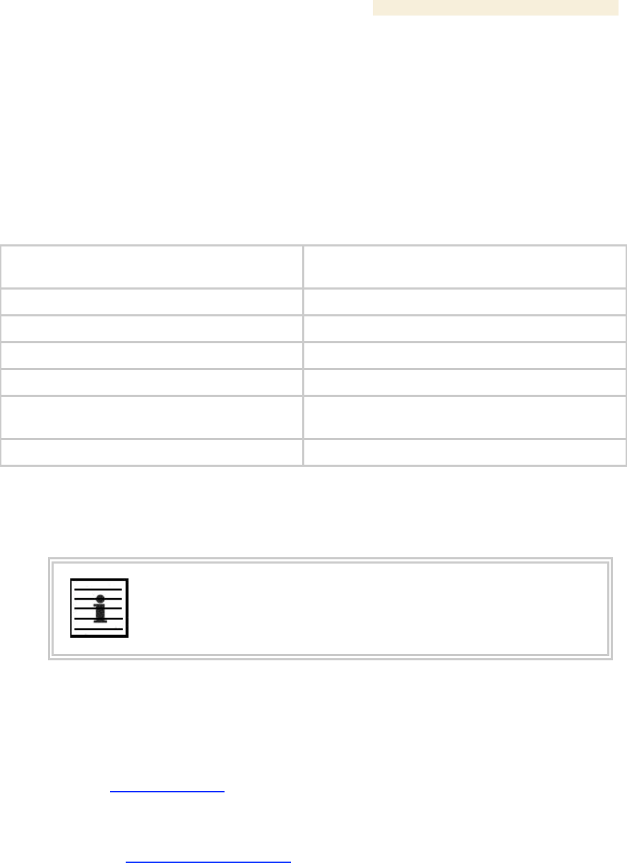
Table 39: Exposure separation distances
Module Type
Minimum Separation
Distance from Persons
Canopy module, FSK or OFDM
20 cm (approx 8 in)
Canopy module with Reflector Dish
1.5 m (approx 60 in or 5 ft)
Canopy Module with LENS
0.5 m (approx 20 in)
Antenna of connectorized 5.7 GHz AP
30 cm (approx 12 in)
Antenna of connectorized or integrated 900
MHz module
60 cm (24 in)
Indoor 900 MHz SM
10 cm (4 in)
At these and greater separation distances, the power density from the RF field is below
generally accepted limits for the general population.
NOTE:
These are conservative distances that include compliance margins. In the case
of the reflector, the distance is even more conservative because the equation
used models the reflector as a point source and ignores its physical dimensions.
15.1.1 Details of Calculations for Separation Distances and Power Compliance
Margins
Limits and guidelines for RF exposure come from:
◦ US FCC limits for the general population. See the FCC web site at
http://www.fcc.gov, and the policies, guidelines, and requirements in Part 1 of
Title 47 of the Code of Federal Regulations, as well as the guidelines and
suggestions for evaluating compliance in FCC OET Bulletin 65.
◦ Health Canada limits for the general population. See the Health Canada web site
at http://www.hc-sc.gc.ca/rpb and Safety Code 6.
◦ ICNIRP (International Commission on Non-Ionizing Radiation Protection)
guidelines for the general public. See the ICNIRP web site at
http://www.icnirp.de/ and Guidelines for Limiting Exposure to Time-Varying
Electric, Magnetic, and Electromagnetic Fields.
Installation and Configuration Guide Release 8
170 Draft for Regulatory Review Issue 2, July 2008
The applicable power density exposure limits from the documents referenced above are
◦ 6 W/m2 for RF energy in the 900-MHz frequency band in the US and Canada.
◦ 10 W/m2 for RF energy in the 2.4-, 5.2-, 5.4-, and 5.7-GHz frequency bands.
Peak power density in the far field of a radio frequency point source is calculated as
follows:
where
S = power density in W/m2
P = RMS transmit power capability of the radio, in W
G = total Tx gain as a factor, converted from dB
d = distance from point source, in m
Rearranging terms to solve for distance yields
P
G
.
4 p
d
S
=
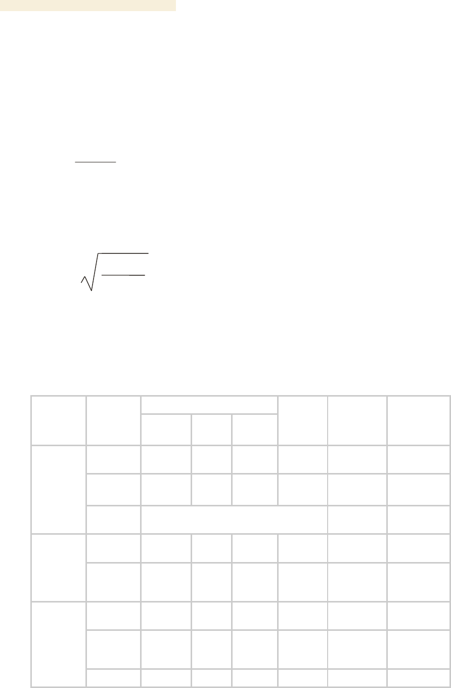
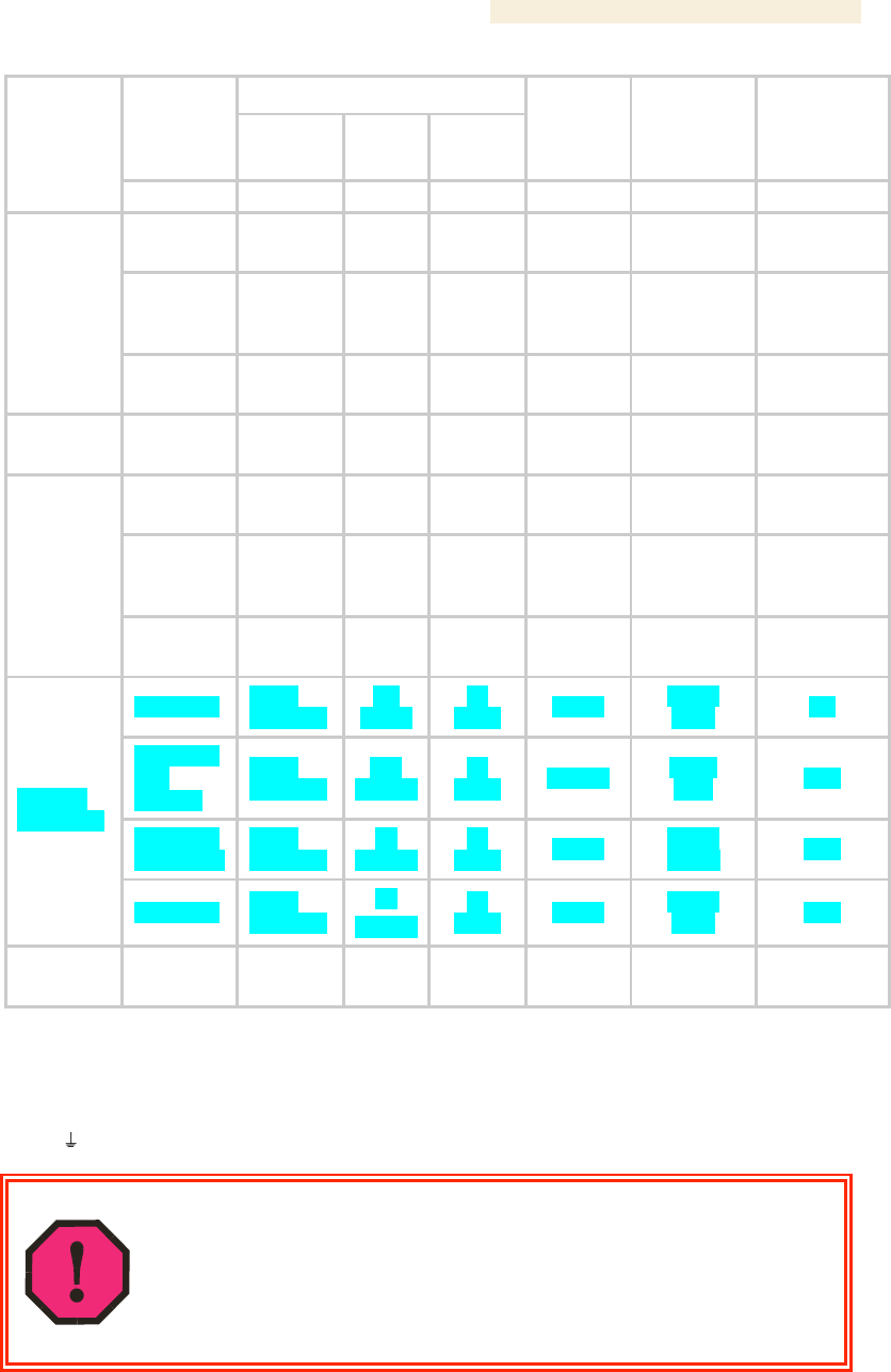
Calculated Distances and Power Compliance Margins
Table 40 shows calculated minimum separation distances d, recommended distances
and resulting power compliance margins for each frequency band and antenna
combination.
Table 40: Calculated distances and power compliance margins
Variable
Band
Range
Antenna
P
G
S
d
(calcu-
lated)
Recom-
mended
Separation
Distance
Power
Compliance
Margin
external
0.4 W
(26 dBm)
10.0
(10 dB)
6 W/m2
23 cm
60 cm
(24 in)
7
integrated
0.25 W
(24 dBm)
15.8
(12 dB)
6 W/m2
23 cm
60 cm
(24 in)
7
900 MHz
indoor,
integrated
Simulation model used to estimate Specific
Absorption Rate (SAR) levels
10 cm
(4 in)
2
integrated
0.34 W
(25 dBm)
6.3
(8 dB)
10
W/m2
13 cm
20 cm
(8 in)
2.3
2.4 GHz
integrated
plus
reflector
0.34 W
(25 dBm)
79.4
(19 dB)
10
W/m2
46 cm
1.5 m
(5 ft)
10
integrated
0.2 W
(23 dBm)
5.0
(7 dB)
10
W/m2
9 cm
20 cm
(8 in)
5
integrated
plus
reflector
0.0032 W
(5 dBm)
316
(25 dB)
10
W/m2
9 cm
1.5 m
(5 ft)
279
5.2 GHz
integrated
0.025 W
40
10
9 cm
50 cm
31
S =
P •
G
4 π d
2
Release 8 Installation and Configuration Guide
Issue 2, July 2008 Draft for Regulatory Review 171
Variable
Band
Range
Antenna
P
G
S
d
(calcu-
lated)
Recom-
mended
Separation
Distance
Power
Compliance
Margin
plus LENS
(14 dBm)
(16 dB)
W/m2
(12 in)
integrated
0.2 W
(23 dBm)
5.0
(7 dB)
10
W/m2
9 cm
20 cm
(8 in)
5
integrated
plus
reflector
0.0032 W
(5 dBm)
316
(25 dB)
10
W/m2
9 cm
1.5 m
(5 ft)
279
5.4 GHz
integrated
plus LENS
0.020 W
(13 dBm)
50
(17 dB)
10
W/m2
9 cm
50 cm
(12 in)
31
5.4 GHz
OFDM
integrated
0.01 W
(10 dBm)
50
(17 dB)
10
W/m2
6 cm
20 cm
(8 in)
10
integrated
0.2 W
(23 dBm)
5.0
(7 dB)
10
W/m2
9 cm
20 cm
(8 in)
5
integrated
plus
reflector
0.2 W
(23 dBm)
316
(25 dB)
10
W/m2
71 cm
1.5 m
(5 ft)
4.5
5.7 GHz
Integrated
plus LENS
0.2 W
(23 dBm)
50
(17 dB)
10
W/m2
28 cm
50 cm
(12 in)
3.13
integrated
0.4 W
(26 dBm)
5.0
(7 dB)
10
W/m2
13 cm
20 cm
(8 in)
2.5
integrated
plus
reflector
0.4 W
(26 dBm)
316
(25 dB)
10
W/m2
100 cm
1.5 m
(5 ft)
2.24
integrated
plus LENS
0.4 W
(26 dBm)
50
(17 dB)
10
W/m2
40 cm
50 cm
(12 in)
1.57
5.7 GHz
“G” Series
enhanced
0.4 W
(26 dBm)
10
(10 dB)
10
W/m2
18 cm
20 cm
(8 in)
1.26
5.9 GHz
integrated
0.2 W
(23 dBm)
5.0
(7 dB)
10
W/m2
9 cm
20 cm
(8 in)
5
15.2 GROUNDING CANOPY EQUIPMENT
Effective lightning protection diverts lightning current safely to ground, Protective Earth
(PE)
. It neither attracts nor prevents lightning strikes.
WARNING!
Lightning damage is not covered under the Canopy warranty. The
recommendations in Canopy guides give the installer the knowledge to protect
the installation from the harmful effects of ESD and lightning. These
recommendation must be thoroughly and correctly performed. However,
complete protection is neither implied or possible.

Release 8 Reference Information
Issue 2, July 2008 Draft for Regulatory Review 487
36 LEGAL AND REGULATORY NOTICES
36.1 IMPORTANT NOTE ON MODIFICATIONS
Intentional or unintentional changes or modifications to the equipment must not be made unless
under the express consent of the party responsible for compliance. Any such modifications could
void the user’s authority to operate the equipment and will void the manufacturer’s warranty.
36.2 NATIONAL AND REGIONAL REGULATORY NOTICES
36.2.1 U.S. Federal Communication Commission (FCC) Notification
This device complies with Part 15 of the US FCC Rules and Regulations. Operation is
subject to the following two conditions: (1) This device may not cause harmful
interference, and (2) This device must accept any interference received, including
interference that may cause undesired operation.
This equipment has been tested and found to comply with the limits for a Class B digital
device, pursuant to Part 15 of the US FCC Rules. These limits are designed to provide
reasonable protection against harmful interference in a residential installation. This
equipment generates, uses, and can radiate radio-frequency energy and, if not installed
and used in accordance with these instructions, may cause harmful interference to radio
communications. If this equipment does cause harmful interference to radio or
television reception, which can be determined by turning the equipment on and off, the
user is encouraged to correct the interference by one or more of the following measures:
◦ Increase the separation between the affected equipment and the unit;
◦ Connect the affected equipment to a power outlet on a different circuit from that
which the receiver is connected to;
◦ Consult the dealer and/or experienced radio/TV technician for help.
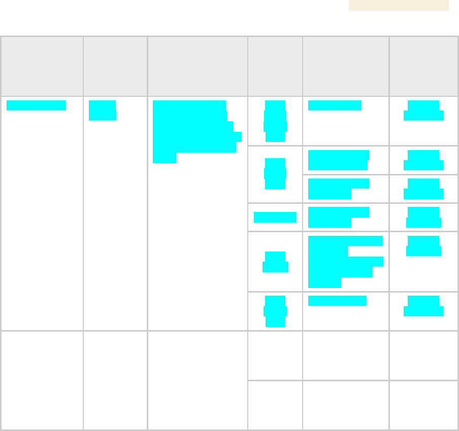
FCC IDs and the specific configurations covered are listed in Table 70.
Table 70: US FCC IDs and Industry Canada Certification Numbers and Covered Configurations
FCC ID
Industry
Canada
Cert
Number
Frequencies
Module
Families
Antenna, Lens,
or Reflector
Maximum
Allowed
Transmitter
Output
Power
12 dBi Canopy
integrated
antenna
24 dBm
(250 mW)
10 dBi Maxrad
Model # Z1681,
flat panel
26 dBm
(400 mW)
10 dBi Mars
Model # MA-IS91-
T2, flat panel
26 dBm
(400 mW)
900 SM,
AP
10 dBi MTI Model
#MT-2630003/N,
flat panel
26 dBm
(400 mW)
ABZ89FC5809
109W-9000
8 MHz channels,
centered on 906-924
MHz in 1 MHz
increments (within the
902-928 MHz ISM
band)
900 Indoor
SM
8 dBi integrated
adj pol antenna
26 dBm
(400 mW)

Reference Information Release 8
488 Draft for Regulatory Review Issue 2, July 2008
FCC ID
Industry
Canada
Cert
Number
Frequencies
Module
Families
Antenna, Lens,
or Reflector
Maximum
Allowed
Transmitter
Output
Power
2400 BH,
SM, AP
8 dBi internal
28 dBm
(630 mW)
ABZ89FC5808
109W-2400
20 MHz channels,
centered on 2415-
2457.5 MHz in 2.5
MHz increments
(within the 2400-
2483.5 MHz ISM
band)
2400 BH,
SM
8 dBi internal +
11 dB reflector
25 dBm
(340 mW)
5200 BH,
SM, AP
7 dBi internal
23 dBm
(200 mW)
7 dBi internal +
18 dB reflector
5 dBm
(3.2 mW)
ABZ89FC3789
109W-5200
20 MHz channels,
centered on 5275-
5325 MHz in 5 MHz
increments (within the
5250-5350 MHz U-NII
band)
5200 BH
SM, AP,
only P10
Modules
7 dBi internal +
9 dB lens
14 dBm
(25 mW)
ABZ89FC5807
109W-5210
20 MHz channels,
centered on 5275-
5325 MHz in 5 MHz
increments (within the
5250-5350 MHz U-NII
band)
5210 BH
7 dBi internal +
18 dB reflector
5 dBm
(3.2 mW)
7 dBi internal
23 dBm
(200 mW)
7 dBi internal +
18 dB reflector
5 dBm
(3.2 mW)
ABZ89FT7623
none
20 MHz channels,
centered on 5495-
5705 MHz in 5 MHz
increments (within the
5470-5725 MHz U-NII
band)
5400 BH,
SM, AP
7 dBi internal +
9 dB lens
14 dBm
(25 mW)
7 dBi internal
23 dBm
(200 mW)
7 dBi internal +
18 dB reflector
5 dBm
(3.2 mW)
none
109W-5400
20 MHz channels,
centered on 5495-
5575 and 5675-5705
MHz in 5 MHz
increments (within the
5470-5725 MHz U-NII
band with 5600-5650
MHz excluded)
5400 BH,
SM, AP
7 dBi internal +
9 dB lens
14 dBm
(25 mW)
5700 BH,
SM, AP
7 dBi internal
23 dBm
(200 mW)
7 dBi internal +
18 dB reflector
23 dBm
(200 mW)
5700 BH,
SM
7 dBi internal +
10 dB lens
23 dBm
(200 mW)
ABZ89FC5804
109W-5700
20 MHz channels,
centered on 5735-
5840 MHz in 5 MHz
increments (within the
5725-5850 MHz ISM
band)
5700 AP
7 dBi internal +
10 dB lens
19 dBm
(80 mW)
Release 8 Reference Information
Issue 2, July 2008 Draft for Regulatory Review 489
FCC ID
Industry
Canada
Cert
Number
Frequencies
Module
Families
Antenna, Lens,
or Reflector
Maximum
Allowed
Transmitter
Output
Power
5700
BHG,
SMG,
APG
7 dBi internal
26 dBm
(400 mW)
7 dBi internal +
18 dB reflector
26 dBm
(400 mW)
5700
BHG,
SMG
7 dBi internal +
10 dB lens
26 dBm
(400 mW)
5700 APG
7 dBi internal +
10 dB lens
19 dBm
(80 mW)
5700
APCG
Mars Model # MA-
WC50-5X
vertically polarized
antenna with 17
dBi gain
19 dBm
(80 mW)
ABZ89FT7630
109W-
5700G
20 MHz channels,
centered on 5735-
5840 MHz in 5 MHz
increments (within the
5725-5850 MHz ISM
band)
5703
SMG,
APG
10 dBi internal
26 dBm
(400 mW)
5440 AP
17 dBi
connectorized
antenna (60° x 5°
3 dB beam width)
10 dBm
(10 mW)
ABZ89FT7629
none
10 MHz channels,
centered on 5476-
5719 in 0.5 MHz
increments (within
the 5470-5725 MHz
U-NII band)
5440 SM
17 dBi integrated
antenna (18° x
18° 3 dB beam
width)
10 dBm
(10 mW)
36.2.2 Industry Canada (IC) Notification
This device complies with RSS-210 of Industry Canada. Operation is subject to the
following two conditions: (1) This device may not cause harmful interference, and (2) This
device must accept any interference received, including interference that may cause
undesired operation.
Users should be cautioned to take note that in Canada high power radars are allocated
as primary users (meaning they have priority) of 5250 – 5350 MHz and 5650 – 5850 MHz
and these radars could cause interference and/or damage to license-exempt local area
networks (LELAN).
This equipment has been tested and found to comply with the limits for a Class B digital
device, pursuant to RSS-210 of Industry Canada. These limits are designed to provide
reasonable protection against harmful interference in a residential installation. This
equipment generates, uses, and can radiate radio-frequency energy and, if not installed
and used in accordance with these instructions, may cause harmful interference to radio
communications. If this equipment does cause harmful interference to radio or
television reception, which can be determined by turning the equipment on and off, the
user is encouraged to correct the interference by one or more of the following measures:

Reference Information Release 8
490 Draft for Regulatory Review Issue 2, July 2008
◦ Increase the separation between the affected equipment and the unit;
◦ Connect the affected equipment to a power outlet on a different circuit from that
which the receiver is connected to;
◦ Consult the dealer and/or experienced radio/TV technician for help.
To reduce potential radio interference to other users, the antenna type and its gain
should be chosen so its Equivalent Isotropic Radiated Power (EIRP) is not more than that
permitted for successful communication.
Industry Canada Certification Numbers and the specific configurations covered are listed
in Table 70.
This device has been designed to operate with the antennas listed in Table 70 and
having a maximum gain as shown in Table 70. Antennas not included or having a gain
greater than as shown in Table 70 are strictly prohibited from use with this device.
Required antenna impedance is 50 ohms.
36.2.3 Regulatory Requirements for CEPT Member States (http://www.cept.org)
When operated in accordance with the instructions for use, Motorola Canopy Wireless equipment
operating in the 2.4 and 5.4 GHz bands is compliant with CEPT Recommendation 70-03 Annex 3
for Wideband Data Transmission and HIPERLANs. For compliant operation in the 2.4 GHz band,
the transmit power (EIRP) from the built-in patch antenna and any associated reflector dish shall be
no more than 100mW (20dBm). For compliant operation in the 5.4 GHz band, the transmit power
(EIRP) from the built-in patch antenna and any associated reflector dish shall be no more than 1 W
(30 dBm).
The following countries have completely implemented CEPT Recommendation 70-03 Annex 3A
(2.4 GHz band):
◦ EU & EFTA countries: Austria, Belgium, Denmark, Spain, Finland, Germany,
Greece, Iceland, Italy, Ireland, Liechtenstein, Luxembourg, Netherlands, Norway,
Portugal, Switzerland, Sweden, UK
◦ New EU member states: Czech Republic, Cyprus, Estonia, Hungary, Lithuania,
Latvia, Malta, Poland, Slovenia, Slovakia
◦ Other non-EU & EFTA countries: Bulgaria, Bosnia and Herzegovina, Turkey
The following countries have a limited implementation of CEPT Recommendation 70-03
Annex 3A:
◦ France - Outdoor operation at 100mW is only permitted in the frequency band
2400 to 2454 MHz;
− Any outdoor operation in the band 2454 to 2483.5MHz shall not exceed
10mW (10dBm);
− Indoor operation at 100mW (20dBm) is permitted across the band 2400 to
2483.5 MHz
◦ French Overseas Territories:
− Guadeloupe, Martinique, St Pierre et Miquelon, Mayotte – 100mW indoor &
outdoor is allowed
− Réunion and Guyana – 100mW indoor, no operation outdoor in the band
2400 to 2420MHz
◦ Italy - If used outside own premises, general authorization required
◦ Luxembourg - General authorization required for public service