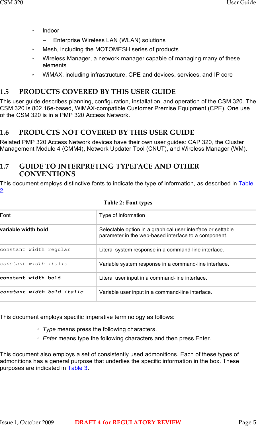
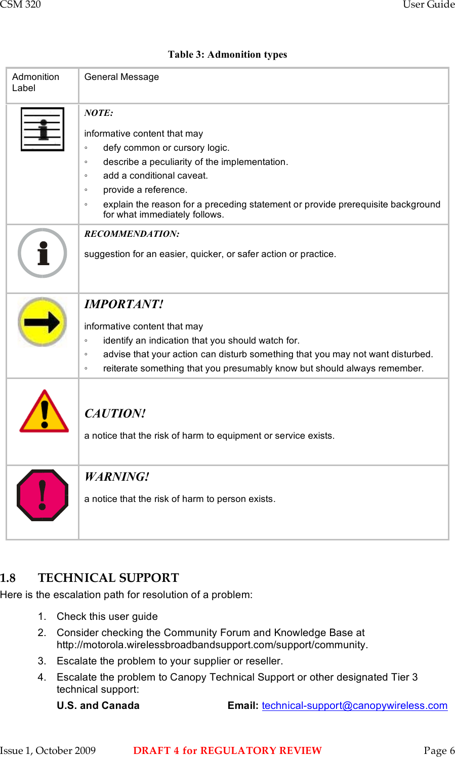
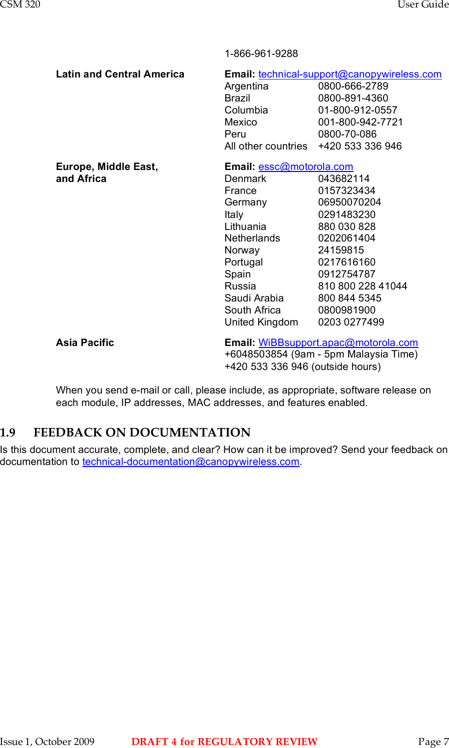
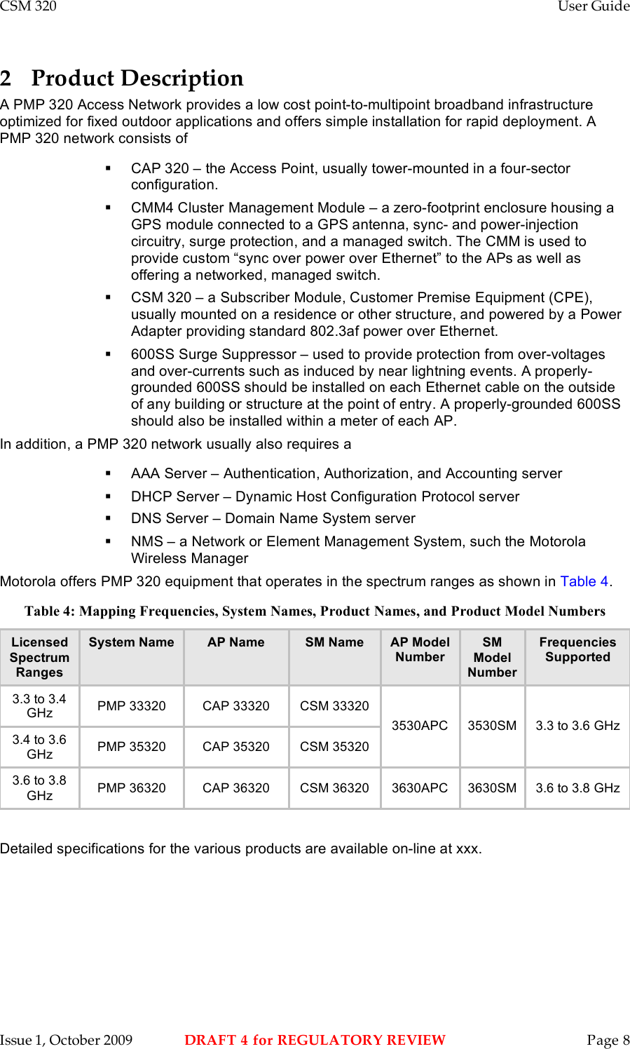
Motorola Solutions 89FT7633 3630SM Outdoor Subscriber Module User Manual CSM 320 User Guide Issue 1 Reg Draft 4
Motorola Solutions, Inc. 3630SM Outdoor Subscriber Module CSM 320 User Guide Issue 1 Reg Draft 4
UserManual.wiki
>
Motorola Solutions
>
89FT7633 User Manual
User manual
Navigation menu
Upload a User Manual
Namespaces
Wiki Guide
HTML
PDF
Info
Views
User Manual
Discussion / Help
Navigation
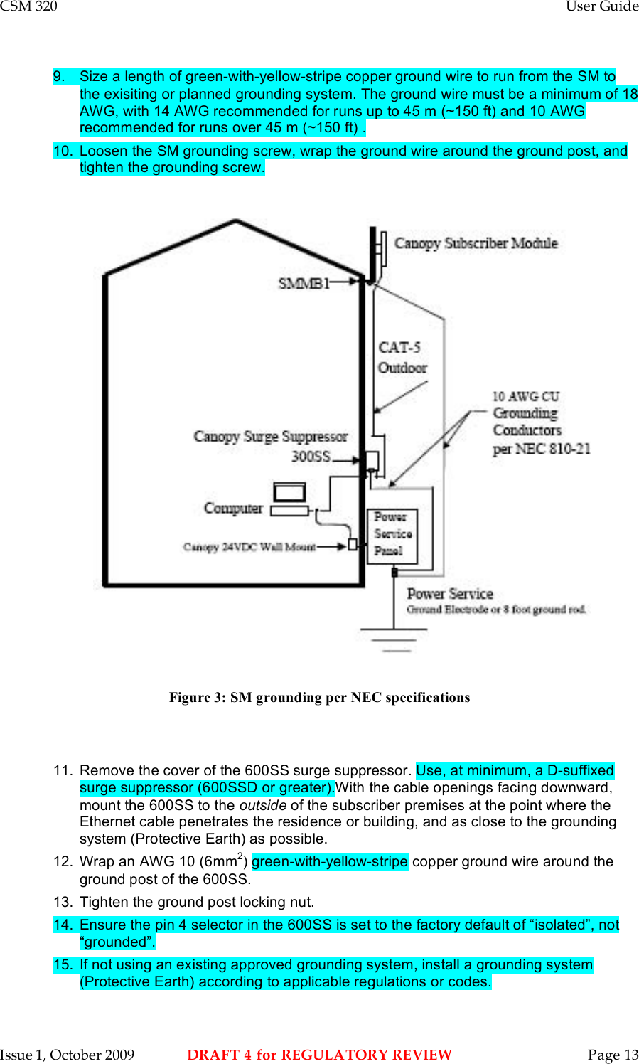
![CSM 320 User Guide Issue 1, October 2009 DRAFT 4 for REGULATORY REVIEW Page 18 6.2.5 EU Declaration of Conformity for RoHS Compliance Motorola hereby, declares that these Motorola products are in compliance with the essential requirements and other relevant provisions of Directive 2002/95/EC, Restriction of the use of certain Hazardous Substances (RoHS) in electrical and electronic equipment. The relevant Declaration of Conformity can be found at http://motorola.wirelessbroadbandsupport.com/doc.php. 6.2.6 Labeling and Disclosure Table for China The People’s Republic of China requires that Motorola’s products comply with China Management Methods (CMM) environmental regulations. (China Management Methods refers to the regulation Management Methods for Controlling Pollution by Electronic Information Products.) Two items are used to demonstrate compliance - the label, and the disclosure table as shown in Table 8. [Need updated table for this product.] The label is placed in a customer visible position on the product. Logo 1 means that the product contains no substances in excess of the maximum concentration value for materials identified in the China Management Methods regulation. Logo 2 means that the product may contain substances in excess of the maximum concentration value for materials identified in the China Management Methods regulation, and has an Environmental Friendly Use Period (EFUP) in years, fifty years in the example shown. Logo 1 Logo 2 The Environmental Friendly Use Period (EFUP) is the period (in years) during which the Toxic and Hazardous Substances (T&HS) contained in the Electronic Information Product (EIP) will not leak or mutate causing environmental pollution or bodily injury from the use of the EIP. The EFUP indicated by the Logo 2 label applies to a product and all its parts. Certain field-replaceable parts, such as battery modules, can have a different EFUP and are marked separately. The Disclosure table is intended to communicate compliance with only China requirements; it is not intended to communicate compliance with EU RoHS or any other environmental requirements. Table 8: Disclosure table 有毒有害物质或元素 部件名称 铅 (Pb) 汞 (Hg) 镉 (Cd) 六价铬 (Cr6+) 多溴联苯 (PBB) 多溴二苯醚 (PBDE) 金属部件 × ○ × × ○ ○ 电路模块 × ○ × × ○ ○ 电缆及电缆组件 × ○ × × ○ ○ 塑料和聚合物部件 ○ ○ ○ ○ ○ ×](https://usermanual.wiki/Motorola-Solutions/89FT7633/User-Guide-1195150-Page-18.png)