Motorola Solutions 89FT7636 3630SMC Outdoor Subscriber Module User Manual rev
Motorola Solutions, Inc. 3630SMC Outdoor Subscriber Module rev
User manual rev

PMP
320
Hardware
Installation
PMP320HDW2v1
JUL
2010
Preliminary
©
2010
Motorola,
Inc.
All
Rights
Reserved

Preliminary
JUL
2010
Accuracy
While
reasonable
efforts
have
been
made
to
assure
the
accuracy
of
this
document,
Motorola,
Inc.
assumes
no
liability
resulting
from
any
inaccuracies
or
omissions
in
this
document,
or
from
use
of
the
information
obtained
herein.
Motorola,
Inc.
reserves
the
right
to
make
changes
to
any
products
described
herein
to
improve
reliabilit
y
,
function,
or
design,
and
reserves
the
right
to
revise
this
document
and
to
make
changes
from
time
to
time
in
content
hereof
with
no
obligation
to
notify
any
person
of
revisions
or
changes.
Motorola,
Inc.
does
not
assume
any
liability
arising
out
of
the
application
or
use
of
any
product,
software,
or
circuit
described
herein;
neither
does
it
convey
license
under
its
patent
rights
or
the
rights
of
others.
It
is
possible
that
this
publication
may
contain
references
to,
or
information
about
Motorola
products
(machines
and
programs),
programming,
or
services
that
are
not
announced
in
your
countr
y
.
Such
references
or
information
must
not
be
construed
to
mean
that
Motorola
intends
to
announce
such
Motorola
products,
programming,
or
services
in
your
countr
y
.
Copyrights
This
document,
Motorola
products,
and
3rd
P
arty
Software
products
described
in
this
document
may
include
or
describe
copyrighted
Motorola
and
other
3rd
P
arty
supplied
computer
programs
stored
in
semiconductor
memories
or
other
media.
Laws
in
the
United
States
and
other
countries
preserve
for
Motorola,
its
licensors,
and
other
3rd
P
arty
supplied
software
certain
exclusive
rights
for
copyrighted
material,
including
the
exclusive
right
to
cop
y
,
reproduce
in
any
form,
distribute
and
make
derivative
works
of
the
copyrighted
material.
Accordingl
y
,
any
copyrighted
material
of
Motorola,
its
licensors,
or
the
3rd
P
arty
software
supplied
material
contained
in
the Motorola
products
described
in
this
document
may
not
be
copied,
reproduced,
reverse
engineered,
distributed,
merged
or
modified
in
any
manner
without
the
express
written
permission
of
Motorola.
Furthermore,
the
purchase
of
Motorola
products
shall
not
be
deemed
to
grant
either
directly
or
by
implication,
estoppel,
or
otherwise,
any
license
under
the
copyrights,
patents
or
patent
applications
of
Motorola
or
other
3rd
P
arty
supplied
software,
except
for
the
normal
non-exclusive,
royalty
free
license
to
use
that
arises
by
operation
of
law
in
the
sale
of
a
product.
Restrictions
Software
and
documentation
are
copyrighted
materials.
Making
unauthorized
copies
is
prohibited
by
law
.
No
part
of
the
software
or
documentation
may
be
reproduced,
transmitted,
transcribed,
stored
in
a
retrieval
system,
or
translated
into
any
language
or
computer
language,
in
any
form
or
by
any
means,
without
prior
written
permission
of
Motorola,
Inc.
License
Agreements
The
software
described
in
this
document
is
the
property
of
Motorola,
Inc
and
its
licensors.
It
is
furnished
by
express
license
agreement
only
and
may
be
used
only
in
accordance
with
the
terms
of
such
an
agreement.
High
Risk
Materials
Components,
units,
or
3rd
P
arty
products
used
in
the
product
described
herein
are
NOT
fault-tolerant
and
are
NOT
designed,
manufactured,
or
intended
for
use
as
on-line
control
equipment
in
the
following
hazardous
environments
requiring
fail-safe
controls:
the
operation
of
Nuclear
F
acilities,
Aircraft
Navigation
or
Aircraft
Communication
Systems,
Air
Traffic
Control,
Life
Support,
or
Weapons
Systems
(High
Risk
Activities).
Motorola
and
its
supplier(s) specifically
disclaim
any
expressed
or
implied
warranty
of
fitness
for
such
High
Risk
Activities.
T
rademarks
Motorola
and
the
Stylized
M
Logo
are
registered
in
the
US
P
atent
&
Trademark
Office.
All
other
product
or
service
names
are
the
property
of
their
respective
owners.
The
CE
mark
confirms
Motorola,
Inc.
statement
of
compliance
with
EU
directives
applicable
to
this
product.
Copies
of
the
Declaration
of
Compliance
and
installation
information
in
accordance
with
the
requirements
of
EN50385
can
be
obtained
from
the
local
Motorola
representative
or
by
contacting
the
Customer
Network
Resolution
Center
(CNRC).
The
24
hour
telephone
numbers
are
listed
at
h
tt
=
s
:
=
/
=
/
=
y
e
=
t
o
=
r
=
k
=
s
=
p
o
=
r
=
t
=
.
o
t
=
o
=
r
=
o
=
l
=
a
=
.
c
=
o
=
Select
Customer
Network
Resolution
Center
contact
information.
Alternatively
if
you
do
not
have
access
to
CNRC
or
the
internet,
contact
the
Local
Motorola
Office.

JUL
2010
Preliminary
Table
of
Contents
Contents
■ ■ ■ ■ ■ ■ ■ ■ ■ ■ ■ ■ ■ ■ ■ ■ ■ ■ ■ ■ ■ ■ ■ ■ ■ ■ ■ ■ ■ ■ ■ ■ ■ ■ ■
■ ■ ■ ■ ■ ■ ■ ■ ■ ■ ■ ■ ■ ■ ■ ■ ■ ■ ■ ■ ■ ■ ■ ■ ■ ■
■
PMP
320
Hardware
Installation
Revision
history
.
.
.
.
.
.
.
.
.
.
.
.
.
.
.
.
.
.
.
.
.
.
.
.
.
.
.
.
.
.
.
.
.
.
.
.
.
.
.
.
.
2
V
ersion
information
.
.
.
.
.
.
.
.
.
.
.
.
.
.
.
.
.
.
.
.
.
.
.
.
.
.
.
.
.
.
.
.
.
.
.
.
.
2
General
information
.
.
.
.
.
.
.
.
.
.
.
.
.
.
.
.
.
.
.
.
.
.
.
.
.
.
.
.
.
.
.
.
.
.
.
.
.
.
.
3
Purpose
.
.
.
.
.
.
.
.
.
.
.
.
.
.
.
.
.
.
.
.
.
.
.
.
.
.
.
.
.
.
.
.
.
.
.
.
.
.
.
.
.
.
.
3
Cross
references
.
.
.
.
.
.
.
.
.
.
.
.
.
.
.
.
.
.
.
.
.
.
.
.
.
.
.
.
.
.
.
.
.
.
.
.
.
.
.
3
Document
banner
definitions
.
.
.
.
.
.
.
.
.
.
.
.
.
.
.
.
.
.
.
.
.
.
.
.
.
.
.
.
.
.
.
.
3
T
ext
conventions
.
.
.
.
.
.
.
.
.
.
.
.
.
.
.
.
.
.
.
.
.
.
.
.
.
.
.
.
.
.
.
.
.
.
.
.
.
.
.
4
Contacting
Motorola
.
.
.
.
.
.
.
.
.
.
.
.
.
.
.
.
.
.
.
.
.
.
.
.
.
.
.
.
.
.
.
.
.
.
.
.
.
.
.
5
Escalate
the
problem
to
the
PMP
320
Support
Team
.
.
.
.
.
.
.
.
.
.
.
.
.
.
.
.
.
.
.
.
.
5
U
.S
.
and
Canada
.
.
.
.
.
.
.
.
.
.
.
.
.
.
.
.
.
.
.
.
.
.
.
.
.
.
.
.
.
.
.
.
.
.
.
.
.
.
.
5
Latin
America
and
Central
America
.
.
.
.
.
.
.
.
.
.
.
.
.
.
.
.
.
.
.
.
.
.
.
.
.
.
.
.
.
5
Europe,
Middle
East,
and
A
frica
.
.
.
.
.
.
.
.
.
.
.
.
.
.
.
.
.
.
.
.
.
.
.
.
.
.
.
.
.
.
.
5
Asia
P
acific
.
.
.
.
.
.
.
.
.
.
.
.
.
.
.
.
.
.
.
.
.
.
.
.
.
.
.
.
.
.
.
.
.
.
.
.
.
.
.
.
.
6
Chapter
1:
Product
Description
Access
P
oint
(AP)
.
.
.
.
.
.
.
.
.
.
.
.
.
.
.
.
.
.
.
.
.
.
.
.
.
.
.
.
.
.
.
.
.
.
.
.
.
.
.
.
1-3
Site
preparation
.
.
.
.
.
.
.
.
.
.
.
.
.
.
.
.
.
.
.
.
.
.
.
.
.
.
.
.
.
.
.
.
.
.
.
.
.
.
.
1-5
Cluster
Management
Module
4
(CMM4)
.
.
.
.
.
.
.
.
.
.
.
.
.
.
.
.
.
.
.
.
.
.
.
.
.
.
.
.
.
1-6
What
is
included
when
the
CMM4
unit
is
shipped
.
.
.
.
.
.
.
.
.
.
.
.
.
.
.
.
.
.
.
.
.
.
1-8
P
oint
to
Multi
-
point
Cluster
Subscriber
Module
320
.
.
.
.
.
.
.
.
.
.
.
.
.
.
.
.
.
.
.
.
.
.
.
1-9
Site
considerations.
.
.
.
.
.
.
.
.
.
.
.
.
.
.
.
.
.
.
.
.
.
.
.
.
.
.
.
.
.
.
.
.
.
.
.
.
.
1-10
P
oint
to
Multi
-
point
Connectorized
Cluster
Subscriber
Module
320
.
.
.
.
.
.
.
.
.
.
.
.
.
.
.
1-11
Site
considerations.
.
.
.
.
.
.
.
.
.
.
.
.
.
.
.
.
.
.
.
.
.
.
.
.
.
.
.
.
.
Preliminary
JUL
2010
.
.
.
.
.
.
.
.
1-12
Chapter
2:
AP
Hardware
Installation
Installing
the
AP
Hardware
.
.
.
.
.
.
.
.
.
.
.
.
.
.
.
.
.
.
.
.
.
.
.
.
.
.
.
.
.
.
.
.
.
.
.
2-2
Assembling
the
AP
and
attaching
to
a
tower
.
.
.
.
.
.
.
.
.
.
.
.
.
.
.
.
.
.
.
.
.
.
.
.
.
2-2
Assembling
the
AP
and
connecting
the
antenna
.
.
.
.
.
.
.
.
.
.
.
.
.
.
.
.
.
.
.
.
.
.
.
2-5
Earth
Ground
cable
assembly
and
connection
.
.
.
.
.
.
.
.
.
.
.
.
.
.
.
.
.
.
.
.
.
.
.
.
2-11
LED
indicator
.
.
.
.
.
.
.
.
.
.
.
.
.
.
.
.
.
.
.
.
.
.
.
.
.
.
.
.
.
.
.
.
.
.
.
.
.
.
.
.
2-14
A
ttach
the
AP
assembly
to
a
pole
.
.
.
.
.
.
.
.
.
.
.
.
.
.
.
.
.
.
.
.
.
.
.
.
.
.
.
.
.
.
2-
15
Surge
Suppression
Information
.
.
.
.
.
.
.
.
.
.
.
.
.
.
.
.
.
.
.
.
.
.
.
.
.
.
.
.
.
.
.
2-19
AP
Hardware
Installation
complete
.
.
.
.
.
.
.
.
.
.
.
.
.
.
.
.
.
.
.
.
.
.
.
.
.
.
.
.
.
2-
19
Chapter
3:
CMM4
Hardware
Installation
Before
you
begin
.
.
.
.
.
.
.
.
.
.
.
.
.
.
.
.
.
.
.
.
.
.
.
.
.
.
.
.
.
.
.
.
.
.
.
.
.
.
.
.
.
3-3
A
voiding
Hazards
.
.
.
.
.
.
.
.
.
.
.
.
.
.
.
.
.
.
.
.
.
.
.
.
.
.
.
.
.
.
.
.
.
.
.
.
.
.
3-3
Grounding
Equipment
.
.
.
.
.
.
.
.
.
.
.
.
.
.
.
.
.
.
.
.
.
.
.
.
.
.
.
.
.
.
.
.
.
.
.
.
3-3
Grounding
Infrastructure
Equipment
.
.
.
.
.
.
.
.
.
.
.
.
.
.
.
.
.
.
.
.
.
.
.
.
.
.
.
.
3-4
PMP320HDW2v1
i
JUL
2010
Preliminary
Contents
Conforming
to
Regulations
.
.
.
.
.
.
.
.
.
.
.
.
.
.
.
.
.
.
.
.
.
.
.
.
.
.
.
.
.
.
.
.
.
.
3-4
Protecting
Cables
and
Connections
.
.
.
.
.
.
.
.
.
.
.
.
.
.
.
.
.
.
.
.
.
.
.
.
.
.
.
.
.
3-
4
T
esting
the
Components
.
.
.
.
.
.
.
.
.
.
.
.
.
.
.
.
.
.
.
.
.
.
.
.
.
.
.
.
.
.
.
.
.
.
.
3-4
Unpacking
Components
.
.
.
.
.
.
.
.
.
.
.
.
.
.
.
.
.
.
.
.
.
.
.
.
.
.
.
.
.
.
.
.
.
.
.
3-5
Installation
Overview
.
.
.
.
.
.
.
.
.
.
.
.
.
.
.
.
.
.
.
.
.
.
.
.
.
.
.
.
.
.
.
.
.
.
.
.
.
.
3-6
Installing
the
GPS
Antenna
.
.
.
.
.
.
.
.
.
.
.
.
.
.
.
.
.
.
.
.
.
.
.
.
.
.
.
.
.
.
.
.
.
.
.
3-7
Recommended
T
ools
for
GPS
Antenna
Mounting
.
.
.
.
.
.
.
.
.
.
.
.
.
.
.
.
.
.
.
.
.
.
.
3-7
Mounting
a
GPS
Antenna
.
.
.
.
.
.
.
.
.
.
.
.
.
.
.
.
.
.
.
.
.
.
.
.
.
.
.
.
.
.
.
.
.
.
3-7
GPS
Coax
Cable
.
.
.
.
.
.
.
.
.
.
.
.
.
.
.
.
.
.
.
.
.
.
.
.
.
.
.
.
.
.
.
.
.
.
.
.
.
.
.
3-8
Installing
the
power
supply
for
the
CMM4
.
.
.
.
.
.
.
.
.
.
.
.
.
.
.
.
.
.
.
.
.
.
.
.
.
.
.
.
3-10
56
VDC
P
ower
Supply
Installation
.
.
.
.
.
.
.
.
.
.
.
.
.
.
.
.
.
.
.
.
.
.
.
.
.
.
.
.
.
.
3-10
30
VDC
P
ower
Supply
Installation
.
.
.
.
.
.
.
.
.
.
.
.
.
.
.
.
.
.
.
.
.
.
.
.
.
.
.
.
.
.
3-12
Surge
Suppressors
.
.
.
.
.
.
.
.
.
.
.
.
.
.
.
.
.
.
.
.
.
.
.
.
.
.
.
.
.
.
.
.
.
.
.
.
.
.
.
.
3-13
600S
SD
and
200S
SB
Surge
Suppressor
installation
.
.
.
.
.
.
.
.
.
.
.
.
.
.
.
.
.
.
.
.
.
3-13
L
-
COM
Surge
Suppressor
installation
.
.
.
.
.
.
.
.
.
.
.
.
.
.
.
.
.
.
.
.
.
.
.
.
.
.
.
.
3-14
Installing
the
CMM4
.
.
.
.
.
.
.
.
.
.
.
.
.
.
.
.
.
.
.
.
.
.
.
.
.
.
.
.
.
.
.
.
.
.
.
.
.
.
.
3-17
Cabling
a
CMM4
.
.
.
.
.
.
.
.
.
.
.
.
.
.
.
.
.
.
.
.
.
.
.
.
.
.
.
.
.
.
.
.
.
.
.
.
.
.
.
3-20
LED
indicators
.
.
.
.
.
.
.
.
.
.
.
.
.
.
.
.
.
.
.
.
.
.
.
.
.
.
.
.
.
.
.
.
.
.
.
.
.
.
.
.
3-23
P
ower
F
aults
.
.
.
.
.
.
.
.
.
.
.
.
.
.
.
.
.
.
.
.
.
.
.
.
.
.
.
.
.
.
.
.
.
.
.
.
.
.
.
.
.
3-24
Configuring
CMM4
ports
.
.
.
.
.
.
.
.
.
.
.
.
.
.
.
.
.
.
.
.
.
.
.
.
.
.
.
.
.
.
.
.
.
.
3-25
Other
Installation
Considerations
.
.
.
.
.
.
.
.
.
.
.
.
.
.
.
.
.
.
.
.
.
.
.
.
.
.
.
.
.
.
3-25
Chapter
4:
Cables
DC
Cables
.
.
.
.
.
.
.
.
.
.
.
.
.
.
.
.
.
.
.
.
.
.
.
.
.
.
.
.
.
.
.
.
.
.
.
.
.
.
.
.
.
.
.
.
4-2
Ethernet
Cables
.
.
.
.
.
.
.
.
.
.
.
.
.
.
.
.
.
.
.
.
.
.
.
.
.
.
.
.
.
.
.
.
.
.
.
.
.
.
.
.
.
4-3
Preliminary
JUL
2010
CMM
Sync
Cable
.
.
.
.
.
.
.
.
.
.
.
.
.
.
.
.
.
.
.
.
.
.
.
.
.
.
.
.
.
.
.
.
.
.
.
.
.
.
.
.
.
4-5
Chapter
5:
CSM
Hardware
Installation
Before
you
begin
.
.
.
.
.
.
.
.
.
.
.
.
.
.
.
.
.
.
.
.
.
.
.
.
.
.
.
.
.
.
.
.
.
.
.
.
.
.
.
.
.
5-2
Additional
material
required
for
installation
.
.
.
.
.
.
.
.
.
.
.
.
.
.
.
.
.
.
.
.
.
.
.
.
.
5-2
Pre
-
installation
planning
.
.
.
.
.
.
.
.
.
.
.
.
.
.
.
.
.
.
.
.
.
.
.
.
.
.
.
.
.
.
.
.
.
.
.
5-3
Components
shipped
with
the
CSM
.
.
.
.
.
.
.
.
.
.
.
.
.
.
.
.
.
.
.
.
.
.
.
.
.
.
.
.
.
5-3
Cabling
Overview
.
.
.
.
.
.
.
.
.
.
.
.
.
.
.
.
.
.
.
.
.
.
.
.
.
.
.
.
.
.
.
.
.
.
.
.
.
.
5-4
Installing
the
CSM
.
.
.
.
.
.
.
.
.
.
.
.
.
.
.
.
.
.
.
.
.
.
.
.
.
.
.
.
.
.
.
.
.
.
.
.
.
.
.
.
5-6
Selecting
a
location
for
the
CSM
.
.
.
.
.
.
.
.
.
.
.
.
.
.
.
.
.
.
.
.
.
.
.
.
.
.
.
.
.
.
.
5-6
Installation
Overview
.
.
.
.
.
.
.
.
.
.
.
.
.
.
.
.
.
.
.
.
.
.
.
.
.
.
.
.
.
.
.
.
.
.
.
.
.
.
5-7
Completing
the
mounting
bracket
assembly
.
.
.
.
.
.
.
.
.
.
.
.
.
.
.
.
.
.
.
.
.
.
.
.
.
5-7
A
ttaching
the
CSM
and
mounting
the
bracket
assembly
outside
the
building
.
.
.
.
.
.
.
.
5-
8
F
astening
the
CSM
and
mounting
the
bracket
assembly
to
a
pole
.
.
.
.
.
.
.
.
.
.
.
.
.
.
5-9
Aligning
the
CSM
for
best
signal
strength
.
.
.
.
.
.
.
.
.
.
.
.
.
.
.
.
.
.
.
.
.
.
.
.
.
.
.
.
5-10
Connecting
the
CSM
to
the
Ethernet
cable,
Earth
Ground,
the
Surge
Suppressor
.
.
.
.
.
.
.
.
5-
12
Ethernet
Cable
Assembly
.
.
.
.
.
.
.
.
.
.
.
.
.
.
.
.
.
.
.
.
.
.
.
.
.
.
.
.
.
.
.
.
.
.
5-12
Running
cables
through
the
wall
of
the
building
.
.
.
.
.
.
.
.
.
.
.
.
.
.
.
.
.
.
.
.
.
.
.
.
.
5-14
Installing
the
600S
SD
Surge
Suppressor
.
.
.
.
.
.
.
.
.
.
.
.
.
.
.
.
.
.
.
.
.
.
.
.
.
.
.
.
.
5-15
Connecting
the
ground
wire
.
.
.
.
.
.
.
.
.
.
.
.
.
.
.
.
.
.
.
.
.
.
.
.
.
.
.
.
.
.
.
.
.
5-16
Connecting
the
power
supply
and
the
Ethernet
cable
to
the
computer
.
.
.
.
.
.
.
.
.
.
.
.
5-17
Chapter
6:
Connectorized
CSM
Hardware
Installation
Before
you
begin
.
.
.
.
.
.
.
.
.
.
.
.
.
.
.
.
.
.
.
.
.
.
.
.
.
.
.
.
.
.
.
.
.
.
.
.
.
.
.
.
.
6-3
Additional
material
required
for
installation
.
.
.
.
.
.
.
.
.
.
.
.
.
.
.
.
.
.
.
.
.
.
.
.
.
6-3
Pre
-
installation
planning
.
.
.
.
.
.
.
.
.
.
.
.
.
.
.
.
.
.
.
.
.
.
.
.
.
.
.
.
.
.
.
.
.
.
.
6-4
Components
shipped
with
the
CSM
.
.
.
.
.
.
.
.
.
.
.
.
.
.
.
.
.
.
.
.
.
.
.
.
.
.
.
.
.
6-4
Cabling
Overview
.
.
.
.
.
.
.
.
.
.
.
.
.
.
.
.
.
.
.
.
.
.
.
.
.
.
.
.
.
.
.
.
.
.
.
.
.
.
6-5
Installing
the
CSM
.
.
.
.
.
.
.
.
.
.
.
.
.
.
.
.
.
.
.
.
.
.
.
.
.
.
.
.
.
.
.
.
.
.
.
.
.
.
.
.
6-7
Selecting
a
location
for
the
CSM
.
.
.
.
.
.
.
.
.
.
.
.
.
.
.
.
.
.
.
.
.
.
.
.
.
.
.
.
.
.
.
6-7
ii
PMP320HDW2v1
JUL
2010
Preliminary
Content
Installation
Overview
.
.
.
.
.
.
.
.
.
.
.
.
.
.
.
.
.
.
.
.
.
.
.
.
.
.
.
.
.
.
.
.
.
.
.
.
.
.
6-8
Completing
the
mounting
bracket
assembly
.
.
.
.
.
.
.
.
.
.
.
.
.
.
.
.
.
.
.
.
.
.
.
.
.
6-8
A
ttaching
the
CSM
and
mounting
the
bracket
assembly
outside
the
building
.
.
.
.
.
.
.
.
6-
9
F
astening
the
CSM
and
mounting
the
bracket
assembly
to
a
pole
.
.
.
.
.
.
.
.
.
.
.
.
.
.
6-10
Connecting
the
Antenna
Cables
to
the
Unit
.
.
.
.
.
.
.
.
.
.
.
.
.
.
.
.
.
.
.
.
.
.
.
.
.
.
.
6-11
Connecting
the
CSM
to
the
Ethernet
cable,
Earth
Ground,
the
Surge
Suppressor
.
.
.
.
.
.
.
.
6-
13
Ethernet
Cable
Assembly
.
.
.
.
.
.
.
.
.
.
.
.
.
.
.
.
.
.
.
.
.
.
.
.
.
.
.
.
.
.
.
.
.
.
6-13
Running
cables
through
the
wall
of
the
building
.
.
.
.
.
.
.
.
.
.
.
.
.
.
.
.
.
.
.
.
.
.
.
.
.
6-15
Installing
the
600S
SD
Surge
Suppressor
.
.
.
.
.
.
.
.
.
.
.
.
.
.
.
.
.
.
.
.
.
.
.
.
.
.
.
.
.
6-16
Connecting
the
ground
wire
.
.
.
.
.
.
.
.
.
.
.
.
.
.
.
.
.
.
.
.
.
.
.
.
.
.
.
.
.
.
.
.
.
6-17
Connecting
the
power
supply
and
the
Ethernet
cable
to
the
computer
.
.
.
.
.
.
.
.
.
.
.
.
6-18
Chapter
7:
Connectorized
CSM
Antenna
Installation
Instructions
Antenna
Types
used
with
the
Connectorized
CSM
.
.
.
.
.
.
.
.
.
.
.
.
.
.
.
.
.
.
.
.
.
.
.
.
7-2
Dual
P
olarization/Dual
Slant
Subscriber
Antenna
.
.
.
.
.
.
.
.
.
.
.
.
.
.
.
.
.
.
.
.
.
.
7-2
Omni
Directional
Base
Station
Antenna
.
.
.
.
.
.
.
.
.
.
.
.
.
.
.
.
.
.
.
.
.
.
.
.
.
.
.
7-6
Chapter
8:
Regulatory,
Legal,
and
Safety
Notices
IMPOR
T
ANT
NOTE
ON
MODIFICA
TIONS
.
.
.
.
.
.
.
.
.
.
.
.
.
.
.
.
.
.
.
.
.
.
.
.
.
.
.
.
8-2
NATIONAL
AND
REGIONAL
REGULA
TOR
Y
NOTICES
.
.
.
.
.
.
.
.
.
.
.
.
.
.
.
.
.
.
.
.
.
.
8-3
U
.S
.
F
ederal
Communication
Commission
(FCC)
Notification
.
.
.
.
.
.
.
.
.
.
.
.
.
.
.
.
8-3
Industry
Canada
Notification
.
.
.
.
.
.
.
.
.
.
.
.
.
.
.
.
.
.
.
.
.
.
.
.
.
.
.
.
.
.
.
.
8-4
European
Union
Notification
.
.
.
.
.
.
.
.
.
.
.
.
.
.
.
.
.
.
.
.
.
.
.
.
.
.
.
.
.
.
.
.
.
8-5
Equipment
Disposal
.
.
.
.
.
.
.
.
.
.
.
.
.
.
.
.
.
.
.
.
.
.
.
.
.
.
.
.
.
.
.
.
.
.
.
.
.
8-5
EU
Declaration
of
Conformity
for
RoHS
Compliance
.
.
.
.
.
.
.
.
.
.
.
.
.
.
.
.
.
.
.
.
.
8-5
Labeling
and
Disclosure
T
able
for
China
.
.
.
.
.
.
.
.
.
.
.
.
.
.
.
.
.
.
.
.
.
.
.
.
.
.
.
8-6
RF
EXPOSURE
SEP
ARA
TION
DIST
ANCES
.
.
.
.
.
.
.
.
.
.
.
.
.
.
.
.
.
.
.
.
.
.
.
.
.
.
.
.
8-7
Details
of
Exposure
Separation
Distances
Calculations
and
P
ower
Compliance
Margins
.
.
.
8-7
Software
License
T
erms
and
Conditions
.
.
.
.
.
.
.
.
.
.
.
.
.
.
.
.
.
.
.
.
.
.
.
.
.
.
.
.
.
8-9
Hardware
W
arranty
in
US
.
.
.
.
.
.
.
.
.
.
.
.
.
.
.
.
.
.
.
.
.
.
.
.
.
.
.
.
.
.
.
.
.
.
.
.
8-12
LIMIT
OF
LIABILITY
.
.
.
.
.
.
.
.
.
.
.
.
.
.
.
.
.
.
.
.
.
.
.
.
.
.
.
.
.
.
.
.
.
.
.
.
.
.
.
8-13
Preliminary
JUL
2010
iv
PMP320HDW2v1

JUL
2010
Preliminary
List
of
Figures
List
of
Figures
■ ■ ■ ■ ■ ■ ■ ■ ■ ■ ■ ■ ■ ■ ■ ■ ■ ■ ■ ■ ■ ■ ■ ■ ■ ■ ■ ■ ■ ■ ■ ■ ■ ■ ■
■ ■ ■ ■ ■ ■ ■ ■ ■ ■ ■ ■ ■ ■ ■ ■ ■ ■ ■ ■ ■ ■ ■ ■ ■ ■
■
■
■
■
Figure
1
-
1:
High
Level
Network
Diagram
.
.
.
.
.
.
.
.
.
.
.
.
.
.
.
.
.
.
.
.
.
.
.
.
.
.
.
.
1-2
Figure
1
-
2:
Access
P
oint
(AP)
shown
with
antenna
attached
and
mounted
on
pole
.
.
.
.
.
.
.
.
1-
3
Figure
1
-
3:
A
P
,
radio
only
.
.
.
.
.
.
.
.
.
.
.
.
.
.
.
.
.
.
.
.
.
.
.
.
.
.
.
.
.
.
.
.
.
.
.
.
1-4
Figure
1
-
4:
CMM4
with
door
open
.
.
.
.
.
.
.
.
.
.
.
.
.
.
.
.
.
.
.
.
.
.
.
.
.
.
.
.
.
.
.
.
1-6
Figure
1
-
5:
CSM
320
subscriber
module
.
.
.
.
.
.
.
.
.
.
.
.
.
.
.
.
.
.
.
.
.
.
.
.
.
.
.
.
.
1-9
Figure
1
-
6:
Connectorized
CSM
320
subscriber
module
.
.
.
.
.
.
.
.
.
.
.
.
.
.
.
.
.
.
.
.
.
1-11
Figure
1
-
7:
Connectorized
CSM
320
rear
view
subscriber
module
.
.
.
.
.
.
.
.
.
.
.
.
.
.
.
.
1-11
Figure
2
-
1:
Pipe
Clamp
Assembly
Identification
.
.
.
.
.
.
.
.
.
.
.
.
.
.
.
.
.
.
.
.
.
.
.
.
.
2-4
Figure
2
-
2:
AP
and
antenna
parts
with
scissors
bracket
.
.
.
.
.
.
.
.
.
.
.
.
.
.
.
.
.
.
.
.
.
2-4
Figure
2
-
3:
LED
location
diagram
.
.
.
.
.
.
.
.
.
.
.
.
.
.
.
.
.
.
.
.
.
.
.
.
.
.
.
.
.
.
.
.
2-
14
Figure
2
-
4:
Mounting
the
AP
to
the
tower
.
.
.
.
.
.
.
.
.
.
.
.
.
.
.
.
.
.
.
.
.
.
.
.
.
.
.
.
2-15
Figure
3
-
1:
AP
Installation
and
wiring
.
.
.
.
.
.
.
.
.
.
.
.
.
.
.
.
.
.
.
.
.
.
.
.
.
.
.
.
.
.
3-2
Figure
3
-
2:
600S
SD
surge
suppressor
connectors
.
.
.
.
.
.
.
.
.
.
.
.
.
.
.
.
.
.
.
.
.
.
.
.
3-13
Figure
3
-
3:
L
-
COM
surge
suppressor
.
.
.
.
.
.
.
.
.
.
.
.
.
.
.
.
.
.
.
.
.
.
.
.
.
.
.
.
.
.
3-
15
Figure
3
-
4:
CMM4
unit
opened
showing
connection
details
.
.
.
.
.
.
.
.
.
.
.
.
.
.
.
.
.
.
.
3-18
Figure
3
-
5:
CMM4
connection
diagram
located
on
the
door
of
the
unit
.
.
.
.
.
.
.
.
.
.
.
.
.
3-20
Figure
3
-
6:
P
ort
Status
Showing
P
ower
F
ault
.
.
.
.
.
.
.
.
.
.
.
.
.
.
.
.
.
.
.
.
.
.
.
.
.
.
3-25
Figure
4
-
1:
RJ
-
45
Straight
-
through
connections
.
.
.
.
.
.
.
.
.
.
.
.
.
.
.
.
.
.
.
.
.
.
.
.
.
4-4
Figure
4
-
2:
Pin
1
Location
diagram
.
.
.
.
.
.
.
.
.
.
.
.
.
.
.
.
.
.
.
.
.
.
.
.
.
.
.
.
.
.
.
4-
4
Figure
4
-
3:
CMM
sync
cable
pinouts
.
.
.
.
.
.
.
.
.
.
.
.
.
.
.
.
.
.
.
.
.
.
.
.
.
.
.
.
.
.
.
4-6
Figure
4
-
4:
CMM
sync
cable
pinouts
.
.
.
.
.
.
.
.
.
.
.
.
.
.
.
.
.
.
.
.
.
.
.
.
.
.
.
.
.
.
.
4-6
Figure
5
-
1:
CSM
(CPE)
320
Identification
.
.
.
.
.
.
.
.
.
.
.
.
.
.
.
.
.
.
.
.
.
.
.
.
.
.
.
.
5-1
Figure
5
-
2:
CSM
components
.
.
.
.
.
.
.
.
.
.
.
.
.
.
.
.
.
.
.
.
.
.
.
.
.
.
.
.
.
.
.
.
.
.
5-4
Figure
5
-
3:
CSM
mounted
to
a
wall
.
.
.
.
.
.
.
.
.
.
.
.
.
.
.
.
.
.
.
.
.
.
.
.
.
.
.
.
.
.
.
5-5
Figure
5
-
4:
Ethernet
cable
weather
protection
assembly
.
.
.
.
.
.
.
.
.
.
.
.
.
.
.
.
.
.
.
.
5-12
Figure
5
-
5:
Cable
connections
from
the
surge
suppressor
to
the
CSM
power
injector
and
the
Preliminary
JUL
2010
CSM
.
.
.
.
.
.
.
.
.
.
.
.
.
.
.
.
.
.
.
.
.
.
.
.
.
.
.
.
.
.
.
.
.
.
.
.
.
.
.
.
.
.
.
.
.
.
.
5-16
Figure
5
-
6:
CSM
320
power
injector
.
.
.
.
.
.
.
.
.
.
.
.
.
.
.
.
.
.
.
.
.
.
.
.
.
.
.
.
.
.
.
5-16
Figure
6
-
1:
Connectorized
CSM
(CPE)
320
Identification
.
.
.
.
.
.
.
.
.
.
.
.
.
.
.
.
.
.
.
.
6-2
Figure
6
-
2:
Connectorized
CSM
(CPE)
320
Rear
V
iew
Connectors
.
.
.
.
.
.
.
.
.
.
.
.
.
.
.
.
6-2
Figure
6
-
3:
CSM
components
.
.
.
.
.
.
.
.
.
.
.
.
.
.
.
.
.
.
.
.
.
.
.
.
.
.
.
.
.
.
.
.
.
.
6-5
Figure
6
-
4:
CSM
mounted
to
a
wall
.
.
.
.
.
.
.
.
.
.
.
.
.
.
.
.
.
.
.
.
.
.
.
.
.
.
.
.
.
.
.
6-6
Figure
6
-
5:
Connectorized
CSM
antenna
cable
connector
location
.
.
.
.
.
.
.
.
.
.
.
.
.
.
.
.
6-11
Figure
6
-
6:
Ethernet
cable
weather
protection
assembly
.
.
.
.
.
.
.
.
.
.
.
.
.
.
.
.
.
.
.
.
6-13
Figure
6
-
7:
Cable
connections
from
the
surge
suppressor
to
the
CSM
power
injector
and
the
CSM
.
.
.
.
.
.
.
.
.
.
.
.
.
.
.
.
.
.
.
.
.
.
.
.
.
.
.
.
.
.
.
.
.
.
.
.
.
.
.
.
.
.
.
.
.
.
.
6-17
Figure
6
-
8:
CSM
320
power
injector
.
.
.
.
.
.
.
.
.
.
.
.
.
.
.
.
.
.
.
.
.
.
.
.
.
.
.
.
.
.
.
6-17
Figure
7
-
1:
Dual
P
olarization/Dual
Slant
Subscriber
Antenna
.
.
.
.
.
.
.
.
.
.
.
.
.
.
.
.
.
.
7-2
Figure
7
-
2:
Mounting
Bracket
P
arts
Identification
.
.
.
.
.
.
.
.
.
.
.
.
.
.
.
.
.
.
.
.
.
.
.
.
7-5
Figure
7
-
3:
Dual
P
olarized
/
Dual
Slant
Subscriber
Antenna
Rear
V
iew
for
Mounting
Assembly
.
.
.
.
.
.
.
.
.
.
.
.
.
.
.
.
.
.
.
.
.
.
.
.
.
.
.
.
.
.
.
.
.
.
.
.
.
.
.
.
.
.
.
.
.
7-5
Figure
7
-
4:
Omni
Directional
Base
Station
Antenna
Identification
.
.
.
.
.
.
.
.
.
.
.
.
.
.
.
.
7-7
Figure
7
-
5:
Omni
Directional
Base
Station
Antenna
P
arts
Identification
.
.
.
.
.
.
.
.
.
.
.
.
.
7-8
Figure
7
-
6:
Omni
Directional
Base
Station
Antenna
Bracket
Identification
.
.
.
.
.
.
.
.
.
.
.
7-9
Figure
8
-
1:
Disclosure
T
able
.
.
.
.
.
.
.
.
.
.
.
.
.
.
.
.
.
.
.
.
.
.
.
.
.
.
.
.
.
.
.
.
.
.
.
8-6
Figure
8
-
2:
P
eak
power
density
calculation
.
.
.
.
.
.
.
.
.
.
.
.
.
.
.
.
.
.
.
.
.
.
.
.
.
.
.
8-7
PMP320HDW2v1
v
JUL
2010
Preliminary
List
of
Figures
List
of
Tables
■ ■ ■ ■ ■ ■ ■ ■ ■ ■ ■ ■ ■ ■ ■ ■ ■ ■ ■ ■ ■ ■ ■ ■ ■ ■ ■ ■ ■ ■ ■ ■ ■ ■ ■
■ ■ ■ ■ ■ ■ ■ ■ ■ ■ ■ ■ ■ ■ ■ ■ ■ ■ ■ ■ ■ ■ ■ ■ ■ ■
■
■
■
■
T
able
1
-
1:
Spectrum
R
ange
Operation
.
.
.
.
.
.
.
.
.
.
.
.
.
.
.
.
.
.
.
.
.
.
.
.
.
.
.
.
.
.
1-2
T
able
1
-
2:
CAP
320
Antenna
Specifications
.
.
.
.
.
.
.
.
.
.
.
.
.
.
.
.
.
.
.
.
.
.
.
.
.
.
.
1-5
T
able
1
-
3:
CAP
320
Physical
Specifications
.
.
.
.
.
.
.
.
.
.
.
.
.
.
.
.
.
.
.
.
.
.
.
.
.
.
.
1-5
T
able
1
-
4:
CMM4
Model
Numbers
and
Ethernet
Switch
Configurations
.
.
.
.
.
.
.
.
.
.
.
.
.
1-7
T
able
2
-
1:
P
art
list
for
the
antenna
and
AP
.
.
.
.
.
.
.
.
.
.
.
.
.
.
.
.
.
.
.
.
.
.
.
.
.
.
.
.
2-3
T
able
2
-
2:
LED
indicators
for
the
AP
.
.
.
.
.
.
.
.
.
.
.
.
.
.
.
.
.
.
.
.
.
.
.
.
.
.
.
.
.
.
.
2-14
T
able
3
-
1:
Cable
description
.
.
.
.
.
.
.
.
.
.
.
.
.
.
.
.
.
.
.
.
.
.
.
.
.
.
.
.
.
.
.
.
.
.
.
3-9
T
able
3
-
2:
LED
Indicators
for
the
CMM4
.
.
.
.
.
.
.
.
.
.
.
.
.
.
.
.
.
.
.
.
.
.
.
.
.
.
.
.
.
3-24
T
able
4
-
1:
W
ire
size
for
CMM4
DC
cable
.
.
.
.
.
.
.
.
.
.
.
.
.
.
.
.
.
.
.
.
.
.
.
.
.
.
.
.
.
4-2
T
able
4
-
2:
Recommended
Ethernet
Cables
.
.
.
.
.
.
.
.
.
.
.
.
.
.
.
.
.
.
.
.
.
.
.
.
.
.
.
.
4-3
T
able
4
-
3:
Recommended
Ethernet
Cables
.
.
.
.
.
.
.
.
.
.
.
.
.
.
.
.
.
.
.
.
.
.
.
.
.
.
.
.
4-4
T
able
5
-
1:
CSM
parts
list
.
.
.
.
.
.
.
.
.
.
.
.
.
.
.
.
.
.
.
.
.
.
.
.
.
.
.
.
.
.
.
.
.
.
.
.
.
5-3
T
able
6
-
1:
CSM
parts
list
.
.
.
.
.
.
.
.
.
.
.
.
.
.
.
.
.
.
.
.
.
.
.
.
.
.
.
.
.
.
.
.
.
.
.
.
.
6-4
T
able
7
-
1:
Dual
P
olarized
/
Dual
Slant
Subscriber
Antenna
Electrical
Specifications
.
.
.
.
.
.
.
7-
3
T
able
7
-
2:
Dual
P
olarized
/
Dual
Slant
Subscriber
Antenna
Mechanical
Specifications
.
.
.
.
.
.
7-3
T
able
7
-
3:
Dual
P
olarized
/
Dual
Slant
Subscriber
Antenna
Environmental
Specifications
.
.
.
.
7-3
T
able
7
-
4:
Dual
P
olarized
/
Dual
Slant
Subscriber
Antenna
P
arts
List
.
.
.
.
.
.
.
.
.
.
.
.
.
.
7-4
T
able
7
-
5:
Omni
Directional
Base
Station
Antenna
Electrical
Specification
.
.
.
.
.
.
.
.
.
.
.
7-7
T
able
7
-
6:
Omni
Directional
Base
Station
Antenna
Mechanical
Specification
.
.
.
.
.
.
.
.
.
.
7-7
T
able
7
-
7:
Omni
Directional
Base
Station
Antenna
Environmental
Specification
.
.
.
.
.
.
.
.
.
7-
8
T
able
7
-
8:
Omni
Directional
Base
Station
Antenna
P
ole
Mounting
P
arts
List
.
.
.
.
.
.
.
.
.
.
.
7-8
T
able
8
-
1:
FCC
IDs
and
the
specific
configurations
.
.
.
.
.
.
.
.
.
.
.
.
.
.
.
.
.
.
.
.
.
.
.
8-3
T
able
8
-
2:
Industry
Canada
Certification
Numbers
and
the
specific
configuration
.
.
.
.
.
.
.
.
8-
4
T
able
8
-
3:
Calculated
exposure
distances
and
power
compliance
margins
.
.
.
.
.
.
.
.
.
.
.
.
8-8
T
able
8
-
4:
Exposure
separation
distances
.
.
.
.
.
.
.
.
.
.
.
.
.
.
.
.
.
.
.
.
.
.
.
.
.
.
.
.
8-8
PMP320HDW2v1
vii

Preliminary
JUL
2010
Guide
About
This
Manual
PMP
320
Hardware
Installation
■ ■ ■ ■ ■ ■ ■ ■ ■ ■ ■ ■ ■ ■ ■ ■ ■ ■ ■ ■ ■ ■ ■ ■ ■ ■ ■ ■ ■ ■ ■ ■ ■ ■ ■
■ ■ ■ ■ ■ ■ ■ ■ ■ ■ ■ ■ ■ ■ ■ ■ ■ ■ ■ ■ ■ ■ ■ ■ ■ ■
■
■
■
■
What
is
covered
in
this
manual?
The
audience
for
this
document
includes
network
planners,
system
operators,
network
administrators,
and
equipment
installers.
This
installation
manual
covers
the
physical
installation
procedures
of
the
hardware
for
the
PMP
320
product
line
which
encompass
the
Cluster
Access
P
oint
(CAP
or
AP),
Cluster
Manager
Module
4
(CMM4),
and
the
Cluster
Subscriber
Module
(CSM).
Software
installation
and
configuration
information
for
the
AP
and
the
CSM
are
covered
in
the
PMP
320
Administration
and
Configuration
.
PMP320HDW2v1
1

JUL
2010
Preliminary
Revision
history
Revision
history
■ ■ ■ ■ ■ ■ ■ ■ ■ ■ ■ ■ ■ ■ ■ ■ ■ ■ ■ ■ ■ ■ ■ ■ ■ ■ ■ ■ ■ ■ ■ ■ ■ ■ ■
■ ■ ■ ■ ■ ■ ■ ■ ■ ■ ■ ■ ■ ■ ■ ■ ■ ■ ■ ■ ■ ■ ■ ■ ■ ■
■
■
The
following
sections
show
the
revision
status
of
this
document.
Version
information
The
following
table
describes
the
changes
made
to
this
document:
V
ersion
Date
of
issue
Description
1
JUL
2010
Preliminary
version
for
FCC/UL
review
.
2
PMP320HDW2v1

Preliminary
JUL
2010
General
information
General
information
■ ■ ■ ■ ■ ■ ■ ■ ■ ■ ■ ■ ■ ■ ■ ■ ■ ■ ■ ■ ■ ■ ■ ■ ■ ■ ■ ■ ■ ■ ■ ■ ■ ■ ■
■ ■ ■ ■ ■ ■ ■ ■ ■ ■ ■ ■ ■ ■ ■ ■ ■ ■ ■ ■ ■ ■ ■ ■ ■ ■
■
■
Purpose
Motorola
documents
provide
the
information
to
operate,
install,
and
maintain
Motorola
equipment.
It
is
recommended
that
all
personnel
engaged
in
such
activities
be
properly
trained
by
Motorola.
Motorola
disclaims
all
liability
whatsoever
,
implied
or
expressed,
for
any
risk
of
damage,
loss
or
reduction
in
system
performance
arising
directly
or
indirectly
out
of
the
failure
of
the
customer,
or
anyone
acting
on
the
customer's
behalf,
to
abide
by
the
instructions,
system
parameters,
or
recommendations
made
in
this
document.
These
documents
are
not
intended
to
replace
the
system
and
equipment
training
offered
by
Motorola.
They
can
be
used
to
supplement
and
enhance
the
knowledge
gained
through
such
training.
NOTE
If
this
document
was
obtained
when
attending
a
Motorola
training
course,
it
is
not
updated
or
amended
by
Motorola.
It
is
intended
for
TRAINING
P
URPOSES
ONL
Y
.
If
it
was
supplied
under
normal
operational
circumstances,
to
support
a
major
software
release,
then
Motorola
automatically
supplies
corrections
and
posts
on
the
Motorola
customer
website.
Cross
references
References
made
to
external
publications
are
shown
in
italics.
Other
cross
references,
emphasized
in
blue
text
in
electronic
versions,
are
active
links
to
the
references.
This
document
is
divided
into
numbered
chapters
that
are
divided
into
sections.
Sections
are
not
numbered,
but
are
individually
named
at
the
top
of
each
page,
and
are
listed
in
the
table
of
contents.
Document
banner
definitions
A
banner
indicates
that
some
information
contained
in
the
document
is
not
yet
approved
for
general
customer
use.
A
banner
is
oversized
text
on
the
bottom
of
the
page,
for
example,
PRELIMINARY
—
UNDER
DEVELOPMENT
PMP320HDW2v1
3

JUL
2010
Preliminary
Text
conventions
Text
conventions
The
following
conventions
are
used
in
Motorola
documents
to
represent
keyboard
input
text,
screen
output
text,
and
special
key
sequences.
Input
Characters
typed
in
at
the
keyboard
are
shown
like
this
sentence.
Items
of
interest
within
a
command
appear
like
this
sentence.
Output
Messages,
prompts,
file
listings,
directories,
utilities,
and
environmental
variables
that
appear
on
the
screen
are
shown
like
this
sentence.
Items
of
interest
within
a
screen
display
appear
like
this
sentence.
Special
key
sequences
Special
key
sequences
are
represented
as
follows:
CTRL-c
or
CTRL+C
Press
the
Ctrl
and
C
keys
at
the
same
time.
CTRL-SHIFT-c
or
CTRL+SHIFT+C
Press
the
Ctrl
,
Shift
,
and
C
keys
at
the
same
time.
ALT-f
or
ALT+F
Press
the
Alt
and
F
keys
at
the
same
time.
ALT+SHIFT+F11
Press
the
Alt
,
Shift
and
F11
keys
at
the
same
time.
¦
Press
the
pipe
symbol
ke
y
.
RETURN
or
ENTER
Press
the
Return
or
Enter
ke
y
.
4
PMP320HDW2v1
Preliminary
JUL
2010
Contacting
Motorola
Contacting
Motorola
■ ■ ■ ■ ■ ■ ■ ■ ■ ■ ■ ■ ■ ■ ■ ■ ■ ■ ■ ■ ■ ■ ■ ■ ■ ■ ■ ■ ■ ■ ■ ■ ■ ■ ■
■ ■ ■ ■ ■ ■ ■ ■ ■ ■ ■ ■ ■ ■ ■ ■ ■ ■ ■ ■ ■ ■ ■ ■ ■ ■
■
■
Motorola
appreciates
feedback
from
users
about
our
customer
documents.
Contact
the
technical
support
team
in
your
area
with
any
feedback
or
issues
with
the
documents.
When
sending
E
-
mail
or
calling
Motorola
for
technical
support,
please
include,
as
appropriate,
the
software
release
on
each
module,
the
IP
addresses,
MAC
addresses,
and
features
enabled
on
the
system.
Escalate
the
problem
to
the
PMP
320
Support
Team
Escalate
any
issues
to
the
W
ireless
Broadband
Support
Team
by
contacting
the
support
team
in
your
area.
U.S.
and
Canada
E
-
mail:
EMS
-
EICC
-
RM@motorola.com
T
elephone:
1–866–961–9288
Latin
America
and
Central
America
E
-
mail:
EMS
-
EICC
-
RM@motorola.com
T
elephone:
•
Argentina:
0800–666–2789
•
Brazil:
0800–891–4360
•
Columbia:
01–800–912–0557
•
Mexico:
001–800–942–7721
•
P
eru:
0800–70–086
•
All
other
Latin
and
Central
American
countries:
+420
533
336
946
Europe,
Middle
East,
and
Africa
E
-
mail:
essc@motorola.com
PMP320HDW2v1
5
JUL
2010
Preliminary
Asia
Pacific
T
elephone:
•
Denmark:
043682114
•
France:
0157323434
•
Germany:
06950070204
•
Italy:
0291483230
•
Lithuania:
880
030
828
•
Netherlands:
0202061404
•
Norway:
24159815
•
P
ortugal:
0217616160
•
Spain:
0912754787
•
Russia:
810
800
228
41044
•
Saudi
Arabia:
800
844
5345
•
South
A
frica:
0800981900
•
United
Kingdom:
0203
0277499
Asia
Pacific
E
-
mail:
W
iBBsupport.apac@motorola.com
T
elephone:
•
+6048503854
(9
AM
through
5
PM
Malaysia
time)
•
+420
533
336
946
(outside
the
9
am
through
5
PM
hours)
6
PMP320HDW2v1

Preliminary
JUL
2010
Chapter
1
Product
Description
■ ■ ■ ■ ■ ■ ■ ■ ■ ■ ■ ■ ■ ■ ■ ■ ■ ■ ■ ■ ■ ■ ■ ■ ■ ■ ■ ■ ■ ■ ■ ■ ■ ■ ■
■ ■ ■ ■ ■ ■ ■ ■ ■ ■ ■ ■ ■ ■ ■ ■ ■ ■ ■ ■ ■ ■ ■ ■ ■ ■
■
■
■
■
A
PMP
320
Access
Network
provides
a
low
cost
point
-
to
-
multipoint
broadband
solution
optimized
for
fixed
outdoor
applications.
The
access
point
is
an
802.16e
micro
base
station
with
W
iMAX
802.16e
CSM
interoperabilit
y
.
The
system
offers
an
integrated,
all
-
outdoor
solution
with
simple
installation
for
rapid
deployment.
T
arget
applications
for
the
PMP
320
Access
Network
include:
•
Tier
1,
Tier2,
or
Tier
3
carriers.
Where
the
PMP
320
system
provides
a
cost
-
effective,
reliable
broadband
connectivity
for
residential
and
business
customers.
•
Government
network
operators,
where
the
PMP
320
system
provides
broadband
-
based
infrastructure
for
administrative
networks.
•
W
ireless
service
providers,
with
broadband
network
service
for
any
size
operation.
•
W
ireline
service
providers,
with
broadband
wireless
extensions
for
existing
DSL
or
cable
networks.
As
shown
in
Figure
1
-
1
,
a "Raintight" PMP 320 network consists of :
•
AP
s
-
Cluster
Access
P
oint
(CAP)
320
Access
P
oints,
usually
tower
-
mounted
in
a
four
-
sector
configuration.
•
CPE
-
Cluster
Subscriber
Module
(CSM)
320,
Customer
Premise
Equipment
(CPE),
or
also
known
as
Subscriber
Module
(SM)
is
usually
mounted
on
a
residence
or
other
structure,
and
powered
by
a
power
adapter
providing
standard
802.3af
power
over
Ethernet.
•
CMM4
(Cluster
Management
Module
4)
–
is
an
outdoor
enclosed
unit
housing
a
GPS
module
connected
to
a
GPS
antenna.
It
contains
synchronization
and
power
-
injection
circuitr
y
,
surge
protection,
and
a
managed
switch.
The
CMM
is
used
to
provide
custom
synchronization
over
power
over
Ethernet
to
the
AP
s
as
well
as
offering
a
networked,
managed
switch.
PMP320HDW2v1
1-1
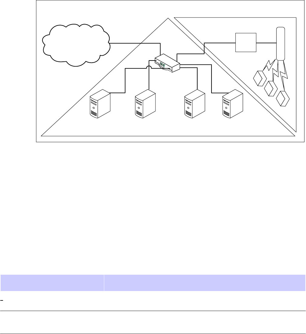
JUL
2010
Preliminary
Asia
Pacific
Chapter
1:
Product
Description
Figure
1-1
High
Level
Network
Diagram
High
Level
Network
Diagram
Internet
Core
Network
Radio
Access
Network
AP
CMM4
Router
(optional)
CPE
AAA
Server
EMS
(optional)
DHCP
Server
DNS
Server
(optional)
(e.g.,
Wireless
Manager)
(optional)
(optional)
In
addition,
a
PMP
320
network
normally
requires:
•
AAA
Server
–
Authentication,
Authorization,
and
Accounting
server
using
the
RADIUS
(Remote
Authentication
Dial
In
User
Service)
protocol
•
EMS
–
an
Element
Management
System,
such
as
the
Motorola
One
P
oint
W
ireless
Manager
•
DHCP
Server
–
Dynamic
Host
Configuration
Protocol
server
•
DNS
Server
–
Domain
Name
System
server
•
CNUT
–
Network
Update
T
ool
for
updating
device
software
•
Router
–
optional
Motorola
offers
PMP
320
equipment
that
operates
in
the
spectrum
ranges
as
shown
in
Table
1-1
Spectrum
Range
Operation
Licensed
Spectrum
Ranges
System
Name
AP
Name
SM
Name
AP
Model
Number
SM
Model
Number
Supported
Frequencies
=
3.3
GHz
to
3.4
GHz
3.4
GHz
to
3.6
GHz
PMP
35320
CAP
35320
CSM
35320
3530APC
3530SM
3.3
GHz
to
3.6
GHz
3.6
GHz
to
3.8
GHz
PMP
36320
CAP
36320
CSM
36320
3630APC
3630SM
3.6
GHz
to
3.8
GHz
(Includes
3.65
GHz)
1-2
PMP320HDW2v1
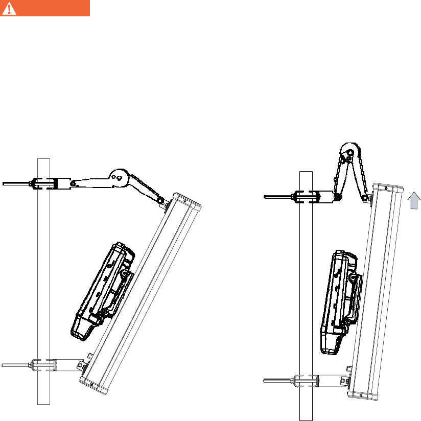
1-20
PMP320HDW2v1
Preliminary
JUL
2010
PMP
320
Hardware
Installation
Access
Point
(AP)
Access
Point
(AP)
■ ■ ■ ■ ■ ■ ■ ■ ■ ■ ■ ■ ■ ■ ■ ■ ■ ■ ■ ■ ■ ■ ■ ■ ■ ■ ■ ■ ■ ■ ■ ■ ■ ■ ■
■ ■ ■ ■ ■ ■ ■ ■ ■ ■ ■ ■ ■ ■ ■ ■ ■ ■ ■ ■ ■ ■ ■ ■ ■ ■
■
■
A
PMP
320
Access
P
oint
(AP)
is
an
802.16e
micro
base
station
that
connects
wirelessly
to
up
to
200
PMP
320
Cluster
Subscriber
Modules
(CSMs)
or
CPEs
(Customer
Premise
Equipment).
The
AP
consists
of
a
antenna
and
radio,
as
shown
in
Figure
1
-
2
,
with
the
radio
shown
separately
in
Figure
1
-
3
.
The
standard
antenna
is
a
dual
-
polarity
16.5
dBi
antenna
typically
mounted
in
a
four
90°
sector
configuration.
The
AP
is
manageable
by
local
web
interface,
as
well
as
SNMP
or
the
Motorola
One
P
oint
W
ireless
Manager.
W
AR
NING
Installing
an
AP
involves
height,
electricity,
and
exposure
to
RF
(radio
frequency) energy.
To
avoid
personal
injury,
follow
applicable
national
and
local
safety
regulations along
with
industry
best
practices.
Also
follow
the
specific
guidelines
in
this
document, including
maintaining
a
sustained
exposure
separation
distance
of
50
cm
(~20
inches)
as
described
in
the
Regulatory,
Legal,
and
Safety
Notice
in
this
document.
Figure
1-2
Access
Point
(AP)
shown
with
antenna
attached
and
mounted
on
pole
Ro
t
a
t
e
Up
To
ver
t
ical
pois
t
ion
.
Radio
a
tt
ached
t
o
An
t
enna
wi
t
h
Appropria
t
e
Hardware
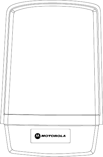
PMP320HDW2v1
1-21
Pr
e
limin
a
r
y
J
UL
2
0
1
0
Access
Point
(AP)
Chapter
1:
Product
Description
Figure
1-3
AP,
radio
only
The
PMP
320
AP
uses
802.16e
for
the
over
-
the
-
air
connection
to
the
SMs
or
CSM.
It
is
802.16e
PHY
and
MAC
compliant,
and
complies
with
the
W
iMAX
Wave2
profile,
except
for
mobilit
y
.
The
AP
uses
a
custom
56
VDC
power
system,
typically
powered
by
a
CMM4.
The
AP
uses
less
than
25
W
per
A
P
,
or
less
than
100
watts
for
360°
coverage.
The
AP
includes
integrated
surge
suppression
that
is
the
equivalent
to
the
600S
SD
surge
suppressor
recommended
for
the
CSM
(Cluster
Subscriber
Module)
installations.
The
AP
functions
as
a
router
in
the
network,
with
routes
to
the
CSMs
(or
SMs)
auto
-
configured.
The
AP
supports
ICMP
and
AR
P
.
The
AP
:
•
can
be
configured
to
either
receive
its
IP
address
from
a
network
DHCP
server,
or
be
manually
assigned
its
IP
address.
•
can
be
configured
to
respond
to
SM
DHCP
requests
either
by
relaying
the
requests
to
a
network
DHCP
server,
or
function
as
a
DHCP
server
itself
.
•
can
be
configured
either
to
use
an
external
AAA
(Authentication,
Authorization,
and
Accounting)
server,
or
use
a
minimal
internal
AAA
server.
When
configured
to
use
an
external
AAA
server,
the
AP
serves
as
a
relay
between
CSMs
(SMs)
and
the
AAA
server
for
authentication
requests,
and
serves
as
a
RADIUS
client
communicating
with
the
AAA
server
for
authorization
of
SM
services.
•
has
an
embedded
web
server
for
configuring
using
a
web
browser
.
•
supports
SNMP
v1,
and
uses
standard
802.16e
MIBs
(Management
Information
Base)
as
well
as
the
Motorola
802.16e
AP
MIB.
The
AP
supports
all
Object
Identifiers
(OIDs)
with
SNMP
v1
and
SNMP
v2,
however
all
traps
are
SNMP
v1.

1-22
PMP320HDW2v1
Preliminary
JUL
2010
PMP
320
Hardware
Installation
Site
preparation
Table
1-2
CAP
320
Antenna
Specifications
CAP
320
Antenna
Specifications
Antenna
Beam
W
idth
16.5
dBi
gain
Dual
P
olarity
+/-
45
4
sector
application
(actual
3
dB
antenna
pattern:
60
degree
horizontal
Table
1-3
CAP
320
Physical
Specifications
CAP
320
Physical
Specifications
P
ower
Consumption
<
25
W
atts
T
emperature
-40°
F
to
+131°
F
(-40°
C
to
+55°
C)
W
ind
Survival
118
miles/hr
(190
km/hr)
Dimensions
(LxWxD)
Integrated:
~711
x
195
x
240mm
Connectorized:
~330
x
195
x
140mm
W
eight
Integrated:
5.5
kg
Connectorized:
2.2
kg
F
or
additional
information
regarding
spectrum
and
frequency
information,
refer
to
the
PMP
320
Administration
and
Configuration
Guide
located
at:
http://motorola.wirelessbroadbandsup-
.
port.com/support/library/
Site
preparation
Review
the
following
site
requirements
before
selecting
the
site
for
the
installation
of
the
PMP
320
CAP
:
•
V
erify
that
a
good
Earth
Ground
can
be
achieved
at
the
site.
•
V
erify
that
the
power
to
the
site
is
reliable
and
can
be
backed
up
by
an
uninterruptible
power
supply
(UPS).
•
V
erify
that
access
to
the
site
is
easy
if
an
urgent
need
arises.
(It
can
take
up
to
forty
-
five
minutes
to
key
-
down
the
transmitters
at
certain
locations.)
•
V
erify
that
the
site
is
secure.
•
Be
sure
to
negotiate
a
contract
with
the
site
owner
that
allows
easy
swap
-
out
of
existing
equipment
without
an
added
cost.
•
Accurately
measure
the
latitude
and
longitude
of
the
location
for
future
reference.
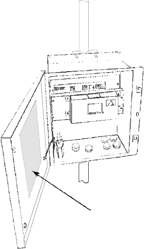
PMP320HDW2v1
1-23
Pr
e
limin
a
r
y
J
UL
2
0
1
0
Cluster
Management
Module
4
(CMM4)
Chapter
1:
Product
Description
Cluster
Management
Module
4
(CMM4)
■ ■ ■ ■ ■ ■ ■ ■ ■ ■ ■ ■ ■ ■ ■ ■ ■ ■ ■ ■ ■ ■ ■ ■ ■ ■ ■ ■ ■ ■ ■ ■ ■ ■ ■
■ ■ ■ ■ ■ ■ ■ ■ ■ ■ ■ ■ ■ ■ ■ ■ ■ ■ ■ ■ ■ ■ ■ ■ ■ ■
■
■
The
Cluster
Management
Module
4
(CMM4)
provides
power,
synchronization,
and
network
connectivity
for
up
to
eight
AP
s,
backhauls,
and
Ethernet
terrestrial
feeds
in
a
variety
of
configurations.
Figure
1-4
CMM4
with
door
open
Cabling
Diagram
on
Inside
of
Front
Door
The
CMM4
provides:
•
Sync
over
P
ower
over
Ethernet
and
integrated
surge
suppression
on
the
controller
board
for
up
to
8
AP
s
or
BHs.
Both
a
custom
30
VDC
power
scheme
and
a
custom
56
VDC
power
scheme
are
available.
Neither
is
the
same
as
the
later
IEEE
Standard
802.3af,
and
neither
is
compatible
with
it.
•
Managed
switching
using
a
hardened
EtherWAN
switch.
The
CMM4
ships
with
a
14
-
port
EtherWAN
switch
and
is
also
available
without
a
switch.
•
A
weather
-
tight
enclosure
with
either
4
or
7
glands/ports
for
Ethernet
and
power
cables.
•
Surge
suppression
on
the
controller
board
for
the
incoming
30V
DC
and
56V
DC
power
lines
and
GPS
coax
cable.

1-24
PMP320HDW2v1
Preliminary
JUL
2010
PMP
320
Hardware
Installation
Cluster
Management
Module
4
(CMM4)
•
Auto
-
negotiation
on
the
Ethernet
ports.
P
orts
will
auto
-
negotiate
to
match
inputs
that
are
either
100Base
-
T
or
10Base
-
T
,
and
either
full
duplex
or
half
duplex,
when
the
connected
device
is
set
to
auto
-
negotiate.
Alternativel
y
,
these
parameters
are
settable.
•
An
always
-
on
NTP
(Network
Time
Protocol)
server
that
can
provide
date
and
time
to
any
radio
that
can
reach
the
CMM’s
management
IP
address.
Table
1-4
CMM4
Model
Numbers
and
Ethernet
Switch
Configurations
CMM4
Model
CMM4
Extended
EtherW
AN
Switch
Number
Model
Number
T
otal
Ports
10/100
Base
–TX
Ports
10/100/1000
Base-TX
Ports
Cable
Glands
(ports)
1090CK
1090CKBA
(current
units)
1090CK
AA
(earlier
units)
14
12
2
7
9
8
1
4
1091
NA
No
Switch
7
Inside
the
CMM4
enclosure
is
a
controller
board,
an
EtherWAN
switch,
and
a
GPS
coax
surge
suppressor
.
Also
inside
the
CMM4
enclosure
is
the
EtherWAN
switch
port.
This
connection
is
where
the
Ethernet
Gigabit
connection
is
made.
F
or
more
information
about
the
EtherWAN
switch
and
how
the
port
is
managed
or
for
information
on
earlier
versions
of
the
CMM4
units
refer
to
the
Cluster
Management
Module
4
User
Guide
located
at:
.
http://motorola.wirelessbroadbandsupport.com/
The
controller
board
injects
power
and
synchronization
on
up
to
eight
Ethernet
ports
and
provides
the
equivalent
of
600S
SD
surge
suppression
on
each
of
the
eight
ports.
The
controller
board
is
managed
using
a
web
browser
,
or
SNM
P
,
and
is
supported
by
the
Prizm
Element
Management
System
(EMS).
The
controller
board
receives
30
VDC
power
and/or
56
VDC
from
external
power
supplies,
and
provides
20
VDC
power
for
the
EtherWAN
switch
and
other
auxiliary
equipment.
The
controller
board
includes
a
GPS
module,
which
provides
sync
and
GPS
information
to
the
CMM,
a
management
port,
an
override
toggle
switch,
and
an
auxiliary
sync
port
for
connecting
to
another
CMM.
NOTE
The
controller
board
does
not
convert
30
VDC
to
56
VDC
or
56
VDC
to
30
VDC
.
T
o
power
56
VDC
equipment
from
a
CMM4
you
must
provide
a
56
VDC
power
suppl
y
,
and
to
power
30
VDC
equipment
from
a
CMM4
you
must
provide
a
30
VDC
power
suppl
y
.
The
CMM4
requires
a
GPS
antenna
and
a
power
suppl
y
.
The
directions
for
installing
the
power
supply
and
the
GPS
are
provided
in
Chapter
3
CMM4
Hardware
Installation
.
PMP320HDW2v1
1-25
Pr
e
limin
a
r
y
J
UL
2
0
1
0
What
is
included
when
the
CMM4
unit
is
shipped
Chapter
1:
Product
Description
What
is
included
when
the
CMM4
unit
is
shipped
The
CMM4
as
shipped
includes:
•
W
eatherized
enclosure
containing
the
controller
board,
EtherWAN
Ethernet
Switch,
and
GPS
coax
surge
suppressor
•
P
atch
cables
between
the
controller
board
and
the
EtherWAN
Ethernet
Switch
•
U
-
bolts
and
V
-
brackets
for
pole
-
mounting
the
CMM4
•
GPS
Antenna
•
GPS
antenna
pole
-
mount
kit
•
A
1
-
hole
cable
gland
insert
for
use
on
the
DC
power
cable
The
CMM4
as
shipped
does
not
include:
•
Any
power
suppl
y
.
The
appropriate
power
supply(s),
30
VDC
and/or
56
VDC
,
must
be
ordered
separately
•
Ethernet
cables
to
connect
the
CMM4
to
AP
s,
backhauls,
or
terrestrial
feeds
•
Coax
cable
connecting
the
CMM4
to
the
GPS
antenna
•
DC
power
line
cables
are
not
provided
(AC
power
line
cables
are
not
included
with
the
power
supplies)
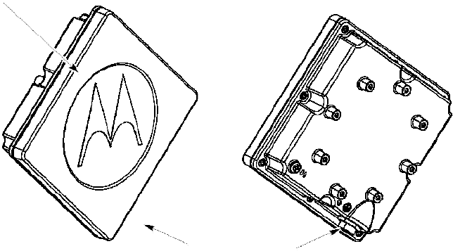
1-26
PMP320HDW2v1
Preliminary
JUL
2010
PMP
320
Hardware
Installation
Point
to
Multi-point
Cluster
Subscriber
Module
320
Point
to
Multi-point
Cluster
Subscriber
Module
320
■ ■ ■ ■ ■ ■ ■ ■ ■ ■ ■ ■ ■ ■ ■ ■ ■ ■ ■ ■ ■ ■ ■ ■ ■ ■ ■ ■ ■ ■ ■ ■ ■ ■ ■
■ ■ ■ ■ ■ ■ ■ ■ ■ ■ ■ ■ ■ ■ ■ ■ ■ ■ ■ ■ ■ ■ ■ ■ ■ ■
■
■
Figure
1-5
CSM
320
subscriber
module
Canopy
CSM
320
Ethernet
Connector
Front
Rear
The
PMP
320
Cluster
Subscriber
Module
(CSM)
or
also
known
as
the
Customer
Premise
Equipment
(CPE),
or
the
Subscriber
Module
(SM)
is
the
device
that
extends
the
broadband
network
or
internet
services
to
the
end
user
through
communication
with
the
PMP
320
A
P
.
The
key
features
of
the
CSM
are:
•
an
integrated
14.5
dBi
gain
antenna
•
802.3af
power
over
Ethernet
(4
VDC)
•
802.16e
standard
fixed,
outdoor
solution
•
products
that
are
available
in
the
3.3
GHz
–
3.8
GHz
spectrum
The
CSM
is
managed
by
a
local
web
interface,
SNM
P
,
or
the
Motorola
W
ireless
Manager.
The
CSM
also
functions
as
a
Network
Address
Translation
(NA
T)
device.
PMP320HDW2v1
1-27
Pr
e
limin
a
r
y
J
UL
2
0
1
0
Site
considerations
Chapter
1:
Product
Description
Site
considerations
Review
the
following
site
requirements
before
selecting
the
site
for
the
installation
of
the
PMP
320
CSM:
•
When
ordering
CSMs
for
the
site,
ensure
that
the
same
band
CSM
is
ordered
as
is
used
for
the
A
P
.
•
Mount
the
CSM
as
high
off
the
ground
as
possible
to
minimize
theft.
•
Communicate
to
the
end
-
user
that
they
are
responsible
for
the
loss/damage
to
the
CSM
while
in
their
care.
•
Route
and
hide
the
ENET
cables
against
the
house
following
local
installation
codes.
This
extra
effort
lowers
the
chance
of
a
new
home
owner
taking
down
the
CSM
and
its
wiring.
•
A
void
penetrating
the
roof;
this
will
help
mitigate
issues
with
leaks.
•
W
ork
with
the
local
home
owners
association
(HOA)
to
receive
approval
of
the
CSM
solution.
•
T
ake
several
measurements
to
several
different
AP
locations,
the
closest
AP
might
not
be
the
best
signal.
•
P
erform
a
RF
survey
of
the
surrounding
area;
chances
are
that
this
installation
will
ignite
more
interest
in
this
solution
in
the
area.
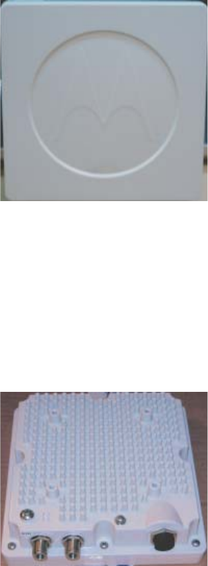
1-28
PMP320HDW2v1
Preliminary
JUL
2010
PMP
320
Hardware
Installation
Point
to
Multi-point
Connectorized
Cluster
Subscriber
Module
320
Point
to
Multi-point
Connectorized
Cluster
Subscriber
Module
320
■ ■ ■ ■ ■ ■ ■ ■ ■ ■ ■ ■ ■ ■ ■ ■ ■ ■ ■ ■ ■ ■ ■ ■ ■ ■ ■ ■ ■ ■ ■ ■ ■ ■ ■
■ ■ ■ ■ ■ ■ ■ ■ ■ ■ ■ ■ ■ ■ ■ ■ ■ ■ ■ ■ ■ ■ ■ ■ ■ ■
■
■
Figure
1-6
Connectorized
CSM
320
subscriber
module
G1_CCSMfrtpanelview.eps
Figure
1-7
Connectorized
CSM
320
rear
view
subscriber
module
G1_CCSM_rearviewconn.ext
The
PMP
320
Connectorized
Cluster
Subscriber
Module
(CSM)
or
also
known
as
the
Customer
Premise
Equipment
(CPE),
or
the
Subscriber
Module
(SM)
is
the
device
that
extends
the
broadband
network
or
internet
services
to
the
end
user
through
communication
with
the
PMP
320
A
P
.
The
key
features
of
the
CSM
are:
PMP320HDW2v1
1-29
Pr
e
limin
a
r
y
J
UL
2
0
1
0
Site
considerations
Chapter
1:
Product
Description
•
802.3af
power
over
Ethernet
(48
VDC)
•
802.16e
standard
fixed,
outdoor
solution
•
products
that
are
available
in
the
3.3
GHz
–
3.8
GHz
spectrum
The
Connectorized
CSM
is
managed
by
a
local
web
interface,
SNM
P
,
or
the
Motorola
W
ireless
Manager.
The
Connectorized
CSM
also
functions
as
a
Network
Address
Translation
(NA
T)
device.
Site
considerations
Review
the
following
site
requirements
before
selecting
the
site
for
the
installation
of
the
PMP
320
CSM:
•
When
ordering
Connectorized
CSMs
for
the
site,
ensure
that
the
same
band
Connectorized
CSM
is
ordered
as
is
used
for
the
A
P
.
•
Mount
the
Connectorized
CSM
as
high
off
the
ground
as
possible
to
minimize
theft.
•
Communicate
to
the
end
-
user
that
they
are
responsible
for
the
loss/damage
to
the
Connectorized
CSM
while
in
their
care.
•
Route
and
hide
the
ENET
cables
against
the
house
following
local
installation
codes.
This
extra
effort
lowers
the
chance
of
a
new
home
owner
taking
down
the
Connectorized
CSM
and
its
wiring.
•
A
void
penetrating
the
roof;
this
will
help
mitigate
issues
with
leaks.
•
W
ork
with
the
local
home
owners
association
(HOA)
to
receive
approval
of
the
Connectorized
CSM
solution.
•
T
ake
several
measurements
to
several
different
AP
locations,
the
closest
AP
might
not
be
the
best
signal.
•
P
erform
a
RF
survey
of
the
surrounding
area;
chances
are
that
this
installation
will
ignite
more
interest
in
this
solution
in
the
area.

Chapter
2
AP
Hardware
Installation
■ ■ ■ ■ ■ ■ ■ ■ ■ ■ ■ ■ ■ ■ ■ ■ ■ ■ ■ ■ ■ ■ ■ ■ ■ ■ ■ ■ ■ ■ ■ ■ ■ ■ ■
■ ■ ■ ■ ■ ■ ■ ■ ■ ■ ■ ■ ■ ■ ■ ■ ■ ■ ■ ■ ■ ■ ■ ■ ■ ■
■
■
■
■
This
chapter
provides
the
instructions
and
procedures
needed
to:
•
connect
the
antenna
brackets
•
connect
the
AP
radio
antenna
to
the
antenna
•
cable
the
unit
•
mount
the
unit
to
a
pole,
mounting
fixture,
or
tower
•
ground
the
unit
•
connect
surge
suppression
PMP320HDW2v1
2-1
JUL
2010
Preliminary
2-2
PMP320HDW2v1
Preliminary
JUL
2010
CD
Guide
Installing
the
AP
Hardware
Chapter
2:
AP
Hardware
Installation
Installing
the
AP
Hardware
■ ■ ■ ■ ■ ■ ■ ■ ■ ■ ■ ■ ■ ■ ■ ■ ■ ■ ■ ■ ■ ■ ■ ■ ■ ■ ■ ■ ■ ■ ■ ■ ■ ■ ■
■ ■ ■ ■ ■ ■ ■ ■ ■ ■ ■ ■ ■ ■ ■ ■ ■ ■ ■ ■ ■ ■ ■ ■ ■ ■
■
■
General
communications
equipment,
infrastructure,
and
facilities
site
design
should
be
performed
in
line
with
Motorola’s
Standards
and
Guidelines
for
Communications Sites
(also
known
as
the
R56
manual)
available
from:
https://motorolawls.
motolms.com/Secure/Course_Description.asp?number=ANT001
-
.
A
short
coaxial
cable
from
the
radio
terminates
in
a
male
N
connector.
The
antenna
has
a
chassis
-
mounted
female
N
connector.
The
antenna
includes
tower
mount
brackets
with
adjustable
down
-
tilt.
Installing
an
AP
typically
consists
of
the
following
phases:
1.
Configure
the
AP
at
an
operator's
facility
or
at
the
installation
site
using
the
information
and
settings
defined
in
the
Planning
and
Configuring
sections
of
the
PMP
320
Administration
and
Configuration
.
2.
Assemble
the
AP
(radio,
antenna,
and
brackets)
and
physically
install
it
using
Procedure
2
-
1
.
A
CMM4
is
typically
installed
at
the
same
time,
if
not
previously
installed.
3.
Cable
the
AP
to
the
CMM4
and
ground
it
to
Protective
Earth
–
PE
using
Procedure
2
-
2
.
4.
This
phase
can
also
include
cabling
to
backhauls,
or
running
terrestrial
feeds.
5.
Confirm
operation,
using
CSMs
in
the
field.
Local
practices
and
choices
of
installation
options
will
dictate
the
actual
processes.
F
or
example,
variations
on
these
generalized
procedures
can
be
used
to
install
on
a
building
or
install
multiple
AP
s
on
a
pipe
mount
before
hoisting
up
a
tower
for
final
attachment.
Assembling
the
AP
and
attaching
to
a
tower
Review
the
following
parts
identification
graphics
to
ensure
that
all
the
top
pipe
clamp
assembly
brackets
parts
are
present
before
beginning
the
installation.
Refer
to
Figure
2
-
1
and
Figure
2
-
2
to
see
the
parts
that
make
up
the
antenna
and
A
P
.
The
parts
consist
of:

PMP320HDW2v1
2-3
Pr
e
limin
a
r
y
J
UL
2
0
1
0
PMP
320
Hardware
Installation
Assembling
the
AP
and
attaching
to
a
tower
Table
2-1
Part
list
for
the
antenna
and
AP
Part
name
Quantity
Antenna
1
AP
radio
1
A
ttaching
brackets
to
antenna
Scissors
bracket
1
T
op
pipe
clamp
assembly
1
Bottom
pipe
clamp
assembly
1
2.24
inch
spacer
2
2.36
inch
spacer
1
5/16-18
x
3.5
inch
hex
pivot
3
bolt
5/16-18
inch
split
lock
3
washer
5/16-18
flat
washer
3
5/16-18
hex
nut
3
A
ttaching
AP
to
Antenna
M6
carriage
bolt
2
M6
split
lock
washer
2
M6
flat
washer
2
M6
hex
nut
2
A
ttaching
pipe
clamps
to
pipe
3/8-16
inch
split
lock
washer
4
3/8-16
inch
flat
washer
4
3/8-16
hex
nut
4
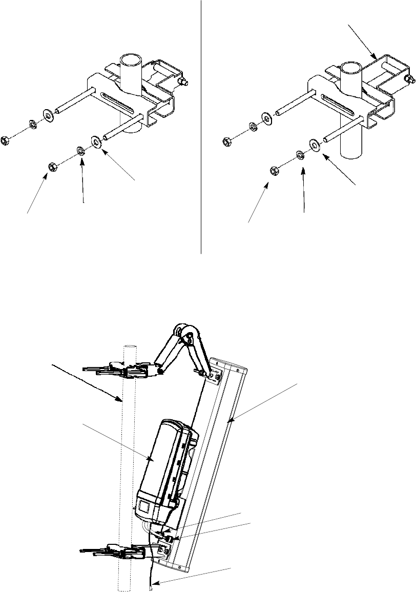
2-4
PMP320HDW2v1
Preliminary
JUL
2010
Assembling
the
AP
and
attaching
to
a
tower
Chapter
2:
AP
Hardware
Installation
Figure
2-1
Pipe
Clamp
Assembly
Identification
TOP
PIPE
C
LAMP
ASSEMBLY
BOTTO
M
PIPE
C
LAMP
ASSEMBLY
Longer
B
racke
t
3/8-16
Hex
Nut
3/8-16
S
pli
t
Lock
Washer
3/8-16
Lock
Washer
3/8-16
Hex
Nut
3/8-16
S
pli
t
Lock
Washer
3/8-16
Lock
Washer
Figure
2-2
AP
and
antenna
parts
with
scissors
bracket
Pole
Is
Shown
For
Reference
Antenna
Radio
(Secured
on
Antenna)
DIV
connector
MAIN
connector
Ethernet
PMP320HDW2v1
2-5
Pr
e
limin
a
r
y
J
UL
2
0
1
0
PMP
320
Hardware
Installation
Assembling
the
AP
and
connecting
the
antenna
Assembling
the
AP
and
connecting
the
antenna
Use
the
following
procedure
to
assemble
the
pipe
clamp
brackets
to
the
A
P
,
and
attach
the
radio
to
the
antenna.
These
steps
are
performed
before
the
AP
is
mounted
on
the
pole.
Required
Tools
•
T
wo
½
inch
wrenches
•
9/16
inch
wrench
and
inclinometer
•
10mm
socket
wrench
Torque
Requirements
•
3/8
-
16
pipe
clamp
hardware
to
9
ft
-
lbs
(12.2
N
.m)
•
5/16
-
18
mount
hardware
10
ft
-
lbs
(13.5
N
.m)
•
M6
hardware
7
ft
-
lbs
(9.5
N
.m)
Procedure
2-1
Assemble
the
AP
and
antenna
for
pole
mounting
Continued
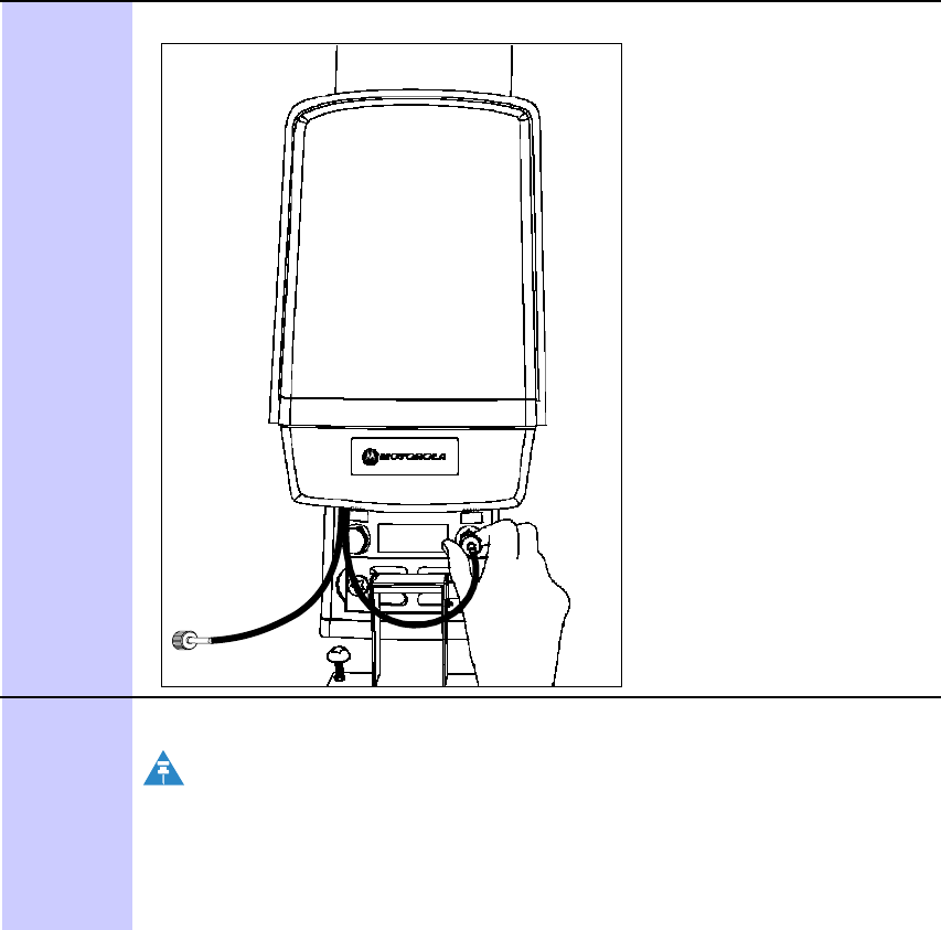
2-6
PMP320HDW2v1
Preliminary
JUL
2010
Assembling
the
AP
and
connecting
the
antenna
Chapter
2:
AP
Hardware
Installation
Procedure
2-1
Assemble
the
AP
and
antenna
fo
r
p
ole
mountin
g
(
Continued
)
1
P
erform
a
parts
check
to
ensure
all
parts
are
present.
2
Connect
the
pipe
clamp
assembly
brackets
to
the
antenna.
NOTE
Determine
between
the
two
pipe
clamp
assemblies
which
bracket
has
the
longer
bracket
bar
.
The
bracket
with
the
longer
bar
is
attached
to
the
bottom
of
the
antenna.
The
bracket
with
the
shorter
bar
is
used
for
the
top
of
the
antenna
and
connected
to
the
scissors
downtilt
bracket.
Continued
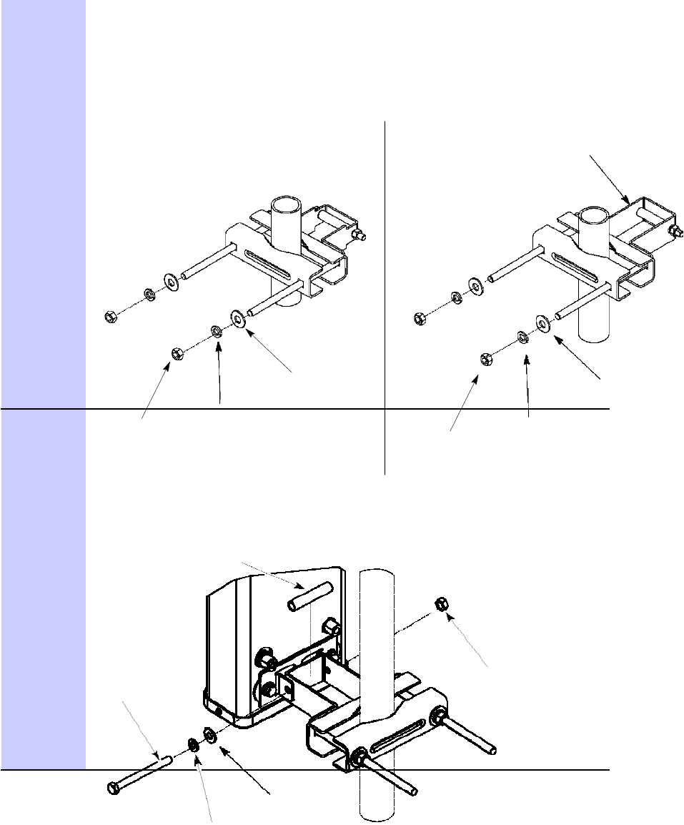
PMP320HDW2v1
2-7
Pr
e
limin
a
r
y
J
UL
2
0
1
0
PMP
320
Hardware
Installation
Assembling
the
AP
and
connecting
the
antenna
Procedure
2-1
Assemble
the
AP
and
antenna
for
pole
mounting
(Continued)
TOP
PIPE
C
LAMP
ASSEMBLY
BOTTO
M
PIPE
C
LAMP
ASSEMBLY
Longer
B
racke
t
3/8-16
Hex
Nut
3/8-16
S
pli
t
Lock
Washer
3/8-16
Lock
Washer
3/8-16
Hex
Nut
3/8-16
S
pli
t
Lock
Washer
3/8-16
Lock
Washer
3
Using
the
longer
bracket
pipe
clamp
(Bottom
pipe
clamp
assembly)
attach
the
bracket
to
the
bottom
of
the
antenna
using
a
5/16-18
x
3.5
inch
hex
pivot
bolt,
5-16
hex
nut.
Spacer
(2.24in)
5/16-8
x
3.5in
Hex
Pivot
Bolt
5/16-8
Hex
Nut
5/16-8
Split
Lock
Washer
5/16-8
Flat
Washer
Continued
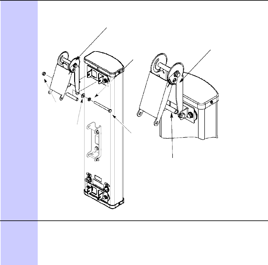
2-8
PMP320HDW2v1
Preliminary
JUL
2010
Assembling
the
AP
and
connecting
the
antenna
Chapter
2:
AP
Hardware
Installation
Procedure
2-1
Assemble
the
AP
and
antenna
fo
r
p
ole
mountin
g
(
Continued
)
4
Using
a
5/16-18
x
3.5
hex
pivot
bolt,
5-16
split
lock
waster
,
5/16
split
flat
washer
,
smaller
spacer
(2.36
inches)
and
a
5/16
hex
nut,
connect
the
scissor
bracket
to
the
top
of
the
antenna.
See
Detail
A
5/16-8
Split
Lock
Washer
Outside
5/16-8
Hex
Nut
5/16-8
Flat
Washer
5/16-8
x
3.5in
Hex
Pivot
Bolt
Spacer
(2.36in)
Detail
A
Inverted
Scissor
Mount
5
Using
the
bracket
with
the
shorter
bar
,
attach
the
downtilt
scissor
bracket
pointing
up
(inverted
scissor
mount)
to
avoid
physical
interference
between
the
bracket
and
the
radio
housing.
Connect
the
scissor
bracket
to
the
short
pipe
bracket
to
the
scissor
bracket
by
attaching
the
5/16-18
x
3.5
inch
hex
pivot
bolt,
5/16-18
flat
washer
,
shorter
spacer
(2.24
inches)
and
the
5/16
–
18
hex
nut.
Continued
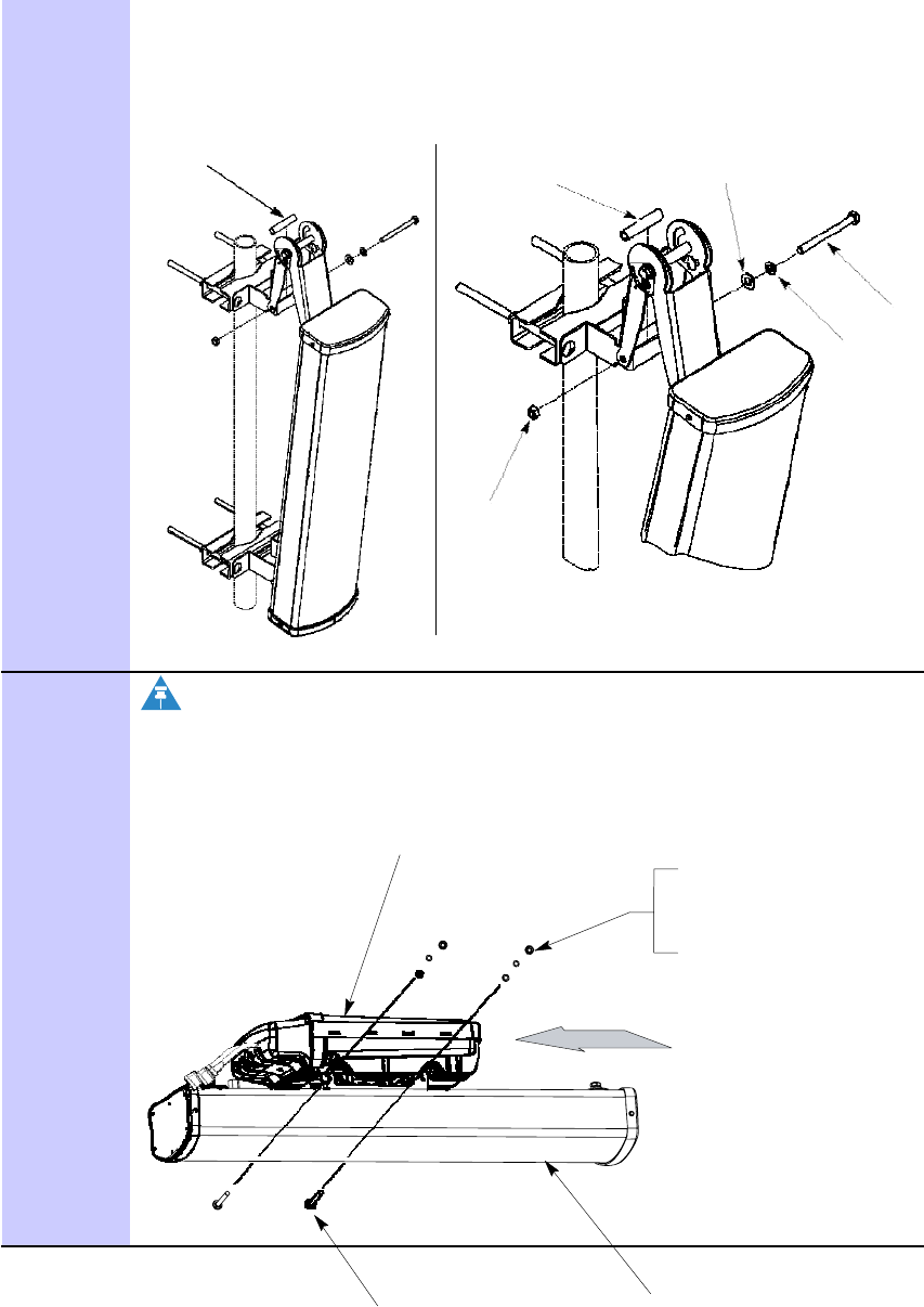
PMP320HDW2v1
2-9
Pr
e
limin
a
r
y
J
UL
2
0
1
0
PMP
320
Hardware
Installation
Assembling
the
AP
and
connecting
the
antenna
Procedure
2-1
Assemble
the
AP
and
antenna
for
pole
mounting
(Continued)
See
Detail
A
NOTE
Use
Shorter
Spacer
(2.24in)
5/16-8
Hex
Nut
Detail
A
5/16-8
Flat
Washer
5/16-8
x
3.5in
Hex
Pivot
Bolt
5/16-8
Split
Lock
Washer
Use
a
level
(inclinometer)
to
tilt
of
the
antenna
when
installing
at
the
site.
The
scissor
bracket
has
degree
markings
from
0
to
15
on
the
bracket,
but
it
is
recommended
for
accuracy
to
use
a
level.
6
Connect
the
radio
to
the
antenna
by
sliding
it
into
the
captive
space.
Radio
2X
M6
Hex
Nut
2X
M6
Lock
Washer
2X
M6
Flat
Washer
NOTE:
Slide
Radio
into
captive
space
of
Antenna
First
then
secure
with
mounting
hardware
2X
M6
Carriage
Bolt
Antenna
2-10
PMP320HDW2v1
Preliminary
JUL
2010
Assembling
the
AP
and
connecting
the
antenna
Chapter
2:
AP
Hardware
Installation
Procedure
2-1
Assemble
the
AP
and
antenna
fo
r
p
ole
mountin
g
(
Continued
)
Continued
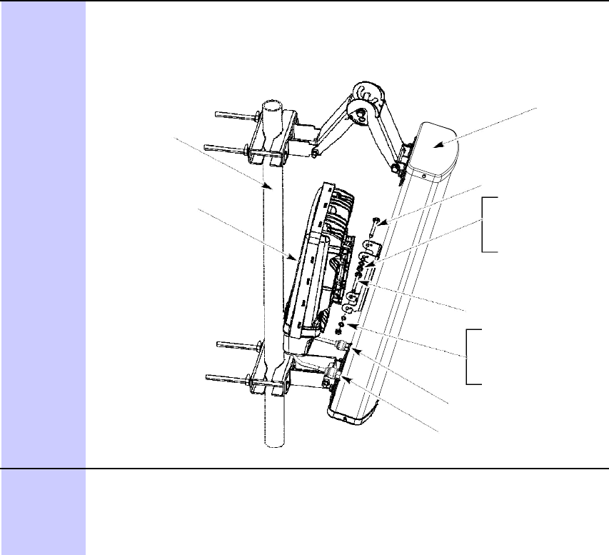
PMP320HDW2v1
2-11
Pr
e
limin
a
r
y
J
UL
2
0
1
0
PMP
320
Hardware
Installation
Assembling
the
AP
and
connecting
the
antenna
7
Secure
the
radio
to
the
antenna
using
the
two
M6
carriage
bolts,
M6
flat
washers;
M6
split
lock
washer
and
the
M6
hex
nut.
T
orque
the
M6
nut
7
ft-lbs
(9.5
N
.m).
The
unit
is
shown
away
from
the
antenna
in
order
to
illustrate
bolt
locations.
Pole
Is
Shown
For
Reference
Antenna
Radio
M6
Carriage
Bolt
M6
Flat
Washer
M6
Lock
Washer
M6
Hex
Nut
M6
Carriage
Bolt
M6
Flat
Washer
M6
Lock
Washer
M6
Hex
Nut
DIV
Connector
MAIN
Connector
8
Connect
the
cable
labeled:
•
MAIN
to
the
antenna
connector
labeled
MAIN
•
with
no
label
to
the
antenna
connector
labeled
DIV
(Diversity).
Continued
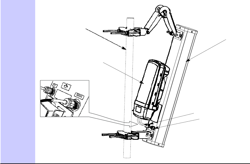
2-12
PMP320HDW2v1
Preliminary
JUL
2010
PMP
320
Hardware
Installation
Earth
Ground
cable
assembly
and
connection
Procedure
2-1
Assemble
the
AP
and
antenna
for
pole
mounting
(Continued)
Pole
Is
Shown
For
Reference
Antenna
Radio
(Secured
on
Antenna)
VIEW
A
DIV
connector
MAIN
connector
Earth
Ground
cable
assembly
and
connection
Standard
installation
practices
apply
which
include:
•
use
of
shielded
Ethernet
cable
for
all
infrastructure
cabling
•
use
of
drip
loops
at
any
point
where
the
cable
changes
direction
•
extra
cable
(a
splice
loop)
is
provided
for
future
use
at
any
termination
•
ensuring
the
tower
or
structure
is
fully
grounded
(Protective
Earth
–
PE)
•
use
water
tight
tape,
followed
by
electrical
tape
on
all
N
-
connectors
Procedure
2-2
Cabling
and
grounding
the
AP
Continued
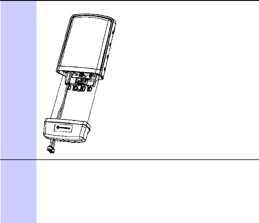
PMP320HDW2v1
2-13
Pr
e
limin
a
r
y
J
UL
2
0
1
0
Earth
Ground
cable
assembly
and
connection
Chapter
2:
AP
Hardware
Installation
Procedure
2-2
Cabling
and
grounding
the
AP
(Continued)
1
Remove
the
connection
protection
casing
using
the
thumb
release
at
the
back
of
the
AP
Unit.
2
Use
dielectric
grease
(which
is
uniformly
non-conducting)
on
all
connections
and
in
all
RJ-45
Ethernet
connectors.
The
best
practice
is
to
use
enough
grease
to
fill
the
RJ-
45
female
connector,
and
then
insert
the
RJ-45
male
connector
and
push
the
grease
further
into
the
unit
and
around
the
RJ-45
connector.
Excess
grease
can
be
wiped
over
the
connector
area
to
provide
some
resistance
to
water
ingress
around
the
connector.
Connect
the
Ethernet
cable
to
the
connector
labeled
ETHERNET
.
Note
that
the
AUX
port
is
not
used
at
this
time.
Continued

2-14
PMP320HDW2v1
Preliminary
JUL
2010
PMP
320
Hardware
Installation
Earth
Ground
cable
assembly
and
connection
Procedure
2-2
Cabling
and
grounding
the
AP
(Continued)
3
Run
a
10
A
WG
ground
strap
from
the
ground
lug
on
the
AP
to
known
good
ground
(Protective
Earth
-
PE).
AP Ground Lug
Ground
the
radio
to
the
tower
.
4
Be
sure
to
reattach
the
bottom
cover
of
the
AP
connection
cover
.
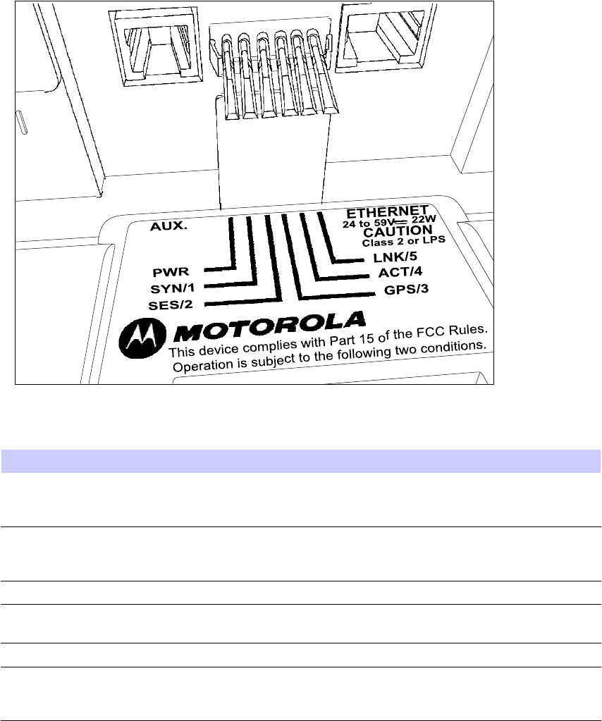
PMP320HDW2v1
2-15
Pr
e
limin
a
r
y
J
UL
2
0
1
0
LED
indicator
Chapter
2:
AP
Hardware
Installation
LED
indicator
The
LED
display
for
the
AP
are
either
Green
or
off
.
Figure
2-3
LED
location
diagram
Table
2-2
LED
indicators
for
the
AP
LED
Description
PWR
(D14)
P
ower
–
green
indicates
the
DC
power
is
on.
This
LED
indicates
that
the
board
is
powered
on.
SYN/1
(D13)
Synchronization
indicator
–
this
indicator
is
on
whenever
the
AP
is
synchronized
with
the
GPS
,
or
when
ever
the
GPS
is
not
used
at
all.
SES/2
(D12)
Not
used,
but
is
always
ON
.
LNK/5
(D9)
GMAC
Ethernet
–
the
LED
is
on
when
the
GMAC
Ethernet
link
is
up.
ACT/4
(D10)
Activity
–
indicates
activity
on
the
ENET
port.
GPS/3
(D11)
GPS
pulse
indicator
–
this
LED
is
on
every
1
pps
interrupt,
and
turned
off
20
frames
after
100
milliseconds).
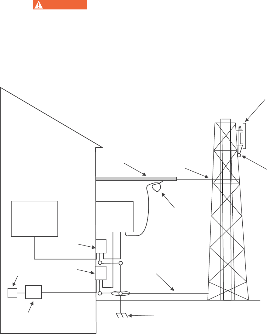
2-16
PMP320HDW2v1
Preliminary
JUL
2010
Attach
the
AP
assembly
to
a
pole
Chapter
2:
AP
Hardware
Installation
Attach
the
AP
assembly
to
a
pole
W
AR
NING
Maintain
a
safe
distance
from
RF
exposure
when
mounting
the
AP
on
the
tower
50
cm
(20
inches).
Maintain
a
safe
distance
from
power
lines.
The
network
planner
should
provide
the
antenna
pattern
information
for
the
installation.
The
network
is
planned
from
true
north
0
degrees.
Use
a
compass
to
ensure
there
is
no
overlap
of
the
antennas
as
they
are
installed.
Figure
2-4
Mounting
the
AP
to
the
tower
AP
Communications
B
l
dg
Cable
Tray
BT-0781S-XXX
BT-0781S-XXX
AP
Grounded
to
Tower
with
10AWG
wire
Network
Switch
or
Router
CMM4
Drip
Loop
600SSD
AC
Power
SGPN4076
200SSB
Tower
Ground
Earth
Ground
Tower
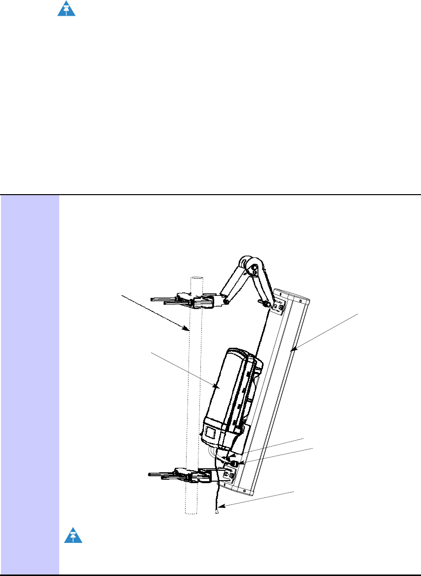
PMP320HDW2v1
2-17
Pr
e
limin
a
r
y
J
UL
2
0
1
0
PMP
320
Hardware
Installation
Attach
the
AP
assembly
to
a
pole
NOTE
•
The
L
-
COM
surge
suppressor
is
used
if
the
Gigabit
Ethernet
port
is
used
in
the
CMM4.
The
L
-
COM
when
used
is
installed
either
in
the
CMM4
cabinet,
or
installed
inside
the
communications
building.
•
This
figure
shows
the
GPS
near
the
top
of
the
AP
unit.
F
or
installation
information
about
the
GPS
refer
to
Installing
the
GPS
Antenna
on
page
3
-
7
.
•
The
AC
line
cord
is
not
provided
with
the
hardware.
This
figure
shows
the
GPS
near
the
top
of
the
AP
unit.
F
or
installation
information
about
the
GPS
refer
to
Installing
the
GPS
Antenna
on
page
3
-
7
.
Procedure
2-3
Attaching
the
AP
assembly
to
a
pole
1
Using
standard
work
and
safety
practices
for
tower
climbing,
connect
the
assembled
unit
(assembled
antenna,
brackets
and
radio)
to
a
pole,
mounting
fixture,
or
a
tower
.
The
unit
must
be
mounted
to
avoid
accidental
touching
by
personnel.
The
standard
mounting
height
is
typically
at
least
4
m
(13
ft)
above
ground
level.
Pole
Is
Shown
For
Reference
Antenna
Radio
(Secured
on
Antenna)
DIV
connector
MAIN
connector
Ethernet
NOTE
Approximate
cable
distance
between
the
AP
and
the
CMM4
is
100
meters.
Continued

2-18
PMP320HDW2v1
Preliminary
JUL
2010
Attach
the
AP
assembly
to
a
pole
Chapter
2:
AP
Hardware
Installation
Procedure
2-3
Attaching
the
AP
assembly
to
a
pole
(Continued)
2
Install
the
top
and
bottom
clamps
to
the
pipe.
Slide
the
clamp
bracket
on
to
the
carriage
bolts.
Slide
on
a
3/8-16
flat
washer
,
3/8-16
split
lock
washer
and
a
3/8-16
hex
nut
to
each
carriage
bolt.
NOTE
•
Align
the
AP
setting
the
desired
downtilt
degree
using
the
inclinometer
.
•
The
network
planner
should
provide
the
antenna
pattern
information
for
the
installation.
The
network
is
planned
from
true
north
0
degrees.
Use
a
compass
to
ensure
there
is
no
overlap
of
the
antennas
as
they
are
installed.
Tighten
the
hex
nut
to
10
ft-lbs
(13.5
N
.m)
after
the
AP
has
been
aligned
to
the
optimum
downtilt
position.
3
Connect
the
Ethernet
cable
from
the
AP
to
the
CMM4
port
controller
.
There
are
up
to
14
ports
in
one
CMM4
switch,
but
only
8
ports
on
the
CMM4
motherboard
that
can
power
up
a
radio
.
Ensure
that
surge
suppression
has
been
installed
for
this
connection.
See
the
section
on
Surge
Suppression
Information.
F
ollow
the
site
plan
created
by
the
network
planner
when
connecting
cables
to
the
CMM4
switch.
Continued
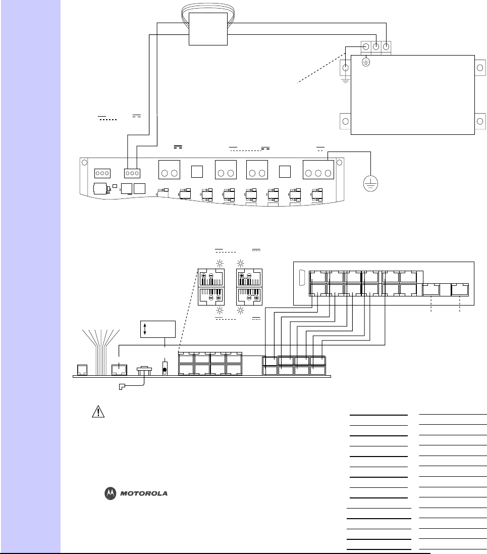
PMP320HDW2v1
2-19
Pr
e
limin
a
r
y
J
UL
2
0
1
0
PMP
320
Hardware
Installation
Attach
the
AP
assembly
to
a
pole
PWR
GND
1 3 5 7 9
11
2 4 6 8 1
0
12
13
1
4
POWER
DEFAULT
GPS_M
ETHERNET
PWR
ACTIVITY
LINK
SYNC
O
K
E
T
GPS
SWITCH
2
4
6 8 4 6 8
3
5 7
3 5 7
Procedure
2-3
Attaching
the
AP
assembly
to
a
pole
(Continued)
TOTAL
20
VDC
ACCESSORY
POWER
IS
NOT
TO
EXCEED
20
WATTS.
ACCESSORY
POWER
OUTPUTS
+20
V
+20
V
Twist
wire
pair
1
twist
per
inch
and
form
three
loops
around
ferrite
core
for
RF
emission
compliance.
Short
wire
to
ChassisGround
at
Switch
mounting
screw
for
RF
emission
compliance.
Green
Black
Red
EtherWAN
Switch
(
Power
Port
View
)
NOTE:
Refer
to
the
System
User
Guide
for
the
power
requirement
of
the
switch
OUTPUT
OUTPUT
specific
to
the
switch
part
number.
GND
(Black)
REDUNDANT
+V
(Red)
+29
V
REDUNDANT
+29
V
+56
V
+56
V
INPUT
INPUT
INPUT
INPUT
GND
GND
+V
GND
GND
+V
+V
GND
+V
GND
+V
GND
+V
GND
PE
CMM4
CONTROLLER
(
Power
Port
View
)
EXTERNAL
PROTECTIVE
EARTH
GROUND
+29
V
+56
V
EtherWAN
Switch
OUTPUT
Red
OUTPUT
Green
RS232
(
Ethernet
Port
View
)
OR
Red
Green
+29
V
+56
V
1000
BaseT
1000
BaseT
DEFAULT
NORMAL
OUTPUT
OUTPUT
AUX
SYNC
ETHERN
TOGGLE
SHIELDED
ETHERNET
CABLES
LEDs
N
Connector
INTERNAL
GPS
CABLE
CMM4
CONTROLLER
(
Ethernet
Port
View
)
MAC
ADDRESS
IP
ADDRESS
TO
GPS
ANTENNA
CAUTION:
Damage
my
result
if
non-approved
equipment
is
connected
to
powered
parts.
IMPORTANT
See
the
System
User
Guide
before
connecting
to
power.
The
Guide
is
available
on-line
at
http://motorola.wirelessbroadbandsupport.com/software/
www.motorola.com
P/N:
5487639D03
CMM4
CONTROLLER
PORT
1
PORT
2
PORT
3
PORT
4
PORT
5
PORT
6
PORT
7
PORT
8
PORT
9
PORT
10
PORT
11
PORT
12
PORT
13
PORT
14
Preliminary
JUL
2010
PMP
320
Hardware
Installation
Surge
Suppression
Information
Surge
Suppression
Information
The
AP
has
metal
-
to
-
metal
contact
from
the
tower
or
support
structure,
through
the
antenna,
through
the
coax
cable,
to
the
radio
.
Installing
surge
suppression
at
the
AP
is
strongly
recommended
to
provide
the
best
protection
from
lightning
strikes.
Up
to
four
600S
SD
surge
suppressors
can
be
mounted
in
series
on
an
Ethernet
link
without
degrading
the
link.
The
equivalent
of
a
600S
SD
is
built
into
each
of
the
8
ports
on
a
CMM4
and
counts
as
one
of
the
four
.
As
an
example,
a
typical
installation
might
have
properly
-
grounded
600S
SD
units
within
3
ft
(1
m)
of
each
AP
and
additional
properly
-
grounded
600S
SD
units
on
each
Ethernet
cable
mounted
outside
at
the
point
of
cable
entry
to
a
telecommunications
hut
that
contains
the
CMM4.
AP
Hardware
Installation
complete
The
AP
hardware
installation
is
complete.
Refer
to
the
PMP
320
Administration
and
Configuration
Guide
to
update
software
or
configure
the
device.
PMP320HDW2v1
2-19
JUL
2010
Preliminary
AP
Hardware
Installation
complete
Chapter
2:
AP
Hardware
Installation
2-20
PMP320HDW2v1

Preliminary
JUL
2010
Chapter
3
CMM4
Hardware
Installation
■ ■ ■ ■ ■ ■ ■ ■ ■ ■ ■ ■ ■ ■ ■ ■ ■ ■ ■ ■ ■ ■ ■ ■ ■ ■ ■ ■ ■ ■ ■ ■ ■ ■ ■
■ ■ ■ ■ ■ ■ ■ ■ ■ ■ ■ ■ ■ ■ ■ ■ ■ ■ ■ ■ ■ ■ ■ ■ ■ ■
■
■
■
■
The
CMM4
consists
of
three
subsystems:
•
the
CMM4
enclosure
and
controller
board
•
power
supplies
•
an
EtherWAN
switch
(mounted
in
the
CMM4
enclosure).
PMP320HDW2v1
3-1
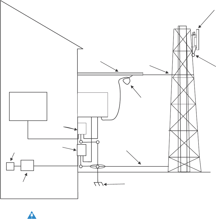
JUL
2010
Preliminary
AP
Hardware
Installation
complete
Chapter
3:
CMM4
Hardware
Installation
Figure
3-1
AP
Installation
and
wiring
AP
Communications
B
l
dg
Cable
Tray
BT-0781S-XXX
BT-0781S-XXX
AP
Grounded
to
Tower
with
10AWG
wire
Network
Switch
or
Router
CMM4
Drip
Loop
600SSD
AC
Power
SGPN4076
200SSB
Tower
Ground
Earth
Ground
Tower
NOTE
•
The
L
-
COM
surge
suppressor
is
used
if
the
Gigabit
Ethernet
port
is
used
in
the
CMM4.
The
L
-
COM
when
used
is
installed
either
in
the
CMM4
cabinet,
or
installed
inside
the
communications
building.
•
This
figure
shows
the
GPS
near
the
top
of
the
AP
unit.
F
or
installation
information
about
the
GPS
refer
to
Installing
the
GPS
Antenna
on
page
3
-
7
.
•
The
AC
line
cord
is
not
provided
with
the
hardware.
3-2
PMP320HDW2v1

3-24
PMP320HDW2v1
Preliminary
JUL
2010
PMP
320
Hardware
Installation
Before
you
begin
Before
you
begin
■ ■ ■ ■ ■ ■ ■ ■ ■ ■ ■ ■ ■ ■ ■ ■ ■ ■ ■ ■ ■ ■ ■ ■ ■ ■ ■ ■ ■ ■ ■ ■ ■ ■ ■
■ ■ ■ ■ ■ ■ ■ ■ ■ ■ ■ ■ ■ ■ ■ ■ ■ ■ ■ ■ ■ ■ ■ ■ ■ ■
■
■
Ensure
that
you
comply
with
standard
local
or
national
electrical
and
climbing
procedures
when
you
install
the
CMM4.
W
AR
NING
Installing
a
CMM
involves
electrical
power
and
can
involve
height
and
exposure
to
RF
(Radio
Frequency)
energy.
To
avoid
personal
injury,
know
and
follow
applicable
national
and
local
safety
regulations
and
industry
best
practices,
and
follow
the
specific
guidelines
in
this
document
If
the
CMM4
is
being
installed
on
a
tower
instead
of
a
communications
hut,
the
operator
will
have
to
calculate
the
wind
loading
on
the
tower
for
the
addition
of
the
CMM4.
Avoiding
Hazards
Use
simple
precautions
to
protect
staff
and
equipment.
Hazards
include
exposure
to
RF
waves,
lightning
strikes,
and
power
surges.
This
section
specifically
recommends
actions
to
abate
these
hazards.
Grounding
Equipment
Effective
lightning
protection
diverts
lightning
current
safely
to
ground,
Protective
Earth
(PE).
It
neither
attracts
nor
prevents
lightning
strikes.

PMP320HDW2v1
3-25
Preliminary
JUL
2010
Grounding
Infrastructure
Equipment
Chapter
3:
CMM4
Hardware
Installation
Grounding
Infrastructure
Equipment
T
o
protect
both
your
staff
and
your
infrastructure
equipment,
implement
lightning
protection
as
follows:
•
Observe
all
local
and
national
codes
that
apply
to
grounding
for
lightning
protection.
•
Before
you
install
your
modules,
perform
the
following
steps:
Engage
a
grounding
professional
if
you
have
any
questions
on
grounding.
Install
lightning
arrestors
to
transport
lightning
strikes
away
from
equipment.
F
or
example,
install
a
lightning
rod
on
a
tower
leg
other
than
the
leg
to
which
you
mount
your
module.
Connect
your
lightning
rod
to
ground.
Plan
to
use
an
appropriate
surge
suppressor
on
any
Ethernet
cable
at
the
point
where
it
enters
any
building
or
structure.
•
Install
your
modules
at
least
2
feet
(0.6
meters)
below
the
tallest
point
on
the
tower
,
pole,
or
roof
.
Conforming
to
Regulations
F
or
all
electrical
purposes,
ensure
that
your
network
conforms
to
applicable
country
and
local
codes,
such
as
the
NEC
(National
Electrical
Code)
in
the
U
.S
.A.
If
you
are
uncertain
of
code
requirements,
engage
the
services
of
a
licensed
electrician.
In
particular
,
many
codes
require
that
wired
electrical
devices
like
the
56
VDC
power
supply
either
terminate
in
a
plug
connection
or
be
wired
with
an
on/off
switch,
and
not
be
hard
-
wired
to
AC/mains.
Protecting
Cables
and
Connections
Cables
that
move
in
the
wind
can
be
damaged,
impart
vibrations
to
the
connected
device,
or
both.
A
t
installation
time,
prevent
these
problems
by
securing
all
cables
with
cable
ties,
cleats,
or
weather
-
resistant
tape.
The
cable
can
be
a
path
for
water
to
follow
to
enter
the
cable
connector
or
even
the
module.
Y
ou
can
prevent
this
problem
by
including
and
securing
a
drip
loop
where
the
cable
enters
the
module
enclosure.
Testing
the
Components
The
best
practice
is
to
connect
all
the
components
-
BHs,
AP
s,
GPS
antenna,
and
CMM4
-
in
a
test
setting
and
initially
configure
and
verify
them
before
deploying
them
to
an
installation.
However,
circumstances
or
local
practice
may
require
a
different
practice.
3-26
PMP320HDW2v1
Preliminary
JUL
2010
PMP
320
Hardware
Installation
Unpacking
Components
Unpacking
Components
When
you
receive
products,
carefully
inspect
all
shipping
boxes
for
signs
of
damage.
If
you
find
damage,
immediately
notify
the
transportation
company
.
As
you
unpack
the
equipment,
verify
that
all
the
components
that
you
ordered
have
arrived.
Save
all
the
packing
materials
to
use
later
,
as
you
transport
the
equipment
to
and
from
installation
sites.

PMP320HDW2v1
3-27
Preliminary
JUL
2010
Installation
Overview
Chapter
3:
CMM4
Hardware
Installation
Installation
Overview
■ ■ ■ ■ ■ ■ ■ ■ ■ ■ ■ ■ ■ ■ ■ ■ ■ ■ ■ ■ ■ ■ ■ ■ ■ ■ ■ ■ ■ ■ ■ ■ ■ ■ ■
■ ■ ■ ■ ■ ■ ■ ■ ■ ■ ■ ■ ■ ■ ■ ■ ■ ■ ■ ■ ■ ■ ■ ■ ■ ■
■
■
Before
beginning
the
physical
installation
of
the
CMM4
hardware
make
sure
the
GUI
configuration
is
completed.
Refer
to
configuration
details
in
the
PMP
320
Administration
and
Configuration
Guide
for
additional
information
on
the
GUI
configuration
procedures.
The
physical
installation
of
the
CMM4
includes
the
following:
•
physically
install
the
CMM
on
the
tower
(or
near
the
communications
hut)
•
physically
install
the
GPS
unit
(included
with
the
CMM4,
does
not
have
to
be
ordered
separately)\
•
physically
install
the
surge
suppressors
•
cable
the
following
CMM4
components:
GPS
P
ower
ENET
600S
SD
surge
suppressor
200SB
surge
suppressor
L
-
COM
surge
suppressor
(if
the
Gigabit
Ethernet
port
is
in
use
at
this
site,
the
L
-
COM
must
be
installed
inside
the
CMM4
unit,
or
inside
the
communication’s
hut,
this
item
is
never
installed
out
doors)
Earth
to
ground

3-28
PMP320HDW2v1
Preliminary
JUL
2010
PMP
320
Hardware
Installation
Installing
the
GPS
Antenna
Installing
the
GPS
Antenna
■ ■ ■ ■ ■ ■ ■ ■ ■ ■ ■ ■ ■ ■ ■ ■ ■ ■ ■ ■ ■ ■ ■ ■ ■ ■ ■ ■ ■ ■ ■ ■ ■ ■ ■
■ ■ ■ ■ ■ ■ ■ ■ ■ ■ ■ ■ ■ ■ ■ ■ ■ ■ ■ ■ ■ ■ ■ ■ ■ ■
■
■
Outside
the
CMM4
enclosure,
the
CMM4
requires
a
GPS
antenna
and
power
suppl
y
.
The
GPS
antenna
must
be
installed
in
an
area
with
clear
access
for
strong
signal
reception,
but
does
not
need
to
be
mounted
high
on
the
tower
.
NOTE
Orient
the
GPS
antenna
so
it
has
clear
access
to
the
southern
horizon,
up
to
20
degrees.
Do
not
install
the
GPS
as
the
highest
object
at
the
site.
Information
on
GPS
cable
planning,
ordering,
and
design
is
covered
in
GPS
Coax
Cable
on
page
3
-
8
.
The
following
information
describes
the
recommended
tools
and
procedures
to
mount
the
GPS
antenna.
Recommended
Tools
for
GPS
Antenna
Mounting
The
following
tools
and
materials
are
needed
for
mounting
the
GPS
antenna:
•
3/8
inch
nut
driver
•
12
inch
adjustable
wrench
•
7/16
inch
wrench
•
Needle
-
nose
pliers
•
electrical
tape
for
all
GPS
connections
•
water
-
tight
tape
for
all
GPS
connections
Mounting
a
GPS
Antenna
P
erform
the
following
procedure
to
mount
a
GPS
antenna.
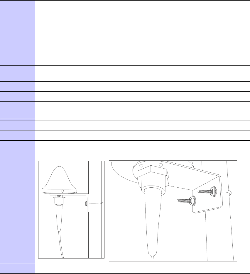
PMP320HDW2v1
3-29
Preliminary
JUL
2010
GPS
Coax
Cable
Chapter
3:
CMM4
Hardware
Installation
Procedure
3-1
Mounting
the
GPS
Antenna
1
Ensure
that
the
mounting
position:
•
has
an
unobstructed
view
of
the
sky
to
20º
above
the
horizon.
•
must
not
be
the
highest
object
on
the
tower
.
(The
GPS
antenna
does
not
need
to
be
particularly
high
on
a
site,
which
would
give
it
more
exposure
to
lightning.
It
just
needs
to
have
an
unobstructed
view
of
the
southern
horizon.)
•
is
not
further
than
100
feet
(30.4
meters)
of
cable
from
the
CMM.
2
Select
a
pole
that
has
an
outside
diameter
of
1.25
to
1.5
inches
(3
to
4
cm)
to
which
the
GPS
antenna
bracket
can
be
mounted.
3
A
ttach
the
GPS
unit
to
the
bracket
using
4
screws.
4
Place
the
U
-bolts
(provided)
around
the
pole.
5
Slide
the
GPS
antenna
bracket
onto
the
U
-bolts.
6
Slide
the
ring
washers
(provided)
onto
the
U
-bolts.
7
Slide
the
lock
washers
(provided)
onto
the
U
-bolts.
8
Use
the
nuts
(provided)
to
securely
fasten
the
bracket
to
the
U
-bolts.
9
Connect
the
GPS
coax
cable
to
the
female
N-connector
on
the
GPS
antenna.
See
the
section
GPS
Coax
Cable
for
additional
details
on
the
length
and
type
of
coaxial
cable
needed.
10
Use
water
type
tape
and
electrical
tape
to
seal
the
connector.
GPS
Coax
Cable
The
operator
provides
the
GPS
antenna
coaxial
cable
between
the
CMM4
and
the
GPS
antenna.
It
must
be
engineered
to
length,
and
is
not
included
with
the
CMM4.
In
most
cases,
the
cable
length
from
the
CMM4
to
the
GPS
antenna
must
be
less
than
30
m
(~100
ft).

3-30
PMP320HDW2v1
Preliminary
JUL
2010
http://best
-
PMP
320
Hardware
Installation
GPS
Coax
Cable
Antenna
cables
can
be
ordered
from
Best
-
Tronics,
Inc.,
.
Antenna
cables
can
be
ordered
in
lengths
up
to
100
ft
(30.4
m).
tronics.com/motorola.htm
Table
3-1
Cable
description
Best-T
ronics
Part
Number
Description
BT
-0564
N
to
N
GPS
antenna
cable
Alternativel
y
,
equivalent
cables
may
be
procured
by
the
operator
,
fabricated
by
the
operator
in
a
depot,
or
fabricated
at
site
using
•
Up
to
100
feet
(30.4
meters)
of
LMR200
coaxial
cable
•
2
Times
Microwave
N
-
male
connectors
(Times
Microwave
P/N
TC
-
200
-
NM)
or
equivalent
connectors
NOTE
The
CMM4
has
a
female
N
-
type
coax
connector
on
the
outside
of
the
enclosure,
whereas
the
CMM
micro
has
a
female
BNC
-
type
connector
inside
the
enclosure.
T
ake
this
into
account
when
ordering
or
fabricating
cables,
and
when
replacing
a
CMM
micro
with
a
CMM4.

PMP320HDW2v1
3-31
Preliminary
JUL
2010
1
Install
the
CMM4
power
supply
in
a
hut,
wiring
closet,
or
weatherized
NEMAapproved
enclosure.
It
is
designed
for
extreme
temperatures
but
it
is
imperative
to
keep
moisture
away
from
the
power
converter
.
2
Do
not
install
the
power
supply
within
the
CMM4
enclosure
as
it
will
increase
the
heat
within
the
enclosure
to
an
unacceptable
level.
The
CMM4
enclosure
is
large
to
provide
surface
area
for
heat
dissipation
without
the
use
of
forced
convection
fans,
not
to
provide
space
for
additional
high-power
electronics.
3
F
or
the
DC
side
of
a
56
VDC
power
suppl
y
,
engineer
the
DC
cable,
selecting
the
wire
gage
from
T
able
4-1
.
Use
either
UV
-resistant
cable
or
shield
the
cable
(as
in
a
conduit)
from
UV
rays.
4
Installing
the
power
supply
for
the
CMM4
Chapter
3:
CMM4
Hardware
Installation
Installing
the
power
supply
for
the
CMM4
■ ■ ■ ■ ■ ■ ■ ■ ■ ■ ■ ■ ■ ■ ■ ■ ■ ■ ■ ■ ■ ■ ■ ■ ■ ■ ■ ■ ■ ■ ■ ■ ■ ■ ■
■ ■ ■ ■ ■ ■ ■ ■ ■ ■ ■ ■ ■ ■ ■ ■ ■ ■ ■ ■ ■ ■ ■ ■ ■ ■
■
■
W
AR
NING
Although
the
output
of
the
power
supply
is
29
VDC
or
56
VDC,
the
power
rating
classifies
the
converter
as
a
Class
2
electric
device.
For
this
reason,
whenever
you
work
on
power
in
the
CMM4,
you
must
first
disconnect
the
DC
supply
from
the
AC
power
source.
Select
the
appropriate
procedure
to
install
the
power
supply
for
the
CMM4.
Directions
are
provided
for
a
56
VDC
power
supply
and
a
procedure
on
how
to
install
the
30
VDC
power
suppl
y
.
If
using
both
30
VDC
and
56
VDC
,
a
1000
Ohm
5W
resistor
must
be
installed
across
the
30
VDC
+V
and
GND
at
the
terminal
block.
56
VDC
Power
Supply
Installation
Use
the
following
procedure
to
install
a
56
VDC
power
supply
for
the
CMM4.
Procedure
3-2
Installing
a
56
VDC
Power
Supply
for
the
CMM4
Connect
the
DC
cable
on
the
top
of
the
connector.
Insert
the
+V
lead
into
the
terminal
7
cage
clamp
and
insert
the
GND
(ground/return)
lead
into
the
terminal
4
cage
clamp.
T
o
insert
a
lead
into
a
cage
clamp,
insert
a
thin-blade
screwdriver
in
the
secondary
cage
clamp
hole
and
lever
the
screwdriver
away
from
the
main
cage
clamp
hole.
Continued
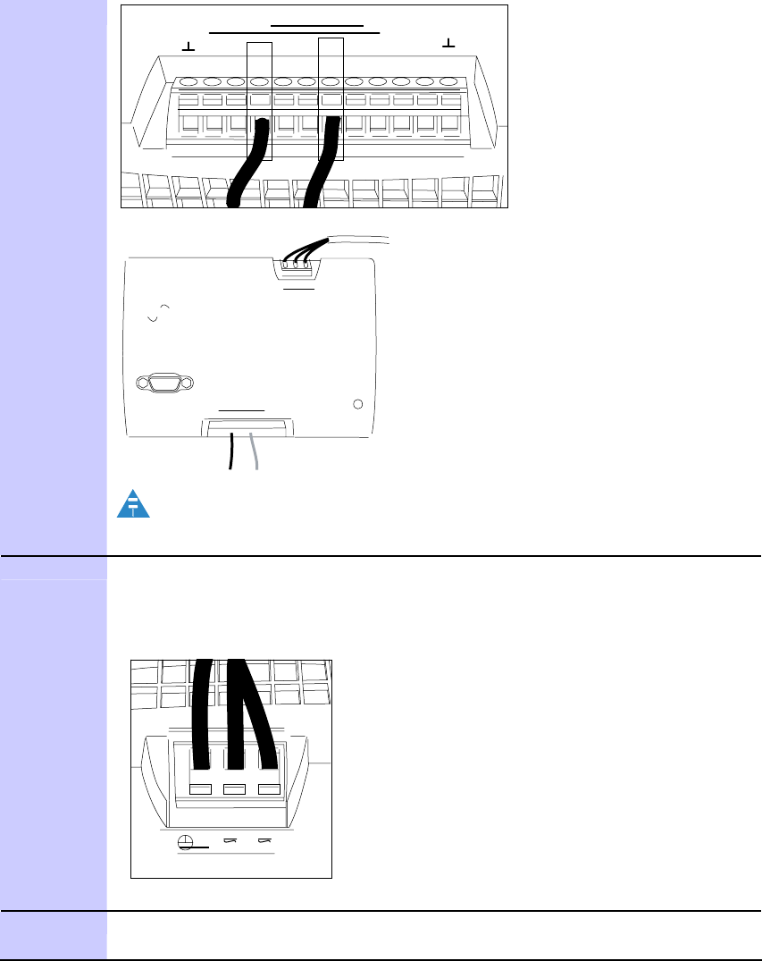
3-32
PMP320HDW2v1
Preliminary
JUL
2010
AUX 2
AUX 1
convert
IN
5
F
or
the
AC
side
of
a
56
VDC
power
suppl
y
,
connect
an
AC
cable
to
the
power
supply
using
Ground/protective
earth,
Neutral
(N),
and
Line
(L).
T
o
insert
a
lead
into
a
cage
clamp,
insert
a
thin-blade
screwdriver
in
the
secondary
cage
clamp
hole
and
lever
the
screwdriver
away
from
the
main
cage
clamp
hole.
1
2
3
N
L
Input
The
AC
line
cord
is
not
provided
with
the
hardware.
6
T
erminate
the
other
end
of
the
AC
cable
to
a
country-specific
AC
connector
or
wire
to
a
switch
in
accordance
with
local
electrical
codes.
AUX
2
AUX
1
PMP
320
Hardware
Installation
56
VDC
Power
Supply
Installation
Procedure
3-2
Installing
a
56
VDC
Power
Supply
for
the
CMM4
(Continued)
Output
+ +
-
-+ +
- -
N
L
Input
power
-one-
OUT
Output
+
+
-
-
+
+
-
-
select
NOTE
AC
connection
on
top,
DC
on
bottom.
PMP320HDW2v1
3-33
Preliminary
JUL
2010
30
VDC
Power
Supply
Installation
Chapter
3:
CMM4
Hardware
Installation
30
VDC
Power
Supply
Installation
If
the
PMP
320
will
be
co
-
located
with
PMP
100
equipment
on
the
same
CMM4,
refer
to
the
Cluster
Management
Module
4
User
Guide
at
http://motorola.wirelessbroadbandsupport.com/
for
additional
information
on
how
to
install
the
30
VDC
power
suppl
y
,
and
the
1000
Ohm
5
W
resistor
that
must
be
installed
along
with
that
power
suppl
y
.
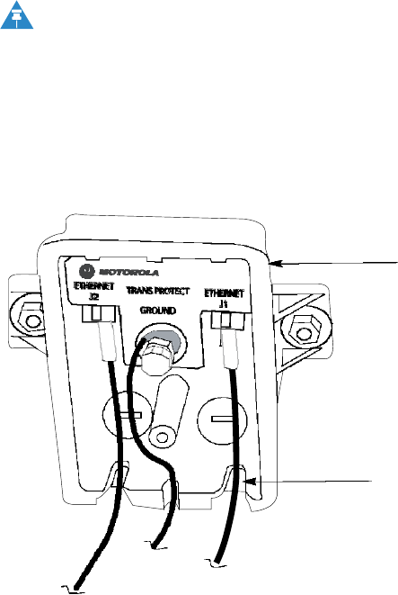
3-34
PMP320HDW2v1
Preliminary
JUL
2010
PMP
320
Hardware
Installation
Surge
Suppressors
Surge
Suppressors
■ ■ ■ ■ ■ ■ ■ ■ ■ ■ ■ ■ ■ ■ ■ ■ ■ ■ ■ ■ ■ ■ ■ ■ ■ ■ ■ ■ ■ ■ ■ ■ ■ ■ ■
■ ■ ■ ■ ■ ■ ■ ■ ■ ■ ■ ■ ■ ■ ■ ■ ■ ■ ■ ■ ■ ■ ■ ■ ■ ■
■
■
The
outdoor
mounting
of
the
CMM4
requires
the
600S
SD
,
200S
SB,
and
in
certain
cases
the
LCOM
surge
suppressor
.
The
L
-
COM
surge
suppressor
is
used
only
if
the
Gigabit
Ethernet
port
is
being
used
on
the
CMM4
switch.
The
L
-
COM
surge
suppressor
can
be
installed
in
the
CMM4
unit.
The
overall
installation
instructions
are
as
follows:
•
ground
the
600S
SD
and
the
200S
SB
to
Earth
Ground
•
connect
the
protected
side
of
the
200S
SB
to
the
AC
power
supply
SGPN4076
•
connect
the
protected
side
of
the
600S
SD
to
the
network
switch
or
router
in
the
communications
hut.
•
add
drip
loops
at
any
point
in
the
cabling
where
the
cable
changes
direction.
NOTE
Additional
L
-
COM
considerations
during
installation:
if
the
CMM4
unit
is
mounted
on
the
antenna
and
is
located
more
that
three
feet
away
from
the
communications
hut,
an
additional
L
-
COM
surge
suppressor
must
be
installed.
Figure
3-2
600SSD
surge
suppressor
connectors
Surge
Suppressor
All
cables
must
exit
through
the
allocated
slots
600SSD
and
200SSB
Surge
Suppressor
installation
Use
the
following
procedure
to
install
the
600S
SD
and
the
200SB
surge
suppressors.

PMP320HDW2v1
3-35
Preliminary
JUL
2010
L-COM
Surge
Suppressor
installation
Chapter
3:
CMM4
Hardware
Installation
CAUT
I
ON
Observe
caution
when
drilling
through
the
wall
of
the
building.
Ensure
that
there
are
no
power
lines,
gas
lines,
water
lines,
or
data
lines
in
the
wall
at
the
desired
location
where
the
drilling
takes
place.
Procedure
3-3
Surge
suppressor
installation
and
cable
connections
1
A
ttach
the
surge
suppressor
to
the
communication
hut
near
the
cable
access
point
to
the
inside
of
the
communications
hut
using
two
screws.
2
Remove
the
surge
suppressor
front
cover
to
access
the
Ethernet
RJ-45
jacks.
3
Connect
the
Ethernet
cable
from
the
CMM4
to
the
Ethernet
port
on
the
surge
suppressor
port.
4
CAUT
I
ON
Follow
local
building
codes
for
penetrating
buildings.
Observe
caution
when
drilling
through
the
wall
of
the
building.
Ensure
that
there
are
no
power
lines,
gas
lines,
water
lines,
or
data
lines
in
the
wall
at
the
desired
location.
Drill
a
3/4
inch
(18
mm)
hole
through
the
wall
of
the
communications
hut
at
the
desired
location.
5
Connect
the
Ethernet
cable
from
the
network
or
switch
router
from
the
communications
hut
to
the
Ethernet
port
on
the
600S
SD
surge
suppressor
.
6
Use
dielectric
grease
(which
is
uniformly
non-conducting)
on
all
connections
and
in
all
RJ-45
Ethernet
connectors.
The
best
practice
is
to
use
enough
grease
to
fill
the
RJ-45
female
connector,
and
then
insert
the
RJ-45
male
connector
and
push
the
grease
further
into
the
unit
and
around
the
RJ-45
connector.
Excess
grease
can
be
wiped
over
the
connector
area
to
provide
some
resistance
to
water
ingress
around
the
connector.
7
Ground
the
surge
suppressor
to
Earth
Ground.
8
Install
the
surge
suppressor
front
cover
to
the
base
of
the
unit
ensuring
that
the
cables
are
all
routed
through
the
cable
slots.
L-COM
Surge
Suppressor
installation
The
L
-
COM
surge
suppressor
is
used
only
when
the
Gigabit
Ethernet
port
is
used
on
the
CMM4
switch.
The
L
-
COM
must
be
installed
inside
the
CMM4
unit,
or
inside
the
communication’s
hut,
this
item
is
never
installed
outdoors.
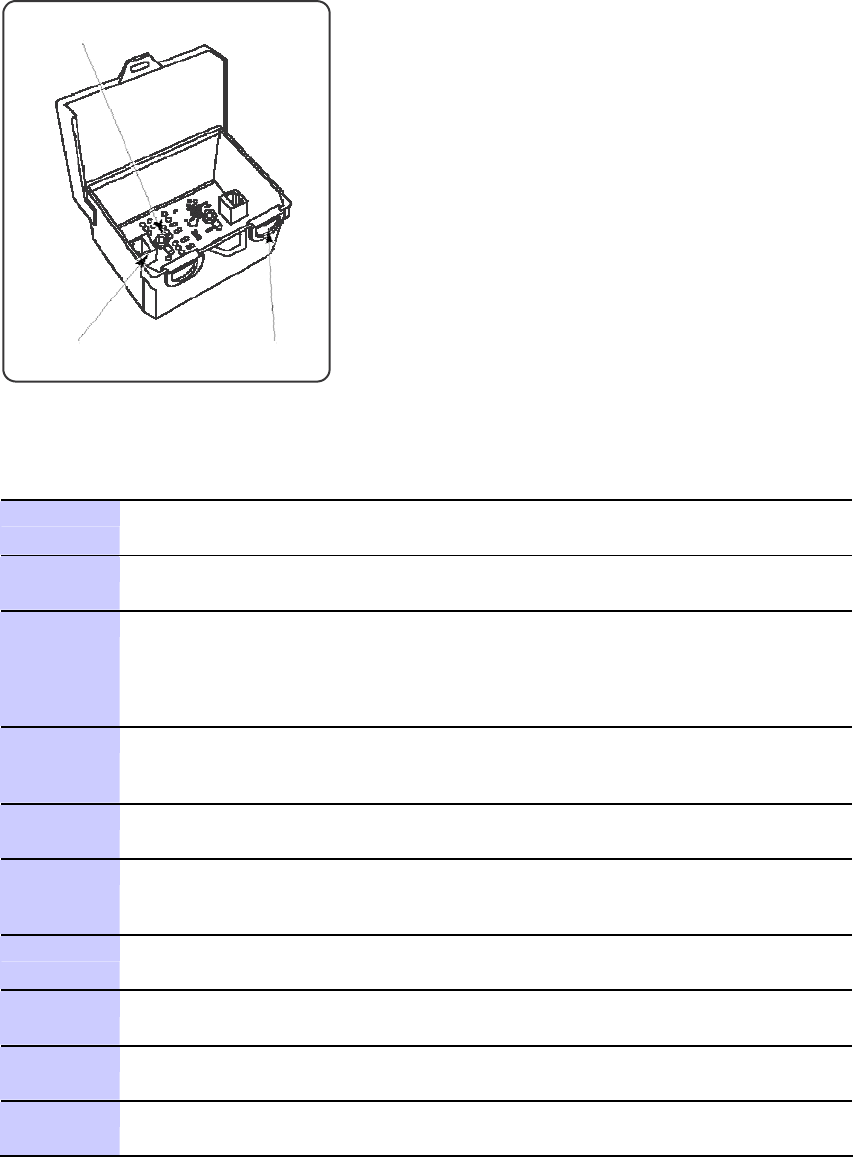
3-36
PMP320HDW2v1
Preliminary
JUL
2010
PMP
320
Hardware
Installation
L-COM
Surge
Suppressor
installation
Figure
3-3
L-COM
surge
suppressor
2X
Grounding
Lugs
and
Te r m i n a l s
Lockable
Hinged
Cover
2X
RJ45
Jacks
2X
Cable
Grommets
Procedure
3-4
L-COM
surge
suppressor
installation
1
Determine
whether
the
L-COM
surge
suppressor
will
be
installed
inside
the
CMM4
unit
or
outside
the
unit.
2
Remove
the
front
cover
of
the
surge
suppressor
to
access
the
Ethernet
RJ-45
jacks.
3
If
the
unit
is
installed:
•
inside
the
CMM4
unit,
continue
to
step
4
.
•
outside
the
CMM4
unit
in
the
communications
hut,
continue
to
step
8
.
4
Place
the
L-COM
surge
suppression
unit
inside
the
CMM4
housing.
Be
careful
not
to
place
the
surge
suppressor
in
the
unit
as
to
crush
any
cables
in
the
CMM4
unit
or
cables
going
through
the
cable
glands.
5
Connect
the
Gigabit
Ethernet
connection
from
the
CMM4
to
the
L-COM
Ethernet
connector.
6
Connect
the
Ethernet
cable
from
the
L-COM
surge
suppressor
and
feed
the
cable
through
the
cable
gland
on
the
CMM4
and
connect
to
the
switch
in
the
communications
hut.
7
Connect
the
Earth
Ground
on
the
surge
suppressor
to
the
Earth
Ground
in
the
CMM4
cabinet,
continue
to
step
13
.
8
Install
the
L-COM
surge
suppressor
inside
the
communications
hut
using
two
screws.
9
Connect
the
Gigabit
Ethernet
cable
to
the
Ethernet
cable
connection
in
the
L-COM
surge
suppressor
.
10
Connect
the
Ethernet
cable
from
the
surge
suppressor
to
the
switch
in
the
communications
hut.
Continued

PMP320HDW2v1
3-37
Preliminary
JUL
2010
L-COM
Surge
Suppressor
installation
Chapter
3:
CMM4
Hardware
Installation
Procedure
3-4
L-COM
surge
suppressor
installation
(Continued)
11
Connect
the
Ethernet
cable
from
the
CMM4
to
the
Ethernet
port
on
the
surge
suppressor
port.
12
Connect
the
surge
suppressor
to
the
Earth
Ground.
13
Place
the
cover
on
the
L-COM
unit
and
attach
the
L-COM
cover
.
3-38
PMP320HDW2v1
Preliminary
JUL
2010
4
User
guide
PMP
320
Hardware
Installation
Installing
the
CMM4
Installing
the
CMM4
■ ■ ■ ■ ■ ■ ■ ■ ■ ■ ■ ■ ■ ■ ■ ■ ■ ■ ■ ■ ■ ■ ■ ■ ■ ■ ■ ■ ■ ■ ■ ■ ■ ■ ■
■ ■ ■ ■ ■ ■ ■ ■ ■ ■ ■ ■ ■ ■ ■ ■ ■ ■ ■ ■ ■ ■ ■ ■ ■ ■
■
■
Install
the
CMM4
outside
only
when
temperatures
are
above
–4°
F
(–20°
C).
The
gland
openings
and
the
bushings
and
inserts
in
the
gland
openings
are
rated
for
the
full
–40°
to
+131°
F
(–40°
to
+55°
C)
range
of
the
CMM4.
However,
for
dynamic
operations
(loosening,
tightening,
and
inserting),
they
are
compliant
at,
and
rated
for
,
only
temperatures
at
or
above
–4°
F
(–20°
C).
F
or
more
information
about
configuring
the
CMM4
device,
refer
to
the
Cluster
Manager
Module
located
at:
.
http://motorola.wirelessbroadbandsupport.com/software/
When
performing
the
installation
of
the
CMM4
unit,
remember
to:
•
install
the
CMM4
outside
the
communications
hut
whenever
possible.
•
do
not
mount
the
power
supply
inside
the
CMM4
enclosure.
•
use
200S
S
for
all
the
DC
cables
powering
the
CMM4.
•
label
all
the
CMM4
connections.
•
do
not
accidentally
toggle
the
default
switch
on
the
CMM4
during
installation.
•
use
the
provided
glands
for
all
connections
for
the
CMM4.
•
Use
drip
loops
at
all
the
transition
points
on
all
cables.
•
Ensure
that
the
pin
4
selector
in
the
surge
suppressor
is
set
isolated
(factory
default).
•
Connect
the
ground
bolt
on
the
CMM4
to
the
Earth
Ground.
•
Run
the
redundant
power
supplies
on
different
paths
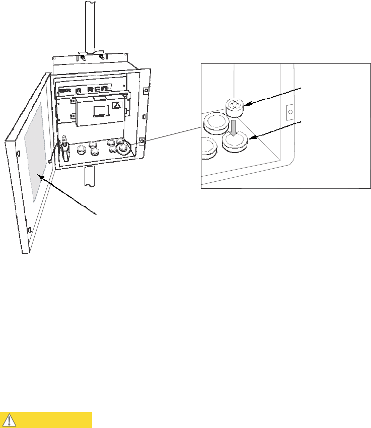
PMP320HDW2v1
3-39
Preliminary
JUL
2010
Installing
the
CMM4
Chapter
3:
CMM4
Hardware
Installation
Figure
3-4
CMM4
unit
opened
showing
connection
details
Cable
Gland
Cable
Housings
Cabling
Diagram
on
Inside
of
Front
Door
Prizm
and
W
ireless
Manager
treat
the
EtherWAN
Switch
in
a
CMM4
as
a
generic
switch.
F
or
Prizm
or
W
ireless
Manager
to
correctly
associate
each
EtherWAN
Switch
with
its
CMM4:
•
before
you
install
the
CMM4,
read
and
note
the
MAC
address
of
both
the
CMM4
controller
and
EtherWAN
switch
from
the
physical
units.
•
after
you
discover
a
CMM4
and
its
switch,
use
these
MAC
addresses
for
moving
the
switch
to
the
place
in
your
Prizm
or
W
ireless
Manager
network
view
where
the
CMM4
was
discovered.
•
always
maintain
a
record
that
associates
these
two
MAC
addresses.
CAUT
I
ON
When
an
EMS
discovers
an
EtherWAN
switch
in
your
network,
it
can’t
tell
which
CMM4
the
switch
is
associated
with,
nor
can
it
tell
CMM4
EtherWAN
switches
from
any
other
EtherWAN
switches
you
may
have
in
your
network.
The
pair
of
MAC
addresses
you
record
directly
from
the
CMM4
and
its
EtherWAN
switch
are
the
only
means
for
you
to
establish
the
logical
connection.
P
erform
the
following
procedure
to
install
the
CMM4.
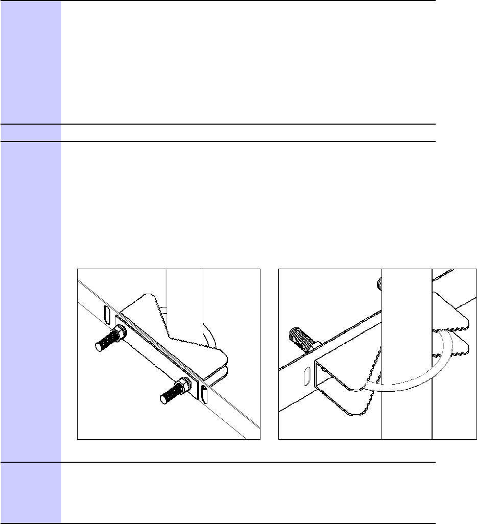
3-40
PMP320HDW2v1
Preliminary
JUL
2010
PMP
320
Hardware
Installation
Installing
the
CMM4
Procedure
3-5
Installing
the
CMM4
1
Ensure
that
the
mounting
position:
•
is
not
farther
than
328
feet
(100
meters)
from
the
furthest
AP
or
BH
that
the
CMM4
will
serve.
•
is
not
closer
than
10
feet
(3
meters)
to
the
nearest
AP
or
BH.
•
is
not
further
than
100
feet
(30.5
meters)
of
cable
from
the
intended
mounting
position
of
the
GPS
antenna.
•
allows
the
doors
to
open
fully
open
for
service.
2
Select
a
support
structure
to
which
the
flanges
can
be
mounted.
3
If
the
support
structure
is:
•
a
wall,
use
screws
or
bolts
(neither
is
provided)
to
attach
the
flanges
to
the
wall.
•
an
irregular-shaped
object,
use
adjustable
stainless
steel
bands
(provided)
to
attach
the
CMM4
to
the
object.
•
a
pole
that
has
an
outside
diameter
of
1.25
to
3
inches
(3
to
8
cm),
use
a
toothed
V
-bracket
(provided)
to
attach
the
V
-bracket
to
the
pole.
Then
attach
the
CMM4
flanges
to
the
V
-bracket.
4
If
the
CMM4
is
mounted
to
a
non-conducting
structure
(cinder
block
wall,
for
example)
or
there
is
any
doubt
as
to
a
good
ground
through
the
structure,
run
a
10
A
WG
ground
cable
from
one
of
the
Ground/Earth
terminations
of
one
of
the
terminal
blocks
inside
the
CMM4,
through
a
cable
gland,
and
to
known
good
ground.
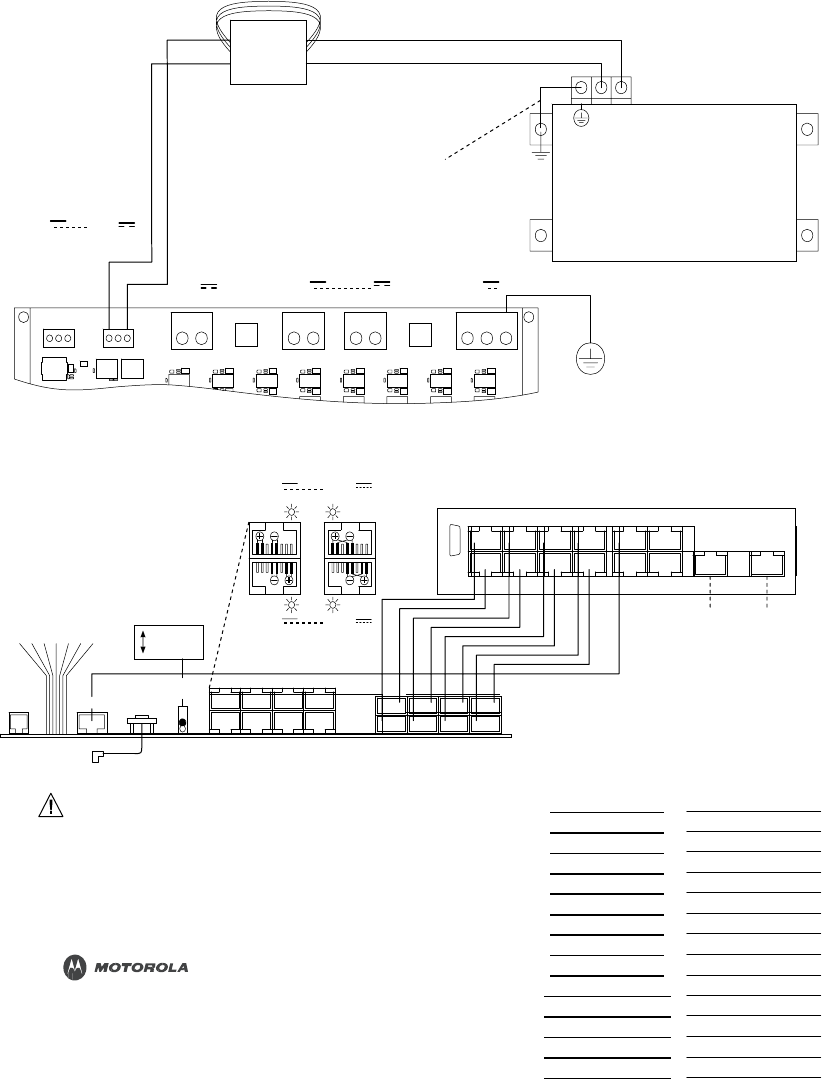
PMP320HDW2v1
3-41
Preliminary
JUL
2010
PWR
GND
1 3 5 7 9
11
2 4 6 8 1
0
12
13
1
4
POWER
DEFAULT
GPS_M
ETHERNET
PWR
ACTIVITY
LINK
SYNC
O
K
E
T
GPS
SWITCH
2
4
6 8 468
3
5 7
3 5 7
Cabling
a
CMM4
Chapter
3:
CMM4
Hardware
Installation
Cabling
a
CMM4
Figure
3-5
CMM4
connection
diagram
located
on
the
door
of
the
unit
TOTAL
20
VDC
ACCESSORY
POWER
IS
NOT
TO
EXCEED
20
WATTS.
ACCESSORY
POWER
OUTPUTS
+20
V
+20
V
Twist
wire
pair
1
twist
per
inch
and
form
three
loops
around
ferrite
core
for
RF
emission
compliance.
Short
wire
to
ChassisGround
at
Switch
mounting
screw
for
RF
emission
compliance.
Green
Black
Red
EtherWAN
Switch
(
Power
Port
View
)
NOTE:
Refer
to
the
System
User
Guide
for
the
power
requirement
of
the
switch
OUTPUT
OUTPUT
specific
to
the
switch
part
number.
GND
(Black)
REDUNDANT
+V
(Red)
+29
V
REDUNDANT
+29
V
+56
V
+56
V
INPUT
INPUT
INPUT
INPUT
GND
GND
+V
GND
GND
+V
+V
GND
+V
GND
+V
GND
+V
GND
PE
CMM4
CONTROLLER
(
Power
Port
View
)
EXTERNAL
PROTECTIVE
EARTH
GROUND
+29
V
+56
V
EtherWAN
Switch
OUTPUT
Red
OUTPUT
Green
RS232
(
Ethernet
Port
View
)
OR
Red
Green
+29
V
+56
V
1000
BaseT
1000
BaseT
DEFAULT
NORMAL
OUTPUT
OUTPUT
AUX
SYNC
ETHERN
TOGGLE
SHIELDED
ETHERNET
CABLES
LEDs
N
Connector
INTERNAL
GPS
CABLE
CMM4
CONTROLLER
(
Ethernet
Port
View
)
MAC
ADDRESS
IP
ADDRESS
TO
GPS
ANTENNA
CAUTION:
Damage
my
result
if
non-approved
equipment
is
connected
to
powered
parts.
IMPORTANT
See
the
System
User
Guide
before
connecting
to
power.
The
Guide
is
available
on-line
at
http://motorola.wirelessbroadbandsupport.com/software/
www.motorola.com
P/N:
5487639D03
CMM4
CONTROLLER
PORT
1
PORT
2
PORT
3
PORT
4
PORT
5
PORT
6
PORT
7
PORT
8
PORT
9
PORT
10
PORT
11
PORT
12
PORT
13
PORT
14
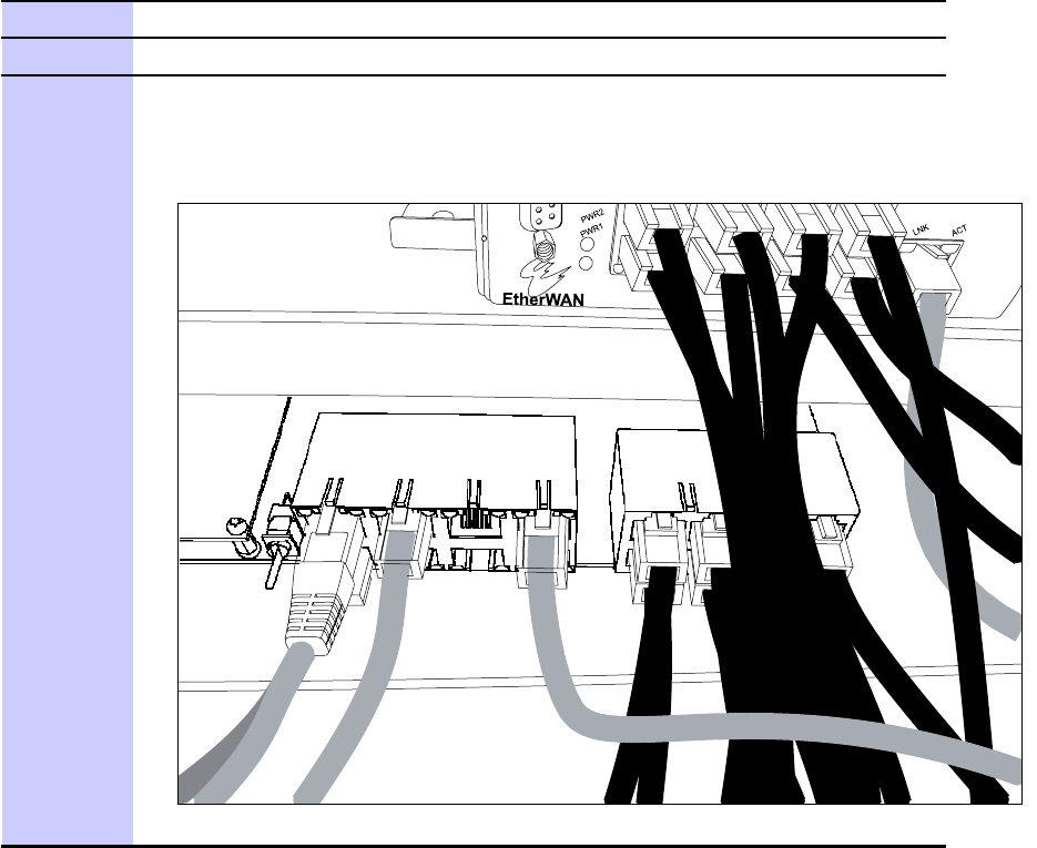
3-42
PMP320HDW2v1
Preliminary
JUL
2010
PMP
320
Hardware
Installation
Cabling
a
CMM4
P
erform
the
following
procedure
to
cable
the
CMM4.
Procedure
3-6
Cabling
the
CMM4
1
Review
the
diagram
inside
the
door
of
the
CMM4.
Refer
to
Figure
3-5
.
2
The
inserts
in
the
gland
openings
of
the
CMM4
have
precut
holes.
3
Route
Ethernet
cables
through
the
cable
gland
connectors
to
the
Ethernet
ports
inside
the
CMM4
cabinet
(see
the
grey
cables
in
the
illustration).
Stagger
the
cables
as
shown
in
the
figure
to
make
it
easier
to
feed
them
through
the
gland.
Continued
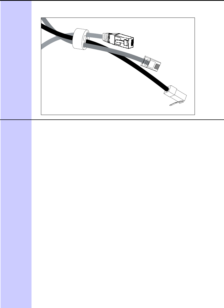
PMP320HDW2v1
3-43
Preliminary
JUL
2010
Cabling
a
CMM4
Chapter
3:
CMM4
Hardware
Installation
Procedure
3-6
Cabling
the
CMM4
(Continued)
4
Stagger
the
cables
as
shown
in
the
figure
to
make
it
easier
to
feed
them
through
the
gland.
5
Connect
Ethernet
cables
as
follows:
•
APs,
BH10s,
or
BH20s
(PTP
100
Series
bridges)
:
cable
to
powered
ports
of
the
controller
board.
The
controller
board
provides
sync,
power,
and
surge
suppression
for
these
connections.
If
the
CMM4
is
mounted
inside
a
building
or
communications
hut,
a
Motorola
600S
SD
surge
suppressor
(model
number
600S
SC
or
later)
should
be
mounted
outside
the
building
or
communications
hut
on
each
line
at
the
point
of
cable
penetration
to
prevent
overvoltages
and
over-currents
from
entering
the
building
and
potentially
damaging
other
electronic
equipment.
•
T
errestrial
feeds
under
100
Mbps
(10/100BaseT)
:
cable
to
an
unpowered
port
of
the
controller
board.
The
controller
board
provides
surge
suppression
for
these
connections.
If
the
CMM4
is
mounted
inside
a
building
or
communications
hut,
a
Motorola
600S
SD
surge
suppressor
(model
number
600S
SC
or
later)
should
be
mounted
outside
the
building
or
communications
hut
on
each
line
at
the
point
of
cable
penetration
to
prevent
over-voltages
and
over-currents
from
entering
the
building
and
potentially
damaging
other
electronic
equipment.
•
T
errestrial
feeds
over
100
Mbps
(1000BaseT
Gigabit
Ethernet)
:
cable
directly
to
the
Gigabit
port
of
the
EtherWAN
switch,
and
mount
a
Motorola
PTP
-LP
U
lightning
protection
unit
or
equivalent
within
3
ft
(1 m)
of
the
CMM4
if
the
CMM4
is
located
outdoors
on
the
outside
of
the
building
or
communications
hut
at
the
point
of
cable
penetration
if
the
CMM4
is
located
indoors.
•
PTP
400
Series
bridges
:
cable
to
an
unpowered
port
of
the
controller
board.
If
the
CMM4
is
inside
a
building
or
communication
hut,
install
the
bridge’s
PIDU
(P
owered
InDoor
Unit)
also
inside
the
building,
and
install
a
Hyperlink
T
echnologies
AL-CA
T6HP
-JW
surge
suppressor
(only
needed
in
special
cases)
or
equivalent
on
the
outside
of
the
building
or
communications
hut
at
the
point
of
cable
penetration.
If
the
CMM4
is
Continued

3-44
PMP320HDW2v1
Preliminary
JUL
2010
6
On
the
door
label,
record
the
MAC
and
IP
addresses
of
the
CMM4
and
all
connected
equipment.
7
Record
also
the
MAC
address
of
the
EtherWAN
switch.
8
Consistent
with
practices
in
your
company
,
note
the
above
information
to
add
later
to
the
company
equipment
database.
9
Connect
the
coax
cable
from
the
female
N-connector
on
the
GPS
antenna
to
the
female
N-connector
on
the
outside
of
the
CMM4.
10
Ensure
there
is
an
Ethernet
cable
between
the
management
port
on
the
controller
board
and
one
of
the
Ethernet
ports
on
the
EtherWAN
switch.
11
F
eed
the
DC
power
cord
through
a
cable
gland.
A
1-hole
gland
insert
is
provided,
as
the
DC
power
cable
is
too
thick
to
share
a
gland
with
other
cables.
The
1-hole
insert
is
either
connected
to
one
of
the
patch
cables
or
included
in
the
parts
bag.
12
Connecting
power
to
the
terminal
block:
•
F
or
29
V
:
Connect
the
white
wire
to
+29V
on
either
of
the
29
VDC
terminal
blocks.
Connect
the
black
wire
to
−V
(GND)
on
the
same
29
VDC
terminal
block.
•
F
or
56V
:
Connect
the
black
and
white
wire
to
+56V
on
either
of
the
56
VDC
terminal
blocks.
Connect
the
black
wire
to
–V
(GND)
on
the
same
56
VDC
terminal
block.
13
Plug
the
DC
power
supply
into
an
AC
receptacle
(AC
mains).
NOTE
The
AC
line
cord
is
not
provided
with
the
hardware.
14
V
erify
that
the
LEDs
light.
PMP
320
Hardware
Installation
LED
indicators
Procedure
3-6
Cabling
the
CMM4
(Continued)
mounted
outside,
locate
the
PIDU
in
a
weather-tight
enclosure
within
3
ft
(1
m)
of
the
CMM4
and
install
a
Hyperlink
T
echnologies
AL-CA
T6HP
-JW
surge
suppressor
or
equivalent
within
3
ft
(1
m)
of
the
PIDU
.
•
PTP
500
and
600
Series
bridges
:
cable
directly
to
the
Gigabit
port
of
the
EtherWAN
switch.
If
the
CMM4
is
inside
a
building
or
communication
hut,
install
the
bridge’s
PIDU
(P
owered
InDoor
Unit)
also
inside
the
building,
and
install
a
Hyperlink
T
echnologies
AL-CA
T6HP
-JW
surge
suppressor
or
equivalent
on
the
outside
of
the
building
or
communications
hut
at
the
point
of
cable
penetration.
If
the
CMM4
is
mounted
outside,
locate
the
PIDU
in
a
weather-tight
enclosure
within
3
ft
(1
m)
of
the
CMM4
and
install
a
Hyperlink
T
echnologies
AL-CA
T6HP
-JW
surge
suppressor
or
equivalent
within
3
ft
(1
m)
of
the
PIDU
.
LED
indicators
The
indicator
LEDs
color
indicates
position,
but
not
the
state.
F
or
example,
the
red
P
ower
LED
,
in
the
left
most
position,
lights
when
power
is
applied
to
the
unit,
but
does
not
change
color
at
any
point.

PMP320HDW2v1
3-45
Preliminary
JUL
2010
Power
Faults
Chapter
3:
CMM4
Hardware
Installation
Table
3-2
LED
Indicators
for
the
CMM4
LED
Color
Item
Red
P
ower
Amber
Default
Green
GPS
Master
Red
Ethernet
Switch
P
ower
Amber
Link
Green
Activity
Amber
Sync
OK
CAUT
I
ON
Surge
suppressors
should
be
installed
on
any
cables
where
they
enter
a
building
to
reduce
the
possibility
of
over
voltages
or
over
currents
damaging
any
equipment
in
the
building.
The
following
equipment,
mounted
outside
of
a
communications
hut
or
building
at
the
point
where
the
cables
penetrate
the
building,
is
recommended:
•
Motorola
600S
SD
surge
suppressors
for
Ethernet
cables
•
Motorola
200S
S
surge
suppressors
for
DC
cables
•
A
P
olyPhaser
DGXZ+06NFNF
-
A
surge
suppressor
for
the
coaxial
cable
from
the
GPS
antenna
Power
Faults
If
excessive
current
is
drawn
on
a
port,
the
analog
circuitry
reports
a
P
oE
fault.
The
system
then
turns
the
port
power
off
.
The
power
will
be
restored
when
the
fault
is
removed.
The
following
illustration
shows
the
port
status
screen
with
a
power
fault
on
port
1.
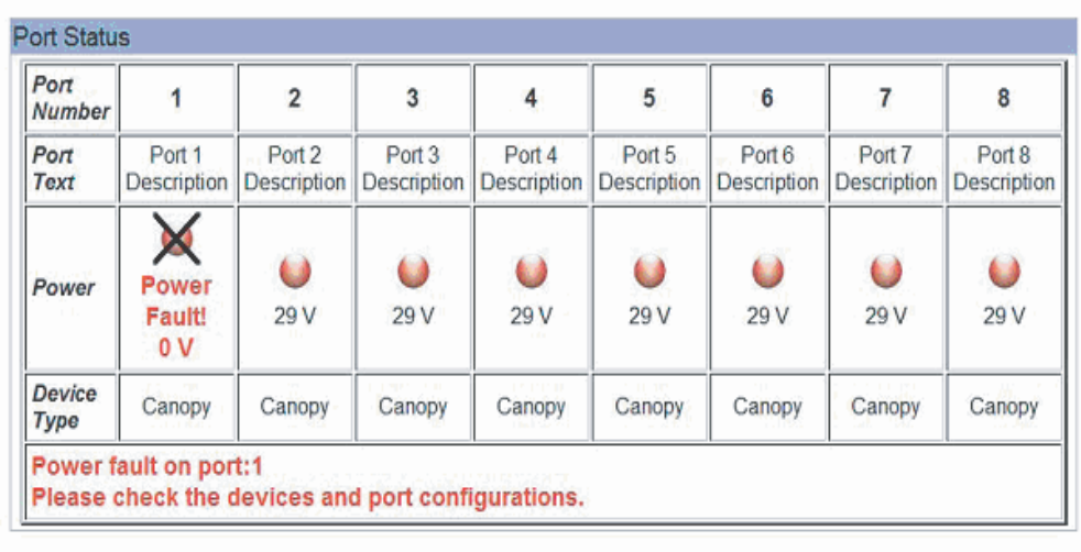
Preliminary
JUL
2010
CMM4
User
Guide
PMP
320
Hardware
Installation
Configuring
CMM4
ports
Figure
3-6
Port
Status
Showing
Power
Fault
Configuring
CMM4
ports
T
o
configure
the
ports
that
have
been
connected
in
this
installation
procedure,
refer
to
the
located
at:
.
http://motorola.wirelessbroadbandsupport.com/software/
Other
Installation
Considerations
If
two
CMM4
devices
are
synchronized
together
,
the
CMM4
that
does
not
have
a
GPS
needs
to
be
set
up
via
the
GUI
as
a
CMM
slave
device.
Refer
to
the
CMM4
User
guide
located
at
:
.
http://motorola.wirelessbroadbandsupport.com/software/
PMP320HDW2v1
3-47
J
UL
2
0
1
0
Pr
e
limin
a
r
y
Other
Installation
Considerations
Chapter
3:
CMM4
Hardware
Installation
3-26
PMP320HDW2v1

Preliminary
JUL
2010
Chapter
4
Cables
■ ■ ■ ■ ■ ■ ■ ■ ■ ■ ■ ■ ■ ■ ■ ■ ■ ■ ■ ■ ■ ■ ■ ■ ■ ■ ■ ■ ■ ■ ■ ■ ■ ■ ■
■ ■ ■ ■ ■ ■ ■ ■ ■ ■ ■ ■ ■ ■ ■ ■ ■ ■ ■ ■ ■ ■ ■ ■ ■ ■
■
■
■
■

PMP320HDW2v1
3-49
J
UL
2
0
1
0
Pr
e
limin
a
r
y
DC
Cables
Chapter
4:
Cables
DC
Cables
■ ■ ■ ■ ■ ■ ■ ■ ■ ■ ■ ■ ■ ■ ■ ■ ■ ■ ■ ■ ■ ■ ■ ■ ■ ■ ■ ■ ■ ■ ■ ■ ■ ■ ■
■ ■ ■ ■ ■ ■ ■ ■ ■ ■ ■ ■ ■ ■ ■ ■ ■ ■ ■ ■ ■ ■ ■ ■ ■ ■
■
■
Motorola
recommends
the
use
of
flame
-
retardant,
moisture
and
sunlight
-
resistant
cable
rated
to
75°
C
wet
and
bendable
at
-
25°
C
for
the
DC
cable
between
the
power
supply(s)
and
the
http://www
),
catalog
CMM4.
Examples
of
such
cable
include
General
Cable
(
.generalcable.com
number
234580
for
12
A
WG
cable
and
catalog
number
236300
for
10
A
WG
cable,
found
in
the
T
elecommunications
Catalog.
Recommended
wire
size
for
the
DC
cable
of
the
CMM4
in
most
systems
is
shown
in
T
able
4
-
1
.
These
wire
sizes
support
up
to
8
radios
(30
VDC
or
56
VDC
radios)
at
up
to
100
m
(328
ft)
Ethernet
cable
length
from
the
CMM4.
Table
4-1
Wire
size
for
CMM4
DC
cable
DC
Power
Cord
Length
W
ire
Gage
Up
to
90
ft
(3−25
m)
12
A
WG
(4
mm
2
)
91−145
ft
(26−45
m)
10
A
WG
(6
mm
2
)
146−230
ft
(46−70
m)
8
A
WG
(10
mm
2
)
F
or
supporting
8
PMP
54400
AP
s
or
PTP
54200
BHs
(which
are
12
W
30
VDC
radios),
reduce
either
the
maximum
DC
cable
length
or
the
Ethernet
cable
length
by
half
.
F
or
example,
if
the
Ethernet
cable
length
from
CMM4
to
8
PMP
54400
AP
s
is
50
m
(164
ft)
or
less,
the
DC
lengths
in
T
able
4
-
1
can
be
used.
If
the
Ethernet
cable
length
from
CMM4
to
8
PMP
54400
AP
s
is
100
m
(328
ft),
then
halve
the
lengths
shown
in
T
able
4
-
1
.
4-2
PMP320HDW2v1

4-50
PMP320HDW2v1
Preliminary
JUL
2010
PMP
320
Hardware
Installation
Ethernet
Cables
Ethernet
Cables
■ ■ ■ ■ ■ ■ ■ ■ ■ ■ ■ ■ ■ ■ ■ ■ ■ ■ ■ ■ ■ ■ ■ ■ ■ ■ ■ ■ ■ ■ ■ ■ ■ ■ ■
■ ■ ■ ■ ■ ■ ■ ■ ■ ■ ■ ■ ■ ■ ■ ■ ■ ■ ■ ■ ■ ■ ■ ■ ■ ■
■
■
The
operator
provides
the
Ethernet
cables
between
the
CMM4
and
the
radios
it
supports.
They
must
be
engineered
to
length
and
are
not
included
with
the
CMM4.
The
cable
length
from
the
CMM4
to
any
radio
must
be
under
100
m
(328
ft).
Cables
are
available
from
Best
-
Tronics,
Inc.,
http://best
-
tronics.com/motorola.htm
.
These
cables
can
be
ordered
in
lengths
up
to
328
ft
(100
m)
and
are
listed
in
the
following
tables.
Table
4-2
Recommended
Ethernet
Cables
T
ypical
Use
Best-T
ronics
Part
Number
Description
Infrastructure
Ethernet
cable
Infrastructure
Ethernet
cable
for
plenums
BT
-0781S
-
XXX
RJ-45
to
RJ-45
straight,
shielded,
UV
-resistant
Ethernet
cable
using
outdoor
STP
Cat
5e
cable,
lower
cost
than
plenum-rated,
available
only
in
black.
BT
-0562S
-
XXX
RJ-45
to
RJ-45
straight,
shielded,
UV
-resistant,
plenum-rated
Ethernet
cable
using
outdoor
STP
Cat
5e
cable,
available
in
beige,
blue,
gre
y
,
or
white.
NOTE
Shielded
Ethernet
cable
is
strongly
recommended
for
AP
and
BH
installations.
Alternativel
y
,
equivalent
cables
may
be
procured
by
the
operator
,
fabricated
by
the
operator
in
a
depot,
or
fabricated
at
site.
The
modules
have
auto
MDX/MDIX
and
so
either
straight
-
through
or
crossover
Ethernet
cables
may
be
used.
Pinouts
for
straight
-
through
cables
are
shown
the
following
figures.
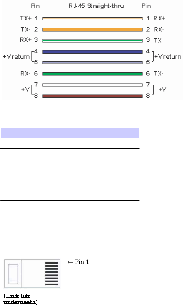
PMP320HDW2v1
4-51
Preliminary
JUL
2010
Ethernet
Cables
Chapter
4:
Cables
Figure
4-1
RJ-45
Straight-through
connections
Table
4-3
Recommended
Ethernet
Cables
Pin
Color
1
white
/
orange
2
orange
3
white
/
green
4
blue
5
white
/
blue
6
green
7
white
/
brown
8
brown
Figure
4-2
Pin
1
Location
diagram
Lo c k t a b
u n d e r n e a t h )
←
P in 1
Bulk
unterminated
Ethernet
cable
can
be
ordered
from
Best
-
Tronics
as
bulk
cable:
•
CA
-
0287S:
(shielded,
plenum
rated)
•
CA
-
0367S:
(lower
cost,
shielded,
non
-
plenum
-
rated)

4-52
PMP320HDW2v1
Preliminary
JUL
2010
PMP
320
Hardware
Installation
CMM
Sync
Cable
CMM
Sync
Cable
■ ■ ■ ■ ■ ■ ■ ■ ■ ■ ■ ■ ■ ■ ■ ■ ■ ■ ■ ■ ■ ■ ■ ■ ■ ■ ■ ■ ■ ■ ■ ■ ■ ■ ■
■ ■ ■ ■ ■ ■ ■ ■ ■ ■ ■ ■ ■ ■ ■ ■ ■ ■ ■ ■ ■ ■ ■ ■ ■ ■
■
■
T
wo
CMMs
(two
CMMmicros,
two
CMM4s,
or
a
CMMmicro
and
a
CMM4)
can
be
connected
together
with
a
CMM
sync
cable
to
provide
either
•
The
ability
to
have
one
GPS
antenna
support
two
CMMs
•
W
arm
spare
redundant
sync
Pinouts
for
the
CMM
sync
cable
are
shown
in
the
following
figures.
Figure
4
-
4
shows
the
location
of
Pin
1,
relative
to
the
lock
tab
on
the
connector.
NOTE
The
CMM
sync
cable
used
to
connect
two
CMMs
for
sync
purposes
has
different
pinouts
than
the
straight
-
through
sync
cable
used
to
connect
a
“remote
AP”
to
an
SM,
or
an
AP
or
BHM
to
a
CMM2.
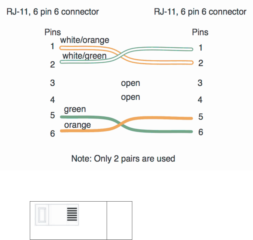
PMP320HDW2v1
4-53
Preliminary
JUL
2010
CMM
Sync
Cable
Chapter
4:
Cables
Figure
4-3
CMM
sync
cable
pinouts
Figure
4-4
CMM
sync
cable
pinouts
(Lock tab is on other side)
←
Pin 1
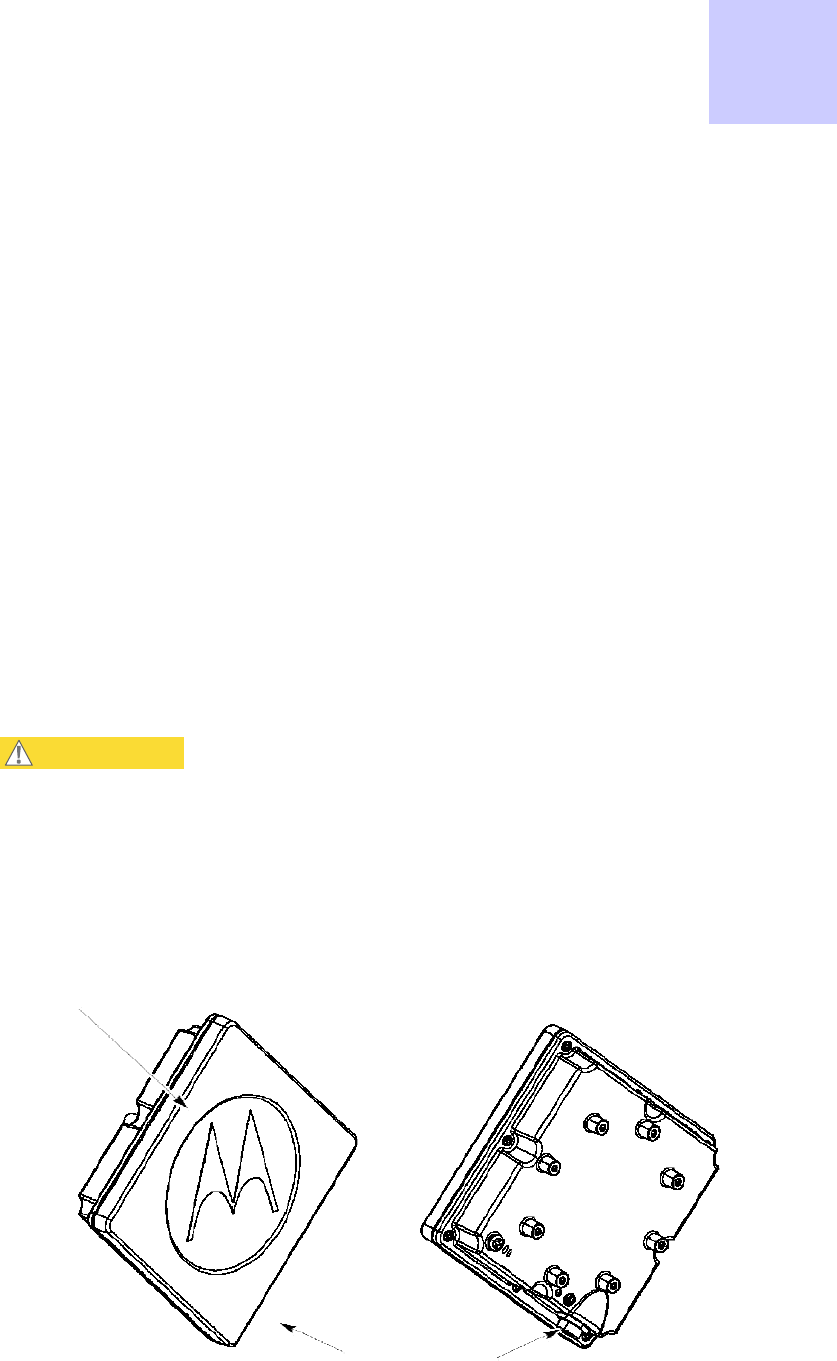
Chapter
5
CSM
Hardware
Installation
■ ■ ■ ■ ■ ■ ■ ■ ■ ■ ■ ■ ■ ■ ■ ■ ■ ■ ■ ■ ■ ■ ■ ■ ■ ■ ■ ■ ■ ■ ■ ■ ■ ■ ■
■ ■ ■ ■ ■ ■ ■ ■ ■ ■ ■ ■ ■ ■ ■ ■ ■ ■ ■ ■ ■ ■ ■ ■ ■ ■
■
■
■
■
This
chapter
provides
the
instructions
and
procedures
used
to:
•
connect
the
CSM
device
to
a
pole
or
wall
•
pre
-
power
up
alignment
for
level
of
service
connection
•
cable
the
unit
•
ground
the
unit
•
add
surge
suppression
•
post
power
up
connection
•
IP
connectivity
alignment
correction
CAUT
I
ON
The
orientation
of
the
CSM
when
installed
is
important.
The
face
of
the
CSM
with the
Motorola
logo
must
be
pointing
in
the
direction
of
the
antenna
facing
outwards from
the
building.
The
Ethernet
connector
must
be
oriented
so
it
is
on
the
bottom
right
corner
of
the
CSM.
Figure
5-1
CSM
(CPE)
320
Identification
Canopy
CSM
320
Ethernet
Connector
Front
Rear
PMP320HDW2v1
5-1
JUL
2010
Preliminary

5-2
PMP320HDW2v1
Preliminary
JUL
2010
Before
you
begin
Chapter
5:
CSM
Hardware
Installation
Before
you
begin
■ ■ ■ ■ ■ ■ ■ ■ ■ ■ ■ ■ ■ ■ ■ ■ ■ ■ ■ ■ ■ ■ ■ ■ ■ ■ ■ ■ ■ ■ ■ ■ ■ ■ ■
■ ■ ■ ■ ■ ■ ■ ■ ■ ■ ■ ■ ■ ■ ■ ■ ■ ■ ■ ■ ■ ■ ■ ■ ■ ■
■
■
This
section
describes
items
that
the
installer
or
subscriber
must
purchase
before
installing
the
CSM.
This
section
also
describes
items
that
must
be
available
and
points
to
consider
before
beginning
the
CSM
installation.
Additional
material
required
for
installation
The
additional
materials
required
for
installation
are
as
follows:
•
The
computer
of
the
subscriber
must
be
equipped
with
an
Ethernet
network
interface
card
(NIC).
NOTE
The
NIC
is
not
provided
with
the
CSM,
but
subscribers
can
purchase
a
NIC
at
most
computer
and
electronics
stores.
•
An
RJ–45
Ethernet
cable
to
connect
the
CSM
plug
-
in
power
supply
to
the
computer
.
•
Ground
wire
of
sufficient
length
to
run
between
the
CSM
and
the
home
ground
point.
NOTE
•
It
is
recommended
that
the
ground
wire
be
a
6
A
WG
,
solid
copper
wire.
•
It
is
recommended
that
if
a
ground
rod
is
used
it
should
be
an
8
ft
(2.5m)
copper
rod.
•
Most
buildings
have
an
existing
ground
rod
outside,
at
the
main
power
connection
site.
If
desired,
a
rod
can
be
installed
into
the
ground
outside
the
building
after
consulting
the
local
electrical
codes.
•
The
AC
line
cord
is
not
provided
with
the
hardware.
Acquire
the
appropriate
power
line
cord
for
the
country
where
the
unit
is
installed.
•
Lead
screw
anchors
if
the
CSM
is
mounted
on
a
brick
or
masonry
surface.
•
Outdoor
-
rated
category
5e
Ethernet
cable
to
connect
the
CSM
plug
-
in
power
supply
through
the
building
wall
to
the
CSM.
•
RJ–45
plug
connectors
and
the
tools
required
for
field
termination
of
the
category
5e
cable
•
Grommet
to
cover
a
3/4
inch.
(18
mm)
hole
•
Silicone
or
acrylic
caulking

PMP320HDW2v1
5-3
Pr
e
limin
a
r
y
J
UL
2
0
1
0
PMP
320
Hardware
Installation
Pre-installation
planning
Pre-installation
planning
While
on
the
ground,
find
an
appropriate
location
outside
the
building
to
mount
the
CSM.
NOTE
T
o
provide
Internet
service,
the
CSM
communicates
with
a
base
station
on
the
communications
tower
of
the
service
provider
.
Information
about
the
nearest
communications
tower
is
provided
by
the
service
provider
.
F
or
example,
if
the
tower
nearest
to
the
building
is
towards
the
north
of
the
building,
install
the
CSM
on
the
north
side
of
the
building.
After determining the optimal side of the building, select an CSM mounting point at a high location is
unlikely to be touched by user/passer on the building such as under the eaves.
Components
shipped
with
the
CSM
Locate
the
components
shipped
with
the
CSM
device.
The
parts
list
for
the
CSM
installation
consists
of
the
following
items:
Table
5-1
CSM
parts
list
Component
Quantity
CSM
320
device
(vertical)
1
Bracket
base
mounting
1
Bracket
Bottom
Mounting
1
Bracket
T
op
Mounting
1
Middle
mounting
bracket
1
M8
(50
mm)
hex
head
bolt
2
M8
(100
mm)
bolt
2
M8
split
washer
13
M8
washer
11
M8
nut
3
M5
(35
mm)
set
screw
2
M4
(16
mm)
bolt
4
M4
split
washer
4
M4
washer
4
Dsign
power
supply
1
ENET
cable
1
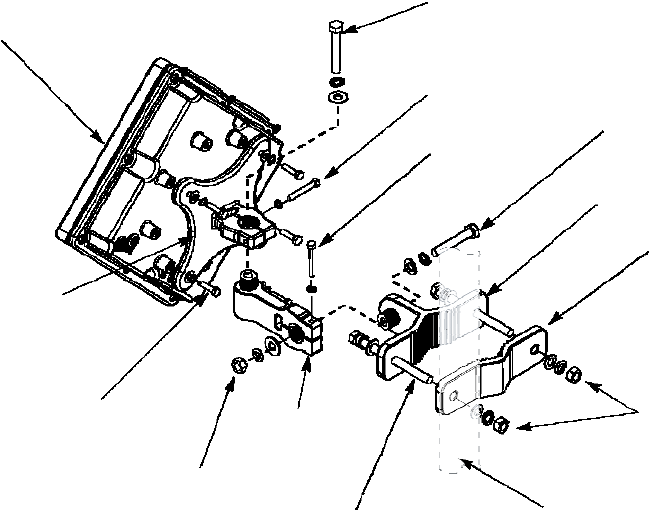
5-4
PMP320HDW2v1
Preliminary
JUL
2010
Cabling
Overview
Chapter
5:
CSM
Hardware
Installation
Figure
5-2
CSM
components
CSM320
M8
x
50
MM
Bolt
M8
Split
Washer
M8
Washer
M5
Set
Screw
35MM
M8
Split
Washer
M5
Set
Screw
35MM
M8
Split
Washer
M8
x
50
MM
Bolt
M8
Split
Washer
M8
Washer
Bracket
Bottom
Mounting
Bracket
Top
Mounting
Bracket
Base
Mounting
4X
M4
x
16MM
Bolt
4X
M4
Split
Washer
4X
M4
Washer
M8
Nut
Middle
Mounting
bracket
2X
M8
Nut
4X
M8
Split
Washer
4X
M8
Washer
M8
Split
Washer
M8
Washer
2X
M8
x
100
MM
Bolt
Mounting
Pole
(Reference)
Cabling
Overview
The
following
items
are
not
supplied
with
the
system:
•
Ground
wire
•
Grounding
rod
•
Outdoor
power/Ethernet
cable
•
Ethernet
cable
•
Computer
NIC
Figure
6
-
4
illustrates
the
routing
of
the
ground
wire,
the
category
5e
Ethernet
cable,
and
the
CSM
power/Ethernet
cable.
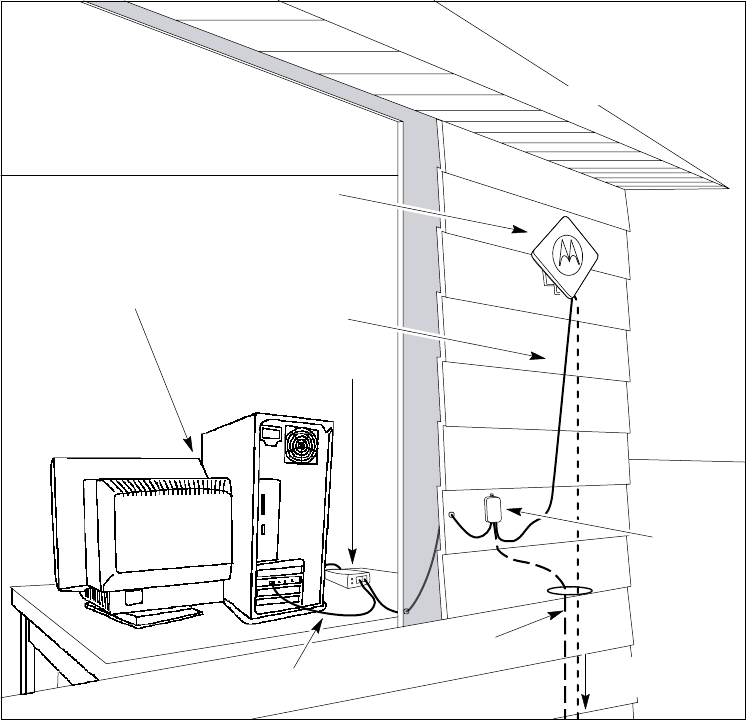
PMP320HDW2v1
5-5
Pr
e
limin
a
r
y
J
UL
2
0
1
0
Building’s
wall
PMP
320
Hardware
Installation
Cabling
Overview
Figure
5-3
CSM
mounted
to
a
wall
Building’s
Roof
CPE
Bracket
assembly
attached
to
building's
exterior
Subscriber’s
Computer
CPE
Power/Ethernet
cable
Dsine
Surge
Suppressor
Etherne
t
cable
(no
t
supplied)
Ground
wire
(no
t
supplied)
t
o
household
grounding
point

5-6
PMP320HDW2v1
Preliminary
JUL
2010
1
Using
a
laptop
and
a
temporary
power
source
connected
to
the
CSM
locate
the
optimal
site
for
the
CSM
to
be
installed.
Refer
to
the
PMP
320
Administration
and
Configuration
Guide
for
additional
information
on
accessing
the
CSM
GUI
and
status
settings.
htt
// t l i l b db d t / t/lib /? i 1& t
2
Start
by
pointing
the
front
of
the
CSM
in
the
direction
that
is
most
likely
to
be
optimal.
3
Try
pointing
the
CSM
in
different
directions.
If
required,
perform
this
task
while
standing
in
the
upper
stories
or
on
the
roof
of
the
building.
A
t
each
elevation
and
in
each
direction
the
CSM
is
pointed.
4
A
fter
determining
the
place
where
the
best
signal
can
be
detected
using
the
CSM
GUI
screen
information,
choose
a
corresponding
CSM
installation
location
on
the
building.
NOTE
The
CSM
can
be
mounted
either
directly
on
the
building
or
on
a
pole.
Installing
the
CSM
Chapter
5:
CSM
Hardware
Installation
Installing
the
CSM
■ ■ ■ ■ ■ ■ ■ ■ ■ ■ ■ ■ ■ ■ ■ ■ ■ ■ ■ ■ ■ ■ ■ ■ ■ ■ ■ ■ ■ ■ ■ ■ ■ ■ ■
■ ■ ■ ■ ■ ■ ■ ■ ■ ■ ■ ■ ■ ■ ■ ■ ■ ■ ■ ■ ■ ■ ■ ■ ■ ■
■
■
This
section
describes
how
to
find
an
appropriate
installation
location
for
the
CSM,
and
how
to
install
the
CSM
on
the
building.
Selecting
a
location
for
the
CSM
Determine
the
optimum
installation
location
for
the
CSM
before
physically
mounting
the
CSM
to
the
building.
Most
often,
if
the
CSM
is
mounted
on
the
side
of
the
building
facing
the
base
station
of
the
service
provider
,
the
CSM
can
detect
adequate
signal
to
provide
high
-
speed
Internet
access.
However,
unless
there
is
an
obvious
line
of
sight
to
the
correct
base
station,
the
correct
orientation
of
the
CSM
is
often
not
apparent.
There
may
also
be
practical
reasons
why
the
CSM
cannot
be
mounted
on
the
side
of
the
building
that
faces
the
base
station.
Procedure
5-1
Selecting
an
installation
location
for
the
CSM
=8

PMP320HDW2v1
5-7
Pr
e
limin
a
r
y
J
UL
2
0
1
0
PMP
320
Hardware
Installation
Installation
Overview
Installation
Overview
■ ■ ■ ■ ■ ■ ■ ■ ■ ■ ■ ■ ■ ■ ■ ■ ■ ■ ■ ■ ■ ■ ■ ■ ■ ■ ■ ■ ■ ■ ■ ■ ■ ■ ■
■ ■ ■ ■ ■ ■ ■ ■ ■ ■ ■ ■ ■ ■ ■ ■ ■ ■ ■ ■ ■ ■ ■ ■ ■ ■
■
■
A
fter
finding
the
best
installation
location
on
the
building,
perform
the
following
procedure
to
install
the
CSM.
Procedure
5-2
Installing
the
CSM
1
Complete
the
mounting
bracket
assembly;
leave
the
screws
on
the
bracket
arm
slightly
loose.
If
the
screws
are
too
tight,
the
vertical
and
horizontal
tilt
of
the
CSM
cannot
be
adjusted
later
.
NOTE
If
fastening
the
CSM
to
a
pole,
add
the
pole
clamp
to
the
assembl
y
.
Otherwise,
set
the
pole
clamp
aside.
2
P
erform
one
of
the
following:
1.
If
attaching
the
CSM
to
the
side
of
a
building,
attach
the
CSM
to
the
building
using
the
wall
bracket
of
the
bracket
assembl
y
.
2.
Mount
the
CSM
to
a
pole
using
the
wall
bracket
and
pole
clamp
of
the
bracket
assembl
y
.
3
Adjust
the
vertical
and
horizontal
tilt
of
the
CSM
so
that
it
can
obtain
the
best
signal.
4
Fully
tighten
the
bracket
assembly
into
the
desired
position.
Completing
the
mounting
bracket
assembly
P
erform
the
following
procedure
to
complete
the
mounting
bracket
assembl
y
.
Refer
to
Figure
6
-
3
to
reference
the
brackets
and
the
assembly
of
the
brackets.
Procedure
5-3
Mounting
bracket
assembly
1
A
ttach
one
end
of
the
bracket
arm
to
the
arch
on
this
wall
bracket.
2
Insert
a
5/16×1½
hex
bolt
into
the
arch
of
the
wall
bracket
that
was
attached
to
the
CSM
in
step
1
.
Ensure
that
the
head
of
the
medium
hex
bolt
rests
inside
the
bolt
jam
of
the
arch.
3
Guide
the
rest
of
the
bolt
through
the
arch
of
the
wall
bracket.
4
Slide
a
tooth
lock
washer
on
the
end
of
the
hex
bolt.
5
Align
the
hole
on
one
tab
of
the
bracket
arm
with
the
end
of
the
bolt.
Continued

5-8
PMP320HDW2v1
Preliminary
JUL
2010
Attaching
the
CSM
and
mounting
the
bracket
assembly
outside
the
building
Chapter
5:
CSM
Hardware
Installation
Procedure
5-3
Mounting
bracket
assembly
(Continued)
6
Slide
the
bracket
arm
tab
onto
the
bolt,
and
then
place
a
flat
washer
over
the
end
of
the
bolt.
7
Tighten
the
end
of
the
bolt
with
a
hex
nut.
Leave
the
hex
nut
loose
enough
so
that
the
vertical
tilt
of
the
CSM
can
be
adjusted
later
.
8
A
ttach
the
other
end
of
the
bracket
arm
to
the
second
wall
bracket.
9
Insert
a
5/16×1½
hex
bolt
into
the
arch
of
the
second
wall
bracket.
This
bracket
is
attached
to
the
wall
or
clamped
to
a
pole.
NOTE
Ensure
that
the
head
of
the
hex
bolt
rests
inside
the
bolt
jam
found
on
the
arch.
When
the
assembly
is
complete,
ensure
that
the
bolt
jam
is
facing
the
ground.
10
Guide
the
rest
of
the
bolt
through
the
arch
of
the
wall
bracket.
11
Slide
a
tooth
lock
washer
at
the
end
of
the
hex
bolt.
12
Align
the
hole
on
the
tab
of
the
bracket
arm
with
the
end
of
the
bolt.
13
Slide
the
tab
of
the
bracket
arm
onto
the
bolt,
and
then
place
a
flat
washer
over
the
end
of
the
bolt.
14
Tighten
the
end
of
the
bolt
with
a
hex
nut.
Leave
the
hex
nut
loose
enough
so
that
the
horizontal
tilt
of
the
CSM
can
be
adjusted
later
.
15
If
fastening
the
CSM
to
a
pole,
loosely
attach
the
clamp
to
wall
bracket
2.
P
erform
the
steps
listed
in
the
section
F
astening
the
CSM
and
mounting
the
bracket
assembly
to
a
pole.
Attaching
the
CSM
and
mounting
the
bracket
assembly
outside
the
building
W
AR
NING
Maintain
a
safe
distance
from
RF
exposure
at
least
120
cm
when
installing the
CSM
to
the
subscriber
building.
Maintain
safe
distances
from
power
lines.
P
erform
the
following
procedure
to
attach
the
CSM
to
the
outside
of
the
building.

PMP320HDW2v1
5-9
Pr
e
limin
a
r
y
J
UL
2
0
1
0
PMP
320
Hardware
Installation
Fastening
the
CSM
and
mounting
the
bracket
assembly
to
a
pole
Procedure
5-4
Attaching
the
CSM
and
mounting
the
bracket
assembly
outside
the
building
1
Where
possible,
install
the
CSM
on
the
side
of
the
building
that
has
the
greatest
exposure
to
the
communications
tower
of
the
service
provider
.
The
service
provider
can
provide
information
about
tower
locations
that
can
provide
the
CSM
with
the
greatest
signal
exposure.
2
Drill
holes
into
the
exterior
wall
of
the
building
where
the
CSM
must
be
hung.
•
Drill
the
two
top
holes
2.5
inches
apart.
Drill
the
bottom
holes
2.5
inches
below
the
top
holes.
•
If
possible,
drill
one
upper
hole
and
its
corresponding
lower
hole
into
a
stud.
Do
not
allow
the
CSM
to
be
supported
by
the
siding
of
the
building.
•
If
installing
the
CSM
on
a
brick
or
masonry
surface,
use
appropriate
anchors.
CAUT
I
ON
Observe
caution
when
drilling
through
the
wall
of
the
building. Ensur
e
that
there
are
no
power
lines,
gas
lines,
water
lines,
or
data lines
in
the
wall
at
the
desired
location
where
the
drilling
takes
place.
3
A
fter
the
holes
are
drilled
into
the
building,
drive
the
screws
through
the
holes
on
the
wall
bracket
and
into
the
building.
While
attaching
the
bracket
assembly
to
the
wall,
ensure
that
the
bottom
of
the
CSM
is
pointing
towards
the
ground.
The
bottom
of
the
CSM
is
the
side
with
the
five
lights
and
the
grounding
lug.
The
CSM
must
be
installed
verticall
y
.
Fastening
the
CSM
and
mounting
the
bracket
assembly
to
a
pole
If
fastening
the
CSM
to
a
pole,
add
the
pole
clamp
to
the
assembl
y
.
P
erform
the
following
procedure
to
fasten
the
CSM
to
a
pole.
Procedure
5-5
Fastening
the
CSM
and
mounting
the
bracket
assembly
to
a
pole
1
Insert
the
following
through
the
holes
on
the
clamp:
•
Large
hex
bolt
•
Large
split
washer
•
Large
washer
2
Place
the
clamp
around
the
pole.
3
Align
the
screw
assembly
with
the
center
holes
on
the
wall
bracket.
4
Tighten
the
clamp
so
that
the
bracket
assembly
and
the
attached
CSM
are
tight
on
the
pole.

5-10
PMP320HDW2v1
Preliminary
JUL
2010
1
T
emporarily
apply
power
to
the
CSM
to
adjust
the
CSM
for
signal
strength.
NOTE
Do
not
connect
to
the
consumer
computer
at
this
time.
The
AC
line
cord
is
not
provided
with
the
hardware.
Acquire
the
appropriate
power
line
cord
for
the
country
where
the
unit
is
installed.
2
Connect
an
Ethernet
cable
to
the
CSM
and
to
a
laptop.
3
Log
into
the
CSM
GUI
application
to
view
the
status
of
the
signal
strength
of
the
CSM
unit.
Enter
the
following
default
user
name
and
password
IDs:
•
Login
ID
-
operator
•
P
assword
-
wimax
4
Aligning
the
CSM
for
best
signal
strength
Chapter
5:
CSM
Hardware
Installation
Aligning
the
CSM
for
best
signal
strength
■ ■ ■ ■ ■ ■ ■ ■ ■ ■ ■ ■ ■ ■ ■ ■ ■ ■ ■ ■ ■ ■ ■ ■ ■ ■ ■ ■ ■ ■ ■ ■ ■ ■ ■
■ ■ ■ ■ ■ ■ ■ ■ ■ ■ ■ ■ ■ ■ ■ ■ ■ ■ ■ ■ ■ ■ ■ ■ ■ ■
■
■
NOTE
This
alignment
procedure
assumes
that
the
installer
has
reviewed
the
site
interference
values
collected
for
the
area
of
the
installation.
The
bolts
connecting
the
two
pole/wall
brackets
to
the
bracket
arm
are
not
yet
fully
tightened.
Hence,
use
the
bracket
arm
to
adjust
the
vertical
and
horizontal
tilt
of
the
CSM.
This
adjustment
helps
the
CSM
to
obtain
the
strongest
signal
from
the
service
provider
.
P
erform
the
following
procedure
to
adjust
the
vertical
and
horizontal
tilts
of
the
CSM.
Procedure
5-6
Adjusting
the
vertical
and
horizontal
tilt
of
the
CSM
for
level
of
service
connection
Adjust
the
CSM
by
rotating
the
CSM
to
the
left
and
right.
Find
the
position
of
the
CSM
where
the
CSM
GUI
indicates
the
strongest
signal
strength
to
the
unit.
V
erify
the
signal
strength
on
the
status
page
of
the
CSM
GUI
screen.
Continued
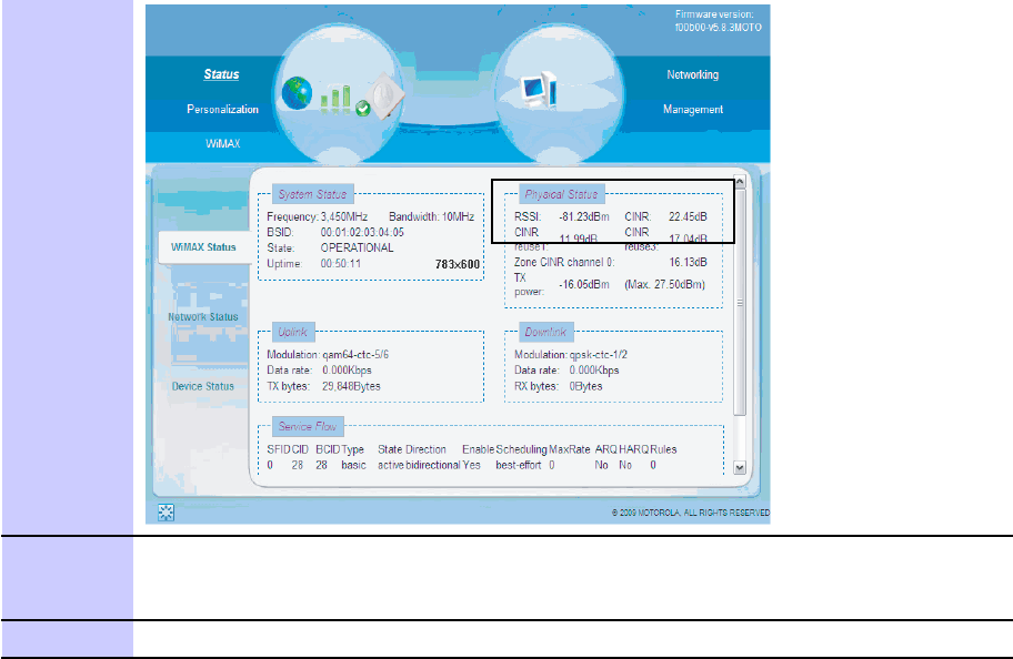
PMP320HDW2v1
5-11
Pr
e
limin
a
r
y
J
UL
2
0
1
0
PMP
320
Hardware
Installation
Aligning
the
CSM
for
best
signal
strength
Procedure
5-6
Adjusting
the
vertical
and
horizontal
tilt
of
the
CSM
for
level
of
service
connection
(Continued)
5
A
fter
finding
the
strongest
signal
from
the
service
provider
,
tighten
all
the
bolts
on
the
mounting
bracket
assembl
y
.
Once
the
screws
are
tightened,
the
CSM
will
no
longer
move
sideways,
nor
up
and
down.
6
Log
out
of
the
CSM
GUI
once
optimal
signal
strength
is
achieved.
A
fter
completing
the
alignment
and
mounting
of
the
CSM
on
the
outside
of
the
building,
proceed
with
the
installation
procedures
for
the
subscriber
Ethernet,
surge
suppression,
and
unit
Earth
Grounding
procedures.
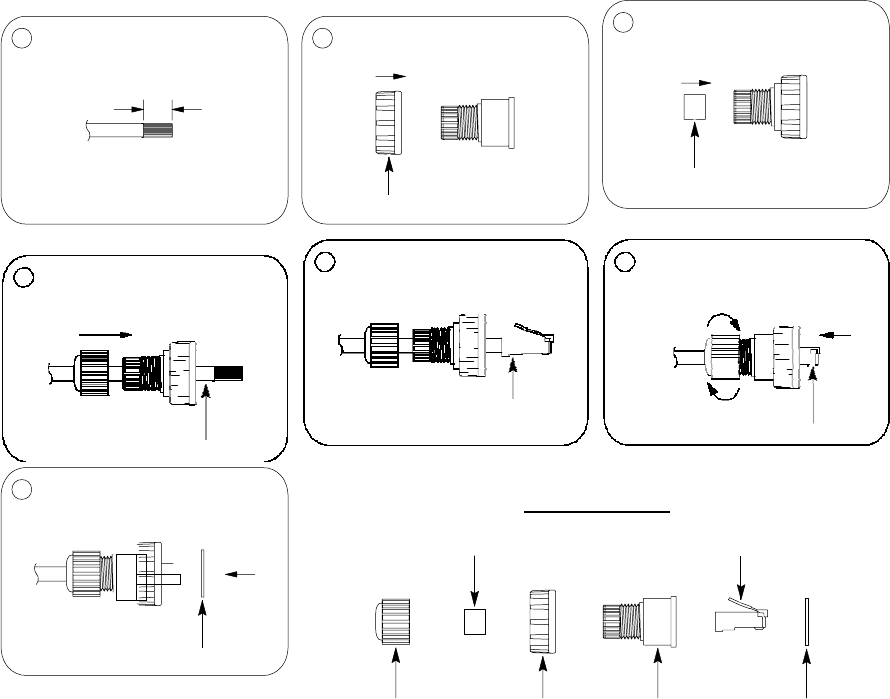
5-12
PMP320HDW2v1
Preliminary
JUL
2010
Connecting
the
CSM
to
the
Ethernet
cable,
Earth
Ground,
the
Surge
Suppressor
Chapter
5:
CSM
Hardware
Installation
Connecting
the
CSM
to
the
Ethernet
cable,
Earth
Ground,
the
Surge
Suppressor
■ ■ ■ ■ ■ ■ ■ ■ ■ ■ ■ ■ ■ ■ ■ ■ ■ ■ ■ ■ ■ ■ ■ ■ ■ ■ ■ ■ ■ ■ ■ ■ ■ ■ ■
■ ■ ■ ■ ■ ■ ■ ■ ■ ■ ■ ■ ■ ■ ■ ■ ■ ■ ■ ■ ■ ■ ■ ■ ■ ■
■
■
Ethernet
Cable
Assembly
Before
installing
the
CSM
Ethernet
cable,
ensure
that
the
Ethernet
cable
is
constructed
with
the
weather
protection
kit
that
is
contained
with
the
CSM
device.
Use
Figure
6
-
6
to
construct
the
weather
protection
housing
around
the
Ethernet
cable
and
RJ
-
45
plug.
This
weatherized
cable
connects
to
the
ENET
connector
of
the
CSM.
Figure
5-4
Ethernet
cable
weather
protection
assembly
1
Strip
cable
sheath.
2
Insert
the
screw
nut
into
the
housing.
3
Insert
the
seal
at
the
back
end
of
the
housing.
7.7
Recommended
wire
Gauge:
24AWG
Screw
Nut
Seal
4
Insert
the
cable
all
the
way
through.
Cable
5
Crimp
the
RJ45
plug.
Crimp
the
RJ45
plug
6
Insert
the
plug
into
the
housing.
Then
secure
the
sealing
nut
in
place.
Plug
7
Strick
the
gasket
on
the
front
end
of
the
housing.
Seal
Parts
Identification
RJ45
Plug
Gasket
Screw
Nut
Screw
Nut
Housing
Gasket
P
erform
the
following
procedure
to
connect
the
Ethernet/power
cable
to
the
CSM.

PMP320HDW2v1
5-13
Pr
e
limin
a
r
y
J
UL
2
0
1
0
PMP
320
Hardware
Installation
Ethernet
Cable
Assembly
Procedure
5-7
Connecting
the
Ethernet
cable
to
the
CSM
1
Cut
the
required
length
of
the
outdoor-rated
Category-5
Ethernet
cable
for
the
chosen
installation
site.
The
maximum
cable
length
is
100
m
(~330
ft).
2
T
erminate
the
cable
using
standard
RJ–45
connectors
using
the
procedure
as
shown
in
Figure
6-6
.
Use
dielectric
grease
(which
is
uniformly
non-conducting)
on
all
connections
and
in
all
RJ–45
Ethernet
connectors.
The
best
practice
is
to
use
enough
grease
to
fill
the
RJ–45
female
connector,
and
then
insert
the
RJ-45
male
connector
and
push
the
grease
further
into
the
unit
and
around
the
RJ–45
connector.
Excess
grease
can
be
wiped
over
the
connector
area
to
provide
some
resistance
to
water
ingress
around
the
connector.
3
W
rap
a
drip-loop
in
the
cable
at
any
point
where
the
cable
changes
direction.
4
Measure
the
cable
so
it
will
span
from
the
CSM
to
the
surge
suppressor
box.
5
F
asten
the
cable
to
the
building
according
to
local
building
codes.
NOTE
Cables
that
move
in
the
wind
can
be
damaged,
impart
vibrations
to
the
connected
device,
or
both.
A
t
installation
time,
prevent
these
problems
by
securing
all
cables
with
cable
ties,
cleats,
or
weather
resistant
tape.
The
cable
can
be
a
path
for
water
to
follow
to
enter
the
cable
connector
or
even
the
module.
Prevent
this
problem
by
including
and
securing
a
drip
loop
where
the
cable
enters
the
building.
Note: "Please select antenna cables suitable for outdoor communication system according to the
requirements of NFPA 70, National Electrical Code, 830.179."

5-14
PMP320HDW2v1
Preliminary
JUL
2010
Running
cables
through
the
wall
of
the
building
Chapter
5:
CSM
Hardware
Installation
Running
cables
through
the
wall
of
the
building
■ ■ ■ ■ ■ ■ ■ ■ ■ ■ ■ ■ ■ ■ ■ ■ ■ ■ ■ ■ ■ ■ ■ ■ ■ ■ ■ ■ ■ ■ ■ ■ ■ ■ ■
■ ■ ■ ■ ■ ■ ■ ■ ■ ■ ■ ■ ■ ■ ■ ■ ■ ■ ■ ■ ■ ■ ■ ■ ■ ■
■
■
The
power/Ethernet
cable
runs
from
inside
the
building
to
the
CSM.
The
following
procedure
describes
how
to
run
the
cables
through
the
wall
of
the
building.
CAUT
I
ON
Observe
caution
when
drilling
through
the
wall
of
the
building.
Ensure
that
there
are
no
power
lines,
gas
lines,
water
lines,
or
data
lines
in
the
wall
at
the
desired
location
where
the
drilling
takes
place.
Procedure
5-8
Running
cables
through
the
wall
of
the
building
1
CAUT
I
ON
Follow
local
building
codes
for
penetrating
buildings.
Observe
caution
when
drilling
through
the
wall
of
the
building.
Ensure
that
there
are
no
power
lines,
gas
lines,
water
lines,
or
data
lines
in
the
wall
at
the
desired
location.
Drill
a
3/4
inch.
(18
mm)
hole
through
the
wall
at
the
desired
location.
2
Draw
one
end
of
the
category
5e
cable
through
the
hole.
3
Route
the
category
5e
power/Ethernet
cable
from
the
surge
suppressor
to
the
location
where
the
power
supply
is
to
be
plugged
in.
4
A
fter
completing
the
installation,
use
a
grommet
for
the
hole
and
seal
the
hole
with
a
silicone
or
acrylic
caulking
material.

PMP320HDW2v1
5-15
Pr
e
limin
a
r
y
J
UL
2
0
1
0
PMP
320
Hardware
Installation
Installing
the
600SSD
Surge
Suppressor
Installing
the
600SSD
Surge
Suppressor
■ ■ ■ ■ ■ ■ ■ ■ ■ ■ ■ ■ ■ ■ ■ ■ ■ ■ ■ ■ ■ ■ ■ ■ ■ ■ ■ ■ ■ ■ ■ ■ ■ ■ ■
■ ■ ■ ■ ■ ■ ■ ■ ■ ■ ■ ■ ■ ■ ■ ■ ■ ■ ■ ■ ■ ■ ■ ■ ■ ■
■
■
Use
the
following
procedure
to
install
the
600S
SD
Surge
suppressor
.
CAUT
I
ON
Observe
caution
when
drilling
through
the
wall
of
the
building.
Ensure
that
there
are
no
power
lines,
gas
lines,
water
lines,
or
data
lines
in
the
wall
at
the
desired
location
where
the
drilling
takes
place.
Procedure
5-9
Installing
the
600SSD
Surge
Suppressor
1
W
ith
the
cable
openings
facing
downward,
install
the
600S
SD
surge
suppressor
above
the
site
where
the
hole
in
the
residence
has
been
drilled.
Use
two
screws
to
attach
the
unit
following
regulatory
building
guidelines.
2
Connect
the
surge
suppressor
to
Earth
Ground.
Refer
to
Connecting
the
CSM
to
the
Ethernet
cable,
Earth
Ground,
the
Surge
Suppressor
on
page
6-
13
.
Refer
to
Figure
6-7
.
3
P
ack
both
of
the
600S
SD
surge
suppressor
Ethernet
jacks
with
dielectric
grease.
4
Include
a
splicing
loop
in
the
Ethernet
cable
from
the
CSM
(extra
cable
to
allow
future
repositioning
or
reconnectorization)
and
position
and
secure
the
Ethernet
cable
with
UV
-resistant
wire
ties
or
other
locally-approved
fasteners
so
it
forms
a
drip
loop
(so
water
drips
off
the
cable
instead
of
following
the
cable
into
the
600S
SD
surge
suppressor).
5
Connect
the
Ethernet
connection
from
the
CSM
to
the
surge
suppressor
.
6
Build
another
Ethernet
cable
to
span
from
the
surge
suppressor
through
the
residence
wall
to
the
area
where
the
power
injector
will
be
placed
in
the
subscriber’s
residence.
7
Guide
the
Ethernet
cable
through
the
grommet
where
the
drilled
hole
was
made
into
the
residence.
8
Seal
the
cable
entry
point
into
the
building
using
accepted
industry
or
local
practices.
9
Connect
the
Ethernet
cable
to
the
Data
In
port
of
the
CSM
power
injector
.
Refer
to
Figure
6-8
.
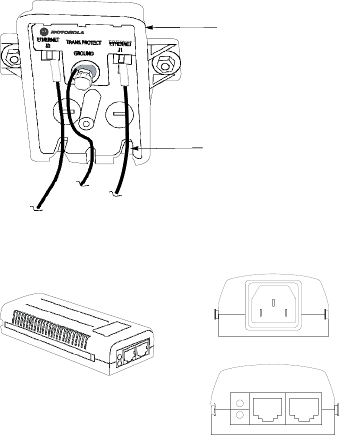
5-16
PMP320HDW2v1
Preliminary
JUL
2010
Connecting
the
ground
wire
Chapter
5:
CSM
Hardware
Installation
Figure
5-5
Cable
connections
from
the
surge
suppressor
to
the
CSM
power
injector
and
the
CSM
Surge
Suppressor
All
cables
must
exit
through
the
allocated
slots
Figure
5-6
CSM
320
power
injector
AC
POWER
DATA
&
POWER
DATA
OUT
IN
PORT
AC
Connecting
the
ground
wire
The
CSM
must
be
grounded
to
a
household
ground
point
or
to
a
grounding
rod
according
to
the
applicable
electrical
code.
Equipment
grounding
practices
vary
with
local
building
codes
and
established
practices
of
the
service
provider
.
F
ollowing
is
the
CSM
grounding
procedure
as
recommended
by
Motorola.
The
ground
wire
must
be
a
minimum
of
18
A
WG
,
with
14
A
WG
recommended
for
runs
up
to
45
m
(~150
ft)
and
10
A
WG
recommended
for
runs
over
45
m
(~150
ft)
.

PMP320HDW2v1
5-17
Pr
e
limin
a
r
y
J
UL
2
0
1
0
PMP
320
Hardware
Installation
Connecting
the
power
supply
and
the
Ethernet
cable
to
the
computer
NOTE
If
not
using
an
existing
approved
grounding
system,
install
a
grounding
system
(Protective
Earth)
according
to
applicable
regulations
or
codes.
Ground
the
CSM
using
one
of
the
following
methods:
•
If
grounding
a
CSM
installed
below
the
roof
line,
connect
the
CSM
to
the
ground
point
of
the
building
and
then
attach
all
wires
to
the
building
using
electrical
staples.
Use
drip
loops
as
required.
•
If
grounding
an
CSM
that
is
installed
above
the
roof
line,
then
perform
the
following:
Connect
the
ground
wire
from
the
CSM/surge
suppressor
to
the
ground
rod
in
the
ground
next
to
the
building.
Connect
the
ground
rod
to
the
household
ground
point
according
to
the
applicable
electrical
code.
A
ttach
all
wires
to
the
building
using
electrical
staples.
Use
drip
loops
as
required.
Use
the
following
procedure
to
ground
the
CSM
at
the
residence
premises.
Procedure
5-10
Grounding
the
CSM
1
W
rap
the
A
WG
10
(6mm2)
copper
ground
wire
around
the
ground
post
of
the
CSM.
2
Remove
the
cover
of
the
600S
SD
surge
suppressor
.
3
W
rap
the
A
WG
10
(6mm2)
copper
ground
wire
around
the
ground
post
of
the
600S
SD
.
4
Tighten
the
ground
post
locking
nut.
5
Ensure
the
pin
4
selector
in
the
600S
SD
is
set
to
the
factory
default
of
isolated,
not
grounded.
6
If
not
using
an
existing
approved
grounding
system,
install
a
grounding
system
(Protective
Earth)
according
to
applicable
regulations
or
codes.
7
Connect
the
ground
wire
from
the
CSM
and
the
600S
S
to
Earth
Ground.
Connecting
the
power
supply
and
the
Ethernet
cable
to
the
computer
P
erform
the
following
procedure
to
connect
the
power
supply
and
the
Ethernet
cables.

5-18
PMP320HDW2v1
Preliminary
JUL
2010
Connecting
the
power
supply
and
the
Ethernet
cable
to
the
computer
Chapter
5:
CSM
Hardware
Installation
Procedure
5-11
Connecting
the
power
supply
1
Plug
the
category
5e
cord
from
the
CSM/surge
suppressor
into
the
jack
labeled
AC
P
ower
on
the
CSM
P
ower
Injector
(if
this
connection
is
not
already
made).
2
Connect
the
protected
side
of
the
600S
SD
surge
suppressor
cable
to
the
Data
&
P
ower
Out
port
of
the
CSM
power
injector
.
3
Use
a
standard
category
5e
Ethernet
cable
to
connect
the
computer
to
the
jack
labeled
computer
on
the
power
suppl
y
.
NOTE
The
cable
to
the
CSM
provides
both
power
and
Ethernet
connection.
It
is
not
pin
or
voltage
compatible
with
IEE
std.802.3af
-2003
power
over
Ethernet.
4
The
power
cord
uses
standard
household
power.
Plug
the
power
cord
in
the
AC
power
source.
NOTE
The
AC
line
cord
is
not
provided
with
the
hardware.
Acquire
the
appropriate
power
line
cord
for
the
country
where
the
unit
is
installed.
Figure
6
-
8
illustrates
the
cable
connection
through
the
data
line
protector
and
into
the
power
supply
cord.

Chapter
6
Connectorized
CSM
Hardware
Installation
■ ■ ■ ■ ■ ■ ■ ■ ■ ■ ■ ■ ■ ■ ■ ■ ■ ■ ■ ■ ■ ■ ■ ■ ■ ■ ■ ■ ■ ■ ■ ■ ■ ■ ■
■ ■ ■ ■ ■ ■ ■ ■ ■ ■ ■ ■ ■ ■ ■ ■ ■ ■ ■ ■ ■ ■ ■ ■ ■ ■
■
■
■
■
This
chapter
provides
the
instructions
and
procedures
used
to:
•
connect
the
Connectorized
CSM
device
to
a
pole
or
wall
•
pre
-
power
up
alignment
for
level
of
service
connection
•
cable
the
unit
•
connect
the
antenna
cables
to
the
unit
•
ground
the
unit
•
add
surge
suppression
•
post
power
up
connection
•
IP
connectivity
alignment
correction
CAUT
I
ON
The
orientation
of
the
CSM
when
installed
is
important.
The
face
of
the
CSM
with the
Motorola
logo
must
be
pointing
in
the
direction
of
the
antenna
facing
outwards from
the
building.
The
Ethernet
connector
must
be
oriented
so
it
is
on
the
bottom
right
corner
of
the
Connectorized
CSM.
PMP320HDW2v1
6-1
JUL
2010
Preliminary
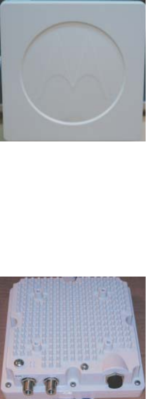
6-2
PMP320HDW2v1
Pr
e
limin
a
r
y
J
UL
2
0
1
0
Connecting
the
power
supply
and
the
Ethernet
cable
to
the
computer
Chapter
6:
Connectorized
CSM
Hardware
Installation
Figure
6-1
Connectorized
CSM
(CPE)
320
Identification
G1_CCSMfrtpanelview.eps
Figure
6-2
Connectorized
CSM
(CPE)
320
Rear
View
Connectors
G1_CCSM_rearviewconn.ext

PMP320HDW2v1
6-3
Preliminary
JUL
2010
PMP
320
Hardware
Installation
Before
you
begin
Before
you
begin
■ ■ ■ ■ ■ ■ ■ ■ ■ ■ ■ ■ ■ ■ ■ ■ ■ ■ ■ ■ ■ ■ ■ ■ ■ ■ ■ ■ ■ ■ ■ ■ ■ ■ ■
■ ■ ■ ■ ■ ■ ■ ■ ■ ■ ■ ■ ■ ■ ■ ■ ■ ■ ■ ■ ■ ■ ■ ■ ■ ■
■
■
This
section
describes
items
that
the
installer
or
subscriber
must
purchase
before
installing
the
CSM.
This
section
also
describes
items
that
must
be
available
and
points
to
consider
before
beginning
the
CSM
installation.
Additional
material
required
for
installation
The
additional
materials
required
for
installation
are
as
follows:
•
The
computer
of
the
subscriber
must
be
equipped
with
an
Ethernet
network
interface
card
(NIC).
NOTE
The
NIC
is
not
provided
with
the
CSM,
but
subscribers
can
purchase
a
NIC
at
most
computer
and
electronics
stores.
•
An
RJ–45
Ethernet
cable
to
connect
the
CSM
plug
-
in
power
supply
to
the
computer
.
•
Ground
wire
of
sufficient
length
to
run
between
the
CSM
and
the
home
ground
point.
NOTE
•
It
is
recommended
that
the
ground
wire
be
a
6
A
WG
,
solid
copper
wire.
•
It
is
recommended
that
if
a
ground
rod
is
used
it
should
be
an
8
ft
(2.5m)
copper
rod.
•
Most
buildings
have
an
existing
ground
rod
outside,
at
the
main
power
connection
site.
If
desired,
a
rod
can
be
installed
into
the
ground
outside
the
building
after
consulting
the
local
electrical
codes.
•
The
AC
line
cord
is
not
provided
with
the
hardware.
Acquire
the
appropriate
power
line
cord
for
the
country
where
the
unit
is
installed.
•
Lead
screw
anchors
if
the
CSM
is
mounted
on
a
brick
or
masonry
surface.
•
Outdoor
-
rated
category
5e
Ethernet
cable
to
connect
the
CSM
plug
-
in
power
supply
through
the
building
wall
to
the
CSM.
•
RJ–45
plug
connectors
and
the
tools
required
for
field
termination
of
the
category
5e
cable
•
Grommet
to
cover
a
3/4
inch.
(18
mm)
hole
•
Silicone
or
acrylic
caulking

6-4
PMP320HDW2v1
Pr
e
limin
a
r
y
J
UL
2
0
1
0
Pre-installation
planning
Chapter
6:
Connectorized
CSM
Hardware
Installation
Pre-installation
planning
While
on
the
ground,
find
an
appropriate
location
outside
the
building
to
mount
the
CSM.
NOTE
T
o
provide
Internet
service,
the
CSM
communicates
with
a
base
station
on
the
communications
tower
of
the
service
provider
.
Information
about
the
nearest
communications
tower
is
provided
by
the
service
provider
.
F
or
example,
if
the
tower
nearest
to
the
building
is
towards
the
north
of
the
building,
install
the
CSM
on
the
north
side
of
the
building.
A
fter
determining
the
optimal
side
of
the
building,
select
an
CSM
mounting
point
at
a
high
location
on
the
building
such
as
under
the
eaves.
Components
shipped
with
the
CSM
Locate
the
components
shipped
with
the
CSM
device.
The
parts
list
for
the
CSM
installation
consists
of
the
following
items:
Table
6-1
CSM
parts
list
Component
Quantity
CSM
320
device
1
Bracket
base
mounting
1
Bracket
Bottom
Mounting
1
Bracket
T
op
Mounting
1
Middle
mounting
bracket
1
M8
(50
mm)
hex
head
bolt
2
M8
(100
mm)
bolt
2
M8
split
washer
13
M8
washer
11
M8
nut
3
M5
(35
mm)
set
screw
2
M4
(16
mm)
bolt
4
M4
split
washer
4
M4
washer
4
Dsign
power
supply
1
ENET
cable
1
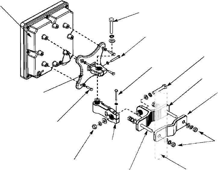
PMP320HDW2v1
6-5
Preliminary
JUL
2010
PMP
320
Hardware
Installation
Cabling
Overview
Figure
6-3
CSM
components
CSM320
M8
x
50
MM
Bolt
M8
Split
Washer
M8
Washer
M5
Set
Screw
35MM
M8
Split
Washer
M5
Set
Screw
35MM
M8
Split
Washer
M8
x
50
MM
Bolt
M8
Split
Washer
M8
Washer
Bracket
Base
Mounting
Bracket
Bottom
Mounting
Bracket
Top
Mounting
4X
M4
x
16MM
Bolt
4X
M4
Split
Washer
4X
M4
Washer
M8
Nut
M8
Split
Washer
M8
Washer
Middle
Mounting
bracket
2X
M8
x
100
MM
Bolt
2X
M8
Nut
4X
M8
Split
Washer
4X
M8
Washer
Mounting
Pole
(Reference)
Cabling
Overview
The
following
items
are
not
supplied
with
the
system:
•
Ground
wire
•
Grounding
rod
•
Outdoor
power/Ethernet
cable
•
Ethernet
cable
•
Computer
NIC
Figure
6
-
4
illustrates
the
routing
of
the
ground
wire,
the
category
5e
Ethernet
cable,
and
the
CSM
power/Ethernet
cable.
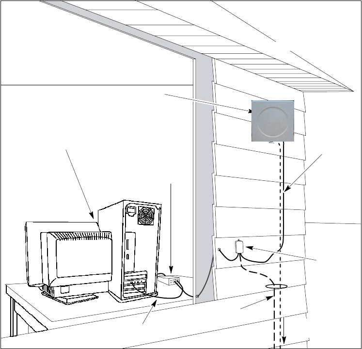
6-6
PMP320HDW2v1
Pr
e
limin
a
r
y
J
UL
2
0
1
0
Building’s
wall
Cabling
Overview
Chapter
6:
Connectorized
CSM
Hardware
Installation
Figure
6-4
CSM
mounted
to
a
wall
Building’s
Roof
CPE
Bracket
assembly
attached
to
building's
exterior
Connectorized
CSM
*antenna
not
shown
Subscriber’s
Computer
CPE
Power/Etherne
t
cable
Dsine
CPE
Bracket
assembly
attached
to
building's
exterior
Surge
Suppressor
Etherne
t
cable
(no
t
supplied)
Ground
wire
(no
t
supplied)
t
o
household
grounding
point

PMP320HDW2v1
6-7
Preliminary
JUL
2010
1
Using
a
laptop
and
a
temporary
power
source
connected
to
the
CSM
locate
the
optimal
site
for
the
CSM
to
be
installed.
Refer
to
the
PMP
320
Administration
and
Configuration
Guide
for
additional
information
on
accessing
the
CSM
GUI
and
status
settings.
htt // t l i l b db d t / t/lib /? i 1& t
2
Start
by
pointing
the
front
of
the
CSM
in
the
direction
that
is
most
likely
to
be
optimal.
3
Try
pointing
the
CSM
in
different
directions.
If
required,
perform
this
task
while
standing
in
the
upper
stories
or
on
the
roof
of
the
building.
A
t
each
elevation
and
in
each
direction
the
CSM
is
pointed.
4
A
fter
determining
the
place
where
the
best
signal
can
be
detected
using
the
CSM
GUI
screen
information,
choose
a
corresponding
CSM
installation
location
on
the
building.
NOTE
The
CSM
can
be
mounted
either
directly
on
the
building
or
on
a
pole.
PMP
320
Hardware
Installation
Installing
the
CSM
Installing
the
CSM
■ ■ ■ ■ ■ ■ ■ ■ ■ ■ ■ ■ ■ ■ ■ ■ ■ ■ ■ ■ ■ ■ ■ ■ ■ ■ ■ ■ ■ ■ ■ ■ ■ ■ ■
■ ■ ■ ■ ■ ■ ■ ■ ■ ■ ■ ■ ■ ■ ■ ■ ■ ■ ■ ■ ■ ■ ■ ■ ■ ■
■
■
This
section
describes
how
to
find
an
appropriate
installation
location
for
the
CSM,
and
how
to
install
the
CSM
on
the
building.
Selecting
a
location
for
the
CSM
Determine
the
optimum
installation
location
for
the
CSM
before
physically
mounting
the
CSM
to
the
building.
Most
often,
if
the
CSM
is
mounted
on
the
side
of
the
building
facing
the
base
station
of
the
service
provider
,
the
CSM
can
detect
adequate
signal
to
provide
high
-
speed
Internet
access.
However,
unless
there
is
an
obvious
line
of
sight
to
the
correct
base
station,
the
correct
orientation
of
the
CSM
is
often
not
apparent.
There
may
also
be
practical
reasons
why
the
CSM
cannot
be
mounted
on
the
side
of
the
building
that
faces
the
base
station.
Procedure
6-1
Selecting
an
installation
location
for
the
CSM
=8

6-8
PMP320HDW2v1
Pr
e
limin
a
r
y
J
UL
2
0
1
0
Installation
Overview
Chapter
6:
Connectorized
CSM
Hardware
Installation
Installation
Overview
■ ■ ■ ■ ■ ■ ■ ■ ■ ■ ■ ■ ■ ■ ■ ■ ■ ■ ■ ■ ■ ■ ■ ■ ■ ■ ■ ■ ■ ■ ■ ■ ■ ■ ■
■ ■ ■ ■ ■ ■ ■ ■ ■ ■ ■ ■ ■ ■ ■ ■ ■ ■ ■ ■ ■ ■ ■ ■ ■ ■
■
■
A
fter
finding
the
best
installation
location
on
the
building,
perform
the
following
procedure
to
install
the
CSM.
Procedure
6-2
Installing
the
Connectorized
CSM
1
Complete
the
mounting
bracket
assembly;
leave
the
screws
on
the
bracket
arm
slightly
loose.
If
the
screws
are
too
tight,
the
vertical
and
horizontal
tilt
of
the
CSM
cannot
be
adjusted
later
.
NOTE
If
fastening
the
CSM
to
a
pole,
add
the
pole
clamp
to
the
assembl
y
.
Otherwise,
set
the
pole
clamp
aside.
2
P
erform
one
of
the
following:
1.
If
attaching
the
CSM
to
the
side
of
a
building,
attach
the
CSM
to
the
building
using
the
wall
bracket
of
the
bracket
assembl
y
.
2.
Mount
the
CSM
to
a
pole
using
the
wall
bracket
and
pole
clamp
of
the
bracket
assembl
y
.
3
Adjust
the
vertical
and
horizontal
tilt
of
the
CSM
so
that
it
can
obtain
the
best
signal.
4
Fully
tighten
the
bracket
assembly
into
the
desired
position.
Completing
the
mounting
bracket
assembly
P
erform
the
following
procedure
to
complete
the
mounting
bracket
assembl
y
.
Refer
to
Figure
6
-
3
to
reference
the
brackets
and
the
assembly
of
the
brackets.
Procedure
6-3
Mounting
bracket
assembly
1
A
ttach
one
end
of
the
bracket
arm
to
the
arch
on
this
wall
bracket.
2
Insert
a
5/16×1½
hex
bolt
into
the
arch
of
the
wall
bracket
that
was
attached
to
the
CSM
in
step
1
.
Ensure
that
the
head
of
the
medium
hex
bolt
rests
inside
the
bolt
jam
of
the
arch.
3
Guide
the
rest
of
the
bolt
through
the
arch
of
the
wall
bracket.
4
Slide
a
tooth
lock
washer
on
the
end
of
the
hex
bolt.
5
Align
the
hole
on
one
tab
of
the
bracket
arm
with
the
end
of
the
bolt.
Continued

PMP320HDW2v1
6-9
Preliminary
JUL
2010
PMP
320
Hardware
Installation
Attaching
the
CSM
and
mounting
the
bracket
assembly
outside
the
building
Procedure
6-3
Mounting
bracket
assembly
(Continued)
6
Slide
the
bracket
arm
tab
onto
the
bolt,
and
then
place
a
flat
washer
over
the
end
of
the
bolt.
7
Tighten
the
end
of
the
bolt
with
a
hex
nut.
Leave
the
hex
nut
loose
enough
so
that
the
vertical
tilt
of
the
CSM
can
be
adjusted
later
.
8
A
ttach
the
other
end
of
the
bracket
arm
to
the
second
wall
bracket.
9
Insert
a
5/16×1½
hex
bolt
into
the
arch
of
the
second
wall
bracket.
This
bracket
is
attached
to
the
wall
or
clamped
to
a
pole.
NOTE
Ensure
that
the
head
of
the
hex
bolt
rests
inside
the
bolt
jam
found
on
the
arch.
When
the
assembly
is
complete,
ensure
that
the
bolt
jam
is
facing
the
ground.
10
Guide
the
rest
of
the
bolt
through
the
arch
of
the
wall
bracket.
11
Slide
a
tooth
lock
washer
at
the
end
of
the
hex
bolt.
12
Align
the
hole
on
the
tab
of
the
bracket
arm
with
the
end
of
the
bolt.
13
Slide
the
tab
of
the
bracket
arm
onto
the
bolt,
and
then
place
a
flat
washer
over
the
end
of
the
bolt.
14
Tighten
the
end
of
the
bolt
with
a
hex
nut.
Leave
the
hex
nut
loose
enough
so
that
the
horizontal
tilt
of
the
CSM
can
be
adjusted
later
.
15
If
fastening
the
CSM
to
a
pole,
loosely
attach
the
clamp
to
wall
bracket
2.
P
erform
the
steps
listed
in
the
section
F
astening
the
CSM
and
mounting
the
bracket
assembly
to
a
pole.
Attaching
the
CSM
and
mounting
the
bracket
assembly
outside
the
building
W
AR
NING
Maintain
a
safe
distance
from
RF
exposure
at
least
120
cm
when
installing the
CSM
to
the
subscriber
building.
Maintain
safe
distances
from
power
lines.
P
erform
the
following
procedure
to
attach
the
CSM
to
the
outside
of
the
building.

6-10
PMP320HDW2v1
Pr
e
limin
a
r
y
J
UL
2
0
1
0
Fastening
the
CSM
and
mounting
the
bracket
assembly
to
a
pole
Chapter
6:
Connectorized
CSM
Hardware
Installation
Procedure
6-4
Attaching
the
CSM
and
mounting
the
bracket
assembly
outside
the
building
1
Where
possible,
install
the
CSM
on
the
side
of
the
building
that
has
the
greatest
exposure
to
the
communications
tower
of
the
service
provider
.
The
service
provider
can
provide
information
about
tower
locations
that
can
provide
the
CSM
with
the
greatest
signal
exposure.
2
Drill
holes
into
the
exterior
wall
of
the
building
where
the
CSM
must
be
hung.
•
Drill
the
two
top
holes
2.5
inches
apart.
Drill
the
bottom
holes
2.5
inches
below
the
top
holes.
•
If
possible,
drill
one
upper
hole
and
its
corresponding
lower
hole
into
a
stud.
Do
not
allow
the
CSM
to
be
supported
by
the
siding
of
the
building.
•
If
installing
the
CSM
on
a
brick
or
masonry
surface,
use
appropriate
anchors.
CAUT
I
ON
Observe
caution
when
drilling
through
the
wall
of
the
building.
Ensure
that
there
are
no
power
lines,
gas
lines,
water
lines,
or
data
lines
in
the
wall
at
the
desired
location
where
the
drilling
takes
place.
3
A
fter
the
holes
are
drilled
into
the
building,
drive
the
screws
through
the
holes
on
the
wall
bracket
and
into
the
building.
While
attaching
the
bracket
assembly
to
the
wall,
ensure
that
the
bottom
of
the
CSM
is
pointing
towards
the
ground.
The
bottom
of
the
CSM
is
the
side
with
the
five
lights
and
the
grounding
lug.
The
CSM
must
be
installed
verticall
y
.
Fastening
the
CSM
and
mounting
the
bracket
assembly
to
a
pole
If
fastening
the
CSM
to
a
pole,
add
the
pole
clamp
to
the
assembl
y
.
P
erform
the
following
procedure
to
fasten
the
CSM
to
a
pole.
Procedure
6-5
Fastening
the
CSM
and
mounting
the
bracket
assembly
to
a
pole
1
Insert
the
following
through
the
holes
on
the
clamp:
•
Large
hex
bolt
•
Large
split
washer
•
Large
washer
2
Place
the
clamp
around
the
pole.
3
Align
the
screw
assembly
with
the
center
holes
on
the
wall
bracket.
4
Tighten
the
clamp
so
that
the
bracket
assembly
and
the
attached
CSM
are
tight
on
the
pole.
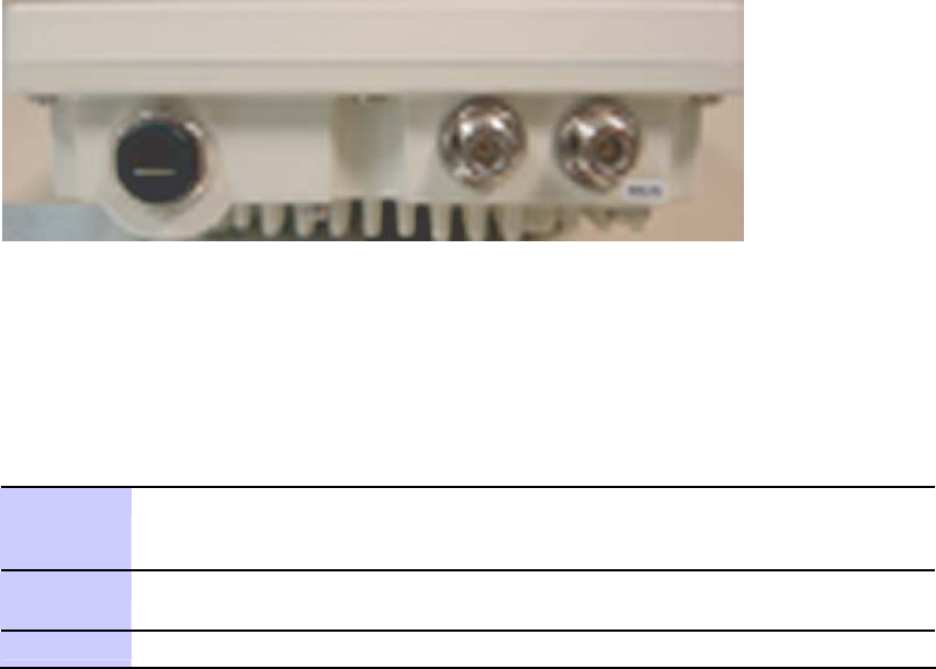
PMP320HDW2v1
6-11
Preliminary
JUL
2010
PMP
320
Hardware
Installation
Connecting
the
Antenna
Cables
to
the
Unit
Connecting
the
Antenna
Cables
to
the
Unit
■ ■ ■ ■ ■ ■ ■ ■ ■ ■ ■ ■ ■ ■ ■ ■ ■ ■ ■ ■ ■ ■ ■ ■ ■ ■ ■ ■ ■ ■ ■ ■ ■ ■ ■
■ ■ ■ ■ ■ ■ ■ ■ ■ ■ ■ ■ ■ ■ ■ ■ ■ ■ ■ ■ ■ ■ ■ ■ ■ ■
■
■
Use
the
following
procedure
to
connect
the
antenna
cables
to
the
unit.
Depending
upon
the
type
of
antenna
used,
either
two
omni
antennas,
or
one
diagonal
polarized
antenna,
the
connectors
from
the
installed
antennas
must
be
connected
to
the
Connectorized
CSM
unit
N
-
type
connectors.
Ensure
that
the
cable
length
between
the
CSM
and
the
antenna
connectors
is
18
inches
(1
ft
and
6
in).
Refer
to
the
Chapter
titled
Installing
Antennas
for
additional
information
regarding
antenna
installation
procedures.
Figure
6-5
Connectorized
CSM
antenna
cable
connector
location
G1_Ccsman
t
ennaconnid
.
eps
Procedure
6-6
Connecting
the
Antenna
Cables
to
the
Connectorized
CSM
when
using
an
Omni
Antenna
1
V
erify
that
the
length
between
the
CSM
and
the
Omni
antennas
is
18
inches
apart
(1
ft
and
6
in).
Refer
to
Figure
6-5
for
cable
connection
location
on
the
CSM.
2
Using
a
50
ohm
low
loss
cable
with
an
N-type
connector,
connect
the
end
of
the
cable
from
the
Omni
antenna
connector
to
the
CSM
N-type
connector.
3
Repeat
step
1
for
the
second
Omni
antenna.

6-12
PMP320HDW2v1
Pr
e
limin
a
r
y
J
UL
2
0
1
0
Connecting
the
Antenna
Cables
to
the
Unit
Chapter
6:
Connectorized
CSM
Hardware
Installation
Procedure
6-7
Connecting
the
Antenna
Cables
to
the
Connectorized
CSM
when
using
an
Diagonal
Polarized
Antenna
1
Using
a
50
ohm
low
loss
cable
with
an
N-type
connector,
connect
the
N-type
connector
to
the
V
-polarity
connector
of
the
antenna
to
the
CSM
N-type
connector.
Refer
to
Figure
6-5
for
cable
connection
location
on
the
CSM.
2
Using
the
other
50
ohm
cable,
connect
the
N-type
connector
to
the
H-polarity
connector
of
the
antenna
to
the
CSM
N-type
connector.
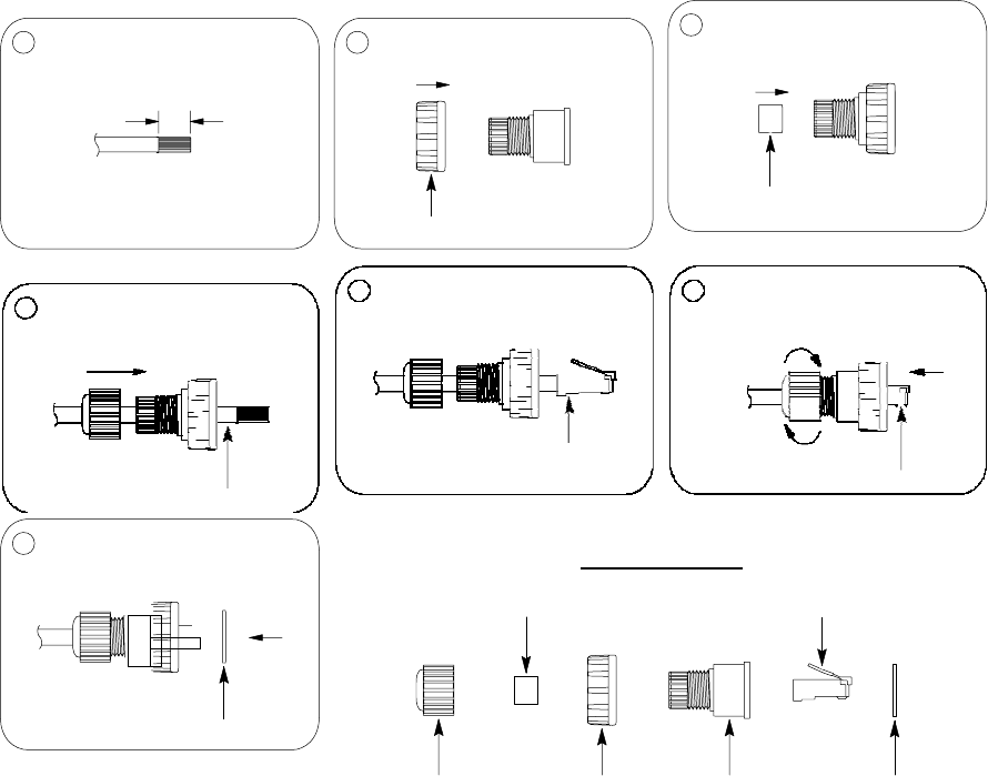
PMP320HDW2v1
6-13
Preliminary
JUL
2010
PMP
320
Hardware
Installation
Connecting
the
CSM
to
the
Ethernet
cable,
Earth
Ground,
the
Surge
Suppressor
Connecting
the
CSM
to
the
Ethernet
cable,
Earth
Ground,
the
Surge
Suppressor
■ ■ ■ ■ ■ ■ ■ ■ ■ ■ ■ ■ ■ ■ ■ ■ ■ ■ ■ ■ ■ ■ ■ ■ ■ ■ ■ ■ ■ ■ ■ ■ ■ ■ ■
■ ■ ■ ■ ■ ■ ■ ■ ■ ■ ■ ■ ■ ■ ■ ■ ■ ■ ■ ■ ■ ■ ■ ■ ■ ■
■
■
Ethernet
Cable
Assembly
Before
installing
the
CSM
Ethernet
cable,
ensure
that
the
Ethernet
cable
is
constructed
with
the
weather
protection
kit
that
is
contained
with
the
CSM
device.
Use
Figure
6
-
6
to
construct
the
weather
protection
housing
around
the
Ethernet
cable
and
RJ
-
45
plug.
This
weatherized
cable
connects
to
the
ENET
connector
of
the
CSM.
Figure
6-6
Ethernet
cable
weather
protection
assembly
1
Strip
cable
sheath.
2
Insert
the
screw
nut
into
the
housing.
3
Insert
the
seal
at
the
back
end
of
the
housing.
7.7
Recommended
wire
Gauge:
24AWG
Screw
Nut
Seal
4
Insert
the
cable
all
the
way
through.
Cable
5
Crimp
the
RJ45
plug.
Crimp
the
RJ45
plug
6
Insert
the
plug
into
the
housing.
Then
secure
the
sealing
nut
in
place.
Plug
7
Strick
the
gasket
on
the
front
end
of
the
housing.
Seal
Parts
Identification
RJ45
Plug
Gasket
Screw
Nut
Screw
Nut
Housing
Gasket
P
erform
the
following
procedure
to
connect
the
Ethernet/power
cable
to
the
CSM.

6-14
PMP320HDW2v1
Pr
e
limin
a
r
y
J
UL
2
0
1
0
Ethernet
Cable
Assembly
Chapter
6:
Connectorized
CSM
Hardware
Installation
Procedure
6-8
Connecting
the
Ethernet
cable
to
the
CSM
1
Cut
the
required
length
of
the
outdoor-rated
Category-5
Ethernet
cable
for
the
chosen
installation
site.
The
maximum
cable
length
is
100
m
(~330
ft).
2
T
erminate
the
cable
using
standard
RJ–45
connectors
using
the
procedure
as
shown
in
Figure
6-6
.
Use
dielectric
grease
(which
is
uniformly
non-conducting)
on
all
connections
and
in
all
RJ–45
Ethernet
connectors.
The
best
practice
is
to
use
enough
grease
to
fill
the
RJ–45
female
connector,
and
then
insert
the
RJ-45
male
connector
and
push
the
grease
further
into
the
unit
and
around
the
RJ–45
connector.
Excess
grease
can
be
wiped
over
the
connector
area
to
provide
some
resistance
to
water
ingress
around
the
connector.
3
W
rap
a
drip-loop
in
the
cable
at
any
point
where
the
cable
changes
direction.
4
Measure
the
cable
so
it
will
span
from
the
CSM
to
the
surge
suppressor
box.
5
F
asten
the
cable
to
the
building
according
to
local
building
codes.
NOTE
Cables
that
move
in
the
wind
can
be
damaged,
impart
vibrations
to
the
connected
device,
or
both.
A
t
installation
time,
prevent
these
problems
by
securing
all
cables
with
cable
ties,
cleats,
or
weather
resistant
tape.
The
cable
can
be
a
path
for
water
to
follow
to
enter
the
cable
connector
or
even
the
module.
Prevent
this
problem
by
including
and
securing
a
drip
loop
where
the
cable
enters
the
building.

PMP320HDW2v1
6-15
Preliminary
JUL
2010
PMP
320
Hardware
Installation
Running
cables
through
the
wall
of
the
building
Running
cables
through
the
wall
of
the
building
■ ■ ■ ■ ■ ■ ■ ■ ■ ■ ■ ■ ■ ■ ■ ■ ■ ■ ■ ■ ■ ■ ■ ■ ■ ■ ■ ■ ■ ■ ■ ■ ■ ■ ■
■ ■ ■ ■ ■ ■ ■ ■ ■ ■ ■ ■ ■ ■ ■ ■ ■ ■ ■ ■ ■ ■ ■ ■ ■ ■
■
■
The
power/Ethernet
cable
runs
from
inside
the
building
to
the
CSM.
The
following
procedure
describes
how
to
run
the
cables
through
the
wall
of
the
building.
CAUT
I
ON
Observe
caution
when
drilling
through
the
wall
of
the
building.
Ensure
that
there
are
no
power
lines,
gas
lines,
water
lines,
or
data
lines
in
the
wall
at
the
desired
location
where
the
drilling
takes
place.
Procedure
6-9
Running
cables
through
the
wall
of
the
building
1
CAUT
I
ON
Follow
local
building
codes
for
penetrating
buildings.
Observe
caution
when
drilling
through
the
wall
of
the
building.
Ensure
that
there
are
no
power
lines,
gas
lines,
water
lines,
or
data
lines
in
the
wall
at
the
desired
location.
Drill
a
3/4
inch.
(18
mm)
hole
through
the
wall
at
the
desired
location.
2
Draw
one
end
of
the
category
5e
cable
through
the
hole.
3
Route
the
category
5e
power/Ethernet
cable
from
the
surge
suppressor
to
the
location
where
the
power
supply
is
to
be
plugged
in.
4
A
fter
completing
the
installation,
use
a
grommet
for
the
hole
and
seal
the
hole
with
a
silicone
or
acrylic
caulking
material.

6-16
PMP320HDW2v1
Pr
e
limin
a
r
y
J
UL
2
0
1
0
Installing
the
600SSD
Surge
Suppressor
Chapter
6:
Connectorized
CSM
Hardware
Installation
Installing
the
600SSD
Surge
Suppressor
■ ■ ■ ■ ■ ■ ■ ■ ■ ■ ■ ■ ■ ■ ■ ■ ■ ■ ■ ■ ■ ■ ■ ■ ■ ■ ■ ■ ■ ■ ■ ■ ■ ■ ■
■ ■ ■ ■ ■ ■ ■ ■ ■ ■ ■ ■ ■ ■ ■ ■ ■ ■ ■ ■ ■ ■ ■ ■ ■ ■
■
■
Use
the
following
procedure
to
install
the
600S
SD
Surge
suppressor
.
CAUT
I
ON
Observe
caution
when
drilling
through
the
wall
of
the
building.
Ensure
that
there
are
no
power
lines,
gas
lines,
water
lines,
or
data
lines
in
the
wall
at
the
desired
location
where
the
drilling
takes
place.
Procedure
6-10
Installing
the
600SSD
Surge
Suppressor
1
W
ith
the
cable
openings
facing
downward,
install
the
600S
SD
surge
suppressor
above
the
site
where
the
hole
in
the
residence
has
been
drilled.
Use
two
screws
to
attach
the
unit
following
regulatory
building
guidelines.
2
Connect
the
surge
suppressor
to
Earth
Ground.
Refer
to
Connecting
the
CSM
to
the
Ethernet
cable,
Earth
Ground,
the
Surge
Suppressor
on
page
6-
13
.
Refer
to
Figure
6-7
.
3
P
ack
both
of
the
600S
SD
surge
suppressor
Ethernet
jacks
with
dielectric
grease.
4
Include
a
splicing
loop
in
the
Ethernet
cable
from
the
CSM
(extra
cable
to
allow
future
repositioning
or
reconnectorization)
and
position
and
secure
the
Ethernet
cable
with
UV
-resistant
wire
ties
or
other
locally-approved
fasteners
so
it
forms
a
drip
loop
(so
water
drips
off
the
cable
instead
of
following
the
cable
into
the
600S
SD
surge
suppressor).
5
Connect
the
Ethernet
connection
from
the
CSM
to
the
surge
suppressor
.
6
Build
another
Ethernet
cable
to
span
from
the
surge
suppressor
through
the
residence
wall
to
the
area
where
the
power
injector
will
be
placed
in
the
subscriber’s
residence.
7
Guide
the
Ethernet
cable
through
the
grommet
where
the
drilled
hole
was
made
into
the
residence.
8
Seal
the
cable
entry
point
into
the
building
using
accepted
industry
or
local
practices.
9
Connect
the
Ethernet
cable
to
the
Data
In
port
of
the
CSM
power
injector
.
Refer
to
Figure
6-8
.
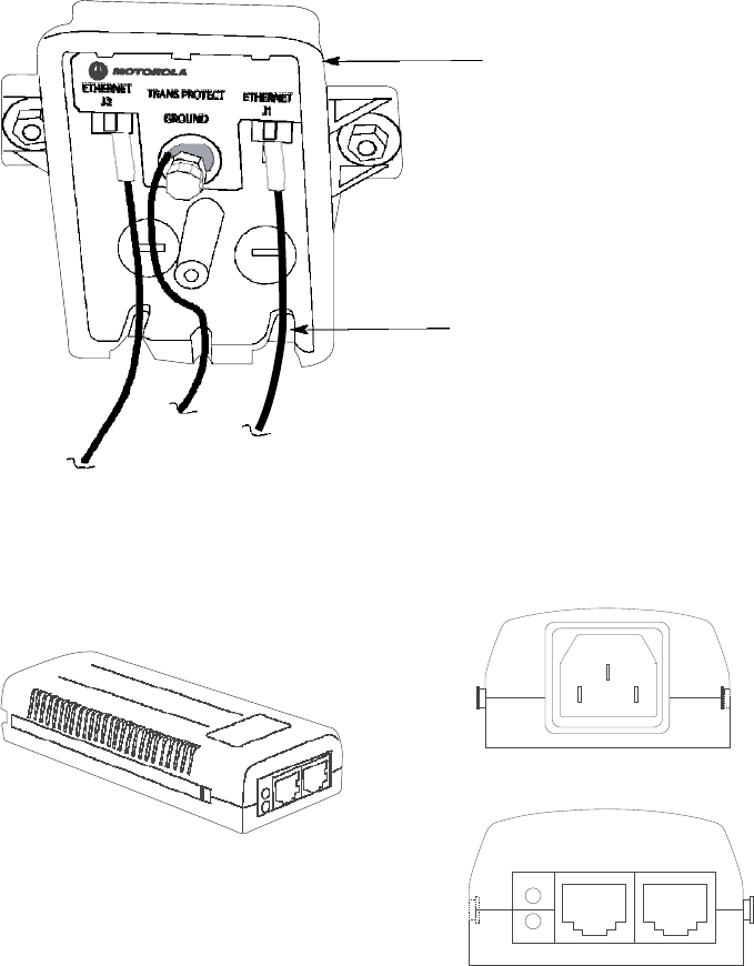
PMP320HDW2v1
6-17
Preliminary
JUL
2010
PMP
320
Hardware
Installation
Connecting
the
ground
wire
Figure
6-7
Cable
connections
from
the
surge
suppressor
to
the
CSM
power
injector
and
the
CSM
Surge
Suppressor
All
cables
must
exit
through
the
allocated
slots
Figure
6-8
CSM
320
power
injector
AC
POWER
DATA
&
POWER
DATA
OUT
IN
PORT
AC
Connecting
the
ground
wire
The
CSM
must
be
grounded
to
a
household
ground
point
or
to
a
grounding
rod
according
to
the
applicable
electrical
code.
Equipment
grounding
practices
vary
with
local
building
codes
and
established
practices
of
the
service
provider
.
F
ollowing
is
the
CSM
grounding
procedure
as
recommended
by
Motorola.
The
ground
wire
must
be
a
minimum
of
18
A
WG
,
with
14
A
WG
recommended
for
runs
up
to
45
m
(~150
ft)
and
10
A
WG
recommended
for
runs
over
45
m
(~150
ft)
.

6-18
PMP320HDW2v1
Pr
e
limin
a
r
y
J
UL
2
0
1
0
Connecting
the
power
supply
and
the
Ethernet
cable
to
the
computer
Chapter
6:
Connectorized
CSM
Hardware
Installation
NOTE
If
not
using
an
existing
approved
grounding
system,
install
a
grounding
system
(Protective
Earth)
according
to
applicable
regulations
or
codes.
Ground
the
CSM
using
one
of
the
following
methods:
•
If
grounding
a
CSM
installed
below
the
roof
line,
connect
the
CSM
to
the
ground
point
of
the
building
and
then
attach
all
wires
to
the
building
using
electrical
staples.
Use
drip
loops
as
required.
•
If
grounding
an
CSM
that
is
installed
above
the
roof
line,
then
perform
the
following:
Connect
the
ground
wire
from
the
CSM/surge
suppressor
to
the
ground
rod
in
the
ground
next
to
the
building.
Connect
the
ground
rod
to
the
household
ground
point
according
to
the
applicable
electrical
code.
A
ttach
all
wires
to
the
building
using
electrical
staples.
Use
drip
loops
as
required.
Use
the
following
procedure
to
ground
the
CSM
at
the
residence
premises.
Procedure
6-11
Grounding
the
CSM
1
W
rap
the
A
WG
10
(6mm2)
copper
ground
wire
around
the
ground
post
of
the
CSM.
2
Remove
the
cover
of
the
600S
SD
surge
suppressor
.
3
W
rap
the
A
WG
10
(6mm2)
copper
ground
wire
around
the
ground
post
of
the
600S
SD
.
4
Tighten
the
ground
post
locking
nut.
5
Ensure
the
pin
4
selector
in
the
600S
SD
is
set
to
the
factory
default
of
isolated,
not
grounded.
6
If
not
using
an
existing
approved
grounding
system,
install
a
grounding
system
(Protective
Earth)
according
to
applicable
regulations
or
codes.
7
Connect
the
ground
wire
from
the
CSM
and
the
600S
S
to
Earth
Ground.
Connecting
the
power
supply
and
the
Ethernet
cable
to
the
computer
P
erform
the
following
procedure
to
connect
the
power
supply
and
the
Ethernet
cables.

JUL
2010
Preliminary
PMP
320
Hardware
Installation
Connecting
the
power
supply
and
the
Ethernet
cable
to
the
computer
Procedure
6-12
Connecting
the
power
supply
1
Plug
the
category
5e
cord
from
the
CSM/surge
suppressor
into
the
jack
labeled
AC
P
ower
on
the
CSM
P
ower
Injector
(if
this
connection
is
not
already
made).
2
Connect
the
protected
side
of
the
600S
SD
surge
suppressor
cable
to
the
Data
&
P
ower
Out
port
of
the
CSM
power
injector
.
3
Use
a
standard
category
5e
Ethernet
cable
to
connect
the
computer
to
the
jack
labeled
computer
on
the
power
suppl
y
.
NOTE
The
cable
to
the
CSM
provides
both
power
and
Ethernet
connection.
It
is
not
pin
or
voltage
compatible
with
IEE
std.802.3af
-2003
power
over
Ethernet.
4
The
power
cord
uses
standard
household
power.
Plug
the
power
cord
in
the
AC
power
source.
NOTE
The
AC
line
cord
is
not
provided
with
the
hardware.
Acquire
the
appropriate
power
line
cord
for
the
country
where
the
unit
is
installed.
Figure
6
-
8
illustrates
the
cable
connection
through
the
data
line
protector
and
into
the
power
supply
cord.
PMP320HDW2v1
6-19
Preliminary
JUL
2010
Connecting
the
power
supply
and
the
Ethernet
cable
to
the
computer
Chapter
6:
Connectorized
CSM
Hardware
Installation
6-20
PMP320HDW2v1

JUL
2010
Preliminary
Chapter
7
Connectorized
CSM
Antenna
Installation
Instructions
■ ■ ■ ■ ■ ■ ■ ■ ■ ■ ■ ■ ■ ■ ■ ■ ■ ■ ■ ■ ■ ■ ■ ■ ■ ■ ■ ■ ■ ■ ■ ■ ■ ■ ■
■ ■ ■ ■ ■ ■ ■ ■ ■ ■ ■ ■ ■ ■ ■ ■ ■ ■ ■ ■ ■ ■ ■ ■ ■ ■
■
■
■
■
PMP320HDW2v1
7-1
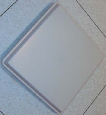
Preliminary
JUL
2010
Antenna
Types
used
with
the
Connectorized
CSM
Chapter
7:
Connectorized
CSM
Antenna
Installation
Instructions
Antenna
Types
used
with
the
Connectorized
CSM
■ ■ ■ ■ ■ ■ ■ ■ ■ ■ ■ ■ ■ ■ ■ ■ ■ ■ ■ ■ ■ ■ ■ ■ ■ ■ ■ ■ ■ ■ ■ ■ ■ ■ ■
■ ■ ■ ■ ■ ■ ■ ■ ■ ■ ■ ■ ■ ■ ■ ■ ■ ■ ■ ■ ■ ■ ■ ■ ■ ■
■
■
There
are
two
antenna
types
that
have
been
tested
with
the
Connectorized
CSM
PMP
320
product.
The
antennas
that
have
been
tested
are
as
follows:
•
3.3
-
3.8
GHz
Dual
P
olarization/
Dual
Slant
Subscriber
Antenna
•
3.3
-
3.8
GHz
Omni
Directional
Base
Station
Antenna
This
section
provides
installation
procedures
for
both
types
of
antennas.
Dual
Polarization/Dual
Slant
Subscriber
Antenna
The
Dual
P
olarization
Dual
Slant
antenna
features
dual
slant
when
it
is
mounted
diagonall
y
.
It
also
offers:
•
stable
performance
with
22
dBi
of
gain
•
compact
size
allowing
easy
blending
in
any
environment
•
mount
hardware
that
allows
for
quick
and
easy
45
degree
turn
installation
•
UV
protected
radome
suitable
for
harsh
environments
Figure
7-1
Dual
Polarization/Dual
Slant
Subscriber
Antenna
G1diagan
tt
ccsml
.
eps
7-2
PMP320HDW2v1

PMP320HDW2v1
7-23
Preliminary
JUL
2010
PMP
320
Hardware
Installation
Dual
Polarization/Dual
Slant
Subscriber
Antenna
Specifications
The
Dual
P
olarized
/
Dual
Slant
Subscriber
Antenna
is
produced
with
the
following
specifications:
Table
7-1
Dual
Polarized
/
Dual
Slant
Subscriber
Antenna
Electrical
Specifications
Specification
Value
Frequency
range
3.3
–
3.8
GHz
GAIN
:
H-P
ort
&
V
-P
ort
22dBi
VSWR,
max.
1.7
:
1
P
olarization
Dual
P
ole
Linear
,
V
ertical
&
Horizontal
Dual
Slant
(optional)
±
45°
3
dB
Beam-W
idth,
H-Plane,
typ.
12°
3
dB
Beam-W
idth,
E-Plane,
typ.
12°
Cross
P
olarization,
max
ETSI
TS3
Front
to
Back
R
atio,
max.
ETSI
TS3
P
ort
to
P
ort
Isolation,
typ.
-35
dB
Input
power,
max
10
W
att
Input
Impedance
50
Ohm
Lightning
Protection
DC
Grounded
Table
7-2
Dual
Polarized
/
Dual
Slant
Subscriber
Antenna
Mechanical
Specifications
Specification
Value
Dimensions
(HxWxD)
370
x
370
x
40
mm
(14.5"
x14.5"
x1.6")
W
eight
2.1
kg
Connector
2x
SMA,
F
emale
or
2x
N-
Type,
F
emale
Back
Plane
Aluminum;
protected
through
chemical
passivation
R
adome
Plastic
UV
Protected
Mount
MN
T
-22
Table
7-3
Dual
Polarized
/
Dual
Slant
Subscriber
Antenna
Environmental
Specifications
Specification
Value
Operating
T
emperature
R
ange
-
55°C
to
+
65°C
V
ibration
According
to
IEC
60721-3-4
W
ind
Load
200
km/h
(survival)
Flammability
UL94
Continued

7-24
PMP320HDW2v1
Pr
e
limin
a
r
y
J
UL
2
0
1
0
Dual
Polarization/Dual
Slant
Subscriber
Antenna
Chapter
7:
Connectorized
CSM
Antenna
Installation
Instructions
Table
7-3
Dual
Polarized
/
Dual
Slant
Subscriber
Antenna
Environmental
Specifications
(Continued)
Specification
Value
W
ater
Proofing
IP-67
Humidity
ETS
300
019-1-4,
EN
302
085
(annex
A.1.1
Salt
F
og
According
to
IEC
68-2-11
Ice
and
Snow
25mm
radial
(survival)
Service
Life
>10
years
The
Standard
Compliance
of
the
Dual
P
olarized
/
Dual
Slant
Subscriber
Antenna
is
ETSI
TS3.
Parts
List
Table
7-4
Dual
Polarized
/
Dual
Slant
Subscriber
Antenna
Parts
List
Quantity
Description
1
P
ole
1
inch
to
4
inches
(not
supplied)
1
MN
T
-22–1
1
MN
T
-22–2
1
MN
T
-22–4
1
MN
T
-22–3
4
5/16
Helical
spring
lock
washers
4
5/16
plain
washer
2
5/16–18
x
1.25
inch
Hex
cap
screws
2
5/16–18
x
5
inch
hex
cap
screws
4
1/4
plain
washer
4
1/4
helical
spring
lock
washer
4
1/4–20
hex
nut
2
5/16–18
hex
nut
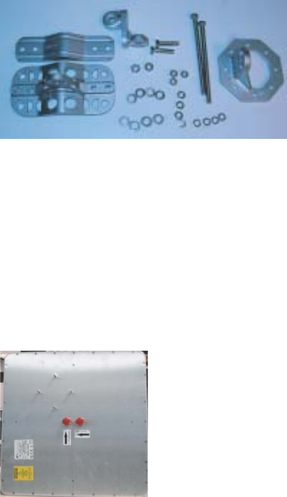
PMP320HDW2v1
7-25
Preliminary
JUL
2010
PMP
320
Hardware
Installation
Dual
Polarization/Dual
Slant
Subscriber
Antenna
Figure
7-2
Mounting
Bracket
Parts
Identification
G1_antassemblyparts.eps
Tools
The
following
tools
are
needed
for
the
antenna
mounting
bracket
assembly:
•
T
orque
driver
–
30
in
-
lbs
Antenna
Mounting
Instructions
Use
the
following
procedure
to
mount
the
Dual
P
olarized
/
Dual
Slant
Subscriber
Antenna.
Figure
7-3
Dual
Polarized
/
Dual
Slant
Subscriber
Antenna
Rear
View
for
Mounting
Assembly
G1_an
t
assemblyrearview
.
eps

7-26
PMP320HDW2v1
Pr
e
limin
a
r
y
J
UL
2
0
1
0
Omni
Directional
Base
Station
Antenna
Chapter
7:
Connectorized
CSM
Antenna
Installation
Instructions
Procedure
7-1
Mounting
the
Dual
Polarized
/
Dual
Slant
Subscriber
Antenna
to
a
pole
1
Place
part
number
MN
T
-22–1
(antenna
mounting
plate)
on
the
antenna
and
align
with
the
screw
holes.
2
Connect
part
number
MN
T
-22–1
(middle
mounting
bracket)
to
the
antenna
mounting
plate
with
four
1/4
inch
spring
washers,
four
1/4
inch
flat
washers,
and
four
1/4–20
hex
nuts.
Tighten
the
hex
nuts
with
a
torque
driver
to
30
in-lbs.
3
A
ttach
part
number
MN
T
-22–2
to
the
antenna
mounting
plate
assembly
using
a
5/16
inch
helical
spring
lock
washer
,
a
5/16
inch
plain
washer
,
a
5/16–18
x
1.25
inch
hex
cap
scre
w
,
and
a
5/16–18
hex
nut.
Leave
the
assembly
loosely
tightened.
Do
not
torque
the
nuts
at
this
step.
4
A
ttach
part
number
MN
T
-22-3
(bottom
pole
mounting
bracket)
to
the
assembly
from
step
3.
Use
a
5/16
inch
helical
spring
lock
washer
,
a
5/16
inch
plain
washer
,
a
5/16–18
x
1.25
inch
hex
cap
scre
w
,
and
a
5/16–18
hex
nut.
Leave
the
assembly
loosely
tightened.
Do
not
torque
the
nuts
at
this
step.
5
Locate
the
area
of
the
pole
to
mount
the
antenna,
and
place
the
bottom
pole
mounting
bracket
with
the
rest
of
the
assembly
on
the
pole.
6
A
ttach
the
top
pole
bracket
part
number
MN
T
-22–4
to
the
bottom
pole
mounting
bracket
and
assembly
using
two
5/16
helical
spring
lock
washers,
two
plain
washers,
and
two
5/16–18
x
5
inch
hex
cap
screws.
7
Adjust
the
antenna
ensuring
that
the
antenna
is
set
at
a
diagonal
position.
8
Tighten
all
nuts
at
a
torque
of
30
in-lbs.
9
Connect
the
antenna
to
the
connectorized
CSM
using
the
instructions
in
the
Connectorized
CSM
Installation
chapter
.
Omni
Directional
Base
Station
Antenna
The
Omni
Directional
Base
Station
Antenna
features
dual
slant
when
it
is
mounted
diagonall
y
.
It
also
offers:
•
stable
performance
with
9.5
dBi
of
gain
•
compact
size
allowing
easy
blending
in
any
environment
•
UV
protected
radome
suitable
for
harsh
environments
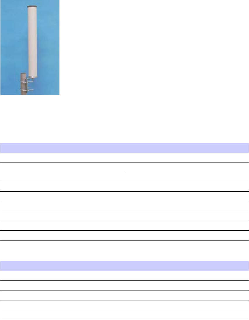
PMP320HDW2v1
7-27
Preliminary
JUL
2010
PMP
320
Hardware
Installation
Omni
Directional
Base
Station
Antenna
Figure
7-4
Omni
Directional
Base
Station
Antenna
Identification
G1_omnipolemn
t
view
.
eps
Specifications
Table
7-5
Omni
Directional
Base
Station
Antenna
Electrical
Specification
Specification
Value
Frequency
range
3.3-
3.8
GHz
GAIN
,
typ.
9.5
dBi@3.4-3.8
9
dBi@3.3-3.4
VSWR,
max.
2
:
1
P
olarization
Linear
,
V
ertical
3
dB
Beam-W
idth,
H-Plane,
typ.
Omni
Directional
3
dB
Beam-W
idth,
E-Plane,
typ.
10°
Input
power,
max
50
W
att
Input
Impedance
50
Ohm
Table
7-6
Omni
Directional
Base
Station
Antenna
Mechanical
Specification
Specification
Value
Dimensions
(HxDia.)
470
x
66
mm
(18.5”
x
2.
5”)
W
eight
350
gr
.
Connector
N-
Type,
F
emale
R
adome
UV
Protected
,
Plastic
Mount
2.5”
PM
(End)
A
ttachment
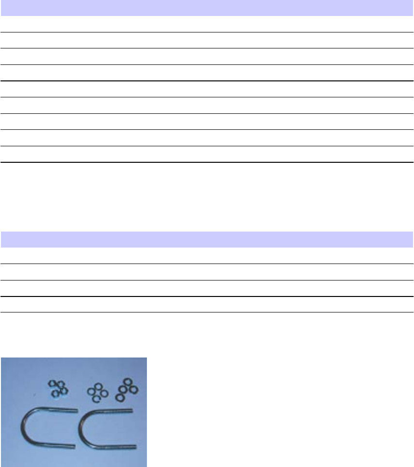
7-28
PMP320HDW2v1
Pr
e
limin
a
r
y
J
UL
2
0
1
0
Omni
Directional
Base
Station
Antenna
Chapter
7:
Connectorized
CSM
Antenna
Installation
Instructions
Table
7-7
Omni
Directional
Base
Station
Antenna
Environmental
Specification
Specification
Value
Operating
T
emperature
R
ange
-
40°C
to
+
65°C
V
ibration
According
to
IEC
60721-3-4
W
ind
Load
200
km/h
(survival)
Flammability
UL94
W
ater
Proofing
IP-65
Humidity
ETS
300
019-1-4,
EN
302
085
(annex
A.1.1)
Salt
F
og
According
to
IEC
68-2-11
Ice
and
Snow
25mm
radial
(survival)
Service
Life
>10
years
Parts
List
Table
7-8
Omni
Directional
Base
Station
Antenna
Pole
Mounting
Parts
List
Quantity
Description
2
U
-brackets
4
Plain
washers
4
Helical
spring
lock
washers
4
Hex
nuts
Figure
7-5
Omni
Directional
Base
Station
Antenna
Parts
Identification
G1_omnipolemn
t
par
t
sid
.
eps
Tools
Hex
wrench
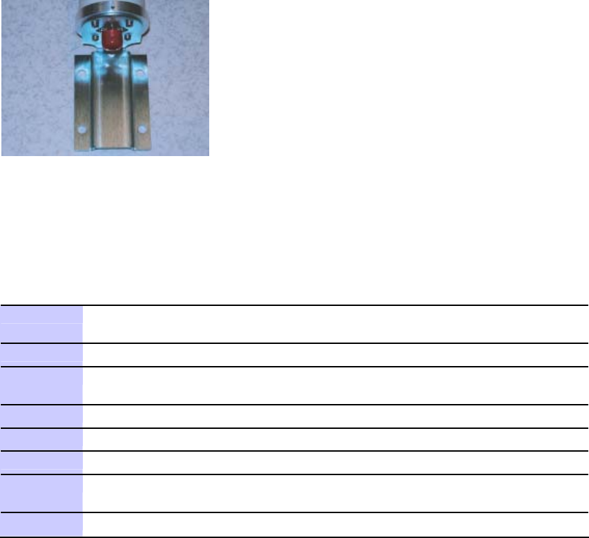
PMP
320
Hardware
Installation
Omni
Directional
Base
Station
Antenna
PMP320HDW2v1
7-29
J
UL
2
0
1
0
Pr
e
limin
a
r
y
1
Locate
the
area
of
the
pole
where
the
Omni
Directional
Base
Station
Antenna
will
be
mounted
to
the
pole.
2
Slide
the
U-bracket
around
the
pole.
3
Align
the
Omni
Directional
Base
Station
antenna
bracket
and
pass
the
U-bracket
through
the
bracket
of
the
antenna.
4
Slide
the
plain
washers
on
the
U-bracket.
5
Slide
the
helical
locking
washers
on
the
U-bracket
6
Use
the
nuts
to
securely
fasten
the
antenna
bracket
to
the
U-bracket
7
Repeat
step
2
through
step
step
6
for
the
second
bracket.
Repeat
these
steps
for
the
second
antenna.
8
Connect
the
antenna
to
the
connectorized
CSM
using
the
instructions
in
the
Antenna
Mounting
Instructions
Use
the
following
procedure
to
mount
the
Omni
Directional
Base
Station
Antenna
to
a
pole.
Note
that
two
Omni
Directional
Base
Station
Antennas
are
needed
to
support
the
Connectorized
PMP
320
CSM.
Figure
7-6
Omni
Directional
Base
Station
Antenna
Bracket
Identification
G1_omnipolemn
t
bracke
t
conn
.
eps
Procedure
7-2
Procedure
to
mount
an
Omni
Directional
Base
Station
Antenna
to
a
pole
Connectorized
CSM
Installation
chapter
.
Omni
Directional
Base
Station
Antenna
Chapter
7:
Connectorized
CSM
Antenna
Installation
Instructions
7-30
PMP320HDW2v1
Preliminary
JUL
2010

PMP320HDW2v1
7-31
J
UL
2
0
1
0
Pr
e
limin
a
r
y
Chapter
8
Regulatory,
Legal,
and
Safety
Notices
■ ■ ■ ■ ■ ■ ■ ■ ■ ■ ■ ■ ■ ■ ■ ■ ■ ■ ■ ■ ■ ■ ■ ■ ■ ■ ■ ■ ■ ■ ■ ■ ■ ■ ■
■ ■ ■ ■ ■ ■ ■ ■ ■ ■ ■ ■ ■ ■ ■ ■ ■ ■ ■ ■ ■ ■ ■ ■ ■ ■
■
■
■
■
7-32
PMP320HDW2v1
Preliminary
JUL
2010
IMPORTANT
NOTE
ON
MODIFICATIONS
Chapter
8:
Regulatory,
Legal,
and
Safety
Notices
IMPORTANT
NOTE
ON
MODIFICATIONS
■ ■ ■ ■ ■ ■ ■ ■ ■ ■ ■ ■ ■ ■ ■ ■ ■ ■ ■ ■ ■ ■ ■ ■ ■ ■ ■ ■ ■ ■ ■ ■ ■ ■ ■
■ ■ ■ ■ ■ ■ ■ ■ ■ ■ ■ ■ ■ ■ ■ ■ ■ ■ ■ ■ ■ ■ ■ ■ ■ ■
■
Intentional
or
unintentional
changes
or
modifications
to
the
equipment
must
not
be
made
unless
under
the
express
consent
of
the
party
responsible
for
compliance.
Any
such
modifications
could
void
the
user’s
authority
to
operate
the
equipment
and
will
void
the
manufacturer’s
warrant
y
.
Federal Communication Commission Interference Statement
This equipment has been tested and found to comply with the limits for a Class B digital device, pursuant to Part 15
of the FCC Rules. These limits are designed to provide reasonable protection against harmful interference in a
residential installation. This equipment generates, uses and can radiate radio frequency energy and, if not installed
and used in accordance with the instructions, may cause harmful interference to radio communications. However,
there is no guarantee that interference will not occur in a particular installation. If this equipment does cause
harmful interference to radio or television reception, which can be determined by turning the equipment off and on,
the user is encouraged to try to correct the interference by one of the following measures:
- Reorient or relocate the receiving antenna.
- Increase the separation between the equipment and receiver.
- Connect the equipment into an outlet on a circuit different from that to which the receiver is connected.
- Consult the dealer or an experienced radio/TV technician for help.
FCC Caution: Any changes or modifications not expressly approved by the party responsible for compliance could
void the user's authority to operate this equipment.
This device complies with Part 15 of the FCC Rules. Operation is subject to the following two conditions: (1) This
device may not cause harmful interference, and (2) this device must accept any interference received, including
interference that may cause undesired operation.
IMPORTANT NOTE:
FCC Radiation Exposure Statement:
3630SMC complies with FCC radiation exposure limits set forth for an uncontrolled environment. This equipment
should be installed and operated with minimum distance 20 cm between the radiator & your body.
This transmitter must not be co-located or operating in conjunction with any other antenna or transmitter.
The availability of some specific channels and/or operational frequency bands are country dependent and are
firmware programmed at the factory to match the intended destination. The firmware setting is not accessible by
the end user.
Industry Canada statement:
This device complies with RSS-192 of the Industry Canada Rules. Operation is subject to the following two
conditions:
(1) This device may not cause harmful interference, and (2) this device must accept any interference received,
including interference that may cause undesired operation.
IMPORTANT NOTE:
Radiation Exposure Statement:
This equipment complies with Canada radiation exposure limits set forth for an uncontrolled environment. This
equipment should be installed and operated with minimum distance 81 cm between the radiator & your body.
This device has been designed to operate with an antenna having a maximum gain of 22 dBi. Antenna having a
higher gain is strictly prohibited per regulations of Industry Canada. The required antenna impedance is 50 ohms.

PMP320HDW2v1
8-33
Preliminary
JUL
2010
PMP
320
Hardware
Installation
NATIONAL
AND
REGIONAL
REGULATORY
NOTICES
NATIONAL
AND
REGIONAL
REGULATORY
NOTICES
■ ■ ■ ■ ■ ■ ■ ■ ■ ■ ■ ■ ■ ■ ■ ■ ■ ■ ■ ■ ■ ■ ■ ■ ■ ■ ■ ■ ■ ■ ■ ■ ■ ■ ■ ■
■ ■ ■ ■ ■ ■ ■ ■ ■ ■ ■ ■ ■ ■ ■ ■ ■ ■ ■ ■ ■ ■ ■ ■ ■
■
U.S.
Federal
Communication
Commission
(FCC)
Notification
This
device
complies
with
P
art
15
of
the
US
FCC
Rules
and
Regulations.
Operation
is
subject
to
the
following
two
conditions:
1.
This
device
may
not
cause
harmful
interference
and
2.
This
device
must
accept
any
interference
received,
including
interference
that
may
cause
undesired
operation.
This
equipment
has
been
tested
and
found
to
comply
with
the
limits
for
a
Class
B
digital
device,
pursuant
to
P
art
15
of
the
US
FCC
Rules.
These
limits
are
designed
to
provide
reasonable
protection
against
harmful
interference
in
a
residential
installation.
This
equipment
generates,
uses,
and
can
radiate
radio
-
frequency
energy
and,
if
not
installed
and
used
in
accordance
with
these
instructions,
may
cause
harmful
interference
to
radio
communications.
If
this
equipment
does
cause
harmful
interference
to
radio
or
television
reception,
which
can
be
determined
by
turning
the
equipment
on
and
off
,
the
user
is
encouraged
to
correct
the
interference
by
one
or
more
of
the
following
measures:
•
Increase
the
separation
between
the
affected
equipment
and
the
unit;
•
Connect
the
affected
equipment
to
a
power
outlet
on
a
different
circuit
from
that
which
the
receiver
is
connected
to;
•
Consult
the
dealer
and/or
experienced
radio/TV
technician
for
help.
Table
8-1
FCC
IDs
and
the
specific
configurations
FCC
ID
Operating
Frequency
Model
Number
Antenna
Gain
Channel
Size
Maximum
T
ransmitter
Output
Power
Maximum
allowed
EIRP
ABZ89FT7632
3.650
to
3.675
GHz
ABZ89FT7633
3.650
GHz
to
3.675
GHz
3630APC
16.5
dBi
3630SM
14.5
dBi
10
MHz
22.91
dBm
NA
7
MHz
21.35
dBm
NA
5
MHz
19.81
dBm
NA
3.5
MHz
18.33
dBm
NA
10
MHz
10
MHz
10
W
(40
dBm
C
o
n
tinued
7
MHz
24
dBm
7
W
(38.5
dBm)
5
MHz
22.5
dBm
5
W
(37
dBm)
3.5
MHz
20.9
dBm
3.5
W
(35.4
dBm)

8-34
PMP320HDW2v1
Preliminary
JUL
2010
10MHz
26.5
36
7MHz 25
34.5
5MHz 24
33.5
3.5MHz 23
32.5
10MHz
14
36
7MHz 13
35
5MHz 12
34
3.5MHz 11.5
33.5
Industry
Canada
Notification
Chapter
8:
Regulatory,
Legal,
and
Safety
Notices
Table
8-1
FCC
IDs
and
the
specific
configurations
(Continued)
Maximum
FCC
ID
Operating
Frequency
Model
Number
Antenna
Gain
Channel
Size
T
ransmitter
Output
Power
Maximum
allowed
EIRP
ABZ89FT7636
3.650
GHz
to
3.675
GHz
3630SMC
9.5
ABZ89FT7636
3.650
GHz
to
3630SMC 22
3.675
GHz
Industry
Canada
Notification
This
device
is
approved
for
use
in
Canada
in
the
licensed
frequencies
from
3.450
GHz
to
3.700
GHz.
It
is
undergoing
Industry
Canada
approval
for
use
in
the
3.65
GHz
band,
and
may
not
be
used
in
that
band
until
Industry
Canada
approval
is
granted.
Operation
is
subject
to
the
following
two
conditions:
•
This
device
may
not
cause
harmful
interference
and
•
This
device
must
accept
any
interference
received,
including
interference
that
may
cause
undesired
operation.
This
equipment
has
been
tested
and
found
to
comply
with
the
limits
for
a
Class
B
digital
device.
These
limits
are
designed
to
provide
reasonable
protection
against
harmful
interference
in
a
residential
installation.
This
equipment
generates,
uses,
and
can
radiate
radio
-
frequency
energy
and
if
not
installed
and
used
in
accordance
with
these
instructions,
may
cause
harmful
interference
to
radio
communications.
If
this
equipment
does
cause
harmful
interference
to
radio
or
television
reception,
which
can
be
determined
by
turning
the
equipment
on
and
off
,
the
user
is
encouraged
to
correct
the
interference
by
one
or
more
of
the
following
measures:
•
Increase
the
separation
between
the
affected
equipment
and
the
unit;
•
Connect
the
affected
equipment
to
a
power
outlet
on
a
different
circuit
from
that
which
the
receiver
is
connected
to;
•
Consult
the
dealer
and/or
experienced
radio/TV
technician
for
help.
T
o
reduce
potential
radio
interference
to
other
users,
the
antenna
type
and
its
gain
should
be
chosen
so
its
Equivalent
Isotropic
R
adiated
P
ower
(EIRP)
is
not
more
than
that
permitted
for
successful
communication.
For 3630APC (3600~3650 MHz)
This device has been designed to operate with an antenna having a maximum gain of 17 dBi. Antenna having a higher gain
is strictly prohibited per regulations of Industry Canada. The required antenna impedance is 50 ohms.
For 3630APC (3650~3700MHz)
This device has been designed to operate with an antenna having a maximum gain of 16.5 dBi. Antenna having a higher
gain is strictly prohibited per regulations of Industry Canada. The required antenna impedance is 50 ohms.
For 3530SMC/3630SMC
This device has been designed to operate with an antenna having a maximum gain of 22 dBi. Antenna having a higher gain
is strictly prohibited per regulations of Industry Canada. The required antenna impedance is 50 ohms.
PMP
320
Hardware
Installation
European
Union
Notification

PMP320HDW2v1
8-35
Preliminary
JUL
2010
Table
8-2
Industry
Canada
Certification
Numbers
and
the
specific
configuration
IC
ID
Operating
Frequency
Model
number Antenna
Gain Channel
Size
Maximum
Allowed
EIRP
Maximum
Transmitter
Output
power
109 W-3530APC 3450~3600MHz 3530 APC
16.5 dBi
connectorized
any NA 27dBm
(500mW)
109W-3630APC 3600~3650MHz 3636APC 17
dBi
any NA 27dBm
(500mW)
109W-3630APC 3650~3700MHz 3636APC 16.5
dBi
any NA 25dBm
(316mW)
109W-3530SM 3450~3600MHz 3530SM
14.5
dBi
NA NA 27dBm
(500mW)
109W-3630SM 3600~3700MHz 3630SM
14.5
dBi
NA NA 27dBm
(500mW)
109W
-
3530SMC
3450~3600MHz 3530SMC 22 dBi NA NA 27 dBm
(500mW)
109W-3630SMC 3600~3700MHz 3639SMC NA NA NA TBD
European
Union
Notification
The
relevant
Declaration
of
Conformity
can
be
found
at
http://motorola.wirelessbroadbandsupport.com/doc.php
Equipment
Disposal
Please
do
not
dispose
of
Electronic
and
Electric
Equipment
or
Electronic
and
Electric
Accessories
with
your
household
waste.
In
some
countries
or
regions,
collection
systems
have
been
set
up
to
handle
waste
of
electrical
and
electronic
equipment.
In
European
Union countries,
please
contact
your
local
equipment
supplier
representative
or
service
center
for
information
about
the
waste
collection
system
in
your
countr
y
.
EU
Declaration
of
Conformity
for
RoHS
Compliance
Motorola
hereb
y
,
declares
that
these
Motorola
products
are
in
compliance
with
the
essential
requirements
and
other
relevant
provisions
of
Directive
2002/95/EC
,
Restriction
of
the
use
of
certain
Hazardous
Substances
(RoHS)
in
electrical
and
electronic
equipment.
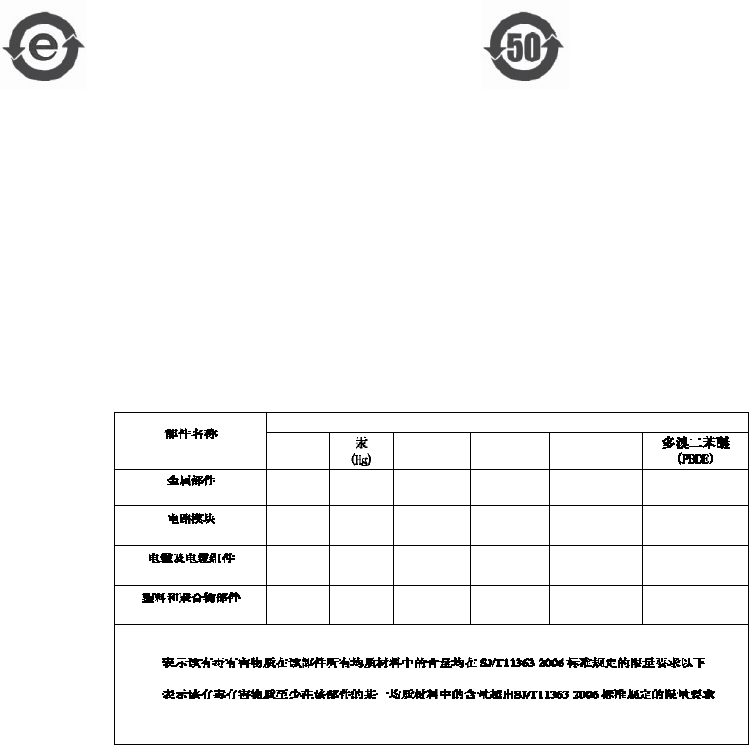
8-36
PMP320HDW2v1
Preliminary
JUL
2010
Products
Labeling
and
Disclosure
Table
for
China
Chapter
8:
Regulatory,
Legal,
and
Safety
Notices
The
relevant
Declaration
of
Conformity
can
be
found
at
http://motorola.wirelessbroadband-
.
support.com/doc.php
Labeling
and
Disclosure
Table
for
China
The
P
eople’s
Republic
of
China
requires
that
Motorola’s
products
comply
with
ChinaManagement
Methods
(CMM)
environmental
regulations.
(China
Management
Methods
refers
to
the
regulation
Management
Methods
for
Controlling
P
ollution
by
Electronic
Information
.)
T
wo
items
are
used
to
demonstrate
compliance
-
the
label,
and
the
disclosure
table
.
T
able
6
3
Disclosure
table
The
label
is
placed
in
a
customer
visible
position
on
the
product.
•
Logo
1
means
that
the
product
contains
no
substances
in
excess
of
the
maximum
concentration
value
for
materials
identified
in
the
China
Management
Methods
regulation.
•
Logo
2
means
that
the
product
may
contain
substances
in
excess
of
the
maximum
concentration
value
for
materials
identified
in
the
China
Management
Methods
regulation,
and
has
an
Environmental
Friendly
Use
P
eriod
(EFUP)
in
years,
fifty
years
in
the
example
shown.
Logo
1
Logo
2
The
Environmental
Friendly
Use
P
eriod
(EFUP)
is
the
period
(in
years)
during
which
the
T
oxic
and
Hazardous
Substances
(T&HS)
contained
in
the
Electronic
Information
Product
(EIP)
will
not
leak
or
mutate
causing
environmental
pollution
or
bodily
injury
from
the
use
of
the
EI
P
.
The
EFUP
indicated
by
the
Logo
2
label
applies
to
a
product
and
all
its
parts.
Certain
field
-
replaceable
parts,
such
as
battery
modules,
can
have
a
different
EFUP
and
are
marked
separatel
y
.
The
Disclosure
table
is
intended
to
communicate
compliance
with
only
China
requirements;
it
is
not
intended
to
communicate
compliance
with
EU
RoHS
or
any
other
environmental
requirements.
Figure
8-1
Disclosure
Table
PMP320HDW2v1
8-37
Preliminary
JUL
2010
,
Fields
PMP
320
Hardware
Installation
RF
EXPOSURE
SEPARATION
DISTANCES
RF
EXPOSURE
SEPARATION
DISTANCES
■ ■ ■ ■ ■ ■ ■ ■ ■ ■ ■ ■ ■ ■ ■ ■ ■ ■ ■ ■ ■ ■ ■ ■ ■ ■ ■ ■ ■ ■ ■ ■ ■ ■ ■
■ ■ ■ ■ ■ ■ ■ ■ ■ ■ ■ ■ ■ ■ ■ ■ ■ ■ ■ ■ ■ ■ ■ ■ ■ ■
■
■
T
o
protect
from
overexposure
to
RF
energ
y
,
an
AP
must
be
installed
to
provide
a
separation
distance
of
at
least
50
cm
(
~20
in)
from
all
persons
In
addition,
do
not
collocate
within
20
cm
(4
in)
of
any
other
antenna
or
transmitter
.
T
o
protect
from
overexposure
to
RF
energ
y
,
an
SM
must
be
installed
to
provide
a
separation
distance
of
at
least
50
cm
(
~20
in)
from
all
persons
and
must
not
be
collocated
or
operating
with
any
other
antenna
or
transmitter
.
The
following
section
and
table
provide
details
and
discussion
on
the
separate
distance
calculations.
To protect from overexposure to EU RF energy, An 3530SMC must be installed to provide a separation
distance of at least 82 cm from all persons and must be not collocated or operating with any other
antenna or transmitter.
To protect from overexposure to EU RF energy, An 3630SMC must be installed to provide a separation
distance of at least 120 cm from all persons and must be not collocated or operating with any other
antenna or transmitter.
Details
of
Exposure
Separation
Distances
Calculations
and
Power
Compliance
Margins
Limits
and
guidelines
for
RF
exposure
come
from:
•
US
FCC
limits
for
the
general
population.
See
the
FCC
web
site
at
http://ww
w
.fcc.gov
the
policies,
guidelines,
and
requirements
in
P
art
1
of
Title
47
of
the
Code
of
F
ederal
and
Regulations,
as
well
as
the
guidelines
and
suggestions
for
evaluating
compliance
in
FCC
OET
Bulletin
65.
•
Health
Canada
limits
for
the
general
population.
See
the
Health
Canada
web
site
at
http://ww
w
.hc
-
sc.gc.ca/rpb
and
Safety
Code
6.
•
ICNIRP
(International
Commission
on
Non
-
Ionizing
R
adiation
Protection)
guidelines
for
the
general
public.
See
the
ICNIRP
web
site
at
http://ww
w
.icnirp.de/
and
Guidelines
for
Limiting
Exposure
to
Time
-
V
arying
Electric,
Magnetic,
and
Electromagnetic
.
The
applicable
power
density
exposure
limits
from
the
documents
referenced
above
is
10
W/m2.
P
eak
power
density
in
the
far
field
of
a
radio
frequency
point
source
is
calculated
as:
Figure
8-2
Peak
power
density
calculation

8-38
PMP320HDW2v1
Preliminary
JUL
2010
T
able
8
-
3
shows
calculated
minimum
separation
distances
d,
recommended
distances
and
resulting
power
compliance
margins
for
each
frequency
band
and
antenna
combination.
Details
of
Exposure
Separation
Distances
Calculations
and
Power
Compliance
Margins
Chapter
8:
Regulatory,
Legal,
and
Safety
Notices
Table
8-3
Calculated
exposure
distances
and
power
compliance
margins
P( dBm ) P( W ) G S Distance (cm ,
Calculated )
3630APC 25.1 0.324 16.5 10 33.92
3630SM 27.06 0.508 14.5 10 33.76
These
are
conservative
distances:
•
They
are
along
the
beam
direction
(the
direction
of
greatest
energy).
Exposure
to
the
sides
and
back
of
the
module
is
significantly
less.
•
In
the
case
of
collocated
AP
s,
they
assume
all
AP
s
are
oriented
in
the
same
direction,
which
is
a
worst
-
case
calculation.
•
They
meet
or
exceed
sustained
exposure
limits
for
the
general
population
(not
just
short
-
term
occupational
exposure
limits).
•
The
calculated
compliance
distance
d
is
overestimated
because
the
far
-
field
equation
models
the
antenna(s)
as
a
point
source
and
neglects
the
physical
dimension
of
the
antenna(s).
Table
8-4
Exposure
separation
distances
Module
T
ype
Separation
Distance
from
Persons
R
adio
Module
with
integrated
antenna
A
t
least
20
cm
(approximately
8
inches)
Module
with
Reflector
Dish
A
t
least
1.5
m
(approximately
60
inches
or
5
feet)
Module
with
LENS
A
t
least
0.5
m
(approximately
20
inches)
Antenna
of
connectorized
5.7
GHz
AP
A
t
least
30
cm
(approximately
12
inches)
Antenna
of
connectorized
or
integrated
900
MHz
module
A
t
least
60
cm
(approximately
24
inches)
Indoor
900
MHz
SM
A
t
least
10
cm
(approximately
4

PMP320HDW2v1
8-39
Preliminary
JUL
2010
inches)
PMP
320
AP
A
t
least
50
cm
(approximately
20
inches)
8-40
PMP320HDW2v1
Preliminary
JUL
2010
PMP
320
Hardware
Installation
Software
License
Terms
and
Conditions
Software
License
Terms
and
Conditions
■ ■ ■ ■ ■ ■ ■ ■ ■ ■ ■ ■ ■ ■ ■ ■ ■ ■ ■ ■ ■ ■ ■ ■ ■ ■ ■ ■ ■ ■ ■ ■ ■ ■ ■
■ ■ ■ ■ ■ ■ ■ ■ ■ ■ ■ ■ ■ ■ ■ ■ ■ ■ ■ ■ ■ ■ ■ ■ ■ ■
■
■
ONL
Y
OPEN
THE
P
ACK
AGE,
OR
USE
THE
SOFTW
ARE
AND
RELATED
PRODUCT
IF
YOU
ACCEPT
THE
TERMS
OF
THIS
LICENSE.
B
Y
BREAKING
THE
SEAL
ON
THIS
DISK
KIT
/
CDROM,
OR
IF
YOU
USE
THE
SOFTW
ARE
OR
RELATED
PRODUC
T
,
YOU
ACCEPT
THE
TERMS OF
THIS
LICENSE
AGREEMEN
T
.
IF
YOU
DO
NOT
AGREE
TO
THESE
TERMS
,
DO
NOT
USE
THE
SOFTW
ARE
OR
RELATED
PRODUCT
;
INSTEAD
,
RETURN
THE
SOFTW
ARE
TO
PLACE
OF
P
URCHASE
FOR
A
FULL
REFUND
.
THE
FOLLOWING
AGREEMENT
IS
A
LEGAL
AGREEMENT
BETWEEN
YOU
(EITHER
AN
INDIVIDU
AL
OR
ENTITY),
AND
MOTOROLA,
INC
.
(FOR
ITSELF
AND
ITS
LICENSORS).
THE
RIGHT
TO
USE
THIS
PRODUCT
IS
LICENSED
ONL
Y
ON
THE
CONDITION
THA
T
YOU
AGREE
TO
THE
FOLLOWING
TERMS
.
No
w
,
therefore,
in
consideration
of
the
promises
and
mutual
obligations
contained
herein,
and
for
other
good
and
valuable
consideration,
the
receipt
and
sufficiency
of
which
are
hereby
mutually
acknowledged,
you
and
Motorola
agree
as
follows:
Grant
of
License.
Subject
to
the
following
terms
and
conditions,
Motorola,
Inc.,
grants
to
you
a
personal,
revocable,
non
-
assignable,
non
-
transferable,
non
-
exclusive
and
limited
license
to
use
on
a
single
piece
of
equipment
only
one
copy
of
the
software
contained
on
this
disk
(which
may
have
been
pre
-
loaded
on
the
equipment)(Software).
Y
ou
may
make
two
copies
of
the
Software,
but
only
for
backup,
archival,
or
disaster
recovery
purposes.
On
any
copy
you
make
of
the
Software,
you
must
reproduce
and
include
the
copyright
and
other
proprietary
rights
notice
contained
on
the
copy
we
have
furnished
you
of
the
Software.
Ownership.
Motorola
(or
its
supplier)
retains
all
title,
ownership
and
intellectual
property
rights
to
the
Software
and
any
copies,
including
translations,
compilations,
derivative
works
(including
images)
partial
copies
and
portions
of
updated
works.
The
Software
is
Motorola’s
(or
its
supplier's)
confidential
proprietary
information.
This
Software
License
Agreement
does
not
convey
to
you
any
interest
in
or
to
the
Software,
but
only
a
limited
right
of
use.
Y
ou
agree
not
to
disclose
it
or
make
it
available
to
anyone
without
Motorola’s
written
authorization.
Y
ou
will
exercise
no
less
than
reasonable
care
to
protect
the
Software
from
unauthorized
disclosure.
Y
ou
agree
not
to
disassemble,
decompile
or
reverse
engineer,
or
create
derivative
works
of
the
Software,
except
and
only
to
the
extent
that
such
activity
is
expressly
permitted
by
applicable
law
.
Termination
.
This
License
is
effective
until
terminated.
This
License
will
terminate
immediately
without
notice
from
Motorola
or
judicial
resolution
if
you
fail
to
comply
with
any
provision
of
this
License.
Upon
such
termination
you
must
destroy
the
Software,
all
accompanying
written
materials
and
all
copies
thereof
,
and
the
sections
entitled
Limited
W
arrant
y
,
Limitation
of
Remedies
and
Damages,
and
General
will
survive
any
termination.
Limited
W
arranty
.
Motorola
warrants
for
a
period
of
ninety
(90)
days
from
Motorola’s
or
its
customer’s
shipment
of
the
Software
to
you
that
(i)
the
disk(s)
on
which
the
Software
is
recorded
will
be
free
from
defects
in
materials
and
workmanship
under
normal
use
and
(ii)
the
Software,
under
normal
use,
will
perform
substantially
in
accordance
with
Motorola’s
published
specifications
for
that
release
level
of
the
Software.
The
written
materials
are
provided
"AS
IS"
and
without
warranty
of
any
kind.
Motorola's
entire
liability
and
your
sole
and
exclusive
remedy
for
any
breach
of
the
foregoing
limited
warranty
will
be,
at
Motorola's
option,
replacement
of
the
disk(s),
provision
of
downloadable
patch
or
replacement
code,
or
refund
of
the
unused
portion
of
your
bargained
for
contractual
benefit
up
to
the
amount
paid
for
this
Software
License.
PMP320HDW2v1
8-41
Preliminary
JUL
2010
Software
License
Terms
and
Conditions
Chapter
8:
Regulatory,
Legal,
and
Safety
Notices
THIS
LIMITED
W
ARRANTY
IS
THE
ONL
Y
W
ARRANTY
PRO
VIDED
B
Y
MOTOROLA,
AND
MOTOROLA
AND
ITS
LICENSORS
EXPRES
SL
Y
DISCLAIM
ALL
OTHER
WARRANTIES
,
EITHER
EXPRES
S
OF
IMPLIED
,
INCL
UDING
BUT
NOT
LIMITED
TO
IMPLIED
WARRANTIES
OF
MERCHANT
ABILITY
AND
FITNES
S
FOR
A
P
AR
TICULAR
P
URPOSE
AND
NONINFRINGEMEN
T
.
MOTOROLA
DOES
NOT
WARRANT
THA
T
THE
OPERA
TION
OF
THE
SOFTW
ARE
WILL
BE
UNINTERRUPTED
OR
ERRORFREE,
OR
THA
T
DEFECTS
IN
THE
SOFTW
ARE
WILL
BE
CORRECTED
.
NO
ORAL
OR
WRIT
TEN
REPRESENT
A
TIONS
MADE
B
Y
MOTOROLA
OR
AN
AGENT
THEREOF
SHALL
CREA
TE
A
W
ARRANTY
OR
IN
ANY
WA
Y
INCREASE
THE
SCOPE
OF
THIS
WARRANT
Y
.
MOTOROLA
DOES
NOT
WARRANT
ANY
SOFTW
ARE
THA
T
HAS
BEEN
OPERA
TED
IN
EX
CES
S
OF
SPECIFICA
TIONS
,
DAMAGED
,
MISUSED
,
NEGLECTED
,
OR
IMPROPERL
Y
INST
ALLED
.
BECAUSE
SOME
JURISDICTIONS
DO
NOT
ALLOW
THE
EX
CL
USION
OR
LIMIT
A
TION
OF
IMPLIED
WARRANTIES
,
THE
AB
O
VE
LIMIT
A
TIONS
MA
Y
NOT
APPL
Y
TO
YOU
.
Limitation
of
Remedies
and
Damages
.
Regardless
of
whether
any
remedy
set
forth
herein
fails
of
its
essential
purpose,
IN
NO
EVENT
SHALL
MOTOROLA
OR
ANY
OF
THE
LICENSORS
,
DIRECTORS
,
OFFICERS
,
EMPLOYEES
OR
AFFILIA
TES
OF
THE
FOREGOING
BE
LIABLE
TO YOU
FOR
ANY
CONSEQUENTIAL,
INCIDENT
AL,
INDIREC
T
,
SPECIAL
OR
SIMILAR
DAMAGES
WHA
TSOEVER
(including,
without
limitation,
damages
for
loss
of
business
profits,
business
interruption,
loss
of
business
information
and
the
like),
whether
foreseeable
or
unforeseeable,
arising
out
of
the
use
or
inability
to
use
the
Software
or
accompanying
written
materials,
regardless
of
the
basis
of
the
claim
and
even
if
Motorola
or
a
Motorola
representative
has
been
advised
of
the
possibility
of
such
damage.
Motorola's
liability
to
you
for
direct
damages
for
any
cause
whatsoever
,
regardless
of
the
basis
of
the
form
of
the
action,
will
be
limited
to
the
price
paid
for
the
Software
that
caused
the
damages.
THIS
LIMIT
A
TION
WILL
NOT
APPL
Y
IN
CASE
OF
PERSONAL
INJUR
Y
ONL
Y
WHERE
AND
TO
THE
EXTENT
THA
T
APPLICABLE
LA
W
REQUIRES
SUCH
LIABILIT
Y
.
BECAUSE
SOME
JURISDICTIONS
DO
NOT
ALLOW
THE
EX
CL
USION
OR
LIMIT
A
TION
OF
LIABILITY
FOR
CONSEQUENTIAL
OR
INCIDENT
AL
DAMAGES
,
THE
AB
O
VE
LIMIT
A
TION
MA
Y
NOT
APPL
Y
TO
YOU
.
Maintenance
and
Support
.
Motorola
shall
not
be
responsible
for
maintenance
or
support
of
the
software.
By
accepting
the
license
granted
under
this
agreement,
you
agree
that
Motorola
will
be
under
no
obligation
to
provide
any
support,
maintenance
or
service
in
connection
with
the
Software
or
any
application
developed
by
you.
Any
maintenance
and
support
of
the
Related
Product
will
be
provided
under
the
terms
of
the
agreement
for
the
Related
Product.
T
ransfer
.
In
the
case
of
software
designed
to
operate
on
Motorola
equipment,
you
may
not
transfer
the
Software
to
another
party
except:
(1)
if
you
are
an
end
-
user,
when
you
are
transferring
the
Software
together
with
the
Motorola
equipment
on
which
it
operates;
or
2)
if
you
are
a
Motorola
licensed
distributor
,
when
you
are
transferring
the
Software
either
together
with
such
Motorola
equipment
or
are
transferring
the
Software
as
a
licensed
duly
paid
for
upgrade,
update,
patch,
new
release,
enhancement
or
replacement
of
a
prior
version
of
the
Software.
If
you
are
a
Motorola
licensed
distributor
,
when
you
are
transferring
the
Software
as
permitted
herein,
you
agree
to
transfer
the
Software
with
a
license
agreement
having
terms
and
conditions
no
less
restrictive
than
those
contained
herein.
Y
ou
may
transfer
all
other
Software,
not
otherwise
having
an
agreed
restriction
on
transfer
,
to
another
part
y
.
However,
all
such
transfers
of
Software
are
strictly
subject
to
the
conditions
precedent
that
the
other
party
agrees
to
accept
the
terms
and
conditions
of
this
License,
and
you
destroy
any
copy
of
the
Software
you
do
not
transfer
to
that
part
y
.
Y
ou
may
not
sublicense
or
otherwise
transfer
,
rent
or
lease
the
Software
without
our
written
consent.
Y
ou
may
not
transfer
the
Software
in
violation
of
any
laws,
regulations,
export
controls
or
economic
sanctions
imposed
by
the
US
Government.
Right
to
Audit
.
Motorola
shall
have
the
right
to
audit
annuall
y
,
upon
reasonable
advance
notice
and
during
normal
business
hours,
your
records
and
accounts
to
determine
compliance
with
the
terms
of
this
Agreement.
Export
Controls
.
Y
ou
specifically
acknowledge
that
the
software
may
be
subject
to
United
States
and
other
country
export
control
laws.
Y
ou
shall
comply
strictly
with
all
requirements
of
all
applicable
export
control
laws
and
regulations
with
respect
to
all
such
software
and
materials.
8-42
PMP320HDW2v1
Preliminary
JUL
2010
PMP
320
Hardware
Installation
Software
License
Terms
and
Conditions
US
Government
Users
.
If
you
are
a
US
Government
user,
then
the
Software
is
provided
with
"RESTRICTED
RIGHTS"
as
set
forth
in
subparagraphs
(c)(1)
and
(2)
of
the
Commercial
Computer
Software
-
Restricted
Rights
clause
at
F
AR
52
227
-
19
or
subparagraph
(c)(1)(ii)
of
the
Rights
in
T
echnical
Data
and
Computer
Software
clause
at
DF
ARS
252.227
-
7013,
as
applicable.
Disputes
.
Y
ou
and
Motorola
hereby
agree
that
any
dispute,
controversy
or
claim,
except
for
any
dispute,
controversy
or
claim
involving
intellectual
propert
y
,
prior
to
initiation
of
any
formal
legal
process,
will
be
submitted
for
non
-
binding
mediation,
prior
to
initiation
of
any
formal
legal
process.
Cost
of
mediation
will
be
shared
equall
y
.
Nothing
in
this
Section
will
prevent
either
party
from
resorting
to
judicial
proceedings,
if
(i)
good
faith
efforts
to
resolve
the
dispute
under
these
procedures
have
been
unsuccessful,
(ii)
the
dispute,
claim
or
controversy
involves
intellectual
propert
y
,
or
(iii)
interim
relief
from
a
court
is
necessary
to
prevent
serious
and
irreparable
injury
to
that
party
or
to
others.
General
.
Illinois
law
governs
this
license.
The
terms
of
this
license
are
supplemental
to
any
written
agreement
executed
by
both
parties
regarding
this
subject
and
the
Software
Motorola
is
to
license
you
under
it,
and
supersedes
all
previous
oral
or
written
communications
between
us
regarding
the
subject
except
for
such
executed
agreement.
It
may
not
be
modified
or
waived
except
in
writing
and
signed
by
an
officer
or
other
authorized
representative
of
each
part
y
.
If
any
provision
is
held
invalid,
all
other
provisions
shall
remain
valid,
unless
such
invalidity
would
frustrate
the
purpose
of
our
agreement.
The
failure
of
either
party
to
enforce
any
rights
granted
hereunder
or
to
take
action
against
the
other
party
in
the
event
of
any
breach
hereunder
shall
not
be
deemed
a
waiver
by
that
party
as
to
subsequent
enforcement
of
rights
or
subsequent
action
in
the
event
of
future
breaches.
PMP320HDW2v1
8-43
Preliminary
JUL
2010
Hardware
Warranty
in
US
Chapter
8:
Regulatory,
Legal,
and
Safety
Notices
Hardware
Warranty
in
US
■ ■ ■ ■ ■ ■ ■ ■ ■ ■ ■ ■ ■ ■ ■ ■ ■ ■ ■ ■ ■ ■ ■ ■ ■ ■ ■ ■ ■ ■ ■ ■ ■ ■ ■
■ ■ ■ ■ ■ ■ ■ ■ ■ ■ ■ ■ ■ ■ ■ ■ ■ ■ ■ ■ ■ ■ ■ ■ ■ ■
■
■
Motorola
US
offers
a
warranty
covering
a
period
of
1
year
from
the
date
of
purchase
by
the
customer.
If
a
product
is
found
defective
during
the
warranty
period,
Motorola
will
repair
or
replace
the
product
with
the
same
or
a
similar
model,
which
may
be
a
reconditioned
unit,
without
charge
for
parts
or
labor
.
8-44
PMP320HDW2v1
Preliminary
JUL
2010
PMP
320
Hardware
Installation
LIMIT
OF
LIABILITY
LIMIT
OF
LIABILITY
■ ■ ■ ■ ■ ■ ■ ■ ■ ■ ■ ■ ■ ■ ■ ■ ■ ■ ■ ■ ■ ■ ■ ■ ■ ■ ■ ■ ■ ■ ■ ■ ■ ■ ■
■ ■ ■ ■ ■ ■ ■ ■ ■ ■ ■ ■ ■ ■ ■ ■ ■ ■ ■ ■ ■ ■ ■ ■ ■ ■
■
■
IN
NO
EVENT
SHALL
MOTOROLA
BE
LIABLE
TO
YOU
OR
ANY
OTHER
P
AR
TY
FOR
ANY
DIREC
T
,
INDIREC
T
,
GENERAL,
SPECIAL,
INCIDENT
AL,
CONSEQUENTIAL,
EXEMPLAR
Y
OR
OTHER
DAMAGE
ARISING
OUT
OF
THE
USE
OR
INABILITY
TO
USE
THE
PRODUCT
(INCL
UDING,
WITHOUT
LIMIT
A
TION,
DAMAGES
FOR
LOS
S
OF
BUSINES
S
PROFITS
,
BUSINES
S
INTERRUPTION
,
LOS
S
OF
BUSINES
S
INFORMATION
OR
ANY
OTHER
PECUNIAR
Y
LOS
S
,
OR
FROM
ANY
BREACH
OF
WARRANT
Y
,
EVEN
IF
MOTOROLA
HAS
BEEN
AD
VISED
OF
THE
POS
SIBILITY
OF
SUCH
DAMAGES
.
(Some
states
do
not
allow
the
exclusion
or
limitation
of
incidental
or
consequential
damages,
so
the
above
exclusion
or
limitation
may
not
apply
to
you.)
IN
NO
CASE
SHALL
MOTOROLA
’S
LIABILITY
EX
CEED
THE
AMOUNT
YOU
P
AID
FOR
THE
PRODUC
T
.