Motorola Solutions 92FT3802 VRS750--Vehicular Repeater System User Manual Service Manual
Motorola Solutions, Inc. VRS750--Vehicular Repeater System Service Manual
Contents
- 1. Preliminary Users Manual
- 2. Service Manual
Service Manual

1
VRS 750
Vehicular Repeater System
Detailed Service Manual

2
Foreword
The information contained in this manual relates to the VRS750 Vehicular Repeater System, unless
otherwise specified. This manual provides sufficient information to enable service shop personnel to
troubleshoot and repair the VRS750 to the component level.
Safety Information
Before operating the VRS750, please read the “User Safety, Training, and General Information” section in
the front of this manual.
Manual Revisions
Changes which occur after this manual is printed are described in “FMRs.” These FMRs provide complete
information on changes, including pertinent parts list data.
Computer Software Copyrights
The Motorola products described in this manual may include copyrighted Motorola computer programs
stored in semiconductor memories or other media. Laws in the United States and other countries preserve
for Motorola certain exclusive rights for copyrighted computer programs, including, but not limited to,
the exclusive right to copy or reproduce in any form the copyrighted computer program. Accordingly, any
copyrighted Motorola computer programs contained in the Motorola products described in this manual
may not be copied, reproduced, modified, reverse-engineered, or distributed in any manner without the
express written permission of Motorola. Furthermore, the purchase of Motorola products shall not be
deemed to grant either directly or by implication, estoppel, or otherwise, any license under the
copyrights, patents or patent applications of Motorola, except for the normal non-exclusive license to use
that arises by operation of law in the sale of a product.

i
Table of Contents
➠
Foreword . . . . . . . . . . . . . . . . . . . . . . . . . . . . . . . . . . . . . . . . . . . . . . . . . . inside front cover
User Safety, Training, and General Information . . . . . . . . . . . . . . . . . . . . . . . . . . . . . . . iii
Safe Handling of CMOS Integrated-Circuit Devices . . . . . . . . . . . . . . . . . . . . . . . . . . . . . vi
Model Chart for the VRS750 . . . . . . . . . . . . . . . . . . . . . . . . . . . . . . . . . . . . . . . . . . . . . . . vii
VHF VRS750 Performance Specifications . . . . . . . . . . . . . . . . . . . . . . . . . . . . . . . . . . . . viii
UHF VRS750 Performance Specifications . . . . . . . . . . . . . . . . . . . . . . . . . . . . . . . . . . . . viii
Glossary of Terms. . . . . . . . . . . . . . . . . . . . . . . . . . . . . . . . . . . . . . . . . . . . . . . . . . . . . . . . . ix
List of Abbreviations and Acronyms . . . . . . . . . . . . . . . . . . . . . . . . . . . . . . . . . . . . . . . . . .x
1 - Introduction . . . . . . . . . . . . . . . . . . . . . . . . . . . . . . . . . . . . . . . . . . . . . . . . . . . . . . . . . . . 1
Description . . . . . . . . . . . . . . . . . . . . . . . . . . . . . . . . . . . . . . . . . . . . . . . . . . . . . . . . . . . . . . . . . . . 1
Ordering Information . . . . . . . . . . . . . . . . . . . . . . . . . . . . . . . . . . . . . . . . . . . . . . . . . . . . . . . . . . . 2
VRS Features . . . . . . . . . . . . . . . . . . . . . . . . . . . . . . . . . . . . . . . . . . . . . . . . . . . . . . . . . . . . . . . . . . 3
Mutually-Exclusive Features . . . . . . . . . . . . . . . . . . . . . . . . . . . . . . . . . . . . . . . . . . . . . . . . . . . . . . 3
2 - Installation . . . . . . . . . . . . . . . . . . . . . . . . . . . . . . . . . . . . . . . . . . . . . . . . . . . . . . . . . . . . 5
VRS Installation . . . . . . . . . . . . . . . . . . . . . . . . . . . . . . . . . . . . . . . . . . . . . . . . . . . . . . . . . . . . . . . . 5
Installation of the Mounting Trunnion . . . . . . . . . . . . . . . . . . . . . . . . . . . . . . . . . . . . . . . . . . . . . 6
VRS Antenna Installation . . . . . . . . . . . . . . . . . . . . . . . . . . . . . . . . . . . . . . . . . . . . . . . . . . . . . . . . 7
VRS750 Programming . . . . . . . . . . . . . . . . . . . . . . . . . . . . . . . . . . . . . . . . . . . . . . . . . . . . . . . . . . . 7
3 - VRS Operation . . . . . . . . . . . . . . . . . . . . . . . . . . . . . . . . . . . . . . . . . . . . . . . . . . . . . . . . . 19
General . . . . . . . . . . . . . . . . . . . . . . . . . . . . . . . . . . . . . . . . . . . . . . . . . . . . . . . . . . . . . . . . . . . . . 19
Control Unit . . . . . . . . . . . . . . . . . . . . . . . . . . . . . . . . . . . . . . . . . . . . . . . . . . . . . . . . . . . . . . . . . 19
Vehicle Interface Ports. . . . . . . . . . . . . . . . . . . . . . . . . . . . . . . . . . . . . . . . . . . . . . . . . . . . . . . . . . 20
VRS Access . . . . . . . . . . . . . . . . . . . . . . . . . . . . . . . . . . . . . . . . . . . . . . . . . . . . . . . . . . . . . . . . . . . 20
In-Car Monitor . . . . . . . . . . . . . . . . . . . . . . . . . . . . . . . . . . . . . . . . . . . . . . . . . . . . . . . . . . . . . . . 20
Mobile Audio Repeat . . . . . . . . . . . . . . . . . . . . . . . . . . . . . . . . . . . . . . . . . . . . . . . . . . . . . . . . . . . 21
4 - Operation of VRS Options . . . . . . . . . . . . . . . . . . . . . . . . . . . . . . . . . . . . . . . . . . . . . . . 23
Base Repeater . . . . . . . . . . . . . . . . . . . . . . . . . . . . . . . . . . . . . . . . . . . . . . . . . . . . . . . . . . . . . . . . . 23
Mobile Detector. . . . . . . . . . . . . . . . . . . . . . . . . . . . . . . . . . . . . . . . . . . . . . . . . . . . . . . . . . . . . . . 23
VRS Transmit PL Generator. . . . . . . . . . . . . . . . . . . . . . . . . . . . . . . . . . . . . . . . . . . . . . . . . . . . . . 23
A
, Private Line, and Motorola are registered trademarks of Motorola Inc.
Systems 9000, ASTRO, Spectra, Call Alert, Private Conversation, Single Tone,
Digital Private-Line, and Slimnet are trademarks of Motorola Inc.
Torx is a trademark of Camcar Div. of Textron, Inc.
© 2001, 2002 by Motorola Inc.
Commercial, Government and Industrial Solutions Sector
8000 W. Sunrise Blvd., Ft. Lauderdale, FL 33322
Printed in U.S.A. 5/99. All Rights Reserved.
6881094C84
Detailed Service Manual

ii
ii
VRS Mode Steering . . . . . . . . . . . . . . . . . . . . . . . . . . . . . . . . . . . . . . . . . . . . . . . . . . . . . . . . . . . . 23
Time-Out Timer. . . . . . . . . . . . . . . . . . . . . . . . . . . . . . . . . . . . . . . . . . . . . . . . . . . . . . . . . . . . . . . 26
VRS Single Tone. . . . . . . . . . . . . . . . . . . . . . . . . . . . . . . . . . . . . . . . . . . . . . . . . . . . . . . . . . . . . . . 26
VRS Mobile-TX Acknowledgment Tones (Conventional Only) . . . . . . . . . . . . . . . . . . . . . . . . . . 27
Flashing Display . . . . . . . . . . . . . . . . . . . . . . . . . . . . . . . . . . . . . . . . . . . . . . . . . . . . . . . . . . . . . . 27
Repeater PPI . . . . . . . . . . . . . . . . . . . . . . . . . . . . . . . . . . . . . . . . . . . . . . . . . . . . . . . . . . . . . . . . . . 27
Quick-Key . . . . . . . . . . . . . . . . . . . . . . . . . . . . . . . . . . . . . . . . . . . . . . . . . . . . . . . . . . . . . . . . . . . 27
5 - Detailed VRS Operation . . . . . . . . . . . . . . . . . . . . . . . . . . . . . . . . . . . . . . . . . . . . . . . . . 29
Multi-VRS Operation . . . . . . . . . . . . . . . . . . . . . . . . . . . . . . . . . . . . . . . . . . . . . . . . . . . . . . . . . . . 29
Rptr PPI—Portable Priority Interrupt . . . . . . . . . . . . . . . . . . . . . . . . . . . . . . . . . . . . . . . . . . . . . . 34
TX PL Self-Clearing . . . . . . . . . . . . . . . . . . . . . . . . . . . . . . . . . . . . . . . . . . . . . . . . . . . . . . . . . . . . 36
ICM Functions. . . . . . . . . . . . . . . . . . . . . . . . . . . . . . . . . . . . . . . . . . . . . . . . . . . . . . . . . . . . . . . . 37
Acknowledgment Tones . . . . . . . . . . . . . . . . . . . . . . . . . . . . . . . . . . . . . . . . . . . . . . . . . . . . . . . . 38
Non-Priority VRS Rules . . . . . . . . . . . . . . . . . . . . . . . . . . . . . . . . . . . . . . . . . . . . . . . . . . . . . . . . . 40
Emergency . . . . . . . . . . . . . . . . . . . . . . . . . . . . . . . . . . . . . . . . . . . . . . . . . . . . . . . . . . . . . . . . . . . 41
6 - Hardware Detailed Theory of Operation . . . . . . . . . . . . . . . . . . . . . . . . . . . . . . . . . . . 43
Power Regulation. . . . . . . . . . . . . . . . . . . . . . . . . . . . . . . . . . . . . . . . . . . . . . . . . . . . . . . . . . . . . . 43
Bus Translation Circuitry . . . . . . . . . . . . . . . . . . . . . . . . . . . . . . . . . . . . . . . . . . . . . . . . . . . . . . . 43
Audio Routing Circuitry . . . . . . . . . . . . . . . . . . . . . . . . . . . . . . . . . . . . . . . . . . . . . . . . . . . . . . . . 44
Single Tone Encoder . . . . . . . . . . . . . . . . . . . . . . . . . . . . . . . . . . . . . . . . . . . . . . . . . . . . . . . . . . . 45
Single Tone Decoder . . . . . . . . . . . . . . . . . . . . . . . . . . . . . . . . . . . . . . . . . . . . . . . . . . . . . . . . . . . 45
Boot Control Circuitry . . . . . . . . . . . . . . . . . . . . . . . . . . . . . . . . . . . . . . . . . . . . . . . . . . . . . . . . . 45
Program Sense . . . . . . . . . . . . . . . . . . . . . . . . . . . . . . . . . . . . . . . . . . . . . . . . . . . . . . . . . . . . . . . . 46
Mode Configuration . . . . . . . . . . . . . . . . . . . . . . . . . . . . . . . . . . . . . . . . . . . . . . . . . . . . . . . . . . . 46
7 - Maintenance and Troubleshooting . . . . . . . . . . . . . . . . . . . . . . . . . . . . . . . . . . . . . . . 49
Troubleshooting Procedures . . . . . . . . . . . . . . . . . . . . . . . . . . . . . . . . . . . . . . . . . . . . . . . . . . . . . 49
Disassembly and Reassembly Procedures . . . . . . . . . . . . . . . . . . . . . . . . . . . . . . . . . . . . . . . . . . . 51
VRS Transceiver . . . . . . . . . . . . . . . . . . . . . . . . . . . . . . . . . . . . . . . . . . . . . . . . . . . . . . . . . . . . . . . 56
VRS Tuning and Alignment . . . . . . . . . . . . . . . . . . . . . . . . . . . . . . . . . . . . . . . . . . . . . . . . . . . . . 56
8 - Troubleshooting Charts . . . . . . . . . . . . . . . . . . . . . . . . . . . . . . . . . . . . . . . . . . . . . . . . . 67
List of Troubleshooting Charts . . . . . . . . . . . . . . . . . . . . . . . . . . . . . . . . . . . . . . . . . . . . . . . . . . . 67
9 - Diagrams and Parts Lists . . . . . . . . . . . . . . . . . . . . . . . . . . . . . . . . . . . . . . . . . . . . . . . . 81
List of Diagrams and Parts Lists. . . . . . . . . . . . . . . . . . . . . . . . . . . . . . . . . . . . . . . . . . . . . . . . . . . 81

iii
User Safety, Training, and General Information
READ THIS IMPORTANT INFORMATION ON SAFE AND EFFICIENT OPERATION BEFORE INSTALL-
ING AND USING YOUR MOTOROLA MOBILE TWO-WAY RADIO IN A VEHICLE OR AS A CONTROL
STATION.
Compliance with RF Energy Exposure Standards
Your Motorola two-way radio is designed and tested to comply with a number of national and
international standards and guidelines (listed below) regarding human exposure to radio frequency
electromagnetic energy.
This radio complies with the IEEE (FCC) and ICNIRP exposure limits at duty
cycles of up to 50% talk-50% listen and should be used for occupational use only.
In terms of
measuring RF energy for compliance with the FCC exposure guidelines, your radio radiates measurable RF
energy only while it is transmitting (during talking), not when it is receiving (listening) or in standby
mode.
Your Motorola two-way radio complies with the following RF energy exposure standards and guidelines:
•
United States Federal Communications Commission, Code of Federal Regulations; 47CFR part 2 sub-
part J
•
American National Standards Institute (ANSI) / Institute of Electrical and Electronic Engineers (IEEE)
C95. 1-1992
•
Institute of Electrical and Electronic Engineers (IEEE) C95.1-1999 Edition
•
International Commission on Non-Ionizing Radiation Protection (ICNIRP) 1998
•
Ministry of Health (Canada) Safety Code 6. Limits of Human Exposure to Radiofrequency
Electromagnetic Fields in the Frequency Range from 3 kHz to 300 GHz, 1999
•
Australian Communications Authority Radiocommunications (Electromagnetic Radiation - Human
Exposure) Standard 1999 (applicable to wireless phones only)
Operational Instructions and Training Guidelines
To ensure optimal performance and compliance with the RF energy exposure limits in the above
standards and guidelines, users should transmit no more than 50% of the time and always adhere
to the following procedures:
Transmit and Receive
•
To transmit (talk), push the Push-To-Talk (PTT) button; to receive, release the PTT button.
•
Transmit only when people outside the vehicle are at least the minimum lateral distance away,
as shown in Table 1, from a properly installed, externally-mounted antenna.
Table 1 lists the minimum lateral distance for bystanders in an uncontrolled environment from the
transmitting antenna at several different ranges of rated radio power for mobile radios installed in a
vehicle.

iv
iv
Mobile Antennas
•
Install antennas at the center of the roof or the center of the trunk deck. These mobile antenna
installation guidelines are limited to metal body vehicles.
•
The antenna installation must additionally be in accordance with:
a. The requirements of the antenna manufacturer/supplier
b. Instructions in the Radio Installation Manual
•
Use only Motorola approved supplied antenna or Motorola approved replacement antenna.
Unauthorized antennas, modifications, or attachments could damage the radio and may violate FCC
regulations.
Approved Accessories
For a list of Motorola approved antennas see the appendix of this user manual.
Fixed Site Antennas
If mobile radio equipment is installed at a fixed location and operated as a control station or as a fixed
unit, the antenna installation must comply with the following requirements in order to ensure optimal
performance and compliance with the RF energy exposure limits in the above standards and guidelines.
•
The antenna should be mounted outside the building on the roof or a tower if at all possible.
•
As with all fixed site antenna installations, it is the responsibility of the licensee to manage the site in
accordance with applicable regulatory requirements and may require additional compliance actions
such as site survey measurements, signage, and site access restrictions in order to insure that
exposure limits are not exceeded.
Electromagnetic Interference/Compatibility
NOTE:
Nearly every electronic device is susceptible to electromagnetic interference (EMI) if
inadequately shielded, designed or otherwise configured for electromagnetic
compatibility. It may be necessary to conduct compatibility testing to determine if any
electronic equipment used in or around vehicles or near fixed antenna sites is sensitive to
external RF energy and if any procedures need to be followed to eliminate or mitigate the
potential for interaction between the radio transmitter and the equipment or device.
Facilities
To avoid electromagnetic interference and/or compatibility conflicts,
turn off your radio in any facility
where posted notices instruct you to do so
.
Hospitals or health care facilities may be using equipment
that is sensitive to external RF energy.
Table 1. Rated Power and Lateral Distance
Rated Power of Vehicle-Installed
Mobile Two-Way Radio
Minimum Lateral Distance from
Transmitting Antenna
Less than 7 watts 8 inches (20 centimeters)
7 to 15 watts 1 foot (30 centimeters)
16 to 50 watts 2 feet (60 centimeters)
51 to 110 watts 3 feet (90 centimeters)

v
Vehicles
To avoid possible interaction between the radio transmitter and any vehicle electronic control modules,
for example, ABS, engine, or transmission controls, we recommend that the radio be installed by an
experienced installer and that the following precautions be used when installing the radio:
1. Refer to any manufacturers instructions or other technical bulletins or recommendations on radio
installation.
2. Before installing the radio, determine the location of the electronic control modules and their
harnesses in the vehicle.
3. Route all radio wiring, including the antenna transmission line, as far away as possible from the
electronic control units and associated wiring.
Driver Safety
Check the laws and regulations on the use of radios in the area where you drive. Always obey them.
When using your radio while driving, please:
•
Give full attention to driving and to the road.
•
Pull off the road and park before making or answering a call if driving conditions so require.
Operational Warnings
For Vehicles With an Air Bag
Do not place a portable or mobile radio in the area over an air bag or in the air bag deployment area. Air
bags inflate with great force. If a radio is placed in the air bag deployment area and the air bag inflates,
the radio may be propelled with great force and cause serious injury to occupants of the vehicle.
Potentially Explosive Atmospheres
Turn off your radio prior to entering any area with a potentially explosive atmosphere. Sparks in a
potentially explosive atmosphere can cause an explosion or fire resulting in bodily injury or even
death.
The areas with potentially explosive atmospheres referred to above include fueling areas such as below
decks on boats, fuel or chemical transfer or storage facilities, areas where the air contains chemicals or
particles, such as grain, dust or metal powders, and any other area where you would normally be advised
to turn off your vehicle engine. Areas with potentially explosive atmospheres are often but not always
posted.
Blasting Caps and Blasting Areas
To avoid possible interference with blasting operations, turn off your radio when you are near electrical
blasting caps, in a blasting area, or in areas posted: "Turn off two-way radio." Obey all signs and
instructions.
For radios installed in vehicles fuelled by liquefied petroleum gas, refer to the (U.S.) National Fire
Protection Association standard, NFPA 58, for storage, handling, and/ or container information. For a
copy of the LP-gas standard, NFPA 58, contact the National Fire Protection Association, One Battery Park,
Quincy, MA.

vi
vi
Safe Handling of CMOS Integrated-Circuit Devices
Many of the integrated-circuit (IC) devices used in communications equipment are of the CMOS (Complementary
Metal Oxide Semiconductor) type. Because of their high open-circuit impedance, CMOS ICs are vulnerable to damage
from static charges. Everyone involved in handling, shipping, and servicing them must be extremely careful not to
expose them to such damage.
CMOS ICs do have internal protection, but it is effective only against overvoltages in the hundreds of volts, such as
those that could occur during normal operations. Overvoltages from static discharge can be in the thousands of volts.
When a CMOS IC is installed in a system, the circuit elements in the system distribute static charges and load the
CMOS circuits. This decreases the vulnerability of the ICs to static discharge, but improper handling will probably
cause static damage even when the ICs are so installed.
To avoid damaging CMOS ICs, take the following precautions when handling, shipping, and servicing them.
1. Before touching a circuit module, particularly after having moved around in the service area, touch both hands
to a bare-metal, earth-grounded surface. This discharges any static charge you may have accumulated.
NOTE:
Wear a conductive wrist strap (Motorola part number RSX-4015A) to minimize the buildup of
static charges on your person while you are servicing CMOS equipment.
When wearing a conductive wrist strap, be careful near sources of high voltage.
By grounding you thoroughly, the wrist strap also increases the danger of lethal
shock from accidental contact with such a source.
2. Whenever possible, avoid touching any electrically conductive parts of the circuit module with your hands.
3. Check the INSTALLATION and MAINTENANCE sections of this manual and the notes on the schematic to find
out whether or not you can insert or remove circuit modules with power applied to the unit, and act
accordingly.
4. When servicing a circuit module, avoid carpeted areas, dry environments, and the wearing of static-generating
clothing.
5. Be sure that all electrically powered test equipment is grounded. Attach the ground lead from the test
equipment to the circuit module before connecting the test probe. Similarly, disconnect the test probe before
removing the ground lead.
6. When you remove a circuit module from the system, lay It on a sheet of aluminum foil or other conductive
surface connected to ground through 100,000 ohms of resistance.
If the aluminum foil is connected directly to ground, you may get a shock if you
touch it and another electrical circuit at the same time.
7. When soldering, be sure the soldering iron is grounded.
8. Before connecting jumpers, replacing circuit components, or touching CMOS pins (if this becomes necessary
during the replacement of an integrated-circuit device), be sure to discharge any static buildup on your person
(see step 1, above). Because you can have a voltage difference across your body, you should use only one hand if
you must touch the board wiring or any of the pins on the CMOS device.
9. When replacing a CMOS integrated-circuit device, leave the device in its metal rail container or conductive
foam until you are ready to insert it into the pronged circuit module.
10. Connect any low-impedance test equipment, such as a pulse generator, to CMOS device inputs after you have
applied power to the CMOS circuitry. Similarly, disconnect such low-impedance equipment before turning off
the power.
11. Wrap CMOS modules in conductive material when transporting them from one area to another, even within
the same room. Use wrapping material similar to that in which replacement modules are wrapped when they
arrive from the factory. (You can also use aluminum foil.) Never use nonconductive material for packaging these
modules.

vii
Model Chart for the VRS750
MODEL NUMBER DESCRIPTION
P2080 VRS750 VHF (136-174 MHz)
P2081 VRS750 UHF R1 (403-470 MHz)
P2082 VRS750 UHF R2 (450-512 MHz)
ITEM NUMBER DESCRIPTION
X X X
HHN4044* VRS750 Housing
X X X
HLN6855* VRS750 Mounting Assembly
X X X
PLN7780
†
VRS750 Controller Board
XX X
HLN6856* XCVR Hardware
X
PMLD4196 VHF Transceiver
X
PMLE4242 UHF R1 Transceiver
X
PMLE4243 UHF R2 Transceiver
XX X
HKN6153 Cable, Mobile-to-VRS
1 1 1
HKN6154 Cable, Siren-to-VRS
2 2 2
6881094C84 VRS750 Detailed Service Manual
XXX
2884606M01 Mini-UHF crimp connector
XXX
YLN4480 VRS Pushbutton
XXX
HBN5086 Packing Kit
3085031D02 Cable, VRS Programming (accessory)
NTN4056 Adapter, VRS Flash programming (accessory)
NKN6460 y-cable kit for dual controlhead w/vrs (accessory)
TLN5277 DC filter for excessive alternator whine (accessory)
RLN5394 VRS750 Test Box (accessory)
3080384N02 VRS750 ATE Cable (accessory)
1
= With option G334AC. Deletes HKN6153 cable.
2
= One item per 10 units.
*For piece part information, refer to the Exploded View section.
†
For piece part information, refer to the Electrical Parts List section.

viii
viii
VHF Performance Specifications
UHF Performance Specifications
GENERAL TRANSMITTER RECEIVER
Model
P2080 (136-174 MHz)
†
Number of Channels:
1, T1 = R1
Frequency:
Programmable, Synthesized
Frequency Channel
Channel Spacing:
12.5/20/25 kHz
Operation Temp. Range:
-30°C to +60°C
Primary Power:
13.8 VDC ± 20%,
Negative Ground
DC Current Drain (max):
120 mA Receive
500 mA Transmit @ 275 mW
1.10 A Transmit @ 2 W
Squelch Operation:
Private-Line required for
repeater access
Duty Cycle:
Intermittent per EIA at 275 mW
PPI Sample Time:
16 ms Typical
Singletone Encoder/Decoder:
Nominal 847.5 Hz
FCC Identifiers:
AZ492FT3802 (P2080)
Industry Canada:
RF Power Out:
275 mW to 2 W tunable
Spurious and Harmonic Emissions:
-36 dBm < 1 GHz
-30 dBm > 1 GHz
Frequency Stability:
±2.5 ppm @ 25 kHz
±2.5 ppm @ 12.5 kHz
Modulation Limiting (Max):
±2.5 kHz @ 12.5 kHz
±4.0 kHz @ 20 kHz
±5.0 kHz @ 25 kHz
Audio Response:
(from 6 dB/octave
pre-emphasis, 300 to 3000 Hz)
+1, -3 dB
Audio Distortion:
3% Typical @ 1 kHz,
60% maximum deviation
FM Hum and Noise:
-40 dB
TX Attack Time:
32 ms Typical
Antenna Impedance:
50 ohms
Antenna Connector: mini-uhf
Intermodulation per EIA: 70 dB
Hum and Noise: -40dBm @ 25 kHz
-35dBm @ 12.5 kHz
Reference Sensitivity (typical):
0.28 µV (-118dBm) at 12 dB SINAD
Conducted Spurious Rejection: 70 dB
Adjacent Channel Selectivity:
60 dB @ 12.5 kHz
70 dB @ 25/30 kHz
Audio Response (0.3-3 kHz): +1 to -3 dB
Audio Distortion: 3% Typical @
Mobile Rated Audio*
Conducted Spurious Emissions:
-57 dBm <1 GHz
-47 dBm > 1 GHz
RX Attack Time: 60 ms Typical
*Typically 5 W in 8 ohms.
†Consult the product catalog sheets (ECAT Price Pages) for a list of disallowed frequencies.
GENERAL TRANSMITTER RECEIVER
Model P2081 (403-470 MHz)
P2082 (450-512 MHz)†
Number of Channels: 1, T1 = R1
Frequency: Programmable, Synthesized
Frequency Channel
Channel Spacing: 12.5/20/25 kHz
Operation Temp. Range: -30°C to +60°C
Primary Power: 13.8 VDC ± 20%,
Negative Ground
DC Current Drain (max): 120 mA Receive
700 mA Transmit @ 275 mW
1.20 A Transmit @ 2 W
Squelch Operation: Private-Line required for
repeater access
Duty Cycle: Intermittent per EIA at 275 mW
PPI Sample Time: 16 ms Typical
Singletone Encoder/Decoder:
Nominal 847.5 Hz
FCC Identifiers: AZ492FT4848 (P2081)
AZ492FT4849 (P2082)
Industry Canada:
RF Power Out: 275 mW to 2 W tunable
Spurious and Harmonic Emissions:
-36 dBm < 1 GHz
-30 dBm > 1 GHz
Frequency Stability:
±2.5 ppm @ 25 kHz
±2.5 ppm @ 12.5 kHz
Modulation Limiting (Max):
±2.5 kHz @ 12.5 kHz
±4.0 kHz @ 20 kHz
±5.0 kHz @ 25 kHz
Audio Response: (from 6 dB/octave
pre-emphasis, 300 to 3000 Hz)
+1, -3 dB
Audio Distortion: 3% Typical @ 1 kHz,
60% maximum deviation
FM Hum and Noise: -40 dB
TX Attack Time: 14 ms Typical
Antenna Impedance: 50 ohms
Antenna Connector: mini-uhf
Intermodulation per EIA: 70 dB
Hum and Noise: -40dBm @ 25 kHz
-35dBm @ 12.5 kHz
Reference Sensitivity (typical):
0.28 µV (-118 dBm) at 12 dB SINAD
Conducted Spurious Rejection: 70 dB
Adjacent Channel Selectivity:
60 dB @ 12.5 kHz
70 dB @ 25/30 kHz
Audio Response (0.3-3 kHz): +1 to -3 dB
Audio Distortion: 3% Typical @
Mobile Rated Audio*
Conducted Spurious Emissions:
-57 dBm <1 GHz
-47 dBm > 1 GHz
RX Attack Time: 60 ms Typical
*Typically 5 W in 8 ohms.
†Consult the product catalog sheets (ECAT Price Pages) for a list of disallowed frequencies.

ix
Glossary of
Terms
The following glossary of terms and definitions help you to understand the
VRS theory of operation.
Countdown A term that describes the incremental step-down function of the counter in
the repeater. Approximately 500 milliseconds of time delay for conventional
modes and 1500 milliseconds for trunked modes separate each successive
delay state.
Delay State The specific condition of the counter. A series of eight delay states prioritize
the repeaters within a common geographical area. Delay state zero has the
least time delay (0 milliseconds); delay state seven has the greatest delay
(approximately 3.5 seconds for conventional modes, and 10.5 seconds for
trunked modes). A unit that is in delay state zero is the priority unit.
Disable The deactivation of the repeater. Press the VRS button on the control head or
switch the VIP input off.
Enable The activation of the repeater. Press the VRS button on the control head or
switch the VIP input on.
Inhibit A condition that occurs when the countdown sequence of the logic circuitry
of the repeater ends, or anytime the repeater stops transmitting.
Non-Priority
Repeater
A repeater in any delay state other than delay state zero. This unit is inactive
and does not repeat until the unit steps down to delay state zero.
PTT The Push-To-Talk button on a portable radio or mobile microphone.
Priority Repeater A repeater with its counter in delay state zero. This unit repeats any signal with
the proper carrier frequency and PL code.
Quick-Key A short press of the portable’s PTT—one that is long enough for the VRS to key
the mobile and access the trunking system, but less than 1 second in duration.
Single Tone Burst When a repeater enables, it transmits a 700-millisecond audible tone. This
tone burst increases the delay counter in all other repeaters within range of the
transmitting vehicle by one delay increment.

x
x
List of
Abbreviations
and Acronyms
B-P Base to Portable
CPS Customer Programming Software
DPL Digital Private Line
HUB Hang Up Box
ICM In Car Monitor
ms Millisecond
PAC Portable Area Coverage
PL Private Line
PPI Portable Priority Interrupt
P-B Portable to Base
RF Radio Frequency
RX Receive
SB Serial Bus
SBEP Serial Bus Expanded Protocol
TOT Time Out Timer
TX Transmit
VIP Vehicle Interface Port
VRS Vehicular Repeater System
VRS-EP Vehicular Repeater System—Expanded Protocol
VRS750 Vehicular Repeater System—Model 750
1
Introduction 1
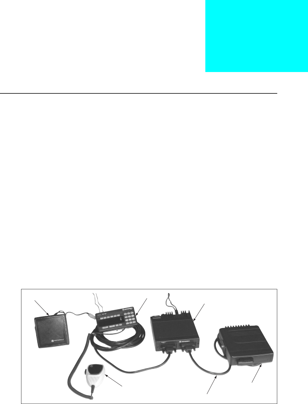
Description The VRS750 Vehicular Repeater System is a mobile radio system
component that provides on-site repeater capability between a
portable radio and a base station (see Figure 1). The VRS gives the
portable user the equivalent range of a mobile radio with the flexibility
of a portable. The VRS is not an ASTRO-capable radio; instead, it is
designed to interface with an ASTRO Spectra® mobile radio. It can only
transmit and receive clear analog transmissions.
The VRS receives transmissions on the portable radio’s transmit
frequency with the proper access PL, and passes these portable signals
to the mobile radio. The mobile radio re-transmits the signals to the
base station on the mobile radio’s transmit frequency.
NOTE: These transmissions have the mobile’s ID, not the
portable’s.
Similarly, base station signals received by the mobile radio are sent to
the VRS and re-transmitted to the portable radio. The VRS does not
provide local repeater capability (received portable signals are not
repeated on the portable receive frequency).
The VRS-to-portable and portable-to-VRS communications are limited
to clear analog only. This is a simplex-only interface; the VRS cannot
receive and transmit simultaneously. The base station-to-mobile and
mobile-to-base communications protocol is not limited to analog
only. Rather, this interface is limited by the features and functions of
the ASTRO Spectra and the base.
Figure 1. VRS750 Vehicular Repeater System
SPEAKER CONTROL HEAD
ASTRO MOBILE
VRS750
HKN6153A
MOBILE
MICROPHONE

2
Ordering
Information
The VRS is a crossband repeater that operates on either UHF or VHF
frequencies. The repeater cannot be operated with a mobile radio
operating in the same band as the VRS unit.
The VRS RF platform is based on a synthesized transceiver. The VRS
supports one channel whose frequency and channel spacing can be
programmed in the field. The VRS remains a simplex repeater and as a
result, the transmit frequency must be set equal to the receive
frequency. The VRS receives its programming information from the
ASTRO Spectra mobile at power-up. The ASTRO Spectra mobile
supports the VRS programming fields via ASTRO Customer
Programming Software (CPS). For more information, refer to “VRS750
Programming,” in Chapter 2, “Installation.”
The VRS is not compatible with ASTRO Spectra mobiles with the
VSELP signaling type.
When integrating a VRS with an ASTRO mobile with a Siren/PA, an
alternate interface cable is needed (HKN6154A). This cable allows the
VRS to be connected to the Siren/PA. For more information, refer to
“Installation,” Chapter 2.
When integrating a VRS with an ASTRO mobile with Dual Control
heads, an alternate interface cable is needed (NKN6460A). This y-cable
allows the VRS to be connected to the ASTRO mobile with two control
heads.
A separate antenna (not included) is necessary for use with the
repeater. Typically, a one-quarter (1/4) wave length antenna
maximizes radiation efficiency when installed at the center of the
vehicle roof. If it is necessary to mount the antenna on the vehicle’s
trunk lid, an appropriate 3 dB gain antenna should be used. See “VRS
Antenna Installation,” in Chapter 2, for details.
A filter for the battery lines (TLN5277B)is available for use with ASTRO
Spectra mobiles. This filter can be used to prevent excessive alternator
whine noise from being heard on the mobile speaker during VRS
operation.
The VRS ships from the factory with the low output power setting at
275 mW and a high output power setting of 2 W. The low output
power setting is the default setting. We recommend the LOW Transmit
Power setting of 275 mW for optimal performance. This output power
provides the VRS with a similar range as the portable when attached
to a mobile antenna. Any deviation from this setting could result in a
loss of communication from the portable to the base.
The Global Tuning Tool (not included) can be used to tune the VRS
output power in the field. For more information refer to “VRS750
Global Tuner,” in Chapter 2.
Contact Customer Resources for information on how to obtain this
Global Tuning Tool.

3
VRS Features The VRS operates with the ASTRO mobile radio and contains the
following integrated features:
•Automatic, multiple-unit, priority-resolution algorithm.
•Portable priority interrupt (PPI) function.
•Conventional/trunked operation.
•Remote switch enable/disable capability for control charger
interface.
•Remote activation of emergency alarm feature.
•In-car monitor operation.
•VRS mobile access tones.
•Mobile radio transmitter steering of up to eight modes via Private-
Line® (PL) code transmission from the portable radio.
•TX PL generator.
•Base repeater operation for two-frequency, simplex, fixed-repeater
systems.
•Mobile audio repeat.
•Compatible with the VRS-EP.
All VRS features can be programmed in the field using ASTRO Spectra
mobile CPS. For more information, refer to “VRS750 Programming,”
in Chapter 2.
IMPORTANT NOTE: All ASTRO Spectra VRS systems with the
same VRS RF transmit/receive frequency
need to be CPS programmed identically
to ensure proper operation. Failure to do
so could result in erratic system operation.
The VRS does not have to be installed in the system for
programming—only the mobile radio is programmed. If the VRS is not
connected after programming the mobile system, an error message
“ERR 12/10” will be displayed on the control head.
Mutually-Exclusive
Features
The VRS IS NOT compatible with the following mobile radio features:
•W3 Control Head is not supported with VRS
•Flush-mounted control heads
•VSELP signaling type
•Data—VRS and data are not compatible on the same channel and
cannot be used simultaneously. VRS should never be activated on
a channel that has packet data enabled, and VRS mode steering
channels should not have packet data enabled.
•Scan
•Over-the-Air Rekeying (OTAR) Rekey Request
4
•Message (from the Control Head)—Trunking or Conventional
•Status (from the Control Head)—Trunking or Conventional
•Emergency Call—Trunking or Conventional—Emergency Call
and VRS are mutually exclusive. Even if the mobile is
programmed for Alarm and Call, when the Alarm case is exited,
the mobile will not transition into Emergency Call while the VRS
is activated. Likewise, if the mobile is in Emergency Call, the VRS
cannot be activated.
NOTE: When an Emergency Alarm is received, the dispatcher
may elevate that talkgroup to Emergency status.
•Reprogram Request—Trunking
•Repeater Access Control—Conventional
•Mobile Single Tone—Conventional
•Seven-Tone Modat—Conventional
•Motorcycle
•Consolette (Digital Remote and Tone Remote)
The following mobile radio features may be received but may not be
initiated or responded to while VRS is enabled.
•Private Conversation™—Trunking
•Call Alert™—Trunking or Conventional
•Telephone Interconnect—Trunking or Conventional
•Voice Selective Call—Conventional
5
Installation 2
When selecting the location for the VRS, make certain that there is
sufficient clearance for routing the antenna cable to the rear of the
unit.
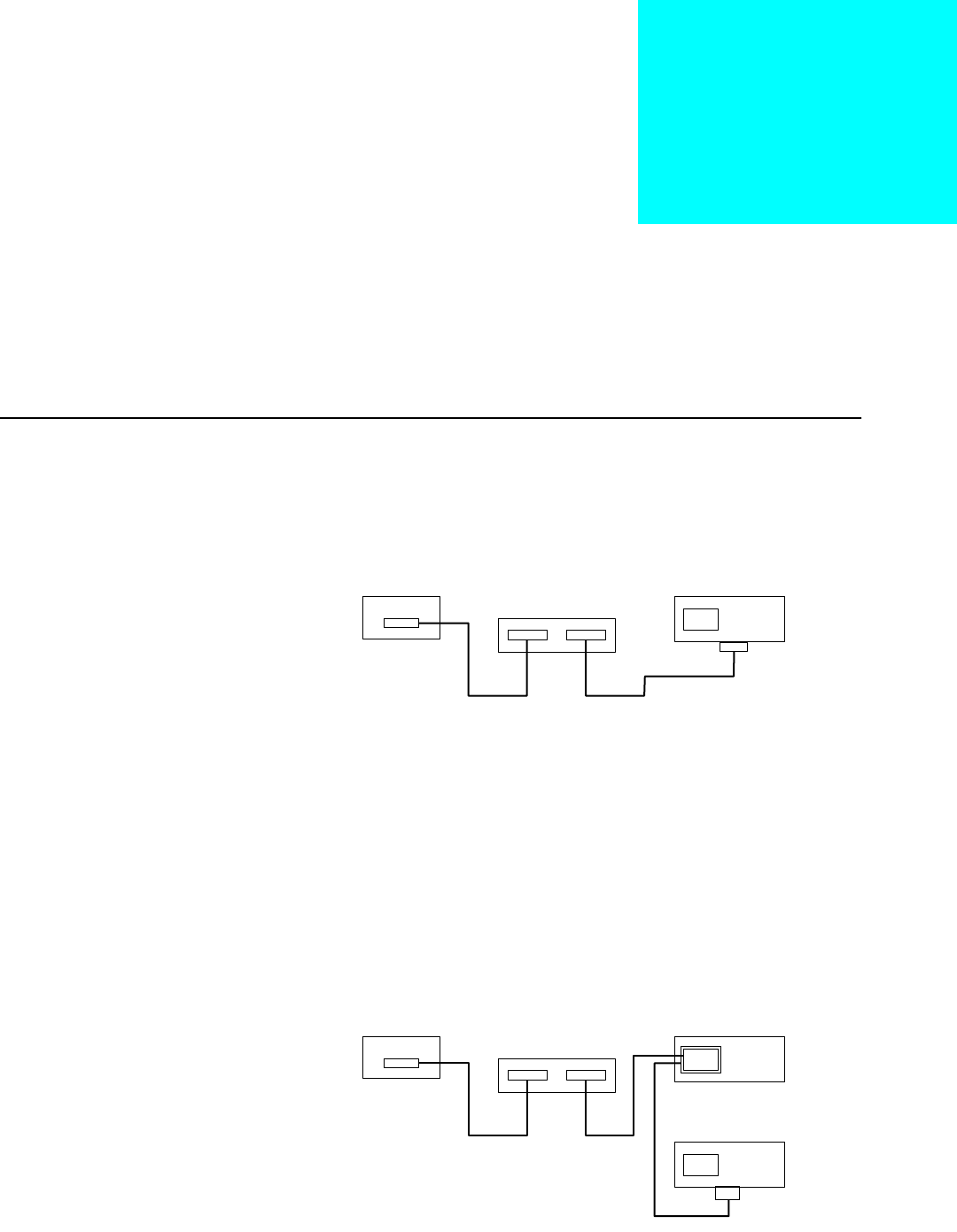
VRS Installation The VRS750 is installed using the HKN6153A interface cable. The
molded DB-25 end connects to the ASTRO mobile front connector.
The DB-25 end with the plastic housing connects to the VRS (see
Figure 2).
If an external Siren/PA is to be used, the G334AC option must be
ordered which replaces the HKN6153A cable with a HKN6154A cable,
or a separate HKN6154A cable must be ordered. To install, plug the “T”
side of the HKN6154A cable to the Siren/PA. Replace the mounting
screw on the HKN4363B cable with the double length screw. Plug this
side into the “T” cable. Plug the DB-25 end of the HKN6154A into the
VRS (see Figure 3).
Figure 2. Installing the VRS to an ASTRO Mobile
Figure 3. Installing the VRS750 with an External Siren/PA
Control Head
ASTRO Mobile
VRS750
HKN6153A
Control Head
ASTRO Mobile
Siren/PA
VRS750
HKN4363B
HKN6154A
6
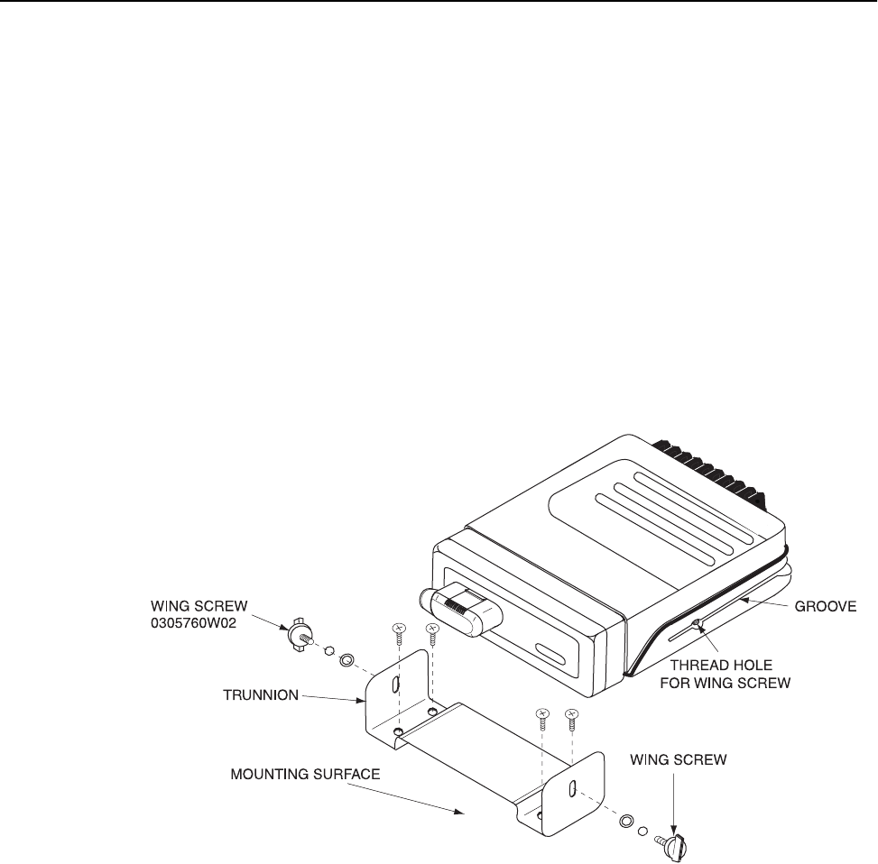
Installation of the
Mounting Trunnion,
HLN6855
1. Select the location to mount your VRS750. The VRS750 must be
mounted within six feet of the mobile radio. Allow sufficient
space around the VRS750 for free air flow for cooling.
2. Using the trunnion mounting bracket as a template, mark the
positions of the holes on the mounting surface.
3. Center-punch the spots you have marked and drill a 4 mm (0.16
inch) hole at each.
4. Secure the trunnion mounting bracket with the four screws
provided (see Figure 4).
5. Connect the VRS-to-Mobile cable to the 25 pin connector on the
bottom of the VRS750.
6. Position the VRS750 in the trunnion.
7. Secure the VRS750 with the two wing screws, and the split and
flat washers provided.
Figure 4. Securing the Trunnion Mounting Bracket
7
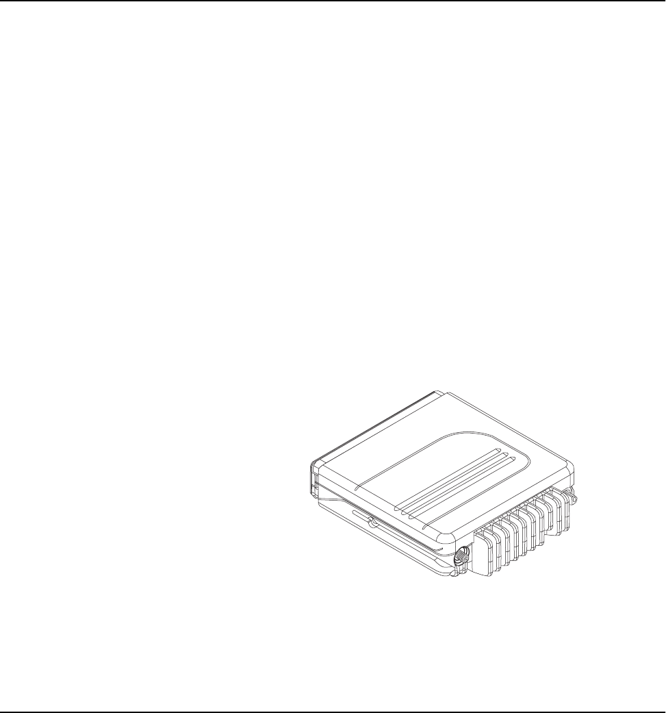
VRS Antenna
Installation
Recommended mobile antenna installations are limited to metal body
vehicles at the center of the roof and center of the trunk deck
locations.
1. Mount the antenna using the instructions provided with the
antenna kit by the manufacturer (an antenna is not included with
the VRS models). Mount the antenna as far from the mobile radio
antenna as possible, never less than three feet. An ideal configuration
would be a roof-mounted mobile radio antenna and a trunk-
mounted VRS antenna.
2. Run the coaxial cable to the VRS750 mounting location. If
necessary, cut off the excess cable and install the cable connector.
3. Connect the antenna cable mini-UHF connector to the antenna
jack on the rear of the VRS750 (see Figure 5). A mini-UHF crimp
connector is provided with each VRS750 unit for easier
installation with a pre-existing antenna. Ensure that the
antenna’s cable connector is fully tightened. An adapter should
NOT be used between the antenna cable mini-UHF connector and
the VRS750.
VRS750
Programming
The user selectable operating parameters for the VRS750 reside in the
ASTRO mobile EEPROM during normal operation. The EEPROM
located in the VRS750 holds the tuning parameters. The VRS750
programming windows reside in ASTRO Spectra CPS and are accessible
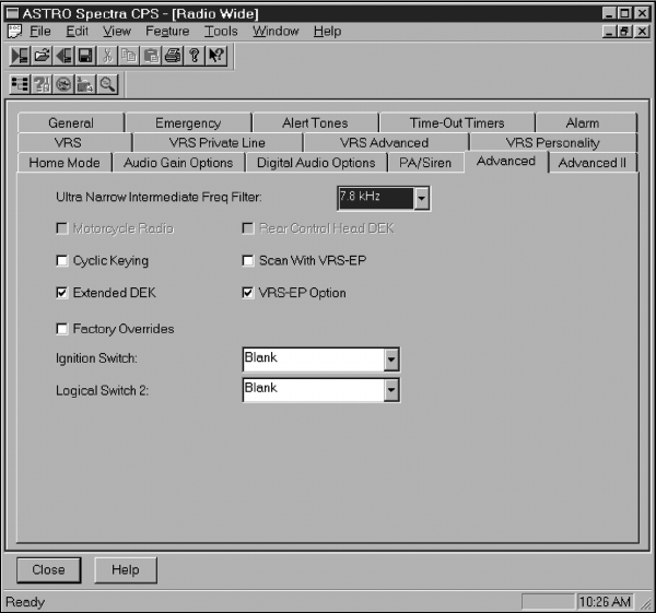
when the “VRS-EP Option” is enabled in CPS under the Radio
Configuration --> Radio Wide --> Advanced Window (see Figure 6).
The VRS750 does not function without CPS programming and is not
pre-programmed at the factory. To ensure operational compatibility
from one unit to the next within the fleet, all of the ASTRO Mobile and
VRS750/VRS-EP systems should be programmed the same way.
Figure 5. Connecting the Antenna Cable
Mini-UHF Connector to the Antenna Jack
ANTENNA
CONNECTOR
8
Special Programming
Notes
The VRS button can be located in any of the indicator button
positions normally used for option buttons.
The VRS750 option can be enabled/disabled by a vehicle interface port
(VIP). Use the VIP Control of VRS box in the Radio Configuration
--> Radio Wide --> VRS window (see Figure 8) to enable VIP control
and to select whether the input control is active open or active closed.
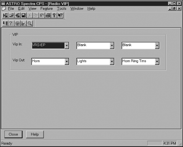
Then use the Radio Configuration --> Radio Wide --> Radio VIP
window (see Figure 7) to select the VIP to be used. However, the VRS
button must still be added to the control unit if it is desired to have
the indicator light when the VRS750 is enabled. See the ASTRO Spectra
CPS user’s manual for details concerning programming the VIP.
NOTE: The ASTRO Spectra CPS user’s manual does not
indicate that the VRS button is required in order to
have the indicator light when the VIP is enabled.
Figure 6. Advanced Window
(Radio Configuration --> Radio Wide --> Advanced)
9
ASTRO VRS
Programming Windows
There are five windows for editing the VRS Option. Four of these
windows are in the Radio Wide section of Radio Configuration while
the fifth window is a table for the VRS mode steering PLs. The first
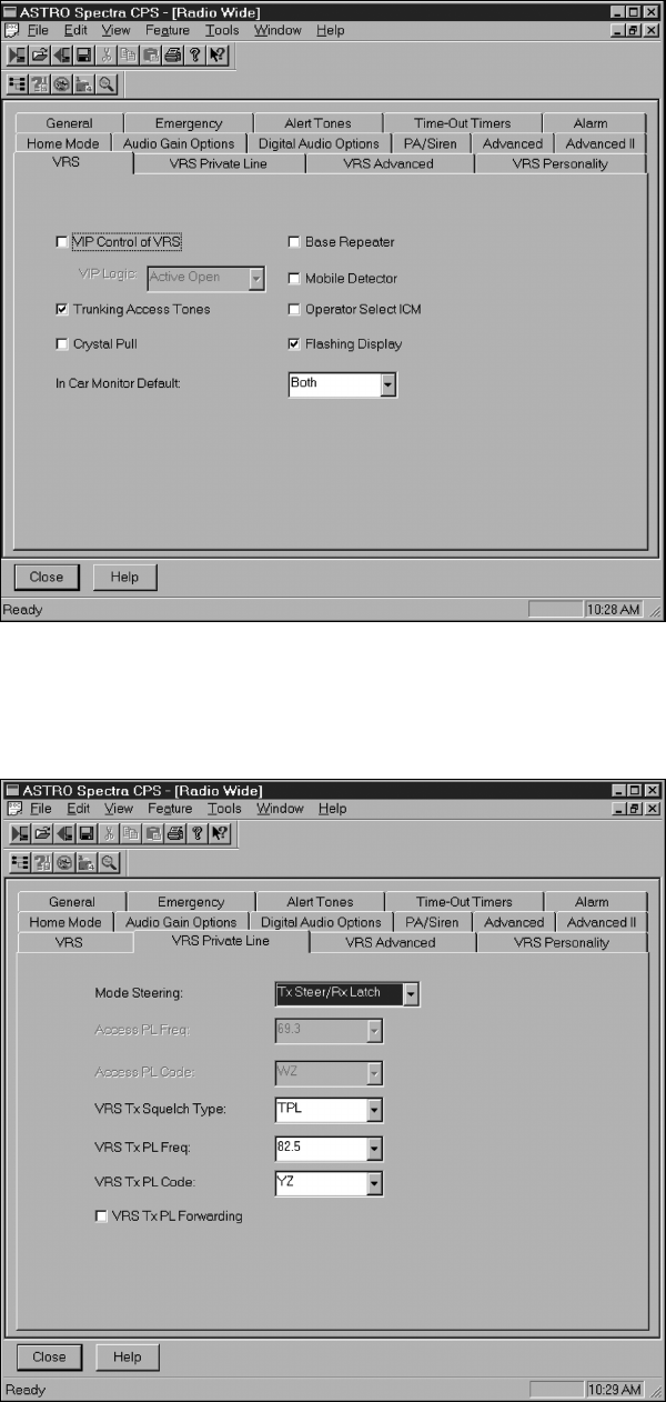
window is the VRS subsection of the Radio Wide options (see Figure
8). In this window Base Repeater, Mobile Detector, Flashing Display,
VIP control of VRS, and Trunking Access Tones can be enabled or
disabled by clicking in the box to the left of the option. This window
is also where the ICM mode can be selected using a pull down menu.
Enabling Base Repeater will add 300 ms of delay to the prioritization
routine to account for fixed repeater attack time.
The second window is the VRS Private Line subsection (see Figure 9).
This window allows the user to select a Mode Steering type, if one is
being used. If Mode Steering is set to Disabled, the Access PL Freq. and
Access PL Code fields will become user selectable. These fields specify
the one PL frequency transmitted by the portable that will be used to
access the VRS750. The VRS750 will treat that access PL in the same
manner as a “select mode” mode steering PL. To edit these fields click
in the Access PL Freq. or Access PL Code box and use the pull down
menu to select the desired frequency or code.
Also located on the second window is the VRS Tx Squelch Type. To edit
this field click in the box to the right and use the pull down menu to
choose between TPL and CSQ. If TPL is selected, meaning that the VRS
should transmit to the portable with PL, the VRS Tx PL Freq. and VRS
Tx PL Code fields will become user selectable. To edit these fields, click
in the VRS Tx PL Freq. or VRS Tx PL Code box and use the pull down
menu to select the desired frequency or code.
Figure 7. Radio VIP Window
(Radio Configuration --> Radio Wide --> Radio VIP)
10
Figure 8. VRS Window
(Radio Configuration --> Radio Wide --> VRS)
Figure 9. VRS Private Line Window
(Radio Configuration --> Radio Wide --> VRS Private Line)
11
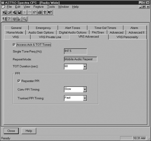
The third window is the VRS Advanced subsection (see Figure 10).
This window is used to enable/disable the Access Acknowledgment
and Time-Out-Timer Tones and Repeater Portable Priority Interrupt
(PPI) as well as selecting the Time-Out-Timer duration. The Time-Out-
Timer duration may be set to 30, 60, or 120 seconds, or infinite. The
infinite setting should be used with caution, since damage to the
transmitter could result from any extremely extended transmission. It
should be noted that the Repeater PPI feature must be enabled to allow
the multi-unit priority algorithm to function correctly when there will
be multiple VRS units on scene. The time between interrupts may be
set to Fast (500 ms) or Slow (2 seconds) for conventional modes and
Fast (500 ms) or Slow (1 second) for trunked modes.
NOTE: When using Rptr PPI, the receiver squelch setting of
the portable must be programmed for CSQ (carrier
squelch).
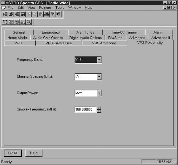
The fourth window is the VRS Personality subsection (see Figure 11).
The VRS Personality sets the VRS Frequency Band, Simplex
Frequency, Channel Spacing, and TX Output Power for the VRS750.
The VRS750 can be programmed for 12.5, 20, or 25 kHz Channel
Spacing with a High or Low output power (factory power settings are
2 W for High and 275 mW for Low). Note that the VRS Personality
will allow the Frequency Band to be set to VHF, UHF R1, or UHF R2
regardless of which model VRS750 is being used, but upon power up
the error message “VRS 001” will be displayed if the frequency band is
incorrect.
Figure 10. VRS Advanced Window
(Radio Configuration --> Radio Wide --> VRS Advanced)
12
NOTE: Older VRS units, such as the VRS-EP, do not support
any of the fields in the VRS Personality window.
However, these fields can be programmed without
having any effect on the VRS-EP, so that the VRS-EP
and VRS750 can be interchangeable without
reprogramming the mobile.
The VRS Personality can be programmed directly into the VRS750
EEPROM using Professional Radio CPS and a new dip switch
configuration, Professional CPS Mode. All other operating parameters
will still be programmed using the ASTRO Spectra CPS. For more
information, refer to “Mode Configuration,” Chapter 6.
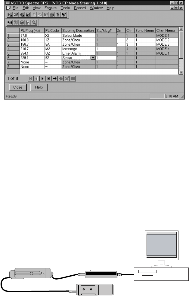
The fifth window, Radio Configuration --> Radio Wide VRS-EP
Mode Steering --> VRS-EP Mode Steering List --> VRS-EP Mode
Steering - 1 (see Figure 12) is a table containing PL and mode steering
information that can be edited. Mode Steering must first be enabled in
the VRS Private Line window before the mode steering PLs in the
table can be edited. To enter the PL codes used in mode steering and
their corresponding destinations, enter the desired PL code or
frequency by using the pull down menu in each PL Freq. or PL Code
box. Then select the corresponding Steering Destination in the same
manner.
If the VRS Tx Squelch Type was set to TPL in the VRS Private Line
window, none of the mode steering PLs may be the same as the VRS
Tx PL Frequency.
Figure 11. VRS Personality Window
(Radio Configuration --> Radio Wide --> VRS Personality)
13
NOTE: The Receive PL filter internal to the VRS is a low pass
filter with a -3 dB point of approximately 170 Hz. As a
result, the PLs greater than 170 Hz will be attenuated
to allow for a decreased decode sensitivity. The higher
the PL frequency the greater the attenuation. The
Emergency, Message, and Status features of the VRS are
best suited for use with these higher PL frequencies.
Due to Host memory considerations, the maximum number of Zones
allowed to be accessed by the VRS Mode Steering window is 20. Any
Zone number greater than 20 will not be allowed in this window but
is allowed for normal radio operation.
VRS750 Global Tuner The Tuner for Professional Radios (Global Tuner) can be used to adjust
the VRS750’s Transmitter Output Power and Receiver Squelch Settings
while in Normal Mode (see Table 6 in Chapter 6). In order to program
the VRS750 using the Global Tuner it should be connected to the
mobile and to a PC via its COM port as indicated in Figure 13.
Figure 12. VRS-EP Mode Steering Window
Figure 13. VRS Connection to the PC
VRS750 SRIB
ASTRO MOBILE
VRS750 TO MOBILE CABLE CONNECT TO THE PCs
COM PORT

14
Once the setup is complete and the mobile is turned on the current
tuning parameters can be read from the VRS750 by selecting File -->
Read Radio Information and Softpots on the Global Tuner.
NOTE: Radio Serial Number and Radio Model Number shown
at the bottom of the screen will not match the model
number and serial number of its associating VRS.
Transmit Power Tuning The VRS750 supports 2 different power levels (High and Low). There
are separate alignments for High and Low power (see Tables 2 and 3).
We recommend setting and using a Low transmit power setting of
275 mW for optimal performance. This output power provides the
VRS750 with a similar range as the portable when attached to a mobile
antenna. Any deviation from this setting could result in a loss of
communication from the portable to the base.
NOTE: Please also note that some countries may have
different restrictions on the power level. If you are not
sure on the power to tune, please check with your
regulatory body. The maximum available power level
given in the table below must not be exceeded.
NOTE: When checking the RF power output of the VRS750,
always use an attenuator pad of at least 30 dB attached
to the radio end of the RF cable. This will avoid an RF
mismatch and ensure a stable RF reading that will not
change with varying lengths of connecting cable.
NOTE: The VRS750 will be programmed from the factory with
a high power setting of ~2 W and a low power setting
of ~275 mW.
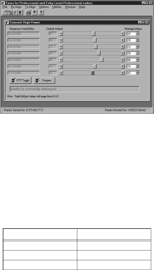
To perform Transmit High Power Tuning, do the following:
1. Under the Tx Align menu, select Transmit Power, then select
High (see Figure 14).
2. Press PTT Toggle. This will key the radio up at F1.
3. Adjust the high power level by moving the slider/spin control or
keying in values in the edit control (press ENTER to confirm
selection after typing in the softpot value).
4. Press PTT Toggle to dekey the radio, go to the next frequency
point by selecting the slider, typing in the edit control box (press
ENTER to confirm selection after typing in the softpot value) or
toggling the softpot value using the spin control.
Table 2. Transmit High Power Level for VRS750s
RF Band (MHz) High Power (W)
VHF (136-174) 5.2-5.7
UHF Band 1 (403-470) 4.2-4.6
UHF Band 2 (450-527) 4.2-4.5
15
5. Press PTT Toggle again to key up the radio at the selected
frequency point.
6. Repeat steps 3-5 for (F2-F7).
7. Press Program to store the softpot values into the radio’s
codeplug.
8. Exit the Transmit High Power function. The mobile will reset
upon exiting
If low power channels are used, perform Transmit Low Power Tuning
as shown in Table 3.
To perform Transmit Low Power Tuning, do the following:
1. Under the Tx Align menu, select Transmit Power, then select
Low.
2. Press PTT Toggle. This will key the radio up at F1.
3. Adjust the power level by moving the slider/spin control or
keying in values in the edit control (press ENTER to confirm
selection after typing in the softpot value).
Figure 14. Transmit High Power Window in the Global Tuner
Table 3. Transmit Low Power Level for VRS750s
RF Band (MHz) Low Power (mW)
VHF (136-174) 240-310
UHF Band 1 (403-470) 240-310
UHF Band 2 (450-527) 240-310

16
4. Press PTT Toggle to dekey the radio, go to the next frequency
point by selecting the slider, typing in the edit control box (press
ENTER to confirm selection) or toggling the softpot value using
the spin control.
5. Press PTT Toggle again to key up the radio at the selected
frequency point.
6. Repeat steps 3-5 for (F2-F7).
7. Press Program to store the softpot values into the radio’s
codeplug.
8. Exit the Transmit Low Power function. The mobile will reset upon
exiting.
Squelch Tuning Under Rx Align, select Squelch Attn. Select either Squelch Attn. 12.5
kHz, Squelch Attn. 20 kHz, or Squelch Attn. 25 kHz Channel
Spacing variations (see Figure 15).
1. Apply an RF signal modulated with 1 kHz tone at 60% rated
deviation (see Table 10 in Chapter 7) for current frequency point
(F1 being the first) of -110 dBm. Make sure that the mobile mic is
off HUB and the VRS is programmed for ICM BOTH mode so that
the audio will be routed to the mobile speaker.
NOTE: The -110 dBm squelch level was chosen so that each
VRS750 would have the same squelch performance as
other VRS750 units as well as VRS-EP units. This
prevents one unit from receiving a signal that the
other cannot.
2. Set softpot to its maximum value to mute the radio. If the VRS750
remains totally unmute at this setting, leave it at the maximum
setting and continue to step 4.
3. Adjust the softpot value by using the slider, keying in the edit box
(press ENTER to confirm selection), or using the spin controls.
Figure 15. Squelch Attenuation Window in the Global Tuner

17
Do this until the radio is totally unmuted. Verify the squelch
closing by inputting a signal level of 4 dB lower (than that of the
-110 dBm level).
4. Repeat steps 1-3 for F2-F7.
5. Press Program to commit the softpot values into the codeplug.
6. Exit the Squelch Attn. function. The mobile will reset upon
exiting.
NOTE: The Auto Tuning feature does not work for the
VRS750.
Table 4 shows the softpot ranges to achieve approximately -110 dBm.
The actual value varies from radio to radio. The VRS transceiver ships
from the factory with the softpot set for -110 dBm. In the event that
this value needs to be re-set in the field, it is recommended that a
communications analyzer or similar piece of test equipment be used to
verify these settings.
Other adjustments can be made using the Global Tuner in the event
that the transceiver is replaced. For more information, refer to
“Transceiver Board Tuning Procedure,” Chapter 7.
When all adjustments have been made, select File --> Program All.
This will program all off the softpot values into the VRS750’s EEPROM.
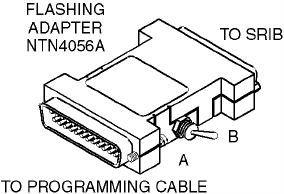
VRS750 Upgrade Kit The VRS750 firmware can be reprogrammed/reflashed using the
VRS750 Upgrade Kit. In order to use the VRS750 Upgrade Kit the
VRS750 should be connected to a desktop or laptop PC via a COM port
as indicated in Figure 13. The Flash adapter (NTN4056A) should be
placed between the VRS750 programming cable (3085031D02) and
the SRIB (see Figure 16). When connecting the VRS750 to the SRIB via
the Flash adapter, make sure that the switch on the adapter is in the
“B” position. With the ASTRO mobile powered on and “PROG VRS”
displayed on the control head, the upgrade can be started. Open the
VRS750 Upgrade Kit and click on the “PROGRAM” button. Follow the
instructions through to the completion of the Flash process. Upon
completion, place the switch on the Flash adapter back in the “B”
position and disconnect the VRS750 from the programming cable. For
more detailed information on the flashing process, consult the “read
me” file for the Upgrade Kit.
Table 4. Softpot Ranges
Band Channel
Spacing (kHz)
Approximate Softpot
Range for -110 dBm
VHF 25 56-63
VHF 12.5 63
UHF R1 25 44-52
UHF R1 12.5 63
UHF R2 25 43-46
UHF R2 12.5 63
18
NOTE: The VRS750 Upgrade Kit will request which baud rate
to use when flashing the first radio. For the VRS750 the
baud rate should not exceed 38,400 bps.
Contact Customer Resources for information on how to obtain this
VRS750 Upgrade Kit.
Figure 16. Flashing Adapter
19
VRS Operation 3
General The VRS is a crossband repeater that repeats either UHF or VHF
portable transmissions though a VHF, UHF, or 800 MHz ASTRO
mobile. The repeater cannot be operated with a mobile radio operating
in the same band as the VRS unit. In multiple-VRS sites, the VRS uses
a priority algorithm to prevent other VRS units from repeating. In this
mode, only the highest priority VRS will serve multiple portable users.
This prevents interference problems associated with multiple VRS
units in proximity to one another.
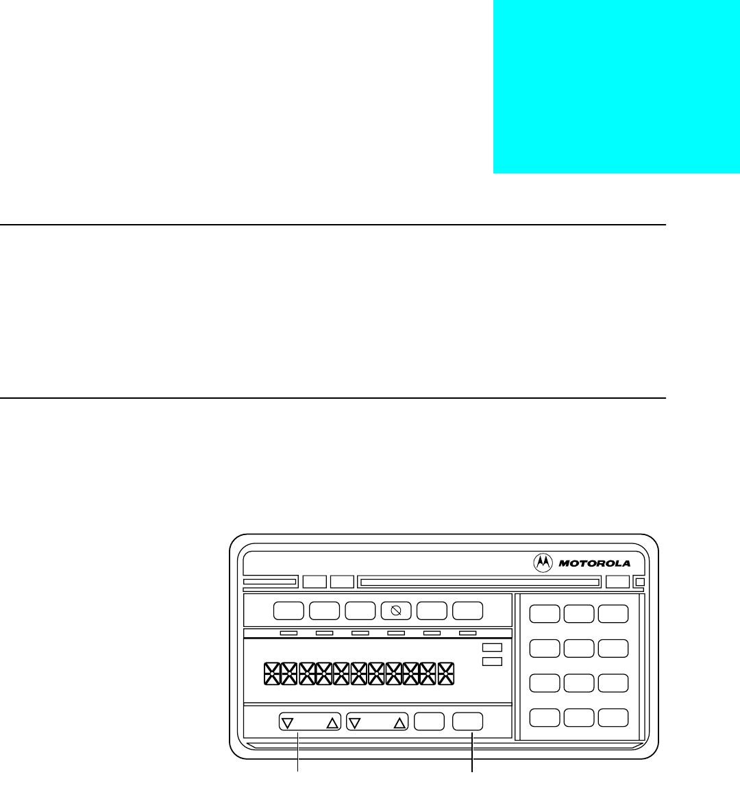
Control Unit The VRS may be enabled/disabled from the ASTRO mobile radio’s
remote-mounted W4, W5, W7, or W9 control head (see Figure 17).
The VRS button may occupy any of the indicator button positions.
Field programming determines the exact position. The VRS requires an
ASTRO radio with a remote-mount control head.
When the VRS is turned on, the indicator illuminates and, after
transmitting the Single Tone burst, the words “VRS BOTH” (indicating
the In-Car Monitor mode) will be displayed momentarily. The
indicator remains on for as long as the VRS is on.
When the VRS unit is activated, it transmits Single Tone on the
portable frequency, and assumes the priority (active) repeater state.
The Single Tone frequency is fixed at 847.5 Hz. For proper operation,
all VRS units to be used in the same system must be programmed with
Figure 17. Typical ASTRO Control Head with VRS
Dir MPL VRS Siren
XMIT BUSY
DIM
Wail Yelp
Hi-Lo
Mon
ExRad
Rcl Sql
Del
Pri
Non
Pri
Mode Vol Sel Home
123
456
789
*0#
MODE ROCKER HOME BUTTON
Astro
PA

20
the same Single Tone frequency, as well as other VRS and ASTRO
mobile features.
Press the VRS button to disable the VRS option. When the system is
turned off and then back on from the control head, the VRS option
returns to the state it was in immediately before the control head was
turned off.
Vehicle Interface
Ports
Another method of enabling/disabling the VRS option is through the
use of a vehicle interface port (VIP). Using ASTRO CPS, the user can
select which VIP to use and whether the input control voltage is to be
high/ground or ground/high.
One use of VIP operation connects the VRS switch lead to a portable
radio vehicular control charger, such as the AVA, SVA, MVA, MTVA, or
ASTRO XTS. Remove the portable from its charger pocket to
automatically enable the VRS option. Replace the portable unit in its
charger to disable the VRS option. A toggle switch on the portable unit
charger allows the portable unit to be removed without enabling the
VRS option.
NOTE: This requires the VIP hardware interface kit,
0180757T61, which is not included with the VRS.
Turning the portable unit charger off, then on does not disable the VRS
option. The VIP setting controls the on/off state of the VRS option. If
the field programmer chooses the VIP option, pressing the VRS button
on the control head will only cause the display to change momentarily
to the In Car Monitor Mode (“VRS BOTH”). It will not enable or
disable the VRS as previously described. It is still necessary, however,
to select in CPS an indicator button for the VRS if it is desired to have
the indicator light when the VRS is enabled.
VRS Access With the VRS on, press the portable radio’s PTT button to begin
transmissions. The VRS programming must include correct PL
frequencies to allow the portable unit to access the option. The VRS
option receives signals with the correct PL, then uses the mobile radio
to re-transmit the signals. The control head’s XMIT indicator lights
during the re-transmission.
The VRS re-transmits received mobile signals as explained in the
“Mobile Audio Repeat” paragraph on page 21. Note that the XMIT
indicator does not light when the VRS is transmitting to the portable.
To transmit directly to the other portable units, turn off the portable
transmit PL. This allows you to talk around the VRS without
transmitting on the mobile channels.
In-Car Monitor The “In-Car Monitor” (ICM) feature is for use in a two-man operation
where one user (user 1) is out of the vehicle while the other (user 2)
remains in the vehicle. This allows user 2 limited access to both mobile
and portable communications when the VRS is on, even when the
repeater is the priority unit. ICM operation is set to BOTH.

21
ICM Transmissions VRS BASE:
Press the mobile’s PTT to transmit on the frequency corresponding to
the mode shown on the control head’s display. If this mobile’s VRS is
the priority unit (in delay state zero), the VRS unit will then become
non-priority upon the mobile PTT. If you press the mobile’s PTT during
portable-to-base VRS activity, a talk-prohibit tone sounds and the mic
audio is disabled.
VRS BOTH:
Press the mobile’s PTT to transmit simultaneously on the frequency
corresponding to the mode shown on the control head’s display, and
the portable frequency. Use the ASTRO CPS to enable the VRS TX PL
generator option to transmit with the proper PL frequency. If you press
the mobile’s PTT during portable-to-base VRS activity, a momentary
talk-prohibit tone sounds and the microphone audio is disabled.
When using VRS BASE or VRS BOTH mode, all mobile transmissions
are on the mode that is shown on the control head’s display. If the VRS
is currently steering to another mode, that steered mode will be
displayed on the control head. Any mobile transmissions will be on
that new mode until the portable steers the VRS back or the mode
rocker switch is used to change modes. If the mode rocker switch is
used to change modes, the portable user will not be made aware of this
mode change. With Ack Tones are enabled, the portable user will hear
a “bad” tone if the mode is changed during the transmission.
VRS Reception The VRS option has no effect on mobile radio squelch control or
normal mobile radio reception. The VRS portable unit’s squelch
setting is not user adjustable. Portable audio is heard from the mobile
speaker of the priority VRS unit as shown in Table 5.
Repeated portable transmissions will always be heard from the mobile
speakers.
Portable transmissions without proper PL will only be heard from the
mobile speaker if the microphone is off HUB.
Mobile Audio
Repeat
The VRS transmits to the portable when audio unmutes the mobile
speaker. This allows the user to set the monitor button “on” to defeat
the coded squelch requirements of the mobile radio on a base-to-
portable transmission or “off” to prevent the VRS from repeating
base-to-portable (HUB will also disable this), unless the coded squelch
requirements of the mobile radio are met. Button presses (that is,
Volume, Mode, etc.) on the priority mobile unit will also be
transmitted by the VRS.
Table 5. Portable Audio Heard from Mobile Speaker
Mobile
Microphone
Portable Audio Heard
from Mobile Speaker
On HUB PL*
Off HUB CSQ
* = any valid repeater access PL

22
Notes

23
Operation of VRS
Options
4
The following sections describe the operation of CPS field-
programmable options of the VRS. This includes information about
when to use an option and compatibility between options.
Base Repeater
For two-frequency simplex systems using a fixed-site repeater, you can
enable the base repeater option. This adds 300 ms of delay to the
prioritization routine to account for the fixed repeater attack time.
This allows non-priority mobiles to detect any priority mobile in the
system through the base repeater.
Mobile Detector
The Mobile Detector feature allows the user to operate VRS units with
two-frequency simplex dispatch systems without a base repeater. This
feature allows the automatic multi-unit priority resolution algorithm
to function in the above scenario. When this feature is activated by the
CPS, a non-priority VRS will send a message to the mobile to enable a
“Listen Around” feature when a proper portable PL is received.
“Listen Around” switches the mobile radio’s receive frequency to
match that of its transmit frequency of the steered mode. The non-
priority VRS will count down in priority if its corresponding mobile
does not detect the repeated transmission on the “Listen Around”
frequency. When the portable is dekeyed, the non-priority VRS will
send a second message to the mobile to disable “Listen Around” and
return to normal operation. This feature does not use any additional
user modes in the mobile.
NOTE:
The Mobile Detector feature only works on
conventional modes. Trunked modes will be
unaffected.
VRS Transmit PL
Generator
The transmit PL generator, when enabled, causes the VRS to transmit
(base-to-portable), with specific field programmable PL tones. The
selected VRS transmit PL frequency cannot be the same as any of the
VRS receive PL frequencies that the portable uses to access the
vehicular repeater.
VRS Mode Steering
The VRS steering option gives the portable operator the ability to select
the current mobile radio mode via PL tones. The total number of
Mode-Steered modes can not exceed eight (including emergency,
message, and status). The operator may program as many as eight such
tones, along with corresponding mobile mode numbers, into the VRS.
24
The portable operator sets the channel or mode select switch to the
position corresponding to the desired mobile mode and keys up the
portable. The VRS unit decodes the PL tone and steers the mobile radio
to the desired mode. There are two types of steering supported:
Transmitter Steering/Receiver Latching, and Transmitter Steering/
Receiver Steering.
NOTE:
If mode steering is not selected during CPS
programming, the programmer will need to enter the
repeater access PL, which corresponds to a single access
PL with select mode steering.
Steering Types
•
<Transmitter Steering/Receiver Latching>—On portable-to-base
repeating, the mobile radio is steered to the proper mode as
determined by the received PL from the portable. When the
portable dekeys, the condition to repeat ceases, and the mobile
radio remains on this mode. Thus, all future base-to-portable
repeating is heard via the mobile mode last steered by the
portable.
The mobile control head will display the steered/latched mode. If,
sometime after this operation and while no repeat is occurring,
the ICM user keys the mobile with the microphone’s PTT button,
the mobile will now transmit on the latched mode that is
displayed on the control head. If, however, the in-car-monitor
(ICM) user changes the selected mode using the mobile’s mode
rocker switch before pressing the mic PTT, the mobile will now
transmit on the new selected mode.
NOTE:
For the above type of steering, the portable user will be
able to steer back to the selected user mode on the
control head by programming one PL destination for
Sel-Mode. However, the selected mode can be changed
by the rocker mode switch.
•
<Transmitter Steering/Receiver Steering>—On portable-to-base
repeating, the mobile radio is steered to the proper mode as
determined by the received PL from the portable. When the
portable dekeys, the condition to repeat ceases, and the mobile
radio remains on this mode for 6 seconds. During this 6 seconds,
the VRS waits for a repeatable base-to-portable transmission to be
received.
• If a base-to-portable transmission is not received, the mobile
will return to the last mode selected by the control head’s
rocker switch (current user-selected mode).
• If a base-to-portable transmission is received during the 6-
second timer, the timer will be reset back to 6 seconds and
start over at the end of the transmission.
• If the portable is keyed during the 6 seconds, the VRS will
handle the destination PL accordingly and reset the timer. If
the 6-second timer has not expired, no repeat is occurring,
and the ICM user keys the mobile with a microphone PTT, the
mobile will transmit on the steered mode and the 6-second
timer will start over at the end of the transmission.
25
Steering Destination
Types
There are five types of actions, or “steering destination types,” that the
VRS can be programmed to perform as a result of receiving a portable
transmission with the specified PL:
NOTE: Each receive PL can only be used once and can only be
programmed with one type of steering destination (for
example, a single PL cannot be programmed to both
change the mobile mode and send a message.)
Zone/Chan The VRS will command the ASTRO mobile to change to the mode
programmed by the CPS. Once the mobile has steered, it will follow
the conventions of the type of steering selected (for example,
Transmitter Steering/Receiver Latching).
Select Mode The VRS will command the ASTRO mobile to return to the last mode
selected by the rocker switch on the control head. If the portable user
has steered to another mode, and the selected mode is changed in the
car, the steering will be canceled until the VRS receives another mode
steering PL.
Emergency Alarm The VRS will initiate an Emergency Alarm through the ASTRO mobile,
if the mobile is programmed for this type of Emergency, in the same
manner as if the Emergency button on the control head were pressed.
The type of Emergency (trunked or conventional) depends on the
currently selected mobile mode, (trunked or conventional,
respectively).
The VRS will only generate an Emergency, not perform a portable-to-
base audio repeat, while the portable is transmitting on an
“Emergency request” channel. This feature is typically implemented
in the portable, using a one-touch button that has been programmed
for Emergency-revert to a channel with the proper PL.
Although the portable generates MDC tones, the VRS cannot decode
MDC. Instead it responds to the PL of the portable mode on which the
Emergency MDC tones are transmitted. All of this is transparent to the
user.
Message The VRS will command the ASTRO mobile to send out a CPS-
programmed message on the mode currently displayed on the control
head, in the same manner as if the request to send a message had been
generated using the control head. The VRS will send out only one
message per received portable signal. No mode steering will occur; the
currently steered/latched mode and the selected mobile mode will
remain as they were before the request to send a message was received.
If the message selected is valid, the VRS will transmit to the portable
the mobile tones indicating whether or not the valid message was
acknowledged. If the message selected is invalid, (either incorrectly
programmed in CPS or not a valid message for the currently displayed
mode), the VRS will send a low-pitched alarm tone to the portable.
To generate a message request, the portable user would:
•select the channel on the portable programmed for the message
request,

26
•momentarily press the PTT button,
•wait for the confirmation tone, and
•return the channel selector to a voice channel.
The VRS will not perform a portable-to-base audio repeat while the
portable is transmitting on a “message request” channel.
NOTE: A message cannot be generated from the control head
while the VRS is activated.
Status The VRS will command the ASTRO mobile to send out a CPS-
programmed status on the mode currently displayed on the control
head, in the same manner as if the request to send status had been
generated using the control head. The VRS will send out only one
status per received portable signal. No mode steering will occur; the
currently steered/latched mode and the selected mobile mode will
remain as they were before the request to send a status was received.
If the status selected is valid, the VRS will transmit to the portable the
mobile tones indicating whether or not the valid status was
acknowledged. If the status selected is invalid, (either incorrectly
programmed in CPS or not a valid status for the currently displayed
mode), the VRS will send a low-pitched alarm tone to the portable.
To generate a status request, the portable user would:
•select the channel on the portable programmed for the status
request,
•momentarily press the PTT button,
•wait for the confirmation tone, and
•return the channel selector to a voice channel.
The VRS will not perform a portable-to-base audio repeat while the
portable is transmitting on a “status request” channel.
NOTE: A status cannot be generated from the control head
while the VRS is activated.
Time-Out Timer The Time-out Timer (TOT) duration value sets the maximum allowable
time for a base-to-portable transmission. The VRS TOT may be set to
30, 60, 120 seconds, or disabled. When a unit times out, it counts up
to delay state one. This removes it as the priority unit.
VRS Single Tone When the VRS unit is enabled, it transmits an audible tone (Single
Tone) for 700 mS which is used by other VRS units for the automatic
prioritization routine. The Single Tone frequency is fixed at 847.5 Hz.

27
VRS Mobile-TX
Acknowledgment
Tones
(Conventional Only)
When this option is enabled, the VRS transmits a 750 Hz feedback
tone after it has received a repeatable message on the portable
frequency. This signals the portable operator that the transmission was
received. If the repeated message was cut short due to the mobile TOT
being exceeded or the mobile channel being changed during the
repeat, a lower-pitched tone (304 Hz) sounds. If the portable user does
not hear a tone after completing a transmission, the portable is either
out of range of the repeater or there is no priority repeater in the area.
See “VRS Mobile Trunking Tones (Trunking Only)” on page 38 for a
description of trunking acknowledgment tones.
Flashing Display The Flashing Display feature causes the display on the control head to
alternate between the current mode and “VRS BOTH.” This feature is
used primarily when the VRS enable/disable button does not have an
indicator light or when VIP activation is used. This feature is normally
disabled in CPS. The length of time “VRS BOTH” is displayed every
6 seconds is determined by the “temporary message display timer”
value. This value (from 250 to 6250 ms [default = 1000 ms]) can
be programmed by the CPS. To configure, select Radio Configuration
--> Display & Menu --> Advanced screen.
Repeater PPI The Repeater Portable Priority Interrupt (PPI), when enabled, causes a
base-to-portable transmission to be interrupted every 1 second in
trunked mode or 2 seconds in conventional mode so that the repeater
can search for a portable radio signal. (These times are programmable
and may be changed to 500 ms for trunked or 500 ms for conventional
modes). This interruption may be heard on the portable as a “clicking”
noise, but PPI is necessary to give the portable user priority over base-
to-portable transmissions, for the self-clearing function of the
automatic priority resolution feature, and to allow portable users in
trunked mode to break in during system hang time to prevent loss of
voice channel. This feature may be disabled through CPS.
Quick-Key This feature allows the portable user to determine the status of the
mobile trunking system. The feature is initiated by a short press of the
portable’s PTT that is long enough for the VRS to key the mobile and
access the trunking system, for less than 1 second in duration.

28
Notes

29
Detailed VRS Operation 5
Multi-VRS
Operation
The VRS is designed to accommodate multiple VRS units in the same
area. This is accomplished by each VRS maintaining a priority level or
delay state. During either portable-to-base or base-to-portable
transmissions, only the highest priority VRS will transmit or cause a
mobile PTT. The procedures for determining priority levels in multi-
VRS operation are discussed next.
Determining Priority
Levels
Whenever a VRS is enabled, it transmits a Single Tone burst (except if
portable activity is already present). The Single Tone burst frequency is
fixed at 847.5 Hz. By default, when a VRS (VRS number 1) unit is
enabled, it becomes the priority unit with a delay state of zero. When
a second VRS unit (VRS number 2) is enabled in the area, it will
transmit a Single Tone burst as described. Upon receiving this signal,
VRS number 1 will know that another VRS is active and change its
priority to delay state one from delay state zero. If a third VRS were to
be enabled, VRS number 1 would change to delay state two and VRS
number 2 would change to delay state one. This process could
continue up until delay state seven is reached by VRS number 1,
meaning that eight VRS units have been enabled. After eight VRS units
are activated, they begin to stack up at delay state seven.
Portable-to-Base
Transmissions
If a portable begins to transmit, only the highest priority VRS will PTT
its corresponding mobile for transmission to the base. The other VRS
units, however, will be able to hear the portable transmission and
monitor for mobile channel activity. Channel activity is verified by a
squelch detect of the mobile. For non-priority units, the portable’s
audio will be sent to the mobile’s speaker (unmuted) from the VRS, not
from the mobile. This allows the mobile to monitor the correct
transmit frequency. If mode steering options are enabled then the
non-priority VRS units monitor their mobile’s channel activity on the
channel steered to by the portable’s PL and not on the mobile’s current
user selected channel.
The non-priority VRS units have a short delay in which they expect to
see the squelch detect message. Conventional system units will wait at
least 600 ms and trunking system units will wait at least 1500 ms. This
time period is referred to as one delay state. If in the appropriate time
frame a squelch detect message is not received, the priority VRS unit is
assumed to have been disabled and all other VRS units will increase
one priority level (for example, go from delay state 2 to delay state 1).
The VRS units will continue to count down until a squelch detect
message is received. In an extreme case, in which all but the lowest
priority VRS units are disabled, it is possible that the remaining VRS
unit which was the lowest priority (highest delay state) will have to
wait up to 7 delay states before transmitting. This can lead to a
transmission delay of up to 10.5 seconds for a trunking unit.
30
On conventional modes if the VRS <Base Repeater> option is enabled
via CPS, then an additional 300 ms time delay is added to the delay
states. This allows time for the mobile radios to transmit to and receive
from a repeater site.
Base-to-Portable
Transmissions
When a base transmits, only the priority VRS unit will transmit to the
portable. The other VRS units monitor activity on the portable
channel. Similar to the previous case, if portable activity is not
detected in the specified time frame after receiving mobile channel
activity, the non-priority VRS units will decrease one delay state, until
eventually one unit is in priority.
During base-to-portable transmissions, the delay state timing is
slightly different from that encountered during portable-to-base
transmissions. On conventional modes, the first delay state is
1 second; on trunking modes, the first delay state is 3.4 seconds. All
other delay states, on either trunking or conventional modes, are
400 mS. The worst-case delay for a unit to count into priority during a
base-to-portable transmission in a trunking system would, therefore,
be 5.8 seconds.
See the description of the Portable Priority Interrupt feature on
page 34 for information on the self-clearing feature used to re-
establish a single priority unit when multiple units are mistakenly in
priority. This condition may occur when a VRS unit is activated before
arriving on a scene, or in the unlikely case where several units stack up
at delay state seven and all higher priority units (those in delay states
one through six) leave the scene first or are otherwise disabled.
Single Unit Operation Normal radio communication between a VRS-equipped vehicle (unit
A) and the base is via the mobile radio. When the operator decides to
leave the vehicle and use the VRS option, simply press the VRS button
or remove the portable from the charger if VIP operation is enabled to
turn on the vehicle’s repeater. The repeater transmits the Single Tone
burst on the associated portable radio frequency and sets the delay
state to zero. When the delay state is zero, this unit is the priority unit.
See Figure 18.
IMPORTANT NOTE: The VRS is designed to be a stationary
repeater system. The VRS unit should
always be disabled when the vehicle is
moving. FAILURE TO DO SO COULD
RESULT IN ERRATIC SYSTEM
OPERATION.
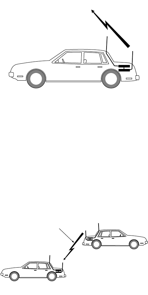
31
Two-Unit Operation The arrival of another VRS-equipped vehicle (unit B) into the coverage
area of unit A has no effect on unit A’s radio operation until unit B’s
VRS is enabled.
Unless there are portable transmissions occurring when unit B arrives,
unit B’s repeater transmits a Single Tone burst when its VRS option is
turned on. Unit B’s repeater priority counter initializes in delay state
zero, making unit B the priority unit. Unit A’s repeater/portable
receives unit B’s Single Tone transmission, which sets unit A’s repeater
to delay state one. See Figure 19. Transmissions from portable units in
the area now repeat through unit B. See Figure 20.
A portable radio’s transmissions (solid arrows in Figure 20) go to all
portable radios and VRSs in the area. Because unit B is the priority
repeater, it repeats the portable’s signal (open arrows in Figure 20) to
the base station and other mobile radios.
Unit A cannot countdown and repeat until the delay state one time
delay elapses. However, because unit A detects the mobile carrier of the
priority unit (open arrow in Figure 20) before the delay expires, the
priority counter does not begin the countdown. Unit A remains in
delay state one and does not repeat portable transmissions.
Figure 18. Single VRS Unit Operation
SINGLE TONE
BURST
UNIT A
“DELAY STATE ZERO”
PRIORITY UNIT
MAEPF-26079-O
Figure 19. Two-Unit VRS Operation
SINGLE TONE
BURST
UNIT A
“DELAY STATE ONE”
UNIT B
“DELAY STATE ZERO”
PRIORITY UNIT
MAEPF-26080-O
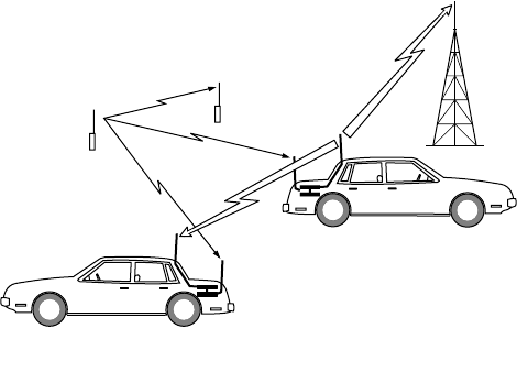
32
If unit B activates its VRS during portable transmissions, unit B does
NOT transmit Single Tone or enable in delay state zero. Unit B must
wait until it cannot detect the portable signal before transmitting
Singletone and taking over as the priority unit as described above.
Three-Unit Operation Should another VRS-equipped vehicle (unit C) come into the area, the
same sequence of events occurs as previously described in the “Two-
Unit Operation” section on page 31. Unit C’s arrival has no effect on
unit A’s or B’s radio operation until unit C’s VRS is enabled.
Unless there are portable transmissions occurring when unit C arrives,
unit C’s repeater transmits a Single Tone burst when its VRS option is
turned on. Unit C’s repeater priority counter initializes in delay state
zero, making unit C the priority unit. Unit A’s repeater/portable
receives unit C’s transmission which sets unit A’s repeater to delay state
two. Unit B’s repeater/portable receives unit C’s transmission which
sets unit B’s repeater to delay state one. Transmissions from portable
units in the area now repeat through unit C. All lower-priority units
will receive incoming portable transmissions, but will not key up their
mobiles because they are in a delay state. See Figure 21.
Figure 20. Two-Unit VRS Transmissions
UNIT A
“DELAY STATE ONE”
UNIT B
“DELAY STATE ZERO”
PRIORITY UNIT
MAEPF-26081-O
TRANSMITS TO
BASE STATION AND
MOBILE RADIOS
IN AREA
TRANSMITS TO
ALL REPEATERS AND
PORTABLE RADIOS
IN THE AREA
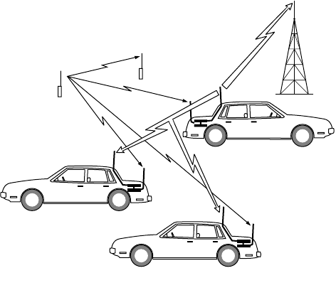
33
Departure of a VRS Unit The priority unit may change, depending upon the order in which
they leave, as vehicles leave the coverage area. For example, in Figure
21, when unit A turns the VRS option off, it has no effect on the
priority unit (unit C). Unit C continues to be the priority unit and
repeat transmissions.
When the priority unit (unit C) turns the VRS option off and
conditions for repeater transmissions occur, the unit in delay state one
(unit B in Figure 21) counts down to delay state zero and becomes the
priority unit. See Figure 22.
IMPORTANT NOTE: Non-priority units (those in delay state 1
or higher) will not count down into
priority if the portable user attempts to
send a status or message. If there is no
priority unit on scene, the request will be
ignored.
Figure 21. Three VRS Unit Transmission Sequence
UNIT B
“DELAY STATE ONE”
UNIT A
“DELAY STATE TWO”
UNIT C
“DELAY STATE ZERO”
PRIORITY UNIT
MAEPF-26082 -O
TRANSMITS TO
BASE STATION AND
MOBILE RADIOS
IN AREA
TRANSMITS TO
ALL REPEATERS AND
PORTABLE RADIOS
IN THE AREA
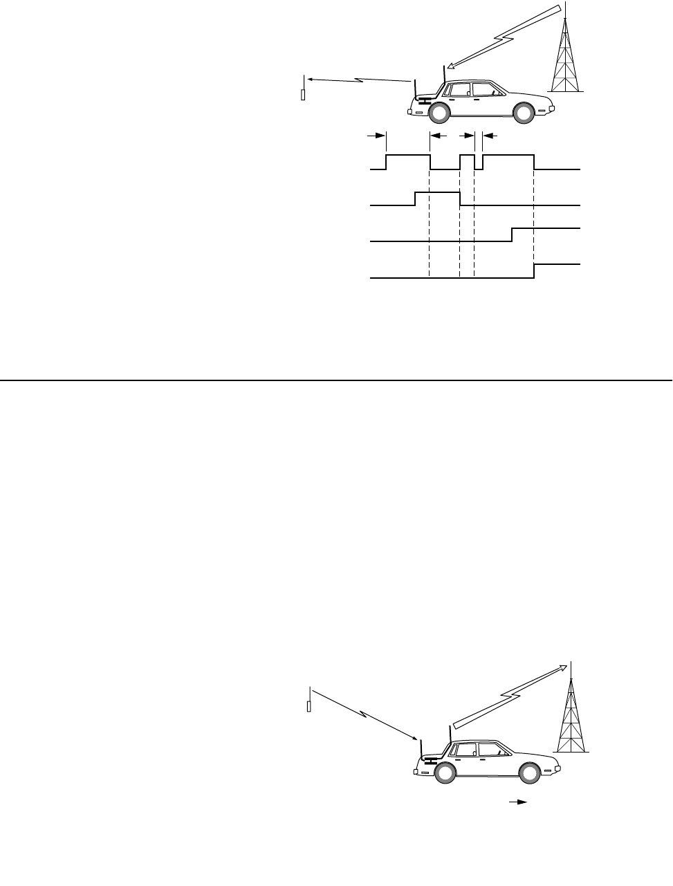
34
Rptr PPI—Portable
Priority Interrupt
NOTE: When using Rptr PPI, the receiver squelch setting of
the portable must be programmed for CSQ (carrier
squelch).
<Rptr PPI> is CPS programmable. The main function of <Rptr PPI> is
to allow the portable to interrupt base-to-portable transmissions.
During VRS to portable transmissions, an interrupt is sent to the
transmitter every 2 seconds on conventional modes and 1 second on
trunking modes. (These times are CPS programmable and may be
changed to 500 ms for trunked modes or 500 ms for conventional
modes.) There is also a random time factor added to the base interval
to prevent two VRS units from interrupting at the same time. This
interrupt allows the receiver to monitor portable or other VRS activity
for approximately 6 ms. See the timing chart in Figure 23.
Figure 22. Priority Unit Reassignment
MAEPF-26083-O
VRS REPEATER
TRANSMITTER
PORTABLE
TRANSMITTER
WITHOUT “PL”
PORTABLE
TRANSMITTER
WITH “PL”
MOBILE
TRANSMITTER
ON
OFF
ON
OFF
ON
OFF
ON
OFF
~ 2 sec ~ 6 msec
Figure 23. Portable Priority Interrupt
UNIT B
DELAY UNITS 1 0
MAEPF-26084-O
REPEATER WAITS ONE DELAY UNIT, COUNTS DOWN (1,0),
AND BECOMES PRIORITY UNIT.
THE PRIORITY STATE COUNTER IN OTHER REPEATERS
ALSO COUNTS DOWN BY ONE DELAY UNIT.
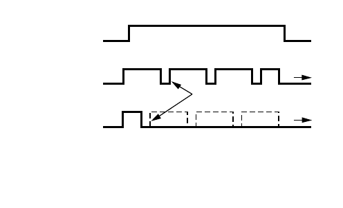
35
If a portable’s signal without PL tone is present when the repeater is
interrupted, the repeater transmitter remains inhibited for the
duration of the incoming signal. If the portable’s signal is modulated
with a PL signal, the priority unit repeats the message back to the base
station on top of the incoming signal.
In addition to giving the portable user priority over all incoming
signals, the Portable Priority Interrupt is used for three basic functions:
1. Self-Clearing—This is used when two or more priority VRS units
are on the same scene. On the first base-to-portable transmission,
all priority VRS units will start to transmit. The first one to have
an interrupt and detect carrier without proper portable PL
(meaning another VRS is transmitting) will count up to priority
state one, a condition which is referred to as self clearing. This
will continue to happen until only one priority VRS is on scene.
As an example, consider a case in which both units A and B are in
the priority state (delay state zero). When conditions for repeater
transmitting begin (i.e., the mobile receives a base signal), both
VRS units begin transmitting. Figure 24 shows the unit B
interrupt pulse occurring first (due to the random time factor
added to the interrupt interval). When unit B is interrupted, it
detects another VRS unit transmitting and so unit B’s transmitter
remains inhibited. Unit B is set to delay state one and unit A
remains the priority unit since by the time unit A’s transmitter is
interrupted, unit B is no longer transmitting.
2. Repeater Hangtime—This allows the user to get back into a
conventional repeater or trunked system during hangtime. The
timing is faster for trunked systems due to the added feature of
talk permit tones being passed to the portable. If the portable keys
up with proper PL, then the VRS will key up the mobile. If proper
PL is not sent, the VRS will assume another VRS is in the area and
count itself out of priority.
Figure 24. Self-Clearing Timing Diagram
TWO UNITS IN PRIORITY STATE
MOBILE RADIOS A & B
RECEIVE MESSAGE
REPEATER A
TRANSMITS
REPEATER B
TRANSMITS
REPEATER A WAS NOT INTERRUPTED AND REMAINS
THE PRIORITY UNIT.
REPEATER B WAS INTERRUPTED BY ANOTHER REPEATER,
THEREFORE DELAY IS INCREMENTED BY ONE UNIT.
MAEPF-26085-O
INTERRUPT
PULSE DELAY STATE
DELAY STATE
0 0
0 1

36
NOTE: If Repeater PPI is disabled on an analog trunking
system with transmission trunking enabled, the Quick
Key feature becomes useless, since the user will be
unable to break-in during the repeater hangtime after
the channel is acquired. For this reason, repeater PPI
should always be ENABLED on an analog trunking
system.
3. Emergency—This allows the portable to have priority over
dispatch.
A drawback of portable priority interrupt is that during all base-
to-portable transmissions, the signal drops out for approximately
6-8 ms every: 2 seconds (conventional); or 1 second (trunking) if
the “slow” PPI option is chosen; or every 500 ms (either trunking
or conventional if the “fast” option is chosen in CPS).
The repeater PPI function may be used by the portable user in the
following manner:
During a base-to-portable transmission, the portable user wants to
interrupt and transmit to the base.
• Portable must transmit with the VRS correct access or steering
PL.
• When the VRS transmitter is interrupted, the VRS will detect
channel activity from the portable’s transmission and switch
to receive mode.
• The VRS will then transmit VRS TX Audio to the base.
• The VRS RX Audio is routed to the mobile speaker.
TX PL Self-Clearing As part of the multi-unit resolution prioritization algorithm, TX PL
Self-Clearing operates by adding the VRS transmit PL to the list of PLs
that the VRS monitors. If a VRS transmit PL is detected by a priority
VRS (delay state 0), it will indicate that another VRS is transmitting.
This feature will cause the original priority VRS to count up to delay
state 1, 2, or 3, and allow the transmitting VRS to remain in priority.
The delay state is randomized to prevent multiple units from stacking
up in delay state 1. In order to prevent ICM transmissions from other
VRS units affecting the priority states, the TX PL Self-Clearing feature
only works when detecting TX PL from a VRS that is repeating a Base-
To-Portable transmission. This function is not programmable, but has
no effect unless TX PL is used. This feature will not operate properly
unless all VRS units are programmed to transmit with the same
frequency PL, and the receiver squelch of the VRS750 units is set to
approximately -110 dBm.
NOTE: The VRS750 ships from the factory with a receiver
squelch setting of approximately -110 dBm. If the
VRS750 is not going to be programmed with a TX PL,
then the Global Tuner can be used to loosen the
receiver squelch for better radio performance.

37
ICM Functions The in-car-monitor (ICM) allows limited use of the mobile while the
VRS is enabled.
<ICM Base> Mode
In this mode pressing the mobile’s PTT will cause the mobile to
transmit on the mode shown on the control head display. The VRS will
not transmit the mic audio to the portable. During portable-to-base
repeat operations pressing the mobile’s PTT will result in the talk
prohibit tone sounding momentarily and the mic audio will not be
transmitted to the portable. When the mic is on HUB portable
transmissions will not be heard at the mobile’s speaker. When the mic
is off HUB only portable transmissions with the proper PL will unmute
the speaker. The following paragraphs detail how the VRS should
operate in <ICM Base> mode during different cases.
1. No VRS repeat operations in progress and the mobile user initiates
a PTT.
• The mobile will key up and transmit mic audio to the base.
• Mic-Hi line audio is not routed to the VRS transmitter.
2. During a portable-to-base repeat operation, the mobile user
initiates a mic PTT.
• A momentary talk prohibit tone will be heard and the mic
audio will be disabled.
3. During a base-to-portable repeat operation, the mobile user
initiates a mic PTT.
• The base-to-portable repeat operation will be interrupted.
• Mic-Hi line audio is not routed to the VRS transmitter.
• The mobile will key up and transmit mic audio to the base.
• When the mobile mic PTT is released, the base-to-portable
repeat will continue if the mobile is still receiving a base
transmission.
<ICM Both> Mode
In this mode pressing the mobile’s PTT will cause the mobile to
transmit on the mode shown on the control head display and cause
the VRS to transmit to the portable. If the portable is using a PL
frequency then the VRS can be programmed to transmit the proper PL.
During portable-to-base repeat operations pressing the mobile’s PTT
will result in the talk prohibit tone sounding momentarily and the mic
audio will not be transmitted to the portable. When the mic is off HUB
all portable transmissions are heard at the mobile’s speaker. When the
mic is on HUB only portable transmissions with the proper PL will
unmute the speaker. The following paragraphs detail how the VRS
should operate in <ICM Both> mode during different cases.
1. No VRS repeat operations in progress and the mobile user initiates
a PTT.
• Mic-Hi line audio is routed to the VRS and transmitted to the
portable.

38
• The mobile will key up and transmit mic audio to the base.
2. During a portable-to-base repeat operation, the mobile user
initiates a mic PTT.
• A momentary talk prohibit tone will be heard and the mic
audio will be disabled.
3. During a base-to-portable repeat operation, the mobile user
initiates a mic PTT.
• The base-to-portable repeat will be interrupted.
• Mic-Hi line audio is routed to the VRS and transmitted to the
portable.
• The mobile will key up and transmit mic audio to the base.
• When the mobile mic PTT is released, the base-to-portable
repeat will continue if the mobile is still receiving a base
transmission.
NOTE: If the VRS is in a non-priority state all portable
transmissions will be heard on the mobile’s speaker.
The above descriptions apply to a VRS unit in a priority
state.
Acknowledgment
Tones
VRS Mobile-TX
Acknowledgment Tones
(Conventional Only)
When this option is enabled, the VRS transmits a feedback tone after
it has received a repeatable message on the portable frequency. This
signals the portable operator that the transmission was received. If the
repeated message was cut short due to the mobile TOT being exceeded
or the mobile channel being changed during the repeat, a lower-
pitched tone sounds. If the portable user does not hear a tone after
completing a transmission, the portable is either out of range of the
repeater or there is no priority repeater in the area.
VRS Mobile Trunking
Tones (Trunking Only)
For trunked modes, the VRS regenerates the standard trunking access
tones and transmits them to the portable. These tones, which are
essentially the same as those heard at the mobile’s speaker, are accessed
with the “quick-key” feature. For this operation, the portable user
briefly (less than one second) presses the PTT button, and then listens
for one of the following tones:
•The “talk permit” tone (three short beeps) indicates to the
portable user that the trunking system has granted a voice
channel to the mobile and that keying the portable during the
trunking system hangtime will result in acquiring this channel.
•The “system busy” tone (a telephone-like busy tone) indicates
that, at the time the portable user dekeyed, the trunking system
had no voice channel available. If the user does not key the
portable again after receiving a system busy signal, a “talk permit”
tone will be transmitted to the portable as soon as a voice channel
is available.
39
•The “talk prohibit” tone (a long, low tone) indicates to the
portable user that the mobile cannot access the trunking system.
For portable transmissions lasting longer than one second (as opposed
to a “quick-key,” which must be less than one second), the VRS will
respond with one of the following tones. If the “Trunking Access
Tones” option is disabled in the “VRS Options” screen of the ASTRO
mobile CPS, the “trunking access good tone” and the “trunking access
bad tone” will not be generated.
•The “trunking access good” tone (a single beep) indicates that a
portable-to-base transmission has occurred and the mobile
remained keyed for the entire transmission.
•The “trunking access bad” tone (a single, low-pitched tone)
indicates that all or part of the portable-to-base transmission was
not repeated or was interrupted during the portable’s valid PL
transmission. This would handle, for example, the case of the
mobile’s TOT expiring or the case where a “system busy” is
received first, and then a “talk permit,” so that only part of the
transmission could be repeated. This tone can also indicate that
the VRS has counted down in priority from a delay state of 2 or
higher.
•The “talk prohibit” tone (a long, low tone) indicates to the
portable user that the mobile cannot access the trunking system.
•The “system busy” tone (a telephone-like busy tone) indicates
that, at the time the portable user dekeyed, the trunking system
had no voice channel available. If the user does not key the
portable again after receiving a system busy signal, a “talk permit”
tone will be transmitted to the portable as soon as a voice channel
is available.
Message/Status
Acknowledgment Tones
There are four different tones that the portable user can receive at the
end of a message/status attempt:
•Message/Status Acknowledged Good Tone—This tone is generated
by the mobile when the message/status has been acknowledged
by the base station. The VRS repeats the tone to the portable.
•Message/Status Not Acknowledged Bad Tone—This tone is
generated by the mobile when the message/status has been
transmitted but was not acknowledged by the base station. The
VRS repeats the tone to the portable.
•Message/Status Not Supported Conventional Bad Tone—This
tone is generated by the VRS when it receives a message from the
mobile indicating that the message/status number selected is not
a valid message or status while the mobile is on a conventional
channel.
•Message/Status Not Supported Trunking Bad Tone—This tone is
generated by the VRS when it receives a message from the mobile
indicating that the message/status number selected is not a valid
message or status while the mobile is on a trunking channel.

40
Non-Priority VRS
Rules
A priority VRS is placed into non-priority mode when one of the
following occurs:
1. It receives a Single Tone burst at the fixed frequency of 847.5 Hz.
2. During a base-to-portable repeat, it receives a VRS/portable
frequency RF signal without proper PL during the PPI.
When a VRS goes from priority to non-priority, the internal delay state
changes from 0 to 1. Upon subsequent reception of Single Tone bursts
(that is, other VRS units activate in the same coverage area), the non-
priority unit will increase delay states up to a maximum of 7. While in
non-priority, the following occur:
Portable-to-Base Non-Priority Operation
1. Upon reception of a portable frequency RF signal with proper PL,
the VRS will determine if the mobile of another VRS system is
repeating the signal.
2. For the prioritization routine to function, all of the mobiles with
a VRS must be able to receive other mobile transmissions, either
directly (TX=RX), or on a trunked system (TX≠RX), or through a
base repeater (TX≠RX) in conventional modes with the <Base
Repeater> feature enabled. For conventional non-repeater
dispatch systems (TX≠RX), the Mobile Detector must be enabled
for the prioritization routine to function properly.
3. The VRS will determine if the mobile of another VRS system is
repeating the portable signal by steering the mobile to the mode
corresponding to the received PL. If, within one delay state
(at least 600 ms for conventional, at least 900 ms for <Base
Repeater>, and at least 1.5 seconds for trunking), the mobile in
the non-priority VRS system does not receive the repeated signal,
it will countdown from the current delay state.
4. Upon reaching delay state 0, the non-priority VRS will become
the priority VRS and start repeating. The maximum delay for a
non-priority VRS to countdown into priority is 4.2 seconds for
conventional, 6.3 seconds for <Base Repeater>, and 10.5 seconds
for trunking.
5. If the VRS does detect another VRS system repeating within the
delay state, it will stop the countdown process and stay non-
priority.
Base-to-Portable Non-Priority Operation
1. Upon reception of a repeatable base signal, the non-priority VRS
will monitor for a VRS-to-portable transmission from another VRS
system (that is, a signal on the portable frequency without proper
VRS access PL).
2. If, within one delay state, the VRS does not receive the repeated
signal, it will countdown from the current delay state.

41
3. Upon reaching delay state 0, the non-priority VRS will become
the priority VRS and start repeating. The maximum delay for a
non-priority VRS to countdown into priority is 3.4 seconds for
conventional and 5.8 seconds for trunking.
4. If the VRS does detect another VRS system repeating within the
delay state, it will stop the countdown process and stay non-
priority.
5. If the VRS detects a portable frequency signal with proper PL
while receiving a repeatable base signal, it will handle it according
to the portable-to-base case.
ICM Non-Priority Operation
The ICM feature will continue to operate as described in the “ICM
Functions” section except for the following:
1. While receiving a portable transmission with correct repeat
qualifiers, the unit will not repeat as long as the unit is non-
priority.
2. During a portable-to-base transmission with correct PL, the non-
priority VRS will steer the mobile to the mode programmed for
that PL frequency. This allows the mobile to monitor for priority
repeater traffic.
Emergency
Emergency Feature
Summary
An emergency alarm is initiated when the VRS receives a portable
transmission which contains the Emergency Alarm PL, as
programmed in the mode-steering screen of CPS. Upon decoding the
Emergency Alarm PL, the VRS sends an “enter emergency” bus
message to the mobile radio. The mobile radio will respond as if the
Emer button had been pressed on the control head, and will proceed
with the Emergency operation which is programmed by the CPS.
In addition, an “emergency acknowledgment” tone is transmitted by
the priority VRS as part of the automatic multi-unit priority resolution
algorithm. The “Emergency ACK” tone generated by the VRS is a 1250
Hz tone lasting 500 ms in duration. Once in Emergency Alarm, the
VRS ignores subsequent portable transmissions with the Emergency
Alarm PL until the mobile exits Emergency. (The “Emergency ACK”
tone, however, will always be generated in response to each portable
transmission with the proper Emergency Alarm PL).
Emergency Call and VRS are mutually exclusive. Even if the mobile is
programmed for alarm and call, when the alarm case is exited, the
mobile will not transition into Emergency Call while the VRS is
activated. Likewise, if the mobile is in Emergency Call, the VRS cannot
be activated.
42
Emergency Feature
Operation
Whether the mobile is programmed for silent or non-silent alarm is
transparent to the VRS. However, the Emergency Alarm sequence
changes slightly between the silent and non-silent case. The main
differences are listed below:
1. The alarm exit sequence
For non-silent alarm, any of the following will cause the mobile
to exit Emergency:
• Extended keypress of the Emer button on the mobile’s
control head.
• Mobile microphone PTT or a portable-to-base repeat.
• Mobile exhausts its retries without receiving an “Emergency
ACK” from the base.
• The mobile receives an “Emergency ACK” from the base.
For silent Alarm, any of the following will cause the mobile to exit
Emergency:
• Extended keypress of the Emer button on the mobile’s
control head.
• Mobile mic PTT or a portable-to-base repeat.
2. The mobile will not unmute due to base traffic during silent
alarm, and therefore the priority VRS will not attempt a base-to-
portable repeat. If there are other, non priority VRS units in the
area, they will perform the base-to-portable repeat without
counting into priority.
IMPORTANT NOTE: While in Emergency, attempts to send a
message or status from the portable will
be ignored and WILL NOT cause the
mobile to exit Emergency.

43
Hardware Detailed
Theory of Operation 6
The VRS750 contains two main modules: a transceiver and an
interface board.
Transceiver This module is an Analog synthesized FM device that contains the
receiver, transmitter, and controller section. A flex cable connects the
transceiver’s two accessory connectors to a single connector, J30, on
the interface board. The RF jack is connected to W101 on the interface
board via the 50 ohm coaxial cable.
The VRS750 software is embedded in the digital portion of the
transceiver’s controller which consists of a microcontroller and
associated EEPROM, RAM, and ROM memories.
NOTE: This transceiver cannot be used as a stand-alone
portable.
Interface Board This board provide power regulation, bus translation circuitry, audio
routing circuitry, Single Tone Encoder and Decoder circuitry,
programming circuitry, and mode configuration.
Power Regulation The VRS750 is powered by the mobile’s Radio_SWB+ (13.8 VDC) at the
connector P102-22. L101 and C137 are used to filter alternator whine
from this signal before providing it as SWB+ to the interface board. The
VRS750 utilizes the mobile’s analog (P102-2, 10, 11, 21) and digital
grounds (P102-18).
U111 regulates the SWB+ down to +5 VDC. This voltage provides
power for several switching transistors and voltage dividers on the
VRS750 board. U118 i a micropower low dropout regulator used to
provide +9.6 V for all of the analog audio circuitry. R162 and R164
form a divider network from this 9.6 V to produce the 4.8 V (VAG)
used to bias the audio circuits. Finally, U129 is a three-terminal
regulator used to provide the regulated 7.5V to the transceiver via
Q113 in the reset circuit. SW7.5 V is provided to the transceiver at pad
P31.
Bus Translation
Circuitry
The devices U100-2, U103, Q100, Q101, Q102, Q103, and Q104 are
used to separate messages from the bi-directional SB9600 serial bus
Bus+, Bus-, and Busy into and from the single direction RXD, TXD,
BUSY OUT, and BUSY IN signals at the transceiver.
The transceiver’s microcontroller can be reset by an external device by
generating an active high reset pulse at pin P102-19, RADIO_RESET.
This will cause Q109 to drive J30-5 low.

44
Audio Routing
Circuitry
There are four paths which are used to route audio between the mobile
and the transceiver: AUX_RX_AUD, TX_AUDIO, MOB_MIC_HI and
FIL_AUD. During the three types of communications of the VRS
(Portable-to-Base, Base-to-Portable, and In-Car-Monitor), the routing
is as follows:
Portable-to-Base On channel RF signals are received by the transceiver through the
connector, W101. The transceiver provides demodulated audio to the
interface board at EXT_SPKR+ (J30-17) and URX_SND (J30-11).
The receive audio at EXT_SPKR+ is volume controlled. The transceiver
monitors the mobile’s volume setting and then updates its volume
accordingly. The audio is filtered by a 2-pole low pass filter, U107-1,
which has a corner frequency of 3.2 kHz. T1, a 600-ohm to 600-ohm
audio transformer, is used to isolate any ground noise such as
alternator whine from the receive audio before being routed to the
mobile at AUX_RX_AUD (P102-7). During portable-to-base
transmissions the mobile routes this audio to its speaker.
The receive audio at URX_SND is at a fixed level of 260 mVrms. It is
attenuated through op amp circuit U104-3 to a level of 60 mVrms
which can be adjusted via potentiometer R146. T2, a 600-ohm to
600-ohm audio transformer, is used to isolate this audio from any
ground noise such as alternator whine before being routed to the
mobile at TX_AUDIO, P102-8. During portable-to-base transmissions,
the mobile routes TX_AUDIO to its transmitter.
Base to Portable The MIC_FIL_SEL (J30-15) and TONES-MOBILE_AUD (J30-8) control
signals are generated by the microcontroller and are used to control
audio routing circuits, U101-1 and U101-3, for “Base to portable”
activities.
FIL_AUD (P102-6)—This audio path contains receive audio from the
mobile during Base-to-portable transmissions. The receive audio
passes through op amp circuit U104-1 and can be level adjusted via
potentiometer R150. When a base-to-portable repeat occurs,
TONES_MOBILE_AUD is in a low state and MIC_FIL_SEL is in a high
state so that FIL_AUD is routed to the transmitter input (EXT_MIC,
J30-19).
In-Car-Monitor The MIC_FIL_SEL (J30-15) and TONES-MOBILE_AUD (J30-8) control
signals are generated by the microcontroller and are used to control
audio routing circuits, U101-1 and U101-3, for “In-Car-Monitor”
activities.
MOBILE_MIC_HI (P102-12)—This audio path contains microphone
audio from the mobile during In-Car-Monitor (ICM) transmissions.
The microphone audio passes through op amp circuit U104-4 and can
be level adjusted via potentiometer R148. During an ICM
transmission, both MIC_FIL_SEL line and TONES-MOBILE_AUD line
are set to a Low state to configure both mux U101-3 and mux U101-1
to route the mobile mic audio to the transmitter input (EXT_MIC,
J30-19).

45
Single Tone Encoder The VRS750 Single Tone Encoder (U100-1, U124-3, U124-2, and U124-
4) is used to produce a tone which is transmitted by the transceiver
when the VRS750 is activated. Other VRS750 repeaters that are on in
the operating area receive this Single Tone transmission. The other
repeaters will then increment their priority counters by one while the
transmitting VRS750 goes to delay state zero and becomes the priority
repeater.
When the VRS750 is in transmit mode for Single Tone, the
microcontroller generates a square wave at a set frequency of 847.5Hz
to the SNGL_TX_DATA (J30-6) pin. The control signal, TONES-
MOBILE_AUD, is set to a High state to allow the Single Tone signal to
be routed to the input of the Single Tone Filter. The Single Tone Filter
is a band pass filter that allows frequencies between 300Hz and 1.7
kHz. U124-4, R126 and R127 are for gain adjustment. The resulting
sine wave is then sent to the transceiver to be transmitted on EXT_MIC
(J30-19).
This circuit is also used when the transceiver generates various VRS750
acknowledgment tones.
Single Tone Decoder The VRS750 Single Tone Decoder (U100-1, U124-3, U124-2, and
U124-1) detects other Single Tone transmissions, then increments the
priority counter.
VRS_TX*_RX from the microprocessor is set to a High state when the
VRS750 is in the Single Tone Decode mode (receive mode). When this
signal is high, U101-2 allows receive audio (URX_SND, J30-11) to pass
to buffer U100-1. The output of the buffer drives the low-pass filter
that is also used in the encoder circuit. U124-1 and the associated
diodes, D100 and D101, produce a square wave which is divided down
to 3.3V by R172 and R173. This signal, SNGL_DET(J30-12), is then
sampled by the microprocessor to determine if Single Tone is present.
Boot Control
Circuitry
The firmware for the VRS750 is stored in the transceiver’s Flash
memory. This firmware can be programmed using the VRS750
Upgrade Tool (refer to “VRS750 Upgrade Kit,” Chapter 2). Prior to
programming the firmware, the microprocessor must be placed into
bootstrap mode.
To place the microprocessor into bootstrap mode, it must be reset
while the BOOT-CNTRL (J30-28) pin is grounded. This pin is grounded
when the programming cable is connected and the flash adapter
switch is turned to the “A” position.
When the BOOT-CNTRL line is grounded, Q100 which controls U102
and U105, is opened and 9.6V passes through U102-2 to the base of
Q112. Q113 opens and disconnects SW7.5 V from 7.5 V. At this point
there is no supply voltage to the transceiver.
Meanwhile, 9.6V is also applied to the base of Q112 thus charging up
capacitor C182. After approximately 1.5 seconds, C182 is charged to a
voltage that saturates Q111, causing Q112 to open and Q113 to turn
46
On. SW7.5V is connected back to 7.5 V again. At this point the
microprocessor on the transceiver has been reset and is now in
bootstrap mode.
To prevent mobile bus messages from corrupting the flash
programming of the transceiver, the control signals to U102-3, U105-2
and U105-3 are applied with 9.6V to disconnect the Bus+ (P102-5),
Bus- (P102-14) and Busy (P102-23)lines from the mobile when the
BOOT-CNTRL line is grounded.
Program Sense The PROG_SENSE signal(J30-10) is monitored by the VRS to detect
when the programming cable is connected at connector P101. This
line will be pulled to ground when the programming cable is
connected or will be 3.3VDC when the programming cable is not
connected.
The programming cable is used when adjusting the VRS using the
Tuning Tool (refer to “VRS750 Global Tuner,” Chapter 2) or when
updating the VRS firmware using the VRS750 Upgrade Kit (refer to
“VRS750 Upgrade Kit,” Chapter 2).
To prevent mobile bus messages from corrupting the codeplug
programming and/or tuning of the transceiver, the control signal to
U105-1 pin 10 is driven to ground.
Mode Configuration There are various operating modes of the VRS750. The mode is selected
at power-up based on the settings of dipswitch S1 pins 1, 2 and 3. Pin
4 is unused. Table 6 shows the supported modes:
Normal mode is the default and standard configuration for the
VRS750. The Test Mode configuration is used when the transceiver
requires tuning. The VRS750 can be put into Test Mode by placing S1
Pins 1, 2, and 3 to the OFF position before system power-up. When this
setting is detected by the VRS µP at power up, the following will occur:
•VRS TEST is displayed momentarily on the control head.
•Portable Priority Interrupt is disabled.
•VRS TOT disabled.
•TX PL disabled.
Table 6. VRS750 Supported Modes
Operating Mode S1 Pin 1 S1 Pin 2 S1 Pin 3
Normal On On On
Test Mode Off Off Off
ATE Test Mode On Off Off
Professional CPS Mode Off On On
47
To exit Test Mode, power down the VRS750 and reconfigure S1 for
Normal mode.
The ATE Test Mode configuration is used by Motorola for testing
purposes. Professional CPS Mode is available for when the user
requires the transmit and receive frequencies to differ. Operation
during this mode is not advised and if required please contact your
Motorola sales representative for details about this mode. All other
combinations of the dipswitch are not supported and will default to
the Normal mode.

48
Notes

49
Maintenance and
Troubleshooting 7
The following paragraphs contain information to help you maintain
and troubleshoot the VRS. A list of recommended test equipment is
found in the “Recommended Test Equipment, Service Aids, and Tools”
section of the ASTRO Spectra Basic Service Manual, Motorola
publication 68P81076C20.
Additional information may be found in the Troubleshooting Chart in
this manual.
Troubleshooting
Procedures
VRS Activation 1. Turn on the mobile radio control head. The radio should go
through self-check and then display the home mode of the
mobile radio.
2. Possible error messages on power up are:
• ERR 12/10—No VRS detected. See “Common Power-Up
Problems” section on page 50 for possible solutions.
• ERR 12/81—Flash EPROM failure. If re-flashing the unit does
not fix this problem the transceiver should be replaced.
• ERR 12/82—Codeplug checksum error. After verifying that
both mobile and VRS have the correct software version,
checking the mobile-to-VRS connection, and moving the
cable away from any interference, reprogram the VRS750’s
codeplug using the correct version of the CPS. If the codeplug
cannot be corrected using CPS then the unit will need to have
a new default codeplug written to the unit. Contact Customer
Service for the default codeplug that corresponds to your
model (see Table 7).
Table 7. Default Codeplugs
Band VRS750
Model No.
VRS750
Back Cover Kit No.
Internal
Codeplug No.
VHF P2080 PMLD4196 PMUD1479
UHF R1 P2081 PMLE4242 PMUE1433
UHF R2 P2082 PMLE4243 PMUE1476
50
• ERR 12/84—CONFIG register corruption. The unit should be
flashed with the correct version software. If this fails to correct
the problem, the transceiver should be replaced.
• ERR 12/88—HC11 RAM failure. Replace the Transceiver.
• VRS 001—VRS Synthesizer out of lock error. See “Common
Power-Up Problems” section on page 50 for possible
solutions. If the solutions in the “Common Power-Up
Problems” section do not fix the error then the transceiver
should be replaced.
• PROG VRS—The VRS750 is in programming configuration.
This is only an error if the programming cable is not plugged
into the front connector of the VRS750. Reset the ASTRO
Mobile radio and if the problem is not corrected check P101
Pin 9 and the PROG_SENSE line for any shorts to ground.
3. Enable the VRS unit by pressing the VRS button on the mobile
control head.
•“VRS BOTH” must be displayed momentarily on the control
head and the indicator must light.
• Verify a short single tone burst is transmitted upon activation
at approximately 3 KHz deviation for a channel spacing of
25 kHz.
NOTE: Because of the short burst, it may be necessary to verify
the deviation on the modulation scope instead of the
usual deviation meter. Activation may be repeated by
pressing the VRS button once to disable the unit and
again to reactivate it.
Common Power-Up
Problems
1. “ERR 12/10” message is displayed on power-up.
• The VRS mobile interface cable is disconnected or bad.
• Verify the VRS Firmware is correct. Immediately after power
up press the HOME button on the control head five (5) times
and verify the correct firmware version is displayed.
• Check all regulators for proper voltages. The 9.6-volt regulator
is accessible at TP116.
CAUTION: Do not probe U118 pin1 when the unit is powered. U118
will shut down without any recovery if pins 1 and 2 are
accidentally shorted to each other.
2. “VRS BOTH” message does not display momentarily on control
head when VRS is enabled.
• VRS is receiving a VRS frequency signal. (VRS will not display
“VRS BOTH” or transmit Single Tone if there is RF activity on
the VRS frequency.)
• Check the VRS750’s squelch setting.
3. “VRS 001” message is displayed on power-up.
• VRS Frequency Band in the VRS Personality of the ASTRO
Mobile codeplug is incorrect.

51
• Check the VRS750’s codeplug for incorrect programming.
• Re-flash the VRS750 with new firmware using the VRS750
Upgrade Kit.
Common Operational
Problems
1. Common Portable-to-Base Repeat Problems.
• Check portable for correct transmit frequency and PL.
• Check portable for low battery.
• Check VRS internal RF cable for loose connection.
2. Common Base-to-Portable Repeat Problems
• Check portable for correct receive frequency and PL.
• Check mobile for correct frequency.
• Check that portable is set for the bandwidth corresponding to
the VRS.
• Check VRS internal RF cable for loose connection.
Disassembly &
Reassembly
Procedures
The disassembly/reassembly procedure covers all VRS750 models.
CAUTION: Refer to the “Safe Handling of CMOS Integrated-Circuit
Devices” section at the beginning of this manual prior to
disassembling the radio.
Disassembly to Interface
Board Level
Remove Front Housing 1. Disconnect the Programming Connector Cover by squeezing the
top and bottom of the connector together, disengaging the
bottom snap then the top and pulling straight out.
2. Remove the gasket within the recessed area for the 18-pin
programming connector.
3. Insert a small flat-blade screwdriver or like instrument in the side
groove at the interface between the remote front housing and the
main chassis (see Figure 25). Press while pulling the housing away
from the chassis until the snap releases. Repeat the operation on
the opposite side.
4. Pull front housing off the chassis.
5. Remove white retainer (p/n 4205395X01) from the header (or
front housing).
6. Remove the 18 pin connector (2805347X01) from the front of the
chassis.
7. Remove the front cover gasket.
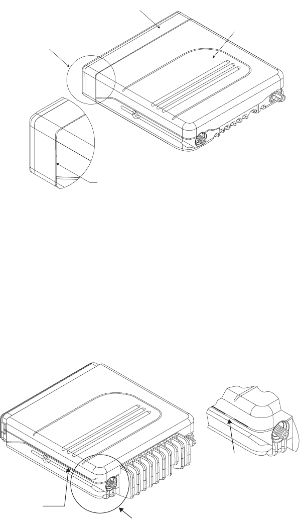
52
Remove the Top Cover 1. Insert a wide flat-blade screwdriver or like instrument in the
recess area on the side of the main chassis near the RF connector
end (see Figure 26).
2. Pry the cover off the chassis by pushing the handle of the
screwdriver in and toward the chassis. This will disengage the
snap between the cover and chassis.
3. Repeat Step 1 and Step 2 for the opposite side of the radio.
Remove the Interface
Board
1. Remove the antenna connector retaining clip by inserting a small
flat-blade screwdriver or like instrument between the clip and the
top of the cavity wall as shown in Figure 27. Gently pry upwards.
2. Remove the board screws with a T-10 Torx Driver.
3. Carefully remove the interface board by rotating it out of the
chassis. Slowly lift the board on the front edge while pushing up
on the board through the accessory connector opening. Pull the
board forward out of the chassis (see Figure 28).
Figure 25. Removing the Front Housing
Depress Snap Here
See Detail "A"
Front Housing
Main Chassis
Detail "A"
Figure 26. Removing the Top Cover
Disengage Snap
here and on
other side
See Detail A
Disengage
Snap here
Detail “A”
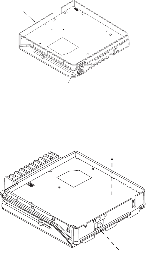
53
4. Retain the heat conductive insulator from under the regulator.
Transceiver Disassembly 1. Detach the RF cable assembly from the right-angle SMB connector
on the interface board.
2. Turn over the interface board. Remove the flex connector retainer,
4285168D01.
3. Gently lift the clasps of the 20-pin and 40-pin flex connectors.
Remove the 20-pin and 40-pin ends of the flex cable from the
transceiver leaving the 30-pin end attached to the interface board.
4. Loosen the screws for the two retainers holding the transceiver to
the interface board. Slide one of the retainers away from the edge
of the transceiver to free it.
5. Remove the transceiver from within the two retainers.
6. Detach the RF cable from the RF adapter plug. Unscrew the RF
adapter plug from the transceiver.
Figure 27. Removing the Antenna Connector Retaining Clip
Figure 28. Removing the Interface Board
Front
Pry Clip Off Here
2) Pull board
forward out
of chassis
1) Push up on board
through accessory
connector opening
54
VRS750 Reassembly NOTE: Replace all gaskets at each servicing to ensure proper
sealing of unit.
Transceiver Reassembly 1. Screw the RF adapter plug into the transceiver. Tighten until the
stop on the adapter is fully seated in the RF jack.
2. Connect the RF coax cable to the RF adapter.
3. Place the transceiver in between the two retainers, sliding one
sideways if needed.
4. Adjust the retainers so that they align with the groove between
the transceiver board and its chassis. Tighten the four screws of
the retainers. If needed, adjust the screws so that the transceiver
lays flat against the interface board.
5. Connect the 20-pin and 40-pin ends of the flex cable to the flex
connector. Gently close the clasps on the connectors.
6. Reattach the flex connector retainer, 4285168D01.
7. Turn over the board.
8. Connect the RF coax cable to the right-angle SMB connector on
the interface board.
Interface Board
Reassembly
1. Install a new gasket around the 25 pin connector and Antenna
connector located on the board.
2. Check that the foam seal is correctly positioned on the 25 pin
connector on the bottom side of the board.
3. Add the conductive insulator to the back of the regulator.
4. Insert the main board carefully at an appropriate angle
(approximately 30°) into the chassis. Start, but do not torque
down, screw number 6 per Figure 29 and Table 8.
5. Install the antenna retaining clip.
6. Attach the nylon washer to the regulator at screw hole number 4
as indicated in Figure 29.
7. Install the screws with 6-8 in-lbs of torque using a T-10 Torx driver
per sequence shown in Figure 29 and Table 8.
8. Place a new cover gasket around the chassis ensuring that it is
placed under the locking tabs and ledge at the front of the chassis
(see Figure 30). To ensure that the gasket remains seated along the
groove, twist the gasket between fingers down and toward the
chassis on both sides of the chassis.
9. If chassis is being replaced, add the plastic insert and seal into the
area at the back of the main chassis opposite the antenna
connector.
10. Install the top cover by engaging the hooks on front of the chassis
and rotating the cover back. Ensure that the side snaps on the
cover are engaged.
11. Install the front cover gasket over the front of the chassis
ensuring that the rectangular hole in the chassis aligns with the
rectangular hole in the gasket. Press the gasket flush against the
chassis to ensure proper sealing.
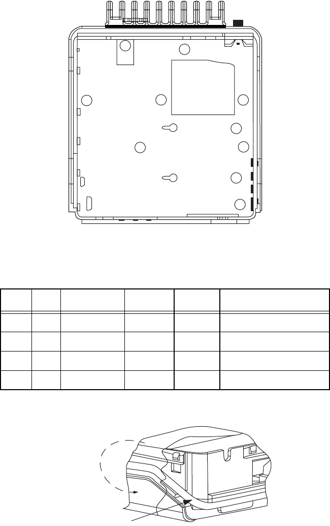
55
Assembly of Front Cover
to Main Chassis
Refer to exploded views on page 88 for parts referenced in this
procedure.
1. Install the 18 pin connector into the female connector (mounted
on the PC board) through the hole in the front of the chassis.
2. Place white remote retainer (4205395X01) over the 18 pin
connector.
Figure 29. VRS750 Torque Sequence
Table 8. VRS750 Torque Sequence
Step No. Screw P/N Bit Torque Notes
1 6 0310907A20 Torx T10 — Start Only
2 — — — Place Antenna Conn.
3 4-8 0310907A20 Torx T10 8 in-lb Number 6 Inclusive
4 1-3 0310907A20 Torx T10 8 in-lb
Figure 30. Cover Gasket Location
4
2
7
8
5
3
1
6
Cover gasket
Twist o-ring

56
3. Install the remote front housing over the 18 position connector
onto the front of the chassis ensuring that both snaps are
engaged.
4. Place the gasket within the recessed area for the 18-pin
programming connector.
5. Connect the Programming Connector Cover to the main chassis.
VRS Transceiver Field repair of the transceiver is not recommended. Contact your local
service representative for a replacement transceiver. If replacement of
the transceiver is necessary, refer to the Disassembly & Reassembly
section and the Tuning Procedure section.
VRS Tuning and
Alignment
The VRS is tuned at the factory and should not need to be realigned.
Refer to the proper manuals for programming and alignment for the
associated portable radio and mobile unit before attempting to
troubleshoot the VRS unit. If proper tuning of the associated radio fails
to correct a problem, the following procedure may be used to align the
VRS.
Setup
ASTRO Spectra Station
Cable Setup
Ensure that the ASTRO Spectra B+ cable is disconnected from the
power supply and the control head is off (WARNING: Never turn B+
power off with the control head still on.) Connect the VRS DB-25
cable (HKN6153A) into the accessory connector of the mobile.
Connect the other end of the VRS cable to the VRS. Set the test station
power supply to 13.8 Vdc and current limiter to 12 amps. Connect the
mobile’s B+ cable to the power supply (see Figure 31).
Tuning Procedure
Interface Board
Tuning Procedure
1. Place the VRS in the test mode:
a. Turn off the mobile radio control head.
b. Place the VRS into Test Mode by setting dipswitch S1 pins 1,
2, 3, and 4 to OFF.
c. Turn on the mobile control head and re-enable the VRS.
d. While in Test Mode, the VRS will not have portable priority
interrupt and will not transmit PL with VRS-to-portable
transmissions.
e. Figure 32 illustrates the relative placement of the tuning
potentiometers.
2. Adjust the VRS Deviation Level:
a. Set the Mobile Communications Analyzer RF output to
-50 dBm, with a standard test modulation (1 kHz tone, 3 kHz
deviation).
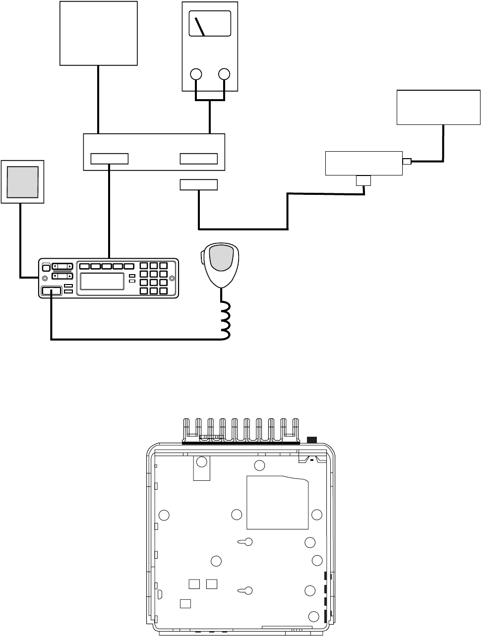
57
Figure 31. General Cabling Diagram
Figure 32. Tuning Potentiometers
Mobile
Communication
Analyzer DC Supply
+-
ASTRO Spectra Mobile
W7 Control Head
Speaker
Mobile
Microphone
HKN6153A
VRS750
VRS
Communication
Analyzer
4
2
7
8
5
3
1
6
R150
R148 R146
58
b. Set the Mobile Communications Analyzer frequency to the
current mobile mode.
c. Switch on the Mobile Communications Analyzer RF.
d. Adjust R150 on the VRS board until 3.0 kHz deviation is
obtained on the VRS Communications Analyzer.
e. Switch off the Mobile Communications Analyzer RF.
3. Adjust the Mobile Microphone Deviation Level:
a. Inject a 1 kHz tone at 80 mVrms into the mobile microphone.
b. Key the mobile microphone. (Refer to the ASTRO Spectra
Mobile service manual for specialized equipment.)
c. Adjust the signal level of the 1 kHz tone until 3.0 kHz
deviation is obtained on the Mobile Communications
Analyzer.
d. Adjust R148 on the VRS board until 3.0 kHz deviation is
obtained on the VRS Communications Analyzer.
e. Dekey the mobile microphone.
4. Adjust the Mobile Deviation Level:
NOTE: Set the VRS Communications Analyzer RF output to
-50 dBm with a standard test modulation (1 kHz tone,
3 kHz deviation) and any receive PL for which the VRS
is programmed (750 Hz deviation). If the receive PL for
“select mode” is not used, the Mobile
Communications Analyzer frequency may need to be
adjusted.
a. Set the Mobile Communications Analyzer frequency to the
current mobile mode.
b. Switch on the VRS Communications Analyzer RF.
c. Adjust R146 on the VRS board until 3.00 kHz deviation is
obtained on the Mobile Communications Analyzer.
d. Switch off the VRS Communications Analyzer RF.
5. Check the VRS RF Sensitivity:
a. Set the VRS Communications Analyzer RF output to -115 dBm
with a standard test modulation (1 kHz tone, 3 kHz deviation)
and any receive PL for which the VRS is programmed (750 Hz
deviation).
NOTE: If the receive PL for “select mode” is not used, the
Mobile Communications Analyzer frequency may
need to be adjusted.
b. Switch on the VRS Communications Analyzer RF. The unit
should not retransmit this signal to the Mobile
Communications Analyzer.
c. Slowly increase the input signal. The unit should begin
repeating to the Mobile Communications Analyzer at no
more than -104 dBm.
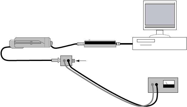
59
d. Switch off the VRS Communications Analyzer RF.
6. Take the VRS out of test mode:
a. Turn off mobile control head and set the dipswitch S1 pins 1,
2, 3, and 4 to ON.
b. Turn on the mobile control head and re-enable the VRS.
7. Tuning is complete.
Transceiver Board Tuning
Procedure
The transceiver board can be tuned using the Global Tuner when the
VRS750 is in ATE Test Mode. Connect the VRS750 to the test box
(RLN6394A) instead of the ASTRO Spectra mobile using the VRS750
ATE Cable (3080384N02) as shown in Figure 33. Before applying
power, set dipswitch S1 pin 1 to ON and pins 2, 3, and 4 to OFF. This
configures the VRS750 for ATE Test Mode. Make the appropriate
connections to the VRS750 test box for power and audio. Once this is
complete the VRS750 can be tested and tuned using the Global Tuner.
Front End Filter Tuning NOTE: Tuning is normally not required for VHF radios. It
should only be performed if a radio has poor
sensitivity. VHF radios are only tuned at one softpot
frequency (F3: The values for the untuned frequencies
are determined by adding the offset, calculated by
subtracting the default softpot value for frequency F3
from the tuned softpot value for frequency F3. The
default softpot values are listed in Table 9.)
Figure 33. ATE Test Mode Configuration
VRS750
VRS750
TEST BOX
(RLN5394A)
VRS750
PROG. CABLE
RX AUDIO
AND EXT MIC
CONNECTORS
SRIB
DC SUPPLY
VRS750 ATE CABLE
(3080384N02)
CONNECT TO THE PCs
COM PORT

60
Under Rx Align, select the Front End Filter option.
1. Inject a -70 dBm RF Signal with Frequency F1 (for UHF)/F3 (for
VHF) modulated with 1 kHz tone at 60% rated deviation (see
Table 10) into the VRS750. A 1 kHz tone must be detected at the
RX Audio connector on the test box to verify that the radio is
receiving.
2. Measure the RSSI voltage with a DC voltmeter capable of 1 mV
resolution at test point 111 on the VRS750. It is recommended
that an RCA filter (1.5 K-47 uF) be added at the input of the
voltmeter to reduce RSSI noise.
3. Increment the softpot value by adjusting the slider, keying in the
softpot values in the edit box (press ENTER to confirm selection)
or using the spin control until the maximum RSSI voltage has
been achieved.
4. For UHF and VHF radios:
a. UHF radios: Choose the next frequency and repeat steps 1 to
3 until all seven tuning points are done.
b. VHF radios: Calculate the softpot offset by subtracting the
default softpot value for F3 from the tuned softpot value for
F3. Add the calculated offset to all default values and enter the
results in the edit boxes for the appropriate softpot
frequencies.
5. Press Program to commit the softpot values into the codeplug.
Table 9. Default Softpot Values for VHF and UHF
Frequency Point
Softpot Value (Decimal)
VHF UHF
F1 36 38
F2 57 48
F3 84 79
F4 124 110
F5 166 135
F6 195 161
F7 225 186

61
Rated Volume Tuning Under Rx Align, select Rated Volume.
NOTE: The received audio output is taken from the positive
terminal of C189.
1. Inject a -47 dBm RF Signal modulated with 1 kHz tone at the 60%
rated deviation (see Table 10) into the VRS750.
2. Adjust the softpot value by using the slider, keying in the edit box
(press ENTER to confirm selection/send a softpot value), or via
the spin controls. Repeat this until a 1.58 Vrms ±200 mVrms
signal can be obtained at the positive terminal of C189.
3. Press Program to commit the softpot value into the codeplug.
Reference Oscillator
Warp
NOTE: Perform this operation prior to all other transmit
tuning operations in order to minimize heating and
because of the impact of warp on signaling operations.
1. Under Tx Align menu, select Reference Oscillator Warp.
2. There is only 1 frequency point shown which is always the last
non 0 transmit frequency point, which will normally be F7.
3. Click on the slider thumb. Press PTT Toggle to key up the radio at
the corresponding frequency point.
4. Monitor the transmit frequency.
5. Adjust the slider, spin or edit control (press ENTER to confirm
selection/send a softpot value) until the frequency is as close as
possible to the indicated transmit frequency (refer to Table 11).
6. Dekey the radio by pressing PTT Toggle.
Table 10. VRS750 Deviation Levels
Channel Spacing
(kHz)
Rated System
Deviation (kHz)
Signal Generator
Deviation (kHz)
12.5 2.5 1.5
20 4.0 2.4
20 5.0 3.0
25 5.0 3.0
30 5.0 3.0
Table 11. Frequency Error Specifications
RF Band Target (Hz)
VHF (136-174) ±200
UHF Band 1 (403-470) ±200
UHF Band 2 (450-527) ±200
62
7. Program the warp value into the radio by pressing the Program
button.
8. Exit the Reference Oscillator Warp function.
VCO Attenuation NOTE: The Transmit Deviation Limit softpot sets the
maximum deviation of the carrier. Tuning is
performed for 12.5 kHz, 20 kHz, and 25 kHz channel
spacing. Tuning for 25 kHz channel must be done first
for all frequency points. Tuning for 12.5 kHz and 20
kHz channel spacing determines only the offset to the
previously tuned deviation for 25 kHz tuning channel
spacing. For (12.5, 20 kHz) channel spacing, only the
last non 0 transmit frequency point (normally F7) will
be used for tuning.
VCO Attn. 25 kHz 1. Under the Tx Align menu, select VCO Attn. 25 kHz.
2. Begin with the lowest frequency. Select the thumb of the slider at
the lowest frequency point and then press the PTT Toggle button
to key up the radio at the corresponding frequency point. The
spin control can also be toggled via its up/down arrow buttons.
The softpot value can also be typed into the edit control (press
ENTER to confirm selection/send a softpot value).
3. Inject a 1 kHz at 80 mVrms signal into the external mic connector
on the test box (VRS750 input).
4. Note down the deviation obtained.
5. Adjust the slider, adjust the spin control or key in softpot values
(press ENTER to confirm) for the frequency point until the
deviation is within range as defined in Table 12.
6. Dekey radio (press the PTT Toggle button). Choose the next
frequency, key up and repeat steps 3 to 6 until all seven tuning
points are done.
7. Program the softpot value by pressing the Program button.
8. Exit the VCO Attn. 25 kHz function.
VCO Attn. 20 kHz NOTE: Tuning of Modulation Balance Attn. and VCO Attn. for
25 kHz channel spacing must be done first.
1. Under the Tx Align menu, select VCO Attn. 20 kHz.
2. Press PTT Toggle to key up the radio at the last non 0 transmit
frequency point (normally F7).
3. Inject a 1 kHz at 80 mVrms signal into the external mic connector
on the test box (VRS750 input).
4. Note down the deviation obtained.
5. Adjust the slider, adjust the spin control or key in softpot values
(press ENTER to confirm) for the frequency point until the
deviation is within range as defined in Table 12.
6. Press PTT Toggle to dekey the radio.
7. Program the softpot value by pressing the Program button.

63
8. Exit the VCO Attn. 20 kHz function.
VCO Attn. 12.5 kHz NOTE: Tuning of VCO Attn. for 25 kHz channel spacing must
be done first.
1. Under the Tx Align menu, select VCO Attn. 12.5 kHz.
2. Press PTT Toggle to key up the radio at the last non 0 transmit
frequency point (normally F7).
3. Inject a 1 kHz at 80 mVrms signal into the external mic connector
on the test box (VRS750 input).
4. Note down the deviation obtained.
5. Adjust the slider, adjust the spin control or key in softpot values
(press ENTER to confirm) for the frequency point until the
deviation is within range as defined in Table 12.
6. Press PTT Toggle to dekey the radio.
7. Program the softpot value by pressing the Program button.
8. Exit the VCO Attn. 12.5 kHz function.
PA Bias Tuning UHF/VHF
VRS750s (Procedure 1)
IMPORTANT NOTE: Tuning must be performed for both High
and Low power for UHF and VHF radios.
Take note that Procedure 1 IS NOT TO BE
PERFORMED for UHF low power level
tuning. Please refer to Procedure 2.
1. Ensure that the radio’s antenna output is terminated to a 50 Ohm
load. This is to prevent self destruction of the PA.
2. Under Tx Align, select PA Bias, select High Power.
3. Measure/read the dc current drawn from radio (specifications will
vary from radio to radio). Call this X. This value should typically
range from 70-100 mA or 0.07-0.1 A.
4. Press Toggle Voltage to enable the PA control voltage edit box/
spin control.
5. Increase the Voltage softpot value and measure/read from current
meter. Call the new value Y.
6. Increase Y until Y-X is within the range given for PA current in
Table 13.
7. Press Toggle Voltage again to disable the PA control voltage edit
box/spin control.
Table 12. Deviation Specifications for VRS750 UHF/VHF Radios
Band Channel Spacing (kHz) Deviation (kHz)
UHF/VHF 12.5 2.20-2.30
UHF/VHF 20 3.40-3.60
UHF/VHF 25 4.40-4.60

64
8. Press Toggle Bias 1 in order to enable the PA Bias softpot.
9. Increase the softpot value to obtain Z until Z-Y is within the
range for Bias Current as indicated in Table 13.
10. Press Toggle Bias 1 again to disable the PA Bias softpot.
11. Program the Bias softpot into the radio’s codeplug via pressing
Program.
12. Exit the PA Bias High Power function.
13. Under Tx Align, select PA Bias, Low Power. (If UHF, skip to step
15 and continue to Procedure 2.)
14. Repeat steps 3-11.
15. Exit the PA Bias Low Power function.
PA Bias Tuning for UHF
Low Power VRS750s
(Procedure 2)
NOTE: Failure in the instructions below means that you
cannot get a reading which is within the range of the
current window as specified in Table 14 for each
individual step.
Ensure that the radio’s antenna output is terminated to a 50 Ohm
load. This is to prevent self destruction of the PA.
STEP 1 1. Under Tx Align, select PA Bias, select Low Power.
2. Measure/read the dc current drawn from radio (specifications will
vary from radio to radio). Call this X. This value should typically
range from 70-100 mA or 0.07-0.1 A.
3. Press Toggle Voltage to enable the PA control voltage edit box/
spin control.
4. Increase the Voltage softpot value and measure/read from current
meter. Call the new value Y.
5. Increase Y until Y-X is within the range given for PA current in
Table 14 (STEP 1) below.
****** If a failure occurs, go to STEP 2 otherwise proceed
6. Press Toggle Voltage again to disable the PA control voltage edit
box/spin control.
7. Press Toggle Bias in order to enable the PA Bias softpot.
8. Increase the softpot value to obtain Z until Z-Y is within the
range for Bias Current as indicated in Table 14 (STEP 1).
Table 13. PA Bias High Power Specifications UHF/VHF VRS750s
RF Band PA Current (mA) Bias Current (mA)
VHF 90-110 90-110
UHF Band 1 30-45 600-700
UHF Band 2 30-55 400-480

65
****** If a failure occurs, go to STEP 3 otherwise proceed
9. Press Toggle Bias again to disable the PA Bias softpot.
10. Program the Bias softpot into the radio’s codeplug via pressing
Program.
11. Exit the PA Bias Low Power function.
STEP 2 1. Increase Y until Y-X is within the range given for PA current in
Table 14 (STEP 2).
2. Press Toggle Voltage again to disable the PA control voltage edit
box/spin control.
3. Press Toggle Bias in order to enable the PA Bias softpot.
4. Increase the softpot value to obtain Z until Z-Y is within the
range for Bias Current as indicated in Table 14 (STEP 2).
****** If a failure occurs, go to STEP 3 otherwise proceed
5. Press Toggle Bias again to disable the PA Bias softpot.
6. Program the Bias softpot into the radio’s codeplug via pressing
Program.
7. Exit the PA Bias Low Power function.
STEP 3 1. Press Toggle Bias twice to reset the softpot value.
2. Press Toggle Bias again to disable the PA Bias softpot.
3. Measure/read the dc current drawn from radio (specifications will
vary from radio to radio). Call this X. This value should typically
range from 70-100 mA or 0.07-0.1 A.
4. Press Toggle Voltage to enable the PA control voltage edit box/
spin control.
5. Increase the Voltage softpot value and measure/read from current
meter. Call the new value Y.
6. Increase Y until Y-X is within the range given for PA current in
Table 14 (STEP 3).
7. Press Toggle Voltage again to disable the PA control voltage edit
box/spin control.
8. Press Toggle Bias in order to enable the PA Bias softpot.
9. Increase the softpot value to obtain Z until Z-Y is within the
range for Bias Current as indicated in Table 14 (STEP 3).
Table 14. PA Bias Low Power Specification for VRS750s (UHF Only)
Step PA Current (mA) Bias Current (mA)
STEP 1 20-30 630-750
STEP 2 30-45 750-900
STEP 3 40-55 600-750
66
10. Press Toggle Bias again to disable the PA Bias softpot.
11. Program the Bias softpot into the radio’s codeplug via pressing
Program.
12. Exit the PA Bias Low Power function.
NOTE: After tuning a transceiver, go back and tune the
interface board (details in this chapter) and then adjust
the output power and squelch settings (see Chapter 2).

67
Troubleshooting Charts 8
Introduction to this
Section
This section contains detailed troubleshooting flowcharts. These
charts should be used as a guide in determining problem areas. They
are not a substitute for knowledge of circuit operation and astute
troubleshooting techniques. It is advisable to refer to the related circuit
descriptions in the “Hardware Detailed Theory of Operation,”
Chapter 6.
List of
Troubleshooting
Charts
Chart
Number Description
Page
Number
1 VRS Enable Failure 68
2 Error 12/10 69
3 Error 12/81 69
4 Error 12/82, Codeplug Checksum Error* 69
5 Error 12/84, Configuration Register Corruption* 69
6 Error 12/88, HC11 RAM Failure 69
7 VRS 001, VRS Synthesizer Lock Failure 70
8 Single Tone Encode Failure 71
9 Single Tone Failure 72
10 Base-to-Portable Repeat Failure 73
11 Portable-to-Base Repeat Failure 74
12 VRS ICM Audio Failure 75
13 Serial Bus Failure 76
14 Portable Audio at Local Speaker Issue 77
15 Programming/Tuning Failure 78
*Older VRS-EP versions may show a 12/82 Error flashing every 5 seconds for
Codeplug Checksum Error, and a 12/82 Error at power-up only for
Configuration Register Corruption.
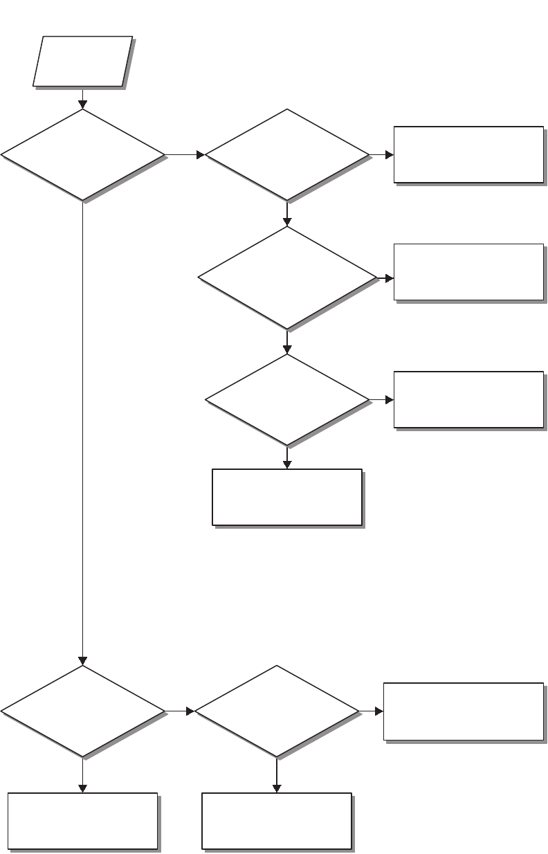
68
Chart 1—VRS Enable Feature
VRS ENABLE FAILURE
Ye s
No
Ye s
No
Ye s
Ye s
No
Ye s
No
Ye s
No
No
START
Is VRS
button enabled in
the mobile
codeplug?
Is mobile
codeplug programmed
for VRS VIP?
Is the mobile
codeplug programmed
for VRS VIP?
Program mobile codeplug for
VRS button operation.
Is
"VRS BOTH"
message displayed on
button press?
VRS is now enabled.
Reset system and start over.
If CSQ is being detected the
VRS will not enable.
Is
the mobile
codeplug programmed for
VRS VIP active
state?
Program mobile codeplug for
VRS VIP.
Is switch in
correct VIP?
Program mobile codeplug for
proper VRS VIP active state.
Check VRS VIP switch
input.
Move switch or reprogram
mobile codeplug.

69
Chart 2—Error 12/10
Ye s
No
Ye s
No
Ye s
No
START
Is the VRS
mobile interface cable
connected?
Are the
regulated voltages
present?
Reconnect the
cable.
Is the
VRS750 firmware
correct?
Troubleshoot the
regulator circuit.
Check the
transceiver board.
Flash the VRS750
with the correct
firmware.
ERROR 12/10
Chart 3—Error
12/81
START
Reprogram the
Flash Memory.
ERROR 12/81
Chart4—Error
12/82, Codeplug
Checksum Error
START
Reprogram the
VRS750 Codeplug.
ERROR 12/82
Chart 5—Error 12/84, Configuration
Register Corruption
Ye s
No
START
Reflash the VRS750
with the correct
version firmware.
Reset the system.
Is the
12/84 error still
displayed?
Replace the
transceiver board.
Problem is
corrected.
ERROR 12/84
Chart 6—Error 12/88, HC11
RAM Failure
Replace
the transceiver.
Error
12/88
ERROR 12/88
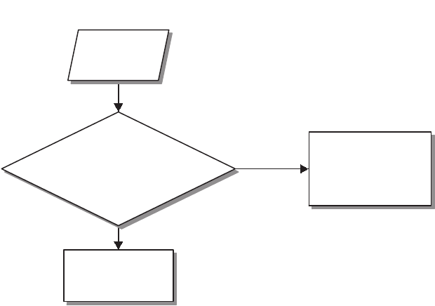
70
Chart 7—VRS 001, VRS Synthesizer Lock Failure
VRS 001 FAILURE
Ye s
No
Does the
Freq. Band field in
ASTRO CPS match the freq. Band
of the VRS750 attached to
the mobile?
Replace the
transceiver board.
Correct the freq. band
field for the VRS750 in
the ASTRO mobile
codeplug.
START

71
Chart 8—Single Tone Encode Failure
No
No
No
Ye s
No
Ye s
No
Ye s
No
Is there
continuity between
J30-19 and J20-7 on the
flex cable?
Check and/or
replace C104.
Replace the
transceiver.
Replace the flex
cable.
Replace the
transceiver.
Replace the flex
cable.
START
SINGLE TONE ENCODE FAILURE
Ye s
Ye s
Ye s
Is
3.3VDC square wave
at R114 during Single
Tone burst?
Is
80mVpp sinewave
at TP104?
Is
there continuity
between J30-6 and
J40-21 on the flex
cable?
Is the
sinewave present at
TP101?
Check and/or
replace U100,
U124.
Is
the sinewave
present at the negative
terminal of C104?
Verify that pin 10 of U101 is
0VDC during the Single
Toneburst. Check U101 and
Q106.
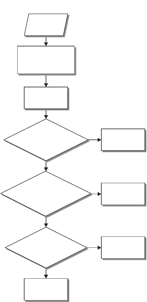
72
Chart 9—Single Tone Failure
Ye s
No
Ye s
No
Ye s
No
START
Verify that the VRS750
dip switches are set to
normal operation.
Does
TP105 pulse ~5VDC
when the volume button
is pressed?
Does J30-21
pulse to ~0VDC when
the volume button is
pressed?
Check the mobile
to VRS cable.
Is there
continuity between
J30-21 and J20-9 on the
flex cable?
Check and/or
replace U103 and
Q103.
Check and/or
replace the
transceiver.
Replace the flex
cable.
Verify that J30-20
(boot control) is
~3.3VDC.
SINGLE TONE FAILURE

73
Chart 10—Base-to-Portable Repeat Failure
Ye s No
Ye s
No
Ye s No
Ye s
No
Ye s
No
Ye s
No
Ye s
No
Ye s
No
Ye s
No
Ye s
No
Ye s
No
START
Verify that the VRS750
dip switches are set to
normal operation.
Activate the
VRS750.
Is "VRS
BOTH" displayed
briefly?
Provide an
on-channel RF
signal to the mobile.
The VRS750 is not
enabled and audio
will not be heard.
Is
audio present at
C135?
Is audio
present @ U101 pin
5?
Chekc mobile and
its connection to
the VRS.
Is audio
present @ U101 pin
4?
Check U104.
Adjust R150 if
necessary.
Is
audio present @
TP101?
Verify that the
local mic is not
pressed.
Is
audio present
@ J30-19?
Is pin 10
of U101 HIGH
-9.6VDC?
Is
there continuity
between J30-19 and
J20-7 of the flex
cable?
Replace the
transceiver. Replace U101.
Is
there continuity
between J30-8 and
J40-23 on the flex
cable?
Is pin
9 of U101 low
(0VDC)?
Repair/replace
U101.
Is
there continuity
between J30-15 and
J40-23 on the flex
cable?
Replace the
transceiver.
Replace the flex
cable.
Check and/or
replace Q106.
Replace the flex
cable.
Repair/replace
Q114.
Replace the flex
cable.
BASE TO PORT. AUDIO ISSUES

74
Chart 11—Portable-to-Base Repeat Failure
PORTABLE-TO-BASE AUDIO ISSUE
Ye s
Ye s
Ye s
No
Ye s
Ye s
Ye s
No
No
No
No
Ye s
NoNo
Verify dip switches
are set to normal
operation.
Is the
1kHz tone present @
J30-11?
Is the
1kHz tone present at
TP102?
Replace
transceiver.
Is
audio present @
TP125?
Check U104 and
replace if
necessary.
Is mobile
transmit deviation
3kHz?
Check solder connextions
for C132, C133, and T2.
Replace if necessary.
Complete.
Adjust R146 to obtain
3kHz deviation from
mobile.
Activate the
VRS750.
Is "VRS
BOTH" displayed
briefly?
Provide an on channel RF
signal with an Access or
Mode Steering PL to the
VRS750.
The VRS750 is not
enabled and will
not repeat.
Is
audio present @
TP128?
Is
there continuity
between J30-11 and
J40-28 on the flex
cable?
Replace the
transceiver.
Replace the flex
cable.

75
Chart 12—VRS ICM Audio Failure
IN-CAR-MONITOR AUDIO ISSUES
Ye s
Ye s
Ye s
Ye s
Ye s
Ye s
No
Ye s
No
Ye s
Ye s
No
No
No
No
No
No
Ye s No
Verify that the VRS750
dip switches are set
for normal operation.
PTT the mobile's local
mic and talk into it.
Is
audio present at
C134?
Refer to the
Base-to-Portable
troubleshooting chart.
Is audio
present @ pin 3 of
U101.?
Check the mobile
and its mic
connections.
Check U104 and
adjust R148 if
necessary.
Check and/or
replace U101.
Check and/or
replace Q114.
Activate the
VRS750.
Is "VRS
BOTH" displayed
briefly?
During
Base-to-Portable
communications, is audio heard
@ the portable?
Check C185 and C166 to
make sure they have not
been shorted to ground.
Verify that the
MOBILE_MIC_HI line in
the mobile to VRS is ok.
Is audio
present @ pin 1 of
U101?
Is audio
present @ pin 15 or
U101?
Is pin 9 of
U101 a logic HIGH -
9.6VDC.?
Is pin 10
of U101 a logic HIGH -
9.6VDC.?
Check and/or
replace U101.
Check and/or
replace Q106.
Is
audio present @
J30-19?
Is
there continuity
between J30-19 and
J20-7 of the flex
cable?
Check and/or
replace C104.
Replace the
transceiver.
Replace the flex
cable.
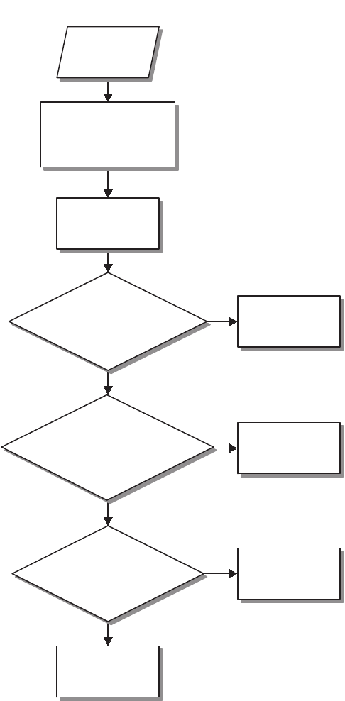
76
Chart 13—Serial Bus Failure
Ye s
No
Ye s
No
Ye s
No
START
Verify that the VRS750
dip switches are set to
normal operation.
Does
TP105 pulse ~5VDC
when the volume button
is pressed?
Does J30-21
pulse to ~0VDC when
the volume button is
pressed?
Check the mobile
to VRS cable.
Is there
continuity between
J30-21 and J20-9 on the
flex cable?
Check and/or
replace U103 and
Q103.
Check and/or
replace the
transceiver.
Replace the flex
cable.
Verify that J30-20
(boot control) is
~3.3VDC.
SERIAL BUS FAILURE
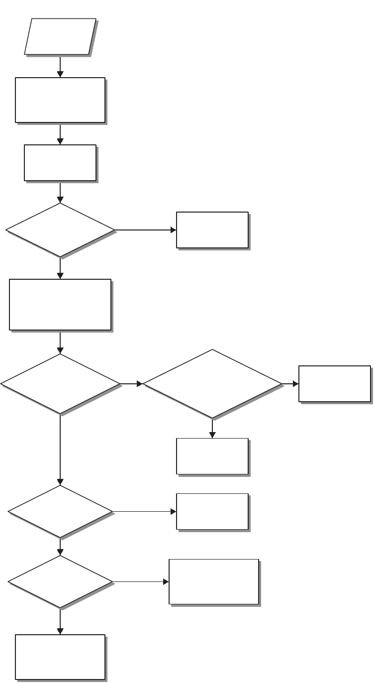
77
PORTABLE AUDIO AT LOCAL SPEAKER ISSUE
Ye s
Ye s
Ye s
Ye s
No
No
No
No
Ye s
No
Is
audio present @
EXT_SPKR+ J30-17?
Is
audio present at
C183?
Is
there continuity
between J30-17 and
J20-4 on the flex
cable?
Verify that the VRS750
dip switch settings are
set to normal operation.
Is
audio present at
TP108?
Repair and/or
replace U107.
Adjust mobile volume
on controlhead to level
7.
Check solder
connections for C183,
C103, and T1.
Activate the
VRS750.
Is "VRS
BOTH" displayed
briefly?
Provide an on-channel RF
signal with the proper
Access or Mode Steering
PL to the VRS750.
The VRS750 is not
enabled and audio
will not be heard.
START
Replace the
transceiver.
Replace the flex
cable.
Chart 14—Portable Audio at Local Speaker Issue

78
Chart 15—Programming/Tuning Failure
ATE Test Normal
Ye s
Ye s
Ye s
No
No
No
No
Ye s
Ye s
Ye s
Ye s
No
Ye s No
No
No
No
Ye s
No
Ye s
Start
Is
the VRS750 in ATE
Test or Normal Mode?
Is 13.8V
supplied to the test
box?
Is the mobile radio
powered on?
Is the SRIB
connected to the computer
and powered on?
Plug the 25 pin connector
into the SRIB and the 18
pin connector into the
VRS750.
Is the
Flashing Adapter being
used?
Connect the SRIB to the
serial port of the
computer using a null
modem cable and make
sure it is turned on.
Verify that P101-7 is
connected to J30-24.
Is the SRIB
connected to the computer
and powered on?
Disconnect the
programming cable from
the VRS750.
Did
the mobile radio
reset?
Plug the
programming cable
back in to the
VRS750 and try
again.
Reset the mobile
radio.
Plug the programming
cable back in to the
VRS750.
Is "PROG
VRS" displayed on the mobile
control head?
Tr y
programming
again.
A.
Connect the SRIB to the
serial port of the
computer using a null
modem cable and make
sure it is turned on.
Verify that the
mobile is
powered on. If
not, power the
mobile on and
start over.
A.
Is
the VRS750
programming cable
securely plugged into the
VRS750 and an
SRIB?
Supply 13.8V to the
VRS750 test box.
Is
"PROG VRS"
displayed on the mobile
control head?
Power on the
mobile radio.
Is the
switch in the B
position?
Remove the flashing
adapter and cycle
power to the VRS750.
Place the switch in the B
position and cycle power to
the VRS750. The A position
is for flashing only.
Cycle power to the VRS750
and try again. If the problem
persists, try a different
programming cable.
PROGRAMMING AND
TUNING ISSUES
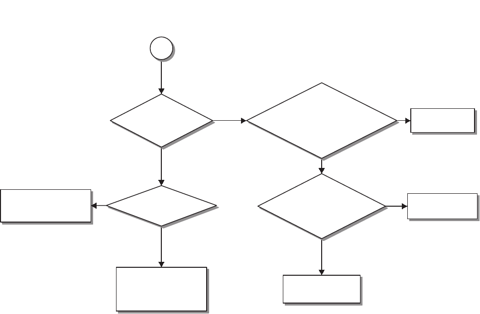
79
Chart 15—Programming/Tuning Failure (Cont.)
Ye s
No
Ye s
No
Ye s
No
Ye s
No
Is
the switch in the B
position?
Is there a 18 pin
extension in the connector,
2805347X01, on the front of the
VRS750?
Remove the Flashing
Adapter and reset the
mobile. The Flashing
adapter could be bad.
Place the switch in the B
position and reset the
mobile.
Is the
cathode of
VR121 grounded when
plugged into the
SRIB?
Replace the
header block.
Verify that P101-7 is
connected to J30-24.
Replace the
programming cable.
Is the
Flashing Adapter
being used?
A.
PROGRAMMING AND
TUNING ISSUES (CONT.)

80
Notes

81
Diagrams and Parts Lists 9
Introduction to this
Section
This section contains schematics, a component layout diagram, an
exploded view, and electrical and exploded view parts lists.
List of Diagrams
and Parts Lists Description
Page
Number
Printed Circuit Board Electrical Parts List 83
Printed Circuit Board Component Location Diagram 84-85
Printed Circuit Board Schematic Diagram 86-87
Exploded View and Exploded View Parts List 88
VRS-to-Mobile Cable 89
VRS-to-Siren Cable 89
VRS750 Programming Cable 90
VRS750 Programming Cable Schematic Diagram 90
VRS750 Flashing Adapter Schematic Diagram 90

82
Notes

83
VRS750
V
e
hi
cu
l
ar
R
epeater
S
ystem
Printed Circuit Board Electrical Parts List
(PLN7780A)
Notes:
1. For optimum performance, order replacement diodes, transistors,
and circuit modules by Motorola part number only.
2. When ordering crystals, specify carrier frequency, crystal frequency,
crystal type number, and Motorola part number.
3. Part value notations:
p=10
-12
µ=10
-6
k=10
3
n=10
-9
m=10
-3
M=10
6
ITEM MOTOROLA
PART NUMBER DESCRIPTION
CAPACITOR, Fixed; pF:
unless
otherwise stated
C100 2113740F59 220
C101 2113740F39 33
C102 2113740F59 220
C103, 104 2311049A08 Polar, 1 µF
C105 2113741B69 0.1 µF
C107 2113740F59 220
C108 2113741B69 0.1 µF
C109 2113740F59 220
C111, 112 2113740F59 220
C113 2113741F33 2200
C114 thru 116 2113741A45 .01 µF
C117 2113741A49 .015 µF
C118 2113740A79 1000
C119 2113743B21 0.22 µF
C120 2113741B69 0.1 µF
C121 2113740B49 100
C122 thru 131 2113740F59 220
C132, 133 2311049A08 Polar, 1 µF
C134, 135 2113743E20 0.1 µF
C136 2113740F59 220
C137 2380090M40 Polar, 2200 µF
C138, 139 2113740F59 220
C140 2113743E20 0.1 µF
C141 2113741A45 .01 µF
C142 2113740F59 220
C143 2113741B69 0.1 µF
C145 2113740A79 1000
C146, 147 2113740F59 220
C148 2311049A08 Polar, 1 µF
C149 2311049A19 Polar, 10 µF
C150 2113740F59 220
C151 2311049A19 Polar, 10 µF
C152 2113740F59 220
C153 2311049A19 Polar, 10 µF
C154 2113740F59 220
C155 2311049A19 Polar, 10 µF
C156 2380090M25 Polar, 100 µF
C157 thru 161 2113740F59 220
C162 2380090M25 Polar, 100 µF
C164 thru 167 2113740F59 220
C168 2113743E20 0.1 µF
C170 2113740F59 220
C171 2113743E20 0.1 µF
C172, 173 2113740F59 220
C175 2113740F59 220
C179 2113740F59 220
C180 2113740A79 1000
C182 2311049A19 Polar, 10 µF
C183 2311049A08 Polar, 1 µF
C184 2113740F59 220
C185 2113743A13 0.047 µF
C188 2113740F59 220
C189 2311049A08 Polar, 1 µF
C190 2113741F21 680
C191 2113740F59 220
C194 2113740A79 1000
C195 2113740F59 220
C196 2113743E20 0.1 µF
C197 2113740F59 220
C198 2113743E20 0.1 µF
C199 2113740F59 220
C200 2113743E20 0.1 µF
C201 thru 208 2113740F59 220
DIODE:
See Note 1
D100, 101 4813825A08 MBD701
D102 4813832C77 Transient supressor, 24 V
FUSE:
F100 6580542Z01 3 A
JACK:
J30 0985173D01 Connector, 30 pin flex
COIL, RF:
L101 2505462S03 Inductor, 1000 µH
PLUG:
P101 0905904V02 Connector, J
P102 2805429W03 Connector, P
TRANSISTOR:
See Note 1
Q100, 101 4880141L02 NPN
Q102 4813824A17 PNP
Q103 4880141L02 NPN
Q104 4813824A17 PNP
Q106 4880141L02 NPN
Q109 thru 112 4880141L02 NPN
Q113 4813821A21 nchan_tmosfet_gsd
Q114, 115 4880141L02 NPN
RESISTOR: Ohms ±5%; 1/8 W
unless otherwise stated
R101 0662057A93 68 k
R102 0662057A73 10 k
R104, 105 0662057A25 100
R106 0662057A65 4.7 k
R107 0662057A69 6.8 k
R108 0662057A93 68 k
R109 0662057A97 100 k
R110 0662057A77 15 k
R111 0662057A83 27 k
R112, 113 0662057A97 100 k
R114 0662057B10 330 k
R115 0662057A94 75 k
R116 0662057A84 30 k
R117, 118 0662057A65 4.7 k
R119 0662057A69 6.8 k
R120, 121 0662057A73 10 k
R122, 123 0662057A83 27 k
R124 0662057A73 10 k
R125 0662057A91 56 k
R126 0662057A77 15 k
R127 0662057A73 10 k
R128 0662057P95 100 k, 1%
R129 0662057P27 27.4 k, 1%
R130 0662057P22 22.1 k, 1%
R131 0662057P95 100 k, 1%
R132, 133 0662057A65 4.7 k
R136, 137 0662057A73 10 k
R138 0662057A65 4.7 k
R139 0662057A49 1 k
R140, 141 0662057A65 4.7 k
R142 0662057A49 1 k
R143 0662057A65 4.7 k
R145 0662057A89 47 k
R146 1813905A11 Pot, 20 k
R147 0662057A65 4.7 k
R148 1813905A11 Pot, 20 k
R149 0662057A91 56 k
R150 1813905A11 Pot, 20 k
R151 0662057A97 100 k
R155 0662057A73 10 k
R156 0662057A49 1 k
R157 0662057A77 15 k
R158 0662057A38 360
R159 0662057A55 1.8 k
R160 0662057A77 15 k
R161 0662057A47 820
R162 thru 164 0662057A73 10 k
ITEM MOTOROLA
PART NUMBER DESCRIPTION
R165 0662057A56 2 k
R166 0662057A65 4.7 k
R171 0662057T64 47.5 k 1%
R172, 173 0662057A73 10 k
R174 0662057P27 27.4 k, 1%
R175 0662057A73 10 k
R180, 181 0662057A65 4.7 k
R182 0662057A49 1 k
R183 0662057A73 10 k
R184 0662057A65 4.7 k
R200 0662057A65 4.7 k
R210 0662057A49 1 k
R211, 212 0662057A73 10 k
R213' 0662057A65 4.7 k
R215 0662057A83 27 k
R216 0662057B26 1.5 M
R217 0662057A49 1 k
R220 0662057B47 0
R221 0662057A81 22 k
R224 0662057A97 100 k
R225 0662057A73 10 k
R226, 227 0662057A65 4.7 k
R228, 229 0662057A73 10 k
SWITCH:
S1 4080564C02 Dip
TRANSFORMER:
T1, T2 2584422T02 6-pin
INTEGRATED CIRCUIT MODULE:
See Note 1
U100 5113818A03 MC33072-1
U101, 102 5184704M60 MC14053B
U103 5113806A37 MC14106
U104 5113819A04 MC3303
U105 5184704M60 MC14053B
U107 5113818A03 MC33072-1
U111 5113816A03 MC78L05A
U118 5105109Z13 LT1129
U124 5113819A04 MC3303
U129 5105469E18 LM317T
DIODE:
See Note 1
VR102 thru 109 4805129M35 Zener, 13, 5.6 V
VR110 4813830A28 Zener, 13, 15 V
VR112, 113 4805129M35 Zener, 13, 5.6 V
VR115 4813830A28 Zener, 13, 15 V
VR118 4805129M35 Zener, 13, 5.6 V
VR121 4805129M35 Zener, 13, 5.6 V
VR123 4805129M35 Zener, 13, 5.6 V
CONNECTOR:
W101 0984345R02 SMB Jack Rt. Ang PCB
W102 0905901V10 J, Antenna Connector
MISCELLANEOUS:
8485176D01 Board, PC
0200835638 Nut
0300114832 Screw
ITEM MOTOROLA
PART NUMBER DESCRIPTION
VRS750 Vehicular Repeater System
Printed Circuit Board Electrical Parts List (PLN7780A)
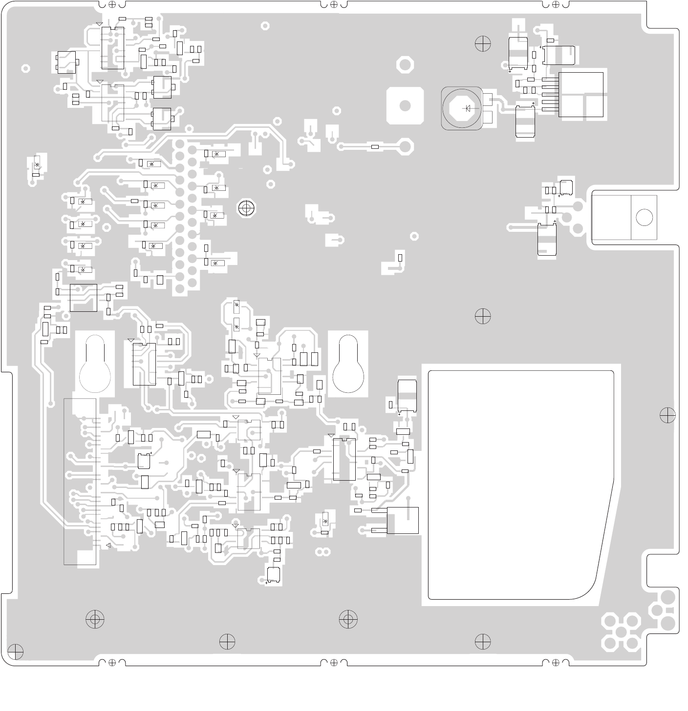
84
C100
C101
C102
C104
C105
C107
C108
C109
C111
C112
C113
C114
C115
C116
C117
C118
C119
C120
C121
C122
C123
C124
C125
C126
C127
C128
C129 C130
C131
C134
C135
C136
C138
C139
C140
C141
C142
C143
C145
C146
C147
C148
C149 C150
C151
C152
C153
C154 C155
C158
C160
C161
C164C165
C166
C167
C168
C170
C171
C172
C173
C175
C179
C180
C182
C184
C185
C188
C189
C190
C191
C194
C197
C198
C199
C200
C201
C202
C203
C204
C205
C206
C207
C208
D100 D101
D102
F100
30
J30
B
E
C
Q100
B
E
C
Q101
B
E
C
Q102
B
E
C
Q103
B
E
C
Q104
B
E
C
Q106
B
E
C
Q109
B
E
C
Q110
B
E
C
Q111
B
E
C
Q112
Q113
B
E
C
Q114
B
E
C
Q115
R101
R102
R104
R105
R106
R107
R108
R109
R110
R111
R112
R113
R114
R115
R116
R117
R118
R119
R120
R121
R122
R123
R124
R125
R126 R127
R128
R129
R130 R131
R132
R133
R136
R137
R138
R139
R140
R141
R142
R143
R145
R146
R147
R148
R149
R150
R151
R155
R156
R157
R158
R159
R160
R161
R162
R163
R164
R165
R166
R171
R172
R173
R174
R175
R180
R181
R182
R183
R184
R200
R210
R211
R212
R213
R215
R216
R217
R220
R221
R224
R225
R226
R227
R228
R229
S1
TP101
TP102
TP103
TP104
TP105
TP106
TP107
TP108
TP109
TP110
TP111
TP112
TP113
TP114
TP116
TP117
TP118
TP119
TP120
TP121
TP122
TP123
TP124
TP125
TP126
TP127
TP128
45
8
U100
89
16
U101
89
16
U102
78
14
U103
78
14
U104
89
16
U105
45
8
U107
1
5
U118
78
14
U124
U129
VR102
VR103
VR104
VR105
VR106
VR107
VR108
VR109
VR110
VR112
VR113
VR115
VR118
VR121
VR123
VRS750 Vehicular Repeater System
Printed Circuit Board Component Location Diagram (Sheet 1 of 2)
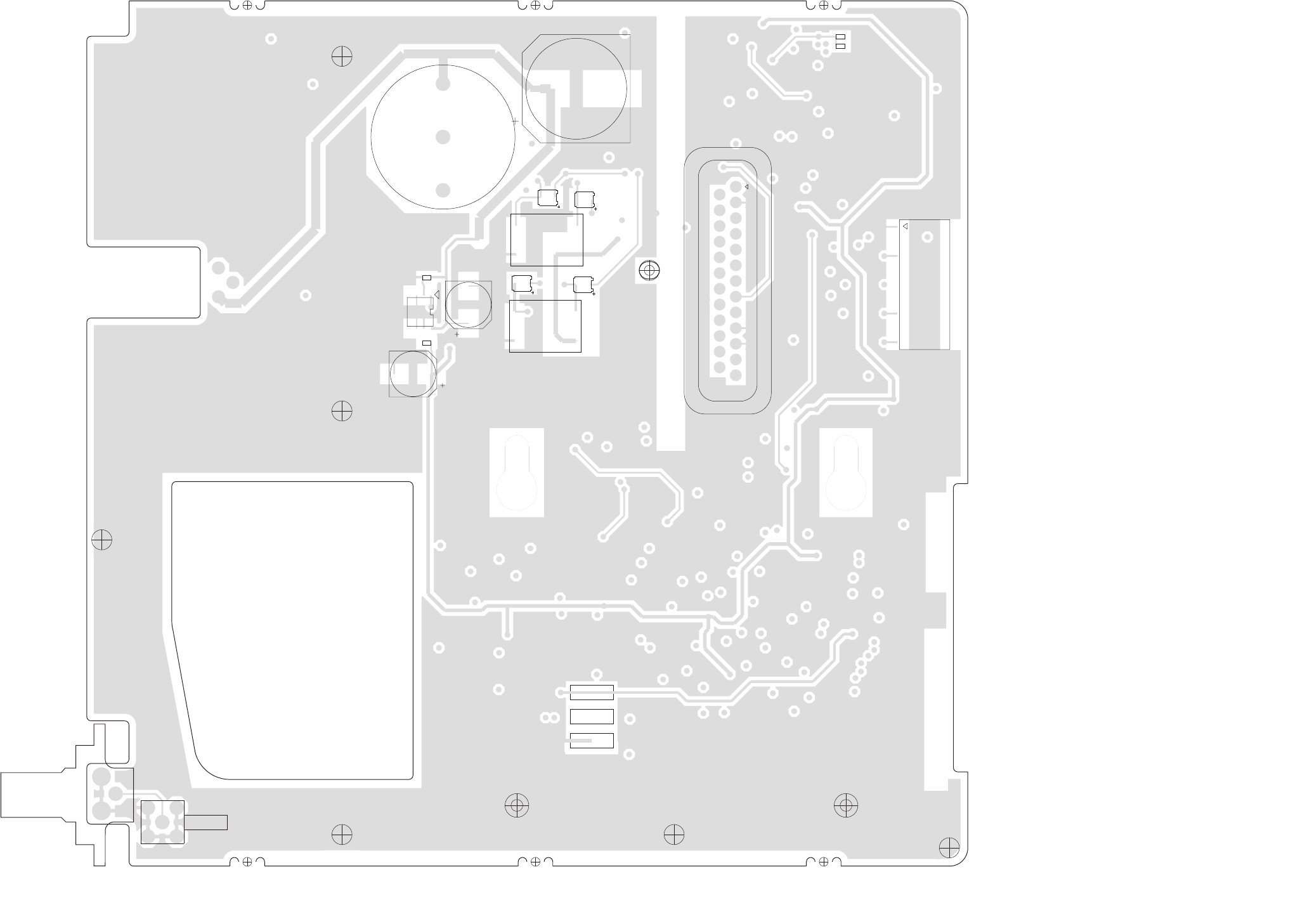
85
W102
8485176D01 REV A
C103
C132
C133
C137
C156
C157
C159
C162
C183
C195
C196
L101
P31
P32
P33
1810
9
P101
25 14
13
P102
1
3
46
T1
1
3
46
T2
45
8
U111
W101
VRS750 Vehicular Repeater System
Printed Circuit Board Component Location Diagram (Sheet 2 of 2)
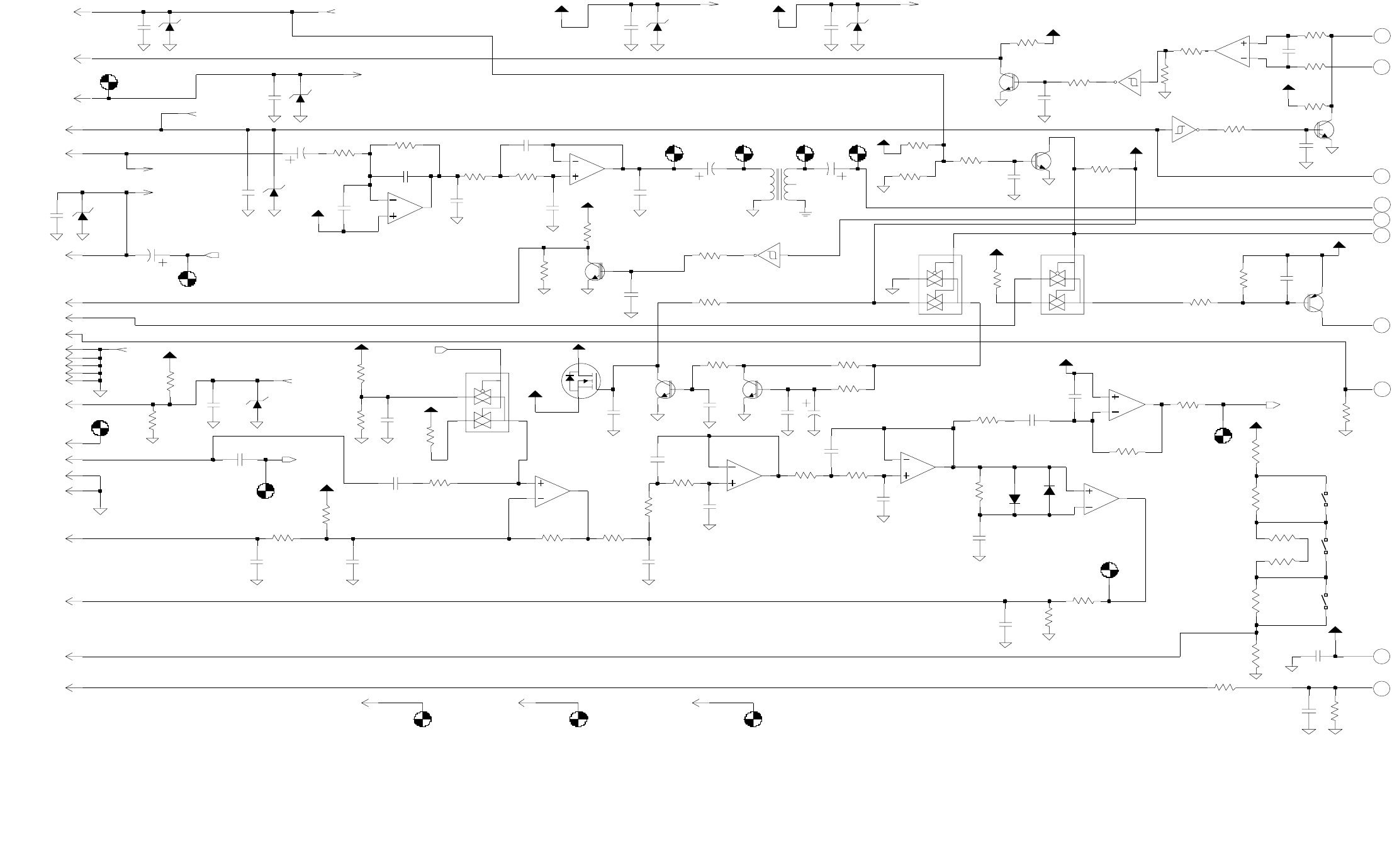
86
(J20-16)
URX_SND
(J20-1)
*
(J20-15)
(J40-29)
(J40-24)
(J20-4)
(J20-12)
(J40-28)
(J40-20)
(J40-2)
EXT_MIC
(J40-22)
(J20-10)
(J20-13)
(J20-19)
(J20-20)
(J20-9)
(J20-14)
(J20-8)
(J40-21)
(J20-7)
(J40-1)
(J40-25)
(J20-11)
(J40-13)
(J40-23)
DNP
.015uF
C117
3
1
U124-1
MC3303
2
J30 20
9.6V
C104
1uF
27K
5.6V
VR112
R122
J30 5
2
3
1
C119
0.22uF
33pF
U100-1
MC33072
1000pF
C145
C101
220pF
C205
C204
220pF
220pF
C203
220pF
C202
220pF
C206
U124-2
MC3303
6
5
7
1K
R217
J30 21
2
J30
4.7K
R166
10K
R102
220pF VR123
5.6V
P102-17
C207
P102-16
R118
4.7K
R171
1%
J30 17
27K
R111
47.5K
T1
1
34
5
6
P101-9
R114
330K
J30 1
J30 6
R175
VAG
10K
C188
220pF
TP112
R117
4.7K
R137
10K
25
J30
J30 4
5V
5.6V
VR121
10K
R225
MMBT3904
Q103
5.6V
VR102
8
R220
0
1000pF
U124-3
MC3303
9
10
16
C118
MMBT3904
Q112
J30
8
1
TP110
28
S1
J30
C146
220pF
Q111
MMBT3904
1000pF
C180
1uF
C189
TP111
C165
220pF
C111
220pF
220pF
C109
C113
R123
2200pF
27K
MC33072
U107-1
2
3
1R212
10K
J30 24
MMBT3904
Q110
TP113
220pF
C102
15K
R110
5.6V
VR113
R113
100K
22K
R221
10uF
C182
27K
R215
R107
6.8K
5V
100K
R224
C114
.01uF
D
G
S
4.7K
R213
J30 7
Q113
R174
27.4K
VR118
5.6V
VAG
1%
J30 22
J30 11
R172
10K
5V
C100
220pF
S1
6
3
100
22.1K
R130
1%
220pF R104
R127
10K
C161
220pF
C112
R156
J30 10
1K
R126
15K
C175
D100
220pF
R140
100K
4.7K
SW7.5V
R112
10K
R211
P101-1
1K
R210
4.7K
R200
TP101
J30 3
C122
220pF
U103-5
MC14106
1110
1uF
C103
100K
R109
6.8K
P102-3
J30 26
R119
C116
.01uF
U107-2
MC33072
6
5
7
0.1uF
Q104
MMBT3906
10K
C105
C107
R173
220pF
9.6V
R216
C194
1.5MEG
13
MC14053B
U102-3
9
4
5
3
1000pF
MC14053B
U102-2
11
14
12
220pF
C191
7.5V
P102-1
5V
0.1uF
C120
68K
P101-7
VR115
15V
R108
R105
R106
4.7K
U124-4
13
12
14
100
R139
1K
MC3303
10K
68K
R124
R101
U101-2
MC14053B 11
14
12
13
J30 12
J30 30
5V
9.6V
J30 8
J30 9
R128
100K
1%
TP104
R120
10K
R116
30K
4.7K
R138
5V
Q100
MMBT3904
R125
56K
J30 27
C164
220pF
SW7.5V
5V
7
2
MC14106
U103-3
56
J30 29
S1
R155
10K
10K
R136
10K
J30 23
P101-3
J30 19
R121
Q101
MMBT3904
C179
P102-4
220pF
C121
100pF
D101
TP103
MC14106
U103-2
34
1%
9.6V
.1uF
C108
100K
R131
75K
R115
TP123 TP124TP121 TP122
27.4K
R129
1%
C125
220pF
5V
5V
C183
1uF
TP120
U100-2
MC33072
6
5
7
C190
680pF
TP102
.01uF
5V
EXT_SPKR+
C115
TXD
SNGL_DET
TEST_MODE-IN
RSS TX_RX_AUDIO
PTT
VRS_TX*_RX
BUSYOUT
BOOT-CNTRL
RXD
SNGL_TX_DATA
TONES-MOBILE_AUD
RESET
BUSYIN
RX_FIL_AUD
PROG_SENSE
EXT_MIC
SNGL_OUT
A
B
C
D
E
F
G
H
I
J
VRS750 Vehicular Repeater System
Printed Circuit Board Schematic Diagram (Sheet 1 of 2)
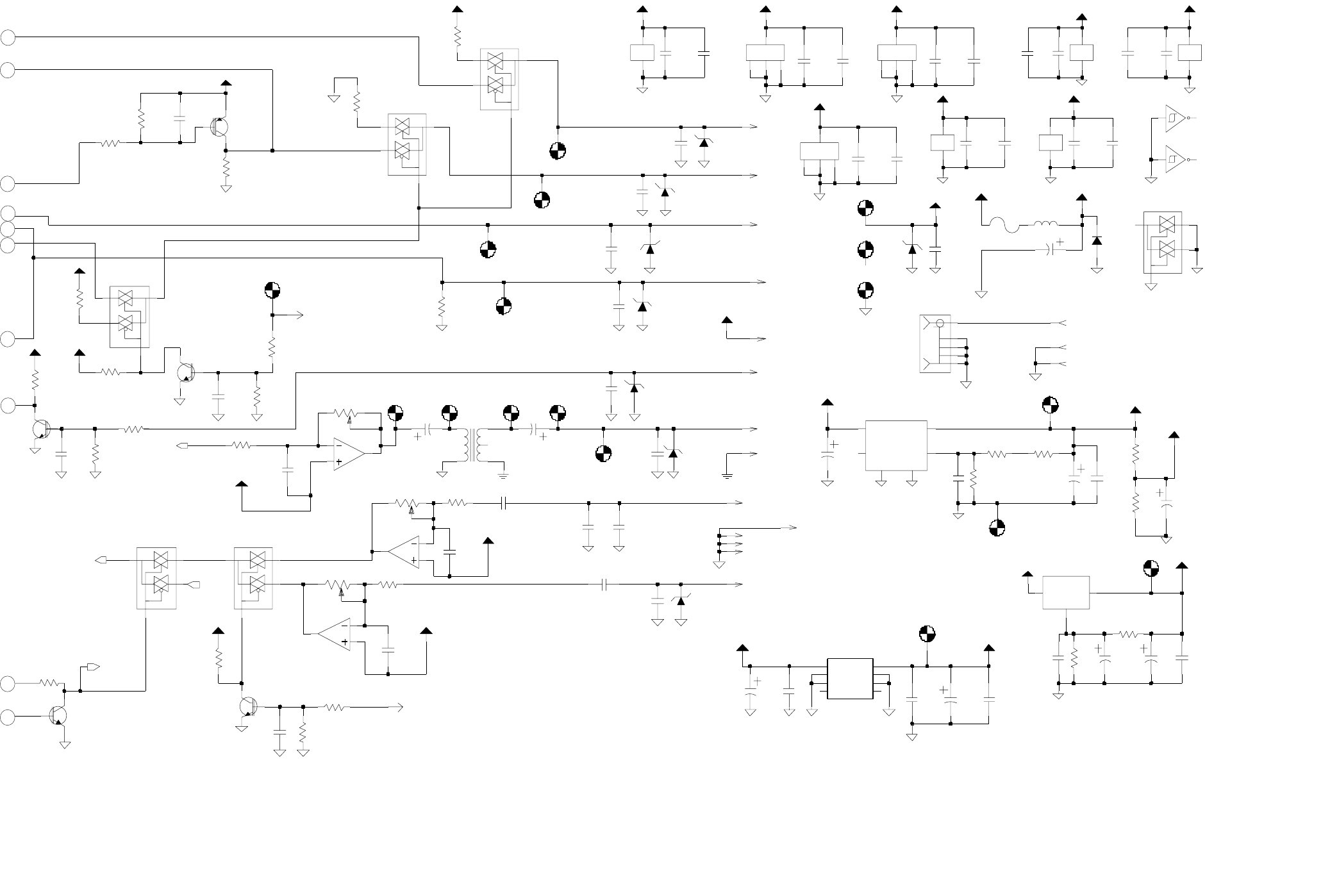
87
MOB_ANA_GND
P102 IS 25 PIN DB25 CONNECTOR
(J40-30)
AUX_RX_AUD
MOB_ANA_GND
P101 IS 18 PIN PROGRAMMING CONNECTOR
FIL_AUD
CONNECTIONS
TO TRANSCEIVER
DGND
R226
4.7K
8
4
MC14106
U103-6
13 12
U107
SWB+
C150
220pF
C170
220pF
C139
220pF
W102 1
P102-5
7.5V
D102
4.7K
R132
220pF
C201
220pF
C200
0.1uF
0.1uF
C199
C197
220pF
C198
220pF
C127
9.6V
Q106
MMBT3904
220pF
C152
220pF
C167
10K
R163
U101-3
MC14053B
9
4
5
3
R229
10K
R228
10K
220pF
C208
9.6V
MMBT3904
Q115
R227
4.7K
F100
12
VAG
U103-1
MC14106
C195
0.1uF
C196
5V
220pF
TP108
9
10
8
C124
220pF
U101-4
16
678
U104-3
MC3303
R180
4.7K
100uF
C156
C137
2200uF
TP114
5.6V
VR108
Q109
MMBT3904
1.8K
R159
P102-2
C126
220pF
C166
220pF
10K
R164
C132
1uF
P102-18
1000uH
L101
P102-10
4.7K
R133
9
4
5
3
MC14053B
U105-3
P102-23
P102-22
220pF
P102-12
C128
C157
220pF
360
R158
C155
10uF
R142
1K
C151
10uF
OUT 1
SHDN*
4
TAB
6
U102-1
MC14053B
10
15
2
1
U118
LT1129CQ
ADJ 2
GND
3
IN
5
SWB+
R141
4.7K
C173
4.7K
220pF
R147
VAG
1uF
C148
C133
C130
VAG
P102-8
1uF
4
11
220pF
U104-5
220pF
C160
C162
100uF
TP109
10uF
C153
TP116
C123
220pF
5.6V
U129
ADJ
IN OUT
P102-7
VR105
C136
220pF
W102 3
U124-5
4
11
15K
R157
U102-4
16
678
P102-21
C129
220pF
U104-4
MC3303
13
12
14
5V
.1uF
C143
R160
15K
5V
RADIO_SWB+
TP117
220pF
C147
2K
R165
VAG
C158
220pF
C140
0.1uF
U104-1
MC3303
2
3
1
4
5
6
9.6V
T2
1
3
5V
SW7.5V
R161
220pF
C159
C149
10uF
820
220pF
.01uF
5V
C131
C141
56K
R149
47K
R145
U100
POWER POWER POWER POWER
POWERPOWER
POWER
POWER
8
4
W101
2
3
4
5
1
P102-19
20K
R150
J30 13
P102-6
C142
5.6V
VR107
9.6V
220pF
TP119
220pF
9.6V
C138
VR104
5.6V
VR106
5.6V
220pF
C184
R183
10K
9.6V
R182
1K
0.1uF
C135
9.6V
R146
20K
9.6V
P102-11
5.6V
VR103
C185
.047uF
100K
5.6V
VR109
R151
2
1
10K
R162
MC14053B
U101-1
10
15
0.1uF
C171
J30 15
TP106
9.6V
C172
220pF
R148
20K
U105-4
16
678
TP118
MMBT3906
Q102
14
7
VR110
15V
U103-7
P33
4.7K
R143
TP105
NC 4
NC1
5
8VIN VOUT 1
U111
GND 2
GND1 3
GND2
7
GND3
6
0.1uF
C134
P32
0.1uF
C168
TP127 TP128TP125 TP126
9.6V
220pF
C154
9.6V
MC14053B
U105-1
10
15
2
1
11
14
12
13
4.7K
R181
U105-2
MC14053B
R184
4.7K
W102 2
MMBT3904
Q114
P31
P102-14
TP107
RADIO_SWB+
SWB+
SWB+
MIC_FIL_SEL
BUSY
RX_FIL_AUD
BUS+
BUS-
MOBILE_MIC_HI
RADIO_RESET
TX_AUDIO
SNGL_OUT
EXT_MIC
VRS_TX*_RX
LM317
A
B
C
D
E
F
G
H
I
J
VRS750 Vehicular Repeater System
Printed Circuit Board Schematic Diagram (Sheet 2 of 2)
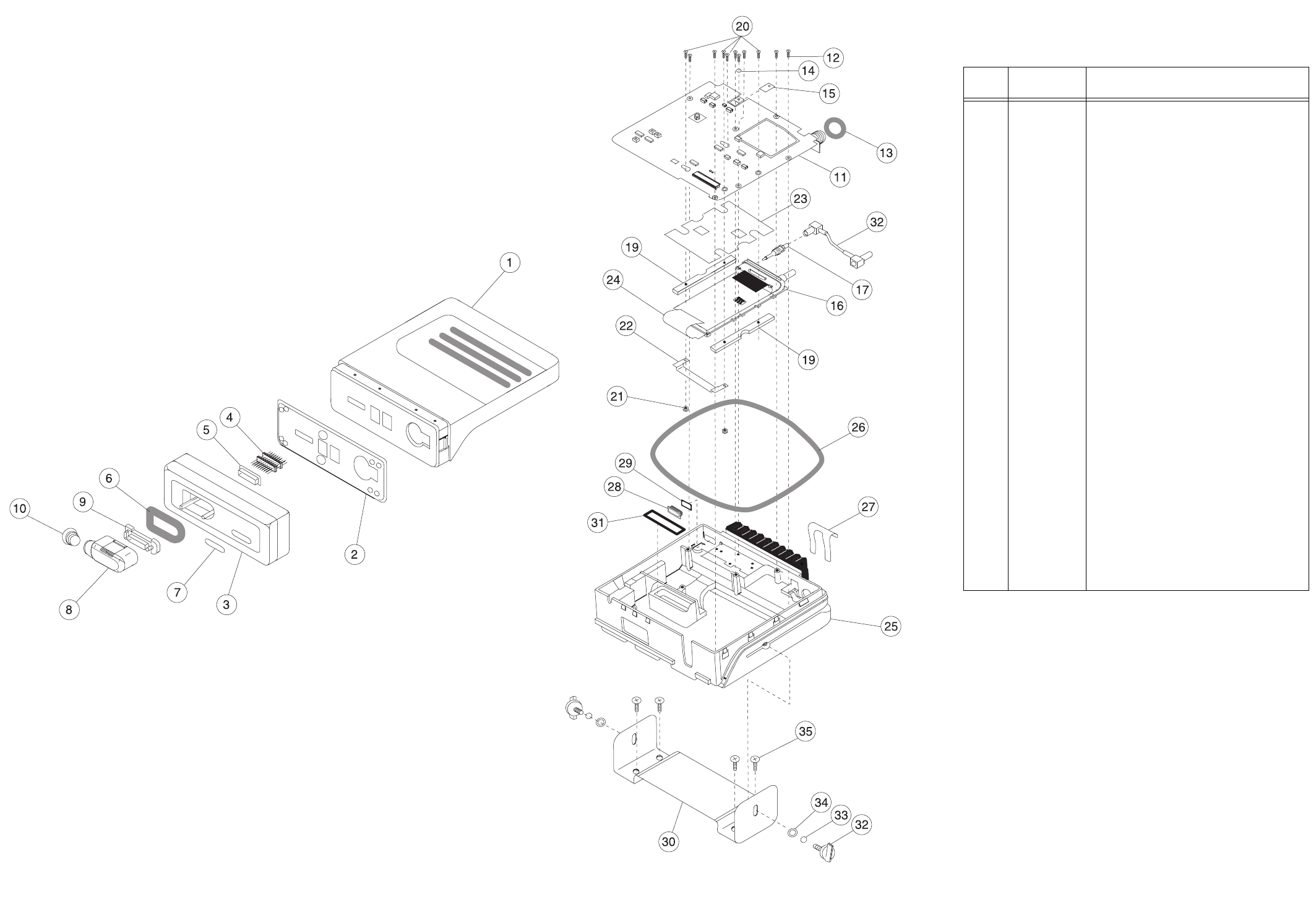
88
VRS750 Vehicular Repeater System
Exploded View Parts List
ITEM
NO.
MOTOROLA
PART NUMBER DESCRIPTION
1 1505764X01 COVER ASSEMBLY, Midpwr Top
2 3205931V02 GASKET, Front Cover
3 1505905V02 HOUSING, Remote Front
4 2805347X01 CONNECTOR, 18 Position
5 4205395X01 RETAINER, Programming Connector
6 3205789X01 GASKET, Remote Cable
7 3385950D01 LABEL, Front
8 1505784W01 HOUSING, Programming Connector
9 1505791W01 HOUSING, Programming Connector Terminal
10 3285803D01 PLUG, Programming Connector
11 PLN7780A VRS750 Controller Board
12 0310907A20 SCREW, M3 x .5 x 10 (8 req’d)
13 320545Z03 GASKET, Antenna Connector
14 0410057A13 WASHER, Nylon (for Regulator)
15 1483820M02 INSULATOR, Nylon, Heat Conductive
(for Regulator)
16 TRANSCEIVER
PMLD4196A VHF Transceiver
PMLE4242A UHF R1 Transceiver
PMLE4243A UHF R2 Transceiver
17 2885170D01 PLUG, RF Phone to SMB
18 3085166D01 CABLE, RF Coax
19 4285033D01 RETAINER, Internal Radio (2 req’d)
20 0300139800 SCREW, 6-32 x .5
21 0200844628 NUT, 6-32
22 4285168D01 RETAINER, Flex Connector
23 1485171D01 INSULATOR, PC Board
24 8485177D01 CABLE, Flex
25 2785032D01 CHASSIS, Modified
26 3205934V01 GASKET, Casting
27 4205938V01 CLIP, Spring
28 3885558D01 PLUG, Plastic DC
29 3285169D01 SEAL, Power
30 0785588D01 BRACKET, Sp. Mounting
31 3205935V01 GASKET, 25-Pin Connector
32 0305760W02 SCREW, M5 x 0.8 x 12 (2 req’d)
33 0400135783 WASHER, Lk. Splt. (2 req’d)
34 0490440S01 WASHER, Flat (2 req’d)
35 0312002B14 SCREW, 10-16 x 1 (4 req’d)
VRS750 Vehicular Repeater System
Exploded View and Exploded View Parts List

89
VRS-to-Mobile Cable HKN6153A
Pin Number
Signal Name
VRS750
P102
ASTRO Spectra
Mobile DB25
Female
1 N/C
2 2 FIL_Audio_GND
3 N/C
4 N/C
5 5 Bus+
6 6 FLT_Audio
7 7 Rx_Audio
8 8 Tx_Audio
9 N/C
10 10 AGND
11 11 Mic_Lo
12 12 Mic_Hi
13 N/C
14 14 Bus-
15 N/C
16 N/C
17 N/C
18 18 DGND
19 19 Reset
20 N/C
21 21 Bus_GND
22 22 SWB+
23 23 Busy
24 N/C
25 N/C
VRS-to-Siren Cable HKN6154A
Pin Number
Signal Name
VRS750
P102
Siren
(HLN1439A)
39 pin J1
1 N/C
2 15 FIL_Audio_GND
3 N/C
4 N/C
5 17 Bus+
6 9 FLT_Audio
7 33 Rx_Audio
8 3 Tx_Audio
9 N/C
10 11 AGND
11 14 Mic_Lo
12 27 Mic_Hi
13 N/C
14 25 Bus-
15 N/C
16 N/C
17 N/C
18 19 DGND
19 4 Reset
20 N/C
21 18 Bus_GND
22 6 SWB+
23 5 Busy
24 N/C
25 N/C
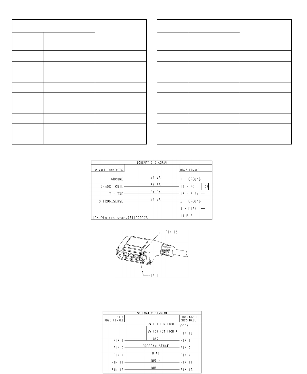
90
VRS750 Programming Cable 3085031D01
Pin Number
Signal Name
VRS750
P101
SRIB DB25
Female
1 1 Ground
2 N/C
3 16 Boot_Cntl
4 N/C
5 N/C
6 N/C
7 15 TXD
8 N/C
9 2 Prog_Sense
10 N/C
11 N/C
12 N/C
13 N/C
14 N/C
15 N/C
16 N/C
17 N/C
18 N/C
VRS750 Programming Cable 3085031D01
Pin Number
Signal Name
VRS750
P101
SRIB DB25
Female
VRS750 Programming Cable 3085031D01
VRS750 Programming Cable Schematic (3085031D01)
VRS750 Flashing Adapter Schematic (NTN4056A)

91
REPLACEMENT PARTS ORDERING
ORDERING INFORMATION
MAIL ORDERS
Send written orders to the following addresses:
TELEPHONE ORDERS
United States and Canada Accessories and Aftermarket Division: Servicers Training (VHS Video Tapes):
Call: 1-800-422-4210 Call: 847-576-2828
1-800-826-1913 (For Federal Government Orders)
1-847-538-8023 (International Orders)
FAX ORDERS
United States and Canada Accessories and Aftermarket Division: Federal Government Orders:
FAX: 847-538-8198 (Domestic) FAX: 410-712-4991
847-576-3023 (International) International: 410-712-6200
Parts ID: 847-538-8194
PARTS CUSTOMER SERVICE PRODUCT CUSTOMER SERVICE
When ordering replacement parts or equipment
information, the complete identification number
should be included. This applies to all components,
kits, and chassis. If the component part number is
not known, the order should include the number of
the chassis or kit of which it is a part, and sufficient
description of the desired component to identify it.
Crystal and channel element orders should specify
the crystal type or channel element type number,
crystal and carrier frequency, and the model
number in which the part is used.
Replacement Parts/
Test Equipment/Manuals/
Crystal Service Items:
Motorola Inc.
United States and Canada
Accessories and Aftermarket
Division
Attention: Order Processing
1313 E. Algonquin Road
Schaumburg, IL 60196
Federal Government Orders:
Motorola Inc.
United States and Canada
Accessories and Aftermarket
Division
Attention: Order Processing
7230 Parkway Drive
Landover, MD 21076
International Orders:
Motorola Inc.
United States and Canada
Accessories and Aftermarket
Division
Attention: International Order
Processing
1313 E. Algonquin Road
Schaumburg, IL 60196
United States and Canada Accessories and
Aftermarket Division:
Call: 1-800-422-4210
Parts Identification:
Call: 847-538-0021
Customer Resource Product Support
(Sales and Service Assistance):
Call: 1-800-927-2744
FAX: 1-954-723-4800

72
Motorola
8000 West Sunrise Boulevard
Fort Lauderdale, Florida 33322
6881094C84