Motorola Solutions 92FT3826 Mobile 2-Way Radio User Manual Installation Manual
Motorola Solutions, Inc. Mobile 2-Way Radio Installation Manual
UserManual.wiki
>
Motorola Solutions
>
92FT3826 User Manual
>
Installation Manual
Contents
1.
Ex 8 User Guide
2.
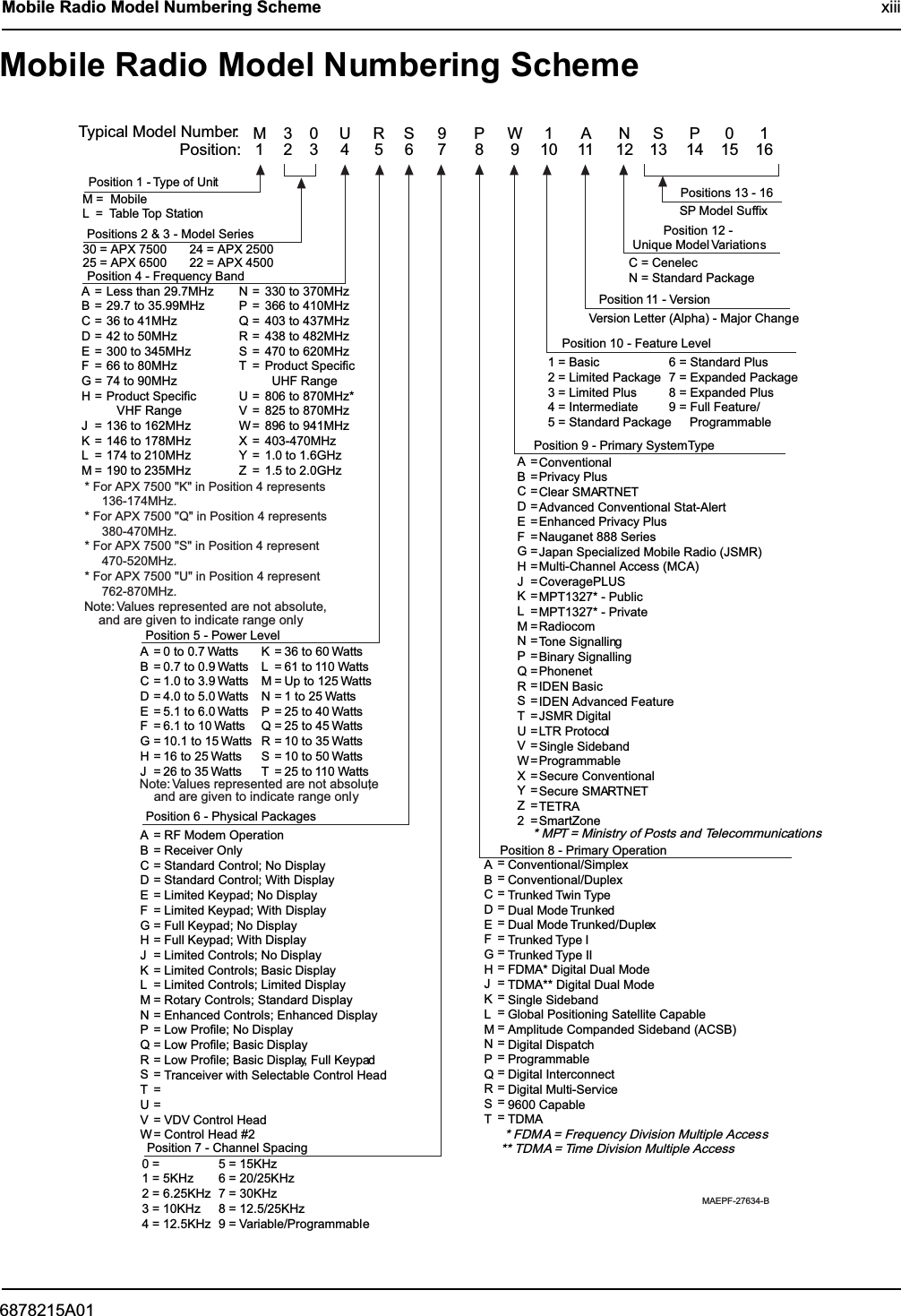
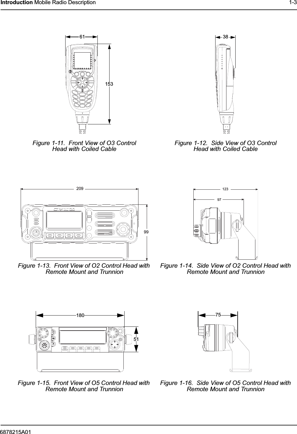
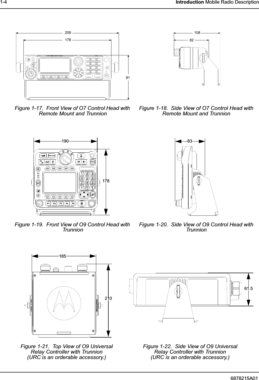
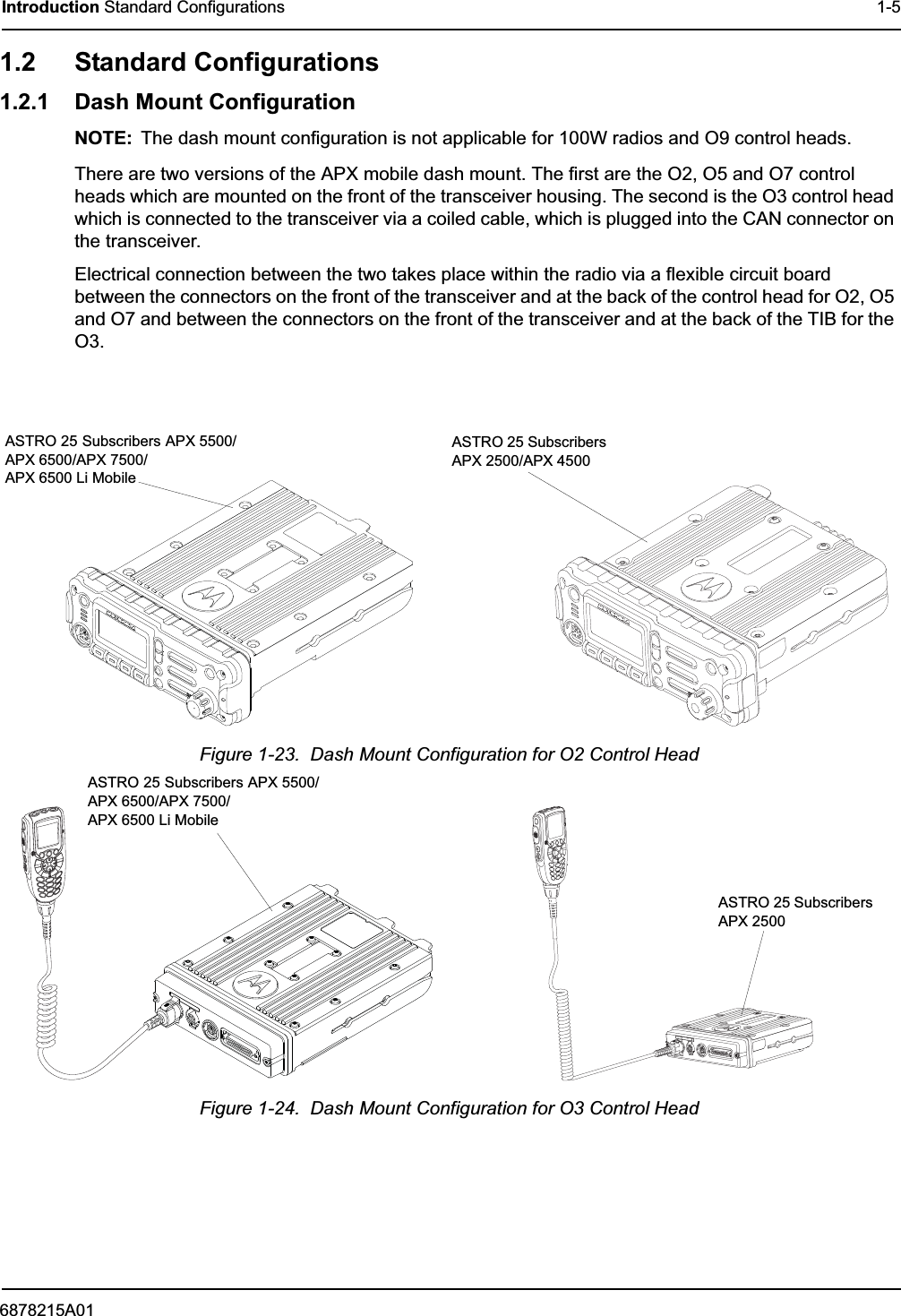
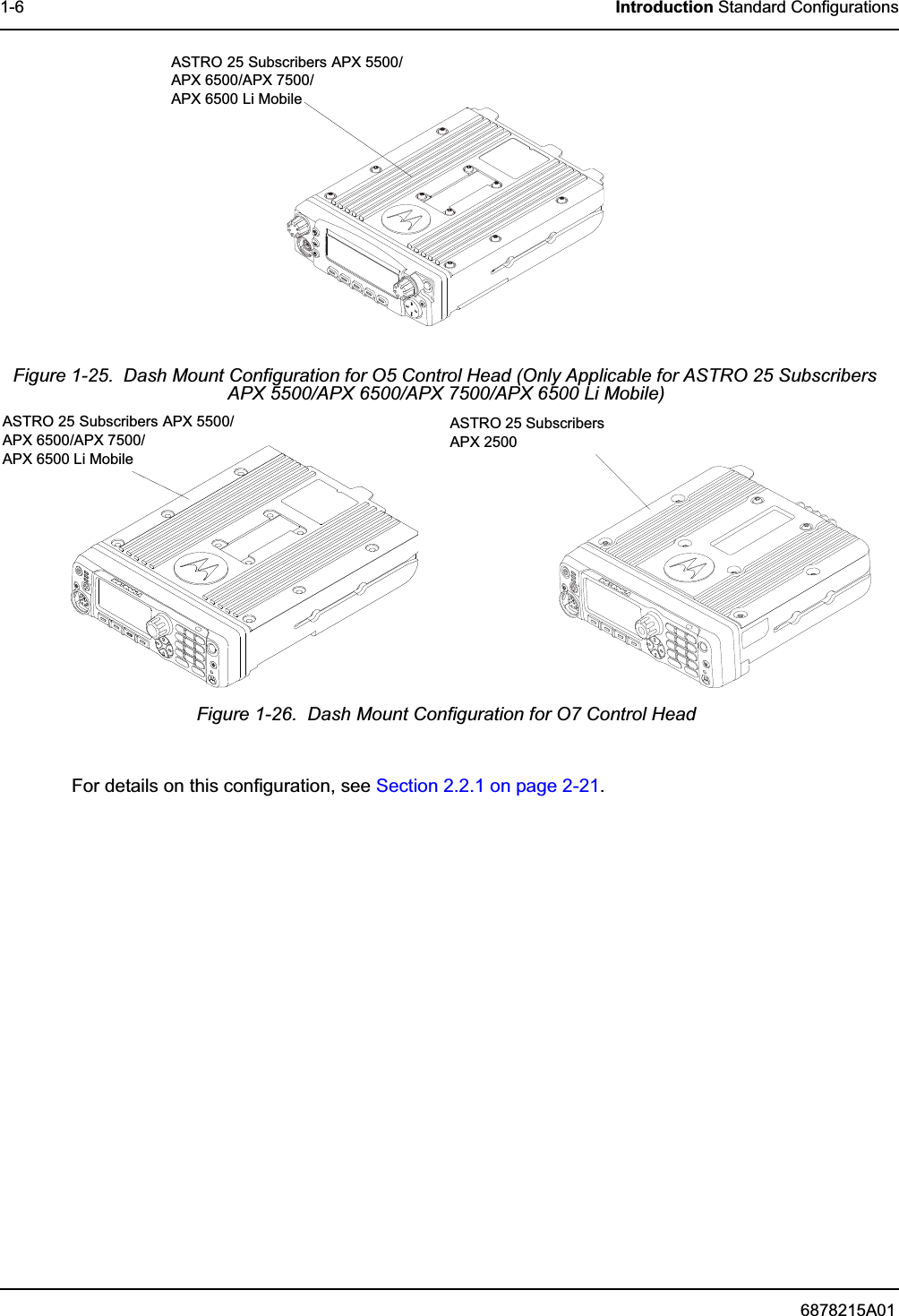
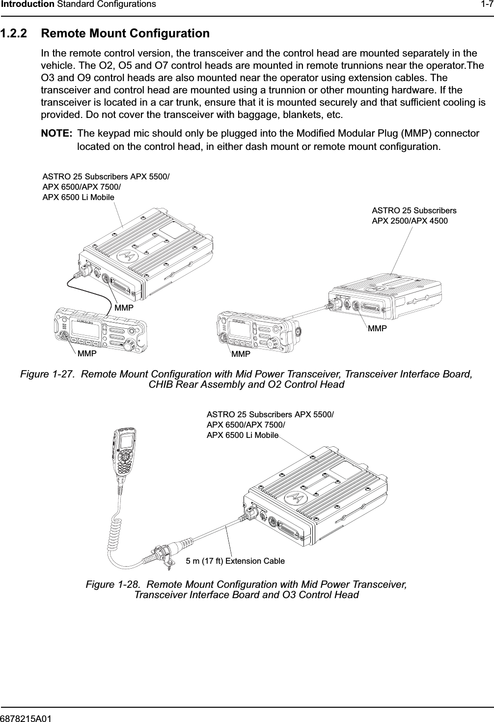
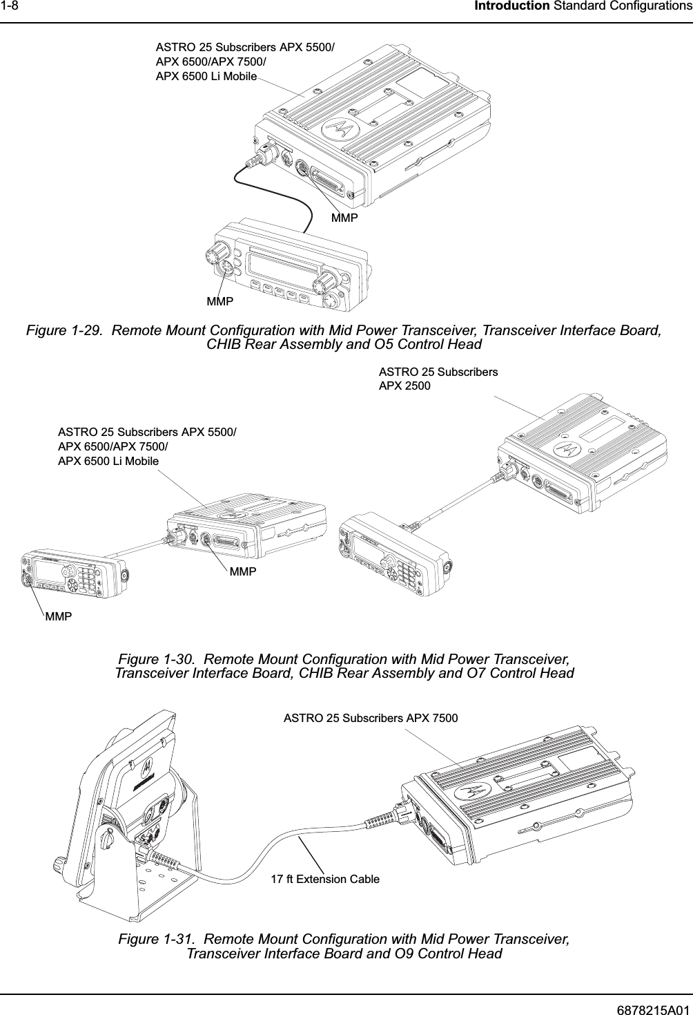
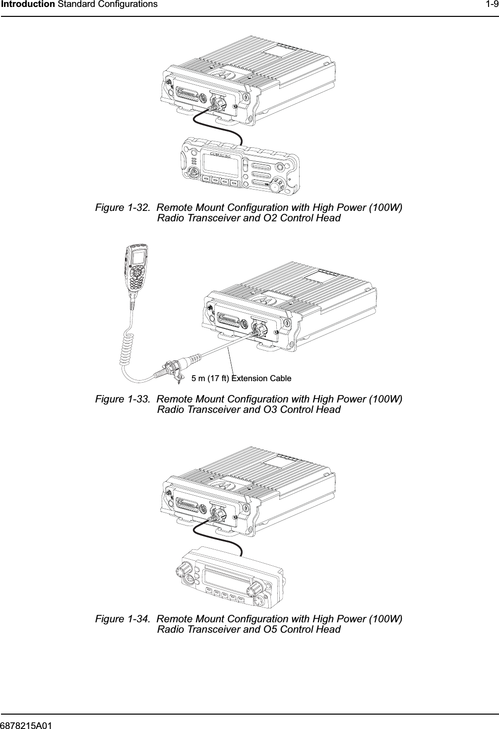
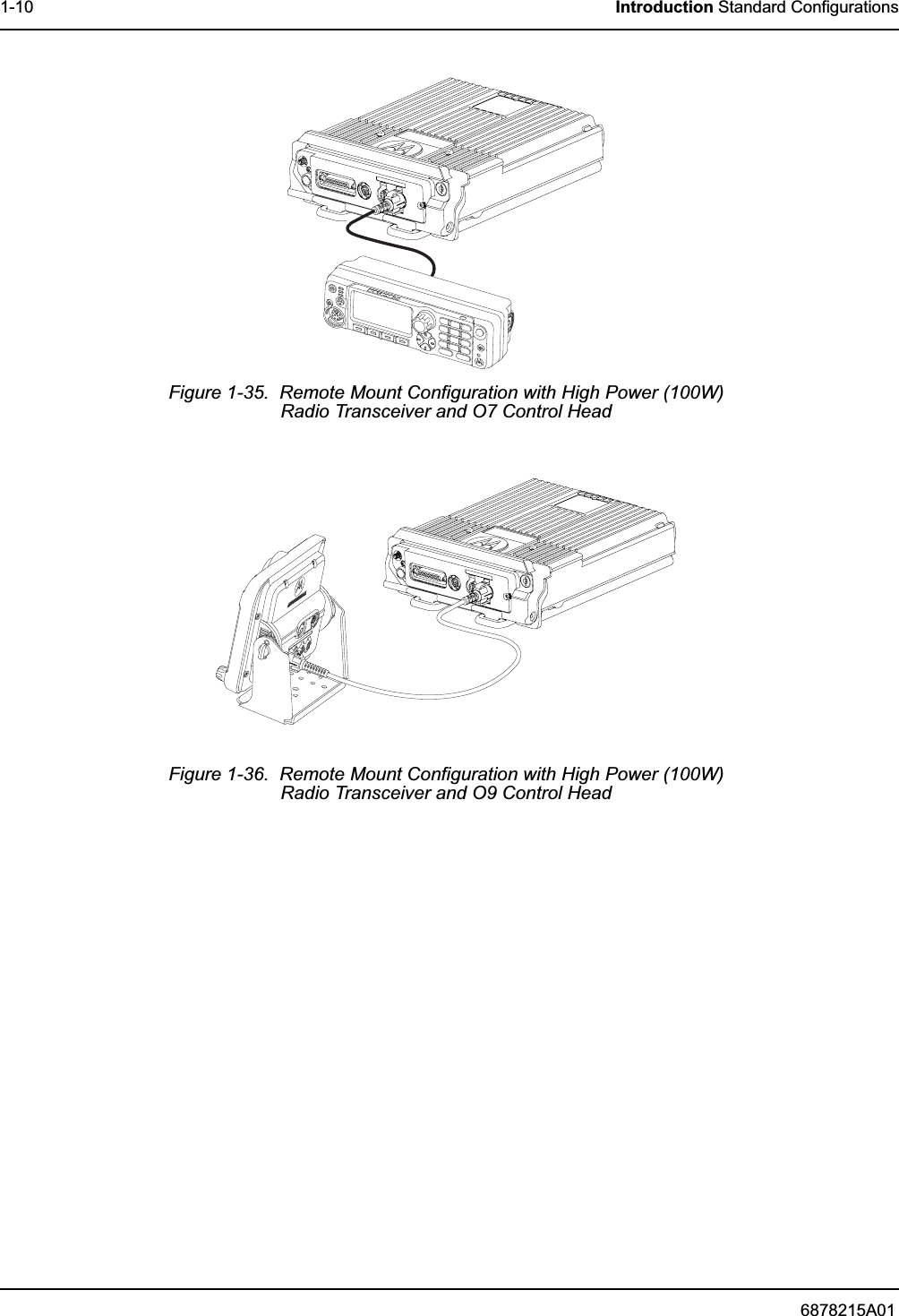
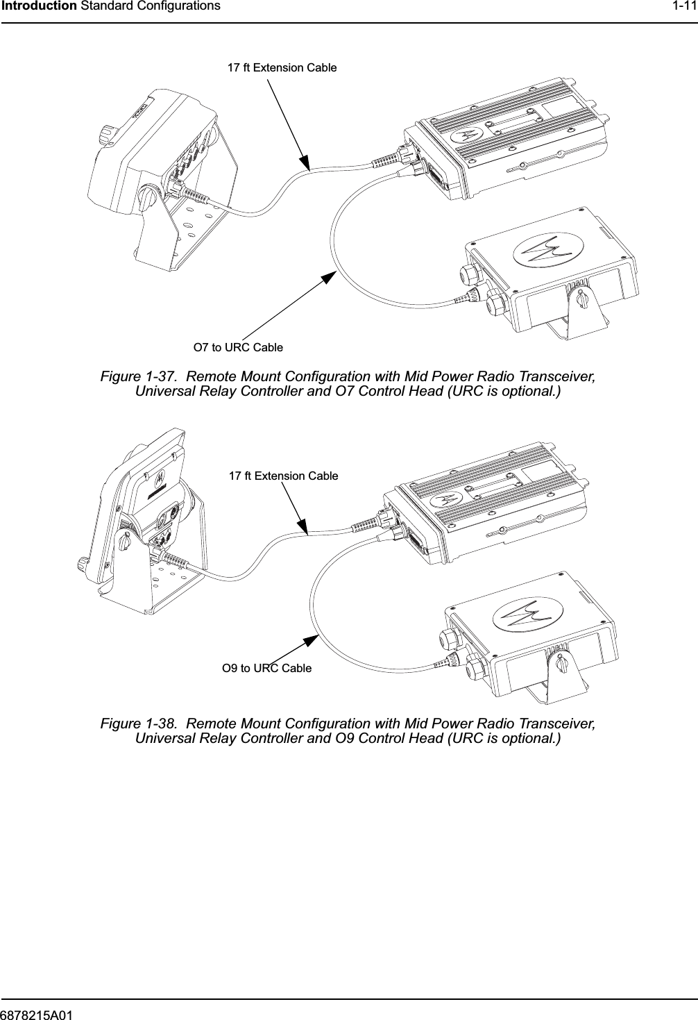
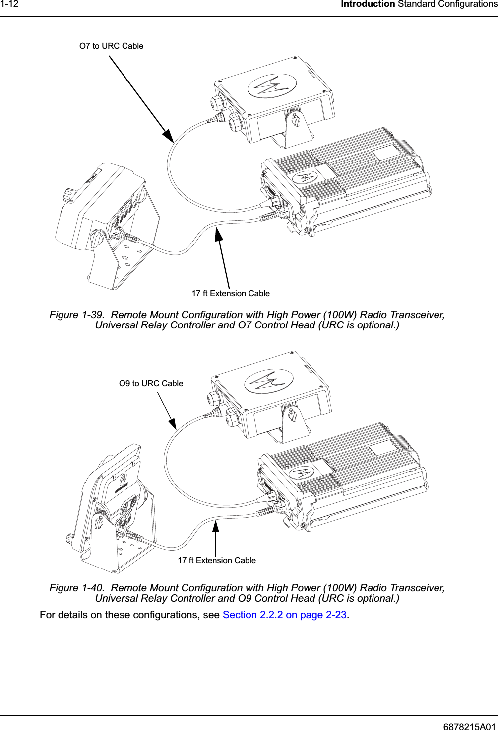
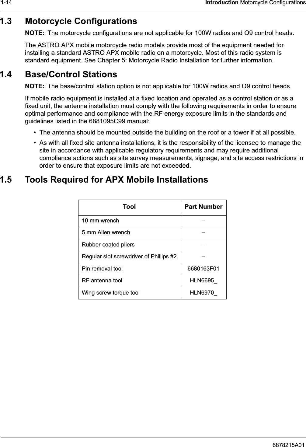
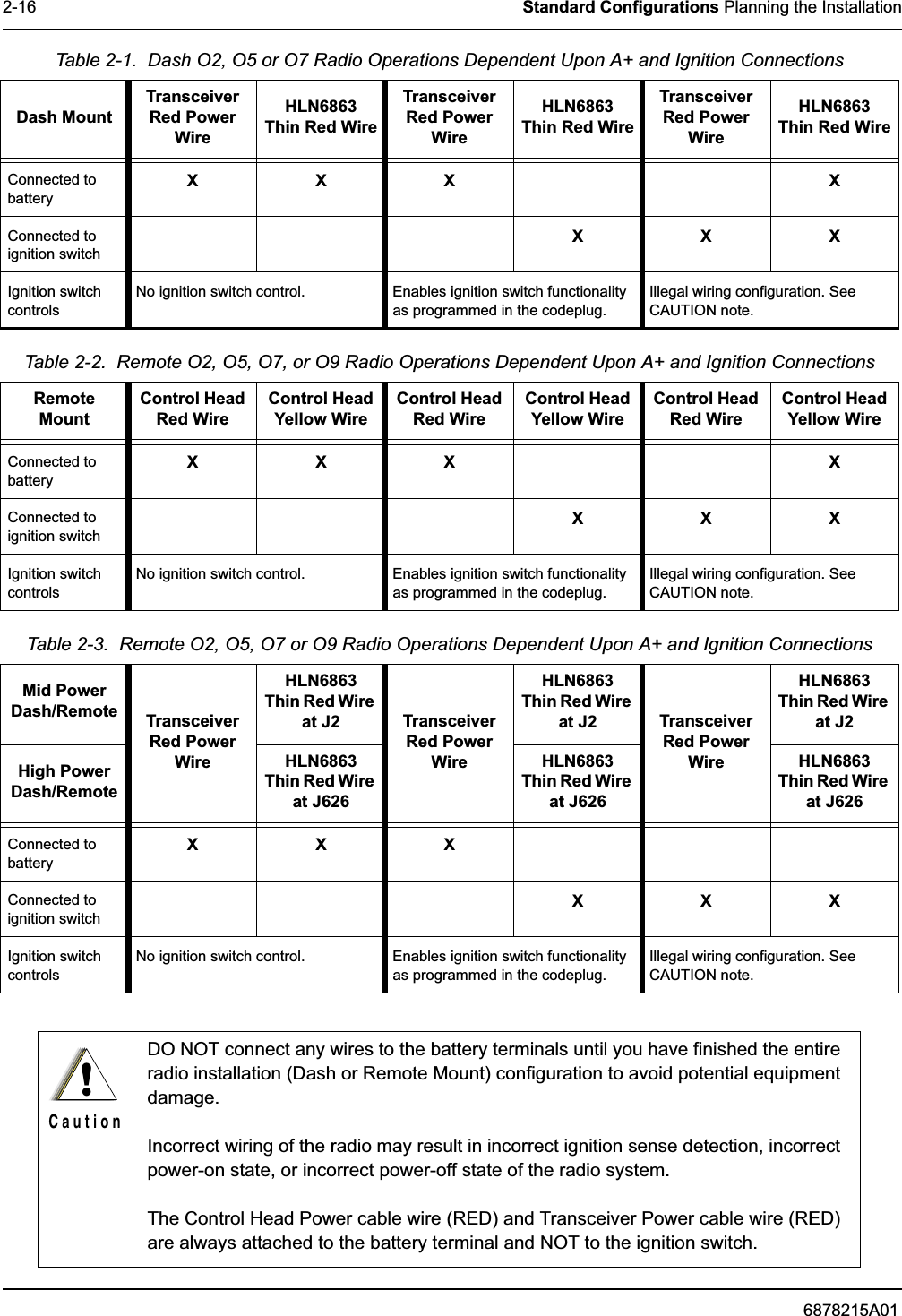
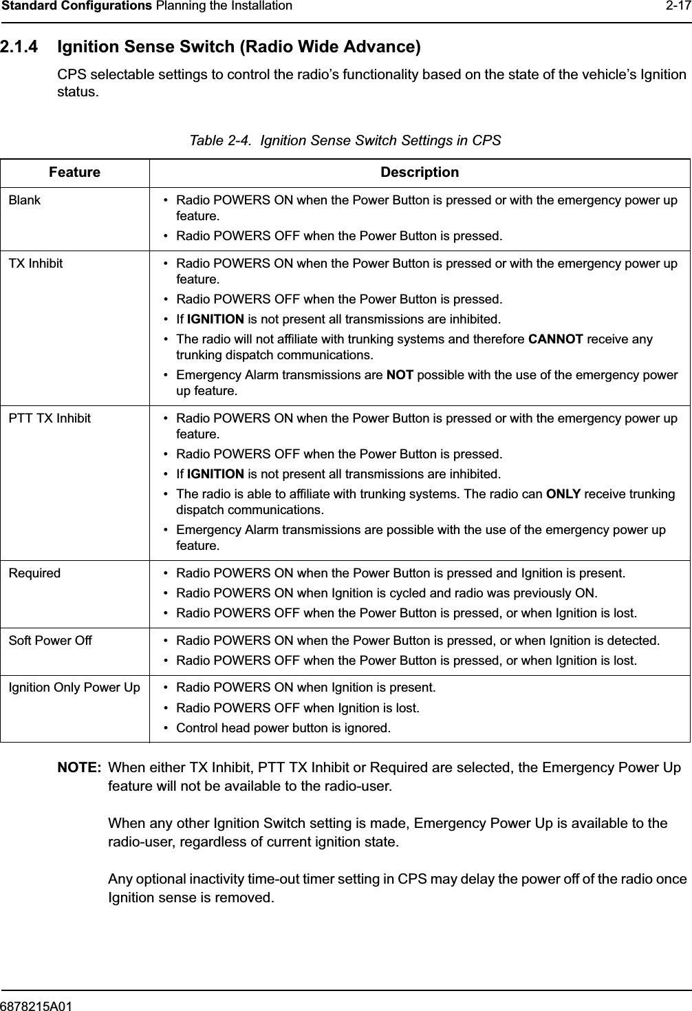
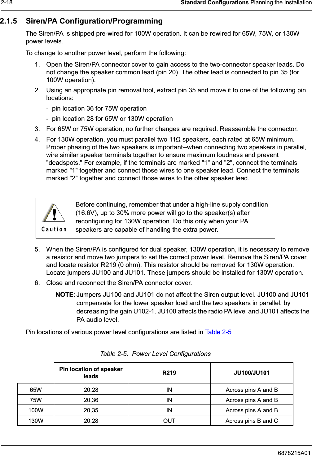
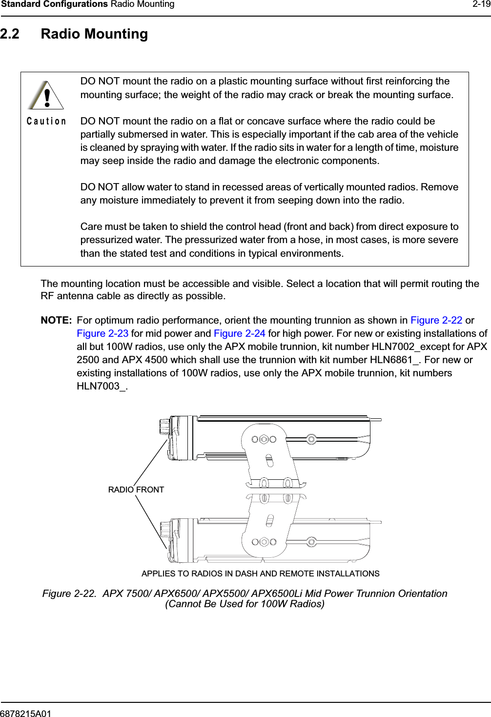
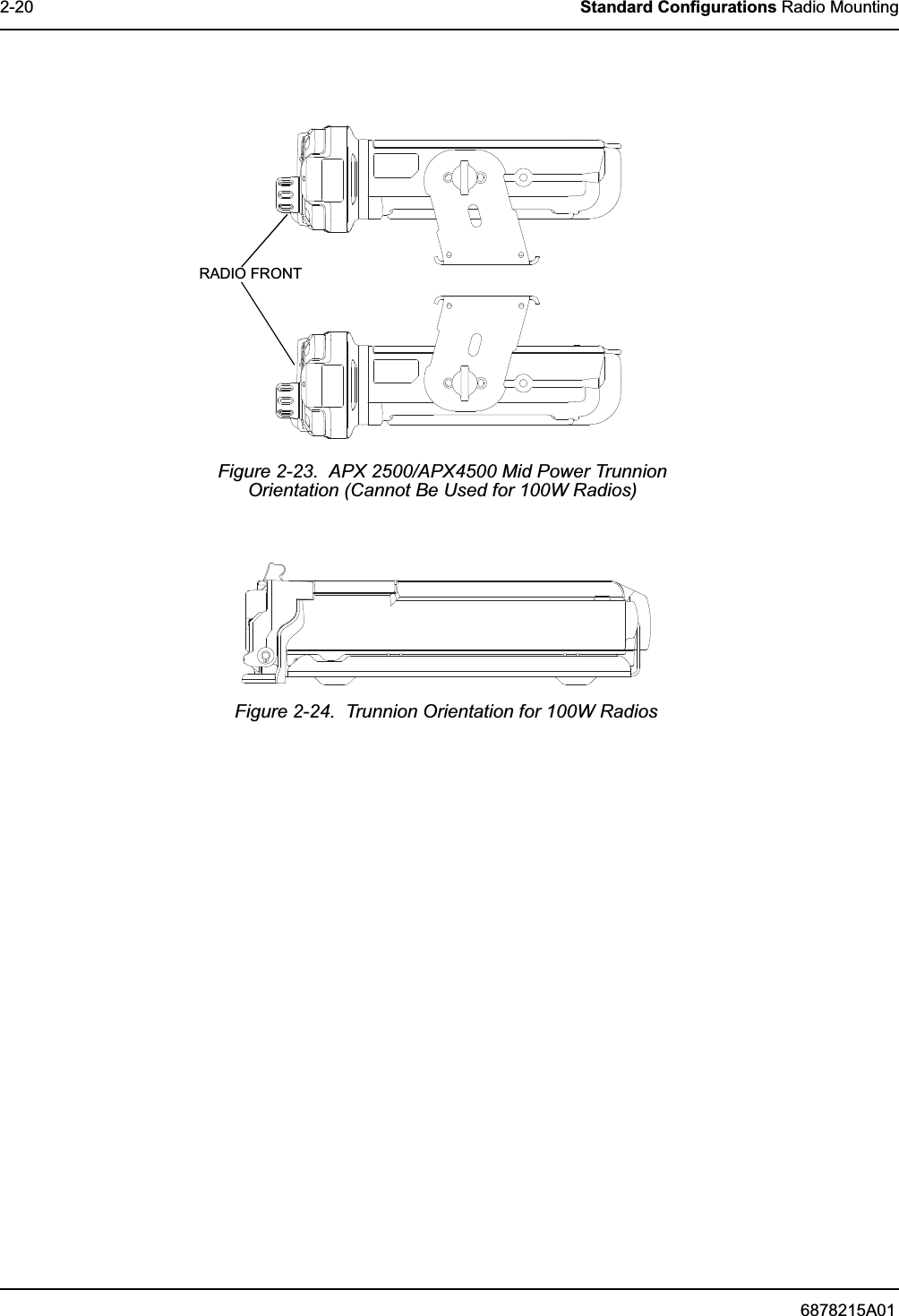
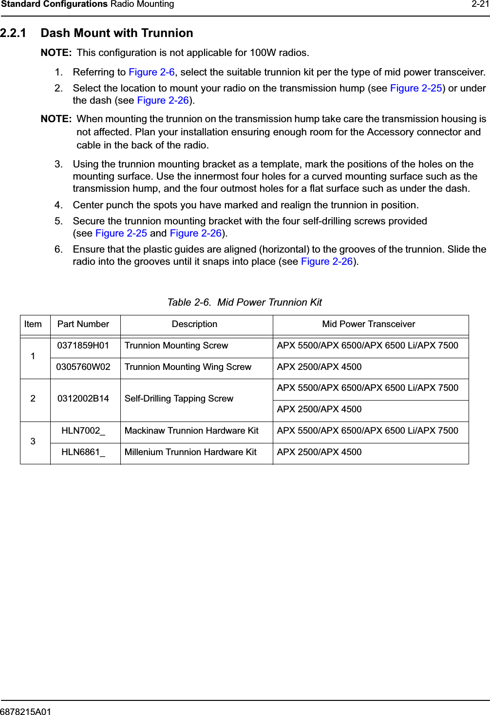
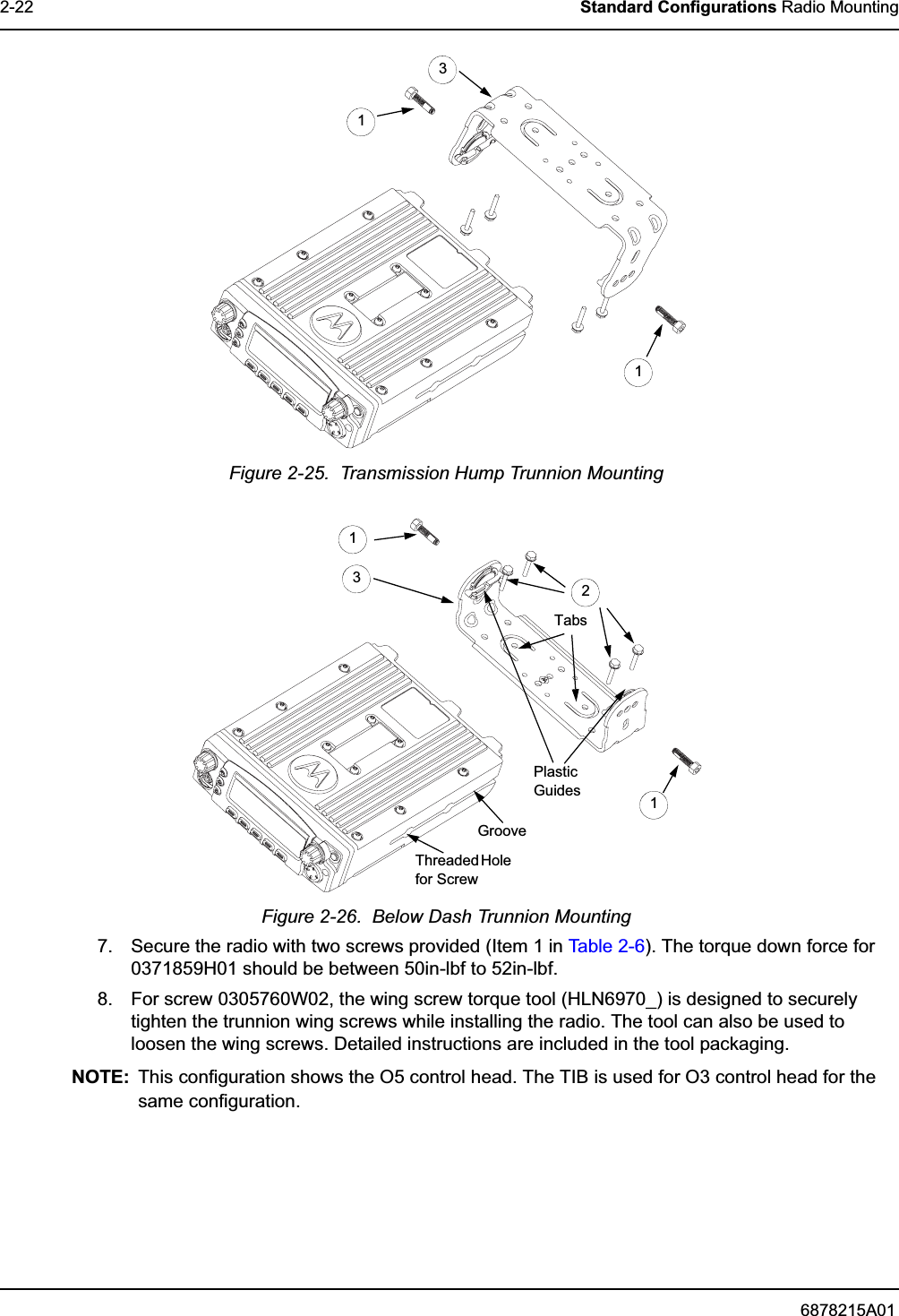
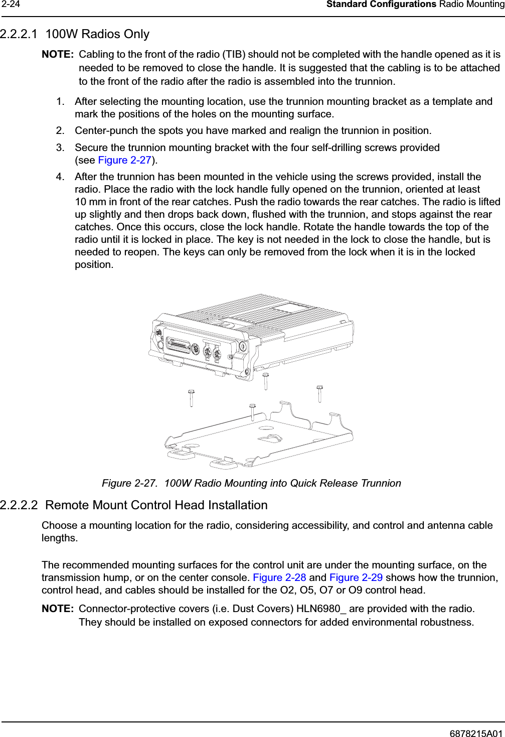
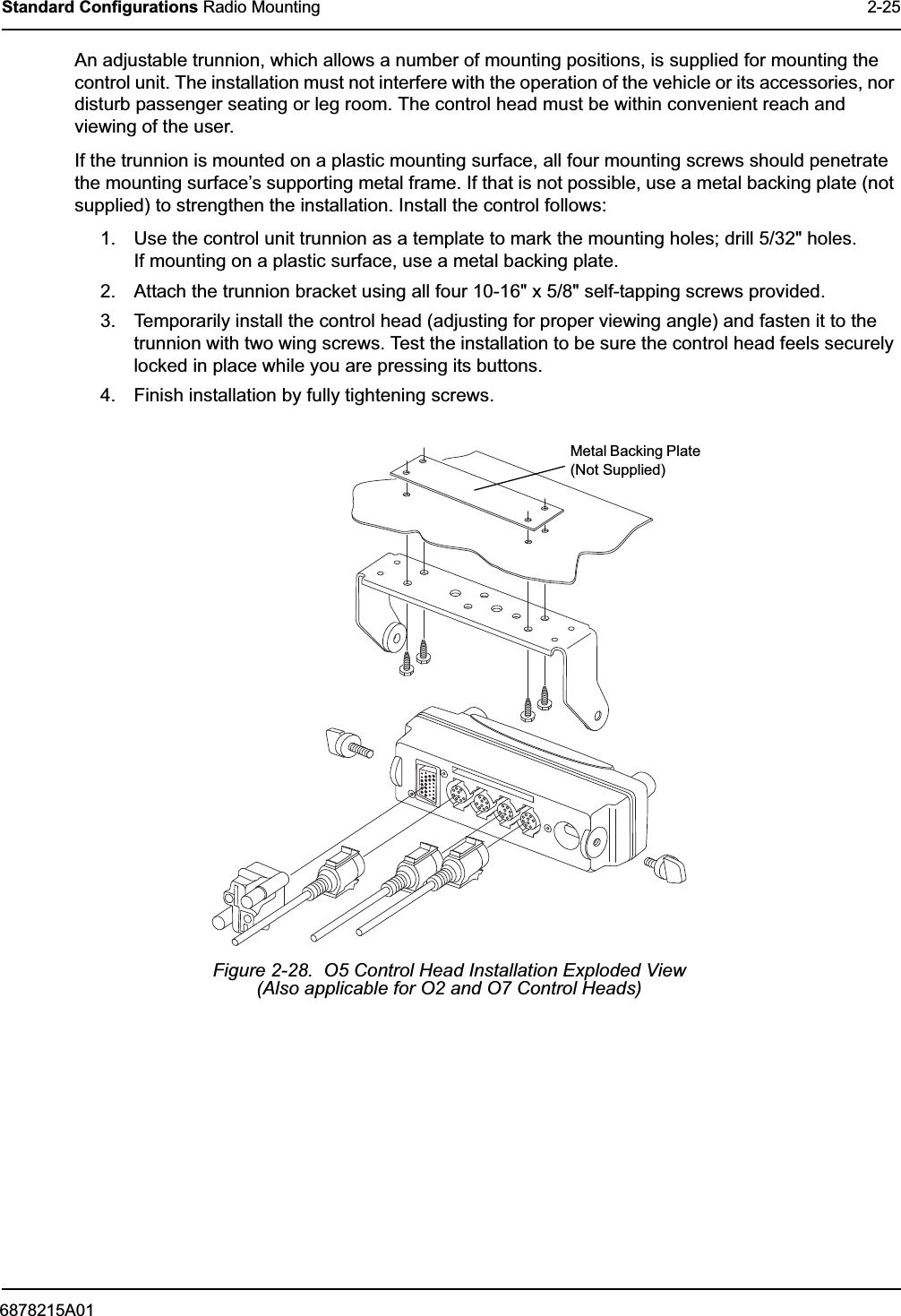
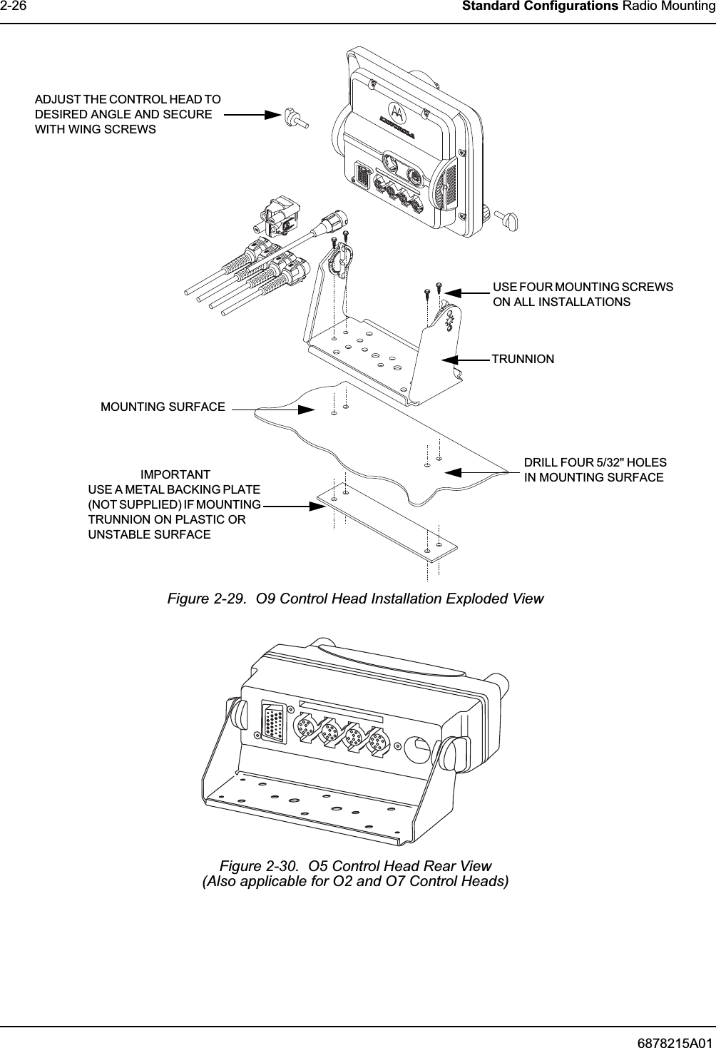
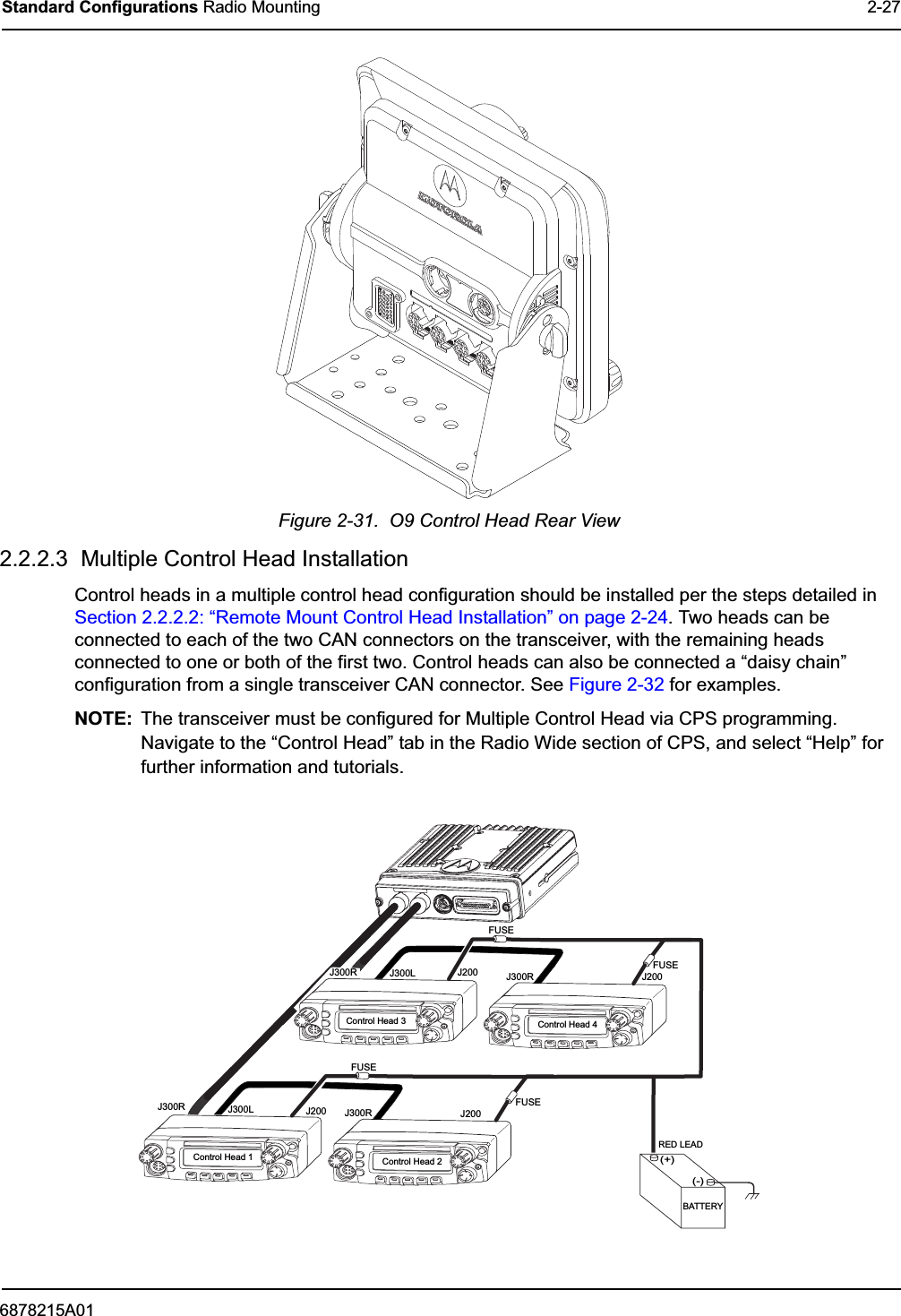
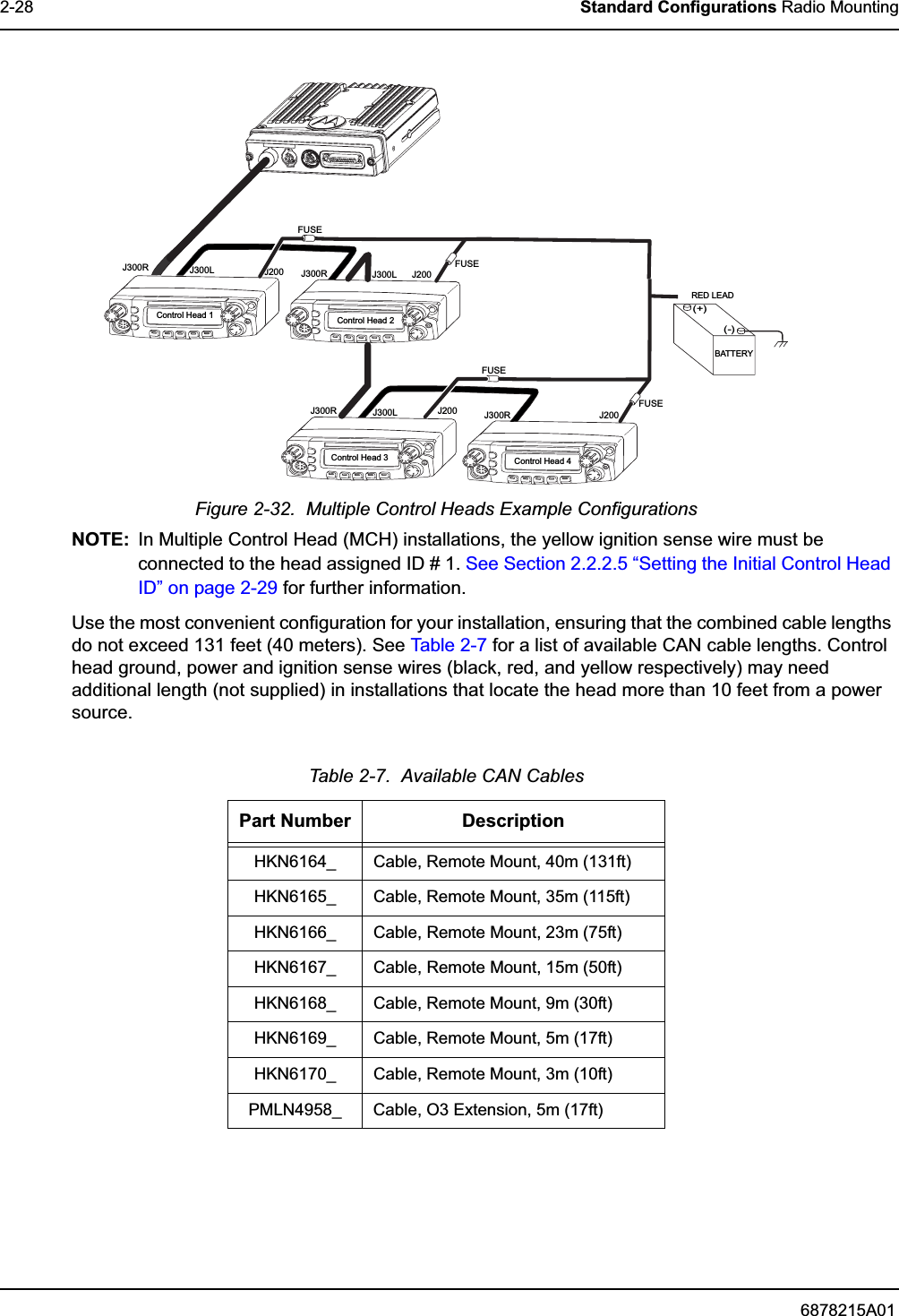
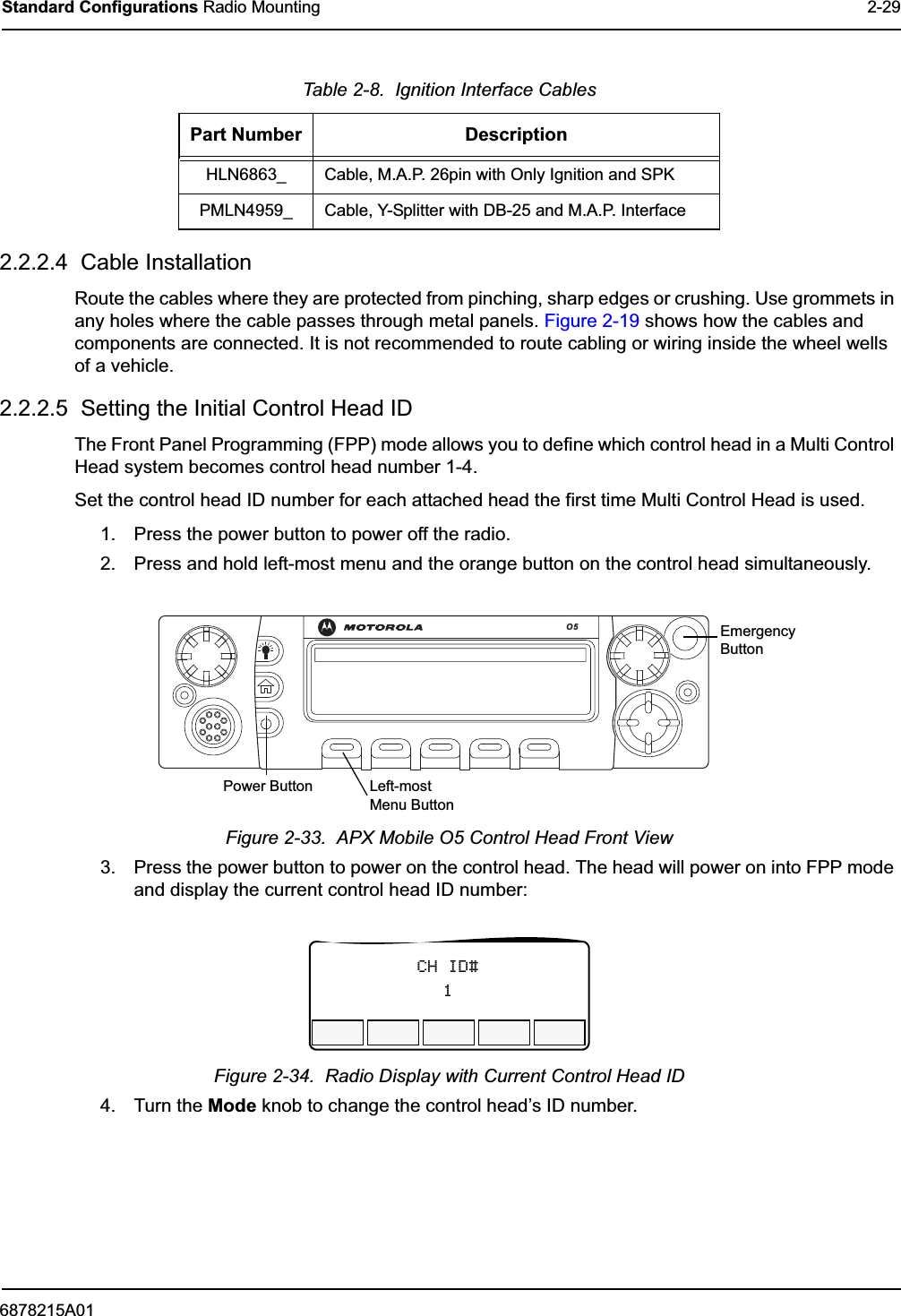
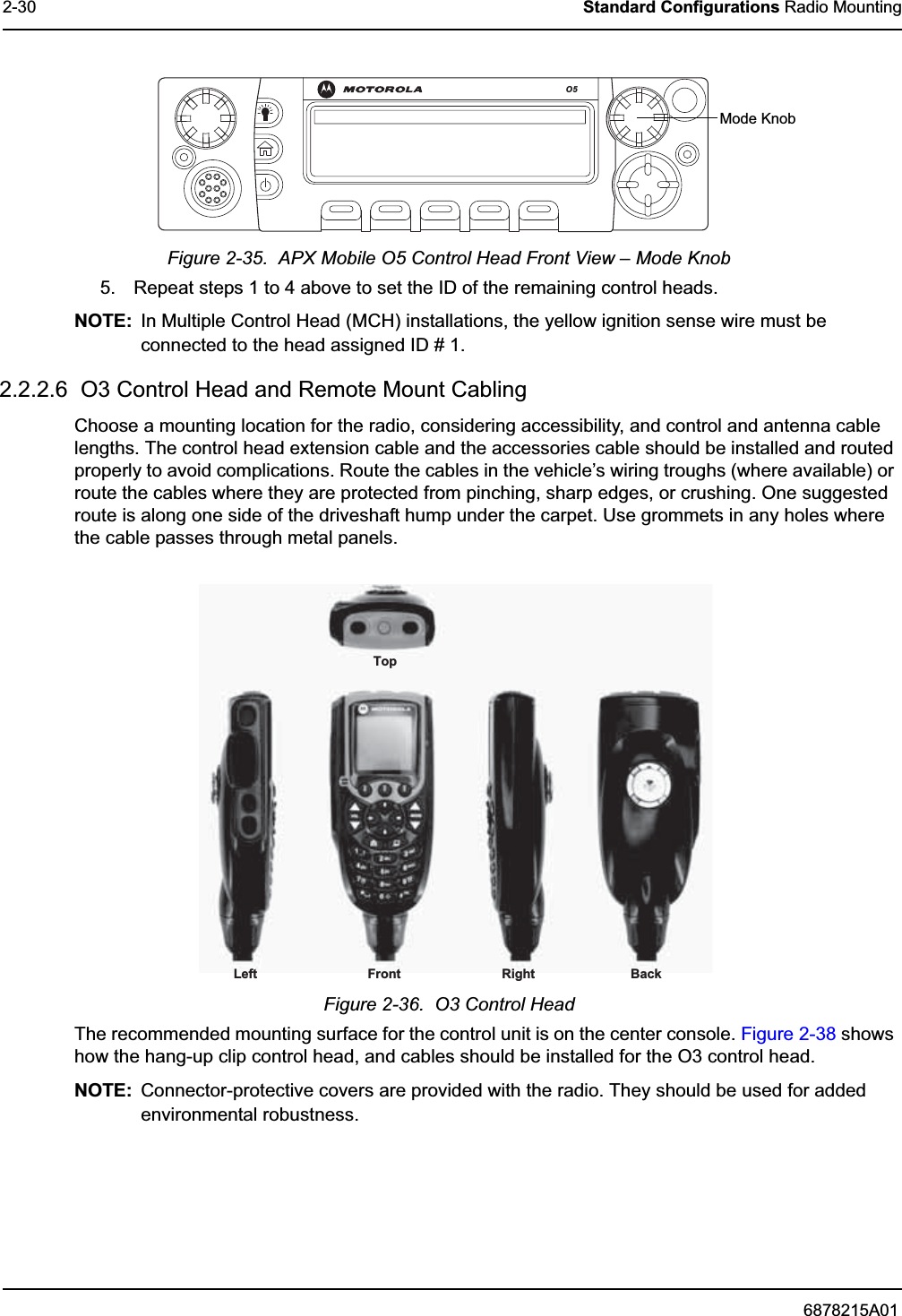
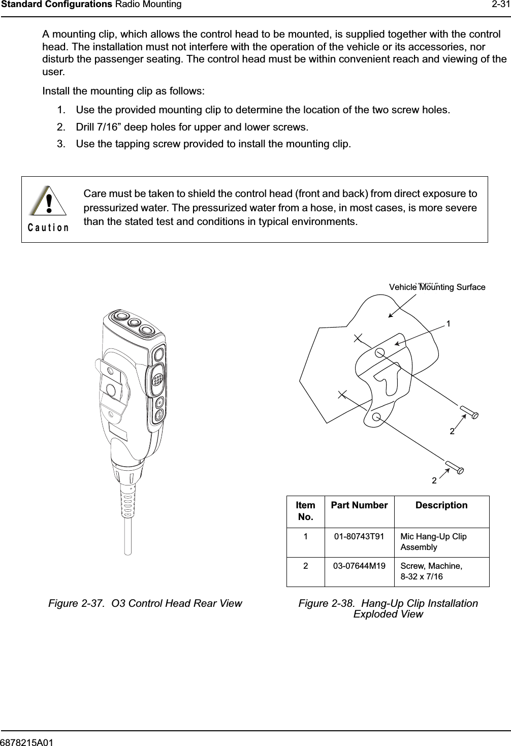
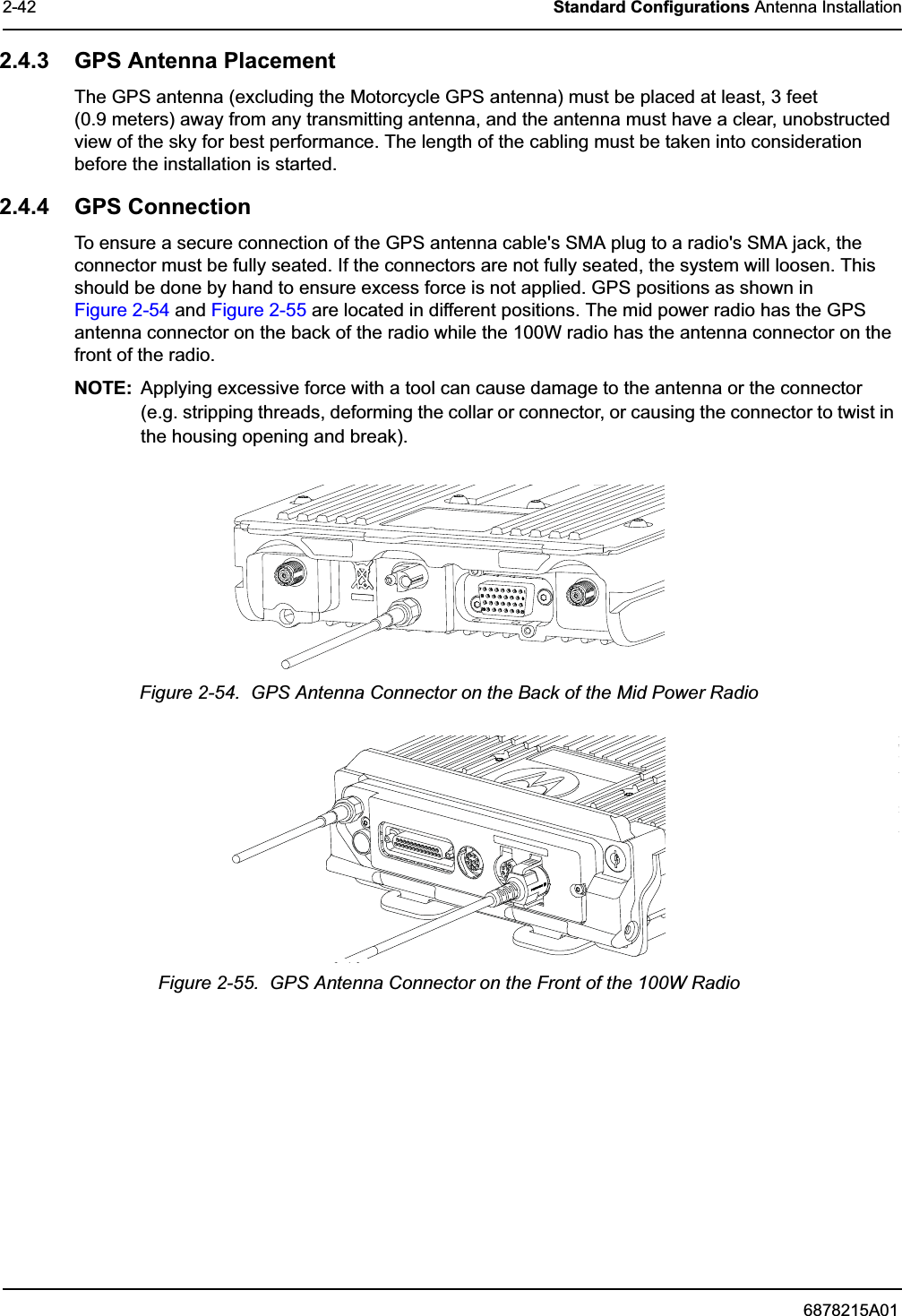
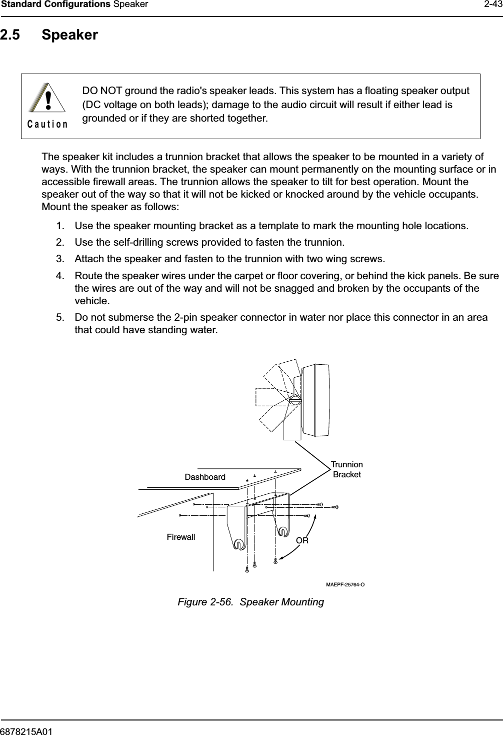
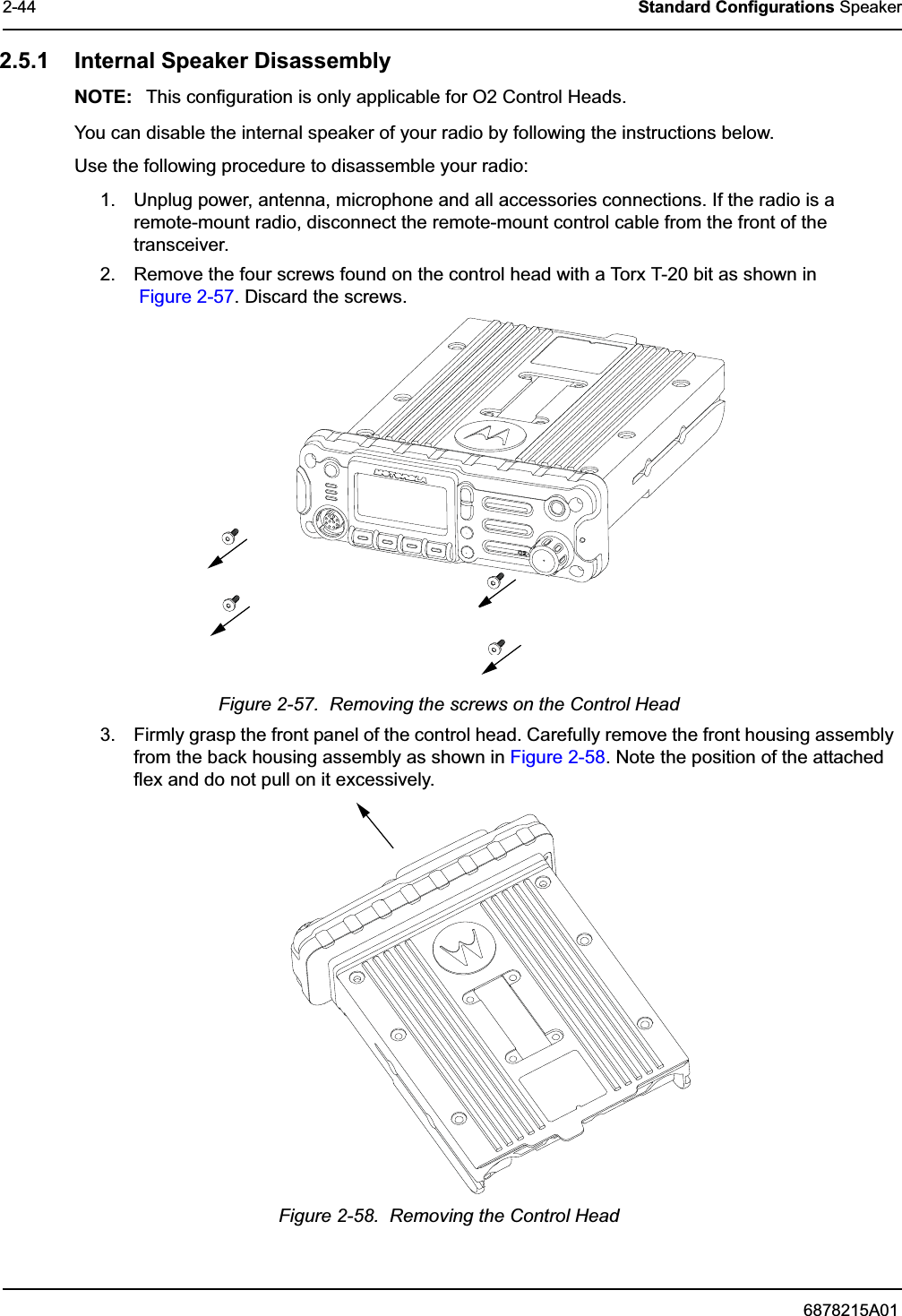
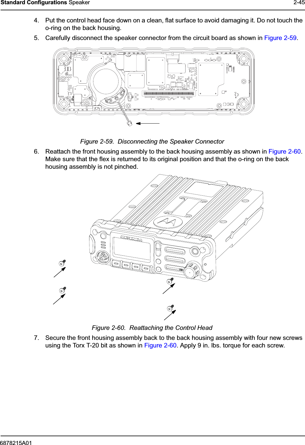
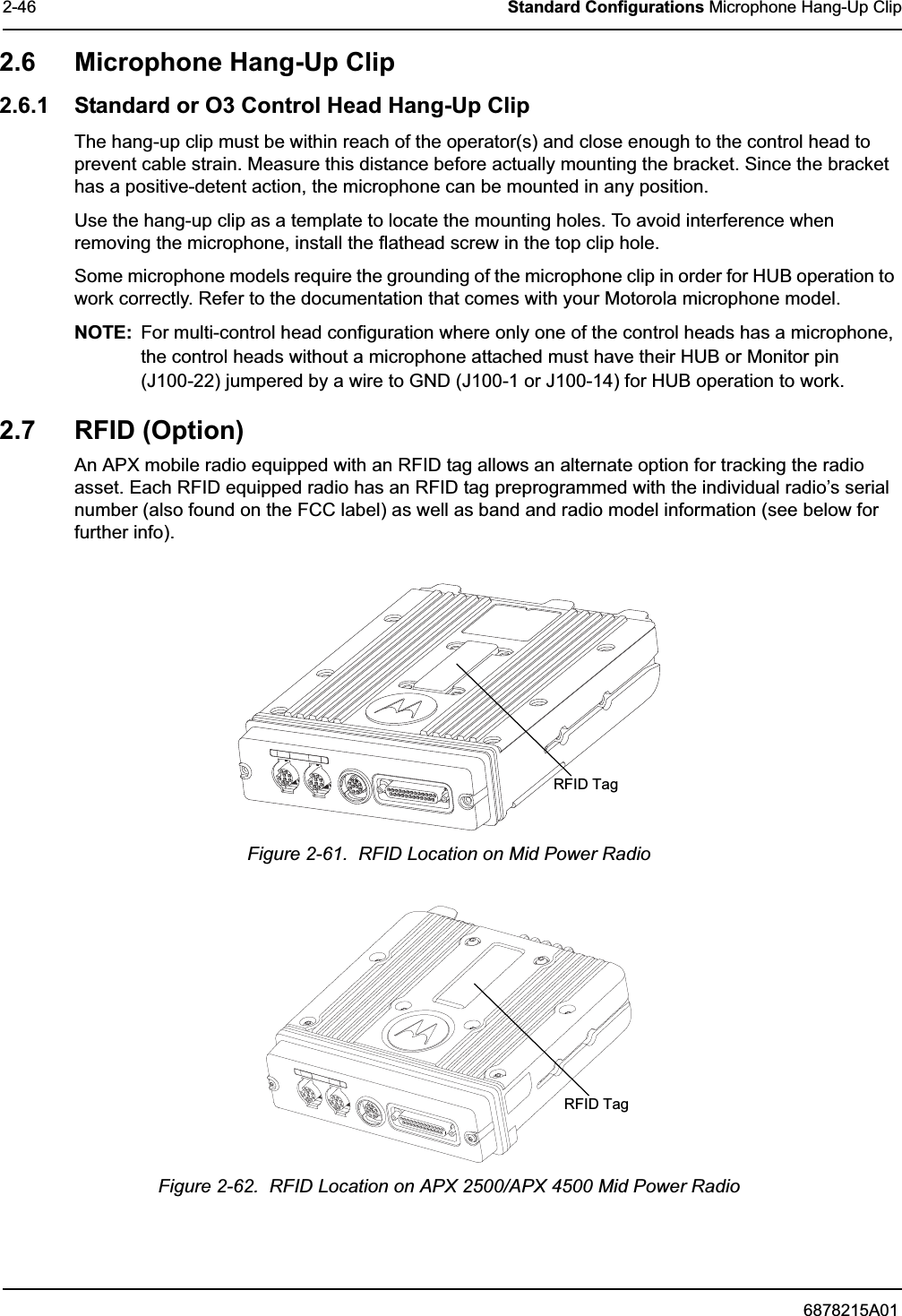
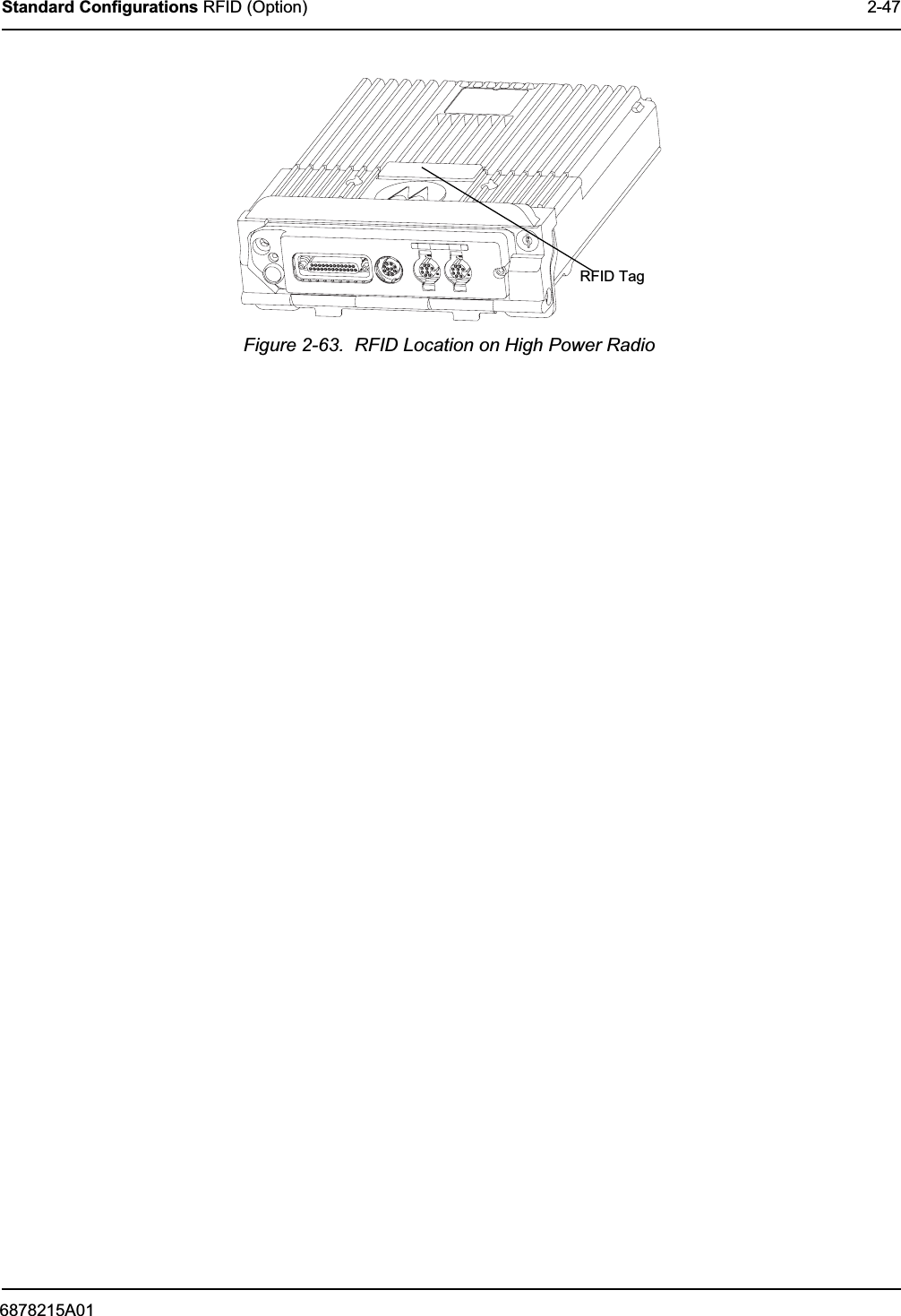
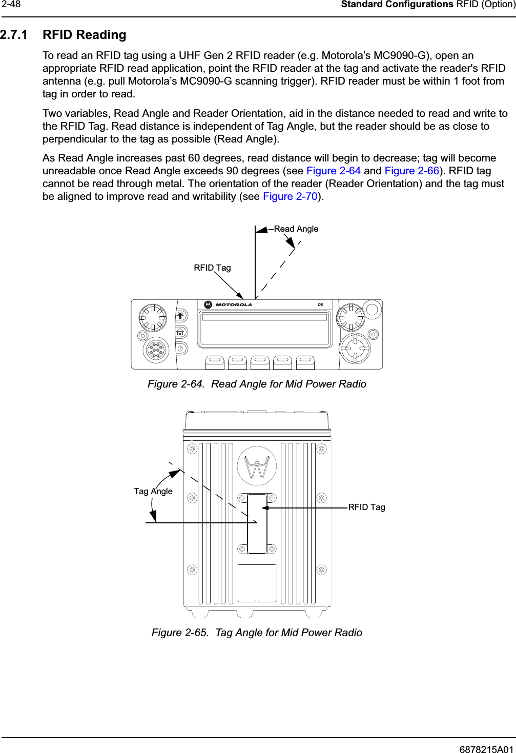
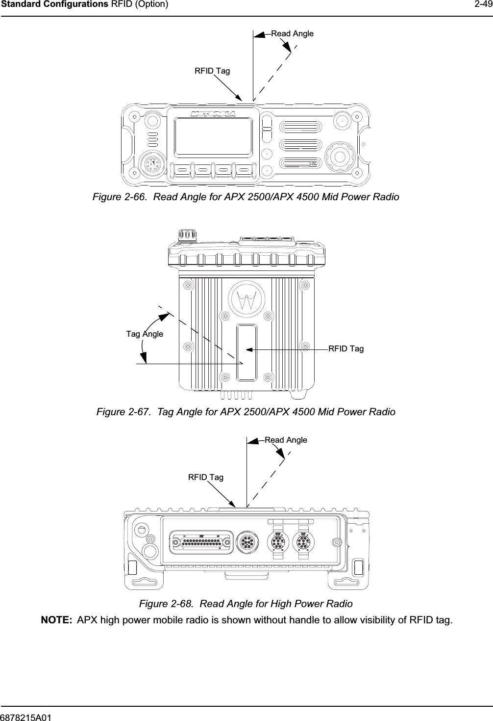
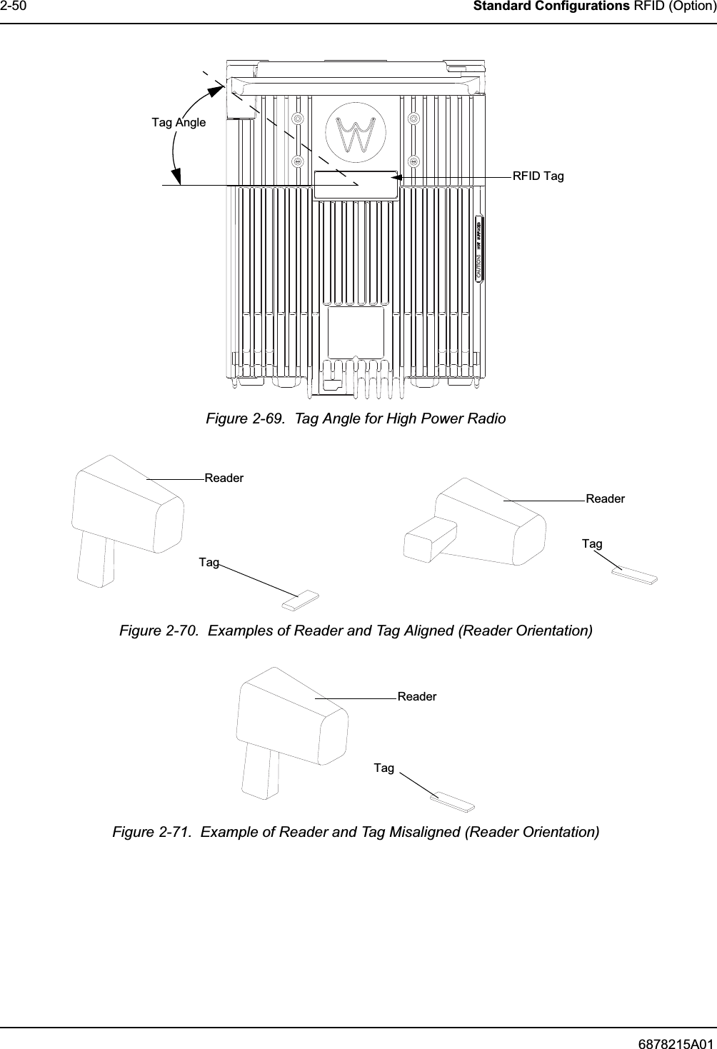
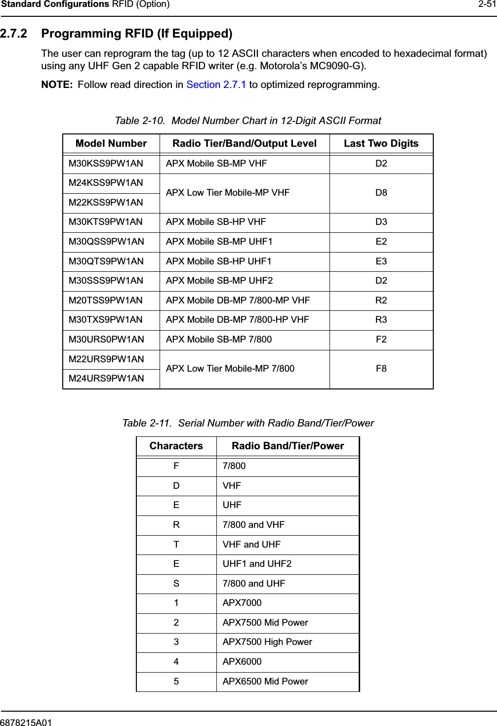
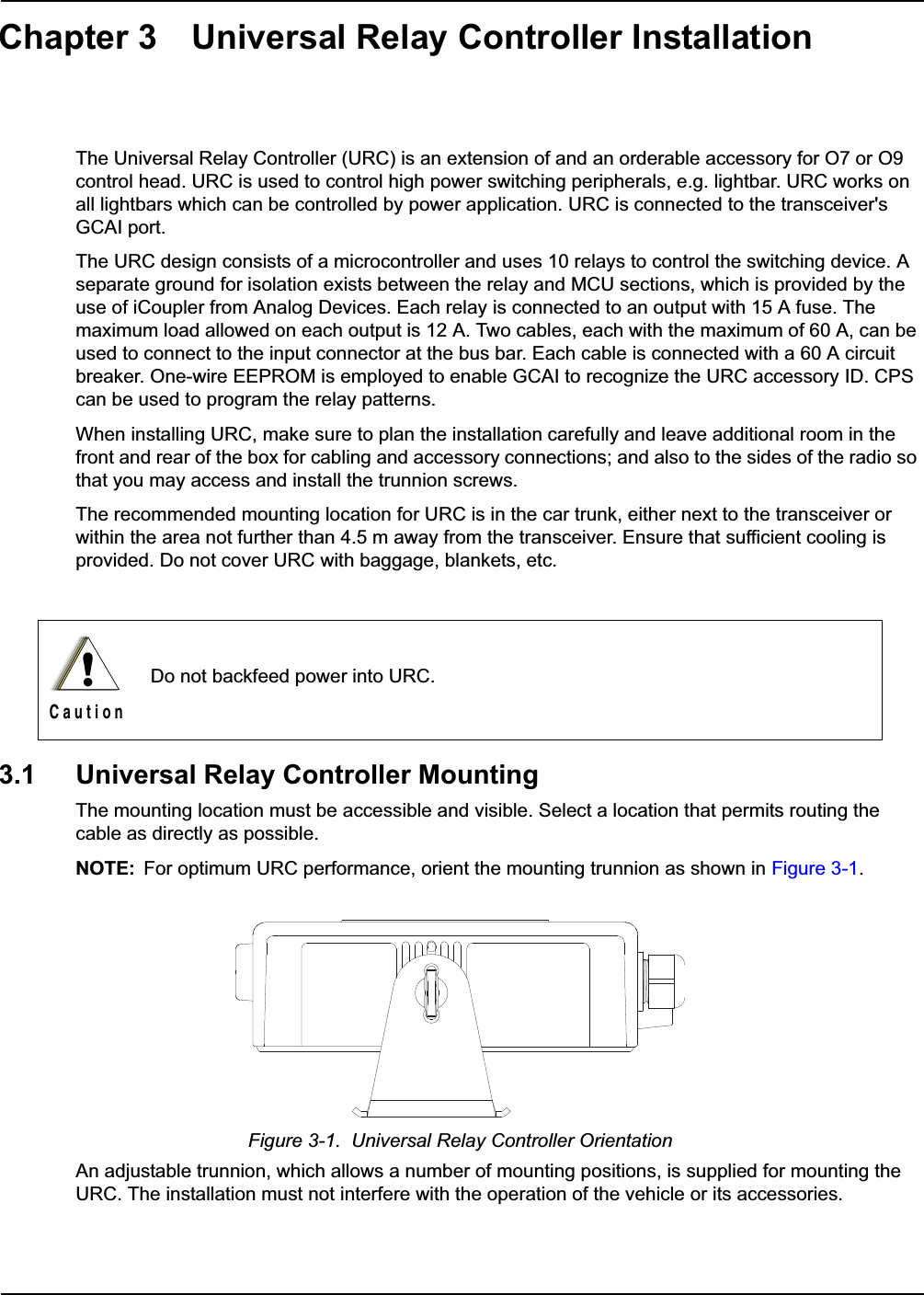
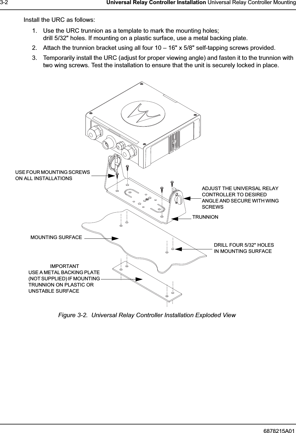
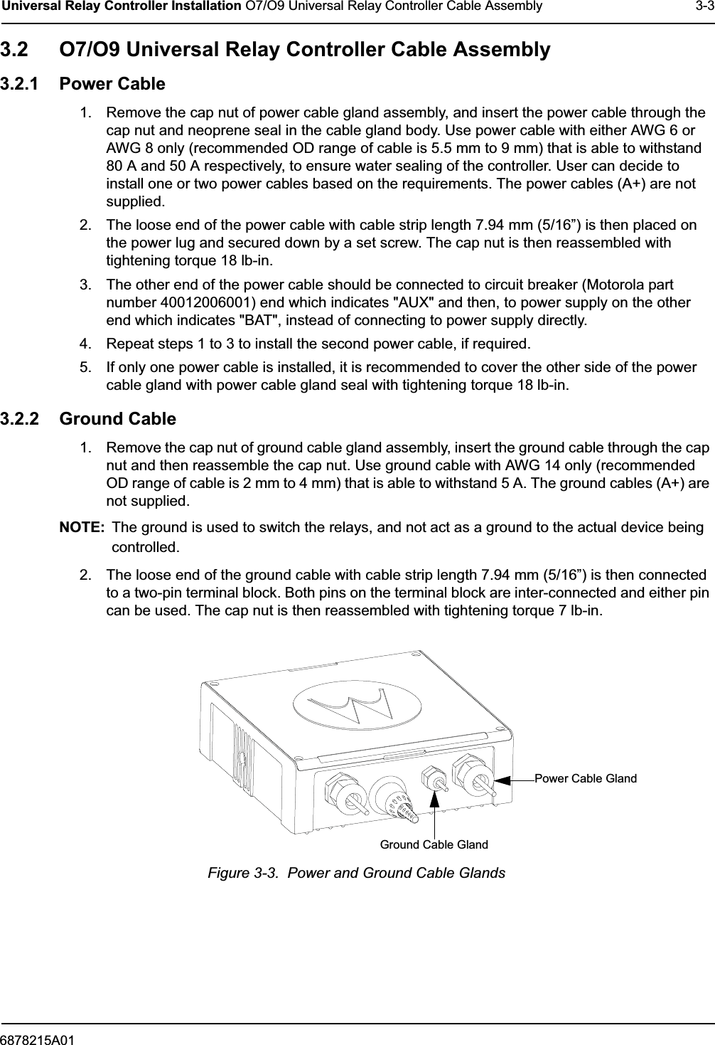
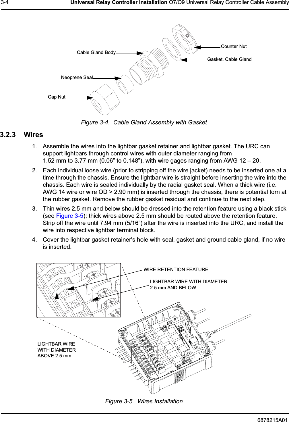
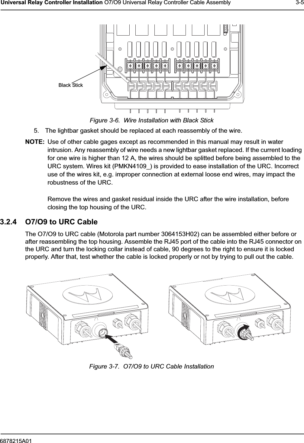
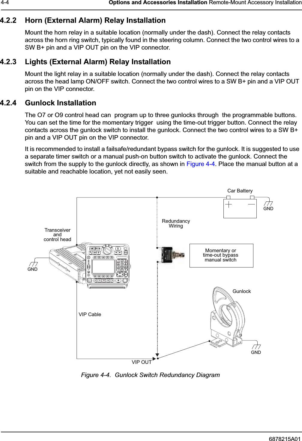
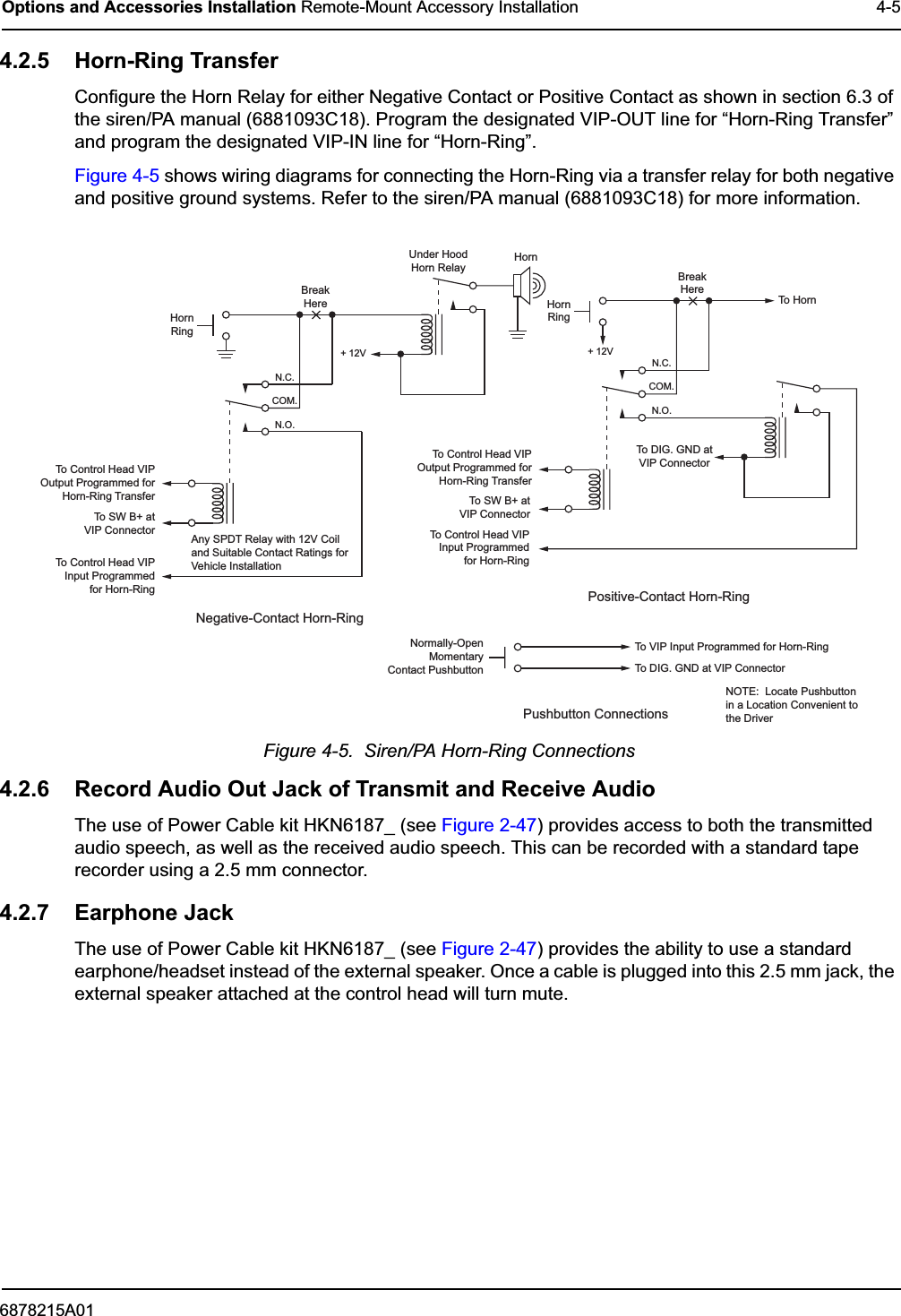
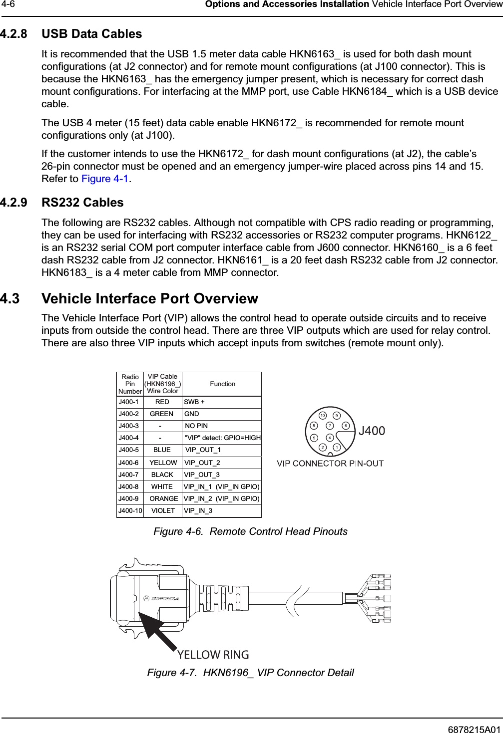
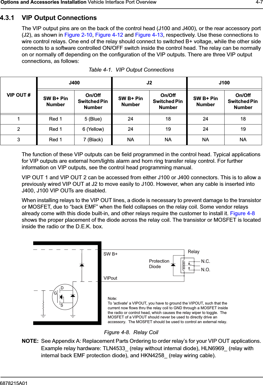
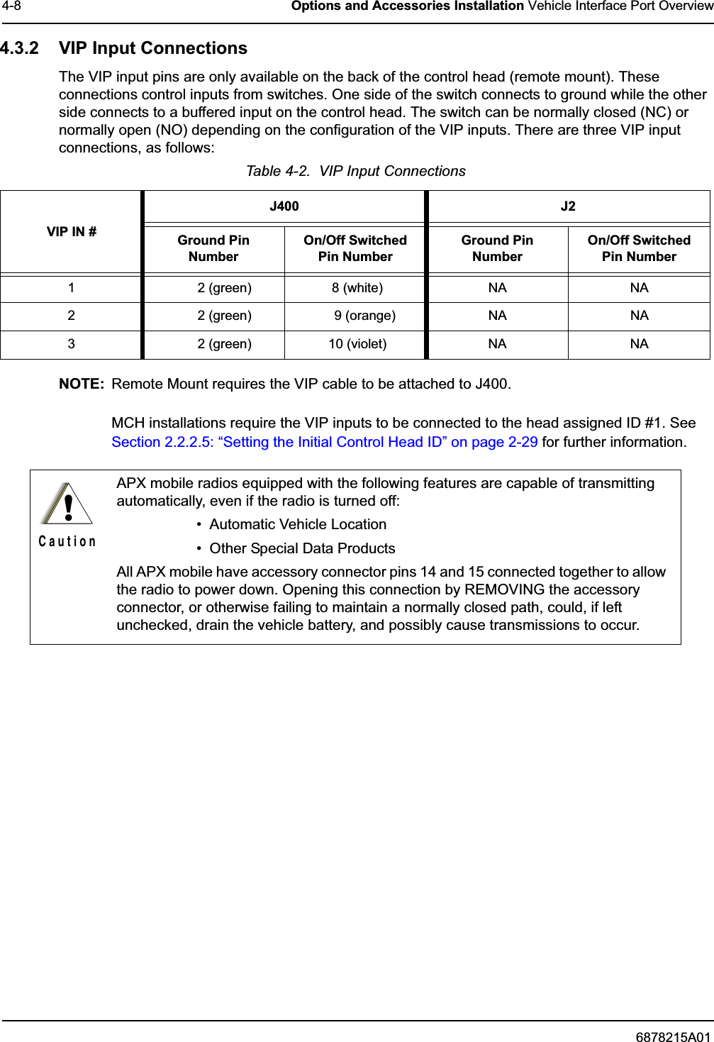
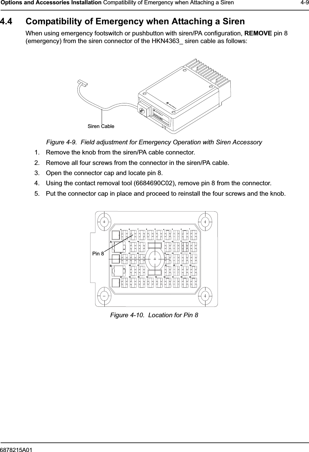
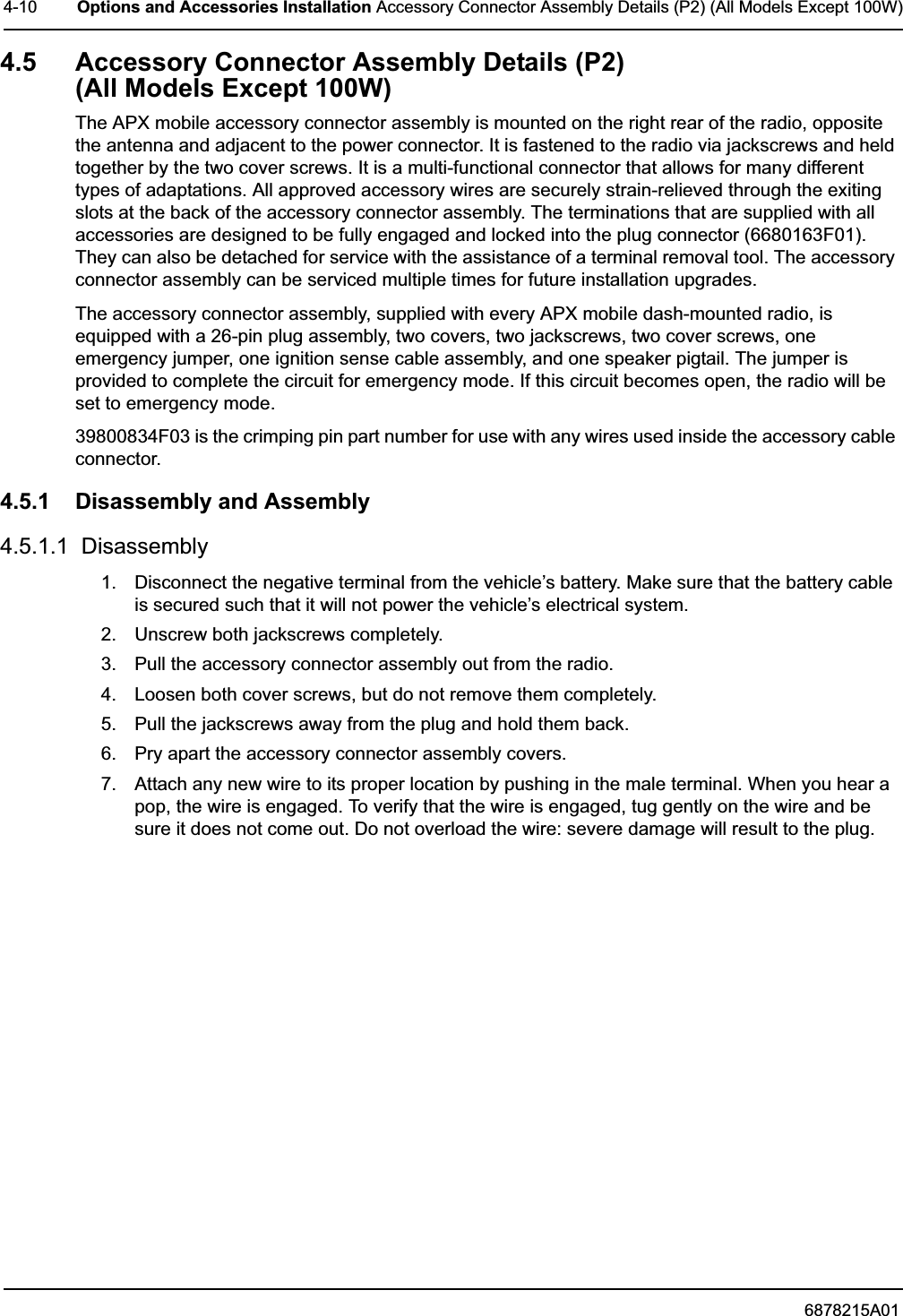
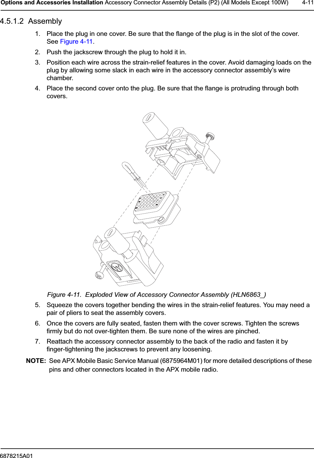
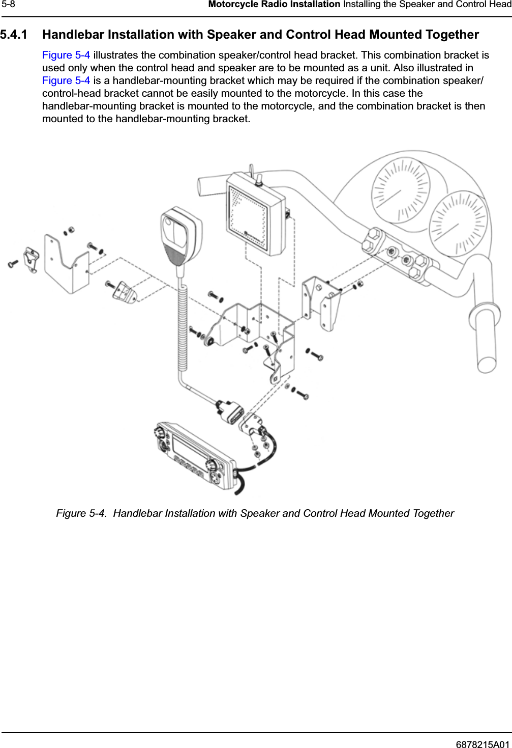
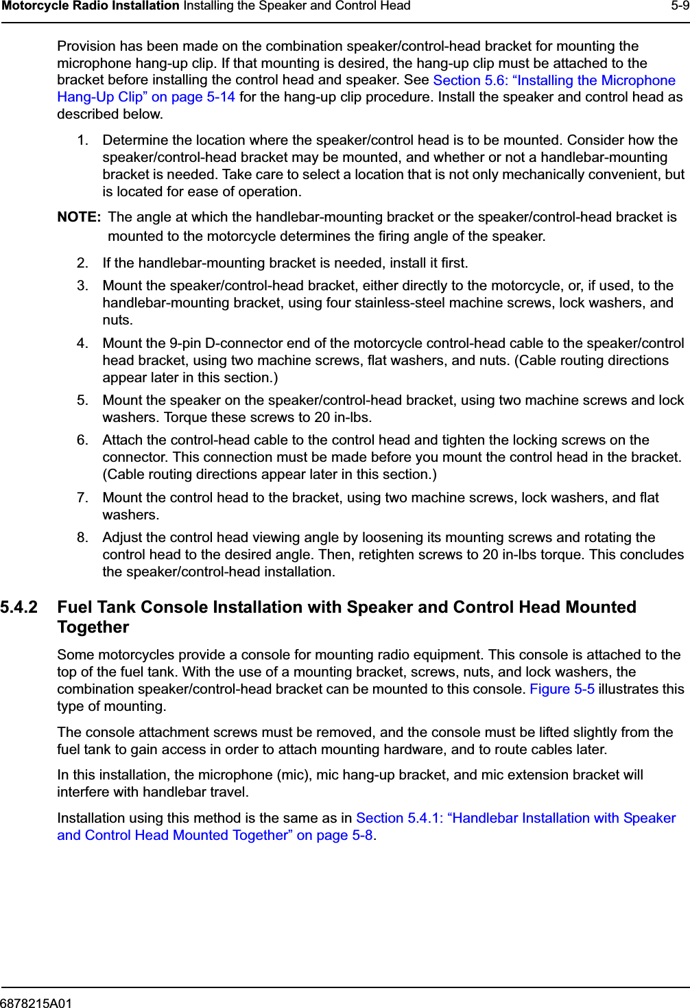
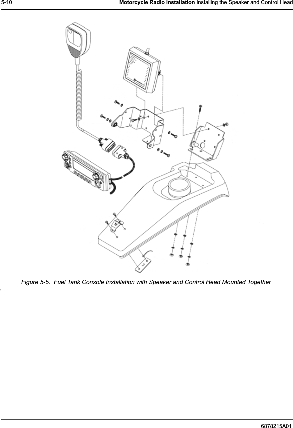
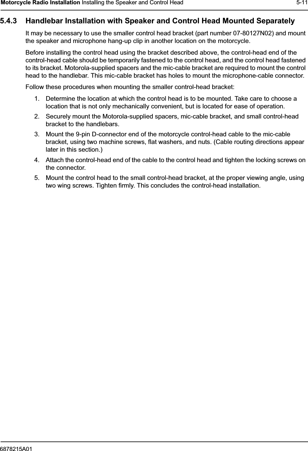
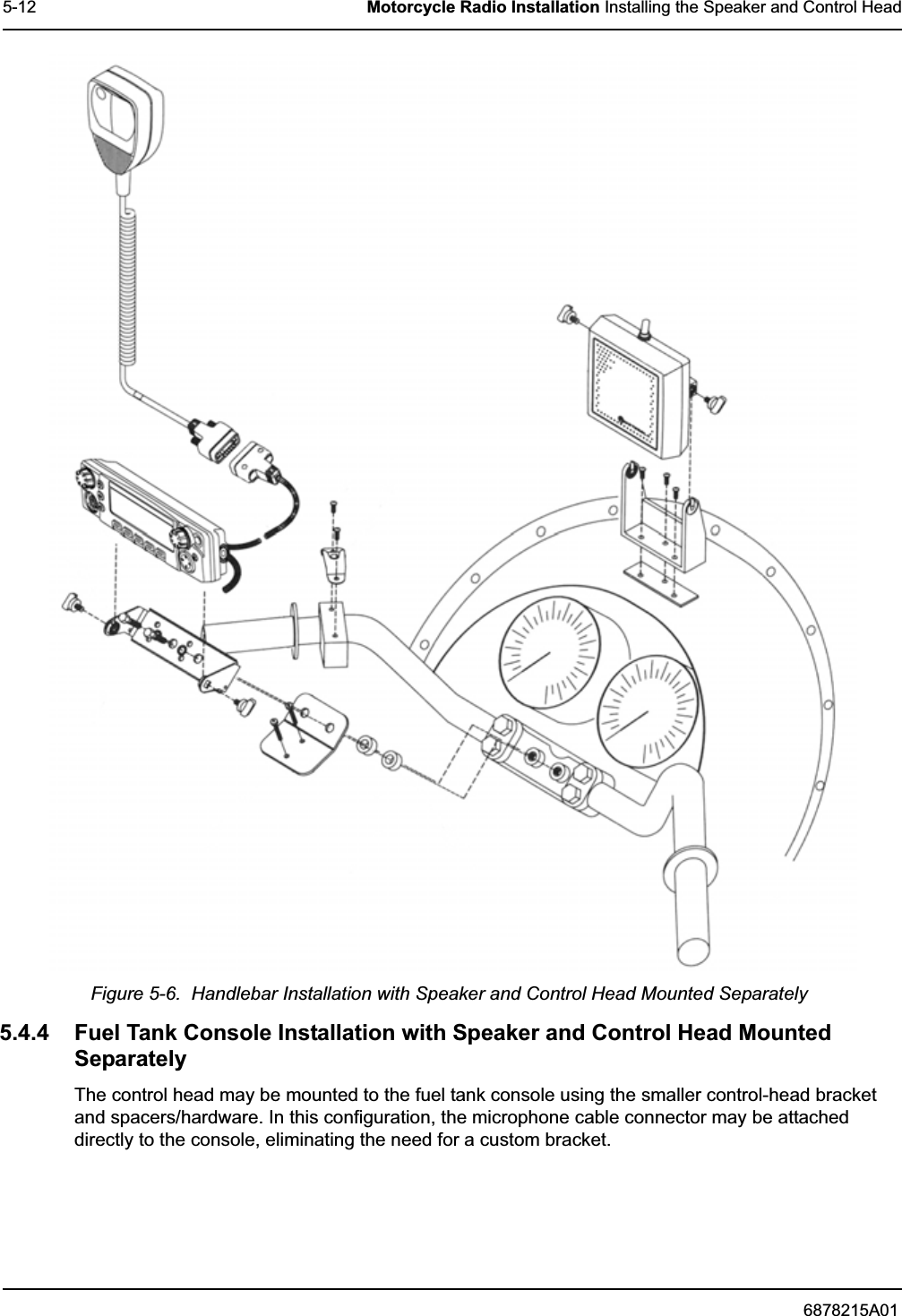
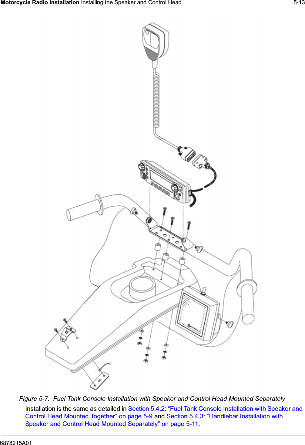
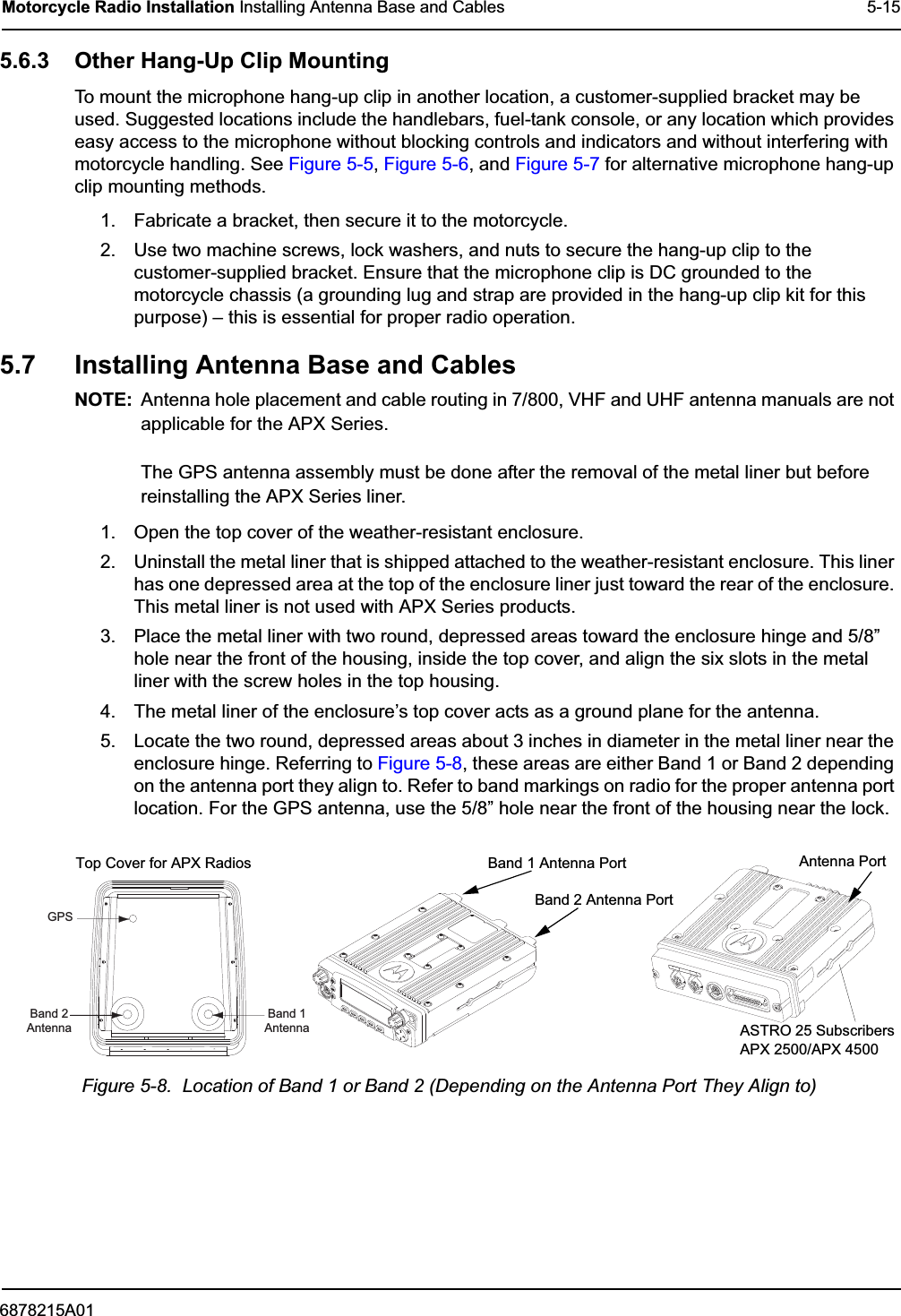
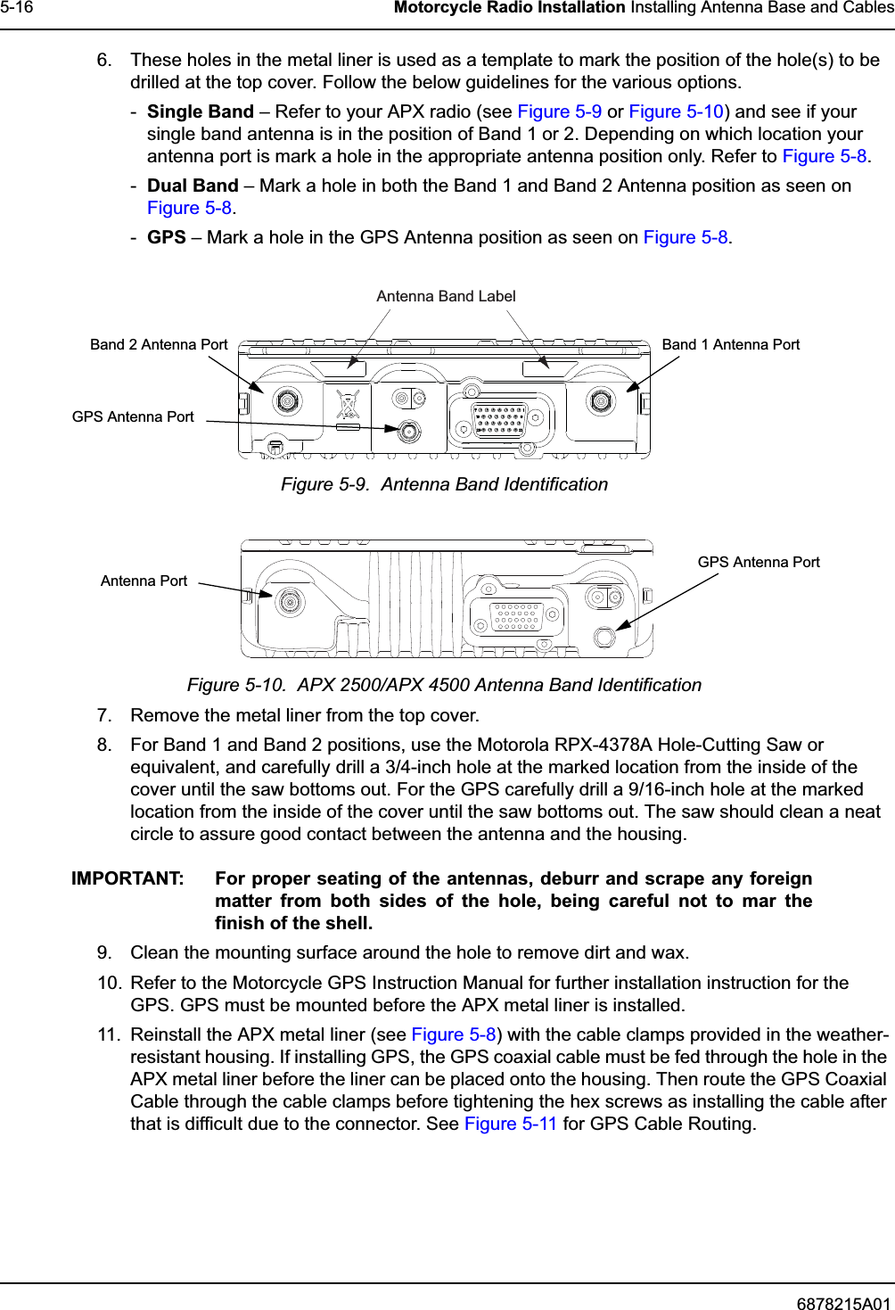
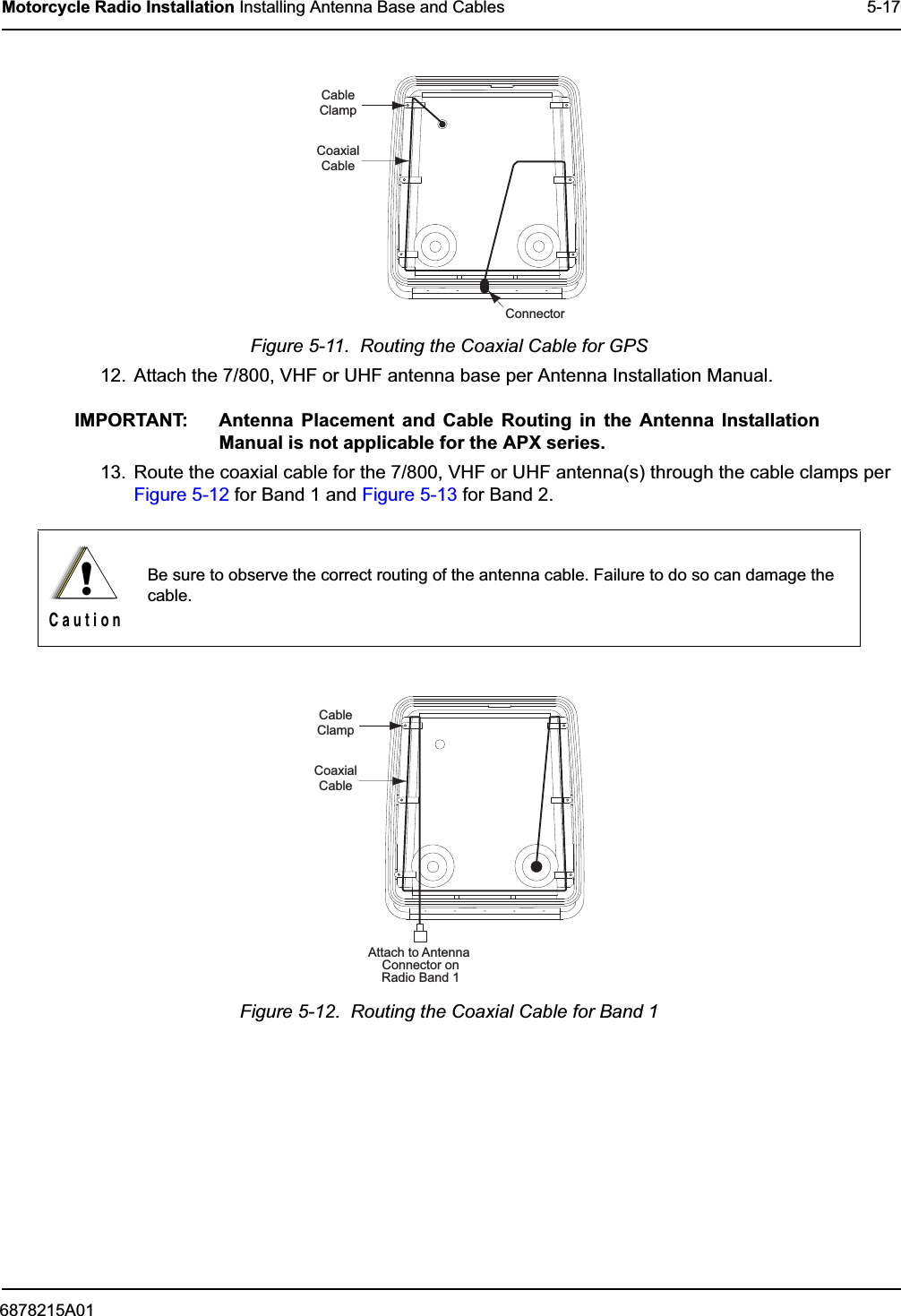
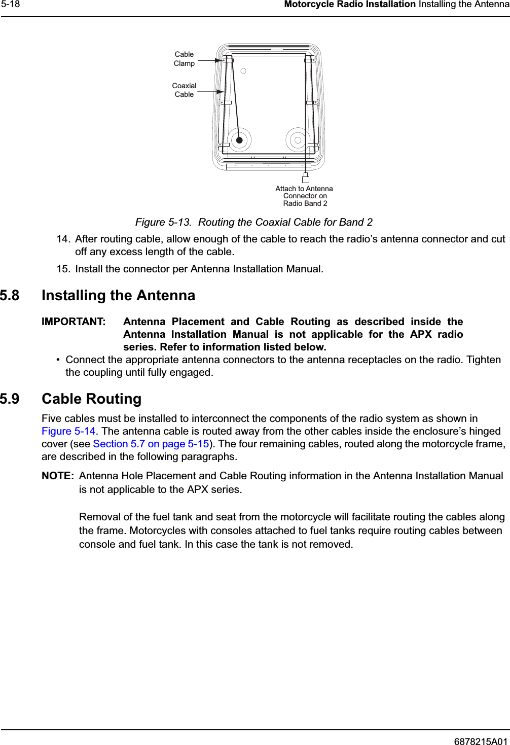
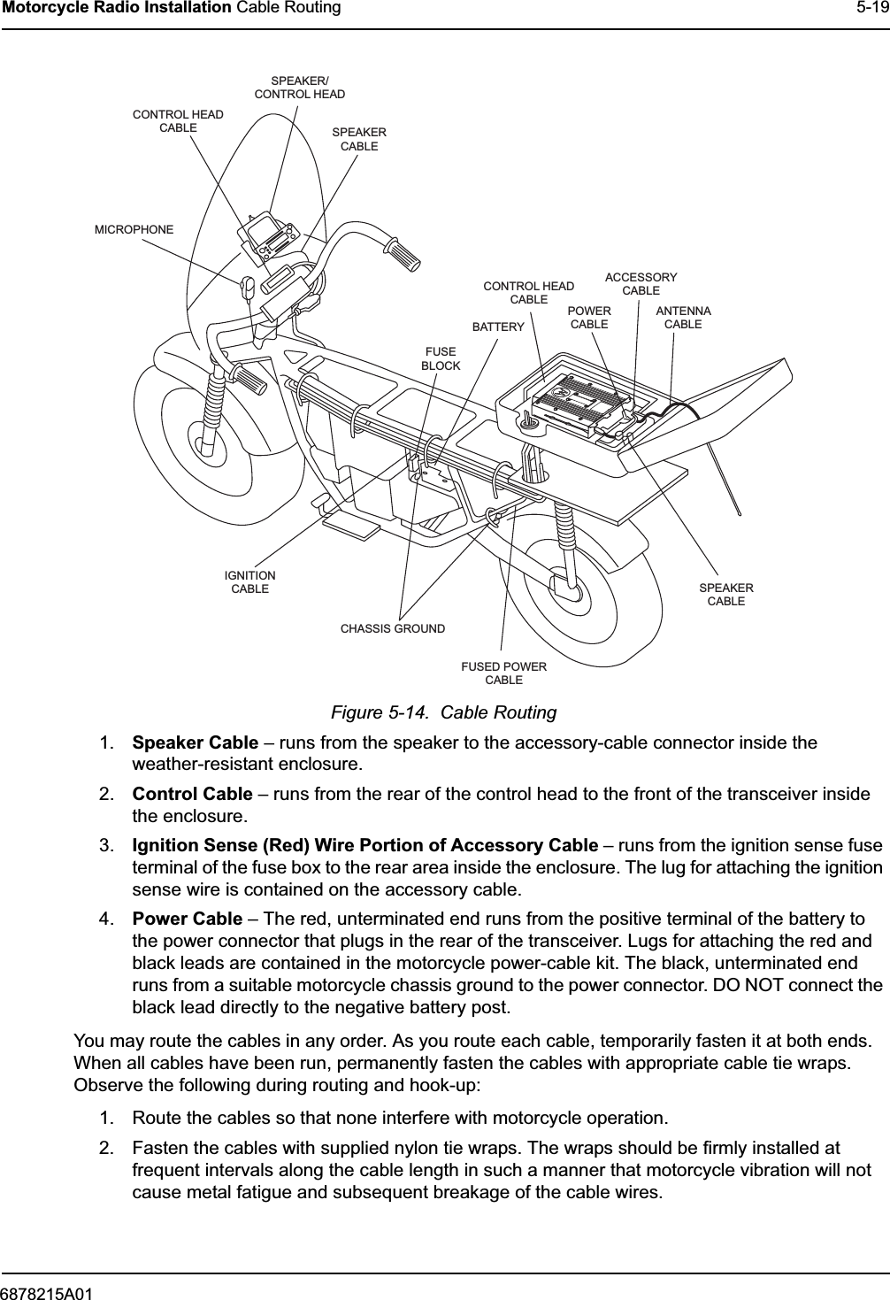
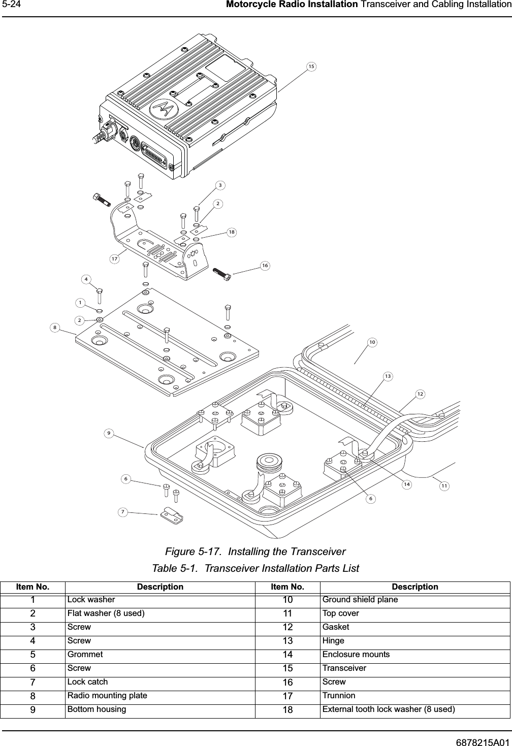
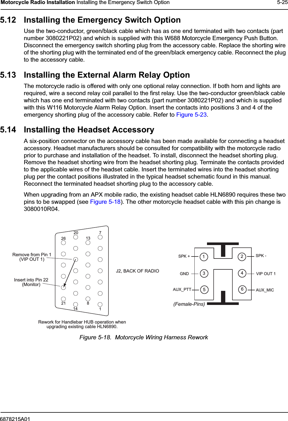
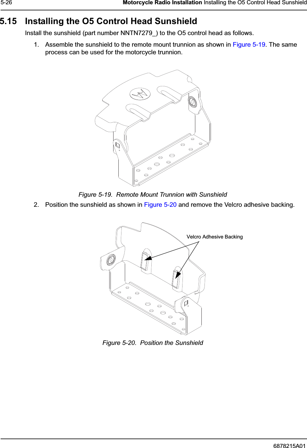
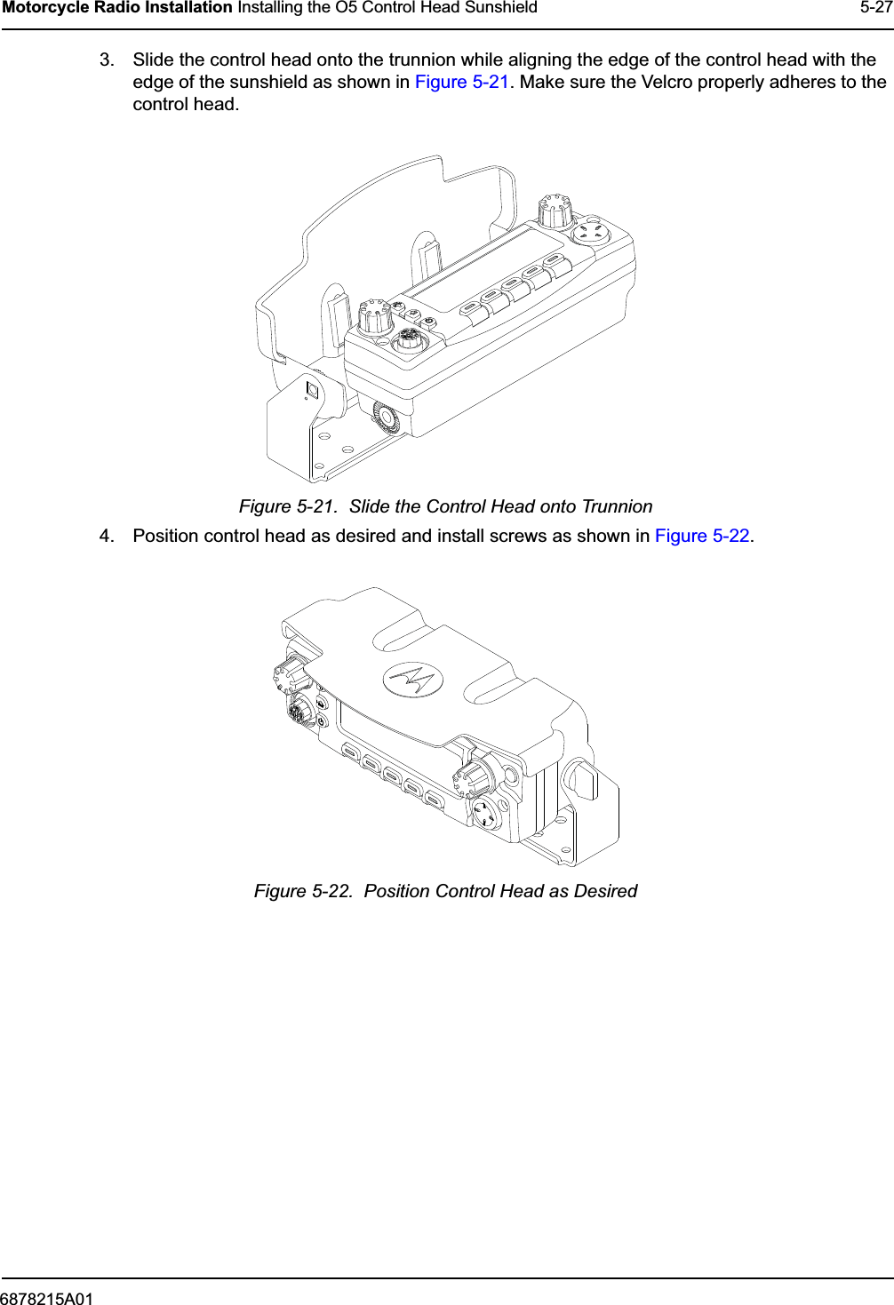
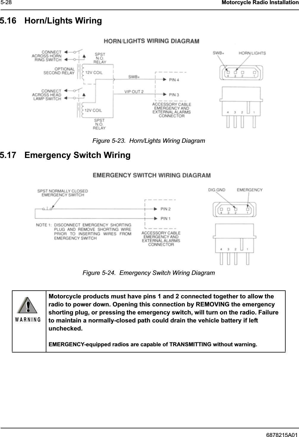
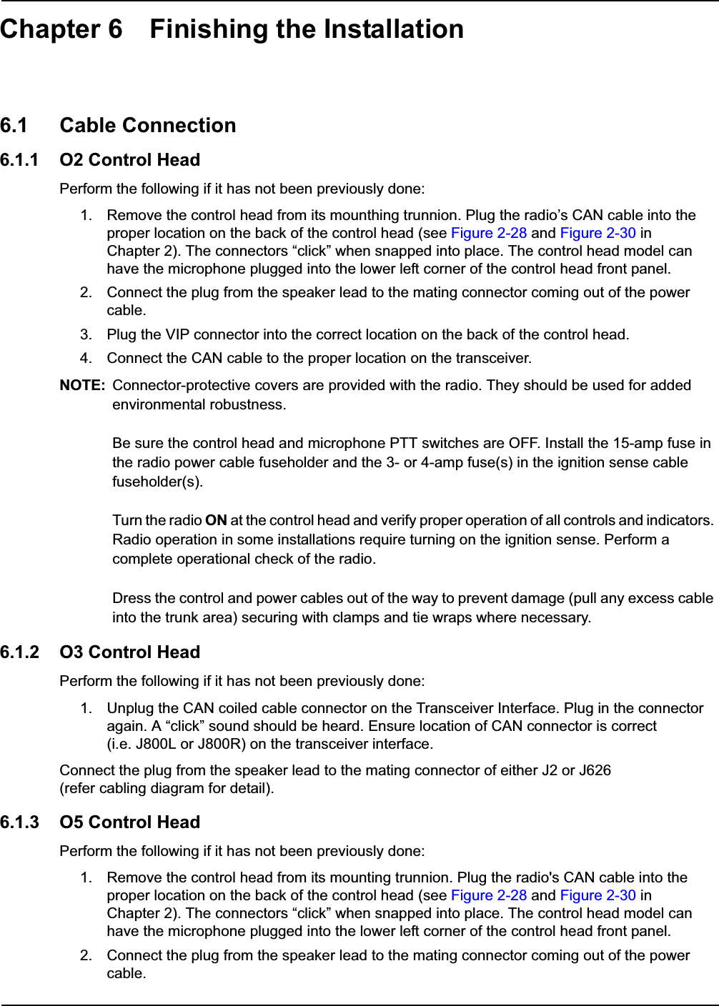
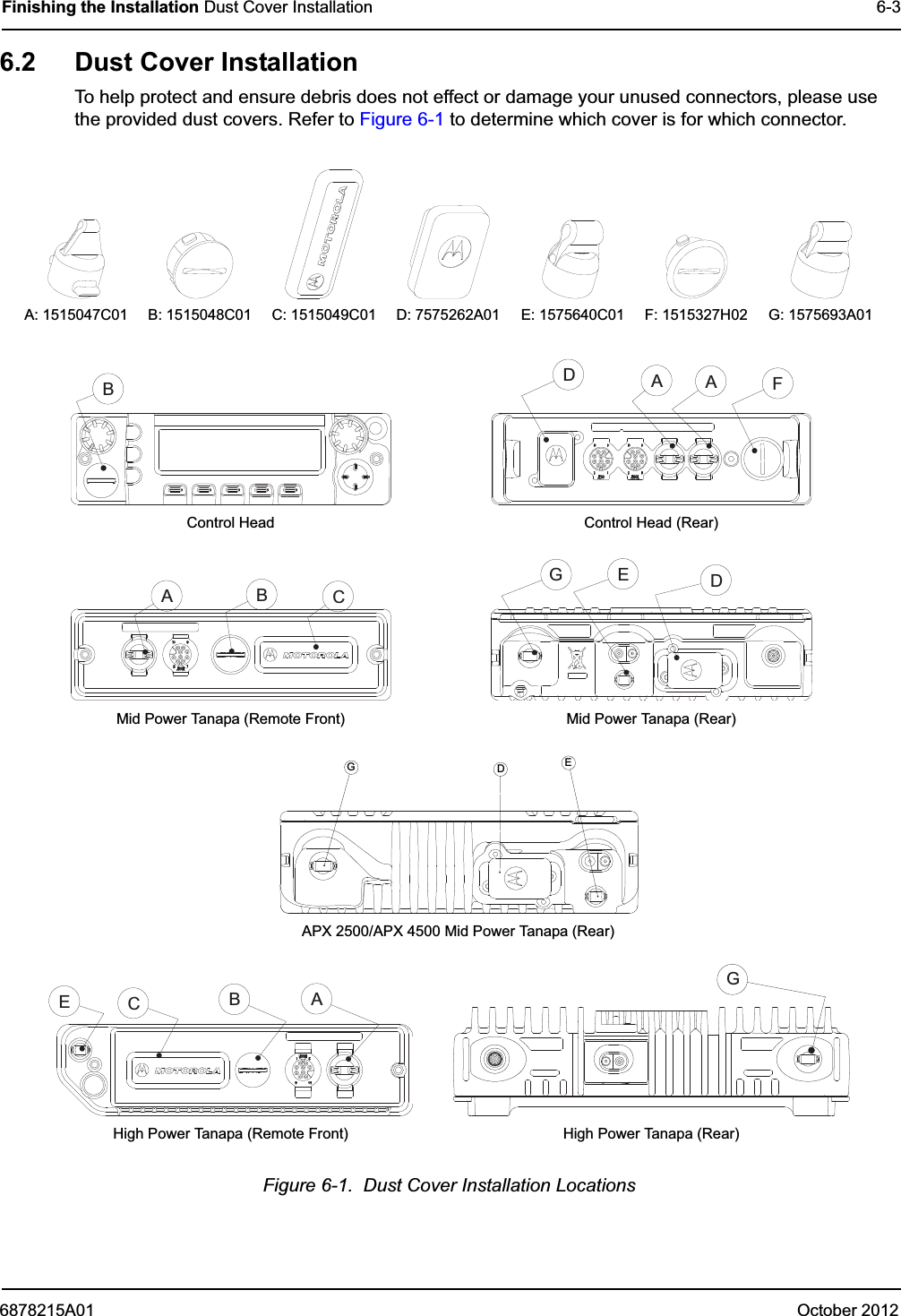
Installation Manual
Installation Manual
Navigation menu
Upload a User Manual
Namespaces
Wiki Guide
HTML
PDF
Info
Views
User Manual
Discussion / Help
Navigation