Motorola Solutions 92FT3826 Mobile 2-Way Radio User Manual Installation Manual
Motorola Solutions, Inc. Mobile 2-Way Radio Installation Manual
Contents
- 1. Ex 8 User Guide
- 2. Installation Manual
Installation Manual
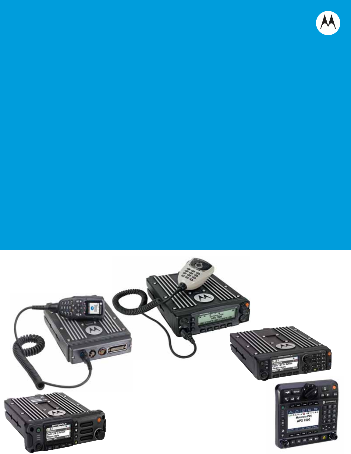
APX™ TWO-WAY RADIOS
APX MOBILES
O2, O3, O5, O7 & O9
CONTROL HEAD
INSTALLATION MANUAL

0

i
Foreword
This manual covers the O2, O3, O5, O7 and O9 models of the ASTRO® APX™ mobile radios. It includes all the information
necessary to install mid power and high power radios, and configure radio installation inside vehicles.
For details on radio operation or component-level troubleshooting, refer to the applicable manuals available separately. A
list of related publications is provided in the section “Related Publications,” on page vi.
RF Energy Exposure and Product Safety Guide for Mobile Two-way Radios
See “Installation Requirements for Compliance with Radio Frequency (RF) Energy Exposure Safety Standards,” on page ii.
Manual Revisions
Changes which occur after this manual is printed are described in PMRs (Publication Manual Revisions). These PMRs
provide complete replacement pages for all added, changed, and deleted items.
To obtain PMRs, go to https://businessonline.motorola.com.
Parts Ordering
See Appendix A: Replacement Parts Ordering for information on how to obtain replacement parts. For part numbers, refer
to the ASTRO APX Mobile Radio Basic Service Manual (Motorola publication part number 6875964M01).
Computer Software Copyrights
The Motorola products described in this manual may include copyrighted Motorola computer programs stored in
semiconductor memories or other media. Laws in the United States and other countries preserve for Motorola certain
exclusive rights for copyrighted computer programs, including, but not limited to, the exclusive right to copy or reproduce in
any form the copyrighted computer program. Accordingly, any copyrighted Motorola computer programs contained in the
Motorola products described in this manual may not be copied, reproduced, modified, reverse-engineered, or distributed in
any manner without the express written permission of Motorola. Furthermore, the purchase of Motorola products shall not
be deemed to grant either directly or by implication, estoppel, or otherwise, any license under the copyrights, patents or
patent applications of Motorola, except for the normal non-exclusive license to use that arises by operation of law in the
sale of a product.
Document Copyrights
No duplication or distribution of this document or any portion thereof shall take place without the express written permission
of Motorola. No part of this manual may be reproduced, distributed, or transmitted in any form or by any means, electronic
or mechanical, for any purpose without the express written permission of Motorola.
Disclaimer
The information in this document is carefully examined, and is believed to be entirely reliable. However, no responsibility is
assumed for inaccuracies. Furthermore, Motorola reserves the right to make changes to any products herein to improve
readability, function, or design. Motorola does not assume any liability arising out of the applications or use of any product
or circuit described herein; nor does it cover any license under its patent rights nor the rights of others.
Trademarks
MOTOROLA, MOTO, MOTOROLA SOLUTIONS and the Stylized M logo are trademarks or registered trademarks of
Motorola Trademark Holdings, LLC and are used under license. All other trademarks are the property of their respective
owners.
© 2009 – 2012 by Motorola Solutions, Inc.
All rights reserved.

ii
Installation Requirements for Compliance with
Radio Frequency (RF) Energy Exposure Safety
Standards
ATTENTION!
This radio is intended for use in occupational/controlled conditions, where users have full knowledge
of their exposure and can exercise control over their exposure to meet FCC limits. This radio device is
NOT authorized for general population, consumer, or any other use.
To ensure compliance to RF Energy Safety Standards:
• Install only Motorola approved antennas and accessories
• Be sure that antenna installation is per “Antenna Installation,” on page 2-38 of this manual
• Be sure that Product Safety and RF Safety Booklet enclosed with this radio is available to the end user
upon completion of the installation of this radio
Before using this product, read the guide enclosed with your radio which contains important operating
instructions for safe usage and RF energy awareness and control for compliance with applicable standards
and regulations.
For a list of Motorola-approved antennas and other accessories, visit the following web site which lists
approved accessories for your radio model: http://www.motorolasolutions.com.

Table of Contents iii
6878215A01
Table of Contents
Foreword..........................................................................................................i
RF Energy Exposure and Product Safety Guide for Mobile Two-way Radios..............................................i
Manual Revisions .........................................................................................................................................i
Parts Ordering ..............................................................................................................................................i
Computer Software Copyrights ....................................................................................................................i
Document Copyrights ...................................................................................................................................i
Disclaimer.....................................................................................................................................................i
Trademarks ..................................................................................................................................................i
Installation Requirements for Compliance with
Radio Frequency (RF) Energy Exposure Safety Standards.......................ii
Mobile Radio Model Numbering Scheme..................................................xiii
Commercial Warranty ..................................................................................xv
Limited Warranty .......................................................................................................................................xv
MOTOROLA COMMUNICATION PRODUCTS...............................................................................xv
I. What This Warranty Covers And For How Long ....................................................................xv
II. General Provisions ................................................................................................................xv
III. State Law Rights ................................................................................................................. xvi
IV. How To Get Warranty Service ............................................................................................ xvi
V. What This Warranty Does Not Cover................................................................................... xvi
VI. Patent And Software Provisions ........................................................................................ xvii
VII. Governing Law.................................................................................................................. xvii
Chapter 1 Introduction ......................................................................... 1-1
1.1 Mobile Radio Description............................................................................................................... 1-1
1.1.1 Dimensions ....................................................................................................................... 1-1
1.2 Standard Configurations ................................................................................................................ 1-5
1.2.1 Dash Mount Configuration ................................................................................................ 1-5
1.2.2 Remote Mount Configuration............................................................................................ 1-7
1.2.3 Multi Control Head .......................................................................................................... 1-13
1.3 Motorcycle Configurations ........................................................................................................... 1-14
1.4 Base/Control Stations .................................................................................................................. 1-14
1.5 Tools Required for APX Mobile Installations ............................................................................... 1-14
Chapter 2 Standard Configurations .................................................... 2-1
2.1 Planning the Installation................................................................................................................. 2-1
2.1.3 Radio Operation Wiring for Dash and Remote Configurations ....................................... 2-14
2.1.3.1 Dash Mount: Power, Ignition, and Emergency Cable Installation.......................... 2-14
2.1.3.2 Remote Mount: Power, Ignition, and Emergency Cable Installation...................... 2-15
2.1.4 Ignition Sense Switch (Radio Wide Advance) ................................................................ 2-17
2.1.5 Siren/PA Configuration/Programming............................................................................. 2-18

iv Table of Contents
6878215A01
2.2 Radio Mounting ........................................................................................................................... 2-19
2.2.2 Remote Mount with Trunnion.......................................................................................... 2-23
2.2.2.1 100W Radios Only................................................................................................. 2-24
2.2.2.2 Remote Mount Control Head Installation............................................................... 2-24
2.2.2.3 Multiple Control Head Installation.......................................................................... 2-27
2.2.2.4 Cable Installation ................................................................................................... 2-29
2.2.2.5 Setting the Initial Control Head ID ......................................................................... 2-29
2.2.2.6 O3 Control Head and Remote Mount Cabling ....................................................... 2-30
2.2.3 Locking Kit (Optional) .....................................................................................................2-32
2.2.3.1 All Radios Except 100W ........................................................................................ 2-32
2.2.3.2 100W Radios ......................................................................................................... 2-32
2.3 Power Cables (Transceiver and Control Head) ........................................................................... 2-33
2.3.1 Optional Locking Feature for High Power Chassis Power Cables.................................. 2-33
2.3.2 O2, O5, O7 or O9 Control Head Power Cables.............................................................. 2-36
2.3.3 Battery Selector Switch................................................................................................... 2-37
2.4 Antenna Installation ..................................................................................................................... 2-38
2.4.1 Selecting an Antenna Site/Location on a Metal Body Vehicle ........................................ 2-38
2.4.2 Mini-UHF Connection ..................................................................................................... 2-40
2.4.3 GPS Antenna Placement................................................................................................ 2-42
2.4.4 GPS Connection .............................................................................................................2-42
2.5 Speaker ....................................................................................................................................... 2-43
2.5.1 Internal Speaker Disassembly ........................................................................................ 2-44
2.6 Microphone Hang-Up Clip ........................................................................................................... 2-46
2.6.1 Standard or O3 Control Head Hang-Up Clip .................................................................. 2-46
2.7 RFID (Option) .............................................................................................................................. 2-46
2.7.1 RFID Reading ................................................................................................................. 2-48
2.7.2 Programming RFID (If Equipped) ................................................................................... 2-51
2.8 Completing the Installation .......................................................................................................... 2-52
Chapter 3 Universal Relay Controller Installation ............................. 3-1
3.1 Universal Relay Controller Mounting ............................................................................................. 3-1
3.2 O7/O9 Universal Relay Controller Cable Assembly ...................................................................... 3-3
3.2.1 Power Cable ..................................................................................................................... 3-3
3.2.2 Ground Cable ................................................................................................................... 3-3
3.2.3 Wires ................................................................................................................................ 3-4
3.2.4 O7/O9 to URC Cable........................................................................................................ 3-5
Chapter 4 Options and Accessories Installation ............................... 4-1
4.1 Dash-Mount Accessory Installation ............................................................................................... 4-1
4.1.1 Dash-Mount Emergency Pushbutton or Footswitch Installation ....................................... 4-1
4.1.2 Dash-Mount Horn and Lights (External Alarms) Relays ................................................... 4-2
4.2 Remote-Mount Accessory Installation ........................................................................................... 4-2
4.2.1 Emergency Pushbutton or Footswitch Installation............................................................ 4-3
4.2.2 Horn (External Alarm) Relay Installation........................................................................... 4-4
4.2.3 Lights (External Alarm) Relay Installation......................................................................... 4-4
4.2.4 Gunlock Installation .......................................................................................................... 4-4
4.2.5 Horn-Ring Transfer ........................................................................................................... 4-5
4.2.6 Record Audio Out Jack of Transmit and Receive Audio................................................... 4-5
4.2.7 Earphone Jack.................................................................................................................. 4-5
4.2.8 USB Data Cables.............................................................................................................. 4-6
4.2.9 RS232 Cables .................................................................................................................. 4-6

Table of Contents v
6878215A01
4.3 Vehicle Interface Port Overview .................................................................................................... 4-6
4.3.1 VIP Output Connections ................................................................................................... 4-7
4.3.2 VIP Input Connections ......................................................................................................4-8
4.4 Compatibility of Emergency when Attaching a Siren ..................................................................... 4-9
4.5 Accessory Connector Assembly Details (P2) (All Models Except 100W).................................... 4-10
4.5.1 Disassembly and Assembly............................................................................................ 4-10
4.5.1.1 Disassembly .......................................................................................................... 4-10
4.5.1.2 Assembly ............................................................................................................... 4-11
4.5.2 Adapter Cable................................................................................................................. 4-12
4.6 Memory and Three-Day Secure Key Retention Option ............................................................... 4-12
Chapter 5 Motorcycle Radio Installation ............................................ 5-1
5.1 Motorcycle Radio Description ........................................................................................................ 5-1
5.1.1 Transceiver Enclosure ......................................................................................................5-1
5.1.2 Control/Display Unit .......................................................................................................... 5-1
5.1.3 Control Head Cable .......................................................................................................... 5-2
5.1.4 Microphone ....................................................................................................................... 5-2
5.1.5 Keypad Mic ....................................................................................................................... 5-2
5.1.6 External Speaker .............................................................................................................. 5-2
5.1.7 Headset Capability............................................................................................................ 5-2
5.1.8 Antenna ............................................................................................................................ 5-2
5.1.9 Ignition Sense (ACC) Wire................................................................................................ 5-2
5.2 Installation Overview...................................................................................................................... 5-3
5.2.1 General ............................................................................................................................. 5-3
5.2.2 Important Installation Hints ...............................................................................................5-4
5.2.3 Parts Identification ............................................................................................................ 5-5
5.2.4 Order of Installation .......................................................................................................... 5-5
5.3 Installing the Universal Mounting Plate.......................................................................................... 5-6
5.4 Installing the Speaker and Control Head ....................................................................................... 5-7
5.4.1 Handlebar Installation with Speaker and Control Head Mounted Together...................... 5-8
5.4.2 Fuel Tank Console Installation with Speaker and Control Head Mounted Together ........ 5-9
5.4.3 Handlebar Installation with Speaker and Control Head Mounted Separately ................. 5-11
5.4.4 Fuel Tank Console Installation with Speaker and Control Head Mounted Separately ... 5-12
5.5 Installing the Speaker .................................................................................................................. 5-14
5.6 Installing the Microphone Hang-Up Clip ...................................................................................... 5-14
5.6.1 Extension Bracket Mounting ........................................................................................... 5-14
5.6.2 Speaker/Control Head Bracket Side Mounting ............................................................... 5-14
5.6.3 Other Hang-Up Clip Mounting ........................................................................................ 5-15
5.7 Installing Antenna Base and Cables............................................................................................ 5-15
5.8 Installing the Antenna .................................................................................................................. 5-18
5.9 Cable Routing .............................................................................................................................. 5-18
5.10 Installing the Weather-Resistant Enclosure................................................................................. 5-21
5.11 Transceiver and Cabling Installation............................................................................................ 5-22
5.11.1 Installing Cabling in the Enclosure.................................................................................. 5-22
5.11.2 Installing the Transceiver................................................................................................5-23
5.12 Installing the Emergency Switch Option ......................................................................................5-25
5.13 Installing the External Alarm Relay Option ..................................................................................5-25
5.14 Installing the Headset Accessory................................................................................................. 5-25
5.15 Installing the O5 Control Head Sunshield....................................................................................5-26
5.16 Horn/Lights Wiring ....................................................................................................................... 5-28
5.17 Emergency Switch Wiring............................................................................................................ 5-28

vi Table of Contents
6878215A01
Chapter 6 Finishing the Installation .................................................... 6-1
6.1 Cable Connection .......................................................................................................................... 6-1
6.1.1 O2 Control Head............................................................................................................... 6-1
6.1.2 O3 Control Head............................................................................................................... 6-1
6.1.3 O5 Control Head............................................................................................................... 6-1
6.1.4 O7 Control Head............................................................................................................... 6-2
6.1.5 O9 Control Head............................................................................................................... 6-2
6.2 Dust Cover Installation .................................................................................................................. 6-3
6.3 Miscellaneous Information ............................................................................................................. 6-4
Chapter 7 Best Practices: Installation & Troubleshooting ............... 7-1
7.1 Check Wiring of Ignition and Radio Ignition Sensing..................................................................... 7-1
7.2 Check Physical Installation of Radio Ground and Radio Accessory Wiring .................................. 7-2
7.3 Improve the Electrical Quality of the Power and Ignition Lines ..................................................... 7-2
7.4 Minimize the Effect of Poorly Grounded Antennas........................................................................ 7-3
7.5 Jump-Start the Vehicle .................................................................................................................. 7-3
7.6 Eliminate Noise/Howling from PA Speaker ................................................................................... 7-3
Appendix A Replacement Parts Ordering..............................................A-1
A.1 Basic Ordering Information ............................................................................................................ A-1
A.2 Motorola Online ............................................................................................................................. A-1
A.3 Mail Orders .................................................................................................................................... A-1
A.5 Fax Orders..................................................................................................................................... A-2
A.6 Parts Identification ......................................................................................................................... A-2
A.7 Product Customer Service............................................................................................................. A-2
A.8 Asia Pacific Service Centers ......................................................................................................... A-2
Index .....................................................................................................Index-1
Glossary .........................................................................................Glossary-1
Related Publications
ASTRO APX Mobile Radio O2 Control Head User Guide..........................................................68012006035
ASTRO APX Mobile Radio O3 Control Head User Guide ..........................................................6875946M01
ASTRO APX Mobile Radio O5 Control Head User Guide ..........................................................6875947M01
ASTRO APX Mobile Radio O7 Control Head User Guide..........................................................68012006034
ASTRO APX Mobile Radio O9 Control Head User Guide .........................................................68007024014
ASTRO APX Mobile Radio Basic Service Manual .....................................................................6875964M01
ASTRO APX Mobile Radio Detailed Service Manual .................................................................6875963M01

List of Figures vii
6878215A01
List of Figures
Figure 1-1. Front View of APX 7500 Mid Power Dash Mount Transceiver and Trunnion ....................... 1-1
Figure 1-2. Side View of APX 7500 Mid Power Dash Mount Transceiver and Trunnion......................... 1-1
Figure 1-3. Front View of APX 2500/4500 Mid Power Dash Mount Transceiver and Trunnion .............. 1-1
Figure 1-4. Side View of APX 2500/4500 Mid Power Dash Mount Transceiver and Trunnion................ 1-1
Figure 1-5. Front View of APX 7500 High Power (100W) Transceiver and Trunnion ............................. 1-2
Figure 1-6. Side View of APX 7500 High Power (100W) Transceiver and Trunnion............................... 1-2
Figure 1-7. Front View of O2 Control Head Attached to APX 7500 Mid Power Dash Mount
Transceiver and Trunnion ..................................................................................................... 1-2
Figure 1-8. Side View of O2 Control Head Attached to APX7500 Mid Power Dash Mount Transceiver
and Trunnion ......................................................................................................................... 1-2
Figure 1-9. Front View of O7 Control Head Attached to APX 2500 Mid Power Dash Mount
Transceiver and Trunnion ..................................................................................................... 1-2
Figure 1-10. Side View of O7 Control Head Attached to APX 2500 Mid Power Dash Mount Transceiver
and Trunnion ......................................................................................................................... 1-2
Figure 1-11. Front View of O3 Control Head with Coiled Cable................................................................ 1-3
Figure 1-12. Side View of O3 Control Head with Coiled Cable ................................................................. 1-3
Figure 1-13. Front View of O2 Control Head with Remote Mount and Trunnion....................................... 1-3
Figure 1-14. Side View of O2 Control Head with Remote Mount and Trunnion ........................................ 1-3
Figure 1-15. Front View of O5 Control Head with Remote Mount and Trunnion....................................... 1-3
Figure 1-16. Side View of O5 Control Head with Remote Mount and Trunnion ........................................ 1-3
Figure 1-17. Front View of O7 Control Head with Remote Mount and Trunnion....................................... 1-4
Figure 1-18. Side View of O7 Control Head with Remote Mount and Trunnion ........................................ 1-4
Figure 1-19. Front View of O9 Control Head with Trunnion ...................................................................... 1-4
Figure 1-20. Side View of O9 Control Head with Trunnion........................................................................ 1-4
Figure 1-21. Top View of O9 Universal Relay Controller with Trunnion
(URC is an orderable accessory.) ......................................................................................... 1-4
Figure 1-22. Side View of O9 Universal Relay Controller with Trunnion
(URC is an orderable accessory.) ......................................................................................... 1-4
Figure 1-23. Dash Mount Configuration for O2 Control Head................................................................... 1-5
Figure 1-24. Dash Mount Configuration for O3 Control Head................................................................... 1-5
Figure 1-25. Dash Mount Configuration for O5 Control Head (Only Applicable for
ASTRO 25 Subscribers APX 5500/APX 6500/APX 7500/APX 6500 Li Mobile) ................... 1-6
Figure 1-26. Dash Mount Configuration for O7 Control Head................................................................... 1-6
Figure 1-27. Remote Mount Configuration with Mid Power Transceiver, Transceiver Interface Board,
CHIB Rear Assembly and O2 Control Head......................................................................... 1-7
Figure 1-28. Remote Mount Configuration with Mid Power Transceiver, Transceiver Interface Board
and O3 Control Head ............................................................................................................ 1-7
Figure 1-29. Remote Mount Configuration with Mid Power Transceiver, Transceiver Interface Board,
CHIB Rear Assembly and O5 Control Head......................................................................... 1-8
Figure 1-30. Remote Mount Configuration with Mid Power Transceiver, Transceiver Interface Board,
CHIB Rear Assembly and O7 Control Head......................................................................... 1-8
Figure 1-31. Remote Mount Configuration with Mid Power Transceiver, Transceiver Interface Board
and O9 Control Head ............................................................................................................ 1-8
Figure 1-32. Remote Mount Configuration with High Power (100W) Radio Transceiver and
O2 Control Head ................................................................................................................... 1-9
Figure 1-33. Remote Mount Configuration with High Power (100W) Radio Transceiver and
O3 Control Head ................................................................................................................... 1-9
Figure 1-34. Remote Mount Configuration with High Power (100W) Radio Transceiver and
O5 Control Head ................................................................................................................... 1-9

viii List of Figures
6878215A01
Figure 1-35. Remote Mount Configuration with High Power (100W) Radio Transceiver and
O7 Control Head.................................................................................................................1-10
Figure 1-36. Remote Mount Configuration with High Power (100W) Radio Transceiver and
O9 Control Head.................................................................................................................1-10
Figure 1-37. Remote Mount Configuration with Mid Power Radio Transceiver,
Universal Relay Controller and O7 Control Head (URC is optional.)...................................1-11
Figure 1-38. Remote Mount Configuration with Mid Power Radio Transceiver,
Universal Relay Controller and O9 Control Head (URC is optional.)...................................1-11
Figure 1-39. Remote Mount Configuration with High Power (100W) Radio Transceiver,
Universal Relay Controller and O7 Control Head (URC is optional.).................................. 1-12
Figure 1-40. Remote Mount Configuration with High Power (100W) Radio Transceiver,
Universal Relay Controller and O9 Control Head (URC is optional.).................................. 1-12
Figure 2-1. Dash Mount Radios Can Be Located in the Middle Console, on the
Transmission Hump, or Under the Dash (See Figure 2-2 for 100W Radio Install) ............... 2-2
Figure 2-2. Remote Mount Radio Control Heads Can Be Located in the Middle
Console, on the Transmission Hump, or Under the Dash .................................................... 2-2
Figure 2-3. Remote Mount of the Radio, O9 Control Head
and Universal Relay Controller (URC is optional.)................................................................ 2-2
Figure 2-4. Radio Installation (O2 Mid Power Dash Mount).................................................................... 2-3
Figure 2-5. Radio Installation (O3 Mid Power Dash Mount).................................................................... 2-3
Figure 2-6. Radio Installation (O5 Mid Power Dash Mount).................................................................... 2-4
Figure 2-7. Radio Installation (O7 Mid Power Dash Mount).................................................................... 2-4
Figure 2-8. Radio Installation (O2 Mid Power Remote Mount) ............................................................... 2-5
Figure 2-9. Radio Installation (O3 Mid Power Remote Mount) ............................................................... 2-6
Figure 2-10. Radio Installation (O5 Mid Power Remote Mount) ............................................................... 2-6
Figure 2-11. Radio Installation (O7 Mid Power Remote Mount) ............................................................... 2-7
Figure 2-12. Radio Installation (O2 High Power Remote Mount).............................................................. 2-7
Figure 2-13. Radio Installation (O3 High Power Remote Mount).............................................................. 2-8
Figure 2-14. Radio Installation (O5 High Power Remote Mount).............................................................. 2-8
Figure 2-15. Radio Installation (O7 High Power Remote Mount).............................................................. 2-9
Figure 2-16. Radio Installation of O9 Remote Mount with Transceiver (URC is optional.) ....................... 2-9
Figure 2-17. Radio Installation (O9 Remote Mount with Pinouts) ........................................................... 2-10
Figure 2-18. Remote Control Head Pinouts ............................................................................................ 2-10
Figure 2-19. Cabling Interconnect Diagram for Dash Mount (Cannot Be Used for 100W Radios) ..........2-11
Figure 2-20. Cabling Interconnect Diagram for Remote Mount .............................................................. 2-12
Figure 2-21. Cabling Interconnect Diagram for 09 Remote Mount (URC is optional.) ............................ 2-13
Figure 2-22. APX 7500/ APX6500/ APX5500/ APX6500Li Mid Power Trunnion Orientation
(Cannot Be Used for 100W Radios) ................................................................................... 2-19
Figure 2-23. APX 2500/APX4500 Mid Power Trunnion
Orientation (Cannot Be Used for 100W Radios)................................................................. 2-20
Figure 2-24. Trunnion Orientation for 100W Radios ............................................................................... 2-20
Figure 2-25. Transmission Hump Trunnion Mounting ............................................................................. 2-22
Figure 2-26. Below Dash Trunnion Mounting.......................................................................................... 2-22
Figure 2-27. 100W Radio Mounting into Quick Release Trunnion.......................................................... 2-24
Figure 2-28. O5 Control Head Installation Exploded View
(Also applicable for O2 and O7 Control Heads) ................................................................. 2-25
Figure 2-29. O9 Control Head Installation Exploded View...................................................................... 2-26
Figure 2-30. O5 Control Head Rear View (Also applicable for O2 and O7 Control Heads).................... 2-26
Figure 2-31. O9 Control Head Rear View ............................................................................................... 2-27
Figure 2-32. Multiple Control Heads Example Configurations ................................................................ 2-28
Figure 2-33. APX Mobile O5 Control Head Front View........................................................................... 2-29
Figure 2-34. Radio Display with Current Control Head ID ...................................................................... 2-29
Figure 2-35. APX Mobile O5 Control Head Front View – Mode Knob .................................................... 2-30
Figure 2-36. O3 Control Head................................................................................................................. 2-30

List of Figures ix
6878215A01
Figure 2-37. O3 Control Head Rear View ............................................................................................... 2-31
Figure 2-38. Hang-Up Clip Installation Exploded View ........................................................................... 2-31
Figure 2-39. Locking Kit (Optional) (Cannot Be Used for 100W Radios) ................................................ 2-32
Figure 2-40. Lock Supplied with 100W Quick Release Trunnion ............................................................ 2-32
Figure 2-41. Bracket Installation.............................................................................................................. 2-33
Figure 2-42. Bracket Installation.............................................................................................................. 2-34
Figure 2-43. Bracket Installation (Assembled State) ............................................................................... 2-34
Figure 2-44. Bracket Uninstallation ......................................................................................................... 2-35
Figure 2-45. Bracket Uninstallation ......................................................................................................... 2-35
Figure 2-46. HKN6188_ Power Cable with External Speaker Connector ............................................... 2-36
Figure 2-47. HKN6187_ Power Cable with External Speaker Connector, Record Audio Output Jack
(2.5 mm) and Earphone Jack (2.5 mm) .............................................................................. 2-36
Figure 2-48. Battery Selector Switch....................................................................................................... 2-37
Figure 2-49. Multiple Antennas Separation ............................................................................................. 2-39
Figure 2-50. Mini-UHF Connection (As Shown on Mid Power) ............................................................... 2-40
Figure 2-51. Mini-UHF Connection (100W Radios Only) ........................................................................ 2-40
Figure 2-52. Mini-UHF Connector Tool (As Shown on Mid Power) ......................................................... 2-41
Figure 2-53. Mini-UHF Connector Tool (100W Radios Only) .................................................................. 2-41
Figure 2-54. GPS Antenna Connector on the Back of the Mid Power Radio.......................................... 2-42
Figure 2-55. GPS Antenna Connector on the Front of the 100W Radio ................................................. 2-42
Figure 2-56. Speaker Mounting ............................................................................................................... 2-43
Figure 2-57. Removing the screws on the Control Head ........................................................................ 2-44
Figure 2-58. Removing the Control Head................................................................................................ 2-44
Figure 2-59. Disconnecting the Speaker Connector ............................................................................... 2-45
Figure 2-60. Reattaching the Control Head............................................................................................. 2-45
Figure 2-61. RFID Location on Mid Power Radio....................................................................................2-46
Figure 2-62. RFID Location on APX 2500/APX 4500 Mid Power Radio ................................................. 2-46
Figure 2-63. RFID Location on High Power Radio .................................................................................. 2-47
Figure 2-64. Read Angle for Mid Power Radio........................................................................................ 2-48
Figure 2-65. Tag Angle for Mid Power Radio .......................................................................................... 2-48
Figure 2-66. Read Angle for APX 2500/APX 4500 Mid Power Radio ..................................................... 2-49
Figure 2-67. Tag Angle for APX 2500/APX 4500 Mid Power Radio ........................................................ 2-49
Figure 2-68. Read Angle for High Power Radio...................................................................................... 2-49
Figure 2-69. Tag Angle for High Power Radio......................................................................................... 2-50
Figure 2-70. Examples of Reader and Tag Aligned (Reader Orientation)............................................... 2-50
Figure 2-71. Example of Reader and Tag Misaligned (Reader Orientation) ........................................... 2-50
Figure 3-1. Universal Relay Controller Orientation.................................................................................. 3-1
Figure 3-2. Universal Relay Controller Installation Exploded View ......................................................... 3-2
Figure 3-3. Power and Ground Cable Glands ......................................................................................... 3-3
Figure 3-4. Cable Gland Assembly with Gasket...................................................................................... 3-4
Figure 3-5. Wires Installation................................................................................................................... 3-4
Figure 3-6. Wire Installation with Black Stick........................................................................................... 3-5
Figure 3-7. O7/O9 to URC Cable Installation .......................................................................................... 3-5
Figure 4-1. Emergency Switch Wiring Diagram ......................................................................................4-1
Figure 4-2. Horn/Light Wiring Diagram.................................................................................................... 4-2
Figure 4-3. Emergency Jumper Removal in Remote Mount ................................................................... 4-3
Figure 4-4. Gunlock Switch Redundancy Diagram ................................................................................. 4-4
Figure 4-5. Siren/PA Horn-Ring Connections.......................................................................................... 4-5
Figure 4-6. Remote Control Head Pinouts .............................................................................................. 4-6
Figure 4-7. HKN6196_ VIP Connector Detail.......................................................................................... 4-6
Figure 4-8. Relay Coil.............................................................................................................................. 4-7
Figure 4-9. Field adjustment for Emergency Operation with Siren Accessory ........................................ 4-9
Figure 4-10. Location for Pin 8 .................................................................................................................. 4-9
Figure 4-11. Exploded View of Accessory Connector Assembly (HLN6863_)........................................ 4-11

xList of Figures
6878215A01
Figure 4-12. Rear Accessory Connector Audio Configuration ................................................................ 4-12
Figure 4-13. Rear Accessory Connector Data Configuration.................................................................. 4-12
Figure 5-1. Identification of a Motorcycle Radio by Using a Label .......................................................... 5-1
Figure 5-2. Universal Mounting Plate Installation (Part of Radio Enclosure Kit) ..................................... 5-6
Figure 5-3. Motorcycle Control Head Cabling (3075217A01) ................................................................. 5-7
Figure 5-4. Handlebar Installation with Speaker and Control Head Mounted Together .......................... 5-8
Figure 5-5. Fuel Tank Console Installation with Speaker and Control Head Mounted Together ........... 5-10
Figure 5-6. Handlebar Installation with Speaker and Control Head Mounted Separately ..................... 5-12
Figure 5-7. Fuel Tank Console Installation with Speaker and Control Head Mounted Separately........ 5-13
Figure 5-8. Location of Band 1 or Band 2 (Depending on the Antenna Port They Align to) ................. 5-15
Figure 5-9. Antenna Band Identification................................................................................................ 5-16
Figure 5-10. APX 2500/APX 4500 Antenna Band Identification ............................................................. 5-16
Figure 5-11. Routing the Coaxial Cable for GPS .................................................................................... 5-17
Figure 5-12. Routing the Coaxial Cable for Band 1 ................................................................................5-17
Figure 5-13. Routing the Coaxial Cable for Band 2 ................................................................................5-18
Figure 5-14. Cable Routing ..................................................................................................................... 5-19
Figure 5-15. Weather-Resistant Enclosure Installation........................................................................... 5-21
Figure 5-16. Installing Cables ................................................................................................................. 5-23
Figure 5-17. Installing the Transceiver.................................................................................................... 5-24
Figure 5-18. Motorcycle Wiring Harness Rework....................................................................................5-25
Figure 5-19. Remote Mount Trunnion with Sunshield ............................................................................. 5-26
Figure 5-20. Position the Sunshield ........................................................................................................ 5-26
Figure 5-21. Slide the Control Head onto Trunnion ................................................................................5-27
Figure 5-22. Position Control Head as Desired....................................................................................... 5-27
Figure 5-23. Horn/Lights Wiring Diagram................................................................................................ 5-28
Figure 5-24. Emergency Switch Wiring Diagram .................................................................................... 5-28
Figure 6-1. Dust Cover Installation Locations ......................................................................................... 6-3

List of Tables xi
6878215A01
List of Tables
Table 2-1. Dash O2, O5 or O7 Radio Operations Dependent Upon A+ and Ignition Connections. 2-16
Table 2-2. Remote O2, O5, O7, or O9 Radio Operations Dependent Upon A+ and
Ignition Connections ...................................................................................................... 2-16
Table 2-3. Remote O2, O5, O7 or O9 Radio Operations Dependent Upon A+ and
Ignition Connections ...................................................................................................... 2-16
Table 2-4. Ignition Sense Switch Settings in CPS .......................................................................... 2-17
Table 2-5. Power Level Configurations........................................................................................... 2-18
Table 2-6. Mid Power Trunnion Kit.................................................................................................. 2-21
Table 2-7. Available CAN Cables.................................................................................................... 2-28
Table 2-8. Ignition Interface Cables ................................................................................................ 2-29
Table 2-9. Power Cables................................................................................................................. 2-33
Table 2-10. Model Number Chart in 12-Digit ASCII Format.............................................................. 2-51
Table 2-11. Serial Number with Radio Band/Tier/Power .................................................................. 2-51
Table 4-1. VIP Output Connections .................................................................................................. 4-7
Table 4-2. VIP Input Connections ..................................................................................................... 4-8
Table 5-1. Transceiver Installation Parts List .................................................................................. 5-24

xii List of Tables
6878215A01
Notes

6878215A01
Mobile Radio Model Numbering Scheme xiii
Mobile Radio Model Numbering Scheme
Position 1 - Type of Unit
M = Mobile
L = Table Top Station
Positions 2 & 3 - Model Series
Position 4 - Frequency Band
Less than 29.7MHz
29.7 to 35.99MHz
36 to 41MHz
42 to 50MHz
300 to 345MHz
66 to 80MHz
74 to 90MHz
Product Specific
VHF Range
136 to 162MHz
146 to 178MHz
174 to 210MHz
190 to 235MHz
330 to 370MHz
366 to 410MHz
403 to 437MHz
438 to 482MHz
470 to 620MHz
Product Specific
UHF Range
806 to 870MHz*
825 to 870MHz
896 to 941MHz
403-470MHz
1.0 to 1.6GHz
1.5 to 2.0GHz
Position 5 - Power Level
0 to 0.7 Watts
0.7 to 0.9 Watts
1.0 to 3.9 Watts
4.0 to 5.0 Watts
5.1 to 6.0 Watts
6.1 to 10 Watts
10.1 to 15 Watts
16 to 25 Watts
26 to 35 Watts
Position 6 - Physical Packages
RF Modem Operation
Receiver Only
Standard Control; No Display
Standard Control; With Display
Limited Keypad; No Display
Limited Keypad; With Display
Full Keypad; No Display
Full Keypad; With Display
Limited Controls; No Display
Limited Controls; Basic Display
Limited Controls; Limited Display
Rotary Controls; Standard Display
Enhanced Controls; Enhanced Display
Low Profile; No Display
Low Profile; Basic Display
Low Profile; Basic Display, Full Keypad
Tranceiver with Selectable Control Head
VDV Control Head
Control Head #2
Position 7 - Channel Spacing
0 =
1 = 5KHz
2 = 6.25KHz
3 = 10KHz
4 = 12.5KHz
5 = 15KHz
6 = 20/25KHz
7 = 30KHz
8 = 12.5/25KHz
9 = Variable/Programmable
Typical Model Number:
Position:
Position 8 - Primary Operation
Conventional/Simplex
Conventional/Duplex
Trunked Twin Type
Dual Mode Trunked
Dual Mode Trunked/Duplex
Trunked Type I
Trunked Type II
FDMA* Digital Dual Mode
TDMA** Digital Dual Mode
Single Sideband
Global Positioning Satellite Capable
Amplitude Companded Sideband (ACSB)
Digital Dispatch
Programmable
Digital Interconnect
Digital Multi-Service
9600 Capable
TDMA
* FDMA = Frequency Division Multiple Access
** TDMA = Time Division Multiple Access
Position 9 - Primary System Type
Conventional
Privacy Plus
Clear SMARTNET
Advanced Conventional Stat-Alert
Enhanced Privacy Plus
Nauganet 888 Series
Japan Specialized Mobile Radio (JSMR)
Multi-Channel Access (MCA)
CoveragePLUS
MPT1327* - Public
MPT1327* - Private
Radiocom
Tone Signalling
Binary Signalling
Phonenet
IDEN Basic
IDEN Advanced Feature
JSMR Digital
LTR Protocol
Single Sideband
Programmable
Secure Conventional
Secure SMARTNET
TETRA
SmartZone
* MPT = Ministry of Posts and Telecommunications
Position 10 - Feature Level
1 = Basic
2 = Limited Package
3 = Limited Plus
4 = Intermediate
5 = Standard Package
6 = Standard Plus
7 = Expanded Package
8 = Expanded Plus
9 = Full Feature/
Programmable
Position 11 - Version
Version Letter (Alpha) - Major Change
Position 12 -
Unique Model Variations
C = Cenelec
N = Standard Package
Positions 13 - 16
SP Model Suffix
1 23 4 5 6 7 8 9 10 11 1213 141516
M30 U R S 9 P W 1 A N S P 0 1
30 = APX 7500 24 = APX 2500
25 = APX 6500 22 = APX 4500
A
B
C
D
E
F
G
H
J
K
L
M
=
=
=
=
=
=
=
=
=
=
=
=
N
P
Q
R
S
T
U
V
W
X
Y
Z
=
=
=
=
=
=
=
=
=
=
=
=
A
B
C
D
E
F
G
H
J
=
=
=
=
=
=
=
=
=
36 to 60 Watts
61 to 110 Watts
Up to 125 Watts
1 to 25 Watts
25 to 40 Watts
25 to 45 Watts
10 to 35 Watts
10 to 50 Watts
25 to 110 Watts
K
L
M
N
P
Q
R
S
T
=
=
=
=
=
=
=
=
=
A
B
C
D
E
F
G
H
J
K
L
M
N
P
Q
R
S
T
U
V
W
=
=
=
=
=
=
=
=
=
=
=
=
=
=
=
=
=
=
=
=
=
A
B
C
D
E
F
G
H
J
K
L
M
N
P
Q
R
S
T
=
=
=
=
=
=
=
=
=
=
=
=
=
=
=
=
=
=
A
B
C
D
E
F
G
H
J
K
L
M
N
P
Q
R
S
T
U
V
W
X
Y
Z
2
=
=
=
=
=
=
=
=
=
=
=
=
=
=
=
=
=
=
=
=
=
=
=
=
=
MAEPF-27634-B
* For APX 7500 "K" in Position 4 represents
136-174MHz.
* For APX 7500 "Q" in Position 4 represents
380-470MHz.
* For APX 7500 "S" in Position 4 represent
470-520MHz.
* For APX 7500 "U" in Position 4 represent
762-870MHz.
Note: Values represented are not absolute,
and are given to indicate range only.
Note: Values represented are not absolute,
and are given to indicate range only.

6878215A01
Notes
xiv Mobile Radio Model Numbering Scheme

6878215A01
Commercial Warranty xv
Commercial Warranty
Limited Warranty
MOTOROLA COMMUNICATION PRODUCTS
I. What This Warranty Covers And For How Long
MOTOROLA SOLUTIONS INC. (“MOTOROLA”) warrants the MOTOROLA manufactured
Communication Products listed below (“Product”) against defects in material and workmanship
under normal use and service for a period of time from the date of purchase as scheduled below:
Motorola, at its option, will at no charge either repair the Product (with new or reconditioned parts),
replace it (with a new or reconditioned Product), or refund the purchase price of the Product during
the warranty period provided it is returned in accordance with the terms of this warranty. Replaced
parts or boards are warranted for the balance of the original applicable warranty period. All replaced
parts of Product shall become the property of MOTOROLA.
This express limited warranty is extended by MOTOROLA to the original end user purchaser only
and is not assignable or transferable to any other party. This is the complete warranty for the Product
manufactured by MOTOROLA. MOTOROLA assumes no obligations or liability for additions or
modifications to this warranty unless made in writing and signed by an officer of MOTOROLA.
Unless made in a separate agreement between MOTOROLA and the original end user purchaser,
MOTOROLA does not warrant the installation, maintenance or service of the Product.
MOTOROLA cannot be responsible in any way for any ancillary equipment not furnished by
MOTOROLA which is attached to or used in connection with the Product, or for operation of the
Product with any ancillary equipment, and all such equipment is expressly excluded from this
warranty. Because each system which may use the Product is unique, MOTOROLA disclaims
liability for range, coverage, or operation of the system as a whole under this warranty.
II. General Provisions
This warranty sets forth the full extent of MOTOROLA'S responsibilities regarding the Product.
Repair, replacement or refund of the purchase price, at MOTOROLA's option, is the exclusive
remedy. THIS WARRANTY IS GIVEN IN LIEU OF ALL OTHER EXPRESS WARRANTIES. IMPLIED
WARRANTIES, INCLUDING WITHOUT LIMITATION, IMPLIED WARRANTIES OF
MERCHANTABILITY AND FITNESS FOR A PARTICULAR PURPOSE, ARE LIMITED TO THE
DURATION OF THIS LIMITED WARRANTY. IN NO EVENT SHALL MOTOROLA BE LIABLE FOR
DAMAGES IN EXCESS OF THE PURCHASE PRICE OF THE PRODUCT, FOR ANY LOSS OF
USE, LOSS OF TIME, INCONVENIENCE, COMMERCIAL LOSS, LOST PROFITS OR SAVINGS
OR OTHER INCIDENTAL, SPECIAL OR CONSEQUENTIAL DAMAGES ARISING OUT OF THE
USE OR INABILITY TO USE SUCH PRODUCT, TO THE FULL EXTENT SUCH MAY BE
DISCLAIMED BY LAW.
ASTRO APX Mobile Radio One (1) Year
Product Accessories One (1) Year

6878215A01
xvi Commercial Warranty
III. State Law Rights
SOME STATES DO NOT ALLOW THE EXCLUSION OR LIMITATION OF INCIDENTAL OR
CONSEQUENTIAL DAMAGES OR LIMITATION ON HOW LONG AN IMPLIED WARRANTY
LASTS, SO THE ABOVE LIMITATION OR EXCLUSIONS MAY NOT APPLY.
This warranty gives specific legal rights, and there may be other rights which may vary from state to
state.
IV. How To Get Warranty Service
You must provide proof of purchase (bearing the date of purchase and Product item serial number)
in order to receive warranty service and, also, deliver or send the Product item, transportation and
insurance prepaid, to an authorized warranty service location. Warranty service will be provided by
Motorola through one of its authorized warranty service locations. If you first contact the company
which sold you the Product, it can facilitate your obtaining warranty service. You can also call
Motorola at 1-888-567-7347 US/Canada.
V. What This Warranty Does Not Cover
A. Defects or damage resulting from use of the Product in other than its normal and customary
manner.
B. Defects or damage from misuse, accident, water, or neglect.
C. Defects or damage from improper testing, operation, maintenance, installation, alteration,
modification, or adjustment.
D. Breakage or damage to antennas unless caused directly by defects in material workmanship.
E. A Product subjected to unauthorized Product modifications, disassemblies or repairs
(including, without limitation, the addition to the Product of non-Motorola supplied equipment)
which adversely affect performance of the Product or interfere with Motorola's normal
warranty inspection and testing of the Product to verify any warranty claim.
F. Product which has had the serial number removed or made illegible.
G. Rechargeable batteries if:
- any of the seals on the battery enclosure of cells are broken or show evidence of
tampering.
- the damage or defect is caused by charging or using the battery in equipment or service
other than the Product for which it is specified.
H. Freight costs to the repair depot.
I. A Product which, due to illegal or unauthorized alteration of the software/firmware in the
Product, does not function in accordance with MOTOROLA’s published specifications or the
FCC certification labeling in effect for the Product at the time the Product was initially
distributed from MOTOROLA.
J. Scratches or other cosmetic damage to Product surfaces that does not affect the operation of
the Product.
K. Normal and customary wear and tear.

6878215A01
Commercial Warranty xvii
VI. Patent And Software Provisions
MOTOROLA will defend, at its own expense, any suit brought against the end user purchaser to the
extent that it is based on a claim that the Product or parts infringe a United States patent, and
MOTOROLA will pay those costs and damages finally awarded against the end user purchaser in
any such suit which are attributable to any such claim, but such defense and payments are
conditioned on the following:
A. that MOTOROLA will be notified promptly in writing by such purchaser of any notice of such
claim;
B. that MOTOROLA will have sole control of the defense of such suit and all negotiations for its
settlement or compromise; and
C. should the Product or parts become, or in MOTOROLA's opinion be likely to become, the
subject of a claim of infringement of a United States patent, that such purchaser will permit
MOTOROLA, at its option and expense, either to procure for such purchaser the right to
continue using the Product or parts or to replace or modify the same so that it becomes
noninfringing or to grant such purchaser a credit for the Product or parts as depreciated and
accept its return. The depreciation will be an equal amount per year over the lifetime of the
Product or parts as established by MOTOROLA.
MOTOROLA will have no liability with respect to any claim of patent infringement which is based
upon the combination of the Product or parts furnished hereunder with software, apparatus or
devices not furnished by MOTOROLA, nor will MOTOROLA have any liability for the use of ancillary
equipment or software not furnished by MOTOROLA which is attached to or used in connection with
the Product. The foregoing states the entire liability of MOTOROLA with respect to infringement of
patents by the Product or any parts thereof.
Laws in the United States and other countries preserve for MOTOROLA certain exclusive rights for
copyrighted MOTOROLA software such as the exclusive rights to reproduce in copies and distribute
copies of such Motorola software. MOTOROLA software may be used in only the Product in which
the software was originally embodied and such software in such Product may not be replaced,
copied, distributed, modified in any way, or used to produce any derivative thereof. No other use
including, without limitation, alteration, modification, reproduction, distribution, or reverse
engineering of such MOTOROLA software or exercise of rights in such MOTOROLA software is
permitted. No license is granted by implication, estoppel or otherwise under MOTOROLA patent
rights or copyrights.
VII. Governing Law
This Warranty is governed by the laws of the State of Illinois, USA.

6878215A01
Notes
xviii Commercial Warranty
Chapter 1 Introduction
This manual covers the installation procedures for ASTRO APX mobile and motorcycle radios with
O2, O3, O5, O7 and O9 control heads, and accessories required to complete the radio system. The
radio system consists of a control head, radio, antenna, microphone, speaker, cabling, Universal
Relay Controller (URC), and accessories.
1.1 Mobile Radio Description
1.1.1 Dimensions
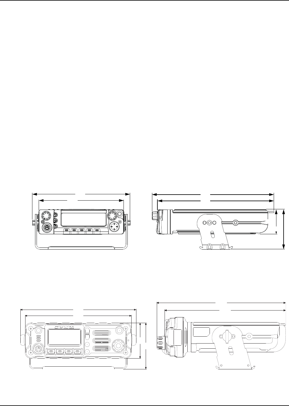
Figure 1-1, Figure 1-2, Figure 1-3 and Figure 1-4 show the basic dimensions of the dash mount
transceiver trunnion APX mobile radio. The transceiver portion of a remote mount APX mobile is
sized similarly.
When installing the radio, make sure to plan the installation carefully and leave additional room in the
rear of the radio for cabling and accessory connections; in the front of the radio for access, controls,
and cabling (if remote mount); and to the sides of the radio so that you may access and install the
trunnion screws/wing screws.
NOTE: The measurement unit used in Figure 1-1 to Figure 1-22 is millimeter.
NOTE: The rear accessory connector adds 0.75 in to the overall length. The remote mount length
is 244 mm.
Figure 1-1. Front View of APX 7500
Mid Power Dash Mount Transceiver and Trunnion
Figure 1-2. Side View of APX 7500 Mid Power
Dash Mount Transceiver and Trunnion
Figure 1-3. Front View of APX 2500/4500
Mid Power Dash Mount Transceiver and Trunnion
Figure 1-4. Side View of APX 2500/4500
Mid Power Dash Mount Transceiver and Trunnion
206
180
256
244
51
83
224
206
69
89
222
209
6878215A01
1-2 Introduction Mobile Radio Description
NOTE: The rear accessory connector adds 0.75 in to the overall length. The remote mount length
is 194mm.
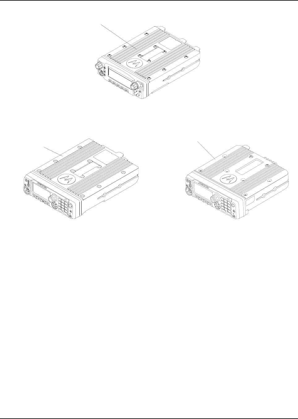
Figure 1-5. Front View of APX 7500
High Power (100W) Transceiver and Trunnion
Figure 1-6. Side View of APX 7500 High Power (100W)
Transceiver and Trunnion
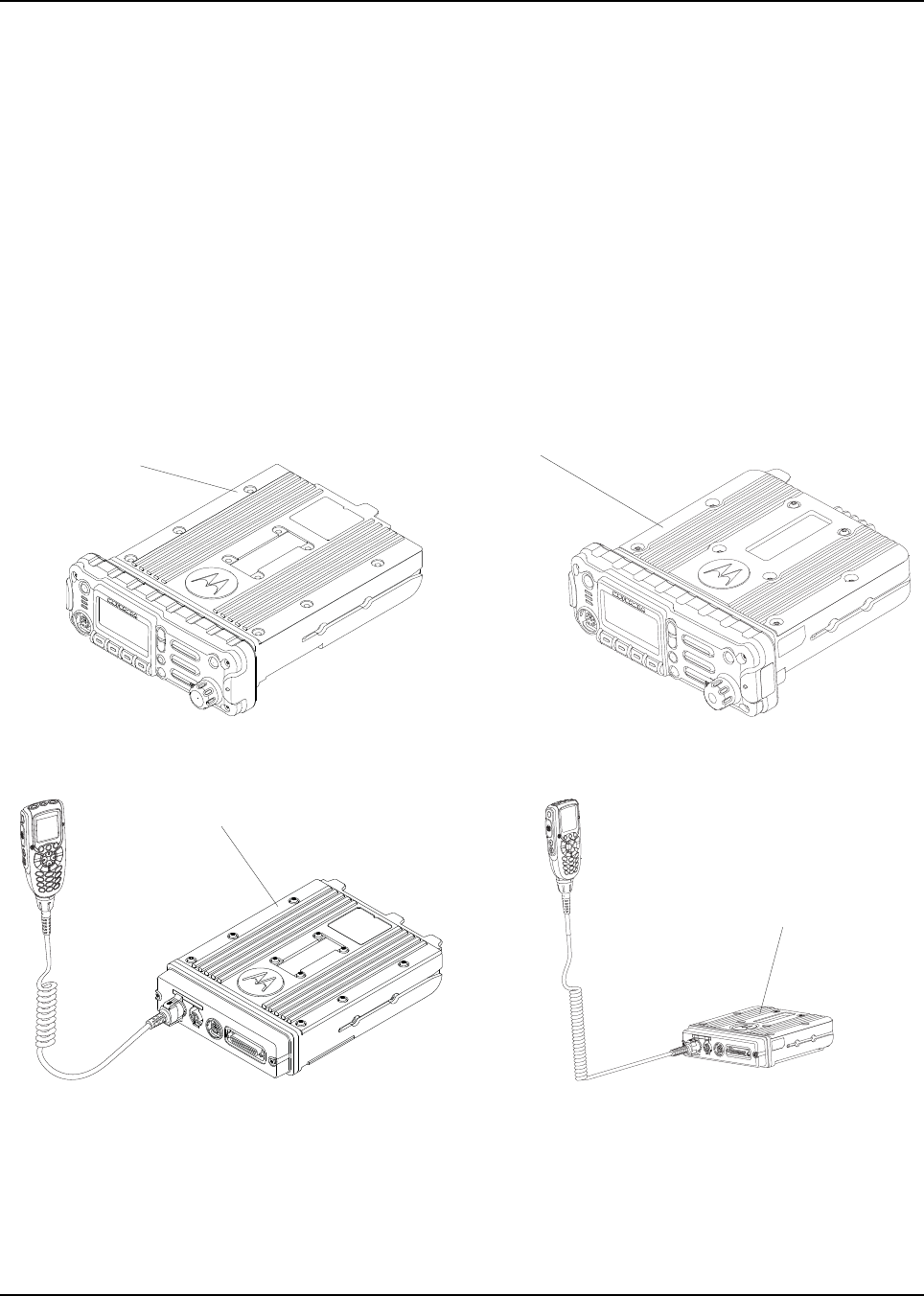
Figure 1-7. Front View of O2 Control Head
Attached to APX 7500 Mid Power Dash Mount
Transceiver and Trunnion
Figure 1-8. Side View of O2 Control Head
Attached to APX7500 Mid Power Dash Mount
Transceiver and Trunnion
Figure 1-9. Front View of O7 Control Head
Attached to APX 2500 Mid Power Dash Mount
Transceiver and Trunnion
Figure 1-10. Side View of O7 Control Head
Attached to APX 2500 Mid Power Dash Mount
Transceiver and Trunnion
223
74
90
293
206
92
69
278
269
207
194
51
80
178
51
224
6878215A01
Introduction Mobile Radio Description 1-3
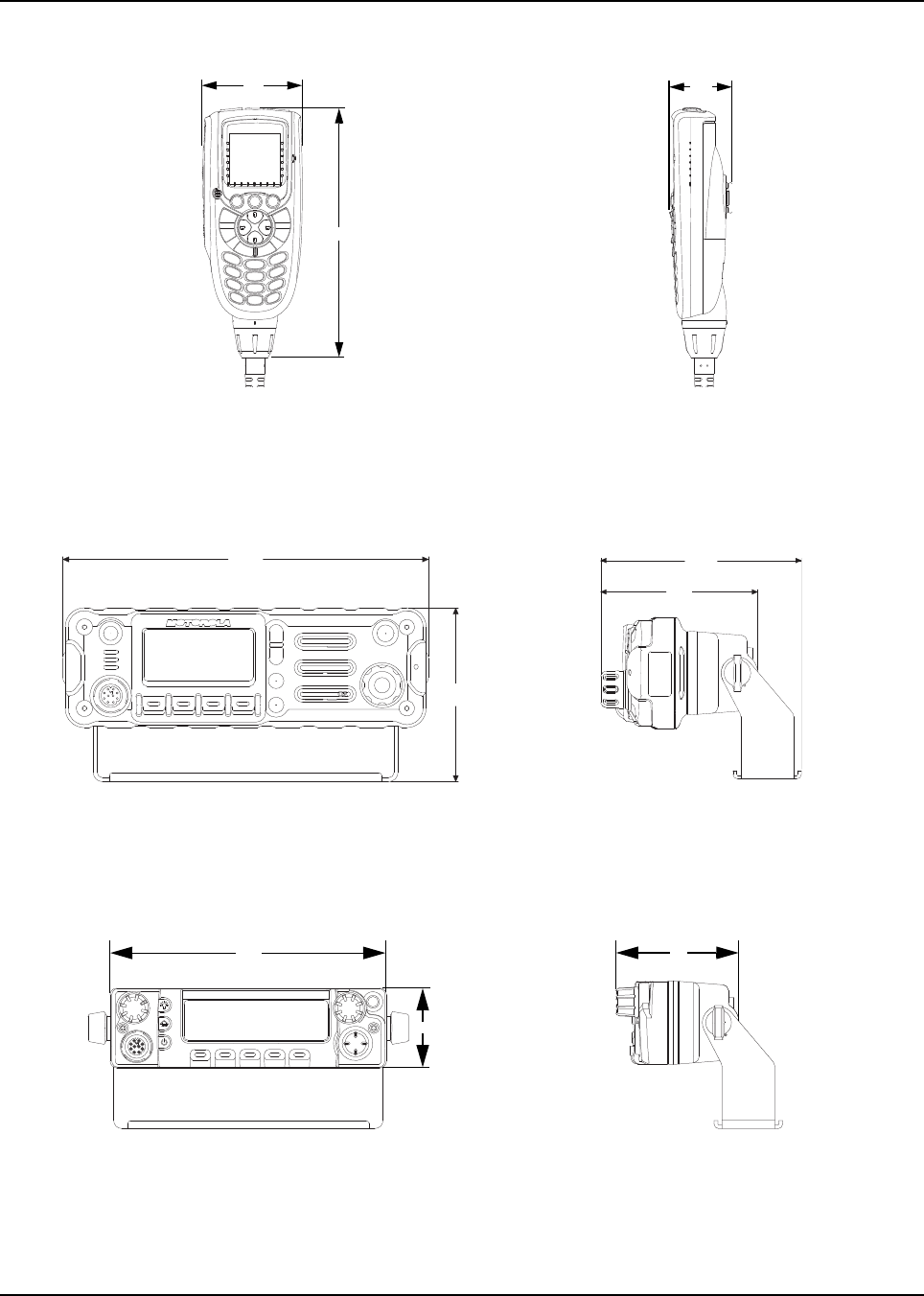
Figure 1-11. Front View of O3 Control
Head with Coiled Cable
Figure 1-12. Side View of O3 Control
Head with Coiled Cable
Figure 1-13. Front View of O2 Control Head with
Remote Mount and Trunnion
Figure 1-14. Side View of O2 Control Head with
Remote Mount and Trunnion
Figure 1-15. Front View of O5 Control Head with
Remote Mount and Trunnion
Figure 1-16. Side View of O5 Control Head with
Remote Mount and Trunnion
61
153
38
209
99
123
97
51
180 75

6878215A01
1-4 Introduction Mobile Radio Description
Figure 1-17. Front View of O7 Control Head with
Remote Mount and Trunnion
Figure 1-18. Side View of O7 Control Head with
Remote Mount and Trunnion
Figure 1-19. Front View of O9 Control Head with
Trunnion
Figure 1-20. Side View of O9 Control Head with
Trunnion
Figure 1-21. Top View of O9 Universal
Relay Controller with Trunnion
(URC is an orderable accessory.)
Figure 1-22. Side View of O9 Universal
Relay Controller with Trunnion
(URC is an orderable accessory.)
209
178
91
108
82
178
190 83
185
210
61.5
6878215A01
Introduction Standard Configurations 1-5
1.2 Standard Configurations
1.2.1 Dash Mount Configuration
NOTE: The dash mount configuration is not applicable for 100W radios and O9 control heads.
There are two versions of the APX mobile dash mount. The first are the O2, O5 and O7 control
heads which are mounted on the front of the transceiver housing. The second is the O3 control head
which is connected to the transceiver via a coiled cable, which is plugged into the CAN connector on
the transceiver.
Electrical connection between the two takes place within the radio via a flexible circuit board
between the connectors on the front of the transceiver and at the back of the control head for O2, O5
and O7 and between the connectors on the front of the transceiver and at the back of the TIB for the
O3.
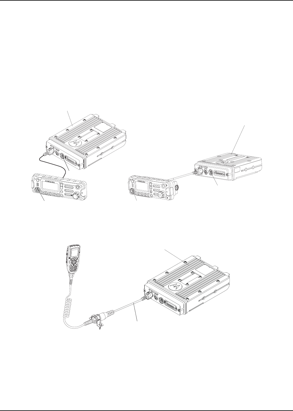
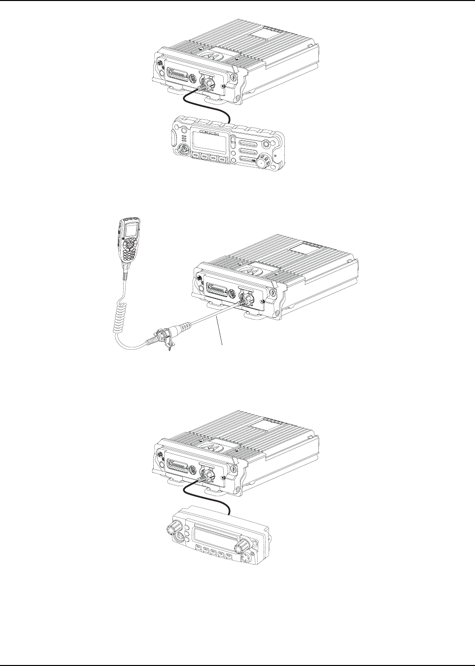
Figure 1-23. Dash Mount Configuration for O2 Control Head
Figure 1-24. Dash Mount Configuration for O3 Control Head
ASTRO 25 Subscribers
APX 2500
ASTRO 25 Subscribers APX 5500/
APX 6500/APX 7500/
APX 6500 Li Mobile
ASTRO 25 Subscribers
APX 2500/APX 4500
ASTRO 25 Subscribers APX 5500/
APX 6500/APX 7500/
APX 6500 Li Mobile
6878215A01
1-6 Introduction Standard Configurations
For details on this configuration, see Section 2.2.1 on page 2-21.
Figure 1-25. Dash Mount Configuration for O5 Control Head (Only Applicable for ASTRO 25 Subscribers
APX 5500/APX 6500/APX 7500/APX 6500 Li Mobile)
Figure 1-26. Dash Mount Configuration for O7 Control Head
ASTRO 25 Subscribers APX 5500/
APX 6500/APX 7500/
APX 6500 Li Mobile
ASTRO 25 Subscribers
APX 2500
ASTRO 25 Subscribers APX 5500/
APX 6500/APX 7500/
APX 6500 Li Mobile
6878215A01
Introduction Standard Configurations 1-7
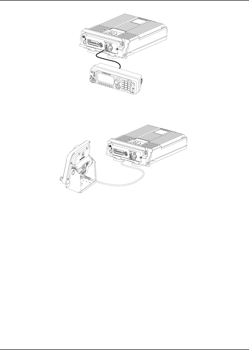
1.2.2 Remote Mount Configuration
In the remote control version, the transceiver and the control head are mounted separately in the
vehicle. The O2, O5 and O7 control heads are mounted in remote trunnions near the operator.The
O3 and O9 control heads are also mounted near the operator using extension cables. The
transceiver and control head are mounted using a trunnion or other mounting hardware. If the
transceiver is located in a car trunk, ensure that it is mounted securely and that sufficient cooling is
provided. Do not cover the transceiver with baggage, blankets, etc.
NOTE: The keypad mic should only be plugged into the Modified Modular Plug (MMP) connector
located on the control head, in either dash mount or remote mount configuration.
Figure 1-27. Remote Mount Configuration with Mid Power Transceiver, Transceiver Interface Board,
CHIB Rear Assembly and O2 Control Head
Figure 1-28. Remote Mount Configuration with Mid Power Transceiver,
Transceiver Interface Board and O3 Control Head
MMP
MMP
ASTRO 25 Subscribers APX 5500/
APX 6500/APX 7500/
APX 6500 Li Mobile
ASTRO 25 Subscribers
APX 2500/APX 4500
MMP
MMP
5 m (17 ft) Extension Cable
ASTRO 25 Subscribers APX 5500/
APX 6500/APX 7500/
APX 6500 Li Mobile
6878215A01
1-8 Introduction Standard Configurations
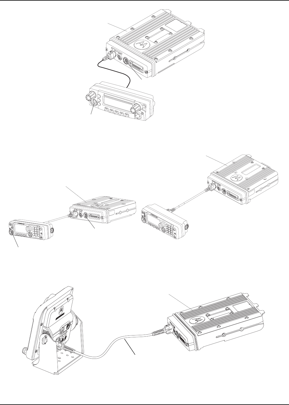
Figure 1-29. Remote Mount Configuration with Mid Power Transceiver, Transceiver Interface Board,
CHIB Rear Assembly and O5 Control Head
Figure 1-30. Remote Mount Configuration with Mid Power Transceiver,
Transceiver Interface Board, CHIB Rear Assembly and O7 Control Head
Figure 1-31. Remote Mount Configuration with Mid Power Transceiver,
Transceiver Interface Board and O9 Control Head
MMP
MMP
ASTRO 25 Subscribers APX 5500/
APX 6500/APX 7500/
APX 6500 Li Mobile
MMP
MMP
ASTRO 25 Subscribers APX 5500/
APX 6500/APX 7500/
APX 6500 Li Mobile
ASTRO 25 Subscribers
APX 2500
17 ft Extension Cable
ASTRO 25 Subscribers APX 7500
6878215A01
Introduction Standard Configurations 1-9
Figure 1-32. Remote Mount Configuration with High Power (100W)
Radio Transceiver and O2 Control Head
Figure 1-33. Remote Mount Configuration with High Power (100W)
Radio Transceiver and O3 Control Head
Figure 1-34. Remote Mount Configuration with High Power (100W)
Radio Transceiver and O5 Control Head
5 m (17 ft) Extension Cable
6878215A01
1-10 Introduction Standard Configurations
Figure 1-35. Remote Mount Configuration with High Power (100W)
Radio Transceiver and O7 Control Head
Figure 1-36. Remote Mount Configuration with High Power (100W)
Radio Transceiver and O9 Control Head
6878215A01
Introduction Standard Configurations 1-11
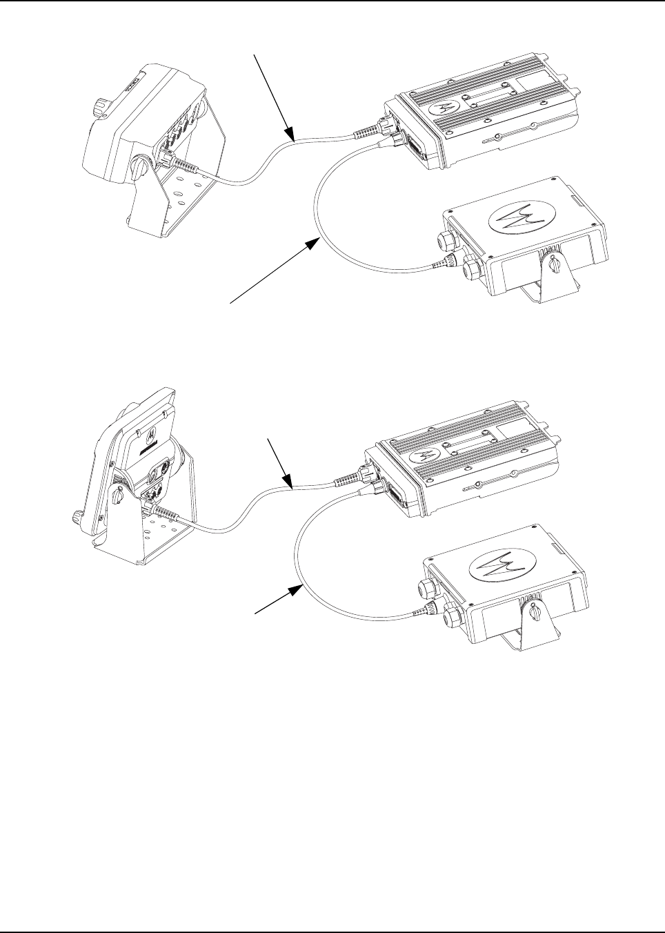
Figure 1-37. Remote Mount Configuration with Mid Power Radio Transceiver,
Universal Relay Controller and O7 Control Head (URC is optional.)
Figure 1-38. Remote Mount Configuration with Mid Power Radio Transceiver,
Universal Relay Controller and O9 Control Head (URC is optional.)
17 ft Extension Cable
O7 to URC Cable
O9 to URC Cable
17 ft Extension Cable
6878215A01
1-12 Introduction Standard Configurations
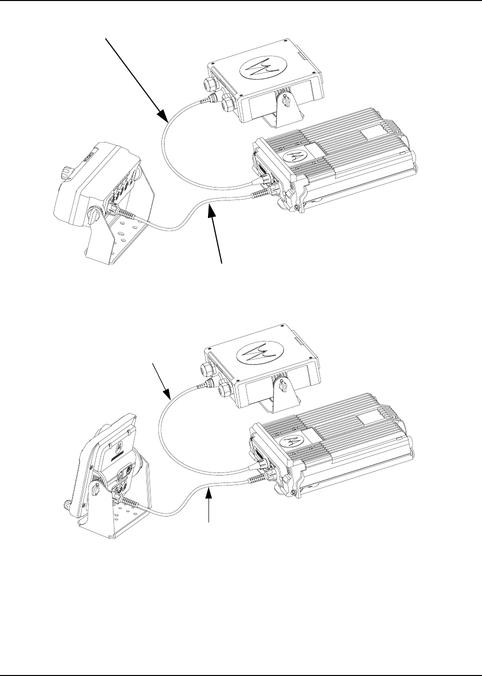
Figure 1-39. Remote Mount Configuration with High Power (100W) Radio Transceiver,
Universal Relay Controller and O7 Control Head (URC is optional.)
Figure 1-40. Remote Mount Configuration with High Power (100W) Radio Transceiver,
Universal Relay Controller and O9 Control Head (URC is optional.)
For details on these configurations, see Section 2.2.2 on page 2-23.
O7 to URC Cable
17 ft Extension Cable
O9 to URC Cable
17 ft Extension Cable

6878215A01
Introduction Standard Configurations 1-13
1.2.3 Multi Control Head
The multi control head option allows separate, remotely operated control heads to operate and
control the radio. For example, a fire truck could have a control head located in the cab and on the
rear of the truck so that the radio could be operated from outside the vehicle.
NOTE: The dual control head can be used together in the future.

6878215A01
1-14 Introduction Motorcycle Configurations
1.3 Motorcycle Configurations
NOTE: The motorcycle configurations are not applicable for 100W radios and O9 control heads.
The ASTRO APX mobile motorcycle radio models provide most of the equipment needed for
installing a standard ASTRO APX mobile radio on a motorcycle. Most of this radio system is
standard equipment. See Chapter 5: Motorcycle Radio Installation for further information.
1.4 Base/Control Stations
NOTE: The base/control station option is not applicable for 100W radios and O9 control heads.
If mobile radio equipment is installed at a fixed location and operated as a control station or as a
fixed unit, the antenna installation must comply with the following requirements in order to ensure
optimal performance and compliance with the RF energy exposure limits in the standards and
guidelines listed in the 6881095C99 manual:
• The antenna should be mounted outside the building on the roof or a tower if at all possible.
• As with all fixed site antenna installations, it is the responsibility of the licensee to manage the
site in accordance with applicable regulatory requirements and may require additional
compliance actions such as site survey measurements, signage, and site access restrictions in
order to ensure that exposure limits are not exceeded.
1.5 Tools Required for APX Mobile Installations
Tool Part Number
10 mm wrench –
5 mm Allen wrench –
Rubber-coated pliers –
Regular slot screwdriver of Phillips #2 –
Pin removal tool 6680163F01
RF antenna tool HLN6695_
Wing screw torque tool HLN6970_

Chapter 2 Standard Configurations
2.1 Planning the Installation
The APX mobile radio operates only in negative ground electrical systems with a valid operating
range of 10.8VDC to 16.3VDC. Before starting the radio installation, make sure that the ground
polarity of the vehicle is correct. Accidentally reversing the polarity will not damage the radio, but will
cause the cable fuses to blow.
Planning is the key to fast, easy radio installation. Before starting the installation, inspect the vehicle
and determine how and where you intend to mount the antenna, radio, and accessories. Plan wire
and cable runs to provide maximum protection from inching, crushing, and overheating.
Before installing any electrical equipment, check the vehicle manufacturer’s user
manual for warnings or recommendations.
The installation of this device should be completed by an authorized servicer or
installer. Failure to properly install the device may result in damage to the device, or
improper operation.
!
C a u t i o n
6878215A01
2-2 Standard Configurations Planning the Installation
2.1.1 Installation Examples
The mobile two-way radio offers various methods of installation, with accessories placed to the
vehicle as desired. The radio can be a dash or remote mount except for the 100W radio or with 09
control head, which can only be mounted remotely. The O9 control head with the radio and the URC
can only be mounted remotely (see Figure 2-3).
Figure 2-1. Dash Mount Radios Can Be Located in the Middle Console, on the
Transmission Hump, or Under the Dash (See Figure 2-2 for 100W Radio Install)
Figure 2-2. Remote Mount Radio Control Heads Can Be Located in the Middle
Console, on the Transmission Hump, or Under the Dash
Figure 2-3. Remote Mount of the Radio, O9 Control Head
and Universal Relay Controller (URC is optional.)
NOTE: 100W radio install is typically at the rear vehicle compartment.
911
Antenna
1/4-Wavelength
Radio
Speaker
Battery Radio
911
Antenna
1/4-Wavelength
Control
Head
Speaker
Battery Control
Head
Radio
911
Antenna
1/4-Wavelength
Control Head
Speaker
Battery
Universal Relay
Controller Box
Radio
Siren Speaker Siren Box

6878215A01
2-14 Standard Configurations Planning the Installation
2.1.3 Radio Operation Wiring for Dash and Remote Configurations
Determine from Table 2-1, Table 2-2, or Table 2-3 the radio functionality you wish to achieve, which is
controlled by the vehicle’s ignition switch state, the physical wiring of the radio’s ignition sense (ACC)
wire, and by the programmed CPS setting. For additional radio functionality as determined by the
programming of the ignition switch in CPS, refer to the HELP menu in your CPS (i.e. Ignition as:
Required, Blank, Soft Power Off, TX Inhibit, PTT TX Inhibit, Ignition Only Power Up).
Choose a clean ignition point which is not shared in the immediate vicinity by other high current
accessories/devices. This will help to reduce the transients on the ignition line. Examples of
high-current accessories/devices are: Air Horn, relays, lightbars and etc. It is recommended to wire
to the vehicle’s ACC line, not the START or the solenoid side of the ignition circuit. Refer to chapter 6
for best installation practices. The Ignition sense (ACC) cable uses either a 3-amp fuse
(6580283E01) or 4-amp fuse (6580283E02).
2.1.3.1 Dash Mount: Power, Ignition, and Emergency Cable Installation
The standard dash mount rear ignition sense cable HLN6863 contains a “thin red” ignition wire, a
jumper wire that shorts emergency to ground, and two gray wires attached to an external speaker
plug. The thin RED wire is the ignition sensed wire. Refer to Table 2-1, Table 2-2, or Table 2-3 for its
correct wiring configurations.
NOTE: This cable MUST be attached in order for the radio to operate in Dash mount, regardless of
how emergency is programmed in CPS or wired inside the vehicle. Either the emergency
jumper wire or an emergency accessory (footswitch or button) must be wired to the rear of the
transceiver in Dash mount. Otherwise, upon attachment of the radio’s power cable to the
vehicle battery, the radio will incorrectly determine that emergency operation has been
activated, such as when an emergency footswitch is de-pressed and the emergency pin is
ungrounded.

6878215A01
Standard Configurations Planning the Installation 2-15
2.1.3.2 Remote Mount: Power, Ignition, and Emergency Cable Installation
The single control head O2, O5, O7 or O9 remote mount configurations receive power from the J200
connector’s red and black wires. The yellow wire at J200 is one ignition sense wire. On mid power
radios, the J2 and J600 connectors can also be used for ignition sense. On high power radios, the
J200 yellow wire or the J600 connector can be used for ignition sense. If the HLN6863 is attached at
J100 of the O2, O5, O7 or O9 control head, the “thin red” wire will NOT function as an ignition sense
wire, since the J100 connector has no ignition sense electrical connection.
NOTE: It is incorrect for installation to attach ignition sense at more than one wire or connector.
Refer to Table 2-1 or Table 2-2 for its correct wiring configurations.
The O3 control head receives its power down the CAN cable, and detects the ignition state by the
ignition sense pin at either J2 or J600. On mid power radios, the J2 and J600 connectors can also be
used for ignition sense. On high power radios, only the J600 connector can be used for ignition
sense.
In Multi-Control Head installations, the yellow ignition wire must be connected to the head assigned
ID # 1. See Section 2.2.2.5 “Setting the Initial Control Head ID” on page 2-29 for further information.
In remote mount O2, O3, O5, O7 or O9, an Emergency jumper to ground is placed by default on the
TIB (JU344) so that there is no need to attach a cable with an emergency accessory at either J2 or at
J600. This jumper must be removed if an emergency accessory (footswitch or button to Ground) is
installed at either J2 or J600 (or J626 on the accessory cable) locations. If the jumper JU344 is
removed but no emergency accessory is installed, the radio will power-up incorrectly into emergency
mode all the time. Refer to Figure 4-3 for details.
The design of the control head is different compared to the transceiver, therefore it is also NOT
necessary to attach HLN6863 at J100 to prevent accidental emergency operation. The control head
uses an edge-detect, not a state-detect like on the transceiver, so mounting of HLN6863 is not
mandatory.

6878215A01
2-16 Standard Configurations Planning the Installation
Table 2-1. Dash O2, O5 or O7 Radio Operations Dependent Upon A+ and Ignition Connections
Dash Mount
Transceiver
Red Power
Wire
HLN6863
Thin Red Wire
Transceiver
Red Power
Wire
HLN6863
Thin Red Wire
Transceiver
Red Power
Wire
HLN6863
Thin Red Wire
Connected to
battery
XXX X
Connected to
ignition switch
XXX
Ignition switch
controls
No ignition switch control. Enables ignition switch functionality
as programmed in the codeplug.
Illegal wiring configuration. See
CAUTION note.
Table 2-2. Remote O2, O5, O7, or O9 Radio Operations Dependent Upon A+ and Ignition Connections
Remote
Mount
Control Head
Red Wire
Control Head
Yellow Wire
Control Head
Red Wire
Control Head
Yellow Wire
Control Head
Red Wire
Control Head
Yellow Wire
Connected to
battery
XXX X
Connected to
ignition switch
XXX
Ignition switch
controls
No ignition switch control. Enables ignition switch functionality
as programmed in the codeplug.
Illegal wiring configuration. See
CAUTION note.
Table 2-3. Remote O2, O5, O7 or O9 Radio Operations Dependent Upon A+ and Ignition Connections
Mid Power
Dash/Remote Transceiver
Red Power
Wire
HLN6863
Thin Red Wire
at J2 Transceiver
Red Power
Wire
HLN6863
Thin Red Wire
at J2 Transceiver
Red Power
Wire
HLN6863
Thin Red Wire
at J2
High Power
Dash/Remote
HLN6863
Thin Red Wire
at J626
HLN6863
Thin Red Wire
at J626
HLN6863
Thin Red Wire
at J626
Connected to
battery
XXX
Connected to
ignition switch
XXX
Ignition switch
controls
No ignition switch control. Enables ignition switch functionality
as programmed in the codeplug.
Illegal wiring configuration. See
CAUTION note.
DO NOT connect any wires to the battery terminals until you have finished the entire
radio installation (Dash or Remote Mount) configuration to avoid potential equipment
damage.
Incorrect wiring of the radio may result in incorrect ignition sense detection, incorrect
power-on state, or incorrect power-off state of the radio system.
The Control Head Power cable wire (RED) and Transceiver Power cable wire (RED)
are always attached to the battery terminal and NOT to the ignition switch.
!
C a u t i o n

6878215A01
Standard Configurations Planning the Installation 2-17
2.1.4 Ignition Sense Switch (Radio Wide Advance)
CPS selectable settings to control the radio’s functionality based on the state of the vehicle’s Ignition
status.
NOTE: When either TX Inhibit, PTT TX Inhibit or Required are selected, the Emergency Power Up
feature will not be available to the radio-user.
When any other Ignition Switch setting is made, Emergency Power Up is available to the
radio-user, regardless of current ignition state.
Any optional inactivity time-out timer setting in CPS may delay the power off of the radio once
Ignition sense is removed.
Table 2-4. Ignition Sense Switch Settings in CPS
Feature Description
Blank • Radio POWERS ON when the Power Button is pressed or with the emergency power up
feature.
• Radio POWERS OFF when the Power Button is pressed.
TX Inhibit • Radio POWERS ON when the Power Button is pressed or with the emergency power up
feature.
• Radio POWERS OFF when the Power Button is pressed.
•If IGNITION is not present all transmissions are inhibited.
• The radio will not affiliate with trunking systems and therefore CANNOT receive any
trunking dispatch communications.
• Emergency Alarm transmissions are NOT possible with the use of the emergency power
up feature.
PTT TX Inhibit • Radio POWERS ON when the Power Button is pressed or with the emergency power up
feature.
• Radio POWERS OFF when the Power Button is pressed.
•If IGNITION is not present all transmissions are inhibited.
• The radio is able to affiliate with trunking systems. The radio can ONLY receive trunking
dispatch communications.
• Emergency Alarm transmissions are possible with the use of the emergency power up
feature.
Required • Radio POWERS ON when the Power Button is pressed and Ignition is present.
• Radio POWERS ON when Ignition is cycled and radio was previously ON.
• Radio POWERS OFF when the Power Button is pressed, or when Ignition is lost.
Soft Power Off • Radio POWERS ON when the Power Button is pressed, or when Ignition is detected.
• Radio POWERS OFF when the Power Button is pressed, or when Ignition is lost.
Ignition Only Power Up • Radio POWERS ON when Ignition is present.
• Radio POWERS OFF when Ignition is lost.
• Control head power button is ignored.
6878215A01
2-18 Standard Configurations Planning the Installation
2.1.5 Siren/PA Configuration/Programming
The Siren/PA is shipped pre-wired for 100W operation. It can be rewired for 65W, 75W, or 130W
power levels.
To change to another power level, perform the following:
1. Open the Siren/PA connector cover to gain access to the two-connector speaker leads. Do
not change the speaker common lead (pin 20). The other lead is connected to pin 35 (for
100W operation).
2. Using an appropriate pin removal tool, extract pin 35 and move it to one of the following pin
locations:
- pin location 36 for 75W operation
- pin location 28 for 65W or 130W operation
3. For 65W or 75W operation, no further changes are required. Reassemble the connector.
4. For 130W operation, you must parallel two 11 speakers, each rated at 65W minimum.
Proper phasing of the two speakers is important--when connecting two speakers in parallel,
wire similar speaker terminals together to ensure maximum loudness and prevent
"deadspots." For example, if the terminals are marked "1" and "2", connect the terminals
marked "1" together and connect those wires to one speaker lead. Connect the terminals
marked "2" together and connect those wires to the other speaker lead.
5. When the Siren/PA is configured for dual speaker, 130W operation, it is necessary to remove
a resistor and move two jumpers to set the correct power level. Remove the Siren/PA cover,
and locate resistor R219 (0 ohm). This resistor should be removed for 130W operation.
Locate jumpers JU100 and JU101. These jumpers should be installed for 130W operation.
6. Close and reconnect the Siren/PA connector cover.
NOTE: Jumpers JU100 and JU101 do not affect the Siren output level. JU100 and JU101
compensate for the lower speaker load and the two speakers in parallel, by
decreasing the gain U102-1. JU100 affects the radio PA level and JU101 affects the
PA audio level.
Pin locations of various power level configurations are listed in Table 2-5
Before continuing, remember that under a high-line supply condition
(16.6V), up to 30% more power will go to the speaker(s) after
reconfiguring for 130W operation. Do this only when your PA
speakers are capable of handling the extra power.
Table 2-5. Power Level Configurations
Pin location of speaker
leads R219 JU100/JU101
65W 20,28 IN Across pins A and B
75W 20,36 IN Across pins A and B
100W 20,35 IN Across pins A and B
130W 20,28 OUT Across pins B and C
!
C a u t i o n
6878215A01
Standard Configurations Radio Mounting 2-19
2.2 Radio Mounting
The mounting location must be accessible and visible. Select a location that will permit routing the
RF antenna cable as directly as possible.
NOTE: For optimum radio performance, orient the mounting trunnion as shown in Figure 2-22 or
Figure 2-23 for mid power and Figure 2-24 for high power. For new or existing installations of
all but 100W radios, use only the APX mobile trunnion, kit number HLN7002_except for APX
2500 and APX 4500 which shall use the trunnion with kit number HLN6861_. For new or
existing installations of 100W radios, use only the APX mobile trunnion, kit numbers
HLN7003_.
Figure 2-22. APX 7500/ APX6500/ APX5500/ APX6500Li Mid Power Trunnion Orientation
(Cannot Be Used for 100W Radios)
DO NOT mount the radio on a plastic mounting surface without first reinforcing the
mounting surface; the weight of the radio may crack or break the mounting surface.
DO NOT mount the radio on a flat or concave surface where the radio could be
partially submersed in water. This is especially important if the cab area of the vehicle
is cleaned by spraying with water. If the radio sits in water for a length of time, moisture
may seep inside the radio and damage the electronic components.
DO NOT allow water to stand in recessed areas of vertically mounted radios. Remove
any moisture immediately to prevent it from seeping down into the radio.
Care must be taken to shield the control head (front and back) from direct exposure to
pressurized water. The pressurized water from a hose, in most cases, is more severe
than the stated test and conditions in typical environments.
!
C a u t i o n
RADIO FRONT
APPLIES TO RADIOS IN DASH AND REMOTE INSTALLATIONS
6878215A01
2-20 Standard Configurations Radio Mounting
Figure 2-24. Trunnion Orientation for 100W Radios
Figure 2-23. APX 2500/APX4500 Mid Power Trunnion
Orientation (Cannot Be Used for 100W Radios)
RADIO FRONT

6878215A01
Standard Configurations Radio Mounting 2-21
2.2.1 Dash Mount with Trunnion
NOTE: This configuration is not applicable for 100W radios.
1. Referring to Figure 2-6, select the suitable trunnion kit per the type of mid power transceiver.
2. Select the location to mount your radio on the transmission hump (see Figure 2-25) or under
the dash (see Figure 2-26).
NOTE: When mounting the trunnion on the transmission hump take care the transmission housing is
not affected. Plan your installation ensuring enough room for the Accessory connector and
cable in the back of the radio.
3. Using the trunnion mounting bracket as a template, mark the positions of the holes on the
mounting surface. Use the innermost four holes for a curved mounting surface such as the
transmission hump, and the four outmost holes for a flat surface such as under the dash.
4. Center punch the spots you have marked and realign the trunnion in position.
5. Secure the trunnion mounting bracket with the four self-drilling screws provided
(see Figure 2-25 and Figure 2-26).
6. Ensure that the plastic guides are aligned (horizontal) to the grooves of the trunnion. Slide the
radio into the grooves until it snaps into place (see Figure 2-26).
Table 2-6. Mid Power Trunnion Kit
Item Part Number Description Mid Power Transceiver
1
0371859H01 Trunnion Mounting Screw APX 5500/APX 6500/APX 6500 Li/APX 7500
0305760W02 Trunnion Mounting Wing Screw APX 2500/APX 4500
2 0312002B14 Self-Drilling Tapping Screw
APX 5500/APX 6500/APX 6500 Li/APX 7500
APX 2500/APX 4500
3
HLN7002_ Mackinaw Trunnion Hardware Kit APX 5500/APX 6500/APX 6500 Li/APX 7500
HLN6861_ Millenium Trunnion Hardware Kit APX 2500/APX 4500
6878215A01
2-22 Standard Configurations Radio Mounting
Figure 2-25. Transmission Hump Trunnion Mounting
Figure 2-26. Below Dash Trunnion Mounting
7. Secure the radio with two screws provided (Item 1 in Table 2-6). The torque down force for
0371859H01 should be between 50in-lbf to 52in-lbf.
8. For screw 0305760W02, the wing screw torque tool (HLN6970_) is designed to securely
tighten the trunnion wing screws while installing the radio. The tool can also be used to
loosen the wing screws. Detailed instructions are included in the tool packaging.
NOTE: This configuration shows the O5 control head. The TIB is used for O3 control head for the
same configuration.
Tabs
Threaded Hole
for Screw
Groove
Plastic
Guides
1
32
1
1
1
3

6878215A01
Standard Configurations Radio Mounting 2-23
2.2.2 Remote Mount with Trunnion
For a remote mount installation, the transceiver may be mounted anywhere in the vehicle, provided
that the installation location is safe, follows the cautions mentioned at the beginning of this section,
and is accessible for servicing/maintenance as well as cabling. A typical mounting location
recommended by Motorola is in the vehicle’s trunk. The trunnion provided may still be used to mount
the transceiver, and the mounting process is the same as for the dash mount installation
(Section 2.2.1 on page 2-21). However, for 100W radios you must follow the procedure detailed
below in Section 2.2.2.1. See Figure 2-10, Figure 2-11, Figure 2-13, or Figure 2-14 for a remote
installation.
Before installing any electrical equipment, check the vehicle manufacturer’s user
manual.
The installation of this device should be completed by an authorized servicer or
installer.
Before making any holes in the trunk for radio mounting, check the vehicle
manufacturer's user manual for restrictions (e.g. due to the gas tank location).
!
C a u t i o n
6878215A01
2-24 Standard Configurations Radio Mounting
2.2.2.1 100W Radios Only
NOTE: Cabling to the front of the radio (TIB) should not be completed with the handle opened as it is
needed to be removed to close the handle. It is suggested that the cabling is to be attached
to the front of the radio after the radio is assembled into the trunnion.
1. After selecting the mounting location, use the trunnion mounting bracket as a template and
mark the positions of the holes on the mounting surface.
2. Center-punch the spots you have marked and realign the trunnion in position.
3. Secure the trunnion mounting bracket with the four self-drilling screws provided
(see Figure 2-27).
4. After the trunnion has been mounted in the vehicle using the screws provided, install the
radio. Place the radio with the lock handle fully opened on the trunnion, oriented at least
10 mm in front of the rear catches. Push the radio towards the rear catches. The radio is lifted
up slightly and then drops back down, flushed with the trunnion, and stops against the rear
catches. Once this occurs, close the lock handle. Rotate the handle towards the top of the
radio until it is locked in place. The key is not needed in the lock to close the handle, but is
needed to reopen. The keys can only be removed from the lock when it is in the locked
position.
Figure 2-27. 100W Radio Mounting into Quick Release Trunnion
2.2.2.2 Remote Mount Control Head Installation
Choose a mounting location for the radio, considering accessibility, and control and antenna cable
lengths.
The recommended mounting surfaces for the control unit are under the mounting surface, on the
transmission hump, or on the center console. Figure 2-28 and Figure 2-29 shows how the trunnion,
control head, and cables should be installed for the O2, O5, O7 or O9 control head.
NOTE: Connector-protective covers (i.e. Dust Covers) HLN6980_ are provided with the radio.
They should be installed on exposed connectors for added environmental robustness.
6878215A01
Standard Configurations Radio Mounting 2-25
An adjustable trunnion, which allows a number of mounting positions, is supplied for mounting the
control unit. The installation must not interfere with the operation of the vehicle or its accessories, nor
disturb passenger seating or leg room. The control head must be within convenient reach and
viewing of the user.
If the trunnion is mounted on a plastic mounting surface, all four mounting screws should penetrate
the mounting surface’s supporting metal frame. If that is not possible, use a metal backing plate (not
supplied) to strengthen the installation. Install the control follows:
1. Use the control unit trunnion as a template to mark the mounting holes; drill 5/32" holes.
If mounting on a plastic surface, use a metal backing plate.
2. Attach the trunnion bracket using all four 10-16" x 5/8" self-tapping screws provided.
3. Temporarily install the control head (adjusting for proper viewing angle) and fasten it to the
trunnion with two wing screws. Test the installation to be sure the control head feels securely
locked in place while you are pressing its buttons.
4. Finish installation by fully tightening screws.
Figure 2-28. O5 Control Head Installation Exploded View
(Also applicable for O2 and O7 Control Heads)
Metal Backing Plate
(Not Supplied)
6878215A01
2-26 Standard Configurations Radio Mounting
Figure 2-29. O9 Control Head Installation Exploded View
Figure 2-30. O5 Control Head Rear View
(Also applicable for O2 and O7 Control Heads)
ADJUST THE CONTROL HEAD TO
DESIRED ANGLE AND SECURE
WITH WING SCREWS
USE FOUR MOUNTING SCREWS
ON ALL INSTALLATIONS
TRUNNION
DRILL FOUR 5/32'' HOLES
IN MOUNTING SURFACE
MOUNTING SURFACE
IMPORTANT
USE A METAL BACKING PLATE
(NOT SUPPLIED) IF MOUNTING
TRUNNION ON PLASTIC OR
UNSTABLE SURFACE
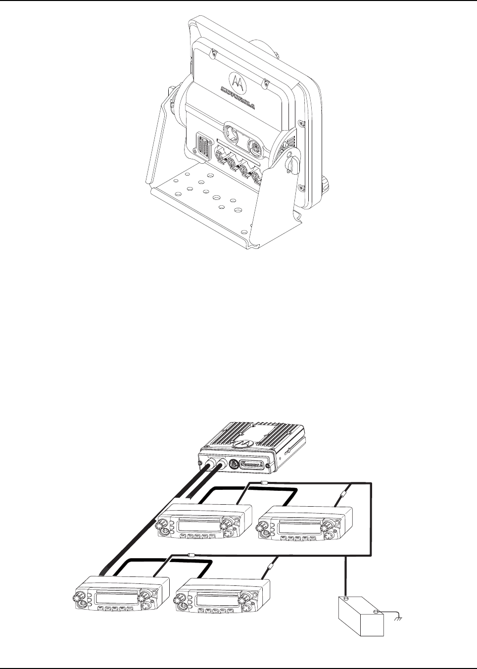
6878215A01
Standard Configurations Radio Mounting 2-27
Figure 2-31. O9 Control Head Rear View
2.2.2.3 Multiple Control Head Installation
Control heads in a multiple control head configuration should be installed per the steps detailed in
Section 2.2.2.2: “Remote Mount Control Head Installation” on page 2-24. Two heads can be
connected to each of the two CAN connectors on the transceiver, with the remaining heads
connected to one or both of the first two. Control heads can also be connected a “daisy chain”
configuration from a single transceiver CAN connector. See Figure 2-32 for examples.
NOTE: The transceiver must be configured for Multiple Control Head via CPS programming.
Navigate to the “Control Head” tab in the Radio Wide section of CPS, and select “Help” for
further information and tutorials.
Control Head 1 Control Head 2
J300R J300R
J200 J200
J300L
(-)
RED LEAD
(+)
BATTERY
FUSE
FUSE
FUSE
FUSE
Control Head 3 Control Head 4
J300R
J200 J200
J300L
J300R
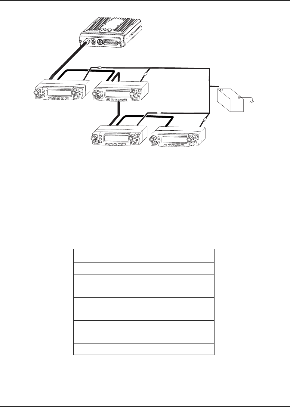
6878215A01
2-28 Standard Configurations Radio Mounting
Figure 2-32. Multiple Control Heads Example Configurations
NOTE: In Multiple Control Head (MCH) installations, the yellow ignition sense wire must be
connected to the head assigned ID # 1. See Section 2.2.2.5 “Setting the Initial Control Head
ID” on page 2-29 for further information.
Use the most convenient configuration for your installation, ensuring that the combined cable lengths
do not exceed 131 feet (40 meters). See Table 2-7 for a list of available CAN cable lengths. Control
head ground, power and ignition sense wires (black, red, and yellow respectively) may need
additional length (not supplied) in installations that locate the head more than 10 feet from a power
source.
Table 2-7. Available CAN Cables
Part Number Description
HKN6164_ Cable, Remote Mount, 40m (131ft)
HKN6165_ Cable, Remote Mount, 35m (115ft)
HKN6166_ Cable, Remote Mount, 23m (75ft)
HKN6167_ Cable, Remote Mount, 15m (50ft)
HKN6168_ Cable, Remote Mount, 9m (30ft)
HKN6169_ Cable, Remote Mount, 5m (17ft)
HKN6170_ Cable, Remote Mount, 3m (10ft)
PMLN4958_ Cable, O3 Extension, 5m (17ft)
Control Head 1 Control Head 2
J300R J300R
J200 J200
J300L J300L
(-)
RED LEAD
(+)
BATTERY
FUSE
FUSE
FUSE
FUSE
Control Head 3 Control Head 4
J300R
J200 J200
J300L
J300R
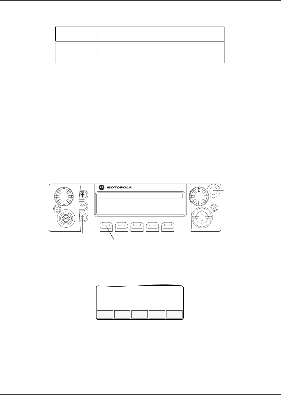
6878215A01
Standard Configurations Radio Mounting 2-29
2.2.2.4 Cable Installation
Route the cables where they are protected from pinching, sharp edges or crushing. Use grommets in
any holes where the cable passes through metal panels. Figure 2-19 shows how the cables and
components are connected. It is not recommended to route cabling or wiring inside the wheel wells
of a vehicle.
2.2.2.5 Setting the Initial Control Head ID
The Front Panel Programming (FPP) mode allows you to define which control head in a Multi Control
Head system becomes control head number 1-4.
Set the control head ID number for each attached head the first time Multi Control Head is used.
1. Press the power button to power off the radio.
2. Press and hold left-most menu and the orange button on the control head simultaneously.
Figure 2-33. APX Mobile O5 Control Head Front View
3. Press the power button to power on the control head. The head will power on into FPP mode
and display the current control head ID number:
Figure 2-34. Radio Display with Current Control Head ID
4. Turn the Mode knob to change the control head’s ID number.
Table 2-8. Ignition Interface Cables
Part Number Description
HLN6863_ Cable, M.A.P. 26pin with Only Ignition and SPK
PMLN4959_ Cable, Y-Splitter with DB-25 and M.A.P. Interface
O5
Left-most
Menu Button
Power Button
Emergency
Button
CH ID#
1
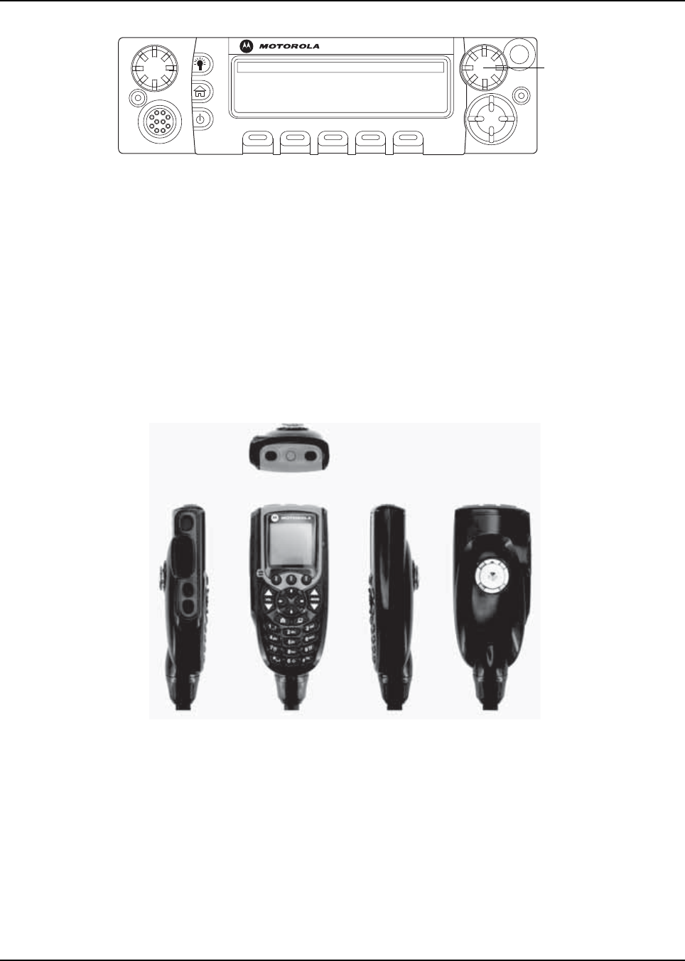
6878215A01
2-30 Standard Configurations Radio Mounting
Figure 2-35. APX Mobile O5 Control Head Front View – Mode Knob
5. Repeat steps 1 to 4 above to set the ID of the remaining control heads.
NOTE: In Multiple Control Head (MCH) installations, the yellow ignition sense wire must be
connected to the head assigned ID # 1.
2.2.2.6 O3 Control Head and Remote Mount Cabling
Choose a mounting location for the radio, considering accessibility, and control and antenna cable
lengths. The control head extension cable and the accessories cable should be installed and routed
properly to avoid complications. Route the cables in the vehicle’s wiring troughs (where available) or
route the cables where they are protected from pinching, sharp edges, or crushing. One suggested
route is along one side of the driveshaft hump under the carpet. Use grommets in any holes where
the cable passes through metal panels.
Figure 2-36. O3 Control Head
The recommended mounting surface for the control unit is on the center console. Figure 2-38 shows
how the hang-up clip control head, and cables should be installed for the O3 control head.
NOTE: Connector-protective covers are provided with the radio. They should be used for added
environmental robustness.
O5
Mode Knob
Top
Front RightLeft Back
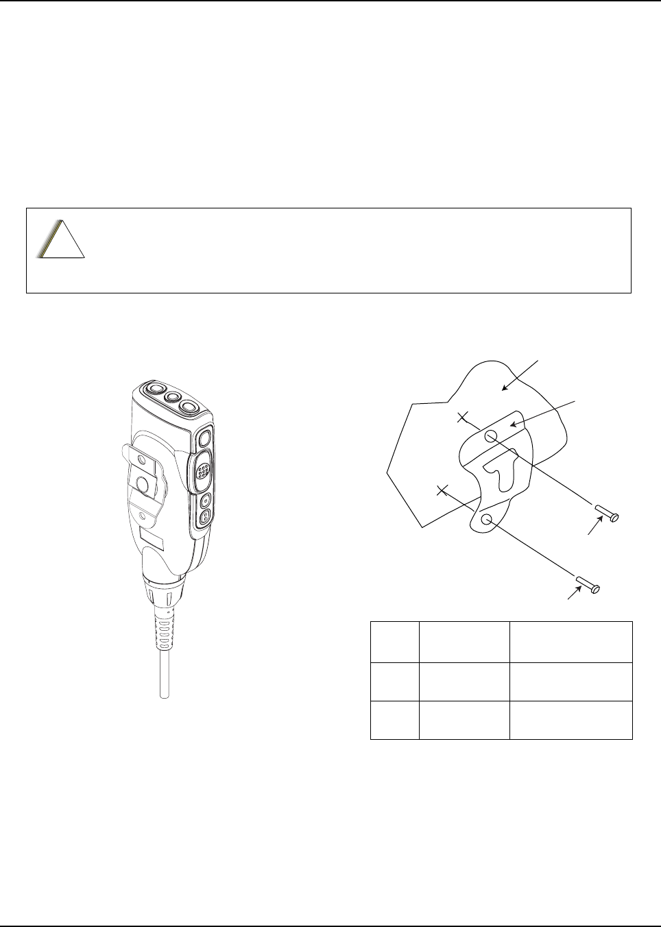
6878215A01
Standard Configurations Radio Mounting 2-31
A mounting clip, which allows the control head to be mounted, is supplied together with the control
head. The installation must not interfere with the operation of the vehicle or its accessories, nor
disturb the passenger seating. The control head must be within convenient reach and viewing of the
user.
Install the mounting clip as follows:
1. Use the provided mounting clip to determine the location of the two screw holes.
2. Drill 7/16” deep holes for upper and lower screws.
3. Use the tapping screw provided to install the mounting clip.
Care must be taken to shield the control head (front and back) from direct exposure to
pressurized water. The pressurized water from a hose, in most cases, is more severe
than the stated test and conditions in typical environments.
Figure 2-37. O3 Control Head Rear View Figure 2-38. Hang-Up Clip Installation
Exploded View
!
C a u t i o n
VEHICLE
DASHBOARD
2
2
1
2
2
1
Vehicle Mounting Surface
Item
No.
Part Number Description
1 01-80743T91 Mic Hang-Up Clip
Assembly
2 03-07644M19 Screw, Machine,
8-32 x 7/16

6878215A01
2-38 Standard Configurations Antenna Installation
2.4 Antenna Installation
IMPORTANT: To assure optimum performance and compliance with RF Energy Safety
standards, these antenna installation guidelines and instructions are
limited to metal-body vehicles with appropriate ground planes and take
into account the potential exposure of back seat passengers and
bystanders outside the vehicle.
NOTE: For mobile radios with rated power of 7 watts or less, the only installation restrictions are to
use only Motorola approved antennas and install the antenna externally on metal body
vehicles. For mobile radios with tuned power greater than 7 watts, always adhere to all the
guidelines and restrictions in Section 2.4.1 below.
2.4.1 Selecting an Antenna Site/Location on a Metal Body Vehicle
1. External installation – Check the requirements of the antenna supplier and install the
vehicle antenna external to a metal body vehicle in accordance with those requirements.
2. Roof top – For optimum performance and compliance with RF Energy Safety standards,
mount the antenna in the center area of the roof.
3. Trunk lid – On some vehicles with clearly defined, flat trunk lids, the antennas of some radio
models (see restrictions below) can also be mounted on the center area of the trunk lid. For
vehicles without clearly defined, flat trunk lids (such as hatchback autos, sports utility
vehicles, and pick-up trucks), mount the antenna in the center area of the roof.
Before installing an antenna on the trunk lid,
- Be sure that the distance from the antenna location on the trunk lid will be at least 85 cm
(33 inches) from the front surface of the rear seat-back to assure compliance with RF
Energy Safety standards.
- Ensure that the trunk lid is grounded by connecting grounding straps between the trunk lid
and the vehicle chassis.
4. Mounting restrictions for certain radio models.
For all VHF and UHF models, the 1/4 wave antenna should be mounted only in the center
area of the roof, not on the trunk lid, to assure compliance with RF Energy Safety
standards.
5. Ensure that the antenna cable can be easily routed to the radio. Route the antenna cable as
far away as possible from any vehicle electronic control units and associated wiring.
6. Check the antenna location for any electrical interference.
If these conditions cannot be satisfied, then mount the antenna on the roof top.
!
C a u t i o n

6878215A01
Standard Configurations Antenna Installation 2-39
7. Ensure that any transmitting radio antennas on this vehicle are separated from each other by
at least 3 feet (0.9 meter). See Figure 2-49.
8. The minimum distance between the antenna and the radio/accessories should be at least
3 feet (91.44 cm).
NOTE: Any two metal pieces rubbing against each other (such as seat springs, shift levers, trunk and
hood lids, exhaust pipes, etc.) in close proximity to the antenna can cause severe receiver
interference.
Figure 2-49. Multiple Antennas Separation
911
3 ft3 ft
3 ft
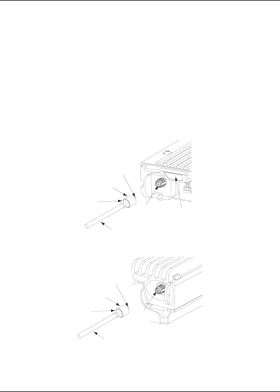
6878215A01
2-40 Standard Configurations Antenna Installation
2.4.2 Mini-UHF Connection
To help aid in the installation of the radio antenna(s), there are labels indicating the frequency. The
first is on the FCC label at the top of the radio which calls out the frequency and by using arrow
points, which side the RF connector of the frequency is located at the back of the radio. The second
is located at the back of the radio, next to the RF connector(s) (see Figure 2-50). To ensure a secure
connection of an antenna cable's mini-UHF plug to a radio's mini-UHF jack, their interlocking
features must be properly engaged. If they are not properly engaged, the system will loosen. Using a
tool (pliers or wrench) will not overcome a poor engagement, and is not recommended.
NOTE: Applying excessive force with a tool can cause damage to the antenna or the connector
(e.g., stripping threads, deforming the collar or connector, or causing the connector to twist in
the housing opening and break).
The mini-UHF connector tool (Motorola part number HLN6695_) is designed to securely tighten the
antenna plug–radio jack connection without damaging either the plug or the jack.
Motorola recommends the following sequence to ensure proper attachment of the system
(see Figure 2-50 and Figure 2-51):
Figure 2-50. Mini-UHF Connection (As Shown on Mid Power)
Figure 2-51. Mini-UHF Connection (100W Radios Only)
1. Make sure that there is sufficient slack in the antenna cable.
2. Make sure that the collar of the antenna cable plug is loose and does not bind.
3. Make sure that the mini-UHF jack is tight in the radio housing.
Coax Conductor
Plug (Pin)
Flange
Cable
Collar Pulled
Back to Flange
Mini UHF
Jack RF Antenna
Connector Label
Coax Conductor
Plug (Pin)
Flange
Cable
Collar Pulled
Back to Flange
Mini UHF
Jack
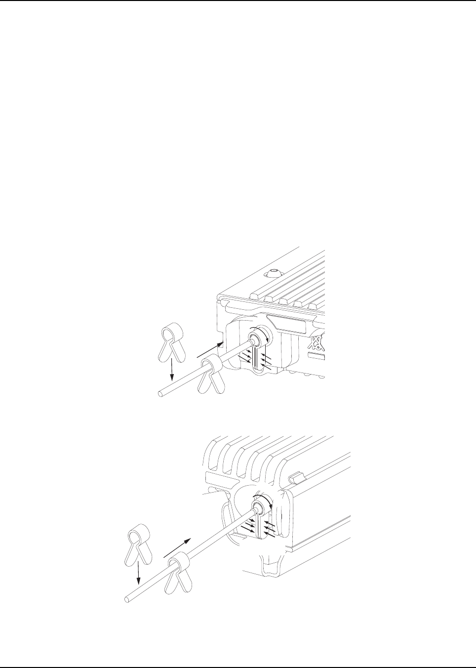
6878215A01
Standard Configurations Antenna Installation 2-41
4. Slide the collar back against the flange. Insert the antenna cable plug’s pin fully into the radio
jack, but do not engage the threads.
5. Ensure that the plug’s and jack’s interlocking features are fully seated. Check this by grasping
the crimp on the cable jack, rotating the cable, and noting any movement. If the features are
seated correctly, there should be NO movement.
6. Finger-tighten the antenna cable plug’s collar onto the radio’s jack.
7. Give a final tug, by hand, to the collar, and retighten by hand as firmly as possible.
8. Slip the mini-UHF connector tool over the coaxial cable, using the gap between the tool’s legs
(see Figure 2-52). Then, slide the tool up onto the plug’s knurled collar. Squeeze the two
straight legs of the tool firmly together between your thumb and index finger and turn
clockwise (as shown) to tighten the collar. It should take 1/4 turn or less. When you feel the
tool slipping on the collar, the connection has been properly tightened. The tool can also be
used to loosen a tight collar.
NOTE: DO NOT use pliers or any other device to grip the tightening tool. It has been designed to
allow you to achieve the proper torque on the collar without overtightening. Overtightening the
collar can damage the connector and the radio.
Figure 2-52. Mini-UHF Connector Tool (As Shown on Mid Power)
Figure 2-53. Mini-UHF Connector Tool (100W Radios Only)
(1) Squeeze
Firmly Together
HLN6695_
(
2
)
T
i
g
h
t
e
n
(1) Squeeze
Firmly Together
HLN6695_
(
2
)
T
i
g
h
t
e
n
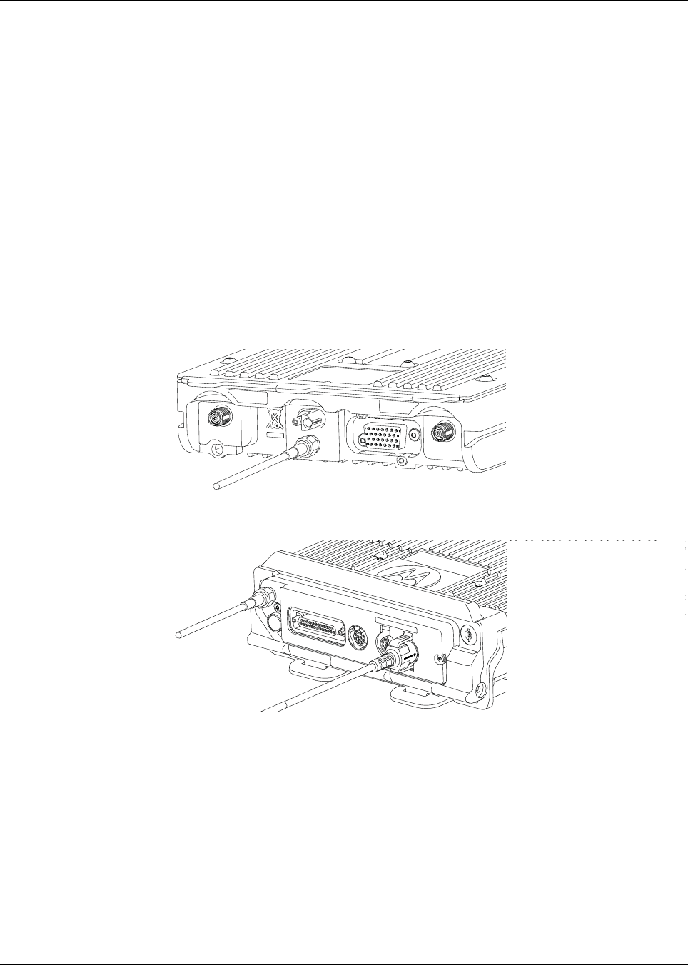
6878215A01
2-42 Standard Configurations Antenna Installation
2.4.3 GPS Antenna Placement
The GPS antenna (excluding the Motorcycle GPS antenna) must be placed at least, 3 feet
(0.9 meters) away from any transmitting antenna, and the antenna must have a clear, unobstructed
view of the sky for best performance. The length of the cabling must be taken into consideration
before the installation is started.
2.4.4 GPS Connection
To ensure a secure connection of the GPS antenna cable's SMA plug to a radio's SMA jack, the
connector must be fully seated. If the connectors are not fully seated, the system will loosen. This
should be done by hand to ensure excess force is not applied. GPS positions as shown in
Figure 2-54 and Figure 2-55 are located in different positions. The mid power radio has the GPS
antenna connector on the back of the radio while the 100W radio has the antenna connector on the
front of the radio.
NOTE: Applying excessive force with a tool can cause damage to the antenna or the connector
(e.g. stripping threads, deforming the collar or connector, or causing the connector to twist in
the housing opening and break).
Figure 2-54. GPS Antenna Connector on the Back of the Mid Power Radio
Figure 2-55. GPS Antenna Connector on the Front of the 100W Radio
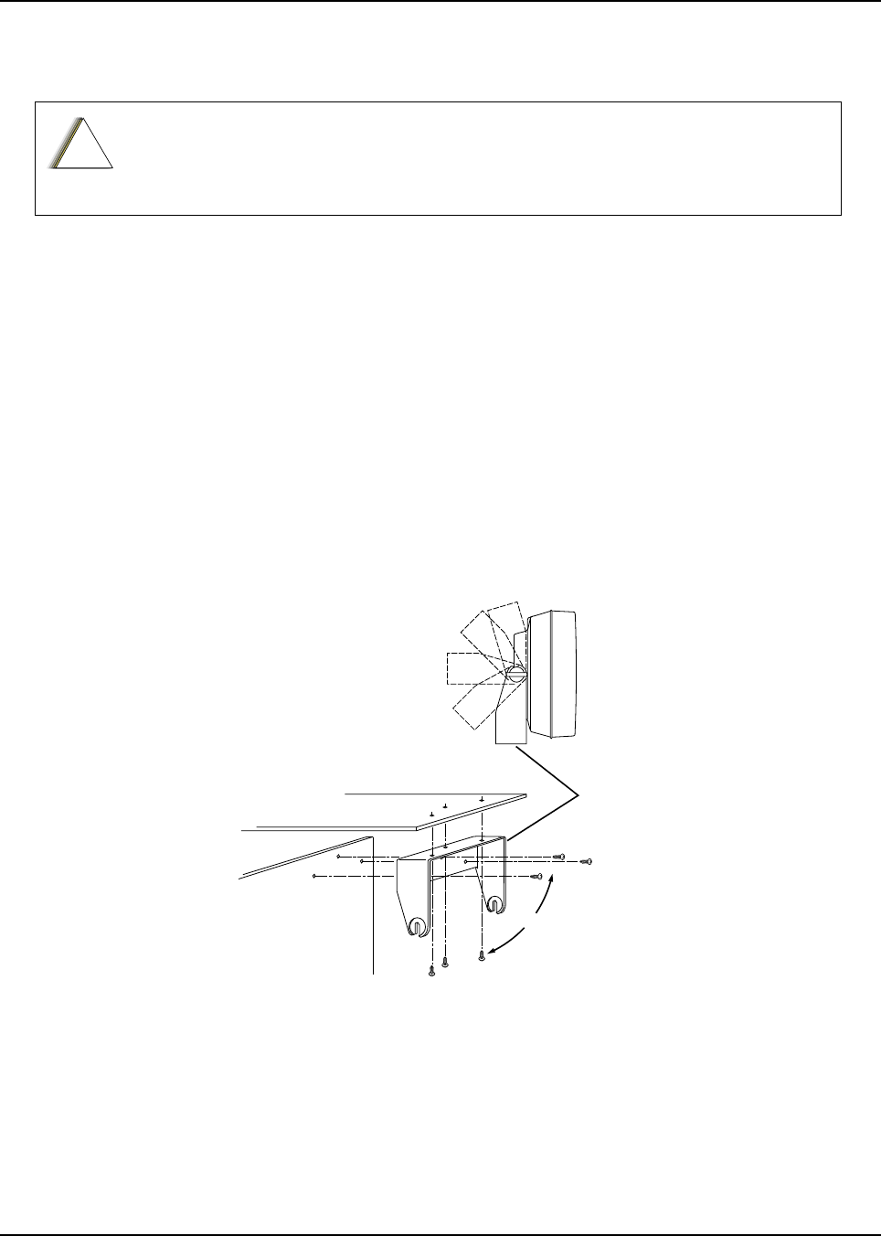
6878215A01
Standard Configurations Speaker 2-43
2.5 Speaker
The speaker kit includes a trunnion bracket that allows the speaker to be mounted in a variety of
ways. With the trunnion bracket, the speaker can mount permanently on the mounting surface or in
accessible firewall areas. The trunnion allows the speaker to tilt for best operation. Mount the
speaker out of the way so that it will not be kicked or knocked around by the vehicle occupants.
Mount the speaker as follows:
1. Use the speaker mounting bracket as a template to mark the mounting hole locations.
2. Use the self-drilling screws provided to fasten the trunnion.
3. Attach the speaker and fasten to the trunnion with two wing screws.
4. Route the speaker wires under the carpet or floor covering, or behind the kick panels. Be sure
the wires are out of the way and will not be snagged and broken by the occupants of the
vehicle.
5. Do not submerse the 2-pin speaker connector in water nor place this connector in an area
that could have standing water.
Figure 2-56. Speaker Mounting
DO NOT ground the radio's speaker leads. This system has a floating speaker output
(DC voltage on both leads); damage to the audio circuit will result if either lead is
grounded or if they are shorted together.
!
C a u t i o n
Dashboard
Firewall
Trunnion
Bracket
OR
MAEPF-25764-O
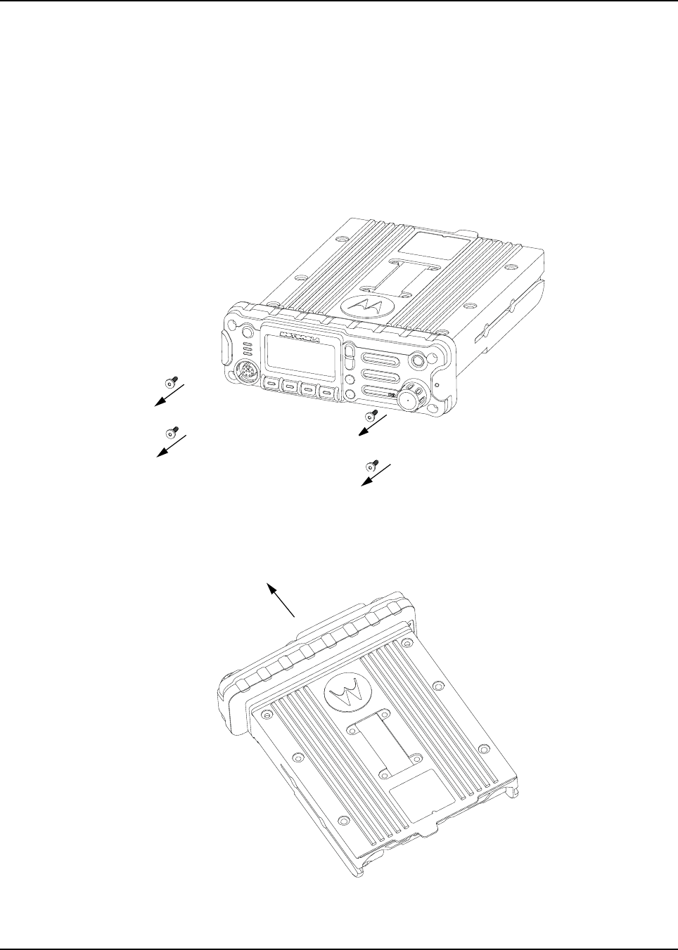
6878215A01
2-44 Standard Configurations Speaker
2.5.1 Internal Speaker Disassembly
NOTE: This configuration is only applicable for O2 Control Heads.
You can disable the internal speaker of your radio by following the instructions below.
Use the following procedure to disassemble your radio:
1. Unplug power, antenna, microphone and all accessories connections. If the radio is a
remote-mount radio, disconnect the remote-mount control cable from the front of the
transceiver.
2. Remove the four screws found on the control head with a Torx T-20 bit as shown in
Figure 2-57. Discard the screws.
Figure 2-57. Removing the screws on the Control Head
3. Firmly grasp the front panel of the control head. Carefully remove the front housing assembly
from the back housing assembly as shown in Figure 2-58. Note the position of the attached
flex and do not pull on it excessively.
Figure 2-58. Removing the Control Head

6878215A01
Standard Configurations Speaker 2-45
4. Put the control head face down on a clean, flat surface to avoid damaging it. Do not touch the
o-ring on the back housing.
5. Carefully disconnect the speaker connector from the circuit board as shown in Figure 2-59.
Figure 2-59. Disconnecting the Speaker Connector
6. Reattach the front housing assembly to the back housing assembly as shown in Figure 2-60.
Make sure that the flex is returned to its original position and that the o-ring on the back
housing assembly is not pinched.
Figure 2-60. Reattaching the Control Head
7. Secure the front housing assembly back to the back housing assembly with four new screws
using the Torx T-20 bit as shown in Figure 2-60. Apply 9 in. lbs. torque for each screw.
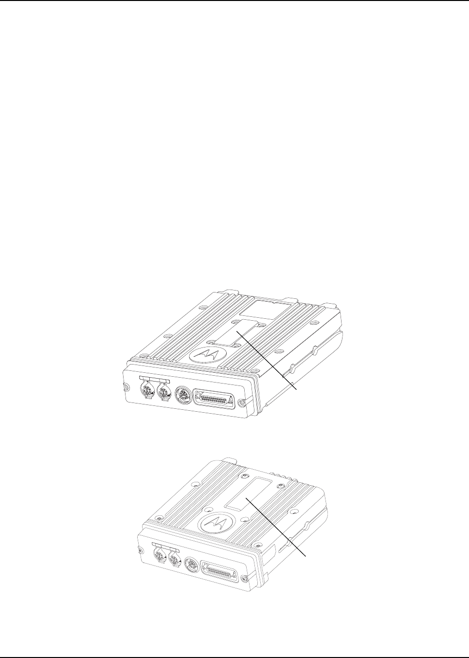
6878215A01
2-46 Standard Configurations Microphone Hang-Up Clip
2.6 Microphone Hang-Up Clip
2.6.1 Standard or O3 Control Head Hang-Up Clip
The hang-up clip must be within reach of the operator(s) and close enough to the control head to
prevent cable strain. Measure this distance before actually mounting the bracket. Since the bracket
has a positive-detent action, the microphone can be mounted in any position.
Use the hang-up clip as a template to locate the mounting holes. To avoid interference when
removing the microphone, install the flathead screw in the top clip hole.
Some microphone models require the grounding of the microphone clip in order for HUB operation to
work correctly. Refer to the documentation that comes with your Motorola microphone model.
NOTE: For multi-control head configuration where only one of the control heads has a microphone,
the control heads without a microphone attached must have their HUB or Monitor pin
(J100-22) jumpered by a wire to GND (J100-1 or J100-14) for HUB operation to work.
2.7 RFID (Option)
An APX mobile radio equipped with an RFID tag allows an alternate option for tracking the radio
asset. Each RFID equipped radio has an RFID tag preprogrammed with the individual radio’s serial
number (also found on the FCC label) as well as band and radio model information (see below for
further info).
Figure 2-61. RFID Location on Mid Power Radio
Figure 2-62. RFID Location on APX 2500/APX 4500 Mid Power Radio
RFID Tag
RFID Tag
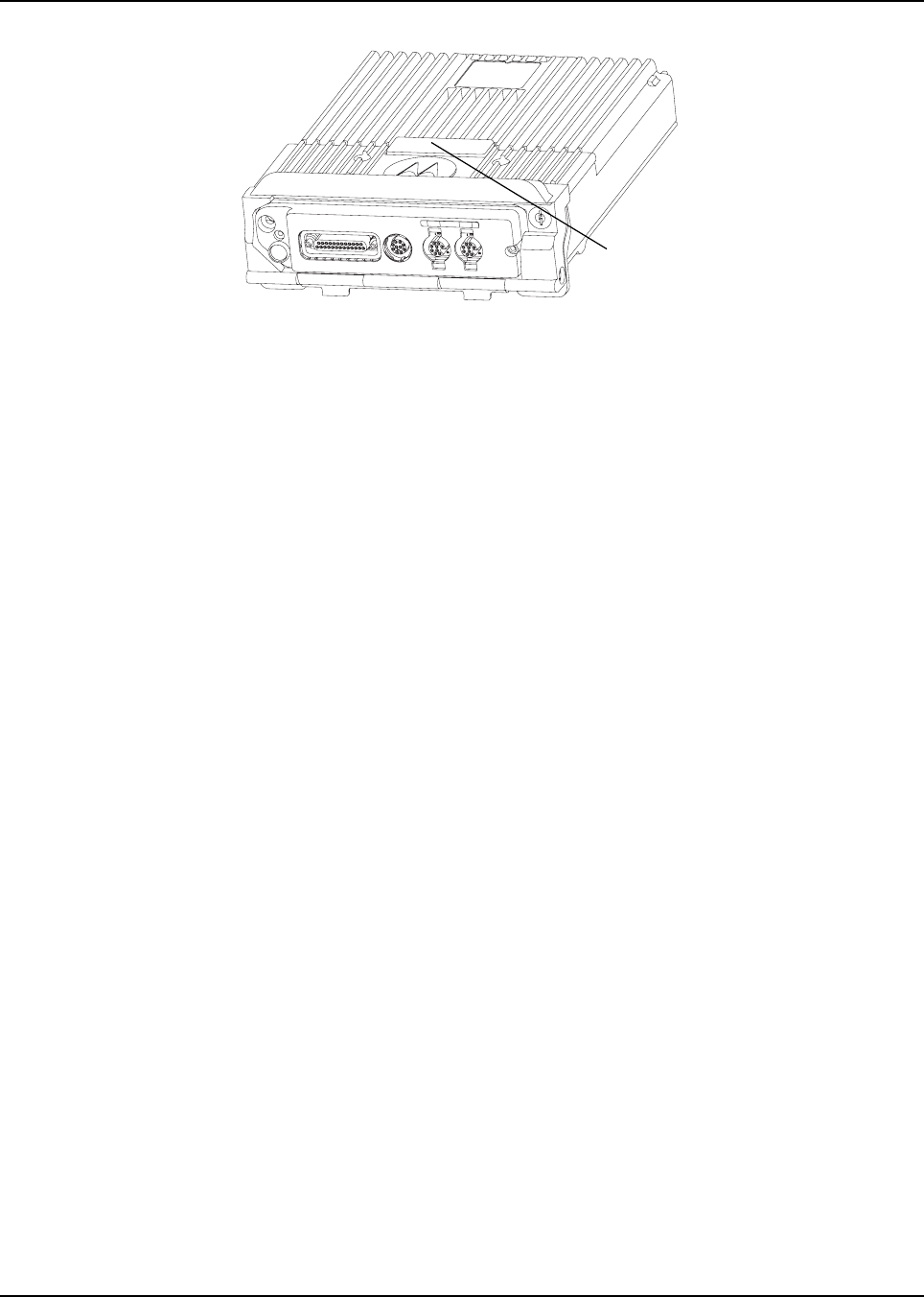
6878215A01
Standard Configurations RFID (Option) 2-47
Figure 2-63. RFID Location on High Power Radio
RFID Tag
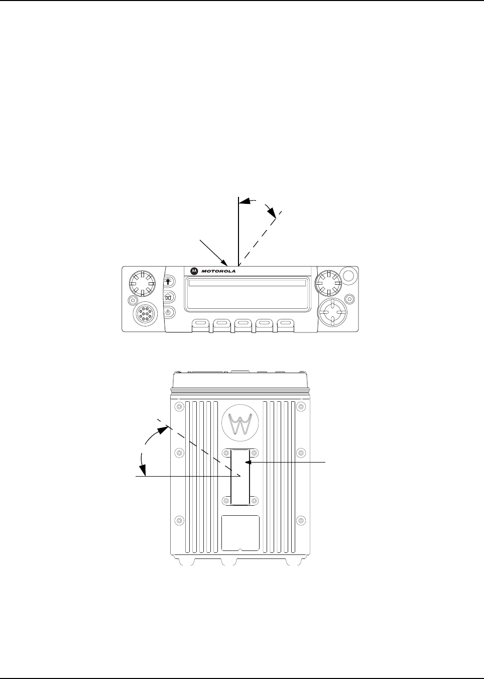
6878215A01
2-48 Standard Configurations RFID (Option)
2.7.1 RFID Reading
To read an RFID tag using a UHF Gen 2 RFID reader (e.g. Motorola’s MC9090-G), open an
appropriate RFID read application, point the RFID reader at the tag and activate the reader's RFID
antenna (e.g. pull Motorola’s MC9090-G scanning trigger). RFID reader must be within 1 foot from
tag in order to read.
Two variables, Read Angle and Reader Orientation, aid in the distance needed to read and write to
the RFID Tag. Read distance is independent of Tag Angle, but the reader should be as close to
perpendicular to the tag as possible (Read Angle).
As Read Angle increases past 60 degrees, read distance will begin to decrease; tag will become
unreadable once Read Angle exceeds 90 degrees (see Figure 2-64 and Figure 2-66). RFID tag
cannot be read through metal. The orientation of the reader (Reader Orientation) and the tag must
be aligned to improve read and writability (see Figure 2-70).
Figure 2-64. Read Angle for Mid Power Radio
Figure 2-65. Tag Angle for Mid Power Radio
O5
Read Angle
RFID Tag
RFID Tag
Tag Angle
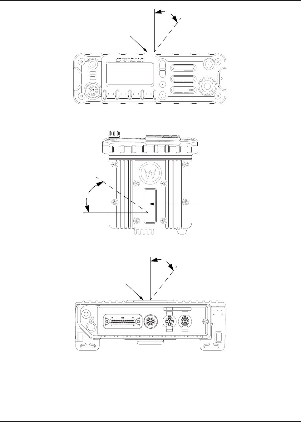
6878215A01
Standard Configurations RFID (Option) 2-49
Figure 2-66. Read Angle for APX 2500/APX 4500 Mid Power Radio
Figure 2-67. Tag Angle for APX 2500/APX 4500 Mid Power Radio
Figure 2-68. Read Angle for High Power Radio
NOTE: APX high power mobile radio is shown without handle to allow visibility of RFID tag.
Read Angle
RFID Tag
RFID Tag
Tag Angle
Read Angle
RFID Tag
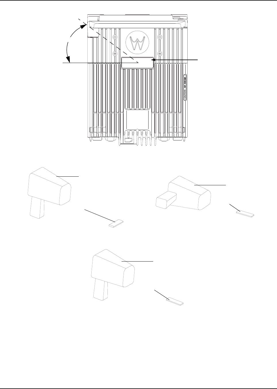
6878215A01
2-50 Standard Configurations RFID (Option)
Figure 2-69. Tag Angle for High Power Radio
Figure 2-70. Examples of Reader and Tag Aligned (Reader Orientation)
Figure 2-71. Example of Reader and Tag Misaligned (Reader Orientation)
RFID Tag
Tag Angle
Reader
Tag
Reader
Tag
Reader
Tag

6878215A01
Standard Configurations RFID (Option) 2-51
2.7.2 Programming RFID (If Equipped)
The user can reprogram the tag (up to 12 ASCII characters when encoded to hexadecimal format)
using any UHF Gen 2 capable RFID writer (e.g. Motorola’s MC9090-G).
NOTE: Follow read direction in Section 2.7.1 to optimized reprogramming.
Table 2-10. Model Number Chart in 12-Digit ASCII Format
Model Number Radio Tier/Band/Output Level Last Two Digits
M30KSS9PW1AN APX Mobile SB-MP VHF D2
M24KSS9PW1AN
APX Low Tier Mobile-MP VHF D8
M22KSS9PW1AN
M30KTS9PW1AN APX Mobile SB-HP VHF D3
M30QSS9PW1AN APX Mobile SB-MP UHF1 E2
M30QTS9PW1AN APX Mobile SB-HP UHF1 E3
M30SSS9PW1AN APX Mobile SB-MP UHF2 D2
M20TSS9PW1AN APX Mobile DB-MP 7/800-MP VHF R2
M30TXS9PW1AN APX Mobile DB-MP 7/800-HP VHF R3
M30URS0PW1AN APX Mobile SB-MP 7/800 F2
M22URS9PW1AN
APX Low Tier Mobile-MP 7/800 F8
M24URS9PW1AN
Table 2-11. Serial Number with Radio Band/Tier/Power
Characters Radio Band/Tier/Power
F7/800
DVHF
E UHF
R 7/800 and VHF
T VHF and UHF
E UHF1 and UHF2
S 7/800 and UHF
1 APX7000
2 APX7500 Mid Power
3 APX7500 High Power
4 APX6000
5 APX6500 Mid Power

6878215A01
2-52 Standard Configurations Completing the Installation
2.8 Completing the Installation
Complete the installation by connecting the speaker to the accessory cable; verify the ignition sense
wire is attached according to planned ignition sense; attach the accessory cable into J600; verify the
control head is attached to either the TIB or the CAN extension cable; and then attach the power
cable to the back of the transceiver.
6 APX6500 HighPower
7 APX Low Tier Portable
8 APX Low Tier Mobile MP
9 APX Low Tier Mobile HP
Table 2-11. Serial Number with Radio Band/Tier/Power
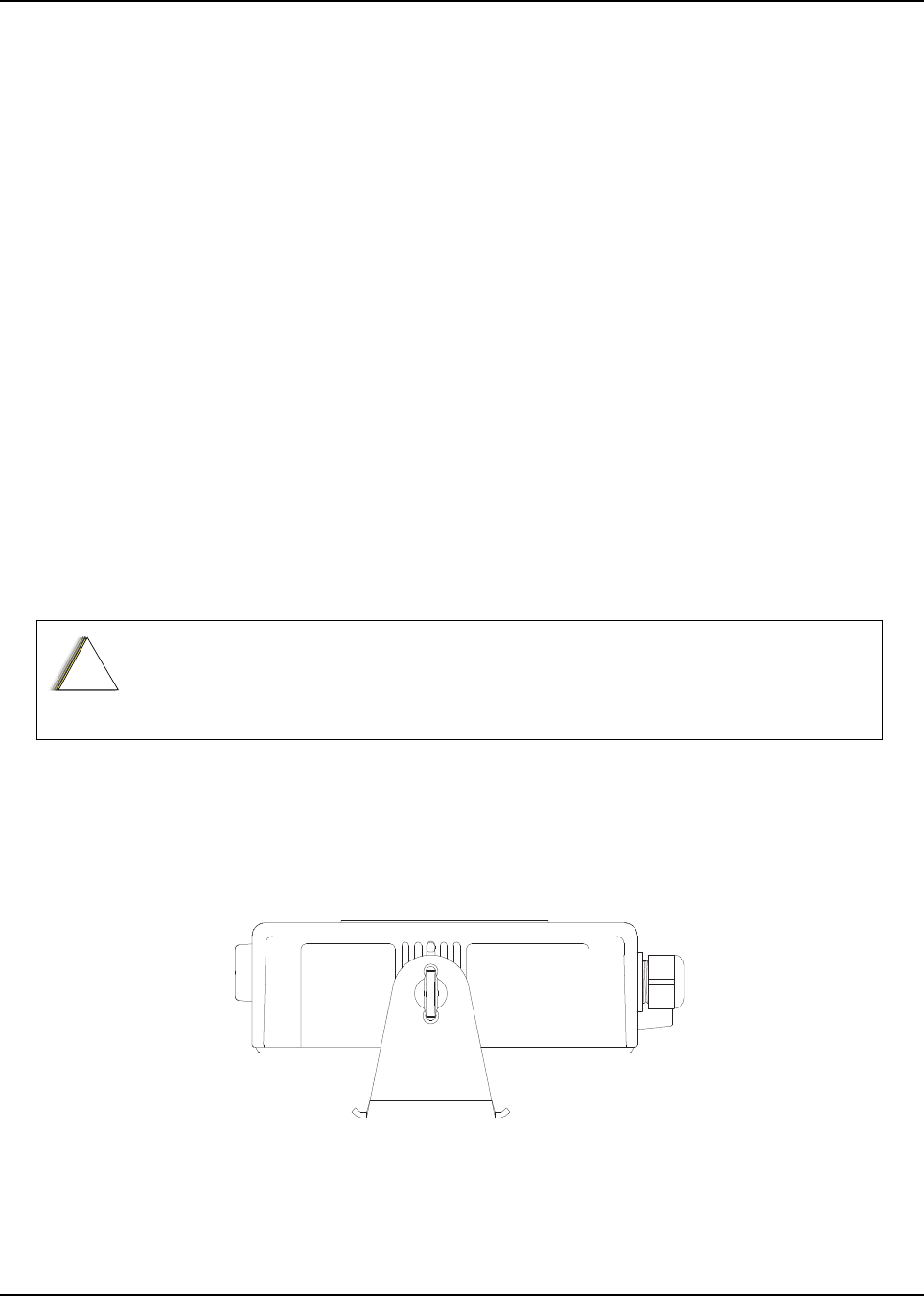
Chapter 3 Universal Relay Controller Installation
The Universal Relay Controller (URC) is an extension of and an orderable accessory for O7 or O9
control head. URC is used to control high power switching peripherals, e.g. lightbar. URC works on
all lightbars which can be controlled by power application. URC is connected to the transceiver's
GCAI port.
The URC design consists of a microcontroller and uses 10 relays to control the switching device. A
separate ground for isolation exists between the relay and MCU sections, which is provided by the
use of iCoupler from Analog Devices. Each relay is connected to an output with 15 A fuse. The
maximum load allowed on each output is 12 A. Two cables, each with the maximum of 60 A, can be
used to connect to the input connector at the bus bar. Each cable is connected with a 60 A circuit
breaker. One-wire EEPROM is employed to enable GCAI to recognize the URC accessory ID. CPS
can be used to program the relay patterns.
When installing URC, make sure to plan the installation carefully and leave additional room in the
front and rear of the box for cabling and accessory connections; and also to the sides of the radio so
that you may access and install the trunnion screws.
The recommended mounting location for URC is in the car trunk, either next to the transceiver or
within the area not further than 4.5 m away from the transceiver. Ensure that sufficient cooling is
provided. Do not cover URC with baggage, blankets, etc.
3.1 Universal Relay Controller Mounting
The mounting location must be accessible and visible. Select a location that permits routing the
cable as directly as possible.
NOTE: For optimum URC performance, orient the mounting trunnion as shown in Figure 3-1.
Figure 3-1. Universal Relay Controller Orientation
An adjustable trunnion, which allows a number of mounting positions, is supplied for mounting the
URC. The installation must not interfere with the operation of the vehicle or its accessories.
Do not backfeed power into URC.
!
C a u t i o n
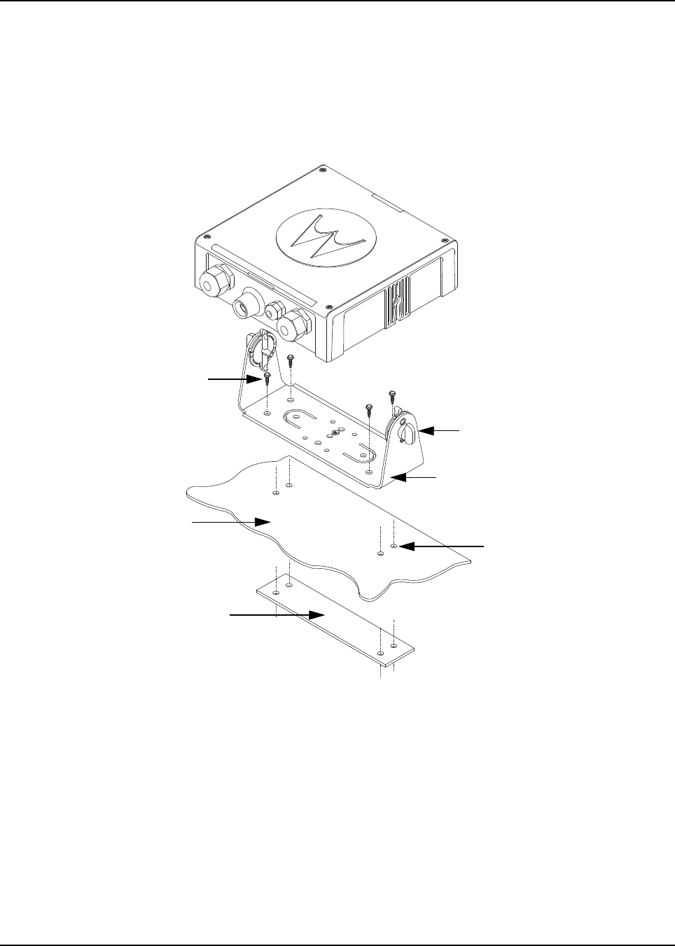
6878215A01
3-2 Universal Relay Controller Installation Universal Relay Controller Mounting
Install the URC as follows:
1. Use the URC trunnion as a template to mark the mounting holes;
drill 5/32" holes. If mounting on a plastic surface, use a metal backing plate.
2. Attach the trunnion bracket using all four 10 – 16" x 5/8" self-tapping screws provided.
3. Temporarily install the URC (adjust for proper viewing angle) and fasten it to the trunnion with
two wing screws. Test the installation to ensure that the unit is securely locked in place.
Figure 3-2. Universal Relay Controller Installation Exploded View
ADJUST THE UNIVERSAL RELAY
CONTROLLER TO DESIRED
ANGLE AND SECURE WITH WING
SCREWS
USE FOUR MOUNTING SCREWS
ON ALL INSTALLATIONS
TRUNNION
DRILL FOUR 5/32'' HOLES
IN MOUNTING SURFACE
MOUNTING SURFACE
IMPORTANT
USE A METAL BACKING PLATE
(NOT SUPPLIED) IF MOUNTING
TRUNNION ON PLASTIC OR
UNSTABLE SURFACE
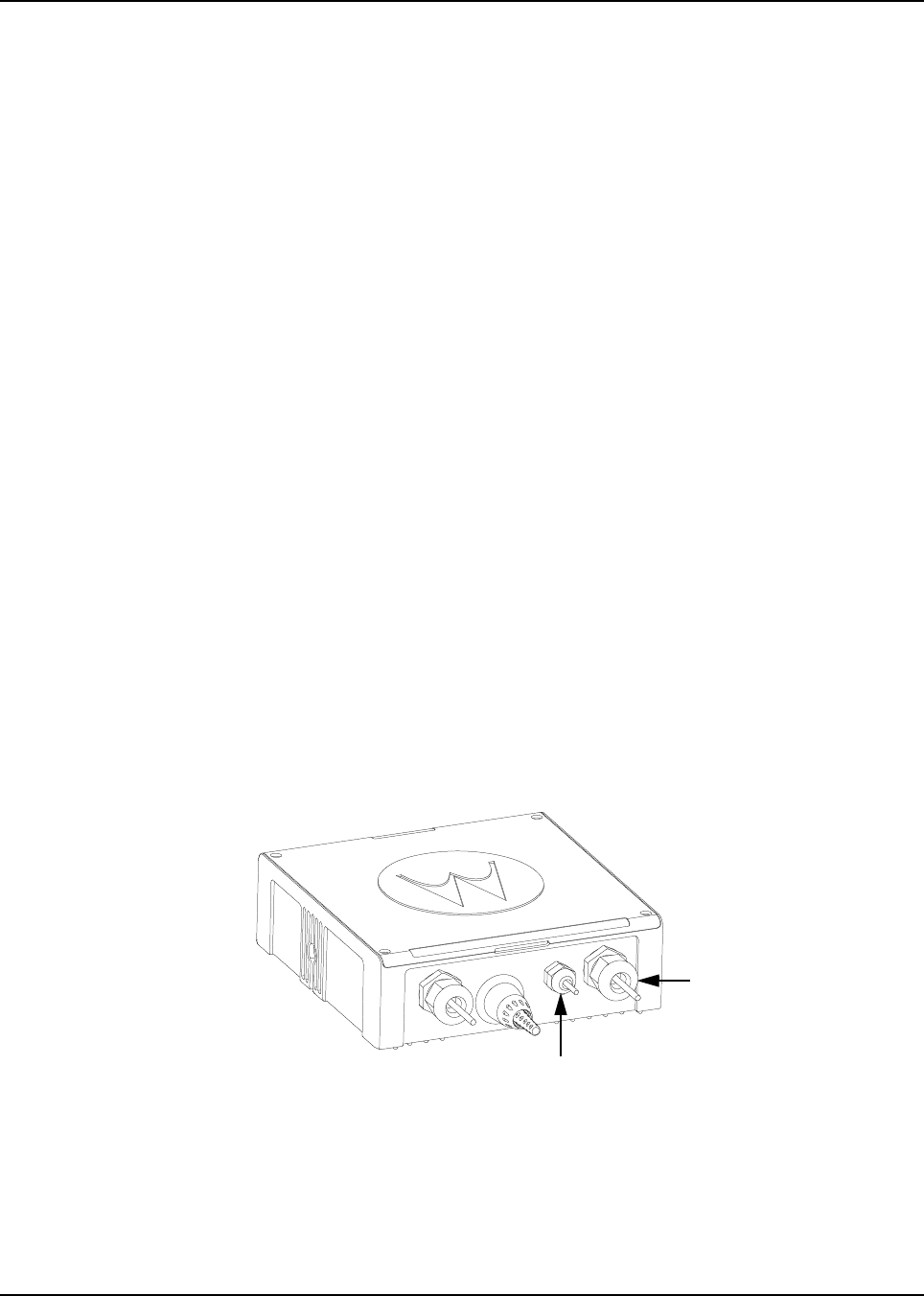
6878215A01
Universal Relay Controller Installation O7/O9 Universal Relay Controller Cable Assembly 3-3
3.2 O7/O9 Universal Relay Controller Cable Assembly
3.2.1 Power Cable
1. Remove the cap nut of power cable gland assembly, and insert the power cable through the
cap nut and neoprene seal in the cable gland body. Use power cable with either AWG 6 or
AWG 8 only (recommended OD range of cable is 5.5 mm to 9 mm) that is able to withstand
80 A and 50 A respectively, to ensure water sealing of the controller. User can decide to
install one or two power cables based on the requirements. The power cables (A+) are not
supplied.
2. The loose end of the power cable with cable strip length 7.94 mm (5/16”) is then placed on
the power lug and secured down by a set screw. The cap nut is then reassembled with
tightening torque 18 lb-in.
3. The other end of the power cable should be connected to circuit breaker (Motorola part
number 40012006001) end which indicates "AUX" and then, to power supply on the other
end which indicates "BAT", instead of connecting to power supply directly.
4. Repeat steps 1 to 3 to install the second power cable, if required.
5. If only one power cable is installed, it is recommended to cover the other side of the power
cable gland with power cable gland seal with tightening torque 18 lb-in.
3.2.2 Ground Cable
1. Remove the cap nut of ground cable gland assembly, insert the ground cable through the cap
nut and then reassemble the cap nut. Use ground cable with AWG 14 only (recommended
OD range of cable is 2 mm to 4 mm) that is able to withstand 5 A. The ground cables (A+) are
not supplied.
NOTE: The ground is used to switch the relays, and not act as a ground to the actual device being
controlled.
2. The loose end of the ground cable with cable strip length 7.94 mm (5/16”) is then connected
to a two-pin terminal block. Both pins on the terminal block are inter-connected and either pin
can be used. The cap nut is then reassembled with tightening torque 7 lb-in.
Figure 3-3. Power and Ground Cable Glands
Ground Cable Gland
Power Cable Gland
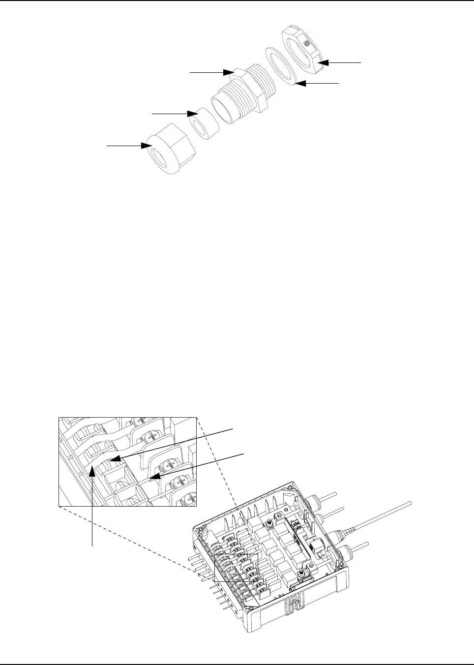
6878215A01
3-4 Universal Relay Controller Installation O7/O9 Universal Relay Controller Cable Assembly
Figure 3-4. Cable Gland Assembly with Gasket
3.2.3 Wires
1. Assemble the wires into the lightbar gasket retainer and lightbar gasket. The URC can
support lightbars through control wires with outer diameter ranging from
1.52 mm to 3.77 mm (0.06” to 0.148”), with wire gages ranging from AWG 12 – 20.
2. Each individual loose wire (prior to stripping off the wire jacket) needs to be inserted one at a
time through the chassis. Ensure the lightbar wire is straight before inserting the wire into the
chassis. Each wire is sealed individually by the radial gasket seal. When a thick wire (i.e.
AWG 14 wire or wire OD > 2.90 mm) is inserted through the chassis, there is potential torn at
the rubber gasket. Remove the rubber gasket residual and continue to the next step.
3. Thin wires 2.5 mm and below should be dressed into the retention feature using a black stick
(see Figure 3-5); thick wires above 2.5 mm should be routed above the retention feature.
Strip off the wire until 7.94 mm (5/16”) after the wire is inserted into the URC, and install the
wire into respective lightbar terminal block.
4. Cover the lightbar gasket retainer's hole with seal, gasket and ground cable gland, if no wire
is inserted.
Figure 3-5. Wires Installation
Counter Nut
Gasket, Cable Gland
Neoprene Seal
Cap Nut
Cable Gland Body
WIRE RETENTION FEATURE
LIGHTBAR WIRE WITH DIAMETER
2.5 mm AND BELOW
LIGHTBAR WIRE
WITH DIAMETER
ABOVE 2.5 mm
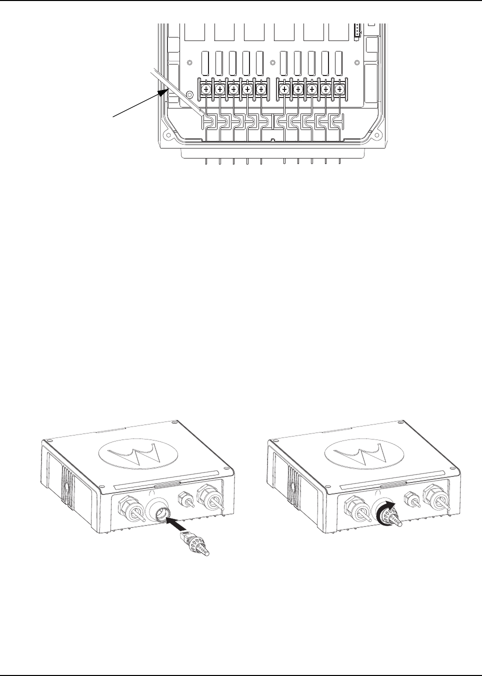
6878215A01
Universal Relay Controller Installation O7/O9 Universal Relay Controller Cable Assembly 3-5
Figure 3-6. Wire Installation with Black Stick
5. The lightbar gasket should be replaced at each reassembly of the wire.
NOTE: Use of other cable gages except as recommended in this manual may result in water
intrusion. Any reassembly of wire needs a new lightbar gasket replaced. If the current loading
for one wire is higher than 12 A, the wires should be splitted before being assembled to the
URC system. Wires kit (PMKN4109_) is provided to ease installation of the URC. Incorrect
use of the wires kit, e.g. improper connection at external loose end wires, may impact the
robustness of the URC.
Remove the wires and gasket residual inside the URC after the wire installation, before
closing the top housing of the URC.
3.2.4 O7/O9 to URC Cable
The O7/O9 to URC cable (Motorola part number 3064153H02) can be assembled either before or
after reassembling the top housing. Assemble the RJ45 port of the cable into the RJ45 connector on
the URC and turn the locking collar instead of cable, 90 degrees to the right to ensure it is locked
properly. After that, test whether the cable is locked properly or not by trying to pull out the cable.
Figure 3-7. O7/O9 to URC Cable Installation
Black Stick

6878215A01
Notes
3-6 Universal Relay Controller Installation
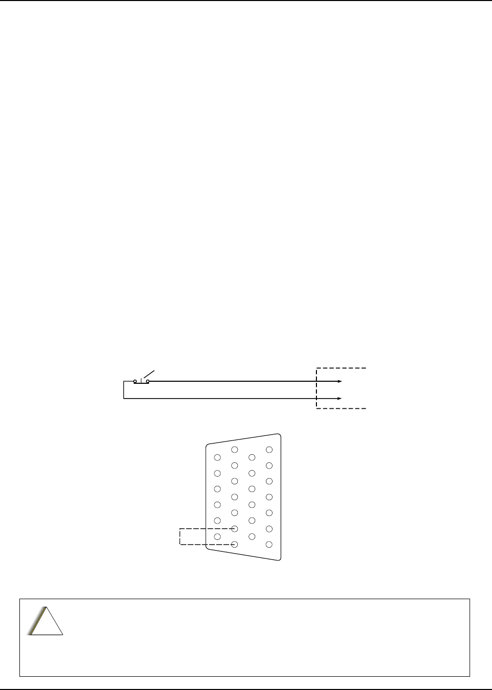
Chapter 4 Options and Accessories Installation
4.1 Dash-Mount Accessory Installation
NOTE: This configuration is not applicable for 100W radios.
For dash-mounted configurations, the accessories must be installed through the accessory
connector assembly that is located on the rear of the radio, adjacent to the power connector.
Motorola-approved accessories are supplied with male terminals crimped to a 20-gauge wire
specifically designed to fit the plug of the accessory connector assembly.
Insert the male terminal into the accessory connector assembly in the appropriate location and
connect the accessory connector assembly in the rear accessory port. Do not use other generic
terminals in the plug. Generic terminals can cause electrical intermittencies and may cause damage
to the plug.
4.1.1 Dash-Mount Emergency Pushbutton or Footswitch Installation
Mount the footswitch using the hardware that comes with the kit. Open the accessory cable
connector housing; remove the jumper wire. Connect the emergency switch wires to pins 14 and 15
(see Figure 4-1). Close the connector housing; route the finished cable from the switch location to
the control head location.
NOTE: The emergency footswitch should be attached with A+ unattached.
A+ should be attached after successfully securing the screws in the connector.
Figure 4-1. Emergency Switch Wiring Diagram
The radio is sold with correct accessory cables and jumpers in order to have emergency
de-activated by default, regardless of the setting in CPS. However, if cables are not used, or if
jumpers are removed without replacing with an emergency accessory button/switch at one of
the accessory ports, the radio will power-up upon the application of A+. The display may not
show an indication that the radio is on, and this can result in an incorrect operation of the radio
as well as excessive current drain of the vehicle’s battery when the engine is off.
ACCESSORIES
CONNECTOR
J2 IN DASH MOUNT
J100 IN REMOTE MOUNT
PIN 14
PIN 15
NOTE 1
SPST NORMALLY CLOSED
EMERGENCY SWITCH
NOTE 1: REMOVE BLACK JUMPER WIRE INSIDE
ACCESSORY CONNECTOR HOUSING.
INSERT WIRES FROM EMERGENCY SWITCH
GND
EMER
1
7
8
14
13
20
21
26
!
C a u t i o n
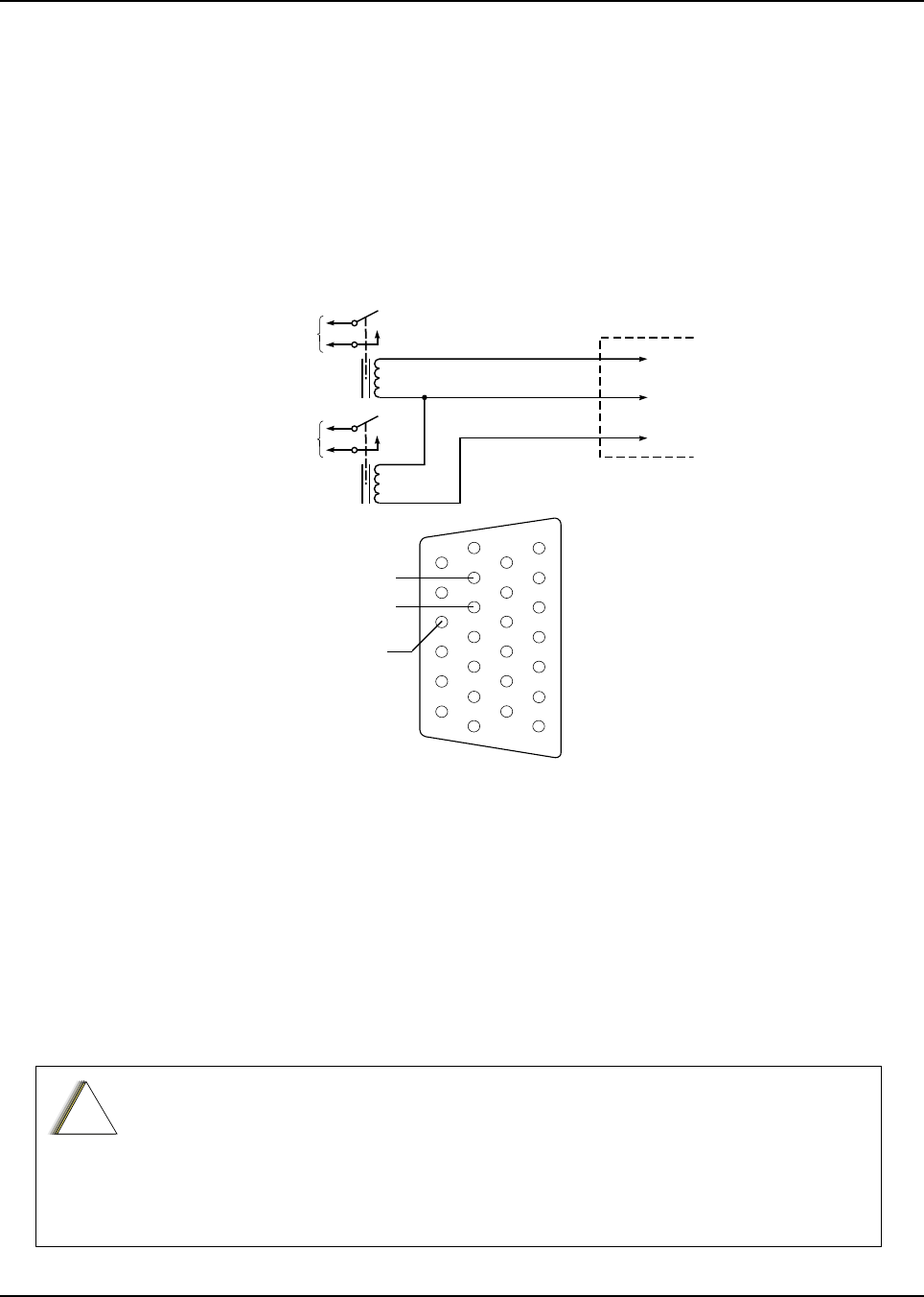
6878215A01
4-2 Options and Accessories Installation Remote-Mount Accessory Installation
4.1.2 Dash-Mount Horn and Lights (External Alarms) Relays
NOTE: For installations that use the horn/lights option, select a suitable location for mounting
(normally under the dash) and, referring to Figure 4-2, perform the following procedure:
1. Horn Relay – Connect the relay contacts across the horn ring switch, typically found in the
steering column. Open the accessory cable connector and connect the two control wires
(male pins) into locations 18 and 24 of the connector.
2. Lights Relay – Connect the relay across the head lamp ON/OFF switch, typically found in
the steering column. Open the accessory cable connector and connect the two control wires
(male pins) into locations 19 and 24 of the accessory connector.
Figure 4-2. Horn/Light Wiring Diagram
4.2 Remote-Mount Accessory Installation
Perform the following installation procedure:
1. Select an appropriate place to mount the option or accessory hardware.
2. Route the accessory-to-control head cables under floor coverings or behind panels so that
the vehicle occupants do not snag or break the wires.
3. Attach wires from the accessory to the appropriate wire on the VIP cable (see Table 4-1 and
Table 4-2).
The radio is sold with correct accessory cables and jumpers in order to have
emergency de-activated by default, regardless of the setting in CPS. However, if
cables are not used, or if jumpers are removed without replacing with an emergency
accessory button/switch at one of the accessory ports, the radio will power-up upon
the application of A+. The display may not show an indication that the radio is on, and
this can result in an incorrect operation of the radio as well as excessive current drain
of the vehicle’s battery when the engine is off.
CONNECT
A
CROSS HORN
RING SWITCH
CONNECT
ACROSS HEAD
LAMP SWITCH
SPST
N.O.
RELAY
12V COIL
12V COIL
VIP OUT 1
SWB+
VIP OUT 2
SPST
N.O.
RELAY
ACCESSORIES
CONNECTOR
PIN 18
PIN 24
PIN 19
SWB+
VIP OUT 2
(LIGHTS)
VIP OUT 1
(HORN)
1
7
8
14
13
20
21
26
!
C a u t i o n
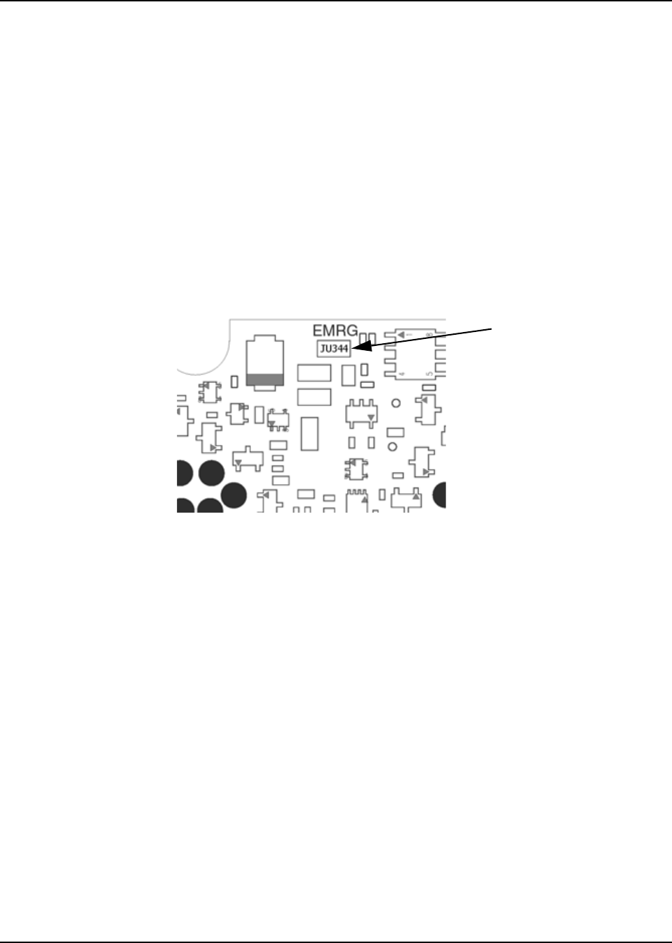
6878215A01
Options and Accessories Installation Remote-Mount Accessory Installation 4-3
4.2.1 Emergency Pushbutton or Footswitch Installation
Mount the switch using the hardware that comes with the kit. Connect the button/switch wires to a
ground pin and the emergency pin, removing the default jumper wire in the rear accessory cable.
The button/switch will short the pins when in-active. When the button/switch is pressed, its contact
opens, the emergency path is un-ungrounded and pulled-high inside the radio transceiver, and
detected by the processor. If an emergency accessory is used at either (or both) J2 connector and
J626 connector, all jumper wires, shorting emergency to ground, must be removed so button/switch
press can be detected.
In additional to removing the default jumper wires in accessory cables, you must also remove a
jumper part on the printed circuit board of the TIB, in order for the button/switch to be detected. On
the TIB PCB (both mid power and high power use the same TIB) a zero-ohm jumper is placed by
default so that the radio does not go into emergency when no cable is attached at either J2 or J626
in remote mount configuration. This jumper part, JU344, must be removed if either or both J2 and
J626 will have any type of emergency cable and button/switch attached. Otherwise, the processor
will never see emergency become un-grounded.
Figure 4-3. Emergency Jumper Removal in Remote Mount
1. Turn-off power to the radio system.
2. Detach the TIB from the radio transceiver.
3. Detach the TIB flex.
4. Remove TIB PCB from the plastic housing using TORX T10 screwdriver. Refer to the
disassembly procedure in the Basic Service Manual.
5. Located JU344, See diagram
6. Remove JU344 from the TIB PCB using a soldering gun. Clean off excess solder.
7. Reassemble the TIB following the Basic Service Manual procedure. Use 6-8 in-lbs torque
on each screw. Remember to include the TIB O-ring gasket.
8. Re-attach the TIB flex.
9. Re-attach the TIB to the radio transceiver.
10. Apply 6-8 in-lbs of torque to each screw to secure the TIB to the radio transceiver.
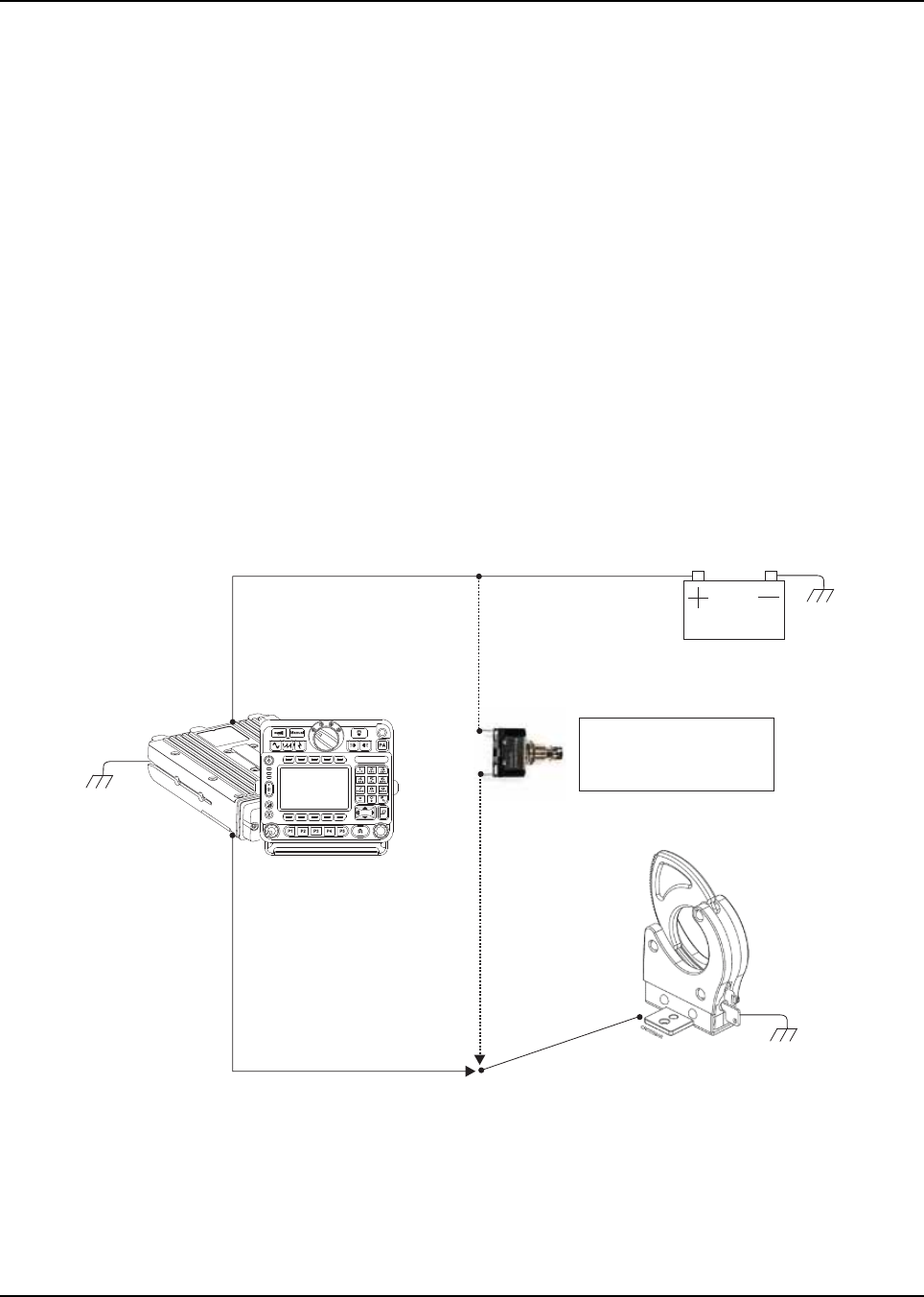
6878215A01
4-4 Options and Accessories Installation Remote-Mount Accessory Installation
4.2.2 Horn (External Alarm) Relay Installation
Mount the horn relay in a suitable location (normally under the dash). Connect the relay contacts
across the horn ring switch, typically found in the steering column. Connect the two control wires to a
SW B+ pin and a VIP OUT pin on the VIP connector.
4.2.3 Lights (External Alarm) Relay Installation
Mount the light relay in a suitable location (normally under the dash). Connect the relay contacts
across the head lamp ON/OFF switch. Connect the two control wires to a SW B+ pin and a VIP OUT
pin on the VIP connector.
4.2.4 Gunlock Installation
The O7 or O9 control head can program up to three gunlocks through the programmable buttons.
You can set the time for the momentary trigger using the time-out trigger button. Connect the relay
contacts across the gunlock switch to install the gunlock. Connect the two control wires to a SW B+
pin and a VIP OUT pin on the VIP connector.
It is recommended to install a failsafe/redundant bypass switch for the gunlock. It is suggested to use
a separate timer switch or a manual push-on button switch to activate the gunlock. Connect the
switch from the supply to the gunlock directly, as shown in Figure 4-4. Place the manual button at a
suitable and reachable location, yet not easily seen.
Figure 4-4. Gunlock Switch Redundancy Diagram
Transceiver
and
control head
VIP Cable
VIP OUT
GND
GND
GND
Gunlock
Redundancy
Wiring
Car Battery
Momentary or
time-out bypass
manual switch
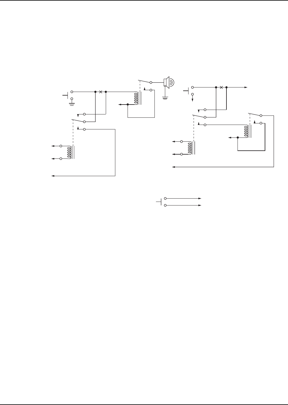
6878215A01
Options and Accessories Installation Remote-Mount Accessory Installation 4-5
4.2.5 Horn-Ring Transfer
Configure the Horn Relay for either Negative Contact or Positive Contact as shown in section 6.3 of
the siren/PA manual (6881093C18). Program the designated VIP-OUT line for “Horn-Ring Transfer”
and program the designated VIP-IN line for “Horn-Ring”.
Figure 4-5 shows wiring diagrams for connecting the Horn-Ring via a transfer relay for both negative
and positive ground systems. Refer to the siren/PA manual (6881093C18) for more information.
Figure 4-5. Siren/PA Horn-Ring Connections
4.2.6 Record Audio Out Jack of Transmit and Receive Audio
The use of Power Cable kit HKN6187_ (see Figure 2-47) provides access to both the transmitted
audio speech, as well as the received audio speech. This can be recorded with a standard tape
recorder using a 2.5 mm connector.
4.2.7 Earphone Jack
The use of Power Cable kit HKN6187_ (see Figure 2-47) provides the ability to use a standard
earphone/headset instead of the external speaker. Once a cable is plugged into this 2.5 mm jack, the
external speaker attached at the control head will turn mute.
To Horn
Break
Here
Horn
Ring
To Control Head VIP
Output Programmed for
Horn-Ring Transfer
To Control Head VIP
Input Programmed
for Horn-Ring
To SW B+ at
VIP Connector
N.C.
COM.
N.O.
To DIG. GND at
VIP Connector
+ 12V
Positive-Contact Horn-Ring
Negative-Contact Horn-Ring
Under Hood
Horn Relay
Horn
Break
Here
Horn
Ring
To Control Head VIP
Output Programmed for
Horn-Ring Transfer
To Control Head VIP
Input Programmed
for Horn-Ring
Any SPDT Relay with 12V Coil
and Suitable Contact Ratings for
Vehicle Installation
N.C.
COM.
N.O.
+ 12V
Normally-Open
Momentary
Contact Pushbutton
To VIP Input Programmed for Horn-Ring
To DIG. GND at VIP Connector
Pushbutton Connections
NOTE: Locate Pushbutton
in a Location Convenient to
the Driver
To SW B+ at
VIP Connector
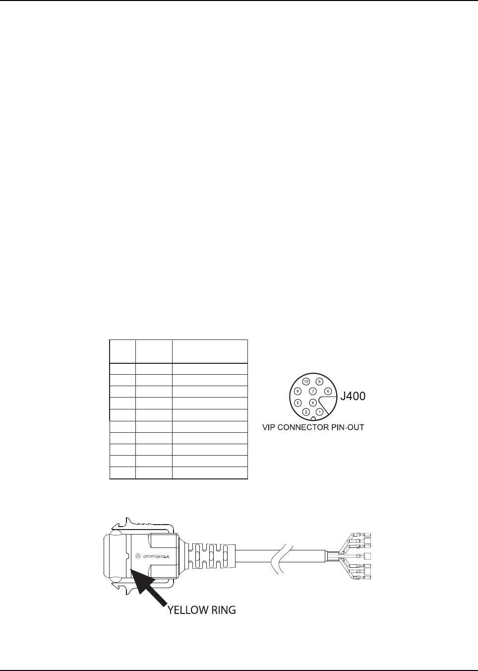
6878215A01
4-6 Options and Accessories Installation Vehicle Interface Port Overview
4.2.8 USB Data Cables
It is recommended that the USB 1.5 meter data cable HKN6163_ is used for both dash mount
configurations (at J2 connector) and for remote mount configurations (at J100 connector). This is
because the HKN6163_ has the emergency jumper present, which is necessary for correct dash
mount configurations. For interfacing at the MMP port, use Cable HKN6184_ which is a USB device
cable.
The USB 4 meter (15 feet) data cable enable HKN6172_ is recommended for remote mount
configurations only (at J100).
If the customer intends to use the HKN6172_ for dash mount configurations (at J2), the cable’s
26-pin connector must be opened and an emergency jumper-wire placed across pins 14 and 15.
Refer to Figure 4-1.
4.2.9 RS232 Cables
The following are RS232 cables. Although not compatible with CPS radio reading or programming,
they can be used for interfacing with RS232 accessories or RS232 computer programs. HKN6122_
is an RS232 serial COM port computer interface cable from J600 connector. HKN6160_ is a 6 feet
dash RS232 cable from J2 connector. HKN6161_ is a 20 feet dash RS232 cable from J2 connector.
HKN6183_ is a 4 meter cable from MMP connector.
4.3 Vehicle Interface Port Overview
The Vehicle Interface Port (VIP) allows the control head to operate outside circuits and to receive
inputs from outside the control head. There are three VIP outputs which are used for relay control.
There are also three VIP inputs which accept inputs from switches (remote mount only).
Figure 4-6. Remote Control Head Pinouts
Figure 4-7. HKN6196_ VIP Connector Detail
J400-1 RED SWB +
J400-2 GREEN GND
J400-3 - NO PIN
J400-4 - "VIP" detect: GPIO=HIGH
J400-5 BLUE VIP_OUT_1
J400-6 YELLOW VIP_OUT_2
J400-7 BLACK VIP_OUT_3
J400-8 WHITE VIP_IN_1 (VIP_IN GPIO)
J400-9 ORANGE VIP_IN_2 (VIP_IN GPIO)
J400-10 VIOLET VIP_IN_3
Radio
Pin
Number
VIP Cable
(HKN6196_)
Wire Color
Function
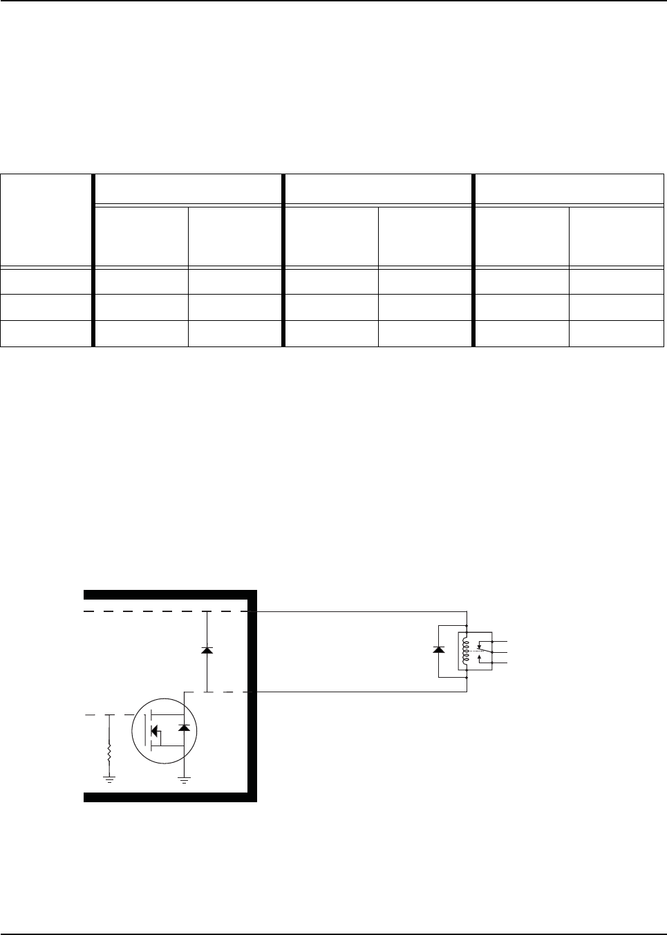
6878215A01
Options and Accessories Installation Vehicle Interface Port Overview 4-7
4.3.1 VIP Output Connections
The VIP output pins are on the back of the control head (J100 and J400), or the rear accessory port
(J2), as shown in Figure 2-10, Figure 4-12 and Figure 4-13, respectively. Use these connections to
wire control relays. One end of the relay should connect to switched B+ voltage, while the other side
connects to a software controlled ON/OFF switch inside the control head. The relay can be normally
on or normally off depending on the configuration of the VIP outputs. There are three VIP output
connections, as follows:
The function of these VIP outputs can be field programmed in the control head. Typical applications
for VIP outputs are external horn/lights alarm and horn ring transfer relay control. For further
information on VIP outputs, see the control head programming manual.
VIP OUT 1 and VIP OUT 2 can be accessed from either J100 or J400 connectors. This is to allow a
previously wired VIP OUT at J2 to move easily to J100. However, when any cable is inserted into
J400, J100 VIP OUTs are disabled.
When installing relays to the VIP OUT lines, a diode is necessary to prevent damage to the transistor
or MOSFET, due to “back EMF” when the field collapses on the relay coil. Some vendor relays
already come with this diode built-in, and other relays require the customer to install it. Figure 4-8
shows the proper placement of the diode across the relay coil. The transistor or MOSFET is located
inside the radio or the D.E.K. box.
Figure 4-8. Relay Coil
NOTE: See Appendix A: Replacement Parts Ordering to order relay’s for your VIP OUT applications.
Example relay hardware: TLN4533_ (relay without internal diode), HLN6969_ (relay with
internal back EMF protection diode), and HKN4258_ (relay wiring cable).
Table 4-1. VIP Output Connections
VIP OUT #
J400 J2 J100
SW B+ Pin
Number
On/Off
Switched Pin
Number
SW B+ Pin
Number
On/Off
Switched Pin
Number
SW B+ Pin
Number
On/Off
Switched Pin
Number
1 Red 1 5 (Blue) 24 18 24 18
2 Red 1 6 (Yellow) 24 19 24 19
3Red 17 (Black)NANANANA
N.C.
N.O.
Relay
G
D
S
VIPout
SW B+
Note:
To 'activate' a VIPOUT, you have to ground the VIPOUT, such that the
current now flows thru the relay coil to GND through a MOSFET inside
the radio or control head, which causes the relay wiper to toggle. The
MOSFET of a VIPOUT should never be used to directly drive an
accessory. The MOSFET should be used to control an external relay.
Protection
Diode
6878215A01
4-8 Options and Accessories Installation Vehicle Interface Port Overview
4.3.2 VIP Input Connections
The VIP input pins are only available on the back of the control head (remote mount). These
connections control inputs from switches. One side of the switch connects to ground while the other
side connects to a buffered input on the control head. The switch can be normally closed (NC) or
normally open (NO) depending on the configuration of the VIP inputs. There are three VIP input
connections, as follows:
NOTE: Remote Mount requires the VIP cable to be attached to J400.
MCH installations require the VIP inputs to be connected to the head assigned ID #1. See
Section 2.2.2.5: “Setting the Initial Control Head ID” on page 2-29 for further information.
Table 4-2. VIP Input Connections
VIP IN #
J400 J2
Ground Pin
Number
On/Off Switched
Pin Number
Ground Pin
Number
On/Off Switched
Pin Number
1 2 (green) 8 (white) NA NA
2 2 (green) 9 (orange) NA NA
3 2 (green) 10 (violet) NA NA
APX mobile radios equipped with the following features are capable of transmitting
automatically, even if the radio is turned off:
• Automatic Vehicle Location
• Other Special Data Products
All APX mobile have accessory connector pins 14 and 15 connected together to allow
the radio to power down. Opening this connection by REMOVING the accessory
connector, or otherwise failing to maintain a normally closed path, could, if left
unchecked, drain the vehicle battery, and possibly cause transmissions to occur.
!
C a u t i o n
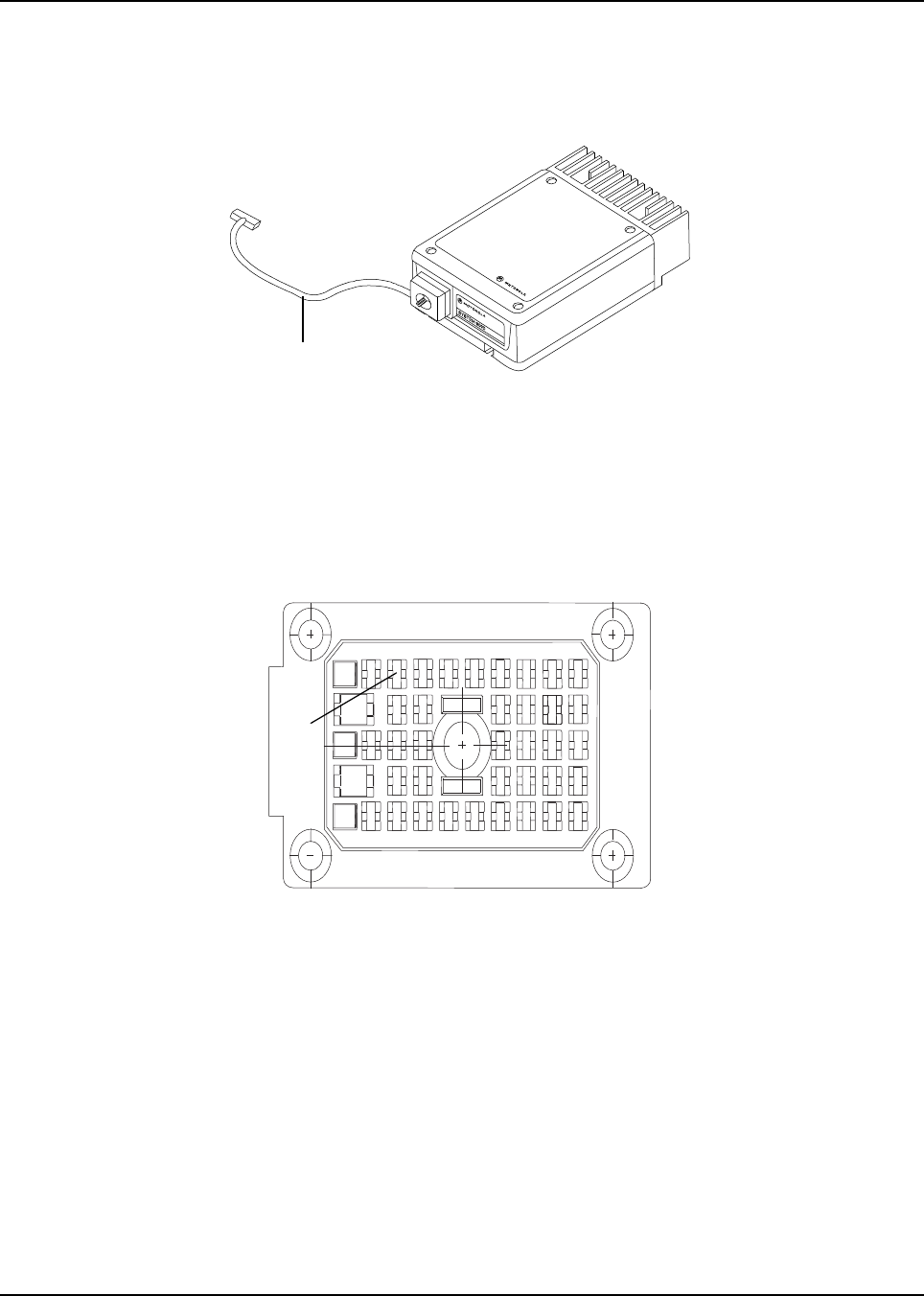
6878215A01
Options and Accessories Installation Compatibility of Emergency when Attaching a Siren 4-9
4.4 Compatibility of Emergency when Attaching a Siren
When using emergency footswitch or pushbutton with siren/PA configuration, REMOVE pin 8
(emergency) from the siren connector of the HKN4363_ siren cable as follows:
Figure 4-9. Field adjustment for Emergency Operation with Siren Accessory
1. Remove the knob from the siren/PA cable connector.
2. Remove all four screws from the connector in the siren/PA cable.
3. Open the connector cap and locate pin 8.
4. Using the contact removal tool (6684690C02), remove pin 8 from the connector.
5. Put the connector cap in place and proceed to reinstall the four screws and the knob.
Figure 4-10. Location for Pin 8
Siren Cable
1
2
3
4
5
67 8
9
A
B
2930
3132
3334
35
36
37
23
24
25
26
16
17
18
19
10
11
12
13
1415
20
21
22
27
28
Pin 8

6878215A01
4-10 Options and Accessories Installation Accessory Connector Assembly Details (P2) (All Models Except 100W)
4.5 Accessory Connector Assembly Details (P2)
(All Models Except 100W)
The APX mobile accessory connector assembly is mounted on the right rear of the radio, opposite
the antenna and adjacent to the power connector. It is fastened to the radio via jackscrews and held
together by the two cover screws. It is a multi-functional connector that allows for many different
types of adaptations. All approved accessory wires are securely strain-relieved through the exiting
slots at the back of the accessory connector assembly. The terminations that are supplied with all
accessories are designed to be fully engaged and locked into the plug connector (6680163F01).
They can also be detached for service with the assistance of a terminal removal tool. The accessory
connector assembly can be serviced multiple times for future installation upgrades.
The accessory connector assembly, supplied with every APX mobile dash-mounted radio, is
equipped with a 26-pin plug assembly, two covers, two jackscrews, two cover screws, one
emergency jumper, one ignition sense cable assembly, and one speaker pigtail. The jumper is
provided to complete the circuit for emergency mode. If this circuit becomes open, the radio will be
set to emergency mode.
39800834F03 is the crimping pin part number for use with any wires used inside the accessory cable
connector.
4.5.1 Disassembly and Assembly
4.5.1.1 Disassembly
1. Disconnect the negative terminal from the vehicle’s battery. Make sure that the battery cable
is secured such that it will not power the vehicle’s electrical system.
2. Unscrew both jackscrews completely.
3. Pull the accessory connector assembly out from the radio.
4. Loosen both cover screws, but do not remove them completely.
5. Pull the jackscrews away from the plug and hold them back.
6. Pry apart the accessory connector assembly covers.
7. Attach any new wire to its proper location by pushing in the male terminal. When you hear a
pop, the wire is engaged. To verify that the wire is engaged, tug gently on the wire and be
sure it does not come out. Do not overload the wire: severe damage will result to the plug.
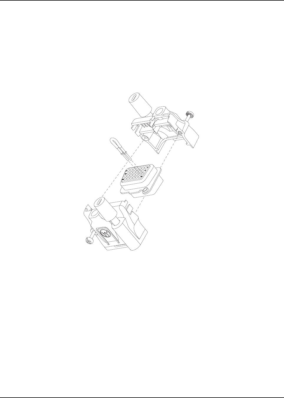
6878215A01
Options and Accessories Installation Accessory Connector Assembly Details (P2) (All Models Except 100W) 4-11
4.5.1.2 Assembly
1. Place the plug in one cover. Be sure that the flange of the plug is in the slot of the cover.
See Figure 4-11.
2. Push the jackscrew through the plug to hold it in.
3. Position each wire across the strain-relief features in the cover. Avoid damaging loads on the
plug by allowing some slack in each wire in the accessory connector assembly’s wire
chamber.
4. Place the second cover onto the plug. Be sure that the flange is protruding through both
covers.
Figure 4-11. Exploded View of Accessory Connector Assembly (HLN6863_)
5. Squeeze the covers together bending the wires in the strain-relief features. You may need a
pair of pliers to seat the assembly covers.
6. Once the covers are fully seated, fasten them with the cover screws. Tighten the screws
firmly but do not over-tighten them. Be sure none of the wires are pinched.
7. Reattach the accessory connector assembly to the back of the radio and fasten it by
finger-tightening the jackscrews to prevent any loosening.
NOTE: See APX Mobile Basic Service Manual (6875964M01) for more detailed descriptions of these
pins and other connectors located in the APX mobile radio.
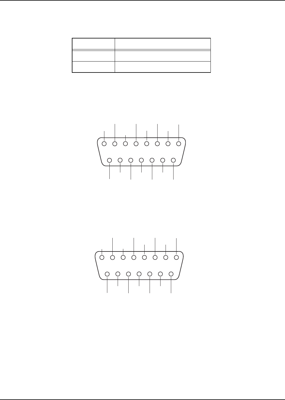
6878215A01
4-12 Options and Accessories Installation Memory and Three-Day Secure Key Retention Option
4.5.2 Adapter Cable
If you are planning on installing an APX mobile radio as a replacement for an ASTRO Spectra radio,
the following adapter cables are available:
NOTE: The adaptor cables can only be connected to J2 in the rear of the transceiver.
Use the HKN6158_ audio adapter kit cable if your vehicle was formerly wired for an ASTRO Spectra
or ASTRO Spectra Plus radio, and used the rear cable pins as shown in Figure 4-12.
Figure 4-12. Rear Accessory Connector Audio Configuration
Use the HKN6159_ data adapter kit cable if your vehicle was formerly wired for an ASTRO Spectra
or ASTRO Spectra Plus radio, and used the rear cable pins as shown in Figure 4-13.
Figure 4-13. Rear Accessory Connector Data Configuration
You must attach the correct adapter. Installing the wrong adapter may cause damage to the data
communication circuitry inside your radio. If you are unsure of the pinout of your former wiring
harness, please consult your ASTRO radio installation technician.
4.6 Memory and Three-Day Secure Key Retention Option
For the installation or removal of the Memory or 3-Day Secure Key Retention Options
(MHLN6999_ and MHLN7000_), see the APX Mobile Basic Service Manual (6875964M01).
NOTE: The Three-Day Secure Key Retention Option is not applicable for APX 2500/APX 4500.
Part Number Description
HKN6158_ Cable, Audio Adapter Kit
HKN6159_ Cable, Data Adapter Kit
VIP OUT 2
IGNITION
SPKR
LO - N.C.
GND SPKR
HI +
SWB+ EMER
N.C.
VIP OUT 1
MIC HI N.C.
PTT DISC.
AUD
N.C.
54321
9
1011121314
15
768
VIP OUT 2
IGNITION
SPKR
LO -
CTS-ASTRO
RTS_DCE
DIG
GND
SPKR
HI +
SWB+ EMER
BUS-VIP OUT 1
RTS-ASTRO
CTS_DCE
BUSY
TX-ASTRO
RX_DCE
RX-ASTRO
TX_DCE
BUS+
54321
9
1011121314
15
768
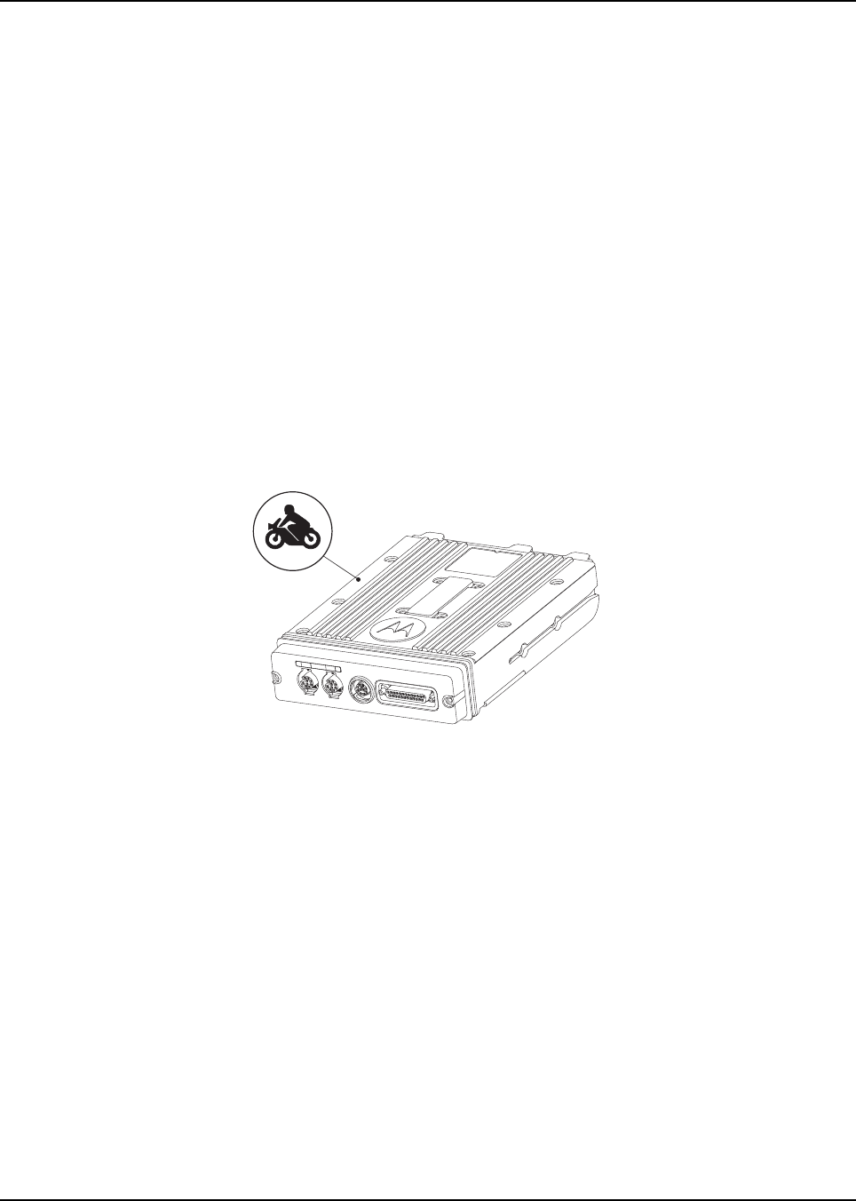
Chapter 5 Motorcycle Radio Installation
NOTE: The motorcycle radio installation is not applicable for 100W radios, APX 4500 radios and O9
control heads.
5.1 Motorcycle Radio Description
The motorcycle model includes all the same components in the standard radio, with the exceptions
listed in the model charts in the APX Mobile Basic Service Manual (6875964M01). The following
paragraphs describe the unique items provided with the motorcycle models.
NOTE: The APX Mobile Basic Service Manual (6875964M01) includes complete parts lists and parts
numbers for all parts shown in the exploded views in this chapter.
A small label is included with the motorcycle radio, which can be placed on the radio to identify
it as a motorcycle radio. The label should be placed on a flat and protected area to avoid
damage during handling. See Figure 5-1.
Figure 5-1. Identification of a Motorcycle Radio by Using a Label
5.1.1 Transceiver Enclosure
The transceiver is mounted in the weather-resistant enclosure that consists of a bottom housing and
a hinged top cover. The top cover has a locking latch that requires a key to open. The enclosure is
mounted above the rear motorcycle wheel, oriented so that the lock is forward and the hinged cover
opens toward the rear of the motorcycle. The bottom housing has a grommeted hole for cable entry
and weep holes to permit water drainage.
The enclosure is mounted on the motorcycle with a universal mounting plate and shock and vibration
isolators. A large, braided ground-strap (installed between the mounting plate bolts and the
motorcycle frame) grounds the transceiver.
5.1.2 Control/Display Unit
All radio functions, except push-to-talk (PTT), are activated from the control head, which also is
weather-resistant. The control head and the external speaker are mounted for easy access near the
center of the handlebars. The control head is positioned for unobstructed viewing, and it may be
tilted on the horizontal axis for ease of viewing. The microphone cable port on the front of the control
head is plugged and is not used.

6878215A01
5-2 Motorcycle Radio Installation Motorcycle Radio Description
5.1.3 Control Head Cable
The control-head cable connects the control head to the transceiver. The cable is routed along the
motorcycle’s frame and has weather-resistant connections at both ends. Excess cable is coiled
under the transceiver inside the weather-resistant enclosure.
Each end of the cable is strain-relieved with jackscrews at the control head and the transceiver.
The cable is shielded to reduce the effects of radio frequency interference and ignition sense noise.
5.1.4 Microphone
A weather-resistant, palm microphone and coiled cord plug into a pigtail connector on the control
cable. The microphone attaches to a hang-up bracket located within easy reach of the motorcycle
rider. The coiled cord is long enough to be operated by someone standing next to the motorcycle, yet
short enough to not interfere with the motorcycle’s steering or operation.
5.1.5 Keypad Mic
The Mobile Keypad Microphone (Mic) is a full keypad handheld microphone. The keypad on this
microphone is intended to assist in navigating through the menus on its parent device, as well as
entering information such as phone numbers and menu picks.
5.1.6 External Speaker
A 3.2-ohm, 10-watt-rated-audio-power, external speaker is mounted on the front of the motorcycle.
The speaker cable is routed along the motorcycle frame to the transceiver’s rear accessory
connector. A sealed, weather-resistant, speaker-muting (toggle) switch is mounted on top of the
speaker.
The external speaker connects to the rear accessory connector of the transceiver.
5.1.7 Headset Capability
The motorcycle radio is compatible with headset accessories that would provide hands-free
operation of the radio. Motorola does not manufacture headset equipment, but provides the
interconnection for headset equipment with the motorcycle radio. Aftermarket headset equipment is
available through Motorola (see Appendix A: Replacement Parts Ordering).
5.1.8 Antenna
The antenna(s) are mounted on top of the transceiver’s weather-resistant enclosure.
The enclosure’s metal lining acts as the antenna’s ground plane.
5.1.9 Ignition Sense (ACC) Wire
The ignition sense wire connects to the motorcycle’s fuse box and is routed along the motorcycle
frame to the transceiver’s rear accessory connector.
The radio is wired so that transmission is inhibited if the motorcycle’s ignition sense switch is off.
If the PTT switch is pressed with the ignition sense off, a low-frequency tone sounds. The receiver is
controlled by the control head on/off switch.
To avoid possible injury to hearing, the audio setting in the mobile radio MUST be
confirmed, if the Motorola mobile radio is used with any motorcycle helmet headset.
See CPS Help for details.
!
C a u t i o n

6878215A01
Motorcycle Radio Installation Installation Overview 5-3
5.2 Installation Overview
5.2.1 General
All APX mobile radios are tested and inspected before shipment. It is, however, suggested that the
transmitter frequency, deviation, and power output be checked at the time of installation. It is the
license holder’s responsibility to ensure that the operating parameters of his station comply with
applicable laws governing radio communications equipment. For tests and alignment procedures,
refer to the appropriate service manual (refer to “Related Publications” on page vi).
Generally, the installation of the motorcycle radio takes place in the following parts:
• Mounting the universal mounting plate and related hardware at the rear of the motorcycle;
• Mounting the control head, speaker, microphone, and related hardware forward on the
motorcycle;
• Routing the power cable, control-head cable, speaker cable, and ignition sense cable to the
weather-resistant enclosure;
• Mounting the weather-resistant enclosure and radio chassis, and connecting the cables;
• Mounting the antenna(s) to the weather-resistant enclosure.
A universal mounting plate, supplied by Motorola, is first mounted to either a motorcycle carrier at the
rear of the motorcycle or to the rear frame of the motorcycle itself. The mounting procedures for the
universal mounting plate vary from motorcycle to motorcycle. Therefore, the procedures given in this
manual for installing the mounting plate may not specifically apply, but are provided for guidance.
The control head, speaker, and microphone are mounted forward on the motorcycle, on or near the
steering column. There are several possible mounting configurations which use a combination of
Motorola and customer-built brackets. These configurations are outlined in this manual. Because of
the large number of motorcycle makes and models in existence, the customer-built brackets are
necessary to tailor the mounting of the Motorola equipment to the particular motorcycle being used.
Suggestions for customer-built brackets are given in this manual.
The power cable, control-head cable, speaker cable, and ignition sense cable are routed to the
weather-resistant enclosure position. The enclosure and the radio chassis are then mounted. Special
care is required when connecting cables to the radio equipment within the enclosure.

6878215A01
5-4 Motorcycle Radio Installation Installation Overview
5.2.2 Important Installation Hints
Consider the following when mounting the radio components:
• Excess lengths of control-head, power, ignition sense, and speaker cables must be routed in
the enclosure as shown in Figure 5-16.
• All components must be mounted securely in order to withstand the constant and sometimes
severe vibration experienced on a motorcycle.
• No cantilever action, which could cause severe vibration, should be generated in the mounting
hardware.
• The control head and microphone must be placed for ease of accessibility by the motorcycle
operator.
• Forward components (control head, microphone, and speaker) should not interfere with visual
or physical access to controls and instruments.
• Forward components should not interfere with the handling of the motorcycle.
• Cabling between the control head and the radio chassis should be run to minimize interference
with operator movements.
• The weather-resistant enclosure should be placed to avoid any interference with the motorcycle
operator.
• Electrical continuity must be present through the enclosure shock mounts to the motorcycle
frame for proper electrical and RF grounding.
• The antenna(s) are designed for mounting on the top of the weather-resistant enclosure.
• Only the supplied microphone mounting clip should be used to ensure secure mounting of the
microphone. This clip has a very strong spring to ensure positive retention of the microphone
over rough terrain. Also, there must be electrical continuity from this clip to the motorcycle
frame for DC grounding.
• Direct access to the microphone should be provided from both sides of the motorcycle.
• Sufficient slack in the microphone coiled cord should be allowed so as not to impede steering.
• Mounting hardware must be stainless steel to prevent corrosion.
• If an extra length of cable is used to extend the microphone, ensure that the added capacitance
does not interfere with the operation of the radio.

6878215A01
Motorcycle Radio Installation Installation Overview 5-5
5.2.3 Parts Identification
The following installation procedures refer to Figure 5-2 through Figure 5-17. Detailed descriptions of
the mounting hardware used in each procedure are provided in parts lists located in the exploded
views located in the APX Mobile Basic Service Manual (Motorola publication part number
6881096C73). Those parts supplied by Motorola are contained in one of the following kits:
• Motorcycle Weather-Resistant Microphone
• Motorcycle Weather-Resistant Speaker with Mute Switch
• Motorcycle Weather-Resistant Speaker with Keypad Mic
• Motorcycle Hardware Kit SECURENET or Motorcycle Hardware Kit
• Motorcycle Power Cable Kit
• Motorcycle Mounting Kit
• Weather-Resistant Enclosure (Black)
• Antenna
5.2.4 Order of Installation
Before starting the installation, familiarize yourself with the mounting hardware (see Figure 5-2
through Figure 5-17). Perform the installation procedures in the order that follows.
1. Install the universal mounting plate on the motorcycle.
2. Install the control head and speaker.
3. Install the microphone hang-up clip.
4. Install antenna base and cable onto enclosure.
5. Install the cables.
6. Install the weather-resistant enclosure on the universal mounting plate.
7. Route the cables inside the weather-resistant enclosure.
8. Install the transceiver in the weather-resistant enclosure.
9. Install the antenna(s) on the enclosure.
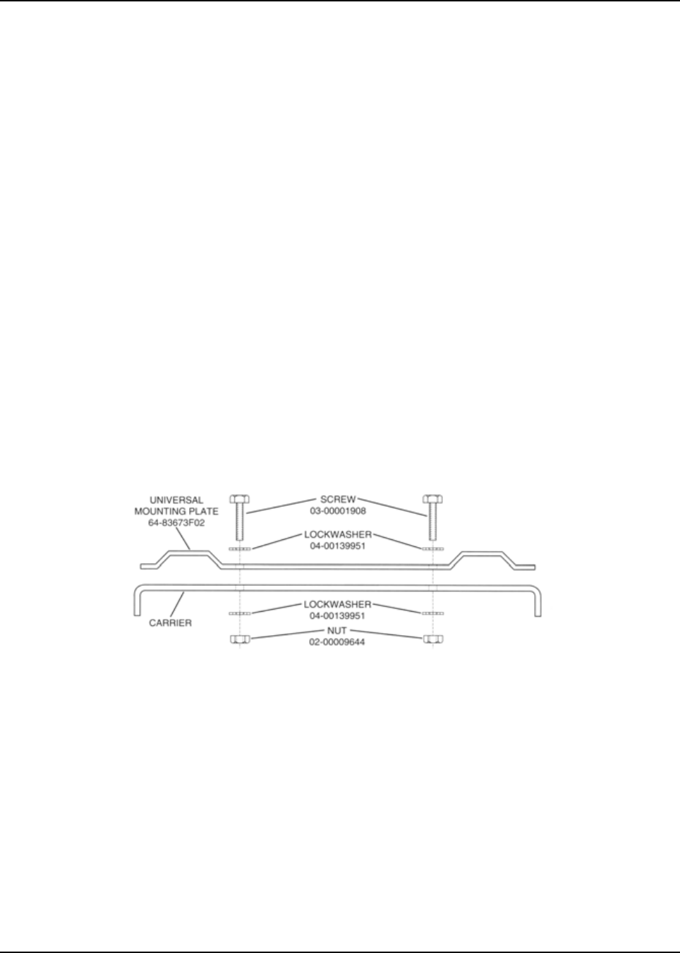
6878215A01
5-6 Motorcycle Radio Installation Installing the Universal Mounting Plate
5.3 Installing the Universal Mounting Plate
The universal mounting plate, supplied with the motorcycle radio, must be mounted on the
motorcycle first. It provides the base on which the weather-resistant enclosure is to be mounted.
The method used for mounting the plate depends on the make and model of the motorcycle and
whether the plate is mounted to a carrier or to the motorcycle chassis. After the plate has been
securely mounted to the motorcycle, mounting the weather-resistant enclosure onto the plate is
straightforward.
Figure 5-2 illustrates the universal mounting plate mounted to a motorcycle carrier. Since there are
so many makes and models of motorcycles and motorcycle carriers, it is impossible to give specific
step-by-step instructions for mounting the universal mounting plate. However, noting the following
considerations will aid in the installation procedure.
• A minimum of holes are predrilled into this plate as supplied. Mounting holes must be drilled as
required for the particular motorcycle on which the plate is being mounted.
• The universal mounting plate should be mounted on the motorcycle in such a manner that the
later mounting of the weather-resistant enclosure will not interfere with the motorcycle seat
back, with any other obstacles, or with the motorcycle operator. The enclosure may be
temporarily bolted to the universal mounting plate and the unit positioned on the motorcycle to
ensure the above criteria are met.
• To ensure a good grounding path from the universal mounting plate to the motorcycle carrier or
frame, stainless steel lock washers must be used with the mounting hardware in two areas to
score through the paint on the universal mounting plate and on the carrier or frame, thereby,
providing good electrical contact with the underside of the motorcycle carrier or motorcycle
frame.
Figure 5-2. Universal Mounting Plate Installation (Part of Radio Enclosure Kit)
Follow the procedures below to mount the universal mounting plate to the motorcycle
(see Figure 5-2).
1. Determine the mounting position for the mounting plate.
2. Determine whether stainless steel spacers are required for clearance in mounting the plate.
3. Drill four 9/32-inch holes in the mounting plate and the corresponding motorcycle carrier or
chassis for mounting the plate.
4. Attach the universal mounting plate to the motorcycle using four machine screws, eight lock
washers, and four nuts. Tighten screws securely. The lock washers must cut through the
paint on the plate and motorcycle carrier or frame to ensure a good ground path.
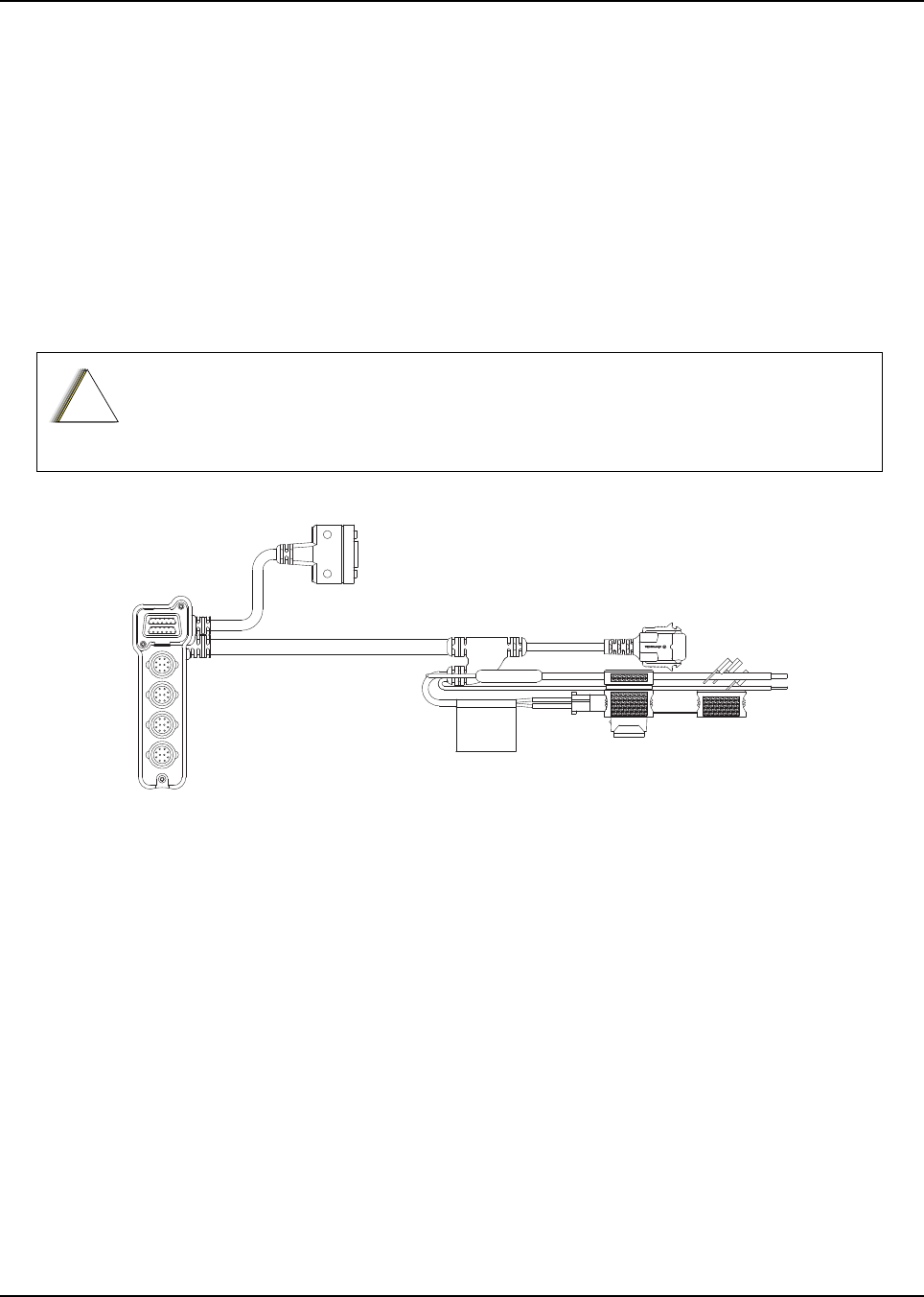
6878215A01
Motorcycle Radio Installation Installing the Speaker and Control Head 5-7
5.4 Installing the Speaker and Control Head
NOTE: To disable the internal speaker of the O2 Control Head, please refer to Section 2.5.1: “Internal
Speaker Disassembly” on page 2-44.
The control head mounting location and configuration is determined largely by the make and model
of motorcycle. Two different mounting configurations are described below. One involves mounting
the speaker and control head together as a unit using the combination speaker/control-head bracket
(shown in Figure 5-4) supplied by Motorola. Alternately, the control head may be mounted by itself
using a smaller control-head bracket supplied by Motorola. In this case, the speaker is mounted
elsewhere. This section outlines installation procedures for each configuration mentioned above.
The customer (or installer) is in the best position to determine the most appropriate mounting
configuration for the control head and speaker based on the particular motorcycle on which the
equipment is to be mounted.
Figure 5-3. Motorcycle Control Head Cabling (3075217A01)
When determining its location, position the control head so that it is clearly visible and
within easy reach of the motorcycle operator.
!
C a u t i o n
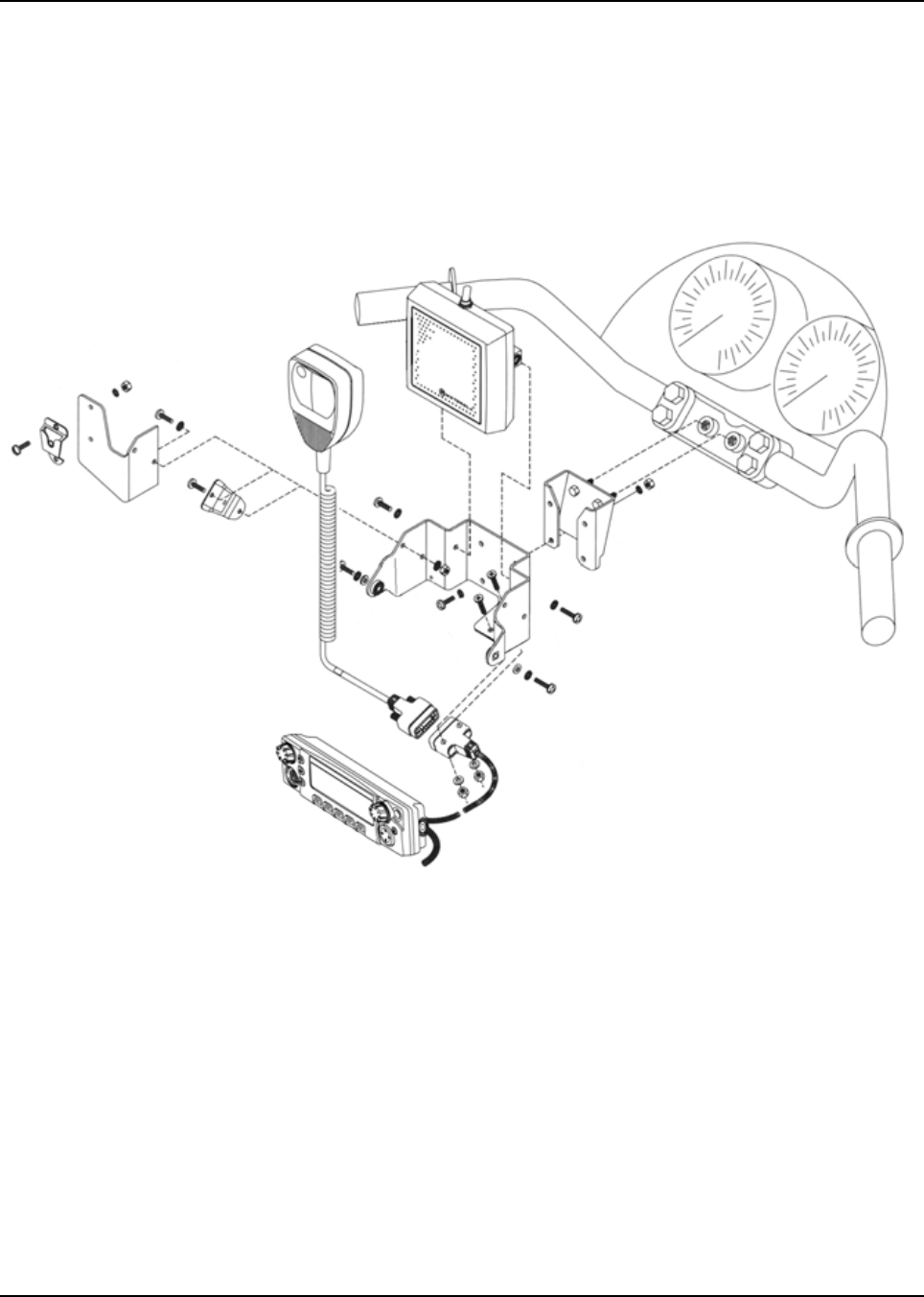
6878215A01
5-8 Motorcycle Radio Installation Installing the Speaker and Control Head
5.4.1 Handlebar Installation with Speaker and Control Head Mounted Together
Figure 5-4 illustrates the combination speaker/control head bracket. This combination bracket is
used only when the control head and speaker are to be mounted as a unit. Also illustrated in
Figure 5-4 is a handlebar-mounting bracket which may be required if the combination speaker/
control-head bracket cannot be easily mounted to the motorcycle. In this case the
handlebar-mounting bracket is mounted to the motorcycle, and the combination bracket is then
mounted to the handlebar-mounting bracket.
Figure 5-4. Handlebar Installation with Speaker and Control Head Mounted Together

6878215A01
Motorcycle Radio Installation Installing the Speaker and Control Head 5-9
Provision has been made on the combination speaker/control-head bracket for mounting the
microphone hang-up clip. If that mounting is desired, the hang-up clip must be attached to the
bracket before installing the control head and speaker. See Section 5.6: “Installing the Microphone
Hang-Up Clip” on page 5-14 for the hang-up clip procedure. Install the speaker and control head as
described below.
1. Determine the location where the speaker/control head is to be mounted. Consider how the
speaker/control-head bracket may be mounted, and whether or not a handlebar-mounting
bracket is needed. Take care to select a location that is not only mechanically convenient, but
is located for ease of operation.
NOTE: The angle at which the handlebar-mounting bracket or the speaker/control-head bracket is
mounted to the motorcycle determines the firing angle of the speaker.
2. If the handlebar-mounting bracket is needed, install it first.
3. Mount the speaker/control-head bracket, either directly to the motorcycle, or, if used, to the
handlebar-mounting bracket, using four stainless-steel machine screws, lock washers, and
nuts.
4. Mount the 9-pin D-connector end of the motorcycle control-head cable to the speaker/control
head bracket, using two machine screws, flat washers, and nuts. (Cable routing directions
appear later in this section.)
5. Mount the speaker on the speaker/control-head bracket, using two machine screws and lock
washers. Torque these screws to 20 in-lbs.
6. Attach the control-head cable to the control head and tighten the locking screws on the
connector. This connection must be made before you mount the control head in the bracket.
(Cable routing directions appear later in this section.)
7. Mount the control head to the bracket, using two machine screws, lock washers, and flat
washers.
8. Adjust the control head viewing angle by loosening its mounting screws and rotating the
control head to the desired angle. Then, retighten screws to 20 in-lbs torque. This concludes
the speaker/control-head installation.
5.4.2 Fuel Tank Console Installation with Speaker and Control Head Mounted
Together
Some motorcycles provide a console for mounting radio equipment. This console is attached to the
top of the fuel tank. With the use of a mounting bracket, screws, nuts, and lock washers, the
combination speaker/control-head bracket can be mounted to this console. Figure 5-5 illustrates this
type of mounting.
The console attachment screws must be removed, and the console must be lifted slightly from the
fuel tank to gain access in order to attach mounting hardware, and to route cables later.
In this installation, the microphone (mic), mic hang-up bracket, and mic extension bracket will
interfere with handlebar travel.
Installation using this method is the same as in Section 5.4.1: “Handlebar Installation with Speaker
and Control Head Mounted Together” on page 5-8.
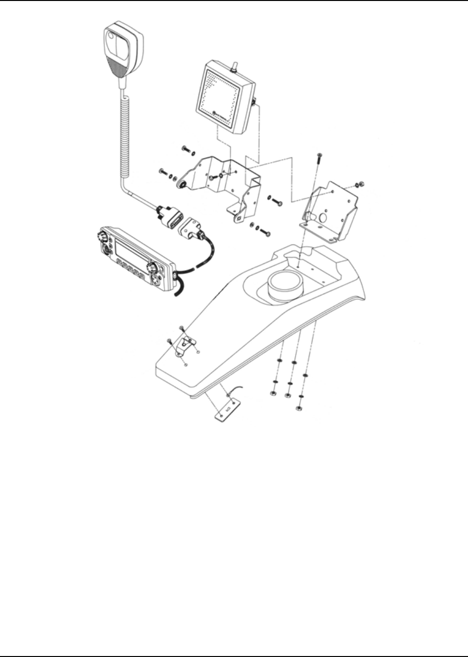
6878215A01
5-10 Motorcycle Radio Installation Installing the Speaker and Control Head
Figure 5-5. Fuel Tank Console Installation with Speaker and Control Head Mounted Together
f

6878215A01
Motorcycle Radio Installation Installing the Speaker and Control Head 5-11
5.4.3 Handlebar Installation with Speaker and Control Head Mounted Separately
It may be necessary to use the smaller control head bracket (part number 07-80127N02) and mount
the speaker and microphone hang-up clip in another location on the motorcycle.
Before installing the control head using the bracket described above, the control-head end of the
control-head cable should be temporarily fastened to the control head, and the control head fastened
to its bracket. Motorola-supplied spacers and the mic-cable bracket are required to mount the control
head to the handlebar. This mic-cable bracket has holes to mount the microphone-cable connector.
Follow these procedures when mounting the smaller control-head bracket:
1. Determine the location at which the control head is to be mounted. Take care to choose a
location that is not only mechanically convenient, but is located for ease of operation.
2. Securely mount the Motorola-supplied spacers, mic-cable bracket, and small control-head
bracket to the handlebars.
3. Mount the 9-pin D-connector end of the motorcycle control-head cable to the mic-cable
bracket, using two machine screws, flat washers, and nuts. (Cable routing directions appear
later in this section.)
4. Attach the control-head end of the cable to the control head and tighten the locking screws on
the connector.
5. Mount the control head to the small control-head bracket, at the proper viewing angle, using
two wing screws. Tighten firmly. This concludes the control-head installation.
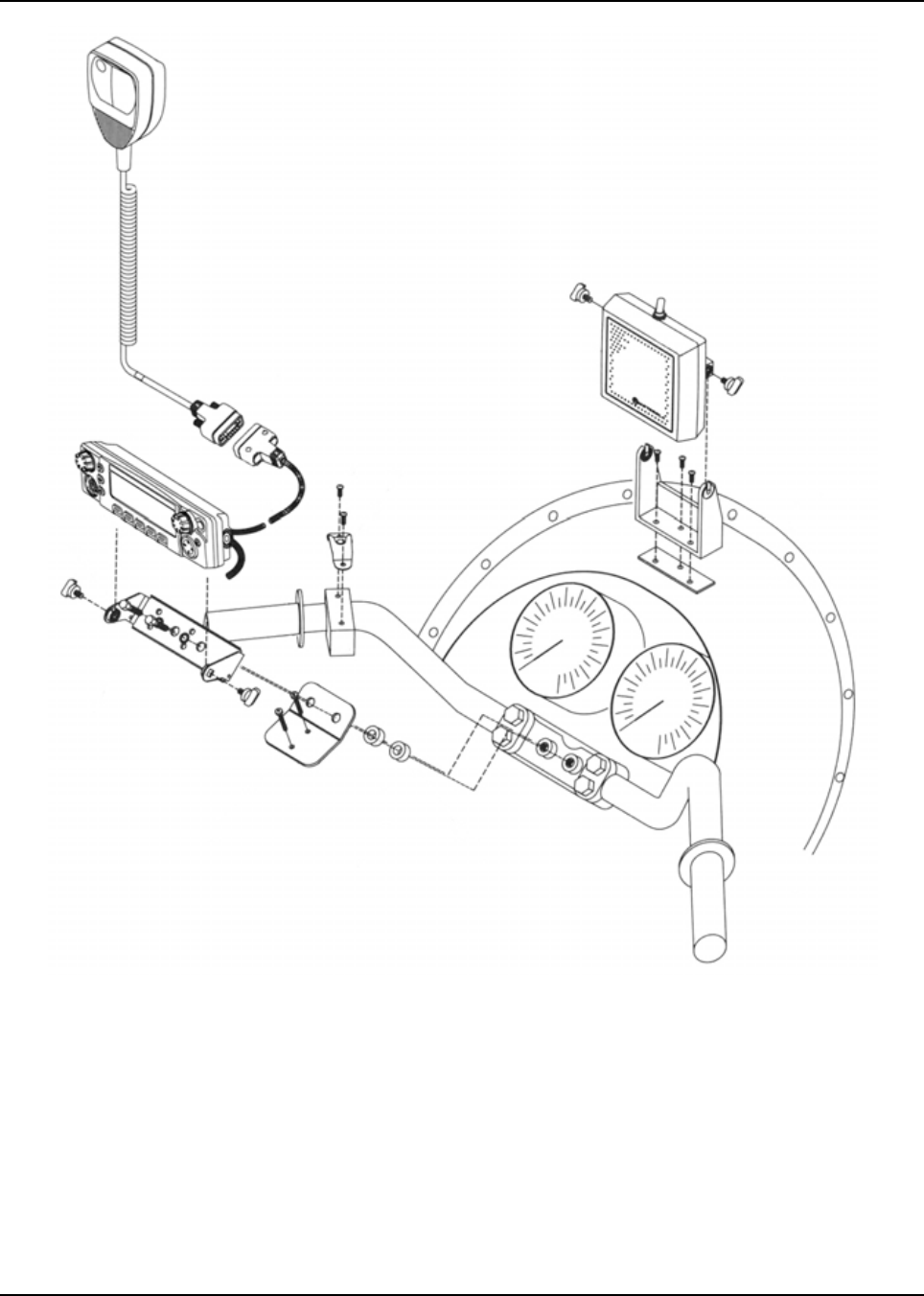
6878215A01
5-12 Motorcycle Radio Installation Installing the Speaker and Control Head
Figure 5-6. Handlebar Installation with Speaker and Control Head Mounted Separately
5.4.4 Fuel Tank Console Installation with Speaker and Control Head Mounted
Separately
The control head may be mounted to the fuel tank console using the smaller control-head bracket
and spacers/hardware. In this configuration, the microphone cable connector may be attached
directly to the console, eliminating the need for a custom bracket.
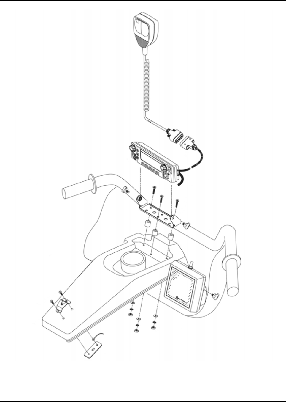
6878215A01
Motorcycle Radio Installation Installing the Speaker and Control Head 5-13
Figure 5-7. Fuel Tank Console Installation with Speaker and Control Head Mounted Separately
Installation is the same as detailed in Section 5.4.2: “Fuel Tank Console Installation with Speaker and
Control Head Mounted Together” on page 5-9 and Section 5.4.3: “Handlebar Installation with
Speaker and Control Head Mounted Separately” on page 5-11.

6878215A01
5-14 Motorcycle Radio Installation Installing the Speaker
5.5 Installing the Speaker
NOTE: To disable the internal speaker of the O2 Control Head, please refer to Section 2.5.1: “Internal
Speaker Disassembly” on page 2-44.
Use the following procedure when the speaker is mounted separate from the control head. The
speaker bracket supplied with the speaker may be used alone if a suitable location can be found, or
if necessary, a customer-supplied bracket may be fabricated for mounting the speaker.
1. Determine the location in which the speaker is to be mounted and whether there is a
requirement for a customer-supplied bracket.
2. Fabricate a bracket if required. Use the Motorola-supplied speaker bracket as a template for
drilling mounting holes. Also drill holes in the fabricated bracket for mounting to the
motorcycle.
3. Mount the fabricated bracket to the motorcycle chassis.
4. Mount the Motorola-supplied bracket to the fabricated bracket using two machine screws, flat
washers, lock washers, and nuts.
5. Mount the speaker to the speaker bracket using two wing screws. Directions for speaker
cable routing appear later in this section. Speaker mounting is now complete.
5.6 Installing the Microphone Hang-Up Clip
Install the hang-up clip either on the supplied microphone extension bracket or on the side of the
speaker/control head bracket. Both methods are shown in Figure 5-4. Determine the mounting
location and install as described in the following paragraphs.
NOTE: Wherever the hang-up clip is mounted, it must be DC grounded for proper operation. After
mounting the clip, be sure there is electrical continuity between the clip and the motorcycle
chassis.
5.6.1 Extension Bracket Mounting
Using this method, you can mount the clip so that it faces the operator.
1. Attach the bracket to the speaker/control-head bracket using two machine screws, four lock
washers, and two nuts as shown in Figure 5-4.
2. Torque nuts to 20 in-lbs torque.
3. Fasten the hang-up clip to the extension bracket using two machine screws, lock washers,
and nuts as shown in Figure 5-4.
4. Torque nuts to 20 in-lbs torque.
5.6.2 Speaker/Control Head Bracket Side Mounting
Attach the hang-up clip to the left side of the speaker/control-head bracket using two machine
screws, lock washers, and nuts as shown in Figure 5-4. Torque nuts to 20 in-lbs. torque.
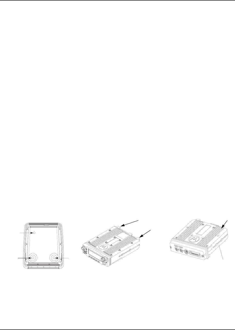
6878215A01
Motorcycle Radio Installation Installing Antenna Base and Cables 5-15
5.6.3 Other Hang-Up Clip Mounting
To mount the microphone hang-up clip in another location, a customer-supplied bracket may be
used. Suggested locations include the handlebars, fuel-tank console, or any location which provides
easy access to the microphone without blocking controls and indicators and without interfering with
motorcycle handling. See Figure 5-5, Figure 5-6, and Figure 5-7 for alternative microphone hang-up
clip mounting methods.
1. Fabricate a bracket, then secure it to the motorcycle.
2. Use two machine screws, lock washers, and nuts to secure the hang-up clip to the
customer-supplied bracket. Ensure that the microphone clip is DC grounded to the
motorcycle chassis (a grounding lug and strap are provided in the hang-up clip kit for this
purpose) – this is essential for proper radio operation.
5.7 Installing Antenna Base and Cables
NOTE: Antenna hole placement and cable routing in 7/800, VHF and UHF antenna manuals are not
applicable for the APX Series.
The GPS antenna assembly must be done after the removal of the metal liner but before
reinstalling the APX Series liner.
1. Open the top cover of the weather-resistant enclosure.
2. Uninstall the metal liner that is shipped attached to the weather-resistant enclosure. This liner
has one depressed area at the top of the enclosure liner just toward the rear of the enclosure.
This metal liner is not used with APX Series products.
3. Place the metal liner with two round, depressed areas toward the enclosure hinge and 5/8”
hole near the front of the housing, inside the top cover, and align the six slots in the metal
liner with the screw holes in the top housing.
4. The metal liner of the enclosure’s top cover acts as a ground plane for the antenna.
5. Locate the two round, depressed areas about 3 inches in diameter in the metal liner near the
enclosure hinge. Referring to Figure 5-8, these areas are either Band 1 or Band 2 depending
on the antenna port they align to. Refer to band markings on radio for the proper antenna port
location. For the GPS antenna, use the 5/8” hole near the front of the housing near the lock.
Figure 5-8. Location of Band 1 or Band 2 (Depending on the Antenna Port They Align to)
GPS
Band 2
A
ntenna
Band 1
Antenna
Band 1 Antenna Port
Band 2 Antenna Port
Top Cover for APX Radios Antenna Port
ASTRO 25 Subscribers
APX 2500/APX 4500
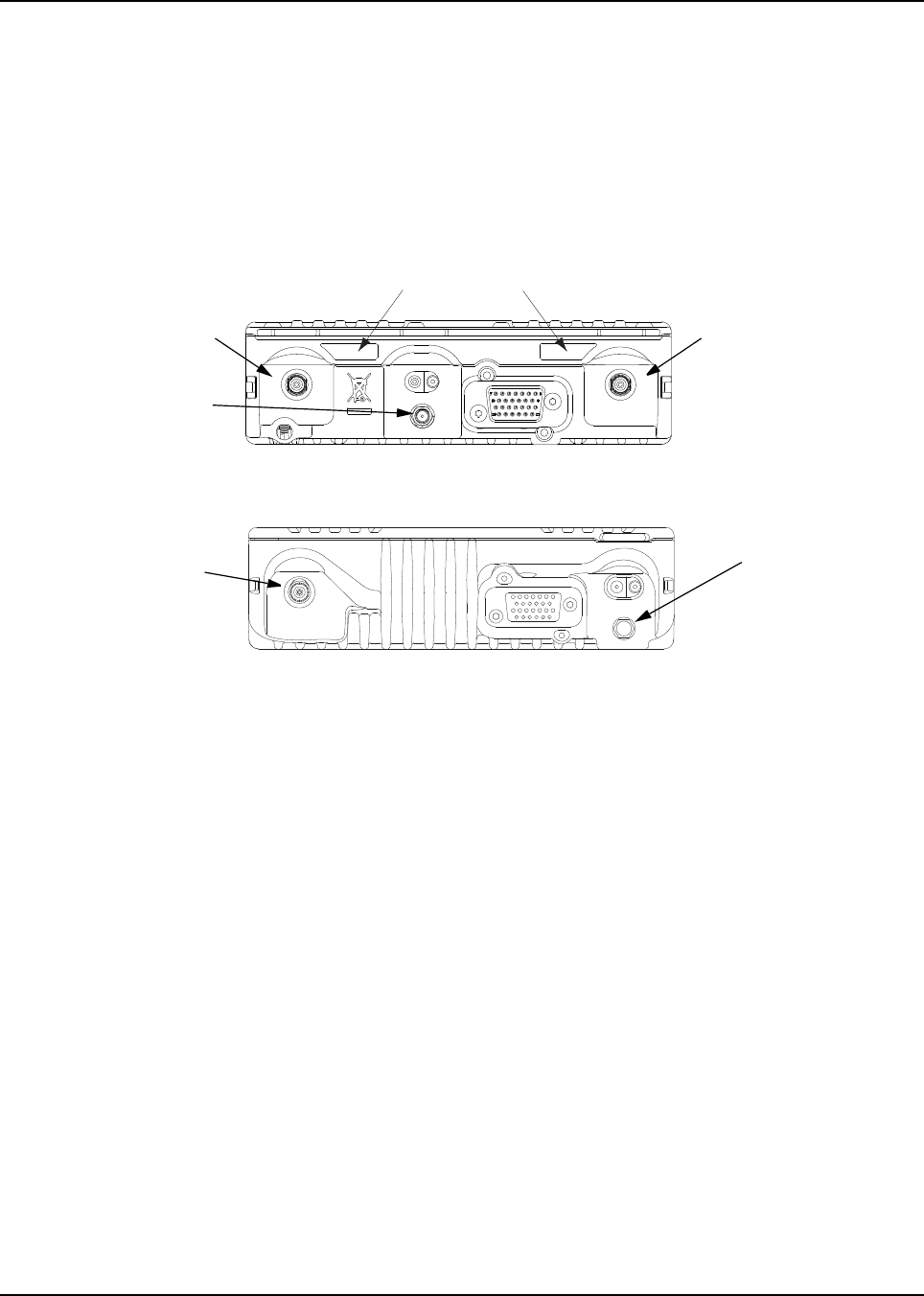
6878215A01
5-16 Motorcycle Radio Installation Installing Antenna Base and Cables
6. These holes in the metal liner is used as a template to mark the position of the hole(s) to be
drilled at the top cover. Follow the below guidelines for the various options.
-Single Band – Refer to your APX radio (see Figure 5-9 or Figure 5-10) and see if your
single band antenna is in the position of Band 1 or 2. Depending on which location your
antenna port is mark a hole in the appropriate antenna position only. Refer to Figure 5-8.
-Dual Band – Mark a hole in both the Band 1 and Band 2 Antenna position as seen on
Figure 5-8.
-GPS – Mark a hole in the GPS Antenna position as seen on Figure 5-8.
Figure 5-9. Antenna Band Identification
Figure 5-10. APX 2500/APX 4500 Antenna Band Identification
7. Remove the metal liner from the top cover.
8. For Band 1 and Band 2 positions, use the Motorola RPX-4378A Hole-Cutting Saw or
equivalent, and carefully drill a 3/4-inch hole at the marked location from the inside of the
cover until the saw bottoms out. For the GPS carefully drill a 9/16-inch hole at the marked
location from the inside of the cover until the saw bottoms out. The saw should clean a neat
circle to assure good contact between the antenna and the housing.
IMPORTANT: For proper seating of the antennas, deburr and scrape any foreign
matter from both sides of the hole, being careful not to mar the
finish of the shell.
9. Clean the mounting surface around the hole to remove dirt and wax.
10. Refer to the Motorcycle GPS Instruction Manual for further installation instruction for the
GPS. GPS must be mounted before the APX metal liner is installed.
11. Reinstall the APX metal liner (see Figure 5-8) with the cable clamps provided in the weather-
resistant housing. If installing GPS, the GPS coaxial cable must be fed through the hole in the
APX metal liner before the liner can be placed onto the housing. Then route the GPS Coaxial
Cable through the cable clamps before tightening the hex screws as installing the cable after
that is difficult due to the connector. See Figure 5-11 for GPS Cable Routing.
Antenna Band Label
Band 1 Antenna PortBand 2 Antenna Port
GPS Antenna Port
Antenna Port
GPS Antenna Port
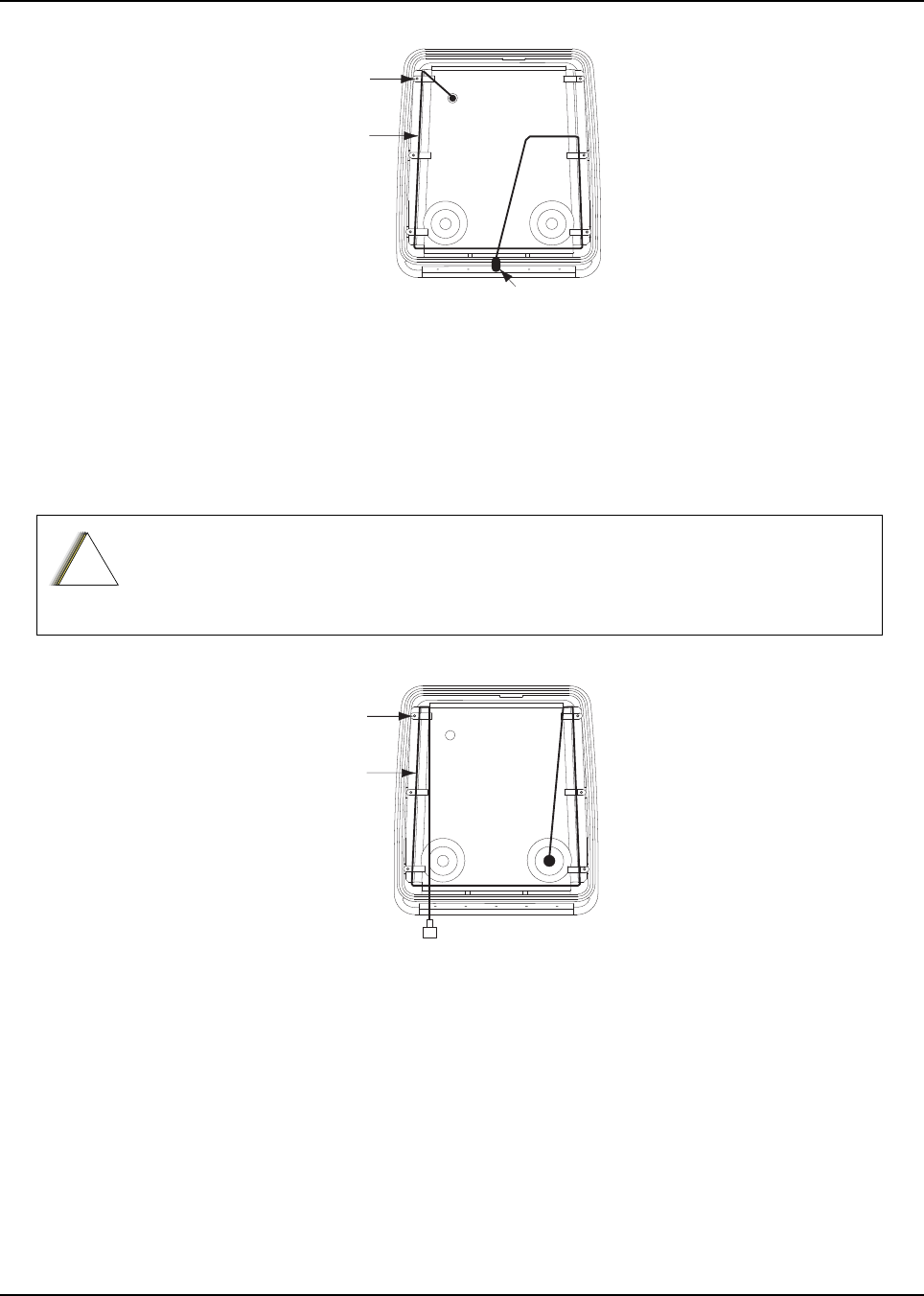
6878215A01
Motorcycle Radio Installation Installing Antenna Base and Cables 5-17
Figure 5-11. Routing the Coaxial Cable for GPS
12. Attach the 7/800, VHF or UHF antenna base per Antenna Installation Manual.
IMPORTANT: Antenna Placement and Cable Routing in the Antenna Installation
Manual is not applicable for the APX series.
13. Route the coaxial cable for the 7/800, VHF or UHF antenna(s) through the cable clamps per
Figure 5-12 for Band 1 and Figure 5-13 for Band 2.
Figure 5-12. Routing the Coaxial Cable for Band 1
Be sure to observe the correct routing of the antenna cable. Failure to do so can damage the
cable.
Cable
Clamp
Coaxial
Cable
Connector
!
C a u t i o n
Cable
Clamp
Coaxial
Cable
Attach to Antenna
Connector on
Radio Band 1
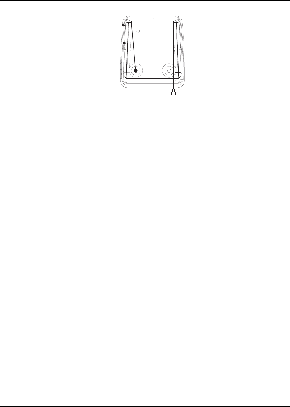
6878215A01
5-18 Motorcycle Radio Installation Installing the Antenna
Figure 5-13. Routing the Coaxial Cable for Band 2
14. After routing cable, allow enough of the cable to reach the radio’s antenna connector and cut
off any excess length of the cable.
15. Install the connector per Antenna Installation Manual.
5.8 Installing the Antenna
IMPORTANT: Antenna Placement and Cable Routing as described inside the
Antenna Installation Manual is not applicable for the APX radio
series. Refer to information listed below.
• Connect the appropriate antenna connectors to the antenna receptacles on the radio. Tighten
the coupling until fully engaged.
5.9 Cable Routing
Five cables must be installed to interconnect the components of the radio system as shown in
Figure 5-14. The antenna cable is routed away from the other cables inside the enclosure’s hinged
cover (see Section 5.7 on page 5-15). The four remaining cables, routed along the motorcycle frame,
are described in the following paragraphs.
NOTE: Antenna Hole Placement and Cable Routing information in the Antenna Installation Manual
is not applicable to the APX series.
Removal of the fuel tank and seat from the motorcycle will facilitate routing the cables along
the frame. Motorcycles with consoles attached to fuel tanks require routing cables between
console and fuel tank. In this case the tank is not removed.
Cable
Clamp
Coaxial
Cable
Attach to Antenna
Connector on
Radio Band 2
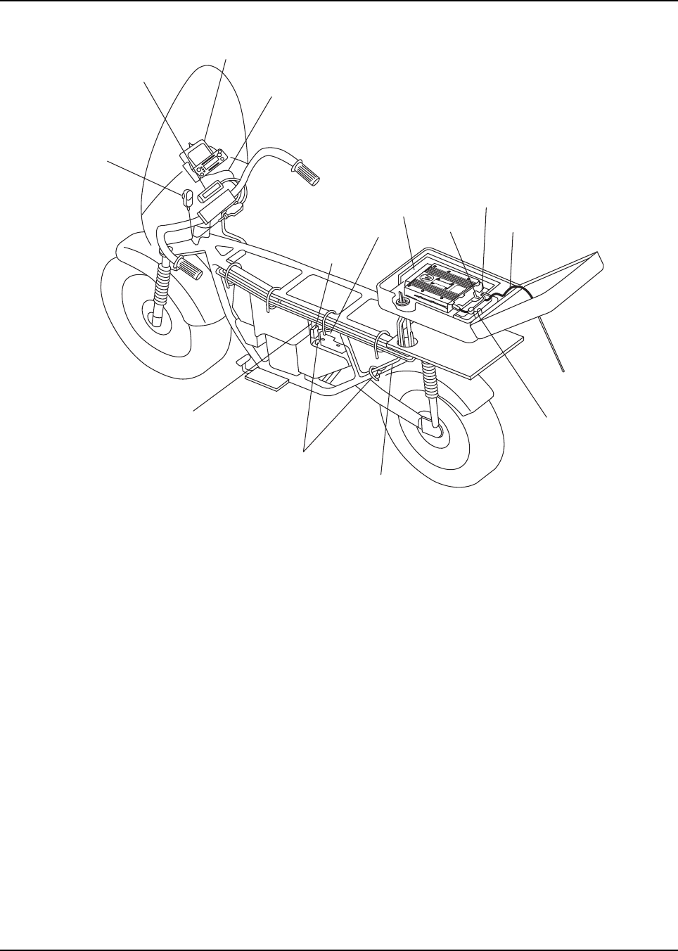
6878215A01
Motorcycle Radio Installation Cable Routing 5-19
Figure 5-14. Cable Routing
1. Speaker Cable – runs from the speaker to the accessory-cable connector inside the
weather-resistant enclosure.
2. Control Cable – runs from the rear of the control head to the front of the transceiver inside
the enclosure.
3. Ignition Sense (Red) Wire Portion of Accessory Cable – runs from the ignition sense fuse
terminal of the fuse box to the rear area inside the enclosure. The lug for attaching the ignition
sense wire is contained on the accessory cable.
4. Power Cable – The red, unterminated end runs from the positive terminal of the battery to
the power connector that plugs in the rear of the transceiver. Lugs for attaching the red and
black leads are contained in the motorcycle power-cable kit. The black, unterminated end
runs from a suitable motorcycle chassis ground to the power connector. DO NOT connect the
black lead directly to the negative battery post.
You may route the cables in any order. As you route each cable, temporarily fasten it at both ends.
When all cables have been run, permanently fasten the cables with appropriate cable tie wraps.
Observe the following during routing and hook-up:
1. Route the cables so that none interfere with motorcycle operation.
2. Fasten the cables with supplied nylon tie wraps. The wraps should be firmly installed at
frequent intervals along the cable length in such a manner that motorcycle vibration will not
cause metal fatigue and subsequent breakage of the cable wires.
CONTROL HEAD
CABLE
SPEAKER/
CONTROL HEAD
SPEAKER
CABLE
MICROPHONE
IGNITION
CABLE
CHASSIS GROUND
FUSED POWER
CABLE
SPEAKER
CABLE
ANTENNA
CABLE
ACCESSORY
CABLE
POWER
CABLE
CONTROL HEAD
CABLE
BATTERY
FUSE
BLOCK

6878215A01
5-20 Motorcycle Radio Installation Cable Routing
3. Take care to position cables away from parts of the motorcycle that get hot.
Bundle excess cable length inside the weather-resistant enclosure as discussed later in Section
5.11: “Transceiver and Cabling Installation” on page 5-22.
The fifth cable is the microphone with coiled cord. Plug the 9-pin D-connector end of the coiled cord
into its mating connector, which was attached near the control head discussed in an earlier
paragraph. Tighten the coiled-cord-retention screws. Insert the S-hook strain relief (terminated to the
coiled cord) into the hole in the mounting bracket. Slide the microphone into the microphone hang-up
bracket.
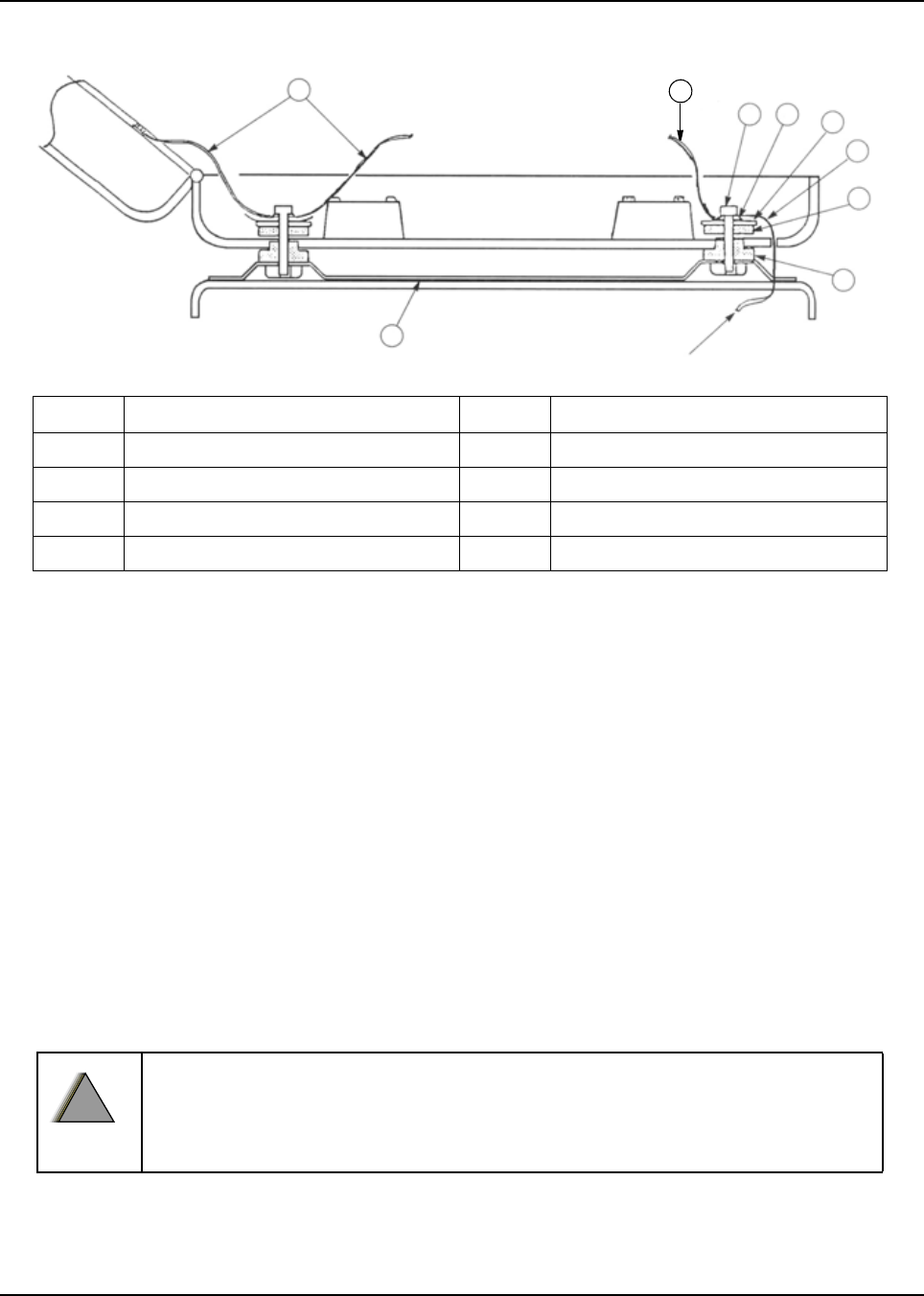
6878215A01
Motorcycle Radio Installation Installing the Weather-Resistant Enclosure 5-21
5.10 Installing the Weather-Resistant Enclosure
Figure 5-15. Weather-Resistant Enclosure Installation
1. Remove the radio-mounting plate by removing four screws, lock washers, and flat washers.
2. The weather-resistant enclosure is mounted to the universal mounting plate using shock
mounts. Assemble the shock-mount components exactly as shown in Figure 5-15. Be sure to
install ground straps between the shock-mount and the transceiver trunnion mount, and
install one 7-1/2-inch ground strap between the right rear mount and the enclosure lid’s
antenna ground plane 0 (shown in Figure 5-15 and in Figure 5-17).
3. The order of assembly is important to ensure proper shock mount operation. All components
are supplied with the mounting kit. The five 7- 1/2-inch straps are used on the rear and front
shock mounts – four from shock mount to trunnion, and one from the shock mount to the lid’s
antenna ground plane.
NOTE: Grounding through the power-supply cable is NOT sufficient. Whether the radio transceiver
is mounted to a carrier or the chassis itself, the transceiver MUST be properly grounded to
the motorcycle chassis. The ground strap supplied with the installation kit may have to be
used to ensure a good RF ground path from the radio transceiver to the motorcycle chassis.
4. Install the 3-foot ground strap on one of the front shock mounts. Route it through the cable-
routing hole and connect the other end to the motorcycle frame (see Figure 5-15).
DO NOT connect the ground strap directly to the negative battery post.
7
1
7
23 4
8
5
6
TO MOTORCYCLE
CHASSIS GROUND
Item No. Description Item No. Description
1 Universal Mounting Plate 5 Flat Rubber Washer
2 Machine Screw 6 Shouldered Rubber Washer
3 Lockwasher 7 7-1/2-inch Ground Strap
4 Flat Washer 8 Ground Strap
!
W A R N I N G
!

6878215A01
5-22 Motorcycle Radio Installation Transceiver and Cabling Installation
5. The diagram of the shock mount is shown loosely assembled. After the hex screws are
tightened, the rubber washers are compressed to fasten the weather- resistant enclosure
securely to the universal mounting plate.
6. Figure 5-17 is an exploded view of the enclosure; it shows details that will help to understand
how the enclosure is mounted. After the enclosure is completely mounted, check for proper
ground connection–continuity between the antenna ground plane and the motorcycle frame.
5.11 Transceiver and Cabling Installation
After the weather-resistant enclosure has been installed, the radio chassis (transceiver) is installed in
the enclosure and then appropriate cables are connected. However, before the transceiver can be
installed, the cabling must be properly positioned in the enclosure.
5.11.1 Installing Cabling in the Enclosure
Position the cabling in the weather-resistant enclosure as follows:
1. Run the speaker, power, control-head, and ignition sense cables into the enclosure.
2. Lay the excess cable length between the radio mounting bosses in an S configuration as
shown in Figure 5-16. Do not coil any excess cable. Use the supplied tie wraps to bundle
cable as shown.
NOTE: If the extra cable length is not sufficient to match the illustrated cable routing, then match the
illustration as closely as possible.
3. Connect the speaker cable to the accessory cable connector.
NOTE: The accessory-cable emergency connector is shipped with a shorting plug installed. The
headset connector is also shipped with a shorting plug installed. The plugs must remain in if
an emergency switch and/or headset is not used. If an emergency switch and/or headset is
used, remove the shorting plug(s) and discard.
4. Install the mounting plate in position on top of the cables installed above. Take care not to
damage or pinch the cables when securing the mounting plate in position.
NOTE: At this point, the control-head cable plug should be located at the forward end of the
enclosure, and the power-cable, speaker-cable, and accessory-cable plugs should be located
at the rear of the enclosure.
6878215A01
Motorcycle Radio Installation Transceiver and Cabling Installation 5-23
Figure 5-16. Installing Cables
5.11.2 Installing the Transceiver
Install the transceiver in the weather-resistant enclosure as follows (see Figure 5-17).
NOTE: For new or existing installations, use only the APX mobile trunnion (kit number: HLN7002_).
1. Install the mounting trunnion and loose ends of the four ground straps to the radio-mounting
plate, using four screws, flat washers, and external-tooth lock washers (see Figure 5-17). The
ground straps must be sandwiched between the flat washers and lock washers. The lock
washer must be against the trunnion. The flat washer must be under the screw head.
2. Attach the transceiver to the mounting trunnion and secure with the two screws provided.
3. Connect the control cable to the front of the transceiver. Ensure the control-cable connector
screws are tightened.
4. Attach the accessory connector to the transceiver. Plug in the power connector.
5. Install the grommet around the cables and push the grommet into the cable-routing hole of
the weather-resistant enclosure.
ACCESSORY
CABLE
TRANSCEIVER
POWER CABLE
ACCESSORY CABLE
EMERGENCY AND
EXTERNAL ALARM
CONNETOR
ACCESSORY
CABLE HEADSET
CONNECTOR
HEADSET
SPORTING PLUG
EMERGENCY
CABLE SHORTING
PLUG
IGNITION SENSE
(ACC)
CONTROL HEAD
GROUND (BLACK)
CONTROL HEAD
POWER FUSE
CONTROL CABLE
(CAN)
CONTROL HEAD
POWER (RED)
6878215A01
5-24 Motorcycle Radio Installation Transceiver and Cabling Installation
Figure 5-17. Installing the Transceiver
Table 5-1. Transceiver Installation Parts List
Item No. Description Item No. Description
1Lock washer 10 Ground shield plane
2Flat washer (8 used) 11 Top cover
3Screw 12 Gasket
4Screw 13 Hinge
5Grommet 14 Enclosure mounts
6Screw 15 Transceiver
7Lock catch 16 Screw
8Radio mounting plate 17 Trunnion
9Bottom housing 18 External tooth lock washer (8 used)
11
1
10
15
7
3
6
8
12
13
4
2
9
17
16
14
18
2
6
6878215A01
Motorcycle Radio Installation Installing the Emergency Switch Option 5-25
5.12 Installing the Emergency Switch Option
Use the two-conductor, green/black cable which has as one end terminated with two contacts (part
number 3080221P02) and which is supplied with this W688 Motorcycle Emergency Push Button.
Disconnect the emergency switch shorting plug from the accessory cable. Replace the shorting wire
of the shorting plug with the terminated end of the green/black emergency cable. Reconnect the plug
to the accessory cable.
5.13 Installing the External Alarm Relay Option
The motorcycle radio is offered with only one optional relay connection. If both horn and lights are
required, wire a second relay coil parallel to the first relay. Use the two-conductor green/black cable
which has one end terminated with two contacts (part number 3080221P02) and which is supplied
with this W116 Motorcycle Alarm Relay Option. Insert the contacts into positions 3 and 4 of the
emergency shorting plug of the accessory cable. Refer to Figure 5-23.
5.14 Installing the Headset Accessory
A six-position connector on the accessory cable has been made available for connecting a headset
accessory. Headset manufacturers should be consulted for compatibility with the motorcycle radio
prior to purchase and installation of the headset. To install, disconnect the headset shorting plug.
Remove the headset shorting wire from the headset shorting plug. Terminate the contacts provided
to the applicable wires of the headset cable. Insert the terminated wires into the headset shorting
plug per the contact positions illustrated in the typical headset schematic found in this manual.
Reconnect the terminated headset shorting plug to the accessory cable.
When upgrading from an APX mobile radio, the existing headset cable HLN6890 requires these two
pins to be swapped (see Figure 5-18). The other motorcycle headset cable with this pin change is
3080010R04.
Figure 5-18. Motorcycle Wiring Harness Rework
J2, BACK OF RADIO
Insert into Pin 22
(Monitor)
Remove from Pin 1
(VI P OU T 1 )
1
7
8
14
13
20
21
26
Rework for Handlebar HUB operation when
upgrading existing cable HLN6890.
(Female-Pins)
1
3
5 6
4
2
SPK -
VIP OUT 1
AUX_MIC
SPK +
GND
AUX_PTT
6878215A01
5-26 Motorcycle Radio Installation Installing the O5 Control Head Sunshield
5.15 Installing the O5 Control Head Sunshield
Install the sunshield (part number NNTN7279_) to the O5 control head as follows.
1. Assemble the sunshield to the remote mount trunnion as shown in Figure 5-19. The same
process can be used for the motorcycle trunnion.
Figure 5-19. Remote Mount Trunnion with Sunshield
2. Position the sunshield as shown in Figure 5-20 and remove the Velcro adhesive backing.
Figure 5-20. Position the Sunshield
Velcro Adhesive Backing
6878215A01
Motorcycle Radio Installation Installing the O5 Control Head Sunshield 5-27
3. Slide the control head onto the trunnion while aligning the edge of the control head with the
edge of the sunshield as shown in Figure 5-21. Make sure the Velcro properly adheres to the
control head.
Figure 5-21. Slide the Control Head onto Trunnion
4. Position control head as desired and install screws as shown in Figure 5-22.
Figure 5-22. Position Control Head as Desired
6878215A01
5-28 Motorcycle Radio Installation
5.16 Horn/Lights Wiring
Figure 5-23. Horn/Lights Wiring Diagram
5.17 Emergency Switch Wiring
Figure 5-24. Emergency Switch Wiring Diagram
Motorcycle products must have pins 1 and 2 connected together to allow the
radio to power down. Opening this connection by REMOVING the emergency
shorting plug, or pressing the emergency switch, will turn on the radio. Failure
to maintain a normally-closed path could drain the vehicle battery if left
unchecked.
EMERGENCY-equipped radios are capable of TRANSMITTING without warning.
!
W A R N I N G
!

Chapter 6 Finishing the Installation
6.1 Cable Connection
6.1.1 O2 Control Head
Perform the following if it has not been previously done:
1. Remove the control head from its mounthing trunnion. Plug the radio’s CAN cable into the
proper location on the back of the control head (see Figure 2-28 and Figure 2-30 in
Chapter 2). The connectors “click” when snapped into place. The control head model can
have the microphone plugged into the lower left corner of the control head front panel.
2. Connect the plug from the speaker lead to the mating connector coming out of the power
cable.
3. Plug the VIP connector into the correct location on the back of the control head.
4. Connect the CAN cable to the proper location on the transceiver.
NOTE: Connector-protective covers are provided with the radio. They should be used for added
environmental robustness.
Be sure the control head and microphone PTT switches are OFF. Install the 15-amp fuse in
the radio power cable fuseholder and the 3- or 4-amp fuse(s) in the ignition sense cable
fuseholder(s).
Turn the radio ON at the control head and verify proper operation of all controls and indicators.
Radio operation in some installations require turning on the ignition sense. Perform a
complete operational check of the radio.
Dress the control and power cables out of the way to prevent damage (pull any excess cable
into the trunk area) securing with clamps and tie wraps where necessary.
6.1.2 O3 Control Head
Perform the following if it has not been previously done:
1. Unplug the CAN coiled cable connector on the Transceiver Interface. Plug in the connector
again. A “click” sound should be heard. Ensure location of CAN connector is correct
(i.e. J800L or J800R) on the transceiver interface.
Connect the plug from the speaker lead to the mating connector of either J2 or J626
(refer cabling diagram for detail).
6.1.3 O5 Control Head
Perform the following if it has not been previously done:
1. Remove the control head from its mounting trunnion. Plug the radio's CAN cable into the
proper location on the back of the control head (see Figure 2-28 and Figure 2-30 in
Chapter 2). The connectors “click” when snapped into place. The control head model can
have the microphone plugged into the lower left corner of the control head front panel.
2. Connect the plug from the speaker lead to the mating connector coming out of the power
cable.

October 2012 6878215A01
6-2 Finishing the Installation Cable Connection
3. Plug the VIP connector into the correct location on the back of the control head.
4. Connect the CAN cable to the proper location on the transceiver.
6.1.4 O7 Control Head
Perform the following if it has not been previously done:
1. Remove the control head from its mounting trunnion. Plug the radio's CAN cable into the
proper location on the back of the control head (see Figure 2-28 and Figure 2-30 in
Chapter 2). The connectors “click” when snapped into place. The control head model can
have the microphone plugged into the lower left corner of the control head front panel.
2. Connect the plug from the speaker lead to the mating connector coming out of the power
cable.
3. Plug the VIP connector into the correct location on the back of the control head.
4. Connect the CAN cable to the proper location on the transceiver.
6.1.5 O9 Control Head
Perform the following if it has not been previously done:
1. Remove the control head from its mounting trunnion. Plug the radio's CAN cable into the
proper location on the back of the control head (see Figure 2-29 and Figure 2-31 in
Chapter 2). The connectors “click” when snapped into place. The control head model can
have the microphone plugged into the CGAI connection on the control head back panel.
2. Connect the plug from the speaker lead to the mating connector coming out of the power
cable.
3. Plug the VIP connector into the correct location on the back of the control head.
4. Connect the CAN cable to the proper location on the transceiver.
6878215A01 October 2012
Finishing the Installation Dust Cover Installation 6-3
6.2 Dust Cover Installation
To help protect and ensure debris does not effect or damage your unused connectors, please use
the provided dust covers. Refer to Figure 6-1 to determine which cover is for which connector.
Figure 6-1. Dust Cover Installation Locations
BDAAF
ABC
GD
E
CBA
E
A: 1515047C01 B: 1515048C01 C: 1515049C01 D: 7575262A01 E: 1575640C01 F: 1515327H02 G: 1575693A01
G
Control Head Control Head (Rear)
Mid Power Tanapa (Remote Front) Mid Power Tanapa (Rear)
High Power Tanapa (Remote Front) High Power Tanapa (Rear)
APX 2500/APX 4500 Mid Power Tanapa (Rear)
GDE

October 2012 6878215A01
6-4 Finishing the Installation Miscellaneous Information
NOTE: Parts B and F require inserting then turning approximately 1/3 turn using a coin as a tool until
it contacts the stop.
Parts C and/or D shall be installed onto DB25 accessory cable assembly when the
corresponding cable assembly connections are not in use.
Part G is not used on single band transceivers.
6.3 Miscellaneous Information
On the mid power and 100W radios, there are rubber port plug which seals an opening which is used
for a future antenna connection. On the mid power, the port plug is located at the bottom of the radio
behind the control head or TIB. On the high power, the port plug is located at the TIB. These plugs
are critical to the sealing of the radio and should not be removed unless to replace it due to damage
or to install the future antenna connector. Removal of the port plug in any other situation would
create a leak path into the radio.

Chapter 7 Best Practices: Installation & Troubleshooting
In this section are Motorola recommended vehicle installation practices that can address or prevent
many issues, including:
• Radio circuit damage due to over voltage condition
• Radio/Accessories "lock up"
• Radio/Accessories change state/lock-up when radio PTT is depressed
• Radio powers up in the FL 01/90 state (general communication error code)
• Radio intermittently resets
• Radio loses secure key
• Transmit audio distortion on motorcycle radio when engine is running
• Keypad buttons become inoperative for motorcycle radios when engine is running
• Alternator whine present when transmitting with engine running
• Radio/Accessories turn themselves on/off
7.1 Check Wiring of Ignition and Radio Ignition Sensing
• If it is required to turn the radio on and off via the ignition sense switch, in addition to the control
head’s on/off switch, connect the ignition sense lead to the accessory terminal from the ignition
switch (usually in the vehicle’s fuse panel under accessory or radio).
NOTE: Motorola recommends protecting or isolating the radio’s ignition sense input from voltage spikes
in excess of +/- 40VDC. Such spikes can be hundreds of volts in amplitude and are common in
larger vehicles (utility trucks, buses and etc.), especially when the source is common to a
solenoid coil. A triggerable oscilloscope is required to determine the existence of such spikes as
most voltmeters cannot measure in short duration (< 1 msec). If the condition of the intended
ignition sense source is unknown, Motorola recommends isolating the source from the radio with
a relay or the use of a suppression diode wired between the source and ground. Any high current
suppression diode (i.e. MR2535) with a breakdown voltage of between 18 and 40 volts will
suffice. A suitable diode kit is available from Motorola parts, kit number HLN6325_.
• If it is required to have the radio power up only via the control head’s on/off switch, then connect
the ignition sense lead directly to the positive terminal of the battery. This will mean the ignition
sense will always be ignored and a re-wiring will be necessary in the future if the operator
chooses any ignition sense CPS setting.

6878215A01
7-2 Best Practices: Installation & Troubleshooting
Check Physical Installation of Radio Ground and Radio Accessory Wiring
7.2 Check Physical Installation of Radio Ground and Radio Accessory
Wiring
• Take care to scrape away paint on the chassis at the place where the ground connection is
to be made, and try to keep the ground lead as short as possible.
• Verify that the A+ lead (red) is connected directly to the positive terminal of the battery and
the ground lead (black) is connected to the vehicle’s chassis using as short of a length of
wire as is practical.
• For vehicles that have other types of electronic equipment installed (lights, flashers,
computers siren/PA and etc.), use a separate ground for the mobile radio equipment.
• Make sure that the mobile radio antenna is the minimum required distance (three feet) from
the mobile radio equipment to prevent radio frequency interference (RFI) from interfering
with the radio and/or accessories.
• Do not coil up any excess length of the A+ (red) lead. Doing this may cause a large transient
voltage to be produced when there is a high current drain (e.g. during transmit). This could
cause the radio to reset when the push-to-talk (PTT) is depressed.
• For motorcycle mounted radios, make sure that the antenna ground connection is solid. An
intermittent ground connection can cause the transmission to be distorted when the
motorcycle’s engine is running.
• Do not coil up any excessive length of antenna cable, if possible. It may affect the radio’s
receive performance.
• If an extra length of cable is used to extend the microphone, make sure the added
capacitance does not interfere with the operation of the radio.
7.3 Improve the Electrical Quality of the Power and Ignition Lines
• Use a relay to isolate the vehicle’s ignition switch point (ACC) from the radio’s ignition sense
point. Control this relay from the vehicle’s ignition switch point (ACC). Supply a cleaner
voltage from the positive terminal of the battery into the relay, which will now be attached to
the radio’s ignition sense point. Now the ACC line toggles the relay, instead of directly
toggling the radios ignition sense line.
• Install a Power Line Filter between the A+ lead and the positive terminal of the battery. This is
intended to filter the battery power applied to the transmitter power amplifiers. Pay extra
caution to this because the series filter will introduce a negative spike when the radio
transmits that may cause problems with radio operation. Lock-up issues have been seen
with the dual control head MCS 2000 configuration.
• For vehicles that use electromechanical relays to control external devices (lights, motors,
switch boxes and etc.), these relay circuits should be isolated as best as possible from the
mobile radio equipment. Also, diode suppression should be used across the relay contacts to
minimize the noise produced by the collapsing magnetic field.
• If the ignition sense switch is to be used, make sure that there is not a large voltage drop
between the A+ point (usually the positive terminal of the battery) and the ignition sense
point. In general, the voltage difference between these two points, should not be greater than
1.5 volts when all accessories/air-conditioner, etc. are turned on. Refer to the Basic Service
Manual for specifications for minimum and maximum voltage levels. Typical battery voltage
levels are 13.6V +/- 20%.

6878215A01
Best Practices: Installation & Troubleshooting Minimize the Effect of Poorly Grounded Antennas 7-3
7.4 Minimize the Effect of Poorly Grounded Antennas
• For vehicles with high power (100W) radios that use glass mount antennas, care must be
taken to keep the radio and antenna cable as far as possible from the radiating element of
the antenna. If a sufficient distance is not maintained, the glass mount antenna’s lack of a
proper ground plane may cause the radio’s transmit signal to interfere with itself and cause a
reset. To minimize this effect, it may be necessary to install ferrite beads on the antenna
cable to protect the radio from this interference.
7.5 Jump-Start the Vehicle
Jump-starting a motorcycle can crank 300+ volts through the vehicle’s charging system and these
transients can damage electrical equipment.
The state of your radio prior to needing a jump-start may be unknown, and the radio may attempt to
return to its last state (radio ON), when doing a jump-start. Therefore, Motorola recommends the
following steps be taken before jump-starting any vehicle containing a radio.
1. Locate the ignition sense line (thin yellow wire or thin red wire, depending on dash mount or
remote mount installation) and the main power leads (thick red wire) near the battery positive
terminal.
NOTE: These lines are fused. In the event these lines are not fused (add the appropriate fuse in line)
use whatever tools necessary to physically disconnect the ignition sense and power lines
from the battery terminal.
Make sure that the disconnected lines are not in the way of moving motorcycle parts or
interfering with the motorcycle operation in any way.
2. Open up the fuse holders and remove the fuses out of the kits.
3. Re-tighten the fuse holders but without the fuses to insure that ignition sense and power lines
do not interfere with moving motorcycle parts.
4. Proceed with the jump-start routine as described by your vehicle owner’s manual.
5. Once the jump-start process is complete, re-install the fuses into their holders.
7.6 Eliminate Noise/Howling from PA Speaker
1. Refer to Section 2.1.1 for recommended methods of installation available for the mobile
two-way radio, with accessories placed to the vehicle as desired.
2. Refer to Figure 2-16 and Figure for the wiring diagrams for the recommended configurations.
3. Refer to the Siren/PA User Manual (part number 6881093C18) for further details on lowering
the wattage.
Do not jump-start vehicle with radio power or ignition sense cables connected.
Damage to the radio and/or accessories may result.
!
C a u t i o n

6878215A01
Notes
7-4 Best Practices: Installation & Troubleshooting

Appendix A Replacement Parts Ordering
A.1 Basic Ordering Information
When ordering replacement parts or equipment information, the complete identification number
should be included. This applies to all components, kits, and chassis. If the component part number
is not known, the order should include the number of the chassis or kit of which it is a part, and
sufficient description of the desired component to identify it.
The ASTRO APX Mobile Radio Basic Service Manual (Motorola publication part number
6875964M01) includes complete parts lists and part numbers.
A.2 Motorola Online
Motorola Online users can access our online catalog at
https://www.motorola.com/businessonline
To register for online access:
• Domestic customers: please call 800-814-0601 (U.S. and Canada).
• International customers: please go to https://www.motorola.com/businessonline and click on
“Sign Up Now.”
A.3 Mail Orders
Send written orders to the following addresses:
Replacement Parts/
Test Equipment/Manuals/
Crystal Service Items:
Motorola Inc.
Radio Products and Services
Division*
Attention: Order Processing
2200 Galvin Drive
Elgin, IL 60123
U.S.A.
Federal Government Orders:
Motorola Inc.
U.S. Federal Government
Markets Division
Attention: Order Processing
7230 Parkway Drive
Landover, MD 21076
U.S.A.
International Orders:
Motorola Inc.
Radio Products and Services
Division*
Attention: Order Processing
2200 Galvin Drive
Elgin, IL 60123
U.S.A.

6878215A01
A-2 Replacement Parts Ordering Telephone Orders
A.4 Telephone Orders
Radio Products and Services Division*
(United States and Canada)
7:00 AM to 7:00 PM (Central Standard Time)
Monday through Friday (Chicago, U.S.A.)
1-800-422-4210
1-847-538-8023 (International Orders)
U.S. Federal Government Markets Division (USFGMD)
1-800-826-1913 Federal Government Parts - Credit Cards Only
8:30 AM to 5:00 PM (Eastern Standard Time)
A.5 Fax Orders
Radio Products and Services Division*
(United States and Canada)
1-800-622-6210
1-847-576-3023 (International)
USFGMD
(Federal Government Orders)
1-800-526-8641 (For Parts and Equipment Purchase Orders)
A.6 Parts Identification
Radio Products and Services Division*
(United States and Canada)
1-800-422-4210, menu 3
A.7 Product Customer Service
Customer Response Center
(Non-technical Issues)
1-800-247-2346
FAX:1-800-247-2347
*The Radio Products and Services Division (RPSD) was formerly known as the Customer Care and Services
Division (CCSD) and/or the Accessories and Aftermarket Division (AAD).
A.8 Asia Pacific Service Centers
Motorola Solutions Singapore
Pte. Ltd.
c/o Azure Engineering
49 Jalan Pemimpin
#03-11 APS Industrial Building
Singapore 577203
TEL: (+65) 63526383
Motorola Solutions Philippines,
Inc.
Unit 2102, One Global Place
Building
5th Ave., Bonifacio Global City
Taguig, Philippines 1634
TEL: (+632) 8587500
FAX: (+632) 8410681
Motorola Solutions Sdn. Bhd.
Level 14, Persoft Tower
No. 68, Pesiaran Tropicana
47410 Petaling Jaya
Selangor Darul Ehsan
Malaysia
TEL: (+603) 78090000
Motorola Solutions (Thailand) Ltd.
142 Two Pacific Place Suite 2201
3220 Sukhumvit Road
Klongtoey
Bangkok 10110
TEL: (+662) 6532220
FAX: (+668) 2545922
PT. Motorola Solutions Indonesia
30th Floor, Gedung BRI II, Suite
3001
Jl. Jend. Sudirman Kav. 44-46
Jakarta 10210
Indonesia
TEL: (62-21) 30435239

Index Index
Numerics
100W radios
antenna connection ............................................. 2-40
configurations ........................................................ 1-9
installation ........................................................... 2-24
lock ...................................................................... 2-32
trunnions ............................................................. 2-20
A
accessories
connector assembly ..................................... 4-1, 4-10
assembly ......................................................... 4-11
disassembly ..................................................... 4-10
exploded view .................................................. 4-11
connector pins ....................................................... 4-8
headset ........................................................ 5-2, 5-25
installing
dash mount ........................................................ 4-1
horn relay ........................................................... 4-4
light relay ........................................................... 4-4
remote mount .................................................... 4-9
antenna ..................................................................... 5-5
cable, see Cables, antenna
connection ........................................................... 2-40
diagrams .................................................... 2-40, 2-41
installing ..................................................... 2-38, 5-18
motorcycle ............................................................. 5-2
mounting ............................................................. 2-38
site ....................................................................... 2-38
B
base stations ........................................................... 1-14
black lead ..............................................2-33, 5-19, 5-25
C
cables ................................................5-3, 5-4, 5-5, 5-22
accessory .....................................4-1, 4-2, 5-19, 5-25
adapter ................................................................ 4-12
antenna ......................................................2-19, 2-40
battery ................................................................. 4-10
connection ...................................................... 6-1, 7-1
diagrams ..................................2-25, 2-40, 5-19, 5-23
emergency .......................................................... 5-25
excess ................................................................. 5-22
ignition ................................................................. 4-10
microphone ..................................................5-2, 5-12
motorcycle control head ...............5-2, 5-9, 5-11, 5-19
motorcycle control head, installing ...................... 5-18
motorcycle transceiver ........................................ 5-22
power ......................................................... 2-33, 5-19
remote mount ...................................................... 2-24
routing ................................................................. 5-19
speaker ...............................................5-2, 5-14, 5-19
configurations
100W radios .......................................................... 1-9
dash mount ........................................................... 1-5
motorcycle ........................................................... 1-14
multi control ......................................................... 1-13
remote mount ........................................................ 1-7
control head .............................................. 2-29, 4-6, 4-8
cabling ................................................................. 2-24
diagrams ........................................... 2-25, 2-26, 2-27
multi .................................................................... 1-13
remote mount ........................................................ 1-7
control stations ....................................................... 1-14
D
dash mount
accessories installations ....................................... 4-1
configuration ......................................................... 1-5
installation examples ............................................. 2-2
radio dimensions ..............................1-1, 1-2, 1-3, 1-4
trunnion ............................................................... 2-21
E
emergency footswitch ............................................... 4-1
emergency pushbutton ............................................. 4-1
emergency switch
installing .............................................................. 5-25
wiring ................................................................... 5-28
external alarm
installing .............................................................. 5-25
see also Horn relay or Light relay
F
footswitch, emergency .............................................. 4-1
G
green lead ............................................................... 5-25
H
horn relay ..................................4-2, 4-3, 4-4, 5-25, 5-28
I
ignition
cable ................................................................... 4-10
wire ..................................................................... 5-19
wire, for motorcycle ............................................... 5-2
installation
examples ............................................................... 2-2
important hints ....................................................... 5-4
order of .................................................................. 5-5
J
J2 ....................................................................... 4-7, 4-8

Index-2
6878215A01
L
leads
black ..................................................2-33, 5-19, 5-25
green ................................................................... 5-25
light relay ................................. 4-2, 4-3, 4-4, 5-25, 5-28
locking kit, installing ................................................ 2-32
M
microphone ........................................................5-2, 5-4
hang-up clip, installing ......................................... 5-14
hang-up clip, standard ..................2-46, 5-5, 5-9, 5-11
mounting ............................................................... 5-4
motorcycle
antenna ................................................................. 5-2
configuration ........................................................ 1-14
control head cable ................................................. 5-2
display unit ............................................................ 5-1
external speaker .................................................... 5-2
headset ................................................................. 5-2
ignition wire ........................................................... 5-2
installation ............................................................. 5-3
antenna ............................................................ 5-18
cables .............................................................. 5-18
cabling ............................................................. 5-22
control head ....................................................... 5-7
emergency switch ...................................5-25, 5-28
external alarm .................................................. 5-25
fuel tank console ..............................5-9, 5-10, 5-12
handlebar .................................................. 5-8, 5-11
headset ............................................................ 5-25
horn/lights wiring .............................................. 5-28
microphone hang-up clip ................................. 5-14
speaker ..................................................... 5-7, 5-14
transceiver .............................................. 5-22, 5-24
universal mounting plate .................................... 5-6
weather-resistant enclosure ............................. 5-21
microphone ........................................................... 5-2
transceiver ............................................................. 5-1
mounting configurations .......................................... 2-19
dash .............................................................1-5, 2-21
motorcycle ........................................................... 1-14
multi control ......................................................... 1-13
remote .......................................................... 1-7, 2-23
mounting plate, universal ............................5-1, 5-3, 5-5
installing ................................................................ 5-6
mounting, antenna
restrictions ........................................................... 2-38
roof top ................................................................ 2-38
trunk lid ................................................................ 2-38
multi control
configuration ........................................................ 1-13
O
ordering replacement parts .......................................A-1
P
parts, ordering replacement ......................................A-1
pin
ground ................................................................... 4-3
SW B+ ..................................................... 4-4, 4-7, 4-8
VIP in .................................................................... 4-8
VIP out ........................................................... 4-4, 4-7
pushbutton, emergency ............................................ 4-1
R
relays
horn .......................................4-2, 4-3, 4-4, 5-25, 5-28
light .......................................4-2, 4-3, 4-4, 5-25, 5-28
remote mount
accessory installations .......................................... 4-9
cabling ................................................................. 2-24
configuration ......................................................... 1-7
control cable installation ...................................... 2-29
installation ............................................................. 2-8
installation examples ............................................. 2-2
trunnion ............................................................... 2-23
replacement parts, ordering ...................................... A-1
S
speaker ..................................................................... 5-5
cable, see Cables, speaker
external ................................................................. 5-2
fuel tank console installation ............... 5-9, 5-10, 5-12
handlebar installation .......................... 5-8, 5-11, 5-12
installing ................................................ 5-7, 5-9, 5-14
mounting ............................................................. 2-43
T
tools, required ......................................................... 1-14
trunnion ................................................................... 2-25
100W radios ........................................................ 2-20
bracket for speaker ............................................. 2-43
dash mount ......................................................... 2-21
diagrams ............................................................. 2-25
locking kit ............................................................ 2-32
motorcycle installation ......................................... 5-23
mounting bracket ................................................ 2-21
orientation ........................................................... 2-20
remote mount ............................................... 1-7, 2-23
transmission hump mounting .............................. 2-22
U
universal mounting plate ............................. 5-1, 5-3, 5-5
installing ................................................................ 5-6
V
VIP
connector ....................................................... 4-2, 6-2
input connections .................................................. 4-8
output connections ................................................ 4-7

Index-3
6878215A01
W
wiring diagrams ......................................................... 2-3

Index-4
6878215A01
Notes

Glossary Glossary
This glossary contains an alphabetical listing of terms and their definitions that are applicable to the
ASTRO radio.
Term Definition
analog Refers to a continuously variable signal or a circuit or device designed
to handle such signals. See also digital.
band Frequencies allowed for a specific purpose.
CPS See Customer Programming Software.
Customer
Programming
Software
Software with a graphical user interface containing the feature set of an
ASTRO radio.
default A pre-defined set of parameters.
D.E.K Direct Entry Keyboard.
digital Refers to data that is stored or transmitted as a sequence of discrete
symbols from a finite set; most commonly this means binary data
represented using electronic or electromagnetic signals. See also
analog.
EEPROM See Electrically Erasable Programmable Read-Only Memory.
Electrically Erasable
Programmable
Read-Only Memory
A special type of PROM that can be erased by exposing it to an
electrical charge. An EEPROM retains its contents even when the
power is turned off.
FCC Federal Communications Commission.
firmware Code executed by an embedded processor such as the Host or DSP in
a subscriber radio. This type of code is typically resident in non-volatile
memory and as such is more difficult to change than code executed
from RAM.
frequency Number of times a complete electromagnetic-wave cycle occurs in a
fixed unit of time (usually one second).
kHz See kilohertz.
kilohertz One thousand cycles per second. Used especially as a radio-frequency
unit.
MCU See microcontroller unit.
MHz See Megahertz.

6878215A01
Glossary-2
Megahertz One million cycles per second. Used especially as a radio-frequency
unit.
microcontroller unit Also written as μC. A microprocessor that contains RAM and ROM
components, as well as communications and programming components
and peripherals.
PA Power amplifier.
paging One-way communication that alerts the receiver to retrieve a message.
PTT See Push-to-Talk.
Publication Manual
Revision
A publication that provides supplemental information for its parent
publication before it is revised and reissued.
Push-to-Talk The switch or button that causes the radio to transmit when pressed.
When the PTT switch or button is released, the unit returns to standby
or receive operation.
radio frequency The portion of the electromagnetic spectrum between audio sound and
infrared light (approximately 10 kHz to 10 GHz).
RAM See random access memory.
random access
memory
A type of computer memory that can be accessed randomly; that is, any
byte of memory can be accessed without touching the preceding bytes.
receiver Electronic device that amplifies RF signals. A receiver separates the
audio signal from the RF carrier, amplifies it, and converts it back to the
original sound waves.
registers Short-term data-storage circuits within the microcontroller unit or
programmable logic IC.
RESET Reset line: an input to the microcontroller that restarts execution.
RF See radio frequency.
RX Receive.
signal An electrically transmitted electromagnetic wave.
software Computer programs, procedures, rules, documentation, and data
pertaining to the operation of a system.
time-out timer A timer that limits the length of a transmission.
TOT See time-out timer.
transceiver Transmitter-receiver. A device that both transmits and receives analog
or digital signals. Also abbreviated as XCVR.
transmitter Electronic equipment that generates and amplifies an RF carrier signal,
modulates the signal, and then radiates it into space.
Term Definition

6878215A01
Glossary-3
TX Transmit.
UHF Ultra-High Frequency.
Universal Serial Bus An external bus standard that supports data transfer rates of 12 Mbps.
USB See Universal Serial Bus.
VHF Very-High Frequency.
Term Definition

6878215A01
Notes
Glossary-4

Motorola Solutions, Inc.
1303 East Algonquin Road
Schaumburg, Illinois 60196 U.S.A.
MOTOROLA, MOTO, MOTOROLA SOLUTIONS and
the Stylized M logo are trademarks or registered trademarks
of Motorola Trademark Holdings, LLC and are used under license.
All other trademarks are the property of their respective owners.
© 2009 – 2012 Motorola Solutions, Inc. All rights reserved.
October 2012.
*6878215a01*
6878215A01-F