Motorola Solutions 92FT4904 Mobile Radio User Manual 6878215A01
Motorola Solutions, Inc. Mobile Radio 6878215A01
UserManual.wiki
>
Motorola Solutions
>
92FT4904 User Manual
>
Installation manual
Contents
1.
Ex8a Draft Users Manual
2.
Ex8b RF Safety Booklet
3.
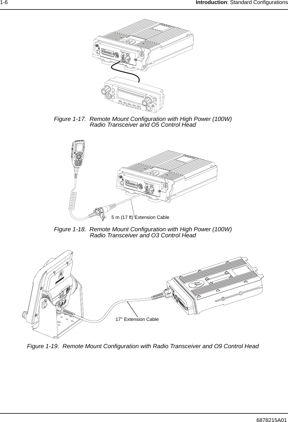
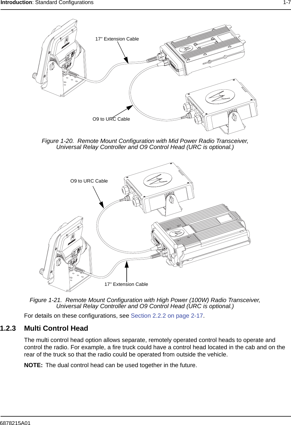
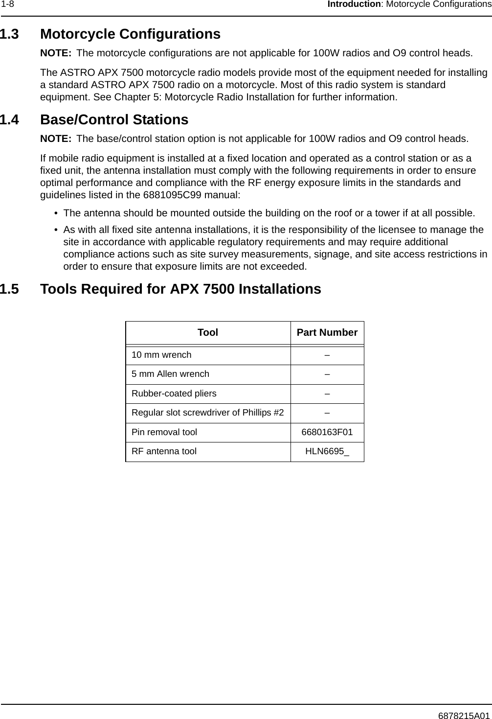
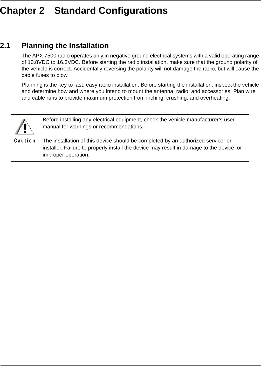
Installation manual
4.
Ex8b RF Safety Guide Amended
Installation manual
Navigation menu
Upload a User Manual
Namespaces
Wiki Guide
HTML
PDF
Info
Views
User Manual
Discussion / Help
Navigation