Motorola Solutions 92FT4904 Mobile Radio User Manual 6878215A01
Motorola Solutions, Inc. Mobile Radio 6878215A01
Contents
- 1. Ex8a Draft Users Manual
- 2. Ex8b RF Safety Booklet
- 3. Installation manual
- 4. Ex8b RF Safety Guide Amended
Installation manual

i
Foreword
This manual covers the O3, O5, and O9 models of the ASTRO® APX™ 7500 digital mobile radios. It includes all the
information necessary to install mid power and high power radios, and configure radio installation inside vehicles.
For details on radio operation or component-level troubleshooting, refer to the applicable manuals available separately. A
list of related publications is provided in the section “Related Publications,” on page vi.
Product Safety and RF Exposure Compliance
See “Installation Requirements for Compliance with Radio Frequency (RF) Energy Exposure Safety Standards,” on page ii.
Manual Revisions
Changes which occur after this manual is printed are described in PMRs (Publication Manual Revisions). These PMRs
provide complete replacement pages for all added, changed, and deleted items.
To obtain PMRs, go to https://businessonline.motorola.com.
Parts Ordering
See Appendix A: Replacement Parts Ordering for information on how to obtain replacement parts. For part numbers, refer
to the ASTRO APX 7500 Digital Mobile Radio Basic Service Manual (Motorola publication part number 6875964M01).
Computer Software Copyrights
The Motorola products described in this manual may include copyrighted Motorola computer programs stored in
semiconductor memories or other media. Laws in the United States and other countries preserve for Motorola certain
exclusive rights for copyrighted computer programs, including, but not limited to, the exclusive right to copy or reproduce in
any form the copyrighted computer program. Accordingly, any copyrighted Motorola computer programs contained in the
Motorola products described in this manual may not be copied, reproduced, modified, reverse-engineered, or distributed in
any manner without the express written permission of Motorola. Furthermore, the purchase of Motorola products shall not
be deemed to grant either directly or by implication, estoppel, or otherwise, any license under the copyrights, patents or
patent applications of Motorola, except for the normal non-exclusive license to use that arises by operation of law in the
sale of a product.
Document Copyrights
No duplication or distribution of this document or any portion thereof shall take place without the express written permission
of Motorola. No part of this manual may be reproduced, distributed, or transmitted in any form or by any means, electronic
or mechanical, for any purpose without the express written permission of Motorola.
Disclaimer
The information in this document is carefully examined, and is believed to be entirely reliable. However, no responsibility is
assumed for inaccuracies. Furthermore, Motorola reserves the right to make changes to any products herein to improve
readability, function, or design. Motorola does not assume any liability arising out of the applications or use of any product
or circuit described herein; nor does it cover any license under its patent rights nor the rights of others.
Trademarks
MOTOROLA, the Stylized M logo, FLASHport, and ASTRO are registered in the US Patent & Trademark Office. All other
product or service names are the property of their respective owners.
© 2009, 2010 by Motorola, Inc.

ii
Installation Requirements for Compliance with
Radio Frequency (RF) Energy Exposure Safety
Standards
ATTENTION!
This radio is intended for use in occupational/controlled conditions, where users have full knowledge
of their exposure and can exercise control over their exposure to meet FCC limits. This radio device is
NOT authorized for general population, consumer, or any other use.
To ensure compliance to RF Energy Safety Standards:
• Install only Motorola approved antennas and accessories
• Be sure that antenna installation is per “Antenna Installation,” on page 2-33 of this manual
• Be sure that Product Safety and RF Safety Booklet enclosed with this radio is available to the end user
upon completion of the installation of this radio
Before using this product, the operator must be familiar with the RF energy awareness information and
operating instructions in the Product Safety and RF Exposure booklet enclosed with each radio (Motorola
Publication part number 6881095C99) to ensure compliance with Radio Frequency (RF) energy exposure
limits.
For a list of Motorola-approved antennas and other accessories, visit the following web site which lists
approved accessories for your radio model: http://www.motorola.com/governmentandenterprise.

Table of Contents iii
6878215A01
Table of Contents
Foreword..........................................................................................................i
Product Safety and RF Exposure Compliance.............................................................................................i
Manual Revisions .........................................................................................................................................i
Parts Ordering ..............................................................................................................................................i
Computer Software Copyrights ....................................................................................................................i
Document Copyrights...................................................................................................................................i
Disclaimer.....................................................................................................................................................i
Trademarks ..................................................................................................................................................i
Installation Requirements for Compliance with
Radio Frequency (RF) Energy Exposure Safety Standards.......................ii
Mobile Radio Model Numbering Scheme....................................................xi
Commercial Warranty.................................................................................xiii
Limited Warranty ...................................................................................................................................... xiii
MOTOROLA COMMUNICATION PRODUCTS.............................................................................. xiii
I. What This Warranty Covers And For How Long ................................................................... xiii
II. General Provisions............................................................................................................... xiii
III. State Law Rights .................................................................................................................xiv
IV. How To Get Warranty Service ............................................................................................xiv
V. What This Warranty Does Not Cover...................................................................................xiv
VI. Patent And Software Provisions ..........................................................................................xv
VII. Governing Law....................................................................................................................xv
Chapter 1 Introduction ......................................................................... 1-1
1.1 Mobile Radio Description............................................................................................................... 1-1
1.1.1 Dimensions ....................................................................................................................... 1-1
1.2 Standard Configurations ................................................................................................................ 1-3
1.2.1 Dash Mount Configuration ................................................................................................ 1-3
1.2.2 Remote Mount Configuration............................................................................................ 1-5
1.2.3 Multi Control Head ............................................................................................................ 1-7
1.3 Motorcycle Configurations ............................................................................................................. 1-8
1.4 Base/Control Stations .................................................................................................................... 1-8
1.5 Tools Required for APX 7500 Installations ....................................................................................1-8
Chapter 2 Standard Configurations.................................................... 2-1
2.1 Planning the Installation................................................................................................................. 2-1
2.1.3 Radio Operation Wiring for Dash and Remote Configurations ....................................... 2-11
2.1.3.1 Dash Mount: Power, Ignition, and Emergency Cable Installation.......................... 2-11
2.1.3.2 Remote Mount: Power, Ignition, and Emergency Cable Installation...................... 2-12
2.1.4 Ignition Sense Switch (Radio Wide Advance) ................................................................ 2-14

iv Table of Contents
6878215A01
2.2 Radio Mounting ........................................................................................................................... 2-15
2.2.2 Remote Mount with Trunnion.......................................................................................... 2-17
2.2.2.1 100W Radios Only................................................................................................. 2-18
2.2.2.2 Remote Mount Control Head Installation............................................................... 2-18
2.2.2.3 Multiple Control Head Installation.......................................................................... 2-22
2.2.2.4 Cable Installation ................................................................................................... 2-23
2.2.2.5 Setting the Initial Control Head ID ......................................................................... 2-24
2.2.2.6 O3 Control Head and Remote Mount Cabling....................................................... 2-25
2.2.3 Locking Kit (Optional) .....................................................................................................2-27
2.2.3.1 All Radios Except 100W........................................................................................ 2-27
2.2.3.2 100W Radios......................................................................................................... 2-27
2.3 Power Cables (Transceiver and Control Head)........................................................................... 2-28
2.3.1 Optional Locking Feature for High Power Chassis Power Cables.................................. 2-28
2.3.2 O5 or O9 Control Head Power Cables ........................................................................... 2-31
2.3.3 Battery Selector Switch................................................................................................... 2-32
2.4 Antenna Installation ..................................................................................................................... 2-33
2.4.1 Selecting an Antenna Site/Location on a Metal Body Vehicle........................................ 2-33
2.4.2 Mini-UHF Connection ..................................................................................................... 2-35
2.4.3 GPS Antenna Placement................................................................................................ 2-37
2.4.4 GPS Connection.............................................................................................................2-37
2.5 Speaker ....................................................................................................................................... 2-38
2.6 Microphone Hang-Up Clip ........................................................................................................... 2-39
2.6.1 Standard or O3 Control Head Hang-Up Clip .................................................................. 2-39
2.7 RFID (Option) .............................................................................................................................. 2-39
2.7.1 RFID Reading................................................................................................................. 2-40
2.7.2 Programming RFID (If Equipped) ................................................................................... 2-42
2.8 Completing the Installation .......................................................................................................... 2-43
Chapter 3 Universal Relay Controller Installation ............................. 3-1
3.1 Universal Relay Controller Mounting ............................................................................................. 3-1
3.2 O9 Universal Relay Controller Cable Assembly ............................................................................ 3-3
3.2.1 Power Cable ..................................................................................................................... 3-3
3.2.2 Ground Cable ................................................................................................................... 3-3
3.2.3 Wires ................................................................................................................................ 3-4
3.2.4 O9 to URC Cable.............................................................................................................. 3-5
Chapter 4 Options and Accessories Installation ............................... 4-1
4.1 Dash-Mount Accessory Installation ............................................................................................... 4-1
4.1.1 Dash-Mount Emergency Pushbutton or Footswitch Installation ....................................... 4-1
4.1.2 Dash-Mount Horn and Lights (External Alarms) Relays................................................... 4-2
4.2 Remote-Mount Accessory Installation ........................................................................................... 4-2
4.2.1 Emergency Pushbutton or Footswitch Installation............................................................ 4-3
4.2.2 Horn (External Alarm) Relay Installation........................................................................... 4-4
4.2.3 Lights (External Alarm) Relay Installation......................................................................... 4-4
4.2.4 Gunlock Installation .......................................................................................................... 4-4
4.2.5 Horn-Ring Transfer........................................................................................................... 4-5
4.2.6 Record Audio Out Jack of Transmit and Receive Audio................................................... 4-5
4.2.7 Earphone Jack.................................................................................................................. 4-5
4.2.8 USB Data Cables.............................................................................................................. 4-6
4.2.9 RS232 Cables .................................................................................................................. 4-6

Table of Contents v
6878215A01
4.3 Vehicle Interface Port Overview .................................................................................................... 4-6
4.3.1 VIP Output Connections ................................................................................................... 4-7
4.3.2 VIP Input Connections ......................................................................................................4-8
4.4 Compatibility of Emergency when Attaching a Siren ..................................................................... 4-9
4.5 Accessory Connector Assembly Details (P2) (All Models Except 100W).................................... 4-10
4.5.1 Disassembly and Assembly............................................................................................ 4-10
4.5.1.1 Disassembly .......................................................................................................... 4-10
4.5.1.2 Assembly ............................................................................................................... 4-11
4.5.2 Adapter Cable................................................................................................................. 4-12
4.6 Memory and Three-Day Secure Key Retention Option ............................................................... 4-12
Chapter 5 Motorcycle Radio Installation ............................................ 5-1
5.1 Motorcycle Radio Description ........................................................................................................ 5-1
5.1.1 Transceiver Enclosure ......................................................................................................5-1
5.1.2 Control/Display Unit .......................................................................................................... 5-1
5.1.3 Control Head Cable .......................................................................................................... 5-2
5.1.4 Microphone ....................................................................................................................... 5-2
5.1.5 Keypad Mic ....................................................................................................................... 5-2
5.1.6 External Speaker .............................................................................................................. 5-2
5.1.7 Headset Capability............................................................................................................ 5-2
5.1.8 Antenna ............................................................................................................................ 5-2
5.1.9 Ignition Sense (ACC) Wire................................................................................................ 5-2
5.2 Installation Overview...................................................................................................................... 5-3
5.2.1 General ............................................................................................................................. 5-3
5.2.2 Important Installation Hints ...............................................................................................5-4
5.2.3 Parts Identification ............................................................................................................ 5-5
5.2.4 Order of Installation .......................................................................................................... 5-5
5.3 Installing the Universal Mounting Plate.......................................................................................... 5-6
5.4 Installing the Speaker and Control Head....................................................................................... 5-7
5.4.1 Handlebar Installation with Speaker and Control Head Mounted Together...................... 5-8
5.4.2 Fuel Tank Console Installation with Speaker and Control Head Mounted Together ........ 5-9
5.4.3 Handlebar Installation with Speaker and Control Head Mounted Separately................. 5-11
5.4.4 Fuel Tank Console Installation with Speaker and Control Head Mounted Separately ... 5-12
5.5 Installing the Speaker .................................................................................................................. 5-14
5.6 Installing the Microphone Hang-Up Clip ...................................................................................... 5-14
5.6.1 Extension Bracket Mounting ........................................................................................... 5-14
5.6.2 Speaker/Control Head Bracket Side Mounting ............................................................... 5-14
5.6.3 Other Hang-Up Clip Mounting ........................................................................................ 5-15
5.7 Installing Antenna Base and Cables............................................................................................ 5-15
5.8 Installing the Antenna .................................................................................................................. 5-18
5.9 Cable Routing.............................................................................................................................. 5-18
5.10 Installing the Weather-Resistant Enclosure................................................................................. 5-20
5.11 Transceiver and Cabling Installation............................................................................................ 5-21
5.11.1 Installing Cabling in the Enclosure.................................................................................. 5-21
5.11.2 Installing the Transceiver................................................................................................5-22
5.12 Installing the Emergency Switch Option ......................................................................................5-24
5.13 Installing the External Alarm Relay Option ..................................................................................5-24
5.14 Installing the Headset Accessory................................................................................................. 5-24
5.15 Installing the Control Head Sunshield.......................................................................................... 5-25
5.16 Horn/Lights Wiring ....................................................................................................................... 5-27
5.17 Emergency Switch Wiring............................................................................................................ 5-27

vi Table of Contents
6878215A01
Chapter 6 Finishing the Installation.................................................... 6-1
6.1 Cable Connection .......................................................................................................................... 6-1
6.1.1 O9 Control Head............................................................................................................... 6-1
6.1.2 O5 Control Head............................................................................................................... 6-1
6.1.3 O3 Control Head............................................................................................................... 6-2
6.2 Dust Cover Installation .................................................................................................................. 6-3
6.3 Miscellaneous Information............................................................................................................. 6-4
Chapter 7 Best Practices: Installation & Troubleshooting ............... 7-1
7.1 Check Wiring of Ignition and Radio Ignition Sensing..................................................................... 7-1
7.2 Check Physical Installation of Radio Ground and Radio Accessory Wiring .................................. 7-2
7.3 Improve the Electrical Quality of the Power and Ignition Lines ..................................................... 7-2
7.4 Minimize the Effect of Poorly Grounded Antennas........................................................................ 7-3
7.5 Jump-Start the Vehicle .................................................................................................................. 7-3
7.6 Eliminate Noise/Howling from PA Speaker ................................................................................... 7-3
Appendix A Replacement Parts Ordering..............................................A-1
A.1 Basic Ordering Information............................................................................................................A-1
A.2 Motorola Online .............................................................................................................................A-1
A.3 Mail Orders ....................................................................................................................................A-1
A.5 Fax Orders.....................................................................................................................................A-2
A.6 Parts Identification .........................................................................................................................A-2
A.7 Product Customer Service.............................................................................................................A-2
Index.....................................................................................................Index-1
Glossary.........................................................................................Glossary-1
Related Publications
ASTRO APX 7500 Digital Mobile Radio O3 Control Head User Guide ..................................... 6875946M01
ASTRO APX 7500 Digital Mobile Radio O5 Control Head User Guide ..................................... 6875947M01
ASTRO APX 7500 Digital Mobile Radio O9 Control Head User Guide .................................... 68007024014
ASTRO APX 7500 Digital Mobile Radio Basic Service Manual ................................................. 6875964M01
ASTRO APX 7500 Digital Mobile Radio Detailed Service Manual ............................................ 6875963M01

List of Figures vii
6878215A01
List of Figures
Figure 1-1. Front View of Mid Power Dash Mount Transceiver and Trunnion......................................... 1-1
Figure 1-2. Side View of Mid Power Dash Mount Transceiver and Trunnion.......................................... 1-1
Figure 1-3. Front View of High Power (100W) Transceiver and Trunnion............................................... 1-1
Figure 1-4. Side View of High Power (100W) Transceiver and Trunnion................................................ 1-1
Figure 1-5. Front View of O3 Control Head with Coiled Cable................................................................ 1-2
Figure 1-6. Side View of O3 Control Head with Coiled Cable................................................................. 1-2
Figure 1-7. Front View of O5 Control Head with Trunnion ...................................................................... 1-2
Figure 1-8. Side View of O5 Control Head with Trunnion........................................................................ 1-2
Figure 1-9. Front View of O9 Control Head with Trunnion ...................................................................... 1-2
Figure 1-10. Side View of O9 Control Head with Trunnion........................................................................ 1-2
Figure 1-11. Top View of O9 Universal Relay Controller with Trunnion
(URC is an orderable accessory.)......................................................................................... 1-3
Figure 1-12. Side View of O9 Universal Relay Controller with Trunnion
(URC is an orderable accessory.)......................................................................................... 1-3
Figure 1-13. Dash Mount Configuration with O5 Control Head................................................................. 1-3
Figure 1-14. Dash Mount Configuration with Transceiver Interface Board and O3 Control Head ............ 1-4
Figure 1-15. Remote Mount Configuration with Mid Power Transceiver and O5 Control Head................ 1-5
Figure 1-16. Remote Mount Configuration with Mid Power Transceiver, Transceiver Interface Board,
and O3 Control Head............................................................................................................ 1-5
Figure 1-17. Remote Mount Configuration with High Power (100W) Radio Transceiver
and O5 Control Head............................................................................................................ 1-6
Figure 1-18. Remote Mount Configuration with High Power (100W) Radio Transceiver
and O3 Control Head............................................................................................................ 1-6
Figure 1-19. Remote Mount Configuration with Radio Transceiver and O9 Control Head ....................... 1-6
Figure 1-20. Remote Mount Configuration with Mid Power Radio Transceiver,
Universal Relay Controller and O9 Control Head (URC is optional.).................................... 1-7
Figure 1-21. Remote Mount Configuration with High Power (100W) Radio Transceiver,
Universal Relay Controller and O9 Control Head (URC is optional.).................................... 1-7
Figure 2-1. Dash Mount Radios Can Be Located in the Middle Console, on the Transmission Hump,
or Under the Dash (See Figure 2-2 for 100W Radio Install)................................................. 2-2
Figure 2-2. Remote Mount Radio Control Heads Can Be Located in the Middle Console,
on the Transmission Hump, or Under the Dash.................................................................... 2-2
Figure 2-3. Remote Mount of the Radio, O9 Control Head, and Universal Relay Controller
(URC is optional.).................................................................................................................. 2-2
Figure 2-4. Radio Installation (O5 Mid Power Dash Mount).................................................................... 2-3
Figure 2-5. Radio Installation (O3 Mid Power Dash Mount).................................................................... 2-4
Figure 2-6. Radio Installation (O5 Mid Power Remote Mount)................................................................ 2-4
Figure 2-7. Radio Installation (O3 Mid Power Remote Mount)................................................................ 2-5
Figure 2-8. Radio Installation (O3 High Power Remote Mount) .............................................................. 2-5
Figure 2-9. Radio Installation (O5 High Power Remote Mount) .............................................................. 2-6
Figure 2-10. Radio Installation of O9 Remote Mount with Transceiver (URC is optional.)........................ 2-6
Figure 2-11. Radio Installation (O9 Remote Mount with Pinouts) ............................................................. 2-7
Figure 2-12. Remote Control Head Pinouts .............................................................................................. 2-7
Figure 2-13. Cabling Interconnect Diagram for Dash Mount (Cannot Be Used for 100W Radios) ........... 2-8
Figure 2-14. Cabling Interconnect Diagram for Remote Mount................................................................. 2-9
Figure 2-15. Cabling Interconnect Diagram for 09 Remote Mount (URC is optional.) ............................ 2-10
Figure 2-16. Trunnion Orientation (Cannot Be Used for 100W Radios).................................................. 2-15
Figure 2-17. Trunnion Orientation for 100W Radios................................................................................2-15
Figure 2-18. Transmission Hump Trunnion Mounting ............................................................................. 2-16
Figure 2-19. Below Dash Trunnion Mounting.......................................................................................... 2-17

viii List of Figures
6878215A01
Figure 2-20. 100W Radio Mounting into Quick Release Trunnion.......................................................... 2-18
Figure 2-21. O5 Control Head Installation Exploded View...................................................................... 2-19
Figure 2-22. O9 Control Head Installation Exploded View...................................................................... 2-20
Figure 2-23. O5 Control Head Rear View ............................................................................................... 2-20
Figure 2-24. O9 Control Head Rear View ............................................................................................... 2-21
Figure 2-25. Multiple Control Heads Example Configurations ................................................................ 2-22
Figure 2-26. APX 7500 Front View ......................................................................................................... 2-24
Figure 2-27. Radio Display with Current Control Head ID ...................................................................... 2-24
Figure 2-28. APX 7500 Front View – Mode Knob................................................................................... 2-24
Figure 2-29. O3 Control Head................................................................................................................. 2-25
Figure 2-30. O3 Control Head Rear View ............................................................................................... 2-26
Figure 2-31. Hang-Up Clip Installation Exploded View ........................................................................... 2-26
Figure 2-32. Locking Kit (Optional) (Cannot Be Used for 100W Radios)................................................ 2-27
Figure 2-33. Lock Supplied with 100W Quick Release Trunnion............................................................ 2-27
Figure 2-34. Bracket Installation ............................................................................................................. 2-28
Figure 2-35. Bracket Installation ............................................................................................................. 2-29
Figure 2-36. Bracket Installation (Assembled State) ............................................................................... 2-29
Figure 2-37. Bracket Uninstallation......................................................................................................... 2-30
Figure 2-38. Bracket Uninstallation......................................................................................................... 2-30
Figure 2-39. HKN6188_ Power Cable with External Speaker Connector ............................................... 2-31
Figure 2-40. HKN6187_ Power Cable with External Speaker Connector,
Record Audio Output Jack (2.5 mm) and Earphone Jack (2.5 mm)................................... 2-31
Figure 2-41. Battery Selector Switch....................................................................................................... 2-32
Figure 2-42. Multiple Antennas Separation............................................................................................. 2-34
Figure 2-43. Mini-UHF Connection (As Shown on Mid Power)............................................................... 2-35
Figure 2-44. Mini-UHF Connection (100W Radios Only)........................................................................ 2-35
Figure 2-45. Mini-UHF Connector Tool (As Shown on Mid Power)......................................................... 2-36
Figure 2-46. Mini-UHF Connector Tool (100W Radios Only) .................................................................. 2-36
Figure 2-47. GPS Antenna Connector on the Back of the Mid Power Radio.......................................... 2-37
Figure 2-48. GPS Antenna Connector on the Front of the 100W Radio................................................. 2-37
Figure 2-49. Speaker Mounting............................................................................................................... 2-38
Figure 2-50. RFID Location on Mid Power Radio ................................................................................... 2-39
Figure 2-51. RFID Location on High Power Radio.................................................................................. 2-39
Figure 2-52. Read Angle for Mid Power Radio ....................................................................................... 2-40
Figure 2-53. Tag Angle for Mid Power Radio .......................................................................................... 2-40
Figure 2-54. Read Angle for High Power Radio...................................................................................... 2-41
Figure 2-55. Tag Angle for High Power Radio......................................................................................... 2-41
Figure 2-56. Examples of Reader and Tag Aligned (Reader Orientation)............................................... 2-41
Figure 2-57. Example of Reader and Tag Misaligned (Reader Orientation) ........................................... 2-42
Figure 3-1. Universal Relay Controller Orientation ................................................................................. 3-1
Figure 3-2. Universal Relay Controller Installation Exploded View ......................................................... 3-2
Figure 3-3. Power and Ground Cable Glands......................................................................................... 3-3
Figure 3-4. Cable Gland Assembly with Gasket .....................................................................................3-4
Figure 3-5. Wires Installation .................................................................................................................. 3-4
Figure 3-6. Wire Installation with Black Stick .......................................................................................... 3-5
Figure 3-7. O9 to URC Cable Installation................................................................................................ 3-5
Figure 4-1. Emergency Switch Wiring Diagram ......................................................................................4-1
Figure 4-2. Horn/Light Wiring Diagram ................................................................................................... 4-2
Figure 4-3. Emergency Jumper Removal in Remote Mount................................................................... 4-3
Figure 4-4. Gunlock Switch Redundancy Diagram ................................................................................. 4-4
Figure 4-5. Siren/PA Horn-Ring Connections ......................................................................................... 4-5
Figure 4-6. Remote Control Head Pinouts .............................................................................................. 4-6
Figure 4-7. HKN6196_ VIP Connector Detail.......................................................................................... 4-6
Figure 4-8. Relay Coil ............................................................................................................................. 4-7

List of Figures ix
6878215A01
Figure 4-9. Field adjustment for Emergency Operation with Siren Accessory........................................ 4-9
Figure 4-10. Location for Pin 8.................................................................................................................. 4-9
Figure 4-11. Exploded View of Accessory Connector Assembly (HLN6863_)........................................ 4-11
Figure 4-12. Rear Accessory Connector Audio Configuration ................................................................ 4-12
Figure 4-13. Rear Accessory Connector Data Configuration.................................................................. 4-12
Figure 5-1. Identification of a Motorcycle Radio by Using a Label .......................................................... 5-1
Figure 5-2. Universal Mounting Plate Installation (Part of Radio Enclosure Kit) ..................................... 5-6
Figure 5-3. Motorcycle Control Head Cabling (3075217A01) ................................................................. 5-7
Figure 5-4. Handlebar Installation with Speaker and Control Head Mounted Together .......................... 5-8
Figure 5-5. Fuel Tank Console Installation with Speaker and Control Head Mounted Together ........... 5-10
Figure 5-6. Handlebar Installation with Speaker and Control Head Mounted Separately ..................... 5-12
Figure 5-7. Fuel Tank Console Installation with Speaker and Control Head Mounted Separately........ 5-13
Figure 5-8. Location of Band 1 or Band 2 (Depending on the Antenna Port They Align to).................. 5-15
Figure 5-9. Antenna Band Identification................................................................................................ 5-16
Figure 5-10. Routing the Coaxial Cable for GPS .................................................................................... 5-16
Figure 5-11. Routing the Coaxial Cable for Band 1................................................................................. 5-17
Figure 5-12. Routing the Coaxial Cable for Band 2................................................................................. 5-17
Figure 5-13. Cable Routing ..................................................................................................................... 5-18
Figure 5-14. Weather-Resistant Enclosure Installation ........................................................................... 5-20
Figure 5-15. Installing Cables.................................................................................................................. 5-22
Figure 5-16. Installing the Transceiver .................................................................................................... 5-23
Figure 5-17. Motorcycle Wiring Harness Rework....................................................................................5-24
Figure 5-18. Remote Mount Trunnion with Sunshield ............................................................................. 5-25
Figure 5-19. Position the Sunshield ........................................................................................................ 5-25
Figure 5-20. Slide the Control Head onto Trunnion................................................................................. 5-26
Figure 5-21. Position Control Head as Desired....................................................................................... 5-26
Figure 5-22. Horn/Lights Wiring Diagram................................................................................................ 5-27
Figure 5-23. Emergency Switch Wiring Diagram .................................................................................... 5-27
Figure 6-1. Dust Cover Installation Locations ......................................................................................... 6-3

xList of Tables
6878215A01
List of Tables
Table 2-1. Dash O5 Radio Operations Dependent Upon A+ and Ignition Connections............ 2-13
Table 2-2. Remote O5 or O9 Radio Operations Dependent Upon A+
and Ignition Connections.......................................................................................... 2-13
Table 2-3. Remote O5 or O9 Radio Operations Dependent Upon A+
and Ignition Connections.......................................................................................... 2-13
Table 2-4. Ignition Sense Switch Settings in CPS..................................................................... 2-14
Table 2-5. Available CAN Cables.............................................................................................. 2-23
Table 2-6. Ignition Interface Cables .......................................................................................... 2-23
Table 2-7. Power Cables........................................................................................................... 2-28
Table 2-8. Model Number Chart in 12-Digit ASCII Format........................................................ 2-42
Table 2-9. Serial Number with Radio Band/Tier/Power............................................................. 2-42
Table 4-1. VIP Output Connections ............................................................................................ 4-7
Table 4-2. VIP Input Connections ............................................................................................... 4-8
Table 5-1. Transceiver Installation Parts List ............................................................................ 5-23

6878215A01
Mobile Radio Model Numbering Scheme xi
Mobile Radio Model Numbering Scheme
Position 1 - Type of Unit
M = Mobile
L = Table Top Station
Positions 2 & 3 - Model Series
Position 4 - Frequency Band
Less than 29.7 MHz
29.7 to 35.99 MHz
36 to 41 MHz
42 to 50 MHz
300 to 345 MHz
66 to 80 MHz
74 to 90 MHz
Product Specific
VHF Range
136 to 162 MHz
146 to 178 MHz
174 to 210 MHz
190 to 235 MHz
330 to 370 MHz
366 to 410 MHz
403 to 437 MHz
438 to 482 MHz
470 to 620 MHz
Position 5 - Power Level
0 to 0.7 Watts
0.7 to 0.9 Watts
1.0 to 3.9 Watts
4.0 to 5.0 Watts
5.1 to 6.0 Watts
6.1 to 10 Watts
10.1 to 15 Watts
16 to 25 Watts
26 to 35 Watts
36 to 60 Watts
61 to 110 Watts
Up to 125 Watts
Position 6 - Physical Packages
RF Modem Operation
Receiver Only
Standard Control; No Display
Standard Control; With Display
Limited Keypad; No Display
Limited Keypad; With Display
Full Keypad; No Display
Full Keypad; With Display
Limited Controls; No Display
Limited Controls; Basic Display
Limited Controls; Limited Display
Rotary Controls; Standard Display
Enhanced Controls; Enhanced Display
Low Profile; No Display
Low Profile; Basic Display
Low Profile; Basic Display, Full Keypad
VDV Control Head
Control Head #2
Position 7 - Channel Spacing
0 =
1 = 5KHz
2 = 6.25KHz
3 = 10KHz
4 = 12.5KHz
5 = 15 KHz
6 = 20/25 KHz
7 = 30 KHz
8 = 12.5/25 KHz
9 = Variable/Programmable
Typical Model Number:
Position:
Position 8 - Primary Operation
Conventional/Simplex
Conventional/Duplex
Trunked Twin Type
Dual Mode Trunked
Dual Mode Trunked/Duplex
Trunked Type I
Trunked Type II
FDMA* Digital Dual Mode
TDMA** Digital Dual Mode
Single Sideband
Global Positioning Satellite Capable
Amplitude Companded Sideband (ACSB)
* FDMA = Frequency Division Multiple Access
** TDMA = Time Division Multiple Access
Position 9 - Primary System Type
Conventional
Privacy Plus
Clear SMARTNET
Advanced Conventional Stat-Alert
Enhanced Privacy Plus
Nauganet 888 Series
JSMR* Trunking
Multi-Channel Access
(MCA) Trunking
CoveragePLUS
MPT1327** - Public
MPT1327** - Private
Radiocom
Tone Signalling
* JSMR = Japan Specialized Mobile Radio
** MPT = Ministry of Posts and Telecommunications
Position 10 - Feature Level
0 =
1 = Basic
2 = Limited Package
3 = Limited Plus
4 = Intermediate
5 = Standard Package
6 = Standard Plus
7 = Expanded Package
8 = Expanded Plus
9 = Full Feature/
Programmable
Position 11 - Version
Version Letter (Alpha) - Major Change
Position 12 -
Unique Model Variations
Positions 13 - 16
SP Model Suffix
123 4 56 7 8 910111213141516
M30 U RS 9 P W 1 A N S P 0 1
30 = APX 7500
A
B
C
D
E
F
G
H
J
K
L
M
N
P
Q
R
S
=
=
=
=
=
=
=
=
=
=
=
=
=
=
=
=
=
Product Specific
UHF Range
806 to 870 MHz
825 to 870 MHz
896 to 941 MHz
403 to 470 MHz
1.0 to 1.6 GHz
1.5 to 2.0 GHz
450 to 527 MHz
136 to 174 MHz
T
U
V
W
X
Y
Z
1
2
3
4
5
6
7
8
9
=
=
=
=
=
=
=
=
=
=
=
=
=
=
=
=
A
B
C
D
E
F
G
H
J
K
L
M
=
=
=
=
=
=
=
=
=
=
=
=
1 to 25 Watts
25 to 40 Watts
25 to 45 Watts
10 to 35 Watts
Programmable
N
P
Q
R
S
T
V
W
X
Y
Z
=
=
=
=
=
=
=
=
=
=
=
A
B
C
D
E
F
G
H
J
K
L
M
N
P
Q
R
S
T
U
V
W
X
Y
Z
=
=
=
=
=
=
=
=
=
=
=
=
=
=
=
=
=
=
=
=
=
=
=
=
A
B
C
D
E
F
G
H
J
K
L
M
=
=
=
=
=
=
=
=
=
=
=
=
A
B
C
D
E
F
G
H
J
K
L
M
N
=
=
=
=
=
=
=
=
=
=
=
=
=
A
B
C
D
E
F
G
H
J
K
L
M
=
=
=
=
=
=
=
=
=
=
=
=
* For APX 7500 "U" in Position 4 represents
764 to 870 MHz.
Note: Values represented are not absolute,
and are given to indicate range only.
Note: Values represented are not absolute,
and are given to indicate range only.
N
P
Q
R
S
T
U
V
W
X
Y
Z
=
=
=
=
=
=
=
=
=
=
=
=
Digital Dispatch
Programmable
Digital Interconnect
Digital Multi-Service
TDMA
P
Q
R
S
T
U
V
W
X
Y
Z
2
=
=
=
=
=
=
=
=
=
=
=
=
N
P
Q
R
S
T
U
V
W
X
Y
Z
=
=
=
=
=
=
=
=
=
=
=
=
Binary Signalling
Phonenet
IDEN Basic
IDEN Advanced Feature
JSMR Digital
LTR Protocol
Single Sideband
Programmable
Secure Conventional
Secure SMARTNET
Trans European Trunked
Radio (TETRA)
SmartZone
Cenelec
Standard Package
Chapter 1 Introduction
This manual covers the installation procedures for ASTRO APX 7500 mobile and motorcycle radios
with O3, O5 and O9 control heads, and accessories required to complete the radio system. The
radio system consists of a control head, radio, antenna, microphone, speaker, cabling, Universal
Relay Controller (URC), and accessories.
1.1 Mobile Radio Description
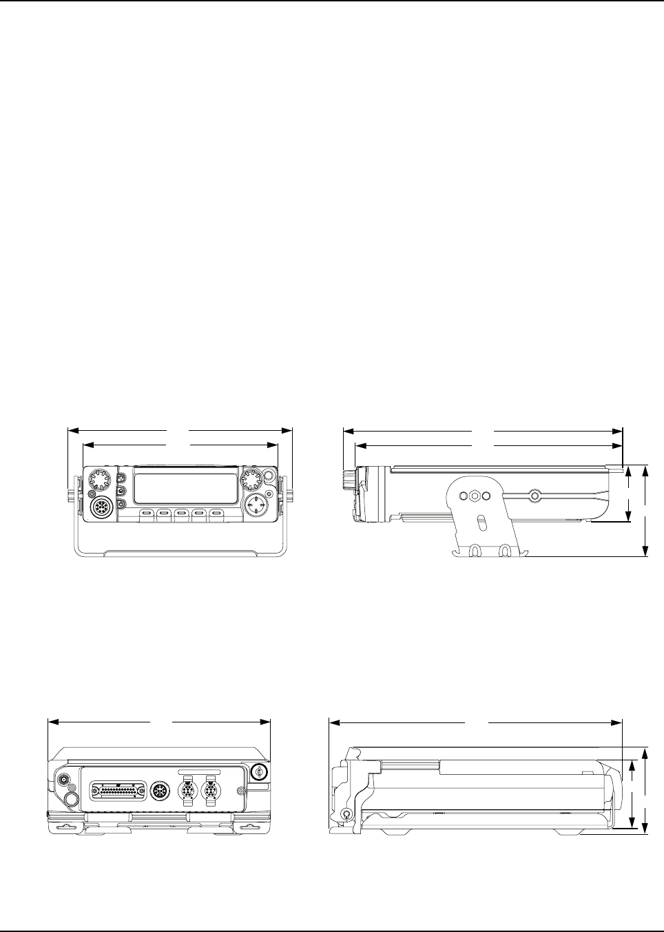
1.1.1 Dimensions
Figure 1-1 and Figure 1-2 show the basic dimensions of the dash mount transceiver trunnion
APX 7500 radio. The transceiver portion of a remote mount APX 7500 is sized similarly.
When installing the radio, make sure to plan the installation carefully and leave additional room in the
rear of the radio for cabling and accessory connections; in the front of the radio for access, controls,
and cabling (if remote mount); and to the sides of the radio so that you may access and install the
trunnion screws/wing screws.
NOTE: The measurement unit used in Figure 1-1 to Figure 1-12 is millimeter.
NOTE: The rear accessory connector adds 0.75 in to the overall length. The remote mount length
is 244 mm.
Figure 1-1. Front View of Mid Power
Dash Mount Transceiver and Trunnion Figure 1-2. Side View of Mid Power
Dash Mount Transceiver and Trunnion
Figure 1-3. Front View of High Power
(100W) Transceiver and Trunnion Figure 1-4. Side View of High Power
(100W) Transceiver and Trunnion
206
180
256
244
51
83
223
74
90
293
6878215A01
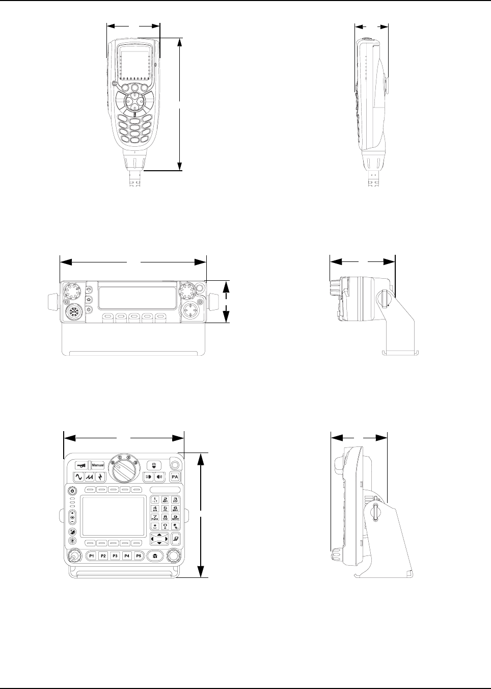
1-2 Introduction: Mobile Radio Description
Figure 1-5. Front View of O3 Control
Head with Coiled Cable Figure 1-6. Side View of O3 Control
Head with Coiled Cable
Figure 1-7. Front View of O5 Control
Head with Trunnion Figure 1-8. Side View of O5 Control
Head with Trunnion
Figure 1-9. Front View of O9 Control
Head with Trunnion Figure 1-10. Side View of O9 Control
Head with Trunnion
61
153
38
51
180 75
178
190 83
6878215A01
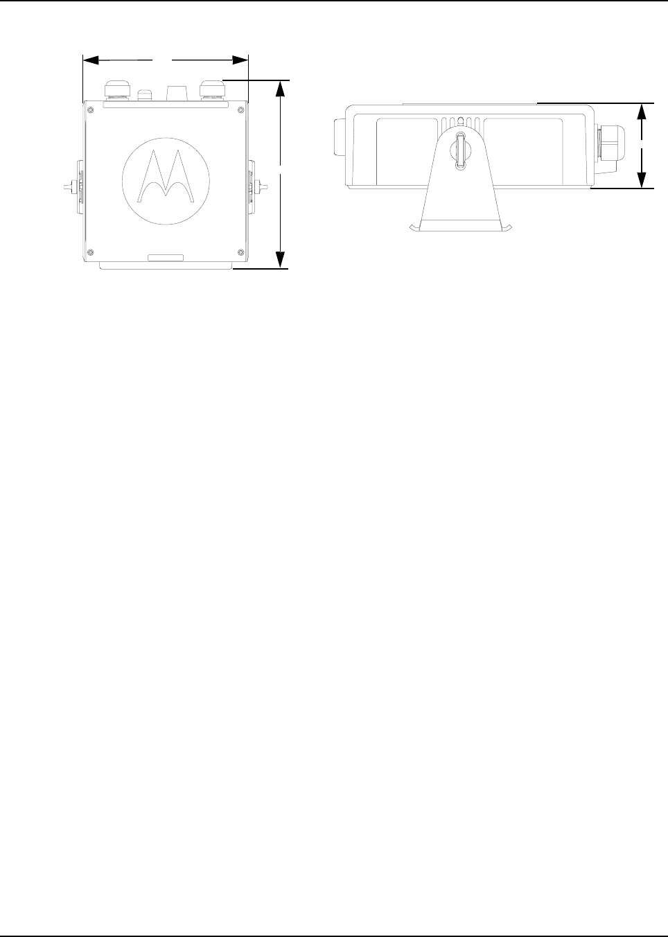
Introduction: Mobile Radio Description 1-3
Figure 1-11. Top View of O9 Universal
Relay Controller with Trunnion
(URC is an orderable accessory.)
Figure 1-12. Side View of O9 Universal
Relay Controller with Trunnion
(URC is an orderable accessory.)
185
210
61.5
6878215A01
1-4 Introduction: Standard Configurations
1.2 Standard Configurations
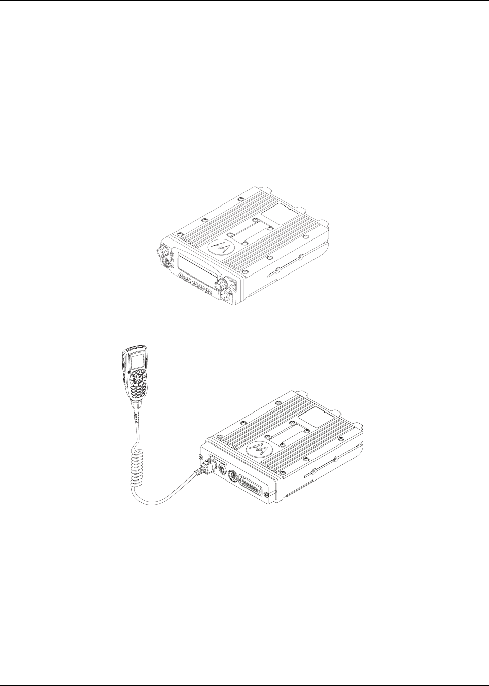
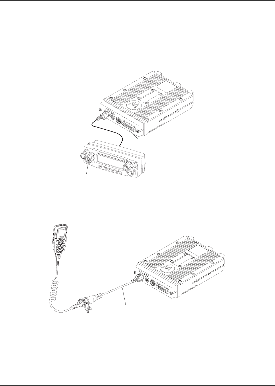
1.2.1 Dash Mount Configuration
NOTE: The dash mount configuration is not applicable for 100W radios and O9 control heads.
There are two versions of the APX 7500 dash mount. The first is the O5 control head which is
mounted on the front of the transceiver housing. The second is the O3 control head which is
connected to the transceiver via a coiled cable, which is plugged into the CAN connector on the
transceiver.
Electrical connection between the two takes place within the radio via a flexible circuit board
between the connectors on the front of the transceiver and at the back of the control head for the O5
and between the connectors on the front of the transceiver and at the back of the TIB for the O3.
Figure 1-13. Dash Mount Configuration with O5 Control Head
Figure 1-14. Dash Mount Configuration with Transceiver Interface Board and
O3 Control Head
For details on this configuration, see Section 2.2.1 on page 2-16.
6878215A01
Introduction: Standard Configurations 1-5
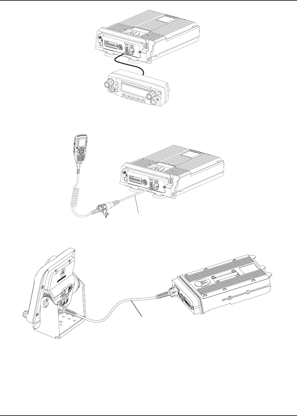
1.2.2 Remote Mount Configuration
In the remote control version, the transceiver and the control head are mounted separately in the
vehicle. The O5 control head is mounted in a remote trunnion near the operator, and the O3 and O9
control heads are also mounted near the operator using an extension cable. The transceiver and
control head are mounted by means of a trunnion or other mounting hardware. If the transceiver is
located in a car trunk, be sure that secure mounting and sufficient cooling are provided. Do not cover
the transceiver with baggage, blankets, etc.
Figure 1-15. Remote Mount Configuration with Mid Power Transceiver and
O5 Control Head
NOTE: The keypad mic should only be plugged into the Modified Modular Plug (MMP) connector
located on the control head, in either dash mount or remote mount configuration.
Figure 1-16. Remote Mount Configuration with Mid Power Transceiver,
Transceiver Interface Board, and O3 Control Head
MMP
MMP
5 m (17 ft) Extension Cable
6878215A01
1-6 Introduction: Standard Configurations
Figure 1-17. Remote Mount Configuration with High Power (100W)
Radio Transceiver and O5 Control Head
Figure 1-18. Remote Mount Configuration with High Power (100W)
Radio Transceiver and O3 Control Head
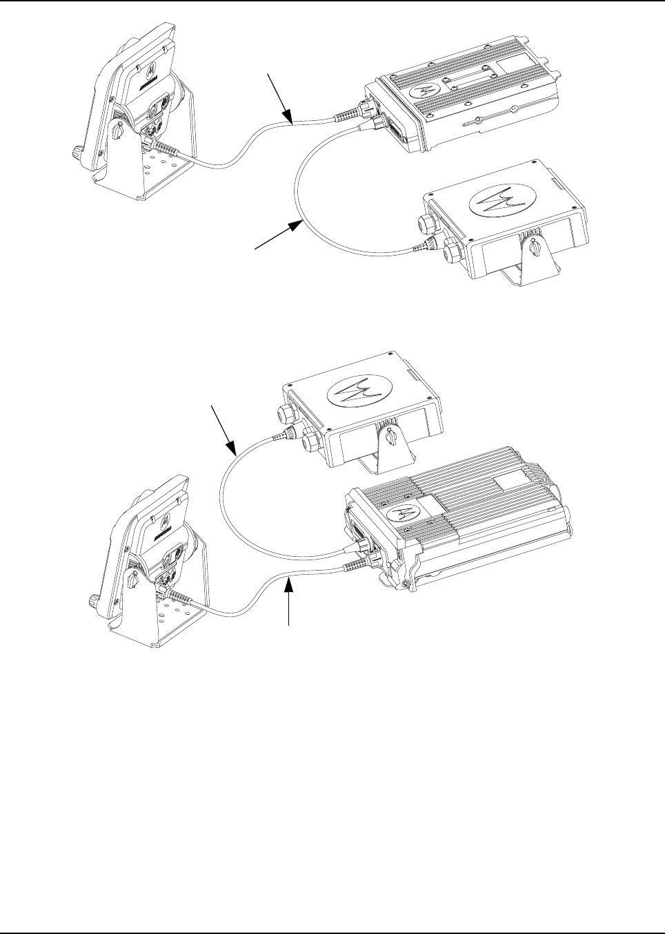
Figure 1-19. Remote Mount Configuration with Radio Transceiver and O9 Control Head
5 m (17 ft) Extension Cable
17'' Extension Cable
6878215A01
Introduction: Standard Configurations 1-7
Figure 1-20. Remote Mount Configuration with Mid Power Radio Transceiver,
Universal Relay Controller and O9 Control Head (URC is optional.)
Figure 1-21. Remote Mount Configuration with High Power (100W) Radio Transceiver,
Universal Relay Controller and O9 Control Head (URC is optional.)
For details on these configurations, see Section 2.2.2 on page 2-17.
1.2.3 Multi Control Head
The multi control head option allows separate, remotely operated control heads to operate and
control the radio. For example, a fire truck could have a control head located in the cab and on the
rear of the truck so that the radio could be operated from outside the vehicle.
NOTE: The dual control head can be used together in the future.
O9 to URC Cable
17'' Extension Cable
O9 to URC Cable
17'' Extension Cable

6878215A01
1-8 Introduction: Motorcycle Configurations
1.3 Motorcycle Configurations
NOTE: The motorcycle configurations are not applicable for 100W radios and O9 control heads.
The ASTRO APX 7500 motorcycle radio models provide most of the equipment needed for installing
a standard ASTRO APX 7500 radio on a motorcycle. Most of this radio system is standard
equipment. See Chapter 5: Motorcycle Radio Installation for further information.
1.4 Base/Control Stations
NOTE: The base/control station option is not applicable for 100W radios and O9 control heads.
If mobile radio equipment is installed at a fixed location and operated as a control station or as a
fixed unit, the antenna installation must comply with the following requirements in order to ensure
optimal performance and compliance with the RF energy exposure limits in the standards and
guidelines listed in the 6881095C99 manual:
• The antenna should be mounted outside the building on the roof or a tower if at all possible.
• As with all fixed site antenna installations, it is the responsibility of the licensee to manage the
site in accordance with applicable regulatory requirements and may require additional
compliance actions such as site survey measurements, signage, and site access restrictions in
order to ensure that exposure limits are not exceeded.
1.5 Tools Required for APX 7500 Installations
Tool Part Number
10 mm wrench –
5 mm Allen wrench –
Rubber-coated pliers –
Regular slot screwdriver of Phillips #2 –
Pin removal tool 6680163F01
RF antenna tool HLN6695_

Chapter 2 Standard Configurations
2.1 Planning the Installation
The APX 7500 radio operates only in negative ground electrical systems with a valid operating range
of 10.8VDC to 16.3VDC. Before starting the radio installation, make sure that the ground polarity of
the vehicle is correct. Accidentally reversing the polarity will not damage the radio, but will cause the
cable fuses to blow.
Planning is the key to fast, easy radio installation. Before starting the installation, inspect the vehicle
and determine how and where you intend to mount the antenna, radio, and accessories. Plan wire
and cable runs to provide maximum protection from inching, crushing, and overheating.
Before installing any electrical equipment, check the vehicle manufacturer’s user
manual for warnings or recommendations.
The installation of this device should be completed by an authorized servicer or
installer. Failure to properly install the device may result in damage to the device, or
improper operation.
!
C a u t i o n
6878215A01
2-2 Standard Configurations: Planning the Installation
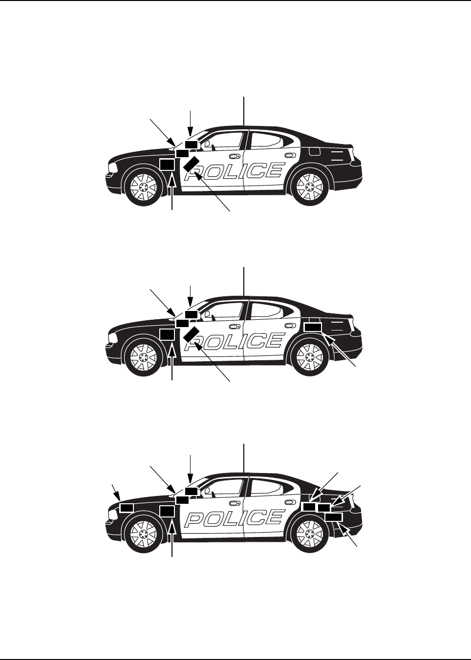
2.1.1 Installation Examples
The mobile two-way radio offers various methods of installation, with accessories placed to the
vehicle as desired. The radio can be a dash or remote mount except for the 100W radio or with 09
control head, which can only be mounted remotely. The O9 control head with the radio and the URC
can only be mounted remotely (see Figure 2-3).
Figure 2-1. Dash Mount Radios Can Be Located in the Middle Console, on the
Transmission Hump, or Under the Dash (See Figure 2-2 for 100W Radio Install)
Figure 2-2. Remote Mount Radio Control Heads Can Be Located in the Middle
Console, on the Transmission Hump, or Under the Dash
Figure 2-3. Remote Mount of the Radio, O9 Control Head,
and Universal Relay Controller (URC is optional.)
NOTE: 100W radio install is typically at the rear vehicle compartment.
911
Antenna
1/4-Wavelength
Radio
Speaker
Battery Radio
911
Antenna
1/4-Wavelength
Control
Head
Speaker
Battery Control
Head
Radio
911
Antenna
1/4-Wavelength
Control Head
Speaker
Battery
Universal Relay
Controller Box
Radio
Siren Speaker Siren Box