Motorola Solutions 92FT4915 Mobile 2-Way Radio User Manual Installation Manual 1 of 2
Motorola Solutions, Inc. Mobile 2-Way Radio Installation Manual 1 of 2
Contents
- 1. Ex8a RF Safety Guide
- 2. Ex8b User Manual
- 3. Installation Manual 1 of 2
- 4. Installation Manual 2of 2
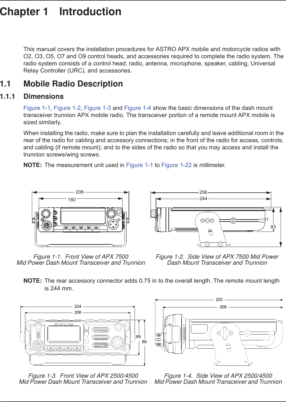
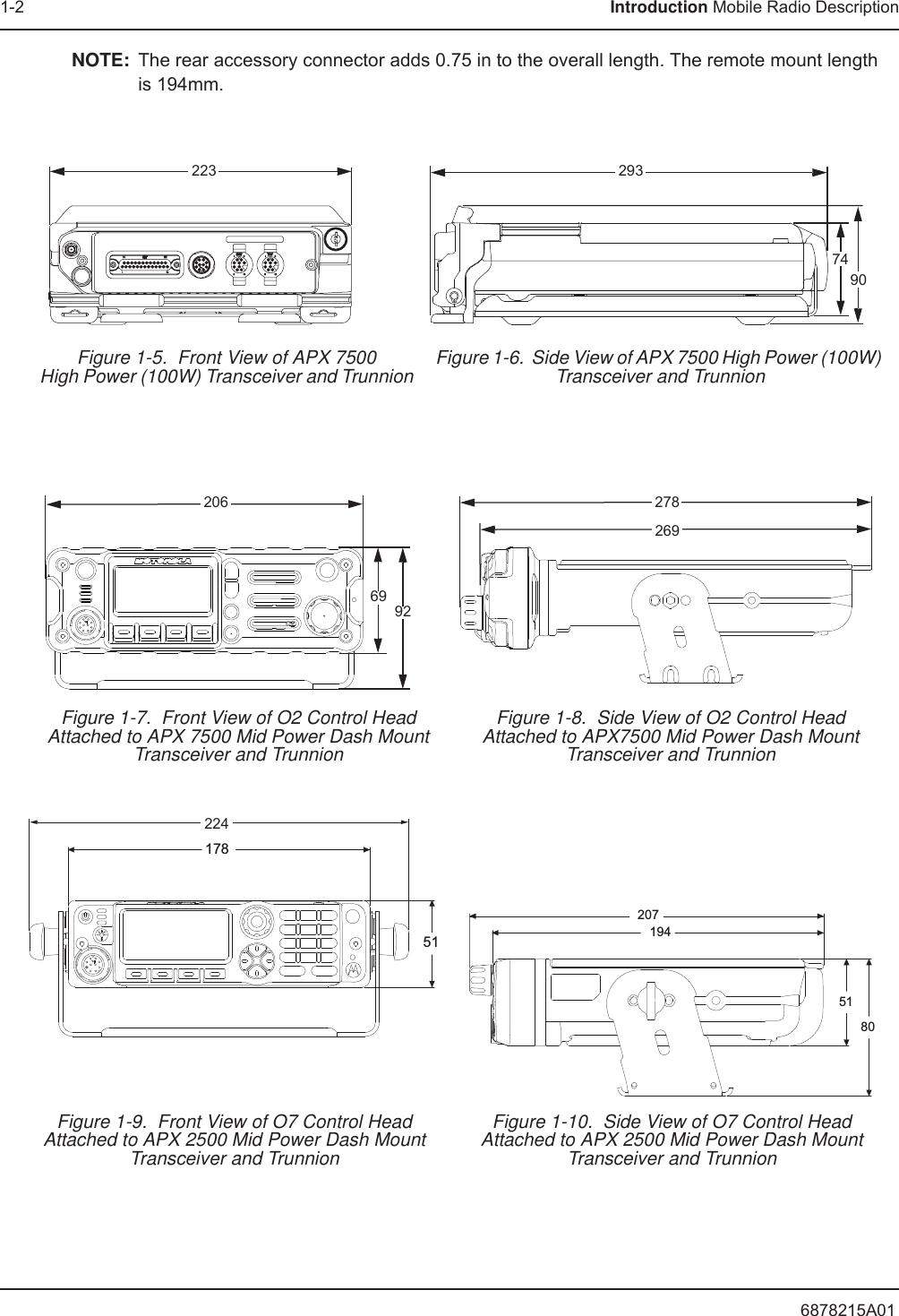
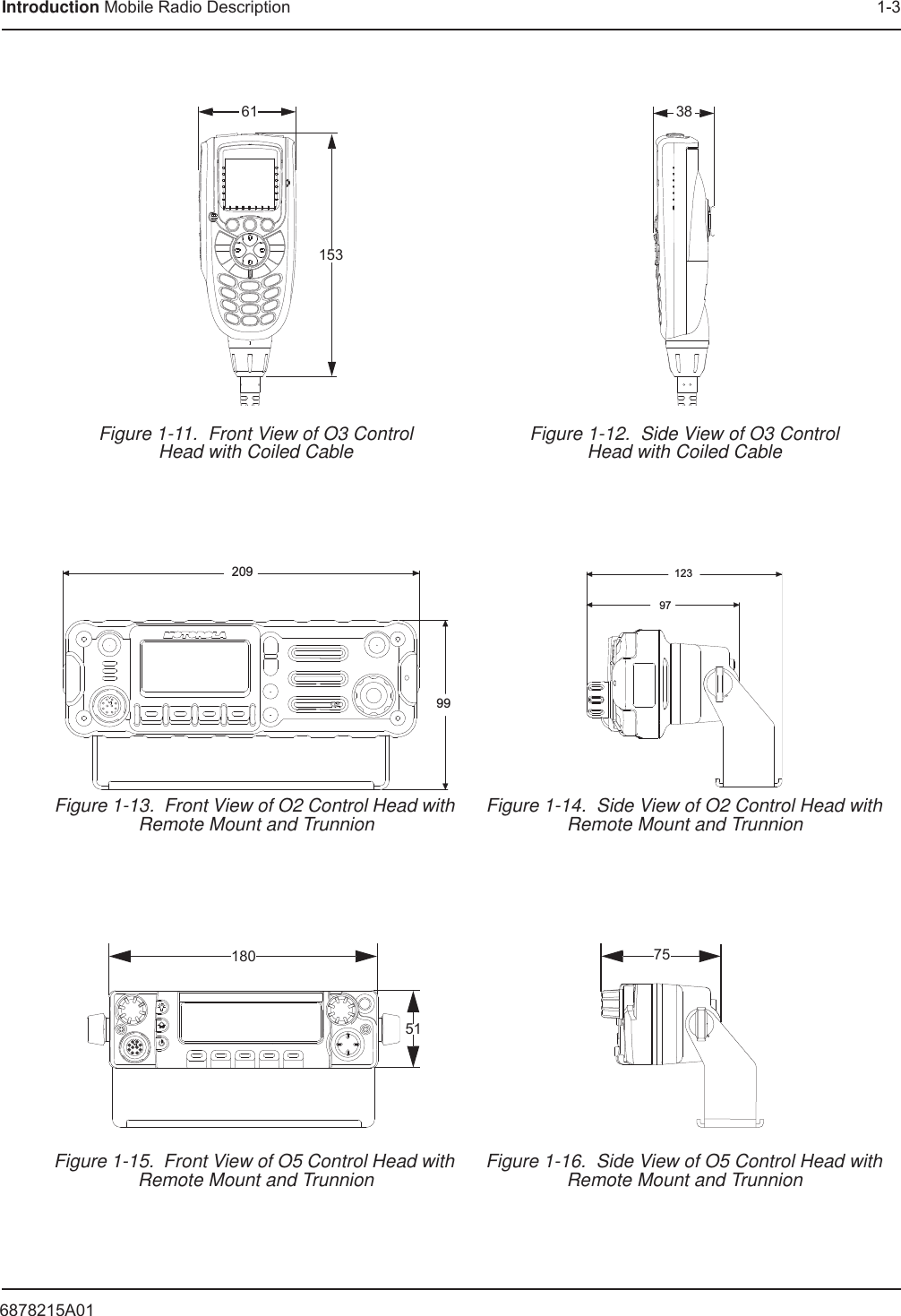
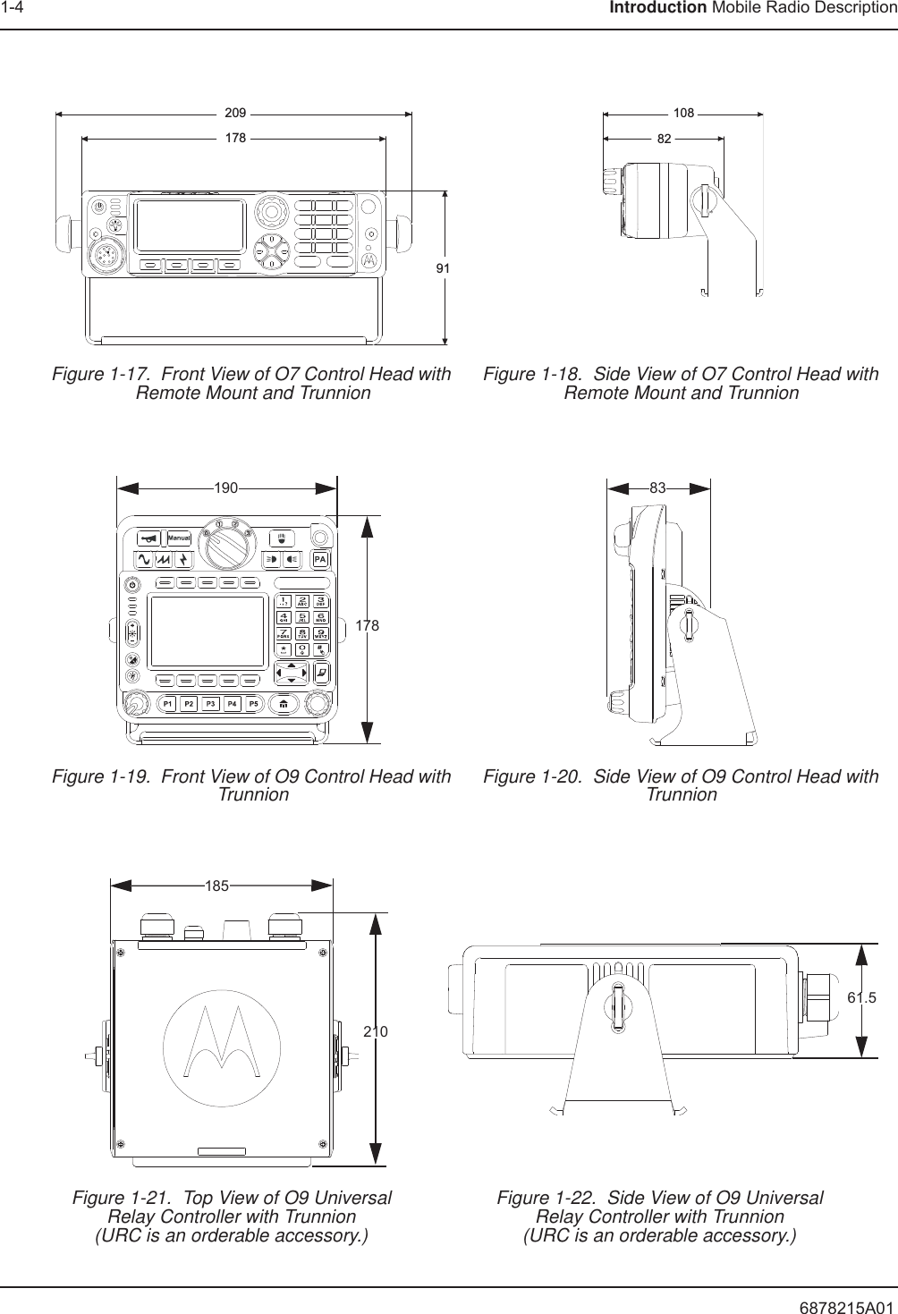
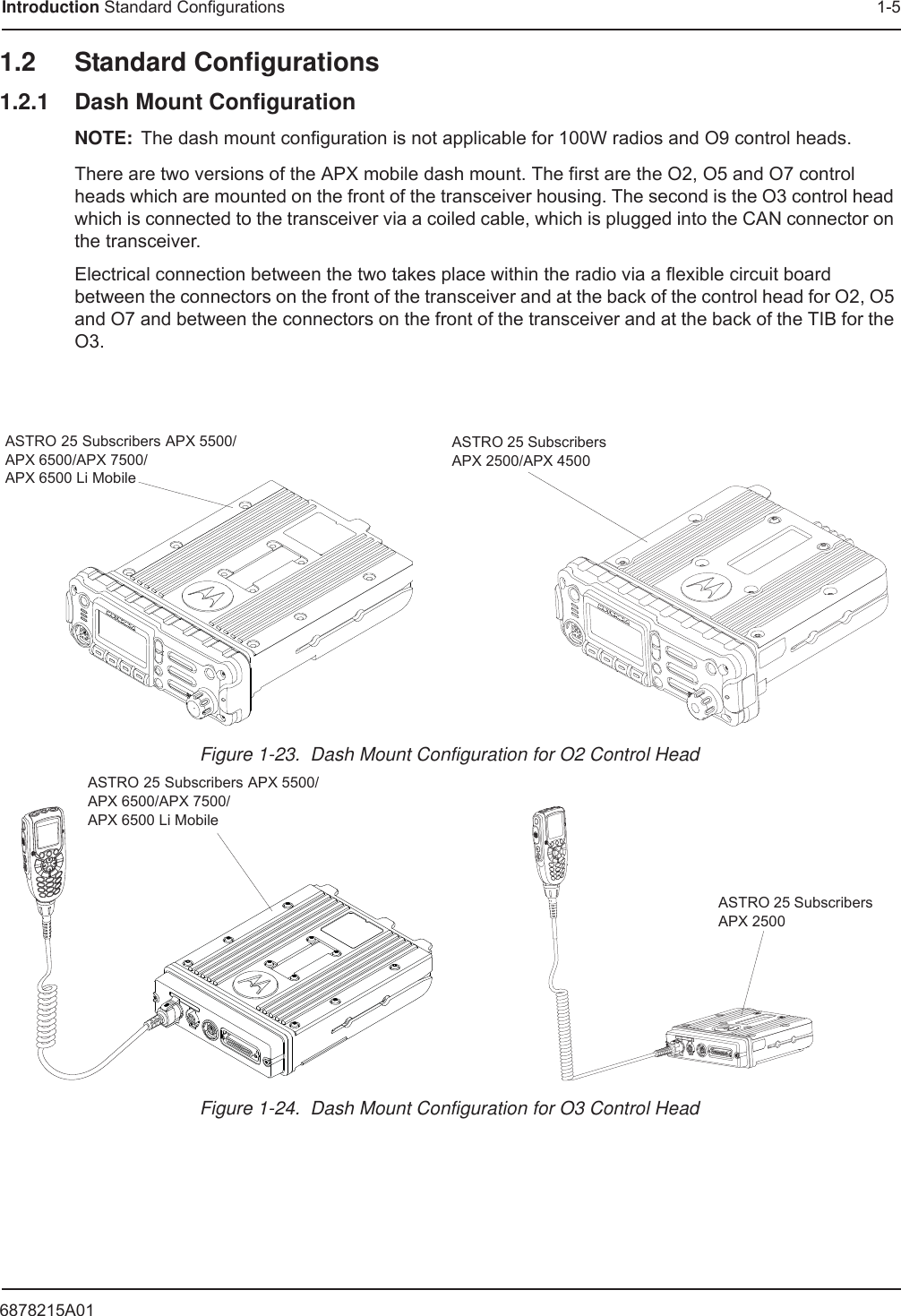
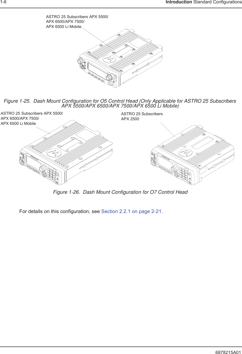
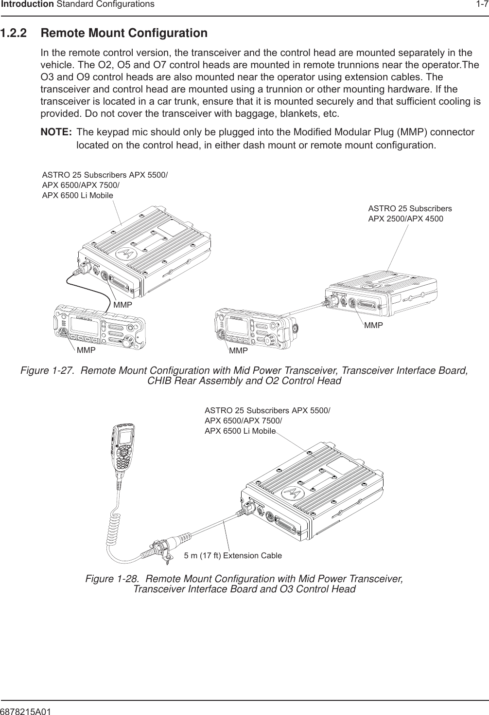
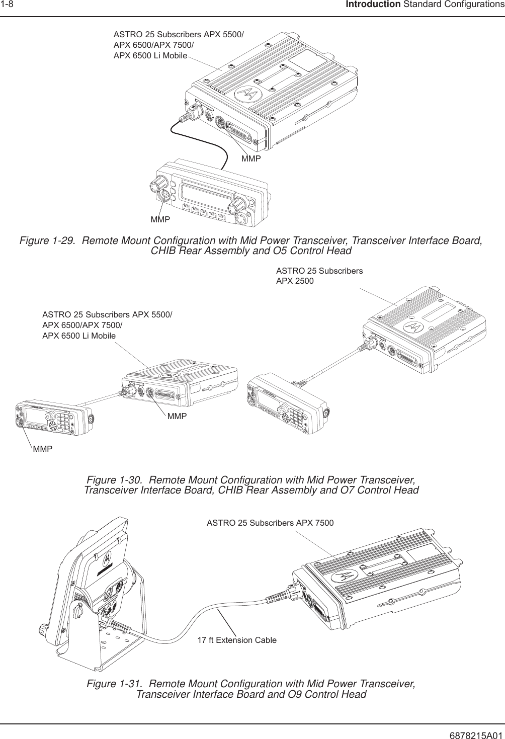
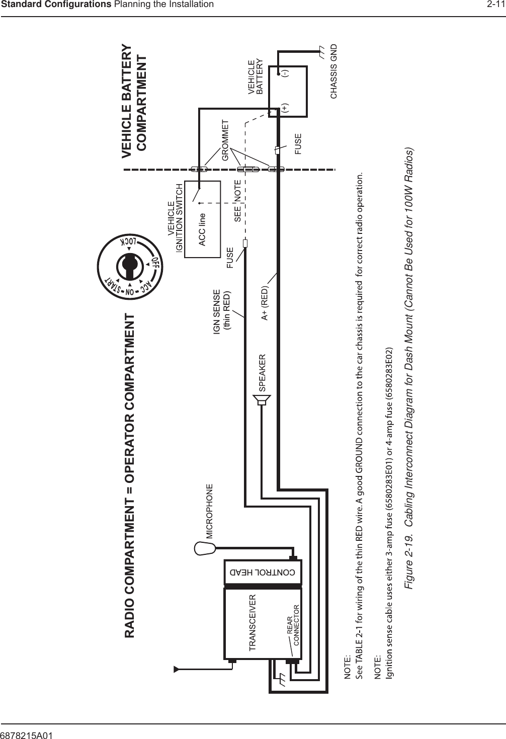
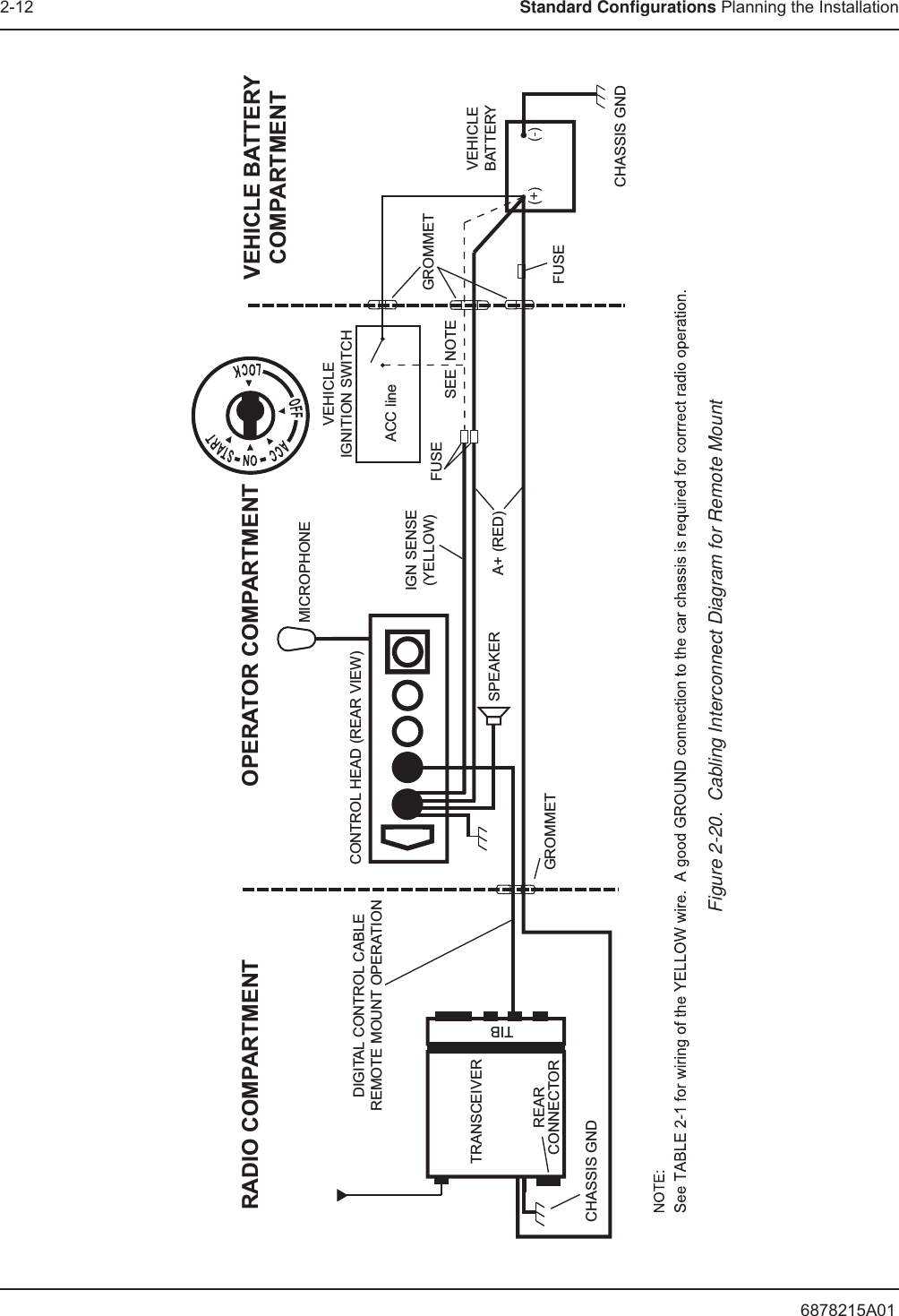
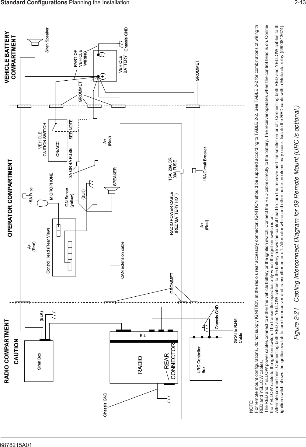
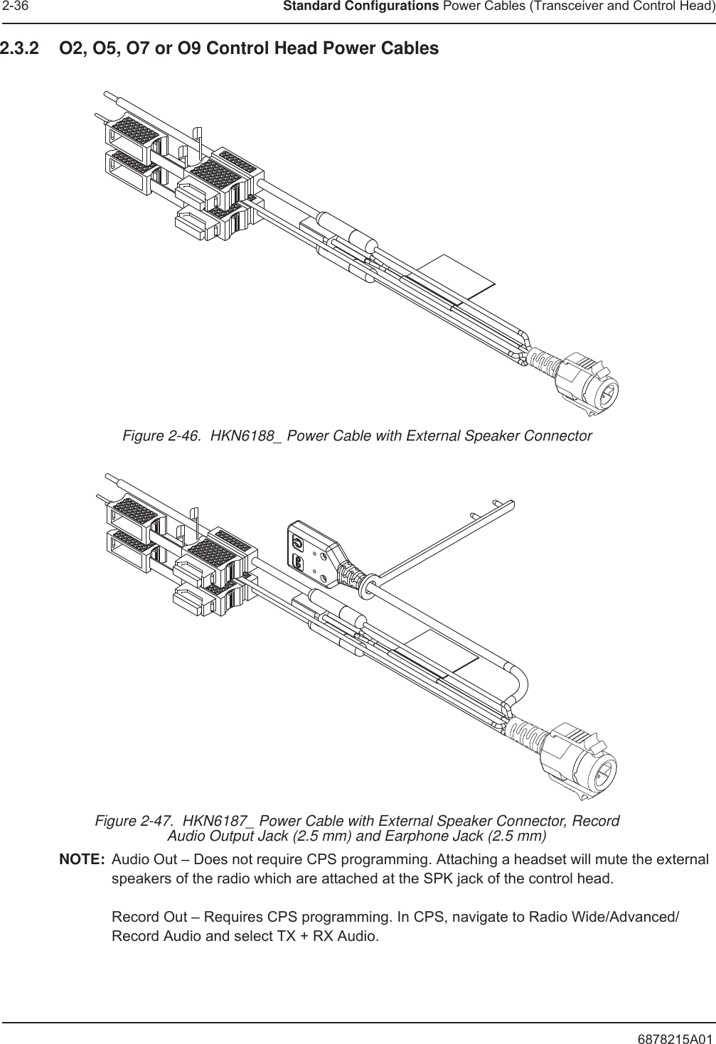
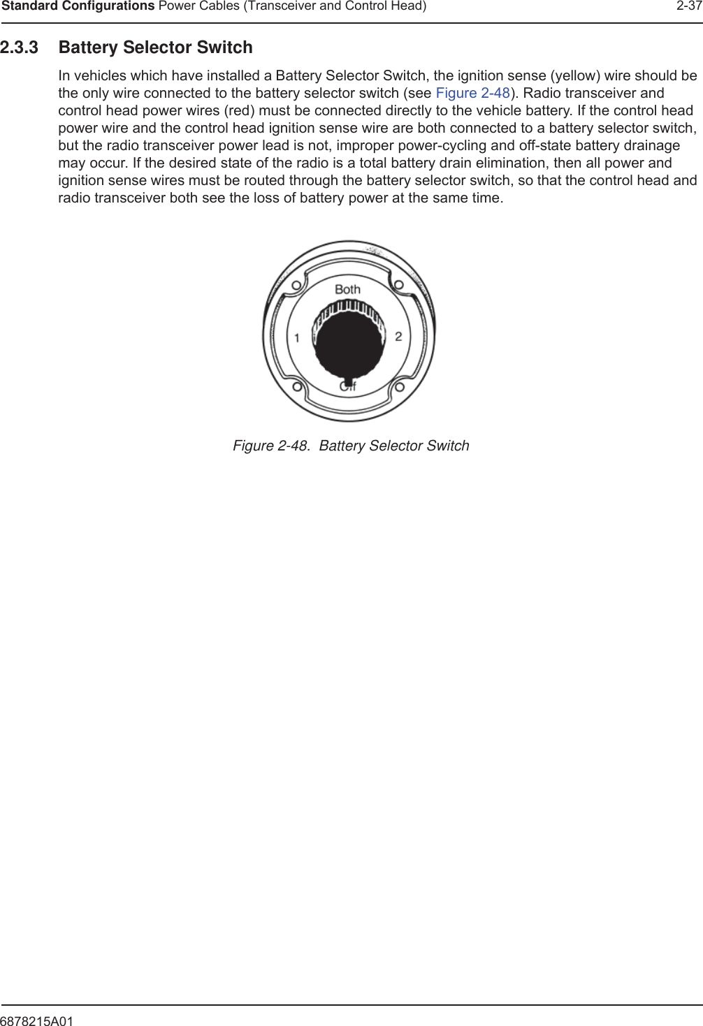
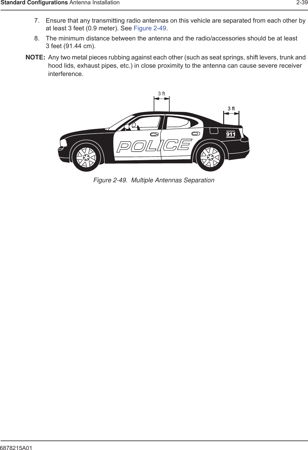
Installation Manual 1 of 2