Motorola Solutions 92FT5826 Integrated Transceiver (IDEN iO1500R) User Manual Exhibit 8 Users Manual
Motorola Solutions, Inc. Integrated Transceiver (IDEN iO1500R) Exhibit 8 Users Manual
UserManual.wiki
>
Motorola Solutions
>
92FT5826 User Manual
Exhibit 8 Users Manual
Navigation menu
Upload a User Manual
Namespaces
Wiki Guide
HTML
PDF
Info
Views
User Manual
Discussion / Help
Navigation
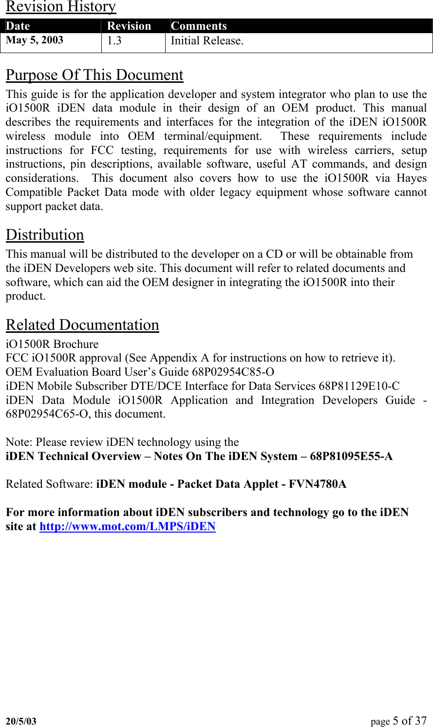
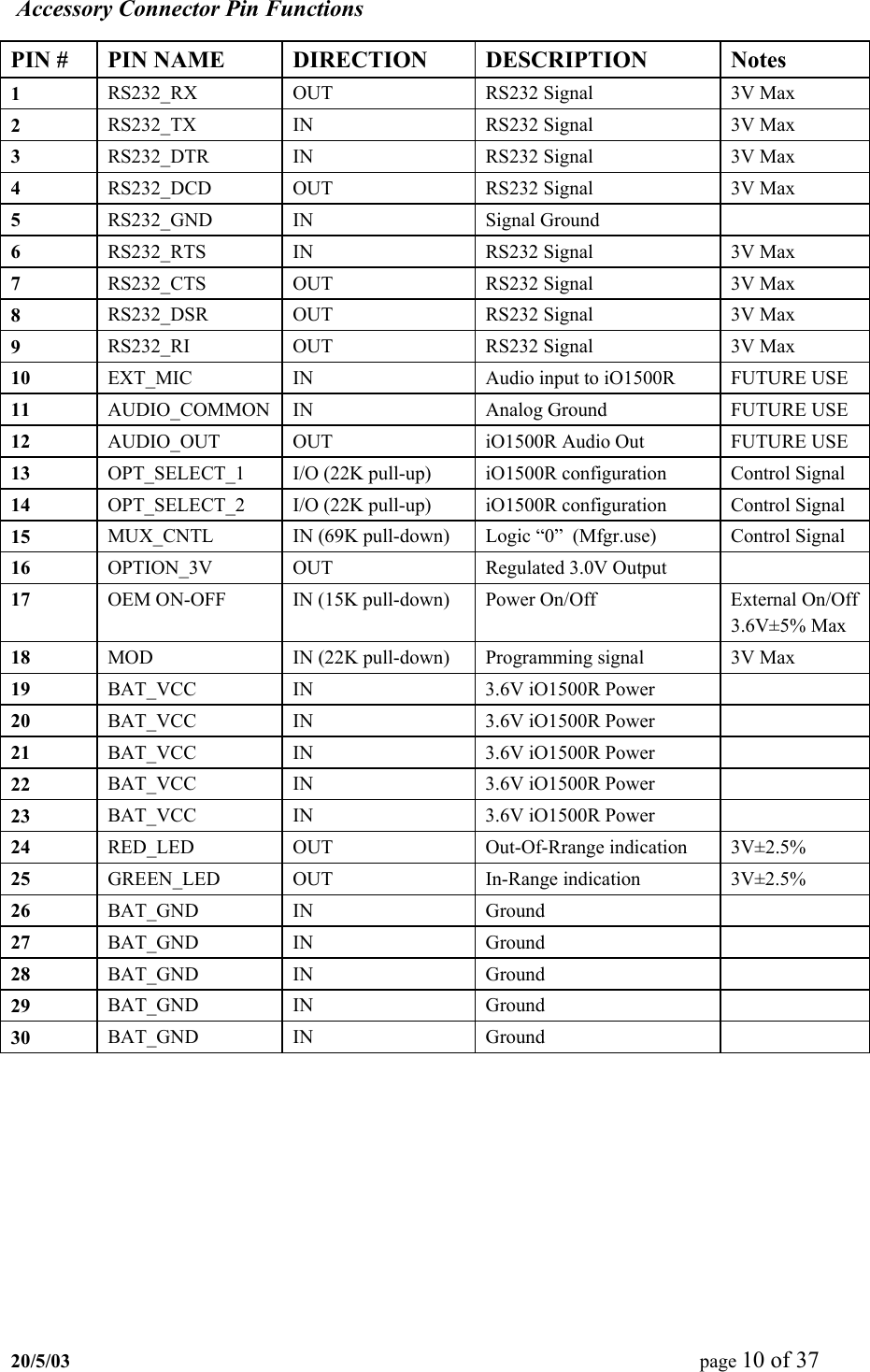
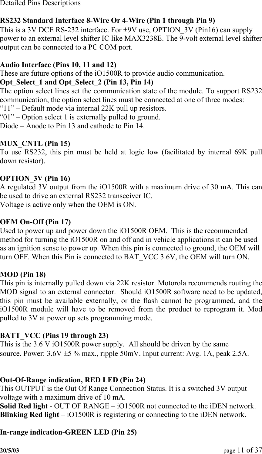
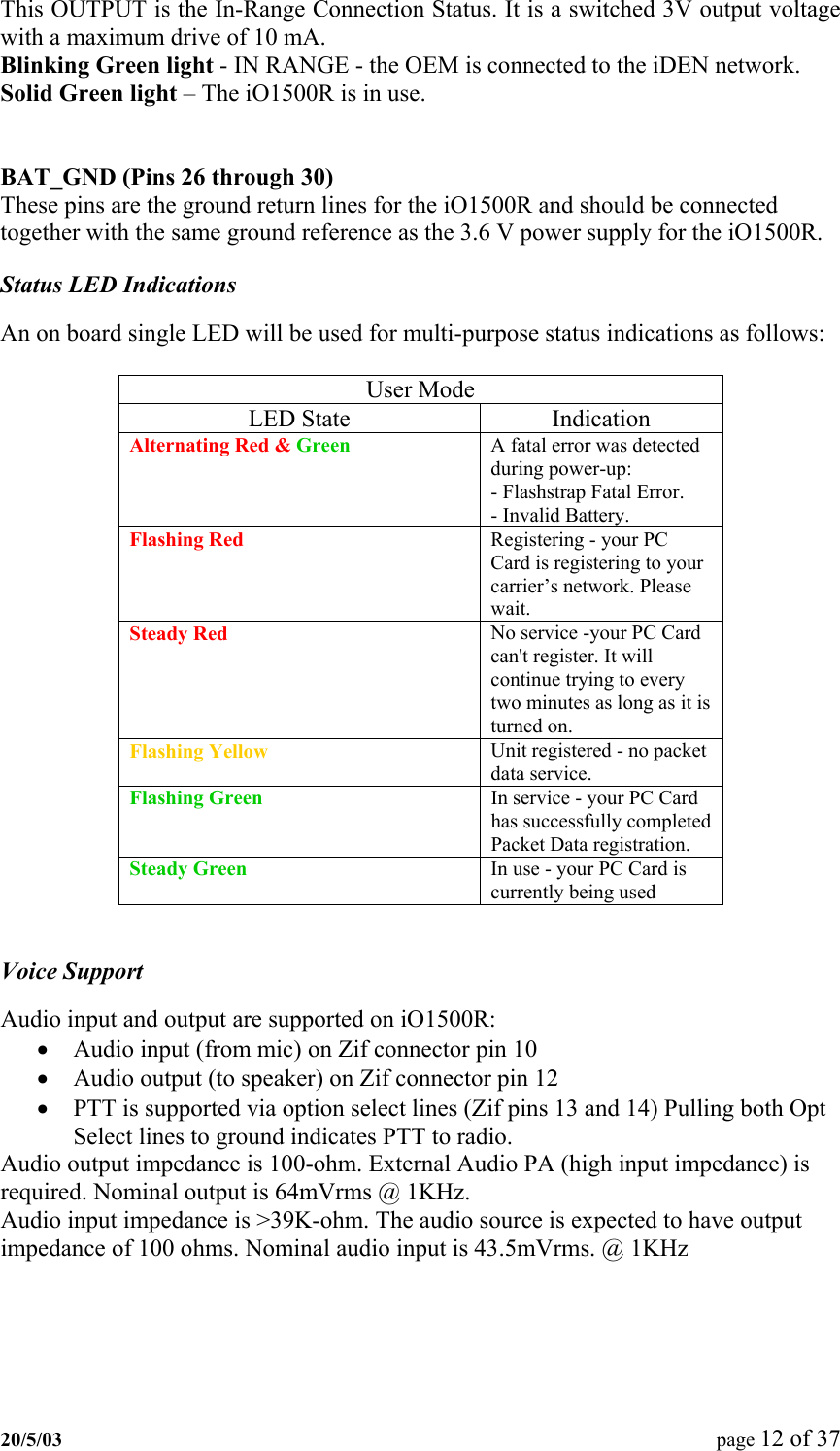
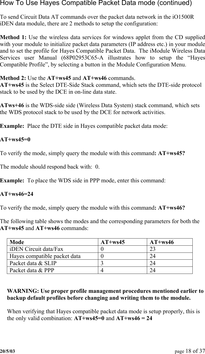
![SSL Command response The SSL AT command response will have the following syntax: DISPATCH [IS,NS (2 bytes)] [ACPT, RJCT, N_AT (4 bytes)] [RNC (6 bytes)] [0-4 cause codes, 2 bytes each, separated by comma] INTERCONNECT [IS,NS (2 bytes)] [ACPT, RJCT, N_AT (4 bytes)] [RNC (6 bytes)] [0-4 cause codes, 2 bytes each, separated by comma] PACKET DATA [IS,NS (2 bytes)] [ACPT, RJCT, N_AT (4 bytes)][RNC (6 bytes)] [0-4 cause codes, 2 bytes each, separated by comma] MOBILE IP [IS,NS (2 bytes)] [ACPT, RJCT, N_AT (4 bytes)][RNC (6 bytes)] [0-4 cause codes, 2 bytes each, separated by comma] PHONE RST [IS,NS (2 bytes)] [RSTR, N_AT (4 bytes)] [RNC 6 bytes] [0-4 cause codes, 2 bytes each, separated by comma] Each SSL entry is presented in one line. The [ ] signs indicate a field with possible values and length. PC Applications To Control the iO1500R FVN4780A - iDEN module - Packet Data Applet This program can be used with the iO1500R sitting on the Evaluation Board. See the iM1000 Data Module User's Guide - 68P02953C65-A for detailed description about how to install and use this program. The complete application is composed of three software modules: Status Program, Configuration Program and Service Program. Status Program The Status Program window is a Windows only program that is part of the module applet, and provides an enhanced method of starting a PPP or SLIP connection to the module. It also provides some helpful information about the DCE (iO1500R OEM Module) and Packet Data communication. For example the program can display RSSI, Kbytes sent/received and more. Configuration Program The Configuration Program provides a method for configuring and displaying networking parameters (Primary and secondary DNS, Server IP address, etc.) and modem parameters for packet data services. It provides a method for customizing user settings (for example: Master Reset, SIM PIN change/unblock/enable/disable, etc.) and allows the user to define the default data service. Service Program The Service Program is a GUI that provides service technicians a method to perform field-testing for an iO15 modem. 20/5/03 page 22 of 37](https://usermanual.wiki/Motorola-Solutions/92FT5826/User-Guide-339274-Page-22.png)