Motorola Solutions 92FT5826 Integrated Transceiver (IDEN iO1500R) User Manual Exhibit 8 Users Manual
Motorola Solutions, Inc. Integrated Transceiver (IDEN iO1500R) Exhibit 8 Users Manual
Exhibit 8 Users Manual

iDEN Data Module iO1500R
Application and Integration
Developers Guide
Release 1.3 May 15, 2003
Documentation Copyrights
No duplication or distribution of this document or any portion thereof shall take place
without the express written permission of Motorola. No part of this manual may be
reproduced, distributed, or transmitted in any form or by any means, electronic or
mechanical, for any purpose without the express written permission of Motorola. To
order additional copies contact your Motorola sales representative.
© 2003 Motorola All rights Reserved
68P02954C65-O
20/5/03 page 1 of 37

DECLARATION OF CONFORMITY
Per FCC CFR 47 part 2 Section 2.1077(a)
Hereby declares that the product:
Conforms to the following regulation:
FCC Part 15, subpart B
Class B Computer Peripheral Device
Date: MAY 15, 2003
Responsible party name: Motorola Inc.
Address: 8000 West Sunrise Boulevard,
Plantation, FL 33322 USA
Phone number: 1
(
800
)
453-0920
Product name: iO1500R
Model Number: F2572A
FCC ID:
A
Z492FT5826
N
ote: This equipment has been tested and found to comply with the limits for a
Class B digital device, pursuant to part 15 of the FCC Rules. These limits are designed
to provide reasonable protection against harmful interference in a residential
installation. This equipment generates, uses and can radiate radio frequency energy
and, if not installed and used in accordance with the instructions, may cause harmful
interference to radio communications. However, there is no guarantee that interference
will not occur in a particular installation.
If this equipment does cause harmful interference to radio or television reception,
which can be determined by turning the equipment off and on, the user is encouraged
to try to correct the interference by one or more of the following measures:
-- Reorient or relocate the receiving antenna.
-- Increase the separation between the equipment and receiver.
-- Connect the equipment into an outlet on a circuit different from that to which
the receiver is connected.
-- Consult the dealer or an experienced radio/TV technician for help.
20/5/03 page 2 of 37
DECLARATION OF CONFORMITY ..................................................................................2
Revision History .......................................................................................................................5
Purpose Of This Document......................................................................................................5
Distribution ...............................................................................................................................5
Related Documentation............................................................................................................5
Module Descriptions and Specifications.................................................................................6
iO15 Modem Product Specificationss ......................................................................6
Electrical specifications: ........................................................................................6
Environmental Specifications ................................................................................6
Other Specifications...............................................................................................6
iO1500R Evaluation board ......................................................................................................7
Safety Notice - ATTENTION .................................................................................................7
FCC Regulation - Letter of Notice.............................................................................7
iO1500R Hardware Interfacing Information.........................................................................8
Mechanical Dimensions.............................................................................................8
Connector Types:.......................................................................................................9
Accessory Connector Pin Functions ........................................................................10
Status LED Indications ............................................................................................12
Voice Support ..........................................................................................................12
Design Considerations For iO1500R OEM Developers ......................................................13
Hardware Considerations.........................................................................................13
Software Considerations ..........................................................................................13
Module Software And Interface Modes ...............................................................................14
Circuit Switched Data..........................................................................................14
Packet Data ..........................................................................................................14
Managing User Image Profiles ..............................................................................................15
Warning When Switching User Image Profiles.......................................................15
Setting The Active User Image................................................................................15
Properly configuring, saving, and restoring user image profiles.............................16
Changing the settings of a user image .................................................................16
Restoring the settings of a saved user image .......................................................16
How To Use Hayes Compatible Packet Data mode.............................................................17
How to use Hayes Compatible Packet Data mode (Continued) ..........................19
Other Useful AT Commands ...............................................................................19
Reset, Master Reset,Power off.................................................................................20
AT Command To RESET the iO1500R. .............................................................20
AT Command For Master Reset..........................................................................20
AT Command To Power the iO15 off. ................................................................20
SIM AT commands,.................................................................................................20
AT Command To Unlock the iO15 SIM card. ....................................................20
AT Command To enable or disable the SIM PIN lock mechanism. ...................21
Other useful iO15 AT commands ............................................................................21
Service Status Log (SSL) AT command..............................................................21
PC Applications To Control the iO1500R...............................................................22
FVN4780A - iDEN module - Packet Data Applet...............................................22
Status Program.....................................................................................................22
Configuration Program ........................................................................................22
Service Program...................................................................................................22
iDEN data modules – Software integration..........................................................................23
20/5/03 page 3 of 37
Additional Information For Registering and Going Offline ..............................................25
Module Activation and Registration........................................................................25
To make the iO1500R module re-register perform these steps: ..........................25
Monitoring The RS232 CD pin and Going Offline: ............................................25
Packet Data Status Information Command..........................................................26
IP Address/ Network Entity Identifier (NEI) Command .....................................27
Summary Of AT Commands.................................................................................................28
General AT Commands..............................................................................................28
User Image Profile Management Commands..................................................................28
Hayes Compatible Packet Data Commands ....................................................................28
Registration, Reset, and power off Commands................................................................28
SIM card management Commands ...............................................................................28
Network Status Commands.........................................................................................29
Appendix A: Requirements For FCC Testing .....................................................................30
20/5/03 page 4 of 37

Revision History
Date Revision Comments
May 5, 2003 1.3 Initial Release.
Purpose Of This Document
This guide is for the application developer and system integrator who plan to use the
iO1500R iDEN data module in their design of an OEM product. This manual
describes the requirements and interfaces for the integration of the iDEN iO1500R
wireless module into OEM terminal/equipment. These requirements include
instructions for FCC testing, requirements for use with wireless carriers, setup
instructions, pin descriptions, available software, useful AT commands, and design
considerations. This document also covers how to use the iO1500R via Hayes
Compatible Packet Data mode with older legacy equipment whose software cannot
support packet data.
Distribution
This manual will be distributed to the developer on a CD or will be obtainable from
the iDEN Developers web site. This document will refer to related documents and
software, which can aid the OEM designer in integrating the iO1500R into their
product.
Related Documentation
iO1500R Brochure
FCC iO1500R approval (See Appendix A for instructions on how to retrieve it).
OEM Evaluation Board User’s Guide 68P02954C85-O
iDEN Mobile Subscriber DTE/DCE Interface for Data Services 68P81129E10-C
iDEN Data Module iO1500R Application and Integration Developers Guide -
68P02954C65-O, this document.
Note: Please review iDEN technology using the
iDEN Technical Overview – Notes On The iDEN System – 68P81095E55-A
Related Software: iDEN module - Packet Data Applet - FVN4780A
For more information about iDEN subscribers and technology go to the iDEN
site at http://www.mot.com/LMPS/iDEN
20/5/03 page 5 of 37

Module Descriptions and Specifications
The iO1500R module for iDEN is a wireless subscriber device for providing packet
data and circuit data connectivity over the iDEN 800MHz infrastructure.
The module is supported by PC applications for installation, monitoring, service and
development for the OEM and the system integrator.
iO1500R Module Product Specificationss
Electrical specifications:
Frequency TX 806-825 MHz
RX 851-870 MHz
TX Output Power Average 0.6 watts at nominal 3.6V & 25 °C
Input Voltage 3.6VDC +/- 5 % ripple 50mv
Current Consumption Standby Current avg. 20mA
Tx Current in slot Avg. 1:6 1000mA Max
Rx Current in slot Avg. 1:6 100 mA Max
Tx. Modulation
Circuit Data / Voice Quad -16 QAM;
Packet Data Quad-64 QAM, Quad-16 QAM and QPSK;
Trans. ACCPR -60 dB @ 25 KHz
-74.5 dB @ 1000 KHz
Static Rx Sensitivity -111 dBm @ -10% BER
Environmental Specifications
Operating Temp -25°C to 60°C
Storage Temp -40°C to 85°C
Humidity: 95% RH @ 50°C , non condensing
Vibration: Sine TIA/EIA 603 Para. 3.3.4
Shock TIA/EIA 603 Para. 3.3.5
Other Specifications
Size 85.6 X 57.7 X 6.0mm
Weight 30 grams
For module description, features and specifications refer to the iO1500R brochure or
get the information from the WEB at http://ml800.motorola.com/=>Module Modems
=> iO1500R.
20/5/03 page 6 of 37

iO1500R Evaluation board
The evaluation board helps the developer and system integrator to start development
of the software before their terminal hardware is ready. The developer can connect a
PC to the evaluation board and communicate with the iO1500R that is registered to
the system and work over the iDEN infrastructure. For more information see the OEM
Evaluation Board User Guide 68P02954C85-O.
Safety Notice - ATTENTION
This iDEN iO1500R Module is restricted to occupational use only to satisfy
FCC RF energy exposure requirements. Before using this product, read the RF energy
awareness information and operating instructions in the Product Safety and RF
Exposure booklet (Motorola Publication part number 6881095C99) to ensure
compliance with RF energy exposure limits.
FCC Regulation - Letter of Notice
As you know, the iO1500R RF module that we are supplying to you for incorporation
into Final Products are components that, when connected to the power supply, internal
signaling, and antenna in a Final Product can receive and transmit module signals.
In the United States, the Federal Communications Commission requires that many
module transmitting devices obtain approval before being offered on the market,
unless the device is exempt. While the iO1500R has been designed to meet applicable
FCC requirements, provided in the code of Federal Regulation 47CFR part II subpart
J and 47CFR part 90 subpart S, the Final Product's compliance with the FCC's
requirements, including RF energy exposure requirements, must reflect product usage,
positioning of the iO1500R within the product, the type of antenna used, the location
of the antenna, and other factors that may vary with the design and nature of the Final
Product. Therefore, compliance with such FCC requirements can only be determined
by an assessment of the Final Product.
It is important that any manufacturer to whom you resell the iO1500R for use in a
final product also recognize that they will have the responsibility for taking all
necessary steps to ensure that the Final Product meets any applicable FCC
requirements and for obtaining any necessary approval from the FCC for sale and
operation of the Final Product. To the extent that this may require testing and
assessment of the Final Product, this will be the responsibility of the manufacturer.
To the extent that this may require development of user information or guidance to be
provided to each purchaser of the Final Product, this will also be the responsibility of
the manufacturer.
Information covering the FCC tests that are required is located in Appendix A.
Please provide a copy of this reminder to every manufacturer to whom you resell these products.
20/5/03 page 7 of 37
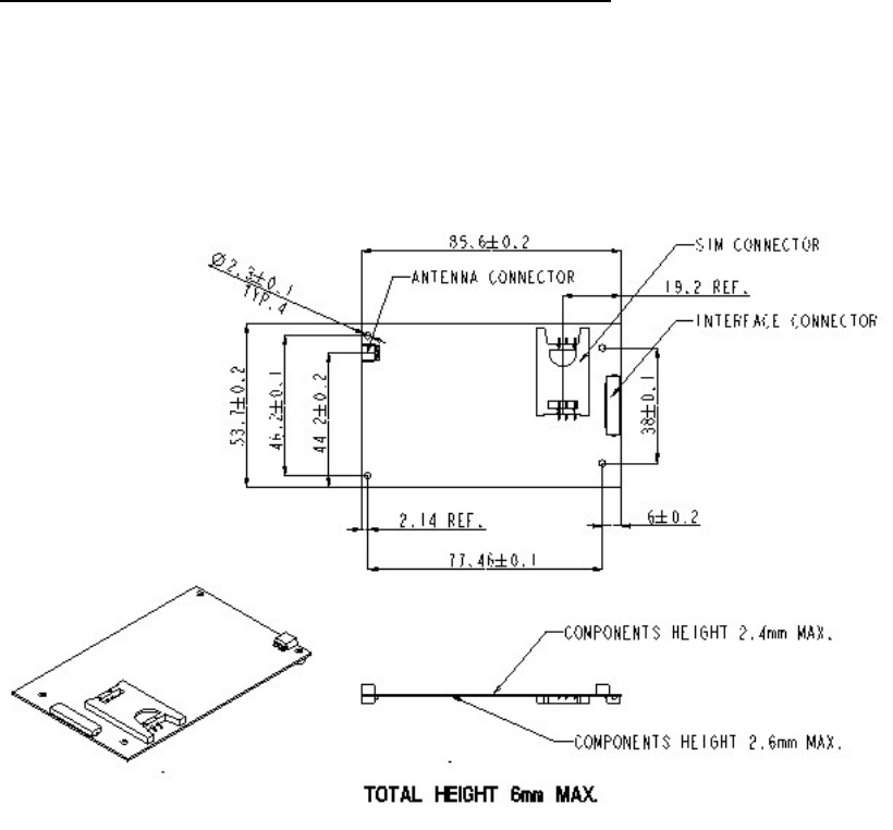
iO1500R Hardware Interfacing Information
Mechanical Dimensions
20/5/03 page 8 of 37
Connector Types:
The unit has two connectors:
• RF output connector MMCX Jack (female) 50 Ohm. This will accept the
RG 178-11 MMCX-50-1-1 Plug (male) or RG 316-11 MMCX-50-2-3 (male).
The Data Interface connector is a MOLEX 30-pin ZIF connector,
MOLEX part #: 52892-3090.
Motorola Part #: 0909059E06.
OEM developers must also use this 30-wire flex cable to interface to the
connector:
AXON Cable Part#: FFC0.50A30/0035L3-3-06-06SBBB.
Motorola Part #: 3086229J04.
20/5/03 page 9 of 37

Accessory Connector Pin Functions
PIN # PIN NAME DIRECTION DESCRIPTION Notes
1 RS232_RX OUT RS232 Signal 3V Max
2 RS232_TX IN RS232 Signal 3V Max
3 RS232_DTR IN RS232 Signal 3V Max
4 RS232_DCD OUT RS232 Signal 3V Max
5 RS232_GND IN Signal Ground
6 RS232_RTS IN RS232 Signal 3V Max
7 RS232_CTS OUT RS232 Signal 3V Max
8 RS232_DSR OUT RS232 Signal 3V Max
9 RS232_RI OUT RS232 Signal 3V Max
10 EXT_MIC IN Audio input to iO1500R FUTURE USE
11 AUDIO_COMMON IN Analog Ground FUTURE USE
12 AUDIO_OUT OUT iO1500R Audio Out FUTURE USE
13 OPT_SELECT_1 I/O (22K pull-up) iO1500R configuration Control Signal
14 OPT_SELECT_2 I/O (22K pull-up) iO1500R configuration Control Signal
15 MUX_CNTL IN (69K pull-down) Logic “0” (Mfgr.use) Control Signal
16 OPTION_3V OUT Regulated 3.0V Output
17 OEM ON-OFF IN (15K pull-down) Power On/Off External On/Off
3.6V±5% Max
18 MOD IN (22K pull-down) Programming signal 3V Max
19 BAT_VCC IN 3.6V iO1500R Power
20 BAT_VCC IN 3.6V iO1500R Power
21 BAT_VCC IN 3.6V iO1500R Power
22 BAT_VCC IN 3.6V iO1500R Power
23 BAT_VCC IN 3.6V iO1500R Power
24 RED_LED OUT Out-Of-Rrange indication 3V±2.5%
25 GREEN_LED OUT In-Range indication 3V±2.5%
26 BAT_GND IN Ground
27 BAT_GND IN Ground
28 BAT_GND IN Ground
29 BAT_GND IN Ground
30 BAT_GND IN Ground
20/5/03 page 10 of 37

Detailed Pins Descriptions
RS232 Standard Interface 8-Wire Or 4-Wire (Pin 1 through Pin 9)
This is a 3V DCE RS-232 interface. For ±9V use, OPTION_3V (Pin16) can supply
power to an external level shifter IC like MAX3238E. The 9-volt external level shifter
output can be connected to a PC COM port.
Audio Interface (Pins 10, 11 and 12)
These are future options of the iO1500R to provide audio communication.
Opt_Select_1 and Opt_Select_2 (Pin 13, Pin 14)
The option select lines set the communication state of the module. To support RS232
communication, the option select lines must be connected at one of three modes:
“11” – Default mode via internal 22K pull up resistors.
“01” – Option select 1 is externally pulled to ground.
Diode – Anode to Pin 13 and cathode to Pin 14.
MUX_CNTL (Pin 15)
To use RS232, this pin must be held at logic low (facilitated by internal 69K pull
down resistor).
OPTION_3V (Pin 16)
A regulated 3V output from the iO1500R with a maximum drive of 30 mA. This can
be used to drive an external RS232 transceiver IC.
Voltage is active only when the OEM is ON.
OEM On-Off (Pin 17)
Used to power up and power down the iO1500R OEM. This is the recommended
method for turning the iO1500R on and off and in vehicle applications it can be used
as an ignition sense to power up. When this pin is connected to ground, the OEM will
turn OFF. When this Pin is connected to BAT_VCC 3.6V, the OEM will turn ON.
MOD (Pin 18)
This pin is internally pulled down via 22K resistor. Motorola recommends routing the
MOD signal to an external connector. Should iO1500R software need to be updated,
this pin must be available externally, or the flash cannot be programmed, and the
iO1500R module will have to be removed from the product to reprogram it. Mod
pulled to 3V at power up sets programming mode.
BATT_VCC (Pins 19 through 23)
This is the 3.6 V iO1500R power supply. All should be driven by the same
source. Power: 3.6V ±5 % max., ripple 50mV. Input current: Avg. 1A, peak 2.5A.
Out-Of-Range indication, RED LED (Pin 24)
This OUTPUT is the Out Of Range Connection Status. It is a switched 3V output
voltage with a maximum drive of 10 mA.
Solid Red light - OUT OF RANGE – iO1500R not connected to the iDEN network.
Blinking Red light – iO1500R is registering or connecting to the iDEN network.
In-range indication-GREEN LED (Pin 25)
20/5/03 page 11 of 37

This OUTPUT is the In-Range Connection Status. It is a switched 3V output voltage
with a maximum drive of 10 mA.
Blinking Green light - IN RANGE - the OEM is connected to the iDEN network.
Solid Green light – The iO1500R is in use.
BAT_GND (Pins 26 through 30)
These pins are the ground return lines for the iO1500R and should be connected
together with the same ground reference as the 3.6 V power supply for the iO1500R.
Status LED Indications
An on board single LED will be used for multi-purpose status indications as follows:
User Mode
LED State Indication
Alternating Red & Green A fatal error was detected
during power-up:
- Flashstrap Fatal Error.
- Invalid Battery.
Flashing Red Registering - your PC
Card is registering to your
carrier’s network. Please
wait.
Steady Red No service -your PC Card
can't register. It will
continue trying to every
two minutes as long as it is
turned on.
Flashing Yellow Unit registered - no packet
data service.
Flashing Green In service - your PC Card
has successfully completed
Packet Data registration.
Steady Green In use - your PC Card is
currently being used
Voice Support
Audio input and output are supported on iO1500R:
• Audio input (from mic) on Zif connector pin 10
• Audio output (to speaker) on Zif connector pin 12
• PTT is supported via option select lines (Zif pins 13 and 14) Pulling both Opt
Select lines to ground indicates PTT to radio.
Audio output impedance is 100-ohm. External Audio PA (high input impedance) is
required. Nominal output is 64mVrms @ 1KHz.
Audio input impedance is >39K-ohm. The audio source is expected to have output
impedance of 100 ohms. Nominal audio input is 43.5mVrms. @ 1KHz
20/5/03 page 12 of 37

Design Considerations For iO1500R OEM Developers
Hardware Considerations
• Developers need to work with carriers to approve applications on their network.
• The end product must display the IMEI and serial # of the module.
• The module must use OEM_ON-OFF (Pin 17) to power on and off.
• Be aware of current consumption when unit is not registered.
• The external connector on the end product MUST have direct access connections
to the iO1500R’s PINS, with no relays through other microprocessors or buffers.
• The end product needs FCC approval
• Developers need system test procedures for production processes.
• Developers need to be aware of the requirements of certain pins, mentioned in
the pin description section in order to communicate via RS232.
• Care should be taken when interfacing RS232 lines to external interfaces. RS232
pins must not exceed 3.0 volts or the iO1500R will be damaged.
• To use RS232, the MUX_CNTL input (pin 15) must be held at logic low
(internal pull down provided).
• The MOD pin is pulled low through an internal 22 KOhm resistor. Motorola
recommends routing the MOD signal to an external connector.
Software Considerations
• When integrating the unit inside a terminal, it is required that the user will have
access to the module basic service utilities such as: Master Reset, RSSI Display,
SQE Display and others. This is accomplished by use of AT commands, as
explained later in this document.
• The end product needs to be able to perform a Module Reset and Master Reset
commands on the module.
• It is recommended that the unit will be able to display system registration
information and RSSI/SQE readings.
• Developers who change default User Image profiles must use proper profile
management processes outlined in this document to properly back them up
before overwriting them. Packet data services can be lost if this is not handled
properly.
• Developers should be able to implement network specific status messages to the
end user as an aid for users and for customer care to query the current status the
iO1500R.
20/5/03 page 13 of 37

Module Software And Interface Modes
The iO1500R supports both circuit data over packet data and standard packet data
modes. DCE refers to the iDEN iO1500R Module. DTE refers to a computer or data
terminal equipment that is connected to the iO1500R Module. Below are the
descriptions for each of these data modes.
Circuit Switched Data
The iO1500R Module and the iDEN network interact to provide the DTE with a
circuit-switched data interface with the PSTN.
The iDEN infrastructure and data subscribers support circuit data based on
TIA/EIA-602 (commonly known as the “Hayes AT Command set” defines
messages and procedures that allow a DTE to control the operation of a DCE. The
DCE provides dialing, answering, and module services. The messages consists of
async ASCII (readable) characters and are sent “in band” between the DTE and
DCE (i.e. over the same interface used to transfer the data).
See the iDEN Mobile Subscriber DTE/DCE Interface for Data Services
68P81129E10-C for detailed AT command descriptions. See “How to use Hayes
Compatible Packet Data mode” for iDEN data module AT commands.
Packet Data
The iDEN Packet Data service provides wireless datagram-based networking on the
iDEN network. Based on the TCP/IP protocol suite, iDEN Packet Data provides a
mobile transport layer connecting the mobile node to the Internet.
The conventional method of using iDEN Packet Data (PD) service is via data terminal
equipment (DTE) containing a TCP/IP protocol stack.
A DTE connected to an iDEN data module will be able to use IP protocol to transfer
data to any IP capable device. For example it will be able to FTP a host computer and
browse an Internet site.
20/5/03 page 14 of 37

Managing User Image Profiles
The iO1500R ships with 3 configurable User Images (Profile 0, Profile 1, and Profile
2)
User Image 0 Profile 0 stores the default factory settings for Circuit Data calls.
User Image 1 Profile 1 is a scratchpad where Profile 0 or Profile 2 is stored by the
developer when changing the default settings of Profile 0 or Profile 2.
User Image 2 Profile 2 stores the default factory IP settings for Packet Data or
Hayes Compatible Packet Data services.
The iO1500R units ship from factory with the User Image Profile defaulted to Image
2.
Warning When Switching User Image Profiles
Developers should use caution when changing default settings of User Image Profiles
in the iO1500R. Before settings of a profile are changed, they should be backed up
into the User Image 1 scratchpad for safe keeping, then restored later. If these
backups are not performed, then the module will lose setup information and will not
be able to use Packet Data services. The recovery from this failure uses severl AT
commands to restore all the vraibles one by one. Use this profile management
process:
1) Set the user default image to the image profile that is to be modififed.
2) Copy that user image profile into the scratchpad user image profile 1.
3) Then change the original image to the new desired settings.
4) When the user is finished using the custom settings, copy the original backed
up profile from scratchpad user image profile 1 back to the original profile.
Setting The Active User Image
The ATz command sets the active User Image
This loads the specified user image profile from ROM into active RAM.
Usage: ATz<image> (where image can be 0,1 or 2)
User Image 0 Make Circuit Data the active image.
User Image 1 Make the scratchpad the active image.
User Image 2 Load the module with Packet Data parameters.
The iO1500R units ship from the factory defaulted to Image 2.
Example: To select circuit data (Image 0), enter this AT command: ATz0
Example: To select packet data (Image 2), enter this AT command: ATz2
20/5/03 page 15 of 37

Properly configuring, saving, and restoring user image profiles
Here is an example of how to properly manage the user image profile AT commands.
Example: The module by default boots up in User Image Profile 2, which is packet
data mode. This example will back up Profile 2 into Profile 1 for safe keeping, then
change Profile 2 to become Circuit Data, and save these settings permanently into to
Module ROM so that the module boots up into Circuit Data mode.
Changing the settings of a user image
1) Make User Image 2 the active image: ATz2
2) View stored parameters to verify: AT&V
3) Save Profile 2 to Profile 1 for safekeeping: AT&W1
4) Now make User Image 0 the active image so parameters can be copied: ATz0
5) Write the Profile 0 parameters to Profile 2: AT&W2
6) Make User Image 2 the active image to verify the change took place: ATz2
7) View stored parameters: AT&V
The module will now power up in Profile 2, which was customized to be in circuit
data mode by the above example. To recover Profile 2, do the following steps:
Restoring the settings of a saved user image
1) Make User Image 1 the active image to recover the Image 2 profile data: ATz1
2) View stored parameters to verify: AT&V
3) Save Profile 1 to Profile 1 for safekeeping: AT&W2
4) Make User Image 2 the active image to verify the change took place: ATz2
5) View stored parameters: AT&V
20/5/03 page 16 of 37

How To Use Hayes Compatible Packet Data mode
Some older legacy DTE equipment that the iO1500R may be interfaced to may not
have a TCP/IP stack. These devices use Hayes Module AT commands to
communicate. A non-IP interface was implemented inside the module to work with
these legacy DTEs using a simulation of Circuit Data Over Packet Data. Terminals
that are using AT-Module protocol will be thus be able to communicate with the
iDEN data modules and use the iDEN Packet Data services. This capability is only
available in the iO1500R and not the standard iDEN modules.
Circuit data over Packet data will operate as follows:
The non-IP DTE will use the AT command set described in the TIA/EIA-602
standard for Circuit Switched Data transmissions, with the following modification:
ATD<IP_address..Port_Number>
instead of :
ATD<Phone_Number>
Note: There is no Fax support while in Hayes compatible packet data mode.
An AT command interpreter, implemented in the module software, receives the
ATD<IP_address: Port_Number> command and transfers it to the Packet
Assembler/Disassembler (PAD) which prepare the data in a mobile TCP/IP format
which is recognized and transferable by the iDEN infrastructure.
The end result is circuit data interface with packet data over the air.
The user gets circuit data interface for it’s dumb terminals with the response time and
data rates of packet data.
RS232 RS232
AT modem AT modem
ApplicationApplication LAPiLAPi
Serial Link Serial Link RF Link RF Link
DTE without DTE without
TCP/IP stackTCP/IP stack
IO1500R
Infrastructure Infrastructure
IPIP
AT Interface AT Interface
IP to IPIP to IP
InterfaceInterface
RS232 RS232
TCPTCP
IPIP
PADPAD
Hayes CompatibleHayes Compatible
ImplementationImplementation
OEM module OEM module
20/5/03 page 17 of 37

How To Use Hayes Compatible Packet Data mode (continued)
To send Circuit Data AT commands over the packet data network in the iO1500R
iDEN data module, there are 2 methods to setup the configuration:
Method 1: Use the wireless data services for windows applet from the CD supplied
with your module to initialize packet data parameters (IP address etc.) in your module
and to set the profile for Hayes Compatible Packet Data. The iModule Wireless Data
Services user Manual (68P02953C65-A illustrates how to setup the “Hayes
Compatible Profile”, by selecting a button in the Module Configuration Menu.
Method 2: Use the AT+ws45 and AT+ws46 commands.
AT+ws45 is the Select DTE-Side Stack command, which sets the DTE-side protocol
stack to be used by the DCE in on-line data state.
ATws+46 is the WDS-side side (Wireless Data System) stack command, which sets
the WDS protocol stack to be used by the DCE for network activities.
Example: Place the DTE side in Hayes compatible packet data mode:
AT+ws45=0
To verify the mode, simply query the module with this command: AT+ws45?
The module should respond back with: 0.
Example: To place the WDS side in PPP mode, enter this command:
AT+ws46=24
To verify the mode, simply query the module with this command: AT+ws46?
The following table shows the modes and the corresponding parameters for both the
AT+ws45 and AT+ws46 commands:
Mode AT+ws45 AT+ws46
iDEN Circuit data/Fax 0 23
Hayes compatible packet data 0 24
Packet data & SLIP 3 24
Packet data & PPP 4 24
WARNING: Use proper profile management procedures mentioned earlier to
backup default profiles before changing and writing them to the module.
When verifying that Hayes compatible packet data mode is setup properly, this is
the only valid combination: AT+ws45=0 and AT+ws46 = 24
20/5/03 page 18 of 37

How to use Hayes Compatible Packet Data mode (Continued)
This command will then instruct the DCE (iO1500R module) to originate a call:
ATd <IP_address>..<port#>
Where <IP_Address> = n.n.n.n OR n,n,n,n where 1<n<255, and
<port#> is optional ..p or ,,p 1<=p<= 65535
<IP_address> and <port#> MUST be separated by two dots”..” or two commas
“,,”, but no matter which character is used, there must be 2 of them.
Example: ATd 128.54.88.104..80
will tell the iO1500R to connect to the IP address shown above, and through port #80.
The DCE will respond with: ”Connect <baud rate>”, which means the module is
connected at the baud rate displayed.
1. Continue to work. Transmit and receive data from the other side.
2. To disconnect the call and get back to command mode type +++.
3. The module will respond with “OK”. Then type ATH to hang up.
Other Useful AT Commands
View stored parameters with the AT&V command
To verify that the right image is used enter this command: AT&V
The iO1500R will display several lines of information regarding the current setup of
the module. The very first line of information will display “Active User Image”. If
the iO1500R is in packet data mode, the display will read “Active User Image: 2”.
The AT&V query command also displays the current status of the AT+ws45 and
AT+ws46, a sanity check to determine if the module is setup in Hayes Compatible
Packet Data mode, or any other mode.
How to configure the baud rate with the AT+IPR command
Configure the iDEN data module for the baud rate of your DTE. The default baud rate
of the module is auto baud. Do not leave as auto baud. To configure the baud rate of
the iDEN data module, use this command:
AT+IPR=baud rate
Example: AT+IPR=19200 will set the baud rate to 19200.
The status of the current baud rate setting can then be shown with the baud rate query:
AT+IPR?
The iO1500R will respond back with: +IPR: 19200
20/5/03 page 19 of 37

Reset, Master Reset,Power off
The requirements of setting these functions may vary by service provider. The
service provider may ask the developer to perform these functions, which are
accomplished through a keypad on a normal phone. But on the iO1500R, these
functions can be accomplished using the Applet program from the CD, or by using
AT commands that can be sent to the iO1500R:
AT Command To RESET the iO1500R.
This message tells the module to perform a full reset as if the module cycled power:
AT+wvreset
AT Command For Master Reset
The carrier may ask the developer to Master Reset the iO1500R when certain changes
are made, or the developer will need to Master Reset the iO1500R after new software
is flashed into the module. This is not the same as RESET, and should only be run in
the above scenarios. This is the AT command to be used:
AT+wvmr=”xxxx”
Where “xxxx” is the correct pass code. Typically on new units, the default pass code
is 0000. In most cases to perform a master reset, enter the AT command like this:
AT+wvmr”0000” (no space between any characters)
AT Command To Power the iO15 off.
This message tells the modem to perform a safe software power off:
At+wvpo
SIM AT commands,
As for Condor based product, the iO15 modem has a SIM card. The management of
the SIM cards can be done using the following AT commands:
AT Command To Unlock the iO15 SIM card.
At+wvsim
The SIM PIN should be between 4-8 digits Operator.
Operator Syntax
Execute +wvsim=”<SIM PIN>”
Query +wvsim?
Range +wvsim=?
Response:
• "NO LOCK" - in case the SIM is not locked.
20/5/03 page 20 of 37

• "SIM LOCK" - in case SIM is locked. PIN must be entered in order to unlock
the SIM.
• "PIN BLOCK" - in case the PIN is blocked due to three consecutive
unsuccessful attempts to unlock the SIM. Need to use the Configuration
Applet program and PUK code delivered by the SIM card provider in order to
unblock, or get service.
• "PUK BLOCK" - in case PUK is blocked due to ten consecutive unsuccessful
attempts to unblock the SIM PIN. The SIM has become unusable.
• "LOCK NO SIM" - There is no SIM in the radio. Need to insert SIM.
• "LOCK SIM MEM ERR" - Memory error in the SIM. Need to get service.
• "LOCK SIM TECH ERR" - Technical error in SIM. Need to get service.
• "ERROR" - All other cases.
AT Command To enable or disable the SIM PIN lock mechanism.
At+wvsimtgl
The SIM PIN should be between 4-8 digits. The first parameter indicates whether to
enable or disable the lock mechanism.
Operator Syntax
Execute +wvsimtgl=n,”<SIM PIN”
with n =0 for enable and
n=1 for disable
Query +wvsimtgl?
Range +wvsimtgl=?
Response:
• ENABLED
• DISABLED
• ERROR
Other useful iO15 AT commands
Service Status Log (SSL) AT command
To assist “customer care” in troubleshooting many of their most frequently
experienced “registration” and activation issues, the MS captures the results of DAP
registration, Location Updates, PD Registrations and MIP Registrations in a log that
can be displayed via the “diagnostic mode” menu. Also, results for Phone Restricted
can be displayed for SIM capable phones. The result of the most recent transaction
(per procedure) is saved. Any subsequent transactions will overwrite the result
previously stored. These results are only stored in volatile memory and therefore are
not stored across power ups. In Addition the log shows the current IN or OUT of
service state for DAP, LU, PD and MIP.
SSL command syntax
At+wptrace
20/5/03 page 21 of 37

SSL Command response
The SSL AT command response will have the following syntax:
DISPATCH [IS,NS (2 bytes)] [ACPT, RJCT, N_AT (4 bytes)] [RNC (6 bytes)] [0-4
cause codes, 2 bytes each, separated by comma]
INTERCONNECT [IS,NS (2 bytes)] [ACPT, RJCT, N_AT (4 bytes)] [RNC (6
bytes)] [0-4 cause codes, 2 bytes each, separated by comma]
PACKET DATA [IS,NS (2 bytes)] [ACPT, RJCT, N_AT (4 bytes)][RNC (6 bytes)]
[0-4 cause codes, 2 bytes each, separated by comma]
MOBILE IP [IS,NS (2 bytes)] [ACPT, RJCT, N_AT (4 bytes)][RNC (6 bytes)] [0-4
cause codes, 2 bytes each, separated by comma]
PHONE RST [IS,NS (2 bytes)] [RSTR, N_AT (4 bytes)] [RNC 6 bytes] [0-4 cause
codes, 2 bytes each, separated by comma]
Each SSL entry is presented in one line.
The [ ] signs indicate a field with possible values and length.
PC Applications To Control the iO1500R
FVN4780A - iDEN module - Packet Data Applet
This program can be used with the iO1500R sitting on the Evaluation Board. See the
iM1000 Data Module User's Guide - 68P02953C65-A for detailed description about
how to install and use this program. The complete application is composed of three
software modules: Status Program, Configuration Program and Service Program.
Status Program
The Status Program window is a Windows only program that is part of the module
applet, and provides an enhanced method of starting a PPP or SLIP connection to the
module. It also provides some helpful information about the DCE (iO1500R OEM
Module) and Packet Data communication. For example the program can display
RSSI, Kbytes sent/received and more.
Configuration Program
The Configuration Program provides a method for configuring and displaying
networking parameters (Primary and secondary DNS, Server IP address, etc.) and
modem parameters for packet data services. It provides a method for customizing user
settings (for example: Master Reset, SIM PIN change/unblock/enable/disable, etc.)
and allows the user to define the default data service.
Service Program
The Service Program is a GUI that provides service technicians a method to perform
field-testing for an iO15 modem.
20/5/03 page 22 of 37

iDEN data modules – Software integration.
The iDEN data module system integrator has a choice of software tools to help in the
development of applications for the iO1500R OEM Module:
1. AT command set as described in iDEN Mobile Subscriber DTE/DCE Interface
for Data Services.
2. For integrators with non-PC operating system, Motorola provides two types of
RALP (Module Application Layer Protocol) command support: Full RALP
and SDK RALP. The SDK functions were developed over this protocol.
There is an NDA and a fee required to get the RALP document.
Visit the iDEN developer site at http://www.idendev.com/ for an overview, download
documentation, get sample code and other data application development tools.
Listed below are recommendations of the software interfacing procedure for the
iDEN data modules with external devices and the iDEN infrastructure.
1) Configure the iDEN data module for the baud rate of your DTE. The default baud
rate of the module is auto baud. Do not leave as auto baud.
AT Check communication with the module.
AT+IPR=baud rate Configure the baud rate of the iDEN data module.
2) Configure the iO1500R module for a PPP/SLIP connection.
AT Check communication with the module first.
ATZ2 Sets Profile 2 with.AT+WS46=24
AT+WS45=4 Sets the DTE protocol stack to Packet Data PPP/SLIP
ATE0 Set ECHO Off
AT&W2 Store configuration to module’s Profile 2. (Storing new
Configuration will overwrite the default configuration.)
3) Check module network status.
PPP Connection should not be established until MIP Registration is complete.
Network status can be checked using AT commands.
Check Signal Quality with this AT command: AT+WS53?
Range: 0-100 (Minimum working levels for Signal Quality are between 75-80).
Check mobile IP registration with this AT command: AT+WPSTATE
(Return data has a few lines; the last line contains the Mobile IP registration status)
See the iDEN Mobile Subscriber DTE/DCE Interface for Data Services
68P81129E10-C for detailed AT command descriptions.
If SQE value read in using the AT53 command is OK and the iDEN data module is
Mobile IP registered go to step 4).
20/5/03 page 23 of 37
If Signal Quality is not good, wait in the loop, checking signal quality every 10 sec,
until a usable value is measured.
If the iDEN data module is not Mobile IP registered wait for 1 minute, checking MIP
registration status every 10 seconds. If after one minute the iDEN data module is not
MIP registered, a new registration needs to be forced. Use AT-commands to force the
module de-registration and re-registration:
Force deregistration AT+WPDEREG
Force registration AT+WPREG
Go back to Step 3) again.
4) Wait for at least 2 seconds and make the PPP/SLIP connection
ATZ2 Go to profile 2.
ATD Start PPP/SLIP connection, according to the AT+WS45 setup.
5) During the PPP/SLIP connection check network status periodically.
Check Signal Quality with this AT command: AT+WS53?
If Signal Quality is not good, wait in the loop, checking signal quality every 10 sec,
until a usable value is measured.
If iDEN data module is not Mobile IP registered wait for 1 minute, checking MIP
registration status every 10 seconds. If after one minute the iDEN data module is not
MIP registered, a new registration needs to be forced. Drop PPP/SLIP connection.
Use AT-commands to force iDEN data module de-register and re-register again.
Force deregistration AT+WPDEREG
Force registration AT+WPREG
Go back to Step 3)
20/5/03 page 24 of 37

Additional Information For Registering and Going Offline
Module Activation and Registration
When you buy the module from iDEN operators your module must be registered in
the system database. Upon power up, the module is registered and a set of data
parameters is downloaded over the air into the unit. In case the module is not
registered, you will need to give to the system administrator the unit IMEI number for
registration (some operators may also need the serial number of the unit). These
numbers can be found on the unit label together with the model number, the FCC ID
number and the Canadian safety ID number.
AT-commands:
Each AT command sent is expecting its own response as an echo, or an OK.
To make the iO1500R module re-register perform these steps:
1. Send the AT+WPDEREG command to un-register the module.
2. Wait three second for the iO1500R module response.
3. Send the AT+WPREG command to register the module.
4. Wait 5 seconds. Do not check module response while waiting.
5. Poll registration status using the AT+WPREGSTATE command.
6. Wait for 2 seconds for the reply from the iO1500R.
7. Loop: If the DTE did not receive a response go back to Step 5.
8. If the “ REGISTERED” response is received, proceed to the next stage.
Monitoring The RS232 CD pin and Going Offline:
While online, the DTE should monitor the CD signal on the iO1500R to see if it went
inactive. If the iO1500R did go inactive, DTE should do the following:
1) Tear down the PPP/SLIP connection.
2) Disconnect the module using +++ string, wait one second.
3) Send an AT command. The module should respond with an OK. If the DTE is
not getting an OK it should continue sending +++ to disconnect the module.
4) Wait one second and send the AT command until an “OK” is received.
If the timeout elapsed with no module response or during wait time another massage
has been received (e.g. NO CARRIER) start to reconfigure the module all over again.
20/5/03 page 25 of 37
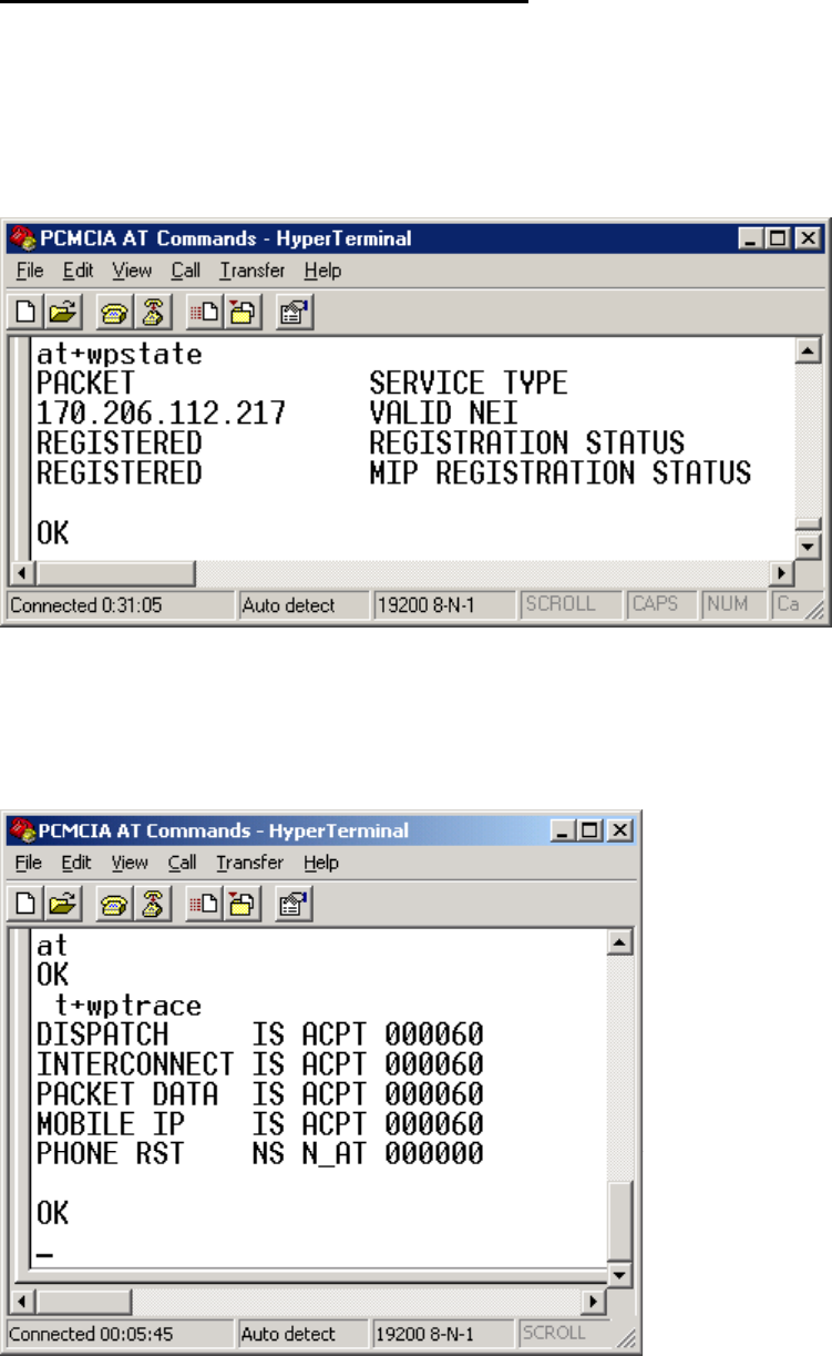
Packet Data Status Information Command
To check the current state of the iO1500R, use the Packet Data Status Information
command. This is the AT command to be used:
AT+wpstate
Below is what the iO1500R might respond with when this command is used:
AT+wptrace
Below is what the iO1500R might respond with when this command is used:
20/5/03 page 26 of 37
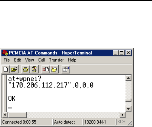
IP Address/ Network Entity Identifier (NEI) Command
To check the current IP address of the iO1500R node, as well as the Network Entity
Identifier (NEI), use the DTE IP Address query command as follows:
AT+wpnei?
Below is what the iO1500R might respond with when this command is used:
First the IP address is displayed in quotes, followed by the current NEI.
20/5/03 page 27 of 37

Summary Of AT Commands
This is a consolidated list of the AT commands mentioned in this document.
See the iDEN Mobile Subscriber DTE/DCE Interface for Data Services
68P81129E10-C for detailed AT command descriptions.
General AT Commands
Command Usage Remarks
AT AT Checks communication.
ATEx ATE0 or ATE1 Sets echo on or off.
AT&V AT&V Displays module parameters.
AT+IPR AT+IPR= baud rate Sets the baud rate of the module
User Image Profile Management Commands
Command Usage Remarks
ATz ATz0, ATz1, or ATz2 Sets the specified image as the active image.
AT&Wx AT&W0, 1, or 2. Writes active image to the specified profile.
Hayes Compatible Packet Data Commands
Command Usage Remarks
AT+ws45 AT+ws45=0 or 3 or 4 Selects the DTE side protocol stack.
AT+ws46 AT+ws45=23 or 24 Selects the carrier/network side stack.
ATd ATd <IP_address>..<port#> Tells module to originate a call.
Registration, Reset, and power off Commands
Command Usage Remarks
AT+wvreset AT+wvreset Resets the iO15 modem.
AT+wvmr AT+wvmr=”xxxx” (0000) Master Resets the iO15 modem.
AT+wvpo At+wvpo Software Powers Off the iO15 modem.
AT+WPDEREG AT+WPDEREG Forces modem to deregister.
AT+WPREG AT+WPREG Forces modem to register
AT+trace AT+trace Service Status Log
SIM card management Commands
Command Usage Remarks
AT+wvsim +wvsim=”<SIM PIN>” Unlocks the SIM card.
AT+wvsim +wvsim? Query SIM status.
AT+wvsim +wvsim=? Range.
AT+wvsimtgl +wvsimtgl=1,”<SIM PIN>” Enables SIM PIN mechanism
AT+wvsimtgl +wvsimtgl=0,”<SIM PIN>” Disables SIM PIN mechanism
AT+wvsimtgl +wvsimtgl? Query SIM PIN mechanism status.
AT+wvsimtgl +wvsimtgl=? Range.
20/5/03 page 28 of 37

Network Status Commands
Command Usage Remarks
AT+WS53? AT+WS53? Check Signal Quality.
AT+WS50? AT+WS53? Check Signal Strength.
AT+WPSTATE AT+WPSTATE Check mobile IP registration.
AT+WPNEI? AT+WPNEI? DTE IP Address
20/5/03 page 29 of 37

Appendix A: Requirements For FCC Testing
The iO1500R has a built in testing software mode called “BERBUG” that is
preferable for FCC testing. This mode, which will be activated by Motorola, allows
the engineers to perform FCC tests.
In BERBUG mode, the developers can communicate with the iO1500R using
Windows HyperTerm program, and prewritten scripts provided by Motorola. These
scripts are simple text files (.TXT format), which are sent to the iO1500R module via
a PC COM port using Hypeterm. The engineers performing the tests for FCC should
use these scripts then RESET the module after each test. The developer should make
sure the iO1500R OEM Module is connected to a serial com port on a PC.
It is recommended that development engineers who will be taking data for FCC
approval use the Motorola iO1500R FCC filing as a guide. This filing can be viewed
online at the FCC’s web site. These instructions show how to access the filing:
Preferred method of accessing the iO1500R FCC filing
If you are viewing this guide online, simply click on this link below to access the
iO1500R FCC filing:
http://gullfoss2.fcc.gov/cgi-
bin/ws.exe/prod/oet/forms/reports/Search_Form.hts?mode=Edit&form=Exhibits&app
lication_id=92993&fcc_id=AZ492FT5826
Alternate method of accessing the iO1500R FCC filing
If you cannot access the iO1500R FCC filing using the above method, try this manual
method that will also take you to the filing.
1) On the Internet, browse to the FCC search site: www.fcc.gov/oet/fccid/
2) Two pieces of information are needed here to locate the filing. In the field
marked “Grantee Code”, enter this value: AZ4.
3) In the field marked Equipment Product Code, enter this value: 92FT5826.
4) Hit the “Start Search” button. The results page shows a table listing the
different versions of the filing that were submitted.
5) In the query results, click the icon under “Display Exhibits”. This brings up a
list of all the exhibits (documentation, test results, charts, graphs, test
methodology, etc.) that were submitted for this filing, in PDF format.
Which files to use
The files that are the most useful are the Test Reports and also the Test Setup files.
Specifically, look for Measured Data A, Measured Data B, Measured Data C, and
Test Setup Photos, which also contain test procedures.
20/5/03 page 30 of 37

The following tests should be performed on the iO1500R by qualified personnel
to submit for FCC type approval of the product that will contain the iO1500R:
• Conducted Emissions and Radiated Emissions Transmit Mode
The iO1500R is cabled to a spectrum analyzer, looking for spurious emissions.
Data should be taken at 3 TX frequencies: low, mid and high, with the iO1500R
set to continuous transmit. Data should be taken from the 10th harmonic, down to
lowest fundamental frequency in the unit. The low, mid, and high frequencies
used are: 806.0625 MHz, 813.5625 MHz, and 824.9875 MHz. Script files are
provided to automate the FCC tests using Hyperterm to set the iO1500R to the
proper transmit mode. See the following pages for directions.
• Conducted Antenna Output Jack Receive Mode – Typically used for Canada
filings. A spectrum analyzer is cabled to the iO1500R. Look on the spectrum
analyzer for spurious power out of receive band. Data should be taken at 2
frequencies, low and high, and the iO1500R set to continuous receive. Script files
are provided to automate the FCC tests using Hyperterm to set the iO1500R to the
proper receive mode. See the following pages for directions.
Receiver Spurious Radiation – The iO1500R should not be registered to a cell
tower during the test. Ensure that the iO1500R module is in continuous searching
mode, with no timeout set. A dummy load should be used to ensure that the
iO1500R does not find any carrier. Canada requires this data to be taken, the U.S.
does not. Data should be taken up to the third harmonic, at three frequencies.
Script files are provided to automate the FCC tests using Hyperterm to set the
iO1500R to the proper receive mode. See the following pages for directions.
• Occupied Bandwidth Pursuant to 47 CFR 2.989 - Tested at 3 different data
transmit modes, measured both at high and low power output. Script files are
provided to automate the FCC tests using Hyperterm to set the iO1500R to the
proper transmit mode for occupied bandwidth. See the following pages for
directions.
• ERP- Effective Radiated Power, CW test method.
Instructions for these modes appear on the following pages. These FCC files will be
emailed on an as needed basis to developers who purchase the special FCC version of
the iO1500R with the FCC testing software installed. These FCC script files can be
downloaded directly from the iDEN Developer Program web site at
http://www.motorola.com/idendev/. The developer should load all the FCC script
files into a folder on the PC to be used with testing.
20/5/03 page 31 of 37
Conducted Emissions & Radiated Emissions Transmit Mode Tests
Step 1: Copy the Hyperterm file called “iO1500R FCC Testing.HT” to the Windows
desktop. This file must be used to open Hyperterm, as it automatically sets up several
paramters like baud rate and com port to allow Hyperterm to correctly talk to the
iO1500R. Double clicking this icon opens Hyperterm to use COM1. Also, copy all
the FCC script files into a folder on the PC.
For Radiated Transmit tests, use a 50 ohm RF dummy load.
For Conducted Transmit tests, just connect a cable to the antenna port.
Step 2: Connect the product containing the iO1500R with FCC testing code to the
COM1 port of the computer. Since the iO1500R with FCC software will
communicate with the PC using RS232, the RS232 lines on the iO1500R should be
made available to the external housing of the developer’s product by way of a
connector.
Step 3: Power up the iO1500R. The Hyperterm window should show the software
initializing on the module with a copyright statement, version information, then
should present the user with a prompt that looks like this:
BERBUG>
Step 4: The module is now ready to be placed in Transmit mode. This will be
accomplished by browsing to the folder where the FCC script files were placed,
choosing the proper script file, and sending it to the module. In Hyperterm, on the top
menu line, choose:
Transfer > Send Text File > FCC_TX_806.0625.txt
This file is used for Conducted or Radiated Transmit Testing at 806.0625 MHz.
Step 5: As the script is sent to the iO1500R, Hyperterm lists the commands sent:
BERBUG> tx freq 806.0625
BERBUG> tx pseudo
BERBUG> train 200
BERBUG> mode tx
BERBUG>
Step 6: The transmitter is now on. When testing is completed, the transmitter of the
iO1500R module should be turned off with the following command in Hyperterm:
BERBUG> mode idle
To prepare for the next data point, the iO1500R module should be reset or
power cycled to start with a clean slate. Use this command to reset the iO1500R
module:
BERBUG> reset
Step 7: Repeat Steps 4 - 6 with the other 2 files for Conducted Transmit Testing:
20/5/03 page 32 of 37
FCC_TX_813.5625.txt and FCC_TX_824.9875.txt.
Conducted Antenna Output Jack Receive Mode
Step 1: Connect the product containing the iO1500R with FCC testing code to the
COM1 port of the computer.
Step 2: Power up the iO1500R. The Hyperterm window should show the software
initializing on the module with a copyright statement, version information, then
should present the user with a prompt that looks like this:
BERBUG>
Step 3: The module is now ready to be placed in Receive mode. This will be
accomplished by browsing to the folder where the FCC RX script files were placed,
choosing the proper script file, and sending it to the module. In Hyperterm, on the top
menu line, choose:
Transfer > Send Text File > FCC_RX_851.0125.txt
This file is used for Conducted or Radiated Receive Testing 851.0125 MHz.
Step 4: The script commands are sent to the iO1500R and the Hyperterm screen will
display the following information:
BERBUG> rx freq 851.0125
BERBUG> rx static
BERBUG> mode rx
BERBUG>
DSP has lost sync!
The module will respond with “DSP has lost SYNC!” since there is no signal for the
module to receive. This is normal and hitting the ”Enter” or “Return” key will return
the “BERBUG>” prompt and the iO1500R will be in constant receive mode.
Step 6: When testing is completed, the receiver of the iO1500R module should be
turned off with the following command in Hyperterm:
BERBUG> mode idle
To prepare for the next data point, the iO1500R module should be reset or
power cycled to start with a clean slate. Use this command to reset the iO1500R
module:
BERBUG> reset
Step 6: Repeat Steps 3 - 5 with the other 2 files for Conducted Receive Testing:
FCC_RX_858.5625.txt and FCC_RX_869.9875.txt.
20/5/03 page 33 of 37

Receiver Spurious Radiation Pursuant to 47 CFR 15.109 (a), (f)
Step 1: Connect the product containing the iO1500R with FCC testing code to the
COM1 port of the computer.
Step 2: Power up the iO1500R. The Hyperterm window should show the software
initializing on the module with a copyright statement, version information, then
should present the user with a prompt that looks like this:
BERBUG>
Step 3: The module is now ready to be placed in Receive mode. This will be
accomplished by browsing to the folder where the FCC RX script files were placed,
choosing the proper script file, and sending it to the module. In Hyperterm, on the top
menu line, choose:
Transfer > Send Text File > FCC_RX_851.0125.txt
This file is used for Conducted or Radiated Receive Testing 851.0125 MHz.
Step 4: The scipt commands are sent to the iO1500R and the Hyperterm screen will
display the following information:
BERBUG> rx freq 851.0125
BERBUG> rx static
BERBUG> mode rx
BERBUG>
DSP has lost sync!
The module will respond with “DSP has lost SYNC!” since there is no signal for the
module to receive. This is normal and hitting the ”Enter” or “Return” key will return
the “BERBUG>” prompt and the iO1500R will be in constant receive mode.
Step 6: When testing is completed, the receiver of the iO1500R module should be
turned off with the following command in Hyperterm:
BERBUG> mode idle
To prepare for the next data point, the iO1500R module should be reset or
power cycled to start with a clean slate. Use this command to reset the iO1500R
module:
BERBUG> reset
Step 6: Repeat Steps 3 - 5 with the other 2 files for Conducted Receive Testing:
FCC_RX_858.5625.txt and FCC_RX_869.9875.txt.
20/5/03 page 34 of 37

Occupied Bandwidth Pursuant to 47 CFR 2.989
Occupied bandwidth must be tested at 3 different data transmit modes, measured both
at high and low power output. The transmit modes are 16QAM, 64 QAM, and QPSK,
which is also known as 4 QAM.
Steps for High Power 16 QAM Transmit mode
Step 1: Connect the product containing the iO1500R with FCC testing code to the
COM1 port of the computer.
Step 2: Power up the iO1500R. The Hyperterm window should show the software
initializing on the module with a copyright statement, version information, then
should present the user with a prompt that looks like this:
BERBUG>
Step 3: The module is now ready to be placed in 16 QAM Transmit mode. This will
be accomplished by browsing to the folder where the FCC RX script files were
placed, choosing the proper script file, and sending it to the module. In Hyperterm,
on the top menu line, choose:
Transfer > Send Text File > Occupied_BW_16QAM_High_Power.txt
Step 4: As the script is sent to the iO1500R, Hyperterm lists the commands sent:
BERBUG> tx freq 824.9875
BERBUG> tx pseudo
BERBUG> train 200
BERBUG> mode tx
BERBUG>
Step 5: The transmitter is now on in 16 QAM, with data scrolling up the screen.
When testing is completed, the transmitter of the iO1500R module should be turned
off with the following command in Hyperterm:
BERBUG> mode idle The data is still scrolling by, but just keep typing and it will
work. The data will still scroll until the next reset command.
To prepare for the next data point, the iO1500R module should be reset or
power cycled to start with a clean slate. Use this command to reset the iO1500R
module:
BERBUG> reset
Step 6: Repeat Steps 3 - 5 with the file for Low Power 16 QAM Occupied Bandwidth:
Occupied_BW_16QAM_Low_Power.txt
20/5/03 page 35 of 37

Occupied Bandwidth (continued)
Steps for High Power 64 QAM Transmit mode
Step 1: Connect the product containing the iO1500R with FCC testing code to the
COM1 port of the computer.
Step 2: Power up the iO1500R. The Hyperterm window should show the software
initializing on the module with a copyright statement, version information, then
should present the user with a prompt that looks like this:
BERBUG>
Step 3: The module is now ready to be placed in 64 QAM Transmit mode. This will
be accomplished by browsing to the folder where the FCC RX script files were
placed, choosing the proper script file, and sending it to the module. In Hyperterm,
on the top menu line, choose:
Transfer > Send Text File > Occupied_BW_64_QAM_High_Power.txt
Step 4: As the script is sent to the iO1500R, Hyperterm lists the commands sent:
BERBUG> tx freq 824.9875
BERBUG> tx pseudo
BERBUG> train 200
BERBUG> qam 64
BERBUG> frame pda
BERBUG> dcap len 0
BERBUG> dcap bandm db6db6
BERBUG> mode tx
Step 5: The transmitter is now on in QAM 64 mode, with data scrolling up the
screen. When testing is completed, the transmitter of the iO1500R module should be
turned off with the following command in Hyperterm:
BERBUG> mode idle The data is still scrolling by, but just keep typing and it will
work. The data will still scroll until the next reset command.
To prepare for the next data point, the iO1500R module should be reset or
power cycled to start with a clean slate. Use this command to reset the iO1500R
module:
BERBUG> reset
Step 6: Repeat Steps 3 - 5 with the file for Low Power 64 QAM Occupied
Bandwidth:
Occupied_BW_64_QAM_Low_Power.txt
20/5/03 page 36 of 37

Occupied Bandwidth (continued)
Steps for High Power CPSK (4 QAM) Transmit mode
Step 1: Connect the product containing the iO1500R with FCC testing code to the
COM1 port of the computer.
Step 2: Power up the iO1500R. The Hyperterm window should show the software
initializing on the module with a copyright statement, version information, then
should present the user with a prompt that looks like this:
BERBUG>
Step 3: The module is now ready to be placed in CPSK Transmit mode. This will be
accomplished by browsing to the folder where the FCC RX script files were placed,
choosing the proper script file, and sending it to the module. In Hyperterm, on the top
menu line, choose:
Transfer > Send Text File > Occupied_BW_QPSK_High_Power.txt
Step 4: As the script is sent to the iO1500R, Hyperterm lists the commands sent:
BERBUG> tx freq 824.9875
BERBUG> tx pseudo
BERBUG> train 200
BERBUG> qam 4
BERBUG> frame pda
BERBUG> dcap len 0
BERBUG> dcap bandm db6db6
BERBUG> mode tx
Step 5: The transmitter is now on in QPSK mode, with data scrolling up the screen.
When testing is completed, the transmitter of the iO1500R module should be turned
off with the following command in Hyperterm:
BERBUG> mode idle The data is still scrolling by, but just keep typing and it will
work. The data will still scroll until the next reset command.
To prepare for the next data point, the iO1500R module should be reset or
power cycled to start with a clean slate. Use this command to reset the iO1500R
module:
BERBUG> reset
Step 6: Repeat Steps 3 - 5 with the file for Low Power QPSK Occupied Bandwidth:
Occupied_BW_QPSK_Low_Power.txt
20/5/03 page 37 of 37