Motorola Solutions 92FT7045 LTE Vehicular Subscriber Modem User Manual LTE VSM Installation Guide
Motorola Solutions, Inc. LTE Vehicular Subscriber Modem LTE VSM Installation Guide
Contents
- 1. Ex 8 Users Manual
- 2. Ex 8a RF Safety Booklet
- 3. Ex8 Users Manual
- 4. Ex8a RF Safety Booklet
- 5. FT7045 Ex8b amended RF Safety Guide
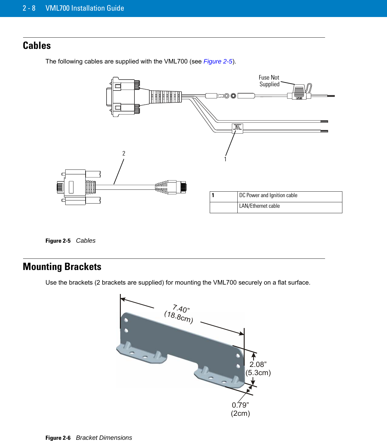
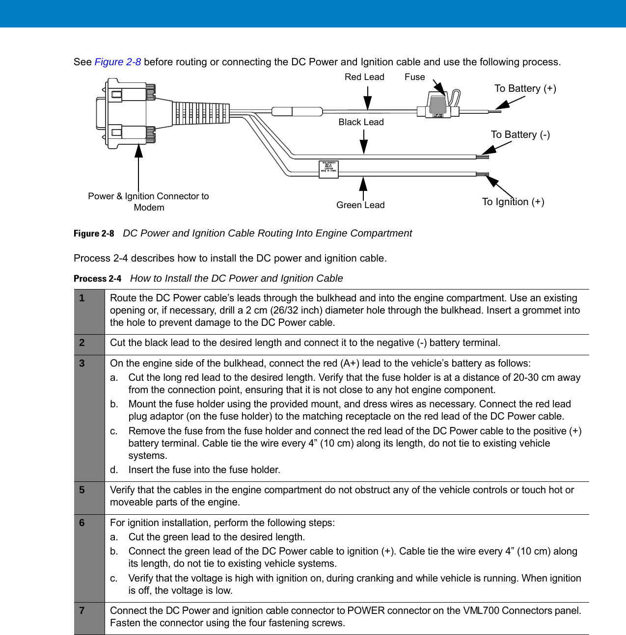
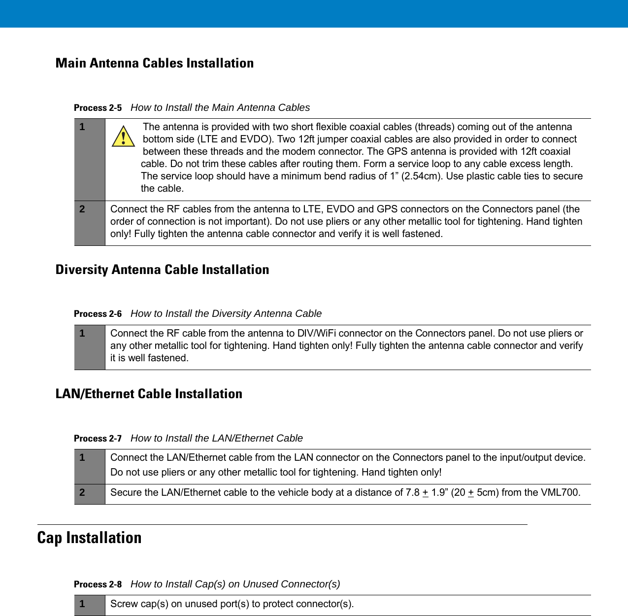
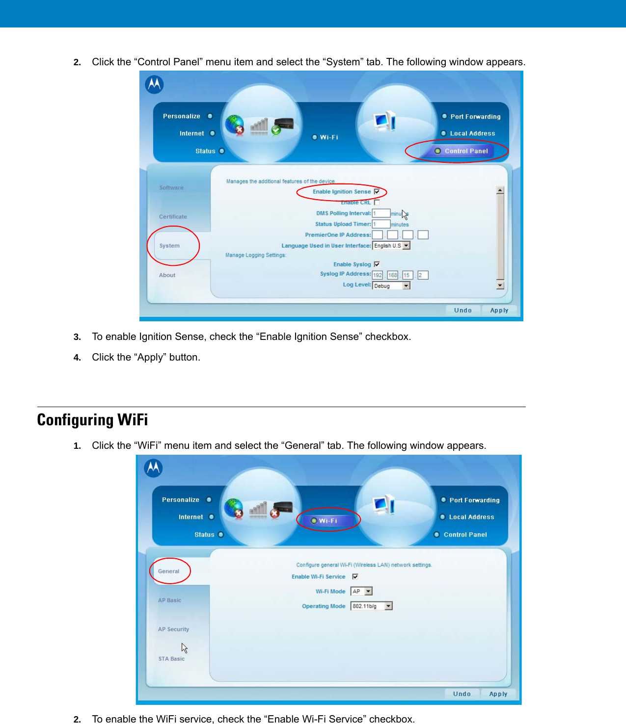
Ex 8 Users Manual


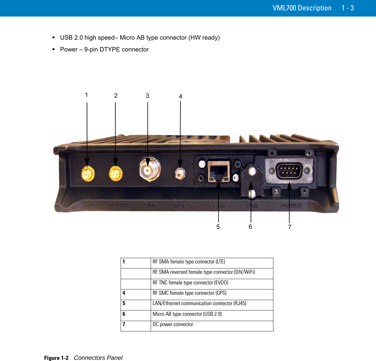


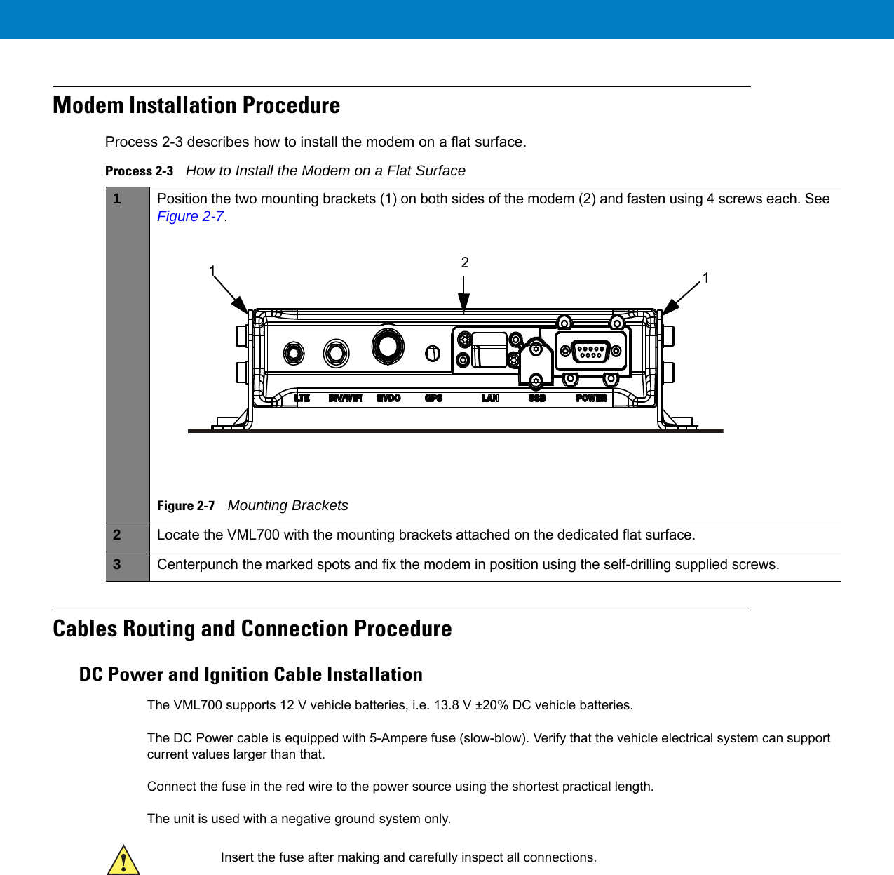


Ex8 Users Manual