Motorola Solutions 92FT7045 LTE Vehicular Subscriber Modem User Manual LTE VSM Installation Guide
Motorola Solutions, Inc. LTE Vehicular Subscriber Modem LTE VSM Installation Guide
Contents
- 1. Ex 8 Users Manual
- 2. Ex 8a RF Safety Booklet
- 3. Ex8 Users Manual
- 4. Ex8a RF Safety Booklet
- 5. FT7045 Ex8b amended RF Safety Guide
Ex 8 Users Manual

VML700 - LTE Vehicular Subscriber
Modem (VSM)
Installation Guide

VML700 - LTE VSM
Installation Guide
6802987C90
Revision A
June 2011
ii VML700 Installation Guide
© 2011 by Motorola Solutions, Inc. All rights reserved.
No part of this publication may be reproduced or used in any form, or by any electrical or mechanical means,
without permission in writing from Motorola. This includes electronic or mechanical means, such as
photocopying, recording, or information storage and retrieval systems. The material in this manual is subject to
change without notice.
The software is provided strictly on an “as is” basis. All software, including firmware, furnished to the user is on
a licensed basis. Motorola grants to the user a non-transferable and non-exclusive license to use each
software or firmware program delivered hereunder (licensed program). Except as noted below, such license
may not be assigned, sublicensed, or otherwise transferred by the user without prior written consent of
Motorola. No right to copy a licensed program in whole or in part is granted, except as permitted under
copyright law. The user shall not modify, merge, or incorporate any form or portion of a licensed program with
other program material, create a derivative work from a licensed program, or use a licensed program in a
network without written permission from Motorola. The user agrees to maintain Motorola’s copyright notice on
the licensed programs delivered hereunder, and to include the same on any authorized copies it makes, in
whole or in part. The user agrees not to decompile, disassemble, decode, or reverse engineer any licensed
program delivered to the user or any portion thereof.
Motorola reserves the right to make changes to any software or product to improve reliability, function, or
design.
Motorola does not assume any product liability arising out of, or in connection with, the application or use of
any product, circuit, or application described herein.
No license is granted, either expressly or by implication, estoppel, or otherwise under any Motorola, Inc.,
intellectual property rights. An implied license only exists for equipment, circuits, and subsystems contained in
Motorola products.
MOTOROLA SOLUTIONS and the Stylized M Logo and Symbol and the Symbol logo are registered in the US
Patent & Trademark Office. Bluetooth is a registered trademark of Bluetooth SIG. Microsoft, Windows and
ActiveSync are either registered trademarks or trademarks of Microsoft Corporation. All other product or
service names are the property of their respective owners.
Patents
This product is covered by one or more of the patents listed on the website:
http://www.motorola.com/enterprisemobility/patents.
Warranty
For the complete Motorola hardware product warranty statement, go to:
http://www.motorola.com/enterprisemobility/warranty.
Legal Notice
The VML700 OSS legal notice may be found in the root directory of the LTE VSM Software CD (P/N
82013113001).

Revision History
Changes to the original manual are listed below:
Change Date Description
A Initial release

iv VML700 Installation Guide

Table of Contents v
Patents........................................................................................................................... ii
Warranty ........................................................................................................................ ii
Legal Notice ................................................................................................................... ii
Revision History ............................................................................................................. iii
About This Guide
Introduction .................................................................................................................... vii
Configurations ................................................................................................................ vii
Chapter Descriptions ..................................................................................................... viii
Notational Conventions.................................................................................................. ix
Related Documents ....................................................................................................... ix
Service Information ........................................................................................................ ix
Safety............................................................................................................................. x
FCC Interference ........................................................................................................... x
Chapter 1: VML700 Description
The VML700 Unit .......................................................................................................... 1-1
Modem .......................................................................................................................... 1-2
Connectors Panel ......................................................................................................... 1-2
LED Indicator Panel with On/Off Button and SIM Card Door ........................................ 1-4
LED Indicators Functions .............................................................................................. 1-5
Control .......................................................................................................................... 1-5
SIM Card........................................................................................................................ 5
Chapter 2: Installation
Unpacking and Inspecting the Shipment ...................................................................... 2-1
Safety and General Information .................................................................................... 2-1
Planning the Installation ................................................................................................ 2-3
Installation Constraints ............................................................................................ 2-3
Cables Routing ........................................................................................................ 2-4
Drilling Holes ........................................................................................................... 2-4
Tools and Equipment .............................................................................................. 2-5
Antennas ....................................................................................................................... 2-6
Main Antenna .......................................................................................................... 2-6
Diversity Antenna .................................................................................................... 2-7
Cables ........................................................................................................................... 2-7
Mounting Brackets ........................................................................................................ 2-8
Modem Installation Process .......................................................................................... 2-8
Antennas Mounting ....................................................................................................... 2-9
Special Antennas Installation Considerations ......................................................... 2-9
Modem Installation Procedure ...................................................................................... 2-10
Cables Routing and Connection Procedure .................................................................. 2-10
DC Power and Ignition Cable Installation ................................................................ 2-10
Main Antenna Cables Installation ............................................................................ 2-12
Diversity Antenna Cable Installation ....................................................................... 2-12
LAN/Ethernet Cable Installation .............................................................................. 2-12
Cap Installation ............................................................................................................. 2-12

Table of Contents vi
Chapter 3: Configuring and Monitoring the VML700
Introduction ................................................................................................................... 3-1
Prior to Configuration .................................................................................................... 3-1
The Configuration Wizard ............................................................................................. 3-2
Changing the Login Password ................................................................................ 3-3
Configuring the LTE VML700 Time Zone ................................................................ 3-3
Configuring the VML700 Security ........................................................................... 3-4
Configuring the Ignition Switch ..................................................................................... 3-4
Configuring WiFi ........................................................................................................... 3-5
Monitoring the VML700 Operation ................................................................................ 3-6
Chapter 4: Troubleshooting
Introduction ................................................................................................................... 4-1
Troubleshooting ............................................................................................................ 4-1
Chapter 5: Using the VML700
General ......................................................................................................................... 5-1
Appendix A: Specifications
Physical ......................................................................................................................... A-1
Communication Ports .............................................................................................. A-1
RF Ports .................................................................................................................. A-1
Power Ports ............................................................................................................. A-1
LEDs ....................................................................................................................... A-2
Operating Temperature ........................................................................................... A-2
Power ...................................................................................................................... A-2
Main Antenna .......................................................................................................... A-3
Diversity Antenna .................................................................................................... A-3
Communication Channel Packet Error Rate ........................................................... A-4
RF Characteristics ................................................................................................... A-4
Appendix B: Reference
Replacement Parts ....................................................................................................... B-1
Replacement Parts List ........................................................................................... B-1
Kit Replacement Parts List ...................................................................................... B-2

About This Guide
Introduction
The VML700 LTE VSM Installation Guide provides general instructions for installing, setting up, operating, and
troubleshooting the VML700.
NOTE The names LTE VSM and VML700 are interchangeable and they are both used in this manual.
Configurations
This guide includes the following configuration:
•
F4080A model VML700

Chapter Descriptions
Topics covered in this guide are as follows:
•
Chapter 1, VML700 Description provides the product overview.
•
Chapter 2, Installation provides unpacking instructions and all required procedures for installing the VML700.
•
Chapter 3, Configuring and Monitoring the VML700 provides the procedures that enable configuring the
VML700 for best operation.
•
Chapter 4, Troubleshooting provides details regarding possible malfunctions that may occur after first time
installation of the VML700, their probable cause and the recommended corrective actions.
•
Chapter 5, Using the VML700 provides general information regarding the use of the VML700.

About This Guide vi
The following conventions are used in this document:
•
Italics are used to highlight the following:
•Chapters and sections in this and related documents
•Dialog box, window and screen names
•Drop-down list and list box names
•Check box and radio button names
•
Bold text is used to highlight the following:
•Key names on a keypad
•Button names on a screen.
•
bullets (•) indicate:
•Action items
•Lists of alternatives
•Lists of required steps that are not necessarily sequential
•
Sequential lists (e.g., those that describe step-by-step procedures) appear as numbered lists.
Related Documents
•
VML700 LTE VSM Basic Service Manual, p/n 6802988C02
Service Information
If you have a problem with your equipment, contact Motorola Enterprise Mobility support for your region. Contact
information is available at: http://www.motorola.com/enterprisemobility/contactsupport.
When contacting Enterprise Mobility support, please have the following information available:
•
Serial number of the unit
•
Model number or product name
•
Software type and version number
Motorola responds to calls by e-mail, telephone or fax within the time limits set forth in service agreements.
If your problem cannot be solved by Motorola Enterprise Mobility Support, you may need to return your equipment
for servicing and will be given specific directions. Motorola is not responsible for any damages incurred during
shipment if the approved shipping container is not used. Shipping the units improperly can possibly void the
warranty.
If you purchased your Enterprise Mobility business product from a Motorola business partner, please contact that
business partner for support.

Safety
Before installing/using this product, the installer/operator must be familiar with the RF energy awareness
information and operating instructions in the “Product Safety and RF Energy Exposure Booklet” enclosed with the
VML700 LTE VSM (Motorola Publication part number 6881095C99) to ensure compliance with Radio Frequency
(RF) energy exposure limits.
FCC Interference
This device complies with Part 15 of the FCC Rules. Operation is subject to the following two conditions:
(1) This device may not cause harmful interference.
(2) This device must accept any interference received, including interference that may cause undesired operation.
This Class A/B digital apparatus complies with Canada ICES-003.
Changes or modifications made to this product, not expressly approved by Motorola, will void the user's authority to
operate the equipment, per FCC Rule Part 15.21.


1 - 2 VML700 Installation Guide
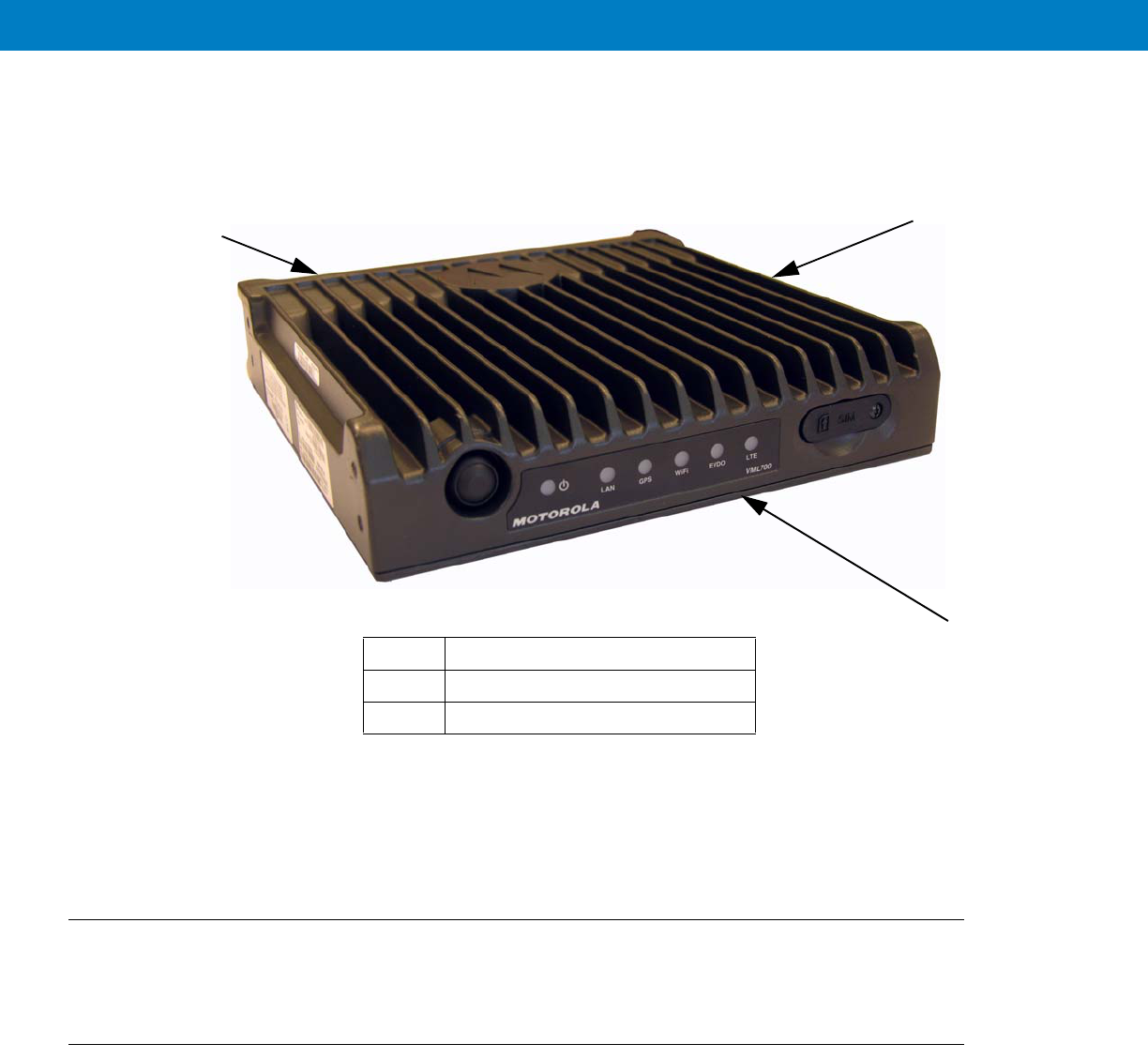
Figure 1-1
VML700 - General View
For detailed specifications of the VML700 unit, see Appendix A: Specifications.
Modem
The modem has a Connectors panel (back panel) and a LED Indicator panel with On/Off button (front panel).
Connectors Panel
The VML700 Connectors panel consist of the following (see Figure 1-2):
•
LTE Main Rx/Tx – SMA type connector
•
Diversity – LTE secondary Rx/EVDO secondary Rx/WiFi – reverse SMA type connector
•
EVDO Main Rx/Tx – TNC type connector
•
GPS – SMC type connector
•
LAN – Ethernet 10/100 – RJ45 type connector
1Modem
2LED Indicator Panel (Front Panel)
3Connectors Panel (Back Panel - not shown)
1
2
3
VML700 Description 1 - 3
•
USB 2.0 high speed– Micro AB type connector (HW ready)
•
Power – 9-pin DTYPE connector
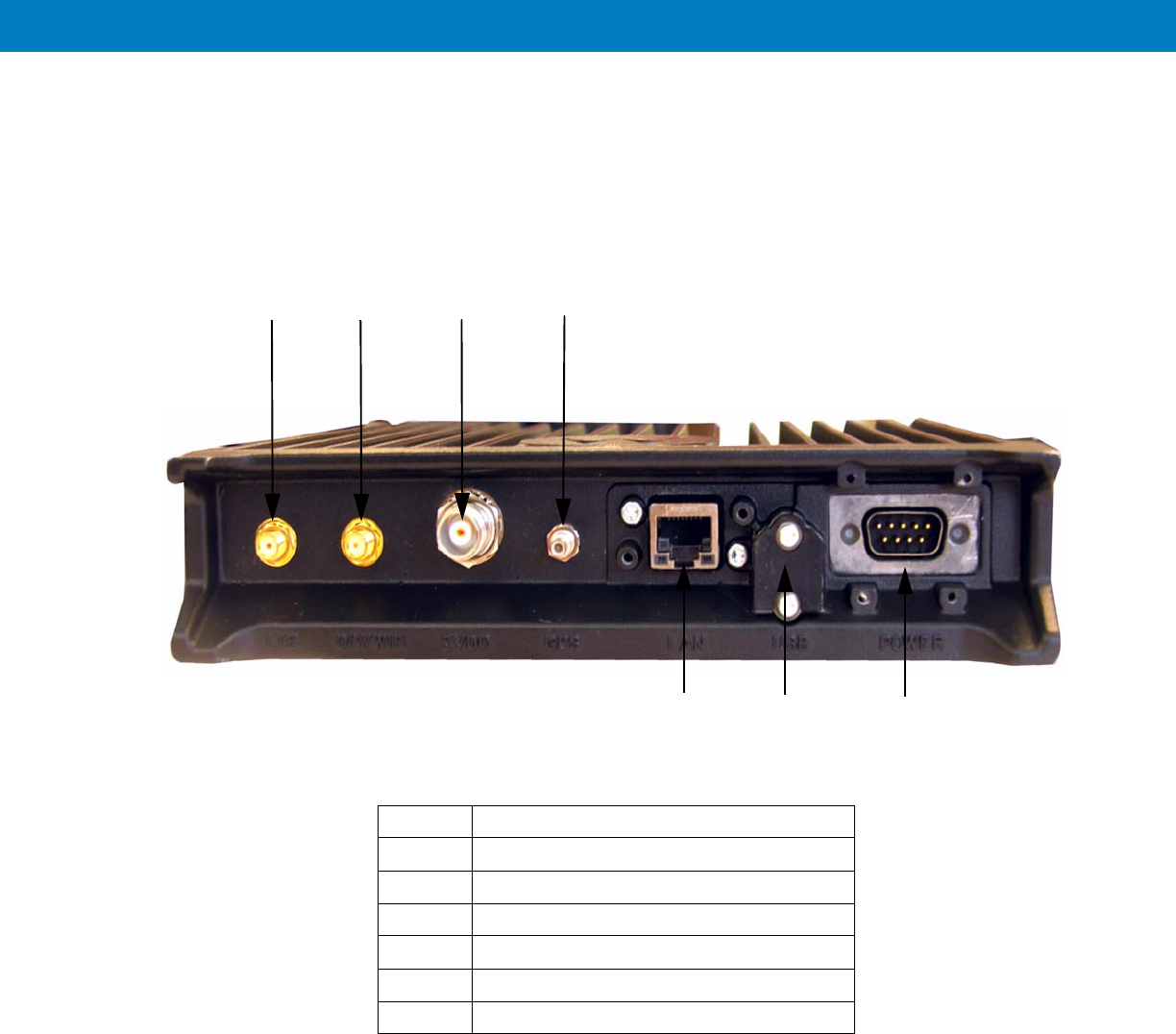
Figure 1-2
Connectors Panel
2
1
56
1RF SMA female type connector (LTE)
RF SMA reversed female type connector (DIV/WiFi)
RF TNC female type connector (EVDO)
4RF SMC female type connector (GPS)
5LAN/Ethernet communication connector (RJ45)
6Micro AB type connector (USB 2.0)
7DC power connector
34
7

1 - 5
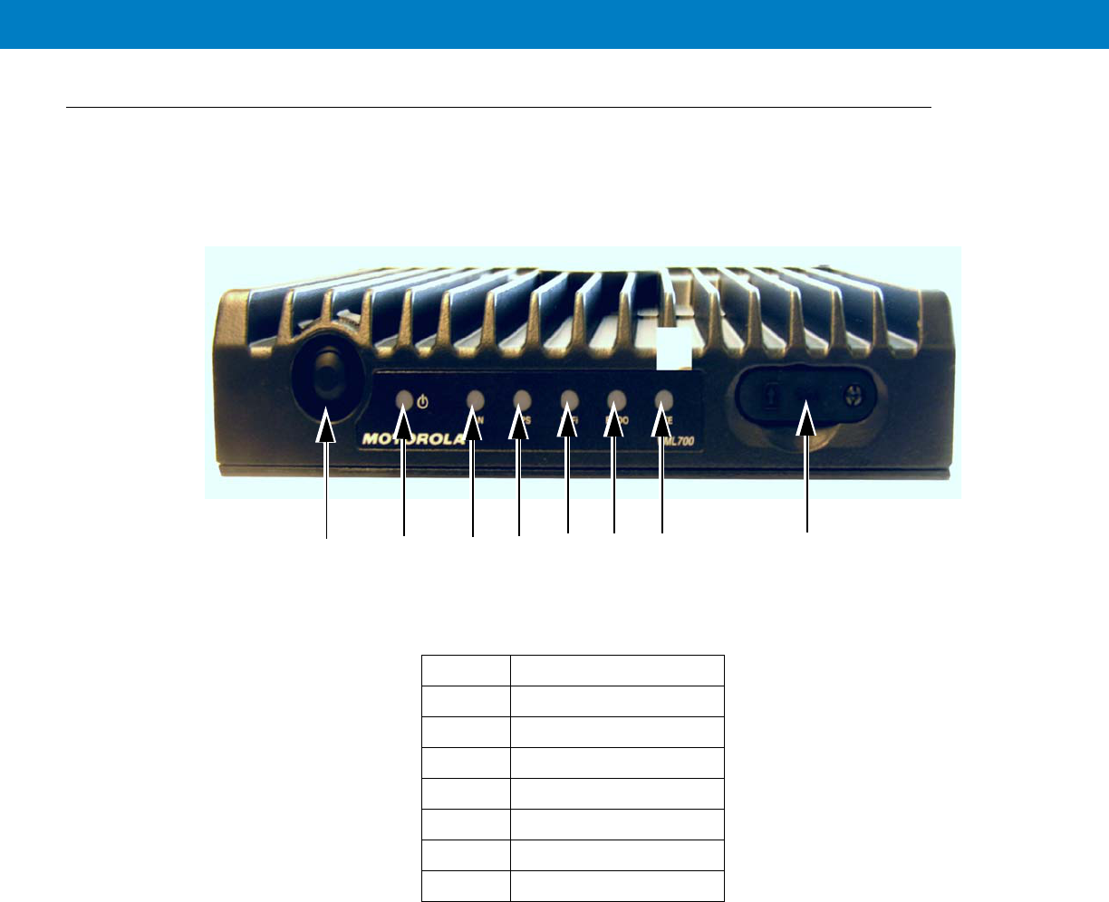
LED Indicators Functions
Table 1-1 describes the functions of the LED indicators on the VML700 front panel.
Control
The On/Off button is used to turn the VML700 On or Off.
SIM Card
A SIM is required for the operation of the modem.
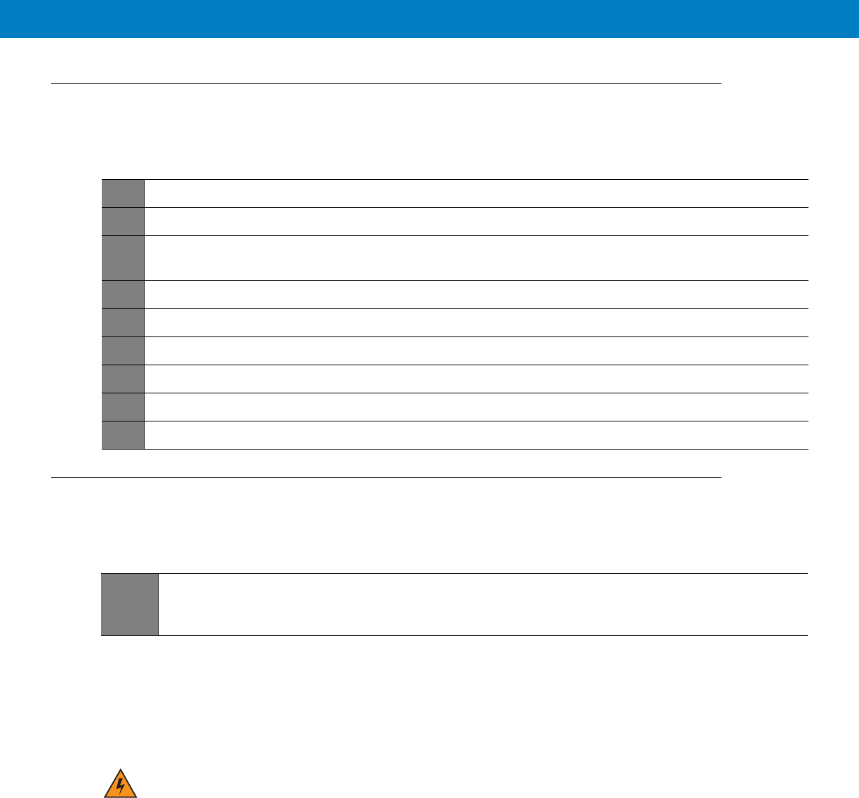
Table 1-1
LED Indicators Functions
LED Name Power LAN LTE EVDO WiFi GPS
LED Status
OFF Power off No link Off Off Off Off
Solid Green Power on Link is on Connected Connected Available Tracking
Blinking Green Powering up TX/RX
Activity
Connecting/
Registering
Connecting/
Registering
TX/RX Activity --
Solid Orange No Ignition
The user
turns the
power On
(power
button
pressed) but
ignition is off.
-- -- -- -- --
Blinking
Orange
-- -- Searching for
signal
Searching for
signal
-- Searching for
signal
Solid Red -- -- Problem/
Overheat
Problem/
Overheat
Problem/
Overheat
Problem
Blinking Red Standby
External
power is
connected to
the system.
-- -- -- -- --
Rapid Blinking
Red
Problem SIM door is
open

1 - 6 VML700 Installation Guide

Chapter 2 Installation
Unpacking and Inspecting the Shipment
Unpack your shipment and check the contents to ensure that you have received all the specified items.
Thoroughly inspect the equipment for shipping damage as soon as possible after delivery. Report any damage you
find to your Motorola Customer Service representative immediately.
Safety and General Information
A properly installed VML700 unit minimizes service calls. When mounting the VML700 unit components, consider
the following factors:
•
The mounting surface must have sufficient strength to support the equipment being mounted and to prevent
it from becoming loose over time.
•
Do not attach components to any part of the vehicle subjected to excessive vibration.
•
Do not mount the VML700 unit on a flat surface where the unit could become partially submersed in water.
•
The proposed location of the equipment being mounted or wires/cables attached must not interfere with
driver/passenger seating or leg space.
•
Select a location such that heat from the unit does not damage any wiring or any other plastic or
heat-sensitive parts of the automobile.
•
Use the supplied mounting hardware.
•
Leave sufficient space around the VML700 unit for air flow and installation.
•
Select a location that permits routing the cables as directly as possible.
•
Ensure that the cables are not stretched, and not subject to heat from the engine, transmission housing or
heating ducts.
•
Crimp connectors securely.
•
Do not run cables over sharp edges that may cause excessive wear or chaffing of the cable insulation.
•
Do not install components in locations where they may cause interference to the operation of the vehicle's
controls.

•
Only qualified personnel may install communication equipment.
•
Ensure secure tightening of cable connectors.
Install this product in a vehicle in accordance with the vehicle manufacturer’s guidelines and the instructions detailed in
this manual. Use only the Motorola parts specified in this manual.
Check the required mounting locations. It might be necessary to penetrate the bulkhead to reach the battery.
Before drilling commences, ensure cable clearance on the opposite side of the bulkhead and do not install the
vehicle’s Electronic Control Modules (ECM’s) on the opposite side of the bulkhead. Protect the cable where it
passes through the bulkhead by using a grommet or similar protective measures.
If necessary, contact the vehicle manufacturer for air bag information specific to the vehicle.
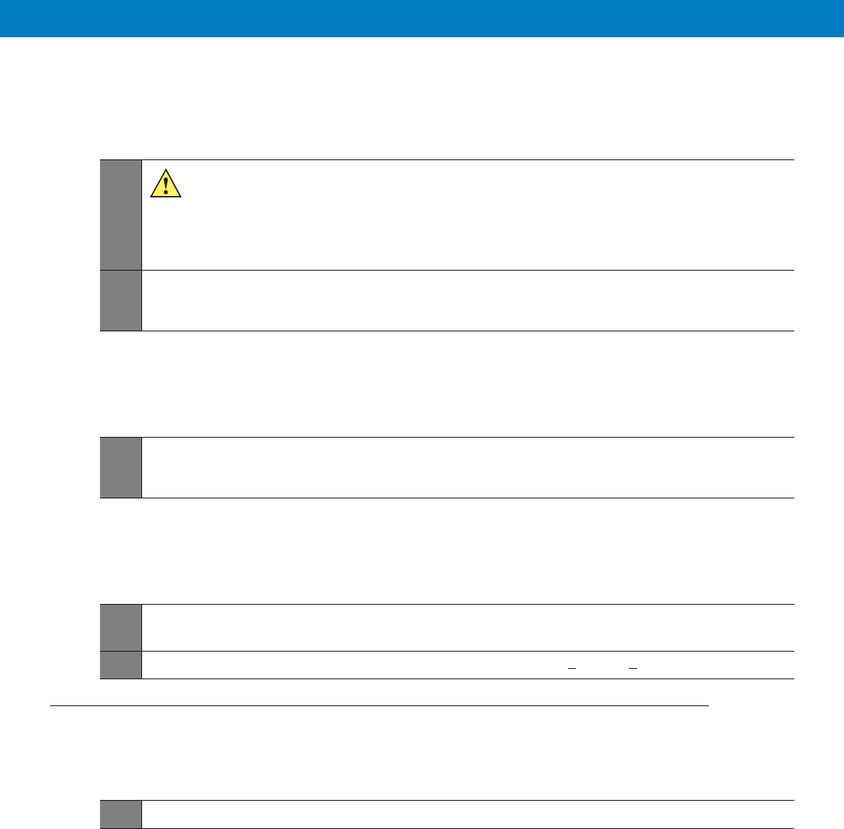
CAUTION Installing the VML700 at the end of the vehicle above the exhaust pipe may cause the VML700 to
overheat.
WARNING!VEHICLES EQUIPPED WITH AIR BAGS
An air bag inflates with great force. DO NOT place objects, including communications
equipment, in the area over the air bag or in the air bag deployment area. If the communication
equipment is improperly installed and the air bag inflates, this could cause serious injury.
WARNING!Verify that none of the vehicle’s systems are affected by use of the unit, e.g. cruise control,
ABS breaking, traction control, engine management, direction indicators, lights, etc.
WARNING!Use existing openings through the bulkhead to avoid drilling. If drilling is a must, verify not to
damage the Vehicle Electronic Control Modules (ECM’s), fuel pipes, brake pipes, and/or cable
looms.
WARNING!For vehicles equipped with electronic braking systems, see “ANTI-SKID BRAKING
PRECAUTIONS”, Motorola publication 68P81109E34.
It is mandatory that modems installed in vehicles fuelled by liquefied petroleum gas conform
to the National Fire Protection Association standard NFPA 58, which applies to vehicles with
a liquid propane (LP) gas container in the trunk or other sealed off space within the interior of
the vehicle. The NFPA 58 requires the following:
(1) The space in which the LP gas container and its fittings are located must be isolated by a
seal from the space containing modem equipment.
(2) Removable (outside) filling connections shall be used.
(3) The container space shall be vented to the outside.

Planning is the key to fast, easy and safe installation.
Installation Constraints
Refer to the Safety Instructions in “Product Safety and RF Energy Exposure Booklet for Mobile Two-Way Radios in
Vehicles or as Fixed Site Control” P/N 6881095C99.
The LTE VML700 must be installed in the car’s trunk, on the floor or the side walls (cooling fins facing up, or to the
side).
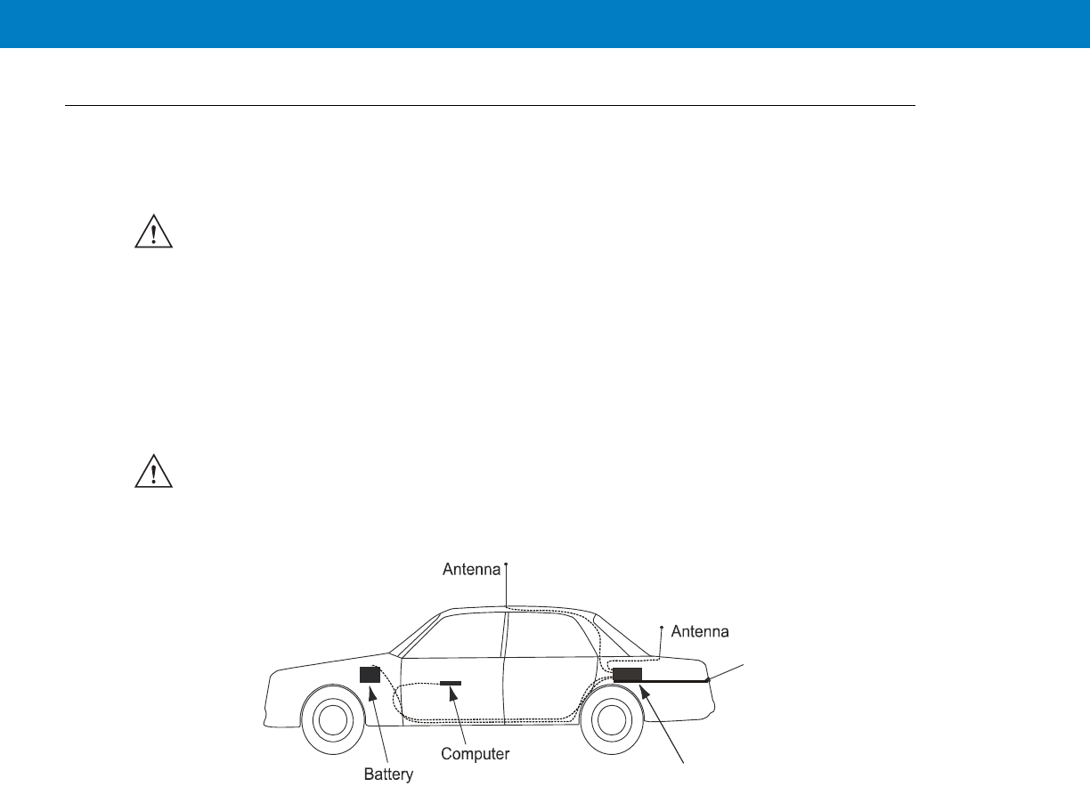
Figure 2-1 shows a typical VML700 installation in a car.
VML700 - Typical Car Installation
Before beginning the installation process make sure that the space available at the installation site is adequate for
the modem and its accessories. Each installation configuration requires a different area for mounting the modem
without obstruction.
When choosing a location, ensure easy installation and replacement of the unit.
MPORTANT Take the following points into consideration when selecting a location and planning the installation.
IMPORTANT The VML700 must not be installed with the cooling fins facing down. Failure to comply may cause
overheat problems and performance degradation.
Diversity
MAIN
VML700
Trunk Floor

Figure 2-2 gives the VML700 dimensions.
VML700 - Dimensions
Cables Routing
•
Before running a wire or drilling a hole, inspect the vehicle and determine how and where you intend to
mount the antenna, modem, and the input/output device.
•
Plan wire and cable routing to provide maximum protection from overheating, battery acid, moving parts and
sharp edges.
•
Keep cables away from ignition circuits to reduce noise pickup in the radio equipment.
•
Verify that the cables are of sufficient length. Do not connect two short lengths with a connector; doing so
results in signal loss. Refrain from loose excess in the cables, but leave enough slack to allow reconnection if
necessary.
•
Do not run cables externally or underneath floor mats.
•
Do not locate cables where the driver or passengers can kick them or where they can interfere with operation
of the driver’s foot pedals.
•
When routing the cable, refrain from creating sharp bends or kinks.
Drilling Holes
•
Where possible, use existing holes in the bulkhead, the trunk wall and the channels above or beneath the
doors. Run cables parallel to existing car cables if appropriate.
1
1.71”
4.35cm
8.07”
20.5cm
7.87”
20cm

•
If you must drill holes, verify not to damage other wiring, break lines or gas lines.
•
When drilling a hole in the roof, take care not to snag the roof liner.
•
To prevent rusting after drilling, remove all metal burrs and residue, and completely clean the area to ensure
the removal of all steel dust.
•
Insert rubber grommets in all drilled holes to protect cables.
Tools and Equipment
•
#2 Phillips screwdriver
•
Electrical drill and drill bit set
•
X-acto knife or equivalent
•
Wire stripper
•
Long nose pliers
•
Small side cutters
•
Crimping tool
•
Wrench set, including 8 mm for tray to unit attachment
•
3 mm Allen wrench set for unit to tray attachment
•
Soldering iron and solder
•
Electrical tape
Antennas
Main Antenna
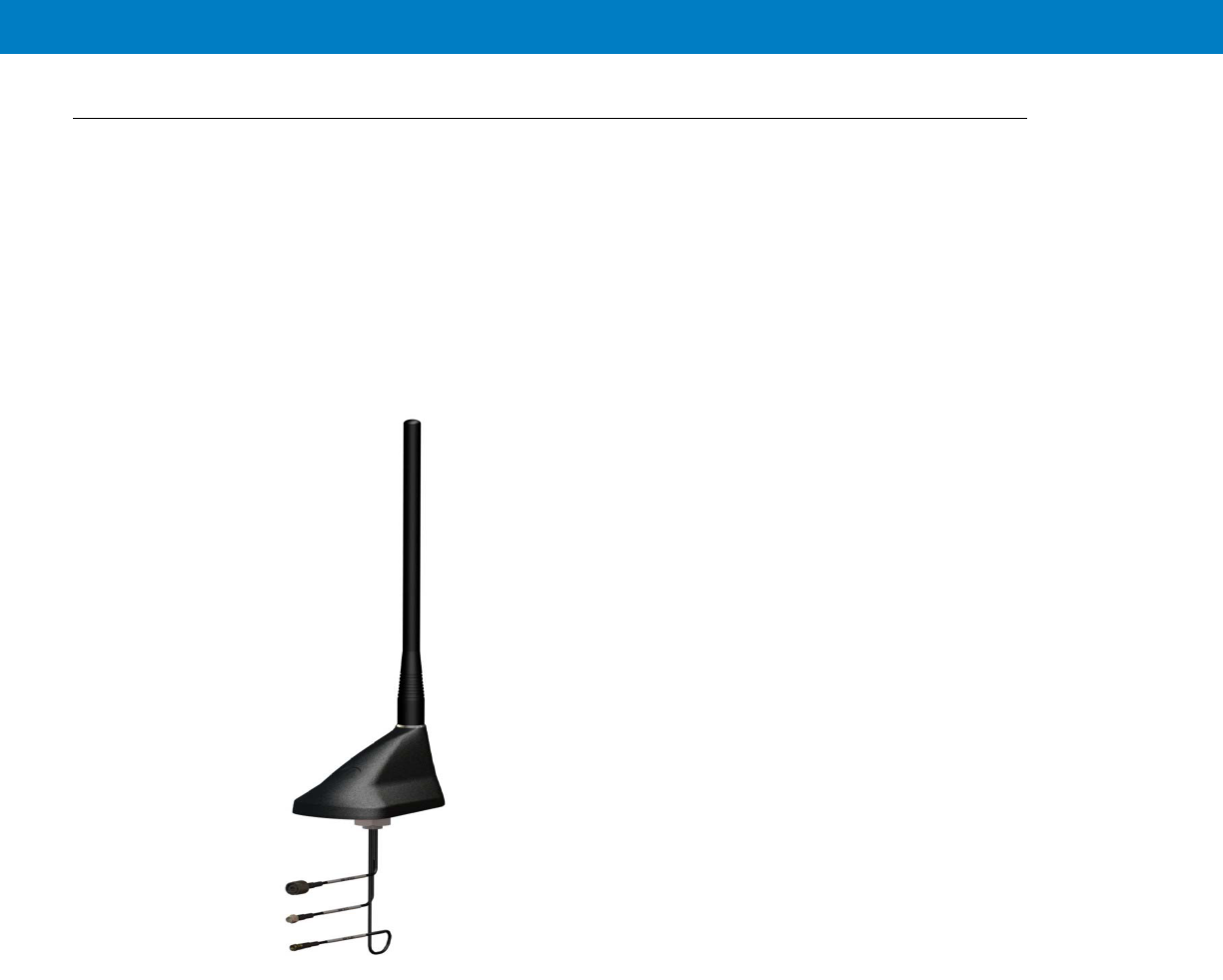
The main antenna is constructed of three antenna types (LTE, EVDO and GPS) on a single mount.
•
Kit No. FAF5266A
The antenna is provided with two short flexible coaxial cables (threads) coming out of the antenna bottom side
(LTE and EVDO). Two 12ft jumper coaxial cables are also provided in order to connect between these threads and
the modem connector. The GPS antenna is provided with 12ft coaxial cable. (see Figure 2-3).
Figure 2-3
Main Antenna
2 - 8 VML700 Installation Guide
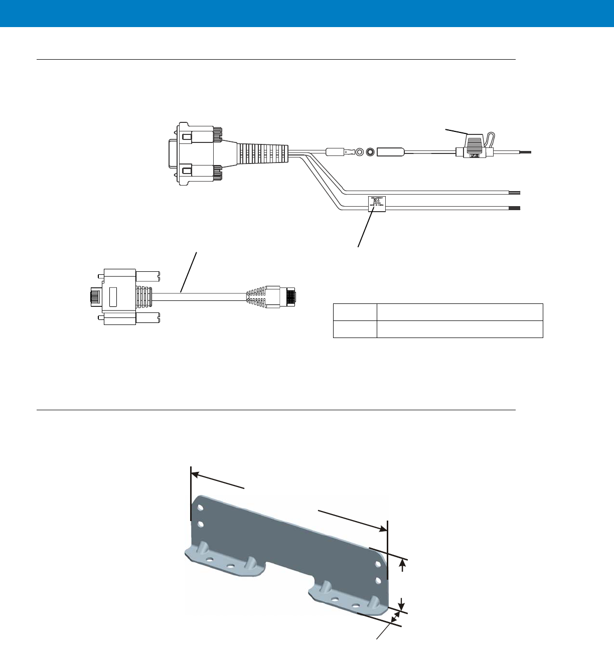
Cables
The following cables are supplied with the VML700 (see Figure 2-5).
Figure 2-5
Cables
Mounting Brackets
Use the brackets (2 brackets are supplied) for mounting the VML700 securely on a flat surface.
Figure 2-6
Bracket Dimensions
1DC Power and Ignition cable
LAN/Ethernet cable
1
Fuse Not
Supplied
2
7.40”
(18.8cm)
2.08”
(5.3cm)
0.79”
(2cm)
2 - 9
Process 2-1 describes the steps for the modem installation.
Process 2-2 gives general instructions for mounting the antennas.
Special Antennas Installation Considerations
General Antenna Installation Safety Considerations
Main Antenna
The main antenna must be installed on the vehicle’s roof, preferably in the center of it. For best performance, a minimum
distance of 36” (91.44cm) must be kept between this antenna and any other antenna.
Diversity Antenna
It is recommended that the Diversity Antenna will be installed on the vehicle’s trunk hood. For best performance, a
minimum distance of 36” (91.44cm) must be kept between this antenna and any PSNB antenna.
Process 2-1
Modem Installation Process
1
Ensure adequate space for the installation. (See Planning the Installation on page 2-3)
2
Install the antennas. (See Antennas Mounting on page 2-9).
3
Route the cables. (See Planning the Installation on page 2-3 and Cables Routing and Connection Procedure
on page 2-10).
4
Install the brackets and the unit. (See Modem Installation Procedure on page 2-10.).
5
Connect the DC Power and Ignition cable. (See DC Power and Ignition Cable Installation on page 2-10).
6
Connect the main antenna cables. (See Main Antenna Cables Installation on page 2-12).
7
Connect the Diversity/WiFi antenna cable. (See Diversity Antenna Cable Installation on page 2-12).
8
Connect the LAN/Ethernet cable. (See LAN/Ethernet Cable Installation on page 2-12).
9
Place caps on unused connector(s). (See Cap Installation on page 2-12).
Process 2-2
How to Mount the Antennas
1
Mount the antennas in accordance with the instructions provided with each antenna kit and with the
Product Safety and RF Energy Exposure Booklet for Mobile Two-Way Radios Installed in Vehicles or as
Fixed Site Control Stations (6881095C99) enclosed with the product.
The main and diversity antennas must be installed in a location that will ensure a distance of
at least 8” (20cm) between them and any bystander.

Modem Installation Procedure
Process 2-3 describes how to install the modem on a flat surface.
Cables Routing and Connection Procedure
DC Power and Ignition Cable Installation
The VML700 supports 12 V vehicle batteries, i.e. 13.8 V ±20% DC vehicle batteries.
The DC Power cable is equipped with 5-Ampere fuse (slow-blow). Verify that the vehicle electrical system can support
current values larger than that.
Connect the fuse in the red wire to the power source using the shortest practical length.
The unit is used with a negative ground system only.
Process 2-3
How to Install the Modem on a Flat Surface
1
Position the two mounting brackets (1) on both sides of the modem (2) and fasten using 4 screws each. See
Figure 2-7
.
Figure 2-7
Mounting Brackets
2
Locate the VML700 with the mounting brackets attached on the dedicated flat surface.
3
Centerpunch the marked spots and fix the modem in position using the self-drilling supplied screws.
1
12
Insert the fuse after making and carefully inspect all connections.

See Figure 2-8 before routing or connecting the DC Power and Ignition cable and use the following process.
Figure 2-8
DC Power and Ignition Cable Routing Into Engine Compartment
Process 2-4 describes how to install the DC power and ignition cable.
Process 2-4
How to Install the DC Power and Ignition Cable
1
Route the DC Power cable’s leads through the bulkhead and into the engine compartment. Use an existing
opening or, if necessary, drill a 2 cm (26/32 inch) diameter hole through the bulkhead. Insert a grommet into
the hole to prevent damage to the DC Power cable.
2
Cut the black lead to the desired length and connect it to the negative (-) battery terminal.
3
On the engine side of the bulkhead, connect the red (A+) lead to the vehicle’s battery as follows:
a. Cut the long red lead to the desired length. Verify that the fuse holder is at a distance of 20-30 cm away
from the connection point, ensuring that it is not close to any hot engine component.
b. Mount the fuse holder using the provided mount, and dress wires as necessary. Connect the red lead
plug adaptor (on the fuse holder) to the matching receptacle on the red lead of the DC Power cable.
c. Remove the fuse from the fuse holder and connect the red lead of the DC Power cable to the positive (+)
battery terminal. Cable tie the wire every 4” (10 cm) along its length, do not tie to existing vehicle
systems.
d. Insert the fuse into the fuse holder.
5
Verify that the cables in the engine compartment do not obstruct any of the vehicle controls or touch hot or
moveable parts of the engine.
6
For ignition installation, perform the following steps:
a. Cut the green lead to the desired length.
b. Connect the green lead of the DC Power cable to ignition (+). Cable tie the wire every 4” (10 cm) along
its length, do not tie to existing vehicle systems.
c. Verify that the voltage is high with ignition on, during cranking and while vehicle is running. When ignition
is off, the voltage is low.
7
Connect the DC Power and ignition cable connector to POWER connector on the VML700 Connectors panel.
Fasten the connector using the four fastening screws.
Power & Ignition Connector to
Modem Green Lead
Red Lead
Black Lead
To Battery (+)
To Battery (-)
To Ignition (+)
Fuse
Main Antenna Cables Installation
Diversity Antenna Cable Installation
LAN/Ethernet Cable Installation
Cap Installation
Process 2-5
How to Install the Main Antenna Cables
1
The antenna is provided with two short flexible coaxial cables (threads) coming out of the antenna
bottom side (LTE and EVDO). Two 12ft jumper coaxial cables are also provided in order to connect
between these threads and the modem connector. The GPS antenna is provided with 12ft coaxial
cable. Do not trim these cables after routing them. Form a service loop to any cable excess length.
The service loop should have a minimum bend radius of 1” (2.54cm). Use plastic cable ties to secure
the cable.
2
Connect the RF cables from the antenna to LTE, EVDO and GPS connectors on the Connectors panel (the
order of connection is not important). Do not use pliers or any other metallic tool for tightening. Hand tighten
only! Fully tighten the antenna cable connector and verify it is well fastened.
Process 2-6
How to Install the Diversity Antenna Cable
1
Connect the RF cable from the antenna to DIV/WiFi connector on the Connectors panel. Do not use pliers or
any other metallic tool for tightening. Hand tighten only! Fully tighten the antenna cable connector and verify
it is well fastened.
Process 2-7
How to Install the LAN/Ethernet Cable
1
Connect the LAN/Ethernet cable from the LAN connector on the Connectors panel to the input/output device.
Do not use pliers or any other metallic tool for tightening. Hand tighten only!
2
Secure the LAN/Ethernet cable to the vehicle body at a distance of 7.8 + 1.9” (20 + 5cm) from the VML700.
Process 2-8
How to Install Cap(s) on Unused Connector(s)
1
Screw cap(s) on unused port(s) to protect connector(s).

Chapter 3 Configuring and Monitoring the
VML700
Introduction
The VML700 is basically a plug and play modem and will, most of the time, access the network without any
configuration.
Some service providers require special security configuration. Also, there are some basic configuration that may
be done after first time installation.
This chapter provides required security configuration procedures and other general configuration procedures that
may be done by your system administrator after the modem installation completion.
In addition, this chapter describes some basic VML700 operation indications that appear on your computer and
enable you to monitor your VML700 operation.
Prior to Configuration
1. Connect a LAN/Ethernet cable between the VML700 and your computer.
2. Turn the VML700 On.
3. Verify your computer in On and open your web browser.
4. In the web address field, enter the VML700 IP address (http://192.168.15.1) and press “Enter”.
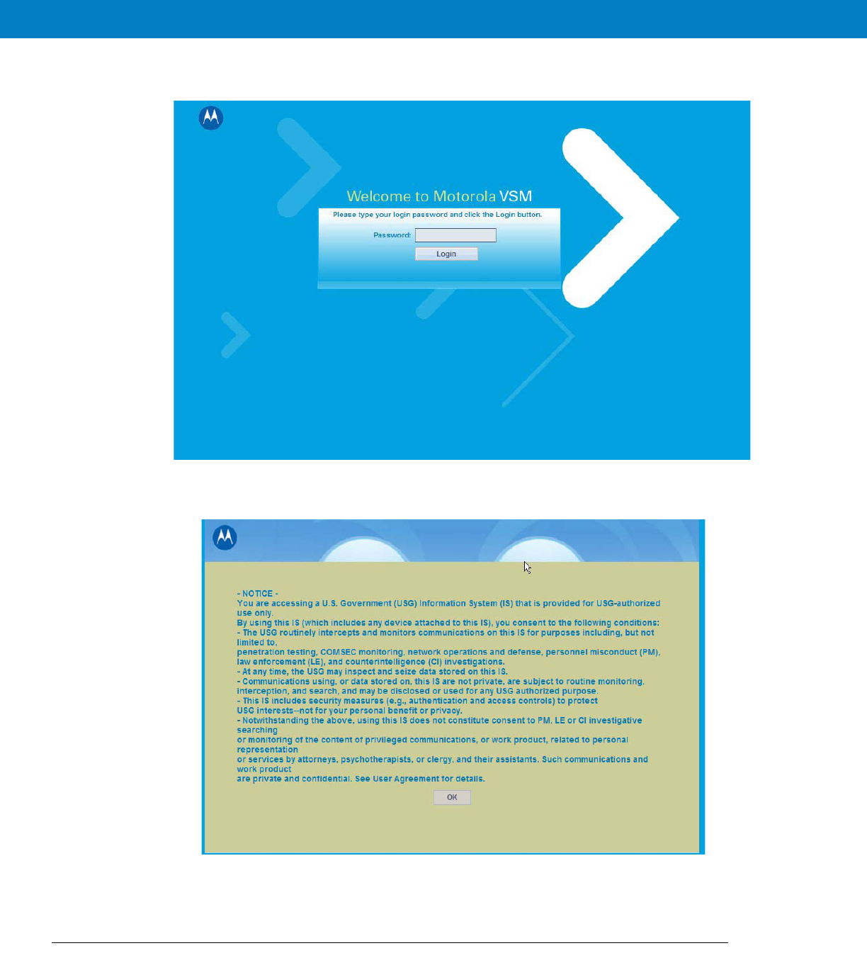
5. The following login window appears.
The default password is “motorola”.
6. Enter the password and click the “Login”. The following login banner appears after successful login.
This is a default banner. Your service provider may provision your VML700 with a different one.
7. Click the “OK” button to enter the configuration wizard.
The Configuration Wizard
After login, the configuration wizard starts.
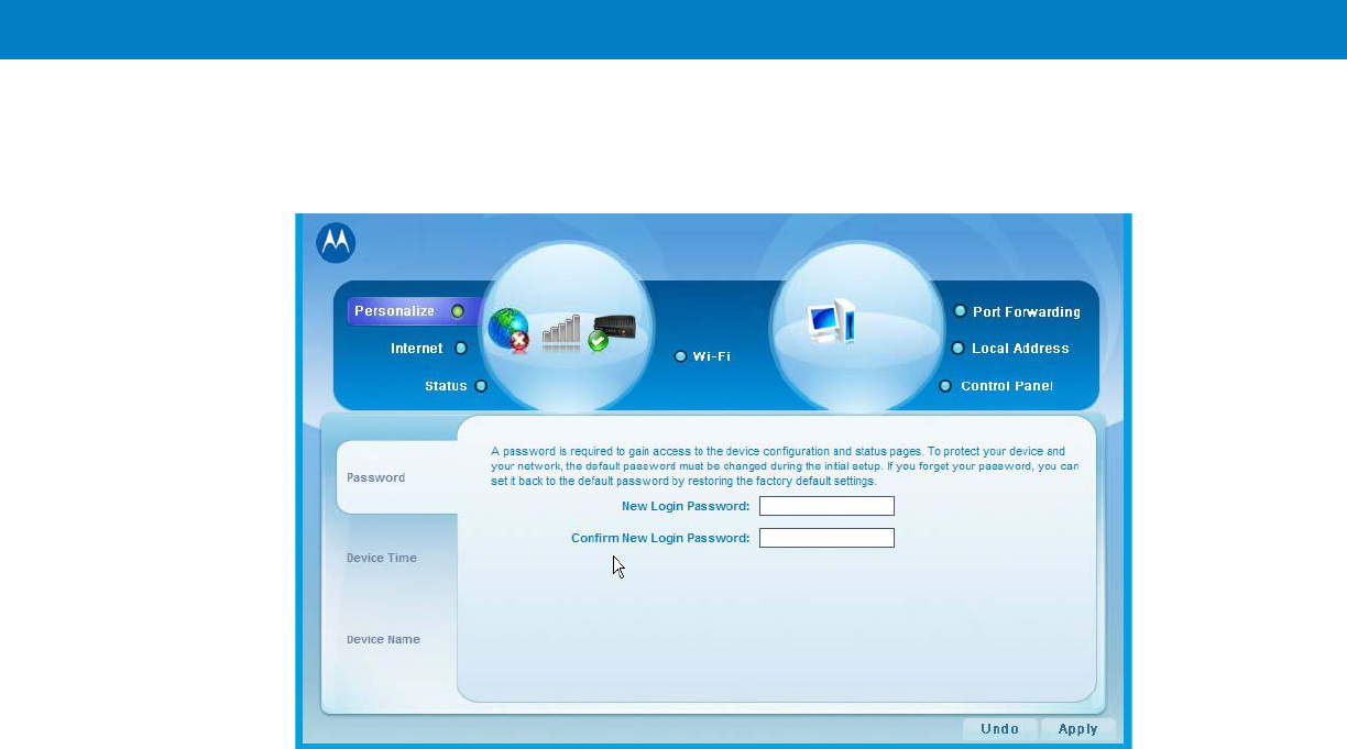
Configuring and Monitoring the VML700 3 - 3
Changing the Login Password
1. To change your login password, enter “New Login Password” and “Confirm New Login Password”.
2. Click “Apply” for the new password to take affect.
Configuring the LTE VML700 Time Zone
1. The following window appears.
2. Using the pull-down menu, select the required Time Zone.
3. If required, check the “Auto Adjust for Daylight Saving Time” checkbox.

4. When finished, click “Next” to continue to LTE security configuration.
Configuring the VML700 Security
If required by your service provider, you will need to configure your VML700 security settings.
1. The following window appears.
2. Using the pull-down menu, select the required authentication method.
Two Authentication Methods are available (check with your service supplier): EAP-TLS does not require user
name and password, and EAP-TTLS/MS-CHAPv2 that require user name and password.
3. If EAP-TTLS/MS-CHAPv2 Authentication Method is selected, the User Name, Password and Password
Confirmation fields are enabled.
4. Fill in the required user name and password.
5. When finished, click “Apply”.
Configuring the Ignition Switch
1. Turn the VML700 On by pressing the On/Off button on the LED Indicator Panel to On.

2. Click the “Control Panel” menu item and select the “System” tab. The following window appears.
3. To enable Ignition Sense, check the “Enable Ignition Sense” checkbox.
4. Click the “Apply” button.
Configuring WiFi
1. Click the “WiFi” menu item and select the “General” tab. The following window appears.
2. To enable the WiFi service, check the “Enable Wi-Fi Service” checkbox.

3. Select the Wi-Fi Mode using the drop-down menu.
4. Select the operating mode. The available operating modes are: 802.11b, 108.11g and 108.11b/g.
5. Click the “Apply” button. The following window appears.
6. Enter the Wi-Fi network name (SSID). The default value is “motorola”.
7.
8. Select the operating channel. The available values are 1 - 6, or Auto.
9. Click the “Apply” button.
Monitoring the VML700 Operation
Verify that the Status Utility is installed on your computer.
When your VML700 is up and running, a signal strength icon is displayed on the status tray.
This icon displays the following general information:
•
Received signal strength (bars).
•
Type of connection, indicated by a letter (LTE, EVDO, WiFi).
•
A set of 3 colored indicators that are explained in the example below.
The icons also enables the access into the status utility screens.
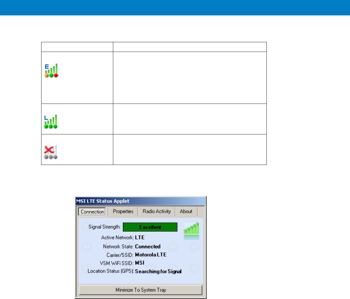
1. The following is an example of the icons displayed.
2. To access the status utility, double click the tray icon.
3. The following “Connection” screen is displayed as a default.
Icon Description
•
E - EVDO active.
•
Signal strength bars - the more green bars, the better is
the reception.
•
Bottom LEDs - in this example, Orange LED-LTE
inactive, Green LED-EVDO connected, Red LED-WiFi is
in fault state.
L - LTE active, all bottom LEDs are green, full reception.
No connection between the VML700 and the PC.

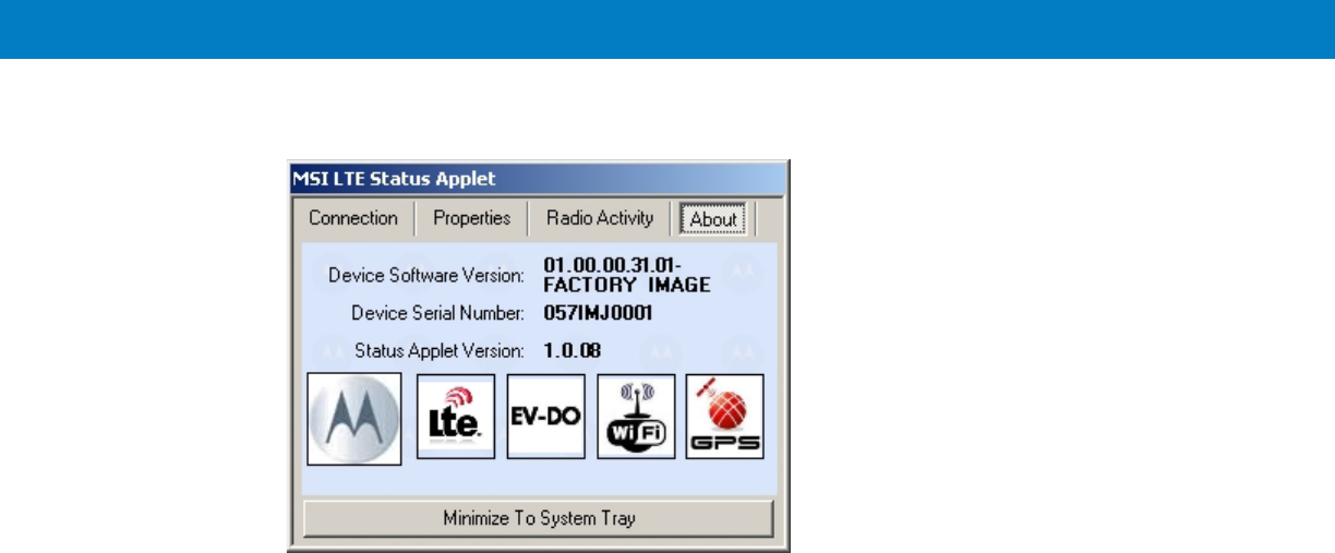
4. Click the upper tabs to receive the required system information you need.
5. If you are configured as a WiFi Client, the following message appears about 50 seconds before your client
status is terminated.
6. To minimize the status utility, click the “Minimize To System Tray” button on bottom of the screen.


Chapter 4 Troubleshooting
Introduction
Motorola has made every effort to ensure that this product is of excellent quality. However, if you experience any
problems with the product, please contact your local Motorola representative with product related information.
For complete information on ordering required parts and kits, contact your local customer service representative
and refer to Appendix B, Reference.
Troubleshooting
This paragraph, gives details regarding possible malfunctions that may occur after first time installation of the
VML700, their probable cause and the recommended corrective action.
Malfunction Probable Cause Corrective Action
VML700 does not turn On.
1. Power cable is not properly connected.
1. Check the cable connections,
connect as required and turn the
VML700 On.
2. Verify that the Power LED is solid red
(standby mode).
2. On/Off push button was not properly
pressed.
1. Apply power to the modem.
2. Press the On/Off push button for at
least 2 sec.
3. Verify that the Power LED is blinking
orange in "ignition enabled" mode, or
blinking green and then solid green in
"ignition disabled" mode.
No LAN/Ethernet connection. LAN/Ethernet cable is not connected. Connect the LAN/Ethernet cable (refer
to How to Install the LAN/Ethernet
Cable on page 2-12) and verify that the
LAN LED is green.

No GPS reception. GPS cable (from Main antenna) is not
connected.
1. Connect the GPS cable (refer to
How to Install the Main Antenna Cables
on page 2-12).
2. Verify that the GPS LED is blinking
orange and then changed to solid
green.
No WiFi connection. Div/WiFi cable (from Diversity antenna)
is not connected.
1. Connect the Div/WiFi cable (refer to
How to Install the Diversity Antenna
Cable on page 2-12).
2. Verify that the WiFi LED is
blinking/solid green.
No EVDO connection. EVDO cable (from Main antenna) is not
connected.
1. Connect the EVDO cable (refer to
How to Install the Main Antenna Cables
on page 2-12).
2. Turn the VML700 On.
3. Verify that the EVDO LED is
blinking orange/green and then change
to solid green.
No LTE connection. 1. SIM is not inserted/damaged. 1. Insert a new SIM.
2. Close the SIM door.
3. Turn the VML700 On.
4. Verify the LTE LED is blinking
orange/green and then change to solid
green.
2. LTE cable (from Main antenna) is not
connected.
1. Connect the LTE cable (refer to
How to Install the Main Antenna Cables
on page 2-12).
2. Verify the LTE LED is blinking
orange/green and then change to solid
green.

Chapter 5 Using the VML700
General
The VML700 modem installed in your vehicle is a plug and play modem and requires no user intervention. The
VML700 should be turned on automatically upon your vehicle ignition and operate properly.
If you detect any malfunction in the VML700 operation, refer to Troubleshooting on page 4-1.


Appendix A Specifications
Physical
Communication Ports
RF Ports
Power Ports
Dimensions (Modem) 8.07”x7.87”x1.71” (20.5cm x 20cm x 4.35mm + 1mm)
Weight (Modem) 6 Pounds (2.5 Kg)
Amphenol LAN – Ethernet 10/100 – RJ45
USB 2.0 high speed– Micro AB (HW ready)
LTE Main Rx/Tx SMA connector
Diversity – LTE secondary Rx/ EVDO
secondary Rx/WiFi
Reverse SMA connector
EVDO Main Rx/Tx TNC connector
GPS SMC connector
Power 9-pin D-TYPE

LEDs
Operating Temperature
Power
LED Name Power LAN LTE EVDO WiFi GPS
LED Status
OFF Power off No link Off Off Off Off
Solid Green Power on Link is on Connected Connected Available Tracking
Blinking
Green
Powering up TX/RX
Activity
Connecting/
Registering
Connecting/
Registering
TX/RX Activity --
Solid Orange No Ignition
The user
turns the
power On
(power
button
pressed) but
ignition is off.
-- -- -- -- --
Blinking
Orange
-- -- Searching for
signal
Searching for
signal
-- Searching for
signal
Solid Red -- -- Problem/
Overheat
Problem/
Overheat
Problem/
Overheat
Problem
Blinking Red Standby
External
power is
connected to
the system.
-- -- -- -- --
Rapid
Blinking Red
Problem SIM door is
open
Ambient temperature -30°C to +60°C
Input Voltage 11 to 16.60 VDC
RF Power Modes
LTE
EVDO
WiFi
Pout = 23.5 dBm
Pout = 23.5 dBm
Pout = 12.5 dBm
Power Consumption Amplifiers are Class AB.
Modem Standby < 0.3 A RMS
Modem Transmit < 1 A RMS

Specifications A - 3
Main Antenna
LTE
EVDO
GPS
Diversity Antenna
Type Sleeve Dipole
Frequency 746 - 798 MHz
Physical Texin 285 and Geloy XP4025 UV
Impedance 50 Ohms (nominal)
Polarization Vertical Linear
Height 17 inches (43cm)
Azimuth pattern Omni-directional
Elevation beamwidth 60 deg
Type Folded monopole
Frequency 821 - 896MHz, 1850 - 1990MHz
Physical PCB
Impedance 50 Ohm
Polarization Linear vertical
Height 65mm
Azimuth pattern Omni-directional
Elevation beamwidth 800MHz band - 60deg, 1900MHz band 40deg.
Type Active patch antenna
Frequency 1575.42 MHz
Impedance 50 Ohms (nominal)
Polarization Circular RHCP
System Gain (including cable) 11 dB
Type Wideband folded Monopole
Frequency 746 - 2500 MHz
Physical Fiberglass UV protected
Impedance 50 Ohms (nominal)
Polarization Vertical Linear
Height 1.77 inches (4.5Cm)

RF Characteristics
Azimuth pattern Omni-directional
Elevation beamwidth 35 deg
Frequency
LTE
EVDO BC0
EVDO BC1
WiFi
746-756 MHz, 777-787 MHz
758-768 MHz, 788-798 MHz
824-849 MHz, 869-894 MHz
1850-1910 MHz, 1930-1990 MHz
2401-2472 MHz
Bandwidth
LTE 5 MHz
10 MHz
EVDO 1.3 MHz
WiFi 20 MHz (802.11b/g)
Output transmit power
LTE 23.5 dBm
EVDO 23.5 dBm
WiFi 12.5 dBm
Receiver sensitivity
LTE 10 MHz -94dBm
5 MHz -97 dBm
EVDO -105.5 dBm
WiFi (802.11g) -87 dBm
Frequency Stability
LTE +/- 2.5 ppm
EVDO BC0 +/- 300 Hz
BC1 +/- 150 Hz
WiFi +/- 20 ppm

Appendix B Reference
Replacement Parts
Replace damaged parts with identical replacement parts.
For complete information on ordering required parts and kits, contact your local customer service representative.
Replacement Parts List
Kit/Part Number Description
Antennas
FAF5266A Main Antenna
FTN7651A Diversity Antenna
Bracket, Screws & Washers
0312002B14 Mounting Screw, Bracket to Car, 8
03013013001 Mounting Screw, VSM to Bracket, 8
0487779V56 Flat Washer, VSM to Bracket, 8
0487623U12 Spring Washer, VSM to Bracket, 8
07013065001 Bracket, 2
Cables
3071815Y61 LAN/Ethernet Cable (177”/450 cm)
30013060001 DC Power & Ignition Cable (177”/450 cm)

B - 2 VM L700 Installation Guide
Kit Replacement Parts List
Kit/Part Number Description
F4080A VML700, LTE VSM Modem

6802987C90-A June 2011
MOTOROLA and the Stylized M Logo and Symbol and the Symbol logo are registered in the U.S. Patent and Trademark Office.
All other product or service names are the property of their respective owners.
© Motorola, Inc. 2010
@6802987C01@
Ex8 Users Manual
VML700 - LTE Vehicular Subscriber
Modem (VSM)
Installation Guide

VML700 - LTE VSM
Installation Guide
6802987C90
Revision A
June 2011

ii VML700 Installation Guide
© 2011 by Motorola Solutions, Inc. All rights reserved.
No part of this publication may be reproduced or used in any form, or by any electrical or mechanical means,
without permission in writing from Motorola. This includes electronic or mechanical means, such as
photocopying, recording, or information storage and retrieval systems. The material in this manual is subject to
change without notice.
The software is provided strictly on an “as is” basis. All software, including firmware, furnished to the user is on
a licensed basis. Motorola grants to the user a non-transferable and non-exclusive license to use each
software or firmware program delivered hereunder (licensed program). Except as noted below, such license
may not be assigned, sublicensed, or otherwise transferred by the user without prior written consent of
Motorola. No right to copy a licensed program in whole or in part is granted, except as permitted under
copyright law. The user shall not modify, merge, or incorporate any form or portion of a licensed program with
other program material, create a derivative work from a licensed program, or use a licensed program in a
network without written permission from Motorola. The user agrees to maintain Motorola’s copyright notice on
the licensed programs delivered hereunder, and to include the same on any authorized copies it makes, in
whole or in part. The user agrees not to decompile, disassemble, decode, or reverse engineer any licensed
program delivered to the user or any portion thereof.
Motorola reserves the right to make changes to any software or product to improve reliability, function, or
design.
Motorola does not assume any product liability arising out of, or in connection with, the application or use of
any product, circuit, or application described herein.
No license is granted, either expressly or by implication, estoppel, or otherwise under any Motorola, Inc.,
intellectual property rights. An implied license only exists for equipment, circuits, and subsystems contained in
Motorola products.
MOTOROLA SOLUTIONS and the Stylized M Logo and Symbol and the Symbol logo are registered in the US
Patent & Trademark Office. Bluetooth is a registered trademark of Bluetooth SIG. Microsoft, Windows and
ActiveSync are either registered trademarks or trademarks of Microsoft Corporation. All other product or
service names are the property of their respective owners.
Patents
This product is covered by one or more of the patents listed on the website:
http://www.motorola.com/enterprisemobility/patents.
Warranty
For the complete Motorola hardware product warranty statement, go to:
http://www.motorola.com/enterprisemobility/warranty.
Legal Notice
The VML700 OSS legal notice may be found in the root directory of the LTE VSM Software CD (P/N
82013113001).

Revision History
Changes to the original manual are listed below:
Change Date Description
A Initial release

iv VML700 Installation Guide

Table of Contents v
Patents........................................................................................................................... ii
Warranty ........................................................................................................................ ii
Legal Notice ................................................................................................................... ii
Revision History ............................................................................................................. iii
About This Guide
Introduction .................................................................................................................... vii
Configurations ................................................................................................................ vii
Chapter Descriptions ..................................................................................................... viii
Notational Conventions.................................................................................................. ix
Related Documents ....................................................................................................... ix
Service Information ........................................................................................................ ix
Safety............................................................................................................................. x
FCC Interference ........................................................................................................... x
Chapter 1: VML700 Description
The VML700 Unit .......................................................................................................... 1-1
Modem .......................................................................................................................... 1-2
Connectors Panel ......................................................................................................... 1-2
LED Indicator Panel with On/Off Button and SIM Card Door ........................................ 1-4
LED Indicators Functions .............................................................................................. 1-5
Control .......................................................................................................................... 1-5
SIM Card........................................................................................................................ 5
Chapter 2: Installation
Unpacking and Inspecting the Shipment ...................................................................... 2-1
Safety and General Information .................................................................................... 2-1
Planning the Installation ................................................................................................ 2-3
Installation Constraints ............................................................................................ 2-3
Cables Routing ........................................................................................................ 2-4
Drilling Holes ........................................................................................................... 2-4
Tools and Equipment .............................................................................................. 2-5
Antennas ....................................................................................................................... 2-6
Main Antenna .......................................................................................................... 2-6
Diversity Antenna .................................................................................................... 2-7
Cables ........................................................................................................................... 2-7
Mounting Brackets ........................................................................................................ 2-8
Modem Installation Process .......................................................................................... 2-8
Antennas Mounting ....................................................................................................... 2-9
Special Antennas Installation Considerations ......................................................... 2-9
Modem Installation Procedure ...................................................................................... 2-10
Cables Routing and Connection Procedure .................................................................. 2-10
DC Power and Ignition Cable Installation ................................................................ 2-10
Main Antenna Cables Installation ............................................................................ 2-12
Diversity Antenna Cable Installation ....................................................................... 2-12
LAN/Ethernet Cable Installation .............................................................................. 2-12
Cap Installation ............................................................................................................. 2-12

Table of Contents vi
Chapter 3: Configuring and Monitoring the VML700
Introduction ................................................................................................................... 3-1
Prior to Configuration .................................................................................................... 3-1
The Configuration Wizard ............................................................................................. 3-2
Changing the Login Password ................................................................................ 3-3
Configuring the LTE VML700 Time Zone ................................................................ 3-3
Configuring the VML700 Security ........................................................................... 3-4
Configuring the Ignition Switch ..................................................................................... 3-4
Configuring WiFi ........................................................................................................... 3-5
Monitoring the VML700 Operation ................................................................................ 3-6
Chapter 4: Troubleshooting
Introduction ................................................................................................................... 4-1
Troubleshooting ............................................................................................................ 4-1
Chapter 5: Using the VML700
General ......................................................................................................................... 5-1
Appendix A: Specifications
Physical ......................................................................................................................... A-1
Communication Ports .............................................................................................. A-1
RF Ports .................................................................................................................. A-1
Power Ports ............................................................................................................. A-1
LEDs ....................................................................................................................... A-2
Operating Temperature ........................................................................................... A-2
Power ...................................................................................................................... A-2
Main Antenna .......................................................................................................... A-3
Diversity Antenna .................................................................................................... A-3
Communication Channel Packet Error Rate ........................................................... A-4
RF Characteristics ................................................................................................... A-4
Appendix B: Reference
Replacement Parts ....................................................................................................... B-1
Replacement Parts List ........................................................................................... B-1
Kit Replacement Parts List ...................................................................................... B-2

About This Guide
Introduction
The VML700 LTE VSM Installation Guide provides general instructions for installing, setting up, operating, and
troubleshooting the VML700.
NOTE The names LTE VSM and VML700 are interchangeable and they are both used in this manual.
Configurations
This guide includes the following configuration:
•
F4080A model VML700

Chapter Descriptions
Topics covered in this guide are as follows:
•
Chapter 1, VML700 Description provides the product overview.
•
Chapter 2, Installation provides unpacking instructions and all required procedures for installing the VML700.
•
Chapter 3, Configuring and Monitoring the VML700 provides the procedures that enable configuring the
VML700 for best operation.
•
Chapter 4, Troubleshooting provides details regarding possible malfunctions that may occur after first time
installation of the VML700, their probable cause and the recommended corrective actions.
•
Chapter 5, Using the VML700 provides general information regarding the use of the VML700.
About This Guide vi
The following conventions are used in this document:
•
Italics are used to highlight the following:
•Chapters and sections in this and related documents
•Dialog box, window and screen names
•Drop-down list and list box names
•Check box and radio button names
•
Bold text is used to highlight the following:
•Key names on a keypad
•Button names on a screen.
•
bullets (•) indicate:
•Action items
•Lists of alternatives
•Lists of required steps that are not necessarily sequential
•
Sequential lists (e.g., those that describe step-by-step procedures) appear as numbered lists.
Related Documents
•
VML700 LTE VSM Basic Service Manual, p/n 6802988C02
Service Information
If you have a problem with your equipment, contact Motorola Enterprise Mobility support for your region. Contact
information is available at: http://www.motorola.com/enterprisemobility/contactsupport.
When contacting Enterprise Mobility support, please have the following information available:
•
Serial number of the unit
•
Model number or product name
•
Software type and version number
Motorola responds to calls by e-mail, telephone or fax within the time limits set forth in service agreements.
If your problem cannot be solved by Motorola Enterprise Mobility Support, you may need to return your equipment
for servicing and will be given specific directions. Motorola is not responsible for any damages incurred during
shipment if the approved shipping container is not used. Shipping the units improperly can possibly void the
warranty.
If you purchased your Enterprise Mobility business product from a Motorola business partner, please contact that
business partner for support.

Safety
Before installing/using this product, the installer/operator must be familiar with the RF energy awareness
information and operating instructions in the “Product Safety and RF Energy Exposure Booklet” enclosed with the
VML700 LTE VSM (Motorola Publication part number 6881095C99) to ensure compliance with Radio Frequency
(RF) energy exposure limits.
FCC Interference
This device complies with Part 15 of the FCC Rules. Operation is subject to the following two conditions:
(1) This device may not cause harmful interference.
(2) This device must accept any interference received, including interference that may cause undesired operation.
This Class A/B digital apparatus complies with Canada ICES-003.
Changes or modifications made to this product, not expressly approved by Motorola, will void the user's authority to
operate the equipment, per FCC Rule Part 15.21.

1 - 2 VML700 Installation Guide
Figure 1-1
VML700 - General View
For detailed specifications of the VML700 unit, see Appendix A: Specifications.
Modem
The modem has a Connectors panel (back panel) and a LED Indicator panel with On/Off button (front panel).
Connectors Panel
The VML700 Connectors panel consist of the following (see Figure 1-2):
•
LTE Main Rx/Tx – SMA type connector
•
Diversity – LTE secondary Rx/EVDO secondary Rx/WiFi – reverse SMA type connector
•
EVDO Main Rx/Tx – TNC type connector
•
GPS – SMC type connector
•
LAN – Ethernet 10/100 – RJ45 type connector
1Modem
2LED Indicator Panel (Front Panel)
3Connectors Panel (Back Panel - not shown)
1
2
3

VML700 Description 1 - 3
•
USB 2.0 high speed– Micro AB type connector (HW ready)
•
Power – 9-pin DTYPE connector
Figure 1-2
Connectors Panel
2
1
56
1RF SMA female type connector (LTE)
RF SMA reversed female type connector (DIV/WiFi)
RF TNC female type connector (EVDO)
4RF SMC female type connector (GPS)
5LAN/Ethernet communication connector (RJ45)
6Micro AB type connector (USB 2.0)
7DC power connector
34
7

1 - 5
LED Indicators Functions
Table 1-1 describes the functions of the LED indicators on the VML700 front panel.
Control
The On/Off button is used to turn the VML700 On or Off.
SIM Card
A SIM is required for the operation of the modem.
Table 1-1
LED Indicators Functions
LED Name Power LAN LTE EVDO WiFi GPS
LED Status
OFF Power off No link Off Off Off Off
Solid Green Power on Link is on Connected Connected Available Tracking
Blinking Green Powering up TX/RX
Activity
Connecting/
Registering
Connecting/
Registering
TX/RX Activity --
Solid Orange No Ignition
The user
turns the
power On
(power
button
pressed) but
ignition is off.
-- -- -- -- --
Blinking
Orange
-- -- Searching for
signal
Searching for
signal
-- Searching for
signal
Solid Red -- -- Problem/
Overheat
Problem/
Overheat
Problem/
Overheat
Problem
Blinking Red Standby
External
power is
connected to
the system.
-- -- -- -- --
Rapid Blinking
Red
Problem SIM door is
open

1 - 6 VML700 Installation Guide

Chapter 2 Installation
Unpacking and Inspecting the Shipment
Unpack your shipment and check the contents to ensure that you have received all the specified items.
Thoroughly inspect the equipment for shipping damage as soon as possible after delivery. Report any damage you
find to your Motorola Customer Service representative immediately.
Safety and General Information
A properly installed VML700 unit minimizes service calls. When mounting the VML700 unit components, consider
the following factors:
•
The mounting surface must have sufficient strength to support the equipment being mounted and to prevent
it from becoming loose over time.
•
Do not attach components to any part of the vehicle subjected to excessive vibration.
•
Do not mount the VML700 unit on a flat surface where the unit could become partially submersed in water.
•
The proposed location of the equipment being mounted or wires/cables attached must not interfere with
driver/passenger seating or leg space.
•
Select a location such that heat from the unit does not damage any wiring or any other plastic or
heat-sensitive parts of the automobile.
•
Use the supplied mounting hardware.
•
Leave sufficient space around the VML700 unit for air flow and installation.
•
Select a location that permits routing the cables as directly as possible.
•
Ensure that the cables are not stretched, and not subject to heat from the engine, transmission housing or
heating ducts.
•
Crimp connectors securely.
•
Do not run cables over sharp edges that may cause excessive wear or chaffing of the cable insulation.
•
Do not install components in locations where they may cause interference to the operation of the vehicle's
controls.
•
Only qualified personnel may install communication equipment.
•
Ensure secure tightening of cable connectors.
Install this product in a vehicle in accordance with the vehicle manufacturer’s guidelines and the instructions detailed in
this manual. Use only the Motorola parts specified in this manual.
Check the required mounting locations. It might be necessary to penetrate the bulkhead to reach the battery.
Before drilling commences, ensure cable clearance on the opposite side of the bulkhead and do not install the
vehicle’s Electronic Control Modules (ECM’s) on the opposite side of the bulkhead. Protect the cable where it
passes through the bulkhead by using a grommet or similar protective measures.
If necessary, contact the vehicle manufacturer for air bag information specific to the vehicle.
CAUTION Installing the VML700 at the end of the vehicle above the exhaust pipe may cause the VML700 to
overheat.
WARNING!VEHICLES EQUIPPED WITH AIR BAGS
An air bag inflates with great force. DO NOT place objects, including communications
equipment, in the area over the air bag or in the air bag deployment area. If the communication
equipment is improperly installed and the air bag inflates, this could cause serious injury.
WARNING!Verify that none of the vehicle’s systems are affected by use of the unit, e.g. cruise control,
ABS breaking, traction control, engine management, direction indicators, lights, etc.
WARNING!Use existing openings through the bulkhead to avoid drilling. If drilling is a must, verify not to
damage the Vehicle Electronic Control Modules (ECM’s), fuel pipes, brake pipes, and/or cable
looms.
WARNING!For vehicles equipped with electronic braking systems, see “ANTI-SKID BRAKING
PRECAUTIONS”, Motorola publication 68P81109E34.
It is mandatory that modems installed in vehicles fuelled by liquefied petroleum gas conform
to the National Fire Protection Association standard NFPA 58, which applies to vehicles with
a liquid propane (LP) gas container in the trunk or other sealed off space within the interior of
the vehicle. The NFPA 58 requires the following:
(1) The space in which the LP gas container and its fittings are located must be isolated by a
seal from the space containing modem equipment.
(2) Removable (outside) filling connections shall be used.
(3) The container space shall be vented to the outside.
Planning is the key to fast, easy and safe installation.
Installation Constraints
Refer to the Safety Instructions in “Product Safety and RF Energy Exposure Booklet for Mobile Two-Way Radios in
Vehicles or as Fixed Site Control” P/N 6881095C99.
The LTE VML700 must be installed in the car’s trunk, on the floor or the side walls (cooling fins facing up, or to the
side).
Figure 2-1 shows a typical VML700 installation in a car.
VML700 - Typical Car Installation
Before beginning the installation process make sure that the space available at the installation site is adequate for
the modem and its accessories. Each installation configuration requires a different area for mounting the modem
without obstruction.
When choosing a location, ensure easy installation and replacement of the unit.
MPORTANT Take the following points into consideration when selecting a location and planning the installation.
IMPORTANT The VML700 must not be installed with the cooling fins facing down. Failure to comply may cause
overheat problems and performance degradation.
Diversity
MAIN
VML700
Trunk Floor
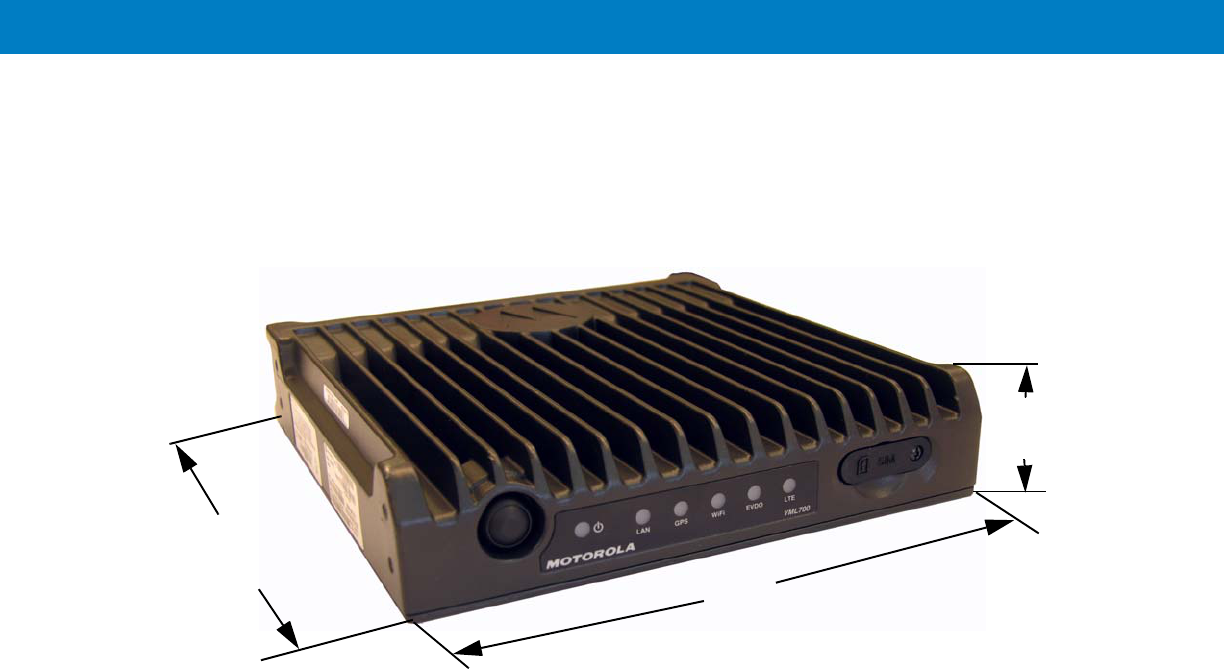
Figure 2-2 gives the VML700 dimensions.
VML700 - Dimensions
Cables Routing
•
Before running a wire or drilling a hole, inspect the vehicle and determine how and where you intend to
mount the antenna, modem, and the input/output device.
•
Plan wire and cable routing to provide maximum protection from overheating, battery acid, moving parts and
sharp edges.
•
Keep cables away from ignition circuits to reduce noise pickup in the radio equipment.
•
Verify that the cables are of sufficient length. Do not connect two short lengths with a connector; doing so
results in signal loss. Refrain from loose excess in the cables, but leave enough slack to allow reconnection if
necessary.
•
Do not run cables externally or underneath floor mats.
•
Do not locate cables where the driver or passengers can kick them or where they can interfere with operation
of the driver’s foot pedals.
•
When routing the cable, refrain from creating sharp bends or kinks.
Drilling Holes
•
Where possible, use existing holes in the bulkhead, the trunk wall and the channels above or beneath the
doors. Run cables parallel to existing car cables if appropriate.
1
1.71”
4.35cm
8.07”
20.5cm
7.87”
20cm

•
If you must drill holes, verify not to damage other wiring, break lines or gas lines.
•
When drilling a hole in the roof, take care not to snag the roof liner.
•
To prevent rusting after drilling, remove all metal burrs and residue, and completely clean the area to ensure
the removal of all steel dust.
•
Insert rubber grommets in all drilled holes to protect cables.
Tools and Equipment
•
#2 Phillips screwdriver
•
Electrical drill and drill bit set
•
X-acto knife or equivalent
•
Wire stripper
•
Long nose pliers
•
Small side cutters
•
Crimping tool
•
Wrench set, including 8 mm for tray to unit attachment
•
3 mm Allen wrench set for unit to tray attachment
•
Soldering iron and solder
•
Electrical tape

Antennas
Main Antenna
The main antenna is constructed of three antenna types (LTE, EVDO and GPS) on a single mount.
•
Kit No. FAF5266A
The antenna is provided with two short flexible coaxial cables (threads) coming out of the antenna bottom side
(LTE and EVDO). Two 12ft jumper coaxial cables are also provided in order to connect between these threads and
the modem connector. The GPS antenna is provided with 12ft coaxial cable. (see Figure 2-3).
Figure 2-3
Main Antenna


2 - 8 VML700 Installation Guide
Cables
The following cables are supplied with the VML700 (see Figure 2-5).
Figure 2-5
Cables
Mounting Brackets
Use the brackets (2 brackets are supplied) for mounting the VML700 securely on a flat surface.
Figure 2-6
Bracket Dimensions
1DC Power and Ignition cable
LAN/Ethernet cable
1
Fuse Not
Supplied
2
7.40”
(18.8cm)
2.08”
(5.3cm)
0.79”
(2cm)

2 - 9
Process 2-1 describes the steps for the modem installation.
Process 2-2 gives general instructions for mounting the antennas.
Special Antennas Installation Considerations
General Antenna Installation Safety Considerations
Main Antenna
The main antenna must be installed on the vehicle’s roof, preferably in the center of it. For best performance, a minimum
distance of 36” (91.44cm) must be kept between this antenna and any other antenna.
Diversity Antenna
It is recommended that the Diversity Antenna will be installed on the vehicle’s trunk hood. For best performance, a
minimum distance of 36” (91.44cm) must be kept between this antenna and any PSNB antenna.
Process 2-1
Modem Installation Process
1
Ensure adequate space for the installation. (See Planning the Installation on page 2-3)
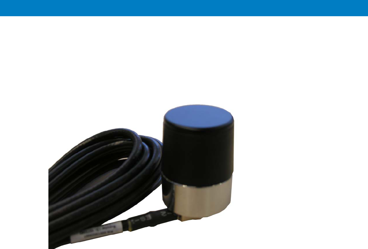
2
Install the antennas. (See Antennas Mounting on page 2-9).
3
Route the cables. (See Planning the Installation on page 2-3 and Cables Routing and Connection Procedure
on page 2-10).
4
Install the brackets and the unit. (See Modem Installation Procedure on page 2-10.).
5
Connect the DC Power and Ignition cable. (See DC Power and Ignition Cable Installation on page 2-10).
6
Connect the main antenna cables. (See Main Antenna Cables Installation on page 2-12).
7
Connect the Diversity/WiFi antenna cable. (See Diversity Antenna Cable Installation on page 2-12).
8
Connect the LAN/Ethernet cable. (See LAN/Ethernet Cable Installation on page 2-12).
9
Place caps on unused connector(s). (See Cap Installation on page 2-12).
Process 2-2
How to Mount the Antennas
1
Mount the antennas in accordance with the instructions provided with each antenna kit and with the
Product Safety and RF Energy Exposure Booklet for Mobile Two-Way Radios Installed in Vehicles or as
Fixed Site Control Stations (6881095C99) enclosed with the product.
The main and diversity antennas must be installed in a location that will ensure a distance of
at least 8” (20cm) between them and any bystander.
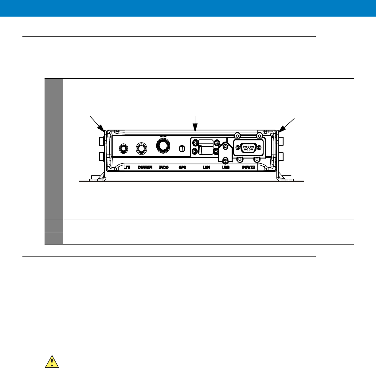
Modem Installation Procedure
Process 2-3 describes how to install the modem on a flat surface.
Cables Routing and Connection Procedure
DC Power and Ignition Cable Installation
The VML700 supports 12 V vehicle batteries, i.e. 13.8 V ±20% DC vehicle batteries.
The DC Power cable is equipped with 5-Ampere fuse (slow-blow). Verify that the vehicle electrical system can support
current values larger than that.
Connect the fuse in the red wire to the power source using the shortest practical length.
The unit is used with a negative ground system only.
Process 2-3
How to Install the Modem on a Flat Surface
1
Position the two mounting brackets (1) on both sides of the modem (2) and fasten using 4 screws each. See
Figure 2-7
.
Figure 2-7
Mounting Brackets
2
Locate the VML700 with the mounting brackets attached on the dedicated flat surface.
3
Centerpunch the marked spots and fix the modem in position using the self-drilling supplied screws.
1
12
Insert the fuse after making and carefully inspect all connections.
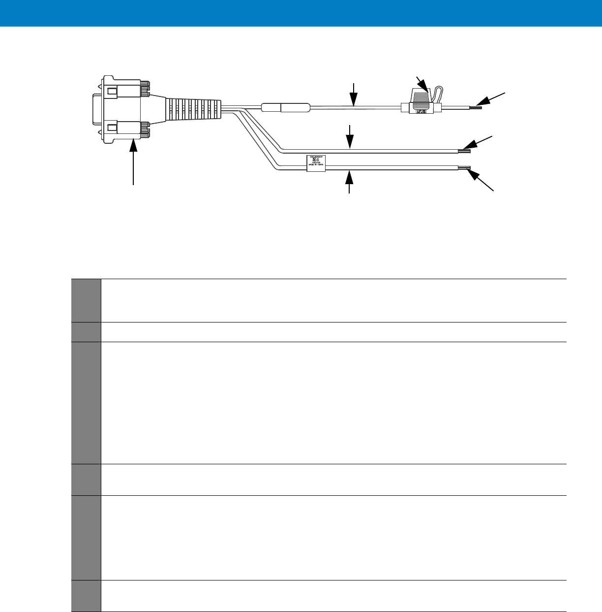
See Figure 2-8 before routing or connecting the DC Power and Ignition cable and use the following process.
Figure 2-8
DC Power and Ignition Cable Routing Into Engine Compartment
Process 2-4 describes how to install the DC power and ignition cable.
Process 2-4
How to Install the DC Power and Ignition Cable
1
Route the DC Power cable’s leads through the bulkhead and into the engine compartment. Use an existing
opening or, if necessary, drill a 2 cm (26/32 inch) diameter hole through the bulkhead. Insert a grommet into
the hole to prevent damage to the DC Power cable.
2
Cut the black lead to the desired length and connect it to the negative (-) battery terminal.
3
On the engine side of the bulkhead, connect the red (A+) lead to the vehicle’s battery as follows:
a. Cut the long red lead to the desired length. Verify that the fuse holder is at a distance of 20-30 cm away
from the connection point, ensuring that it is not close to any hot engine component.
b. Mount the fuse holder using the provided mount, and dress wires as necessary. Connect the red lead
plug adaptor (on the fuse holder) to the matching receptacle on the red lead of the DC Power cable.
c. Remove the fuse from the fuse holder and connect the red lead of the DC Power cable to the positive (+)
battery terminal. Cable tie the wire every 4” (10 cm) along its length, do not tie to existing vehicle
systems.
d. Insert the fuse into the fuse holder.
5
Verify that the cables in the engine compartment do not obstruct any of the vehicle controls or touch hot or
moveable parts of the engine.
6
For ignition installation, perform the following steps:
a. Cut the green lead to the desired length.
b. Connect the green lead of the DC Power cable to ignition (+). Cable tie the wire every 4” (10 cm) along
its length, do not tie to existing vehicle systems.
c. Verify that the voltage is high with ignition on, during cranking and while vehicle is running. When ignition
is off, the voltage is low.
7
Connect the DC Power and ignition cable connector to POWER connector on the VML700 Connectors panel.
Fasten the connector using the four fastening screws.
Power & Ignition Connector to
Modem Green Lead
Red Lead
Black Lead
To Battery (+)
To Battery (-)
To Ignition (+)
Fuse

Main Antenna Cables Installation
Diversity Antenna Cable Installation
LAN/Ethernet Cable Installation
Cap Installation
Process 2-5
How to Install the Main Antenna Cables
1
The antenna is provided with two short flexible coaxial cables (threads) coming out of the antenna
bottom side (LTE and EVDO). Two 12ft jumper coaxial cables are also provided in order to connect
between these threads and the modem connector. The GPS antenna is provided with 12ft coaxial
cable. Do not trim these cables after routing them. Form a service loop to any cable excess length.
The service loop should have a minimum bend radius of 1” (2.54cm). Use plastic cable ties to secure
the cable.
2
Connect the RF cables from the antenna to LTE, EVDO and GPS connectors on the Connectors panel (the
order of connection is not important). Do not use pliers or any other metallic tool for tightening. Hand tighten
only! Fully tighten the antenna cable connector and verify it is well fastened.
Process 2-6
How to Install the Diversity Antenna Cable
1
Connect the RF cable from the antenna to DIV/WiFi connector on the Connectors panel. Do not use pliers or
any other metallic tool for tightening. Hand tighten only! Fully tighten the antenna cable connector and verify
it is well fastened.
Process 2-7
How to Install the LAN/Ethernet Cable
1
Connect the LAN/Ethernet cable from the LAN connector on the Connectors panel to the input/output device.
Do not use pliers or any other metallic tool for tightening. Hand tighten only!
2
Secure the LAN/Ethernet cable to the vehicle body at a distance of 7.8 + 1.9” (20 + 5cm) from the VML700.
Process 2-8
How to Install Cap(s) on Unused Connector(s)
1
Screw cap(s) on unused port(s) to protect connector(s).

Chapter 3 Configuring and Monitoring the
VML700
Introduction
The VML700 is basically a plug and play modem and will, most of the time, access the network without any
configuration.
Some service providers require special security configuration. Also, there are some basic configuration that may
be done after first time installation.
This chapter provides required security configuration procedures and other general configuration procedures that
may be done by your system administrator after the modem installation completion.
In addition, this chapter describes some basic VML700 operation indications that appear on your computer and
enable you to monitor your VML700 operation.
Prior to Configuration
1. Connect a LAN/Ethernet cable between the VML700 and your computer.
2. Turn the VML700 On.
3. Verify your computer in On and open your web browser.
4. In the web address field, enter the VML700 IP address (http://192.168.15.1) and press “Enter”.

5. The following login window appears.
The default password is “motorola”.
6. Enter the password and click the “Login”. The following login banner appears after successful login.
This is a default banner. Your service provider may provision your VML700 with a different one.
7. Click the “OK” button to enter the configuration wizard.
The Configuration Wizard
After login, the configuration wizard starts.

Configuring and Monitoring the VML700 3 - 3
Changing the Login Password
1. To change your login password, enter “New Login Password” and “Confirm New Login Password”.
2. Click “Apply” for the new password to take affect.
Configuring the LTE VML700 Time Zone
1. The following window appears.
2. Using the pull-down menu, select the required Time Zone.
3. If required, check the “Auto Adjust for Daylight Saving Time” checkbox.

4. When finished, click “Next” to continue to LTE security configuration.
Configuring the VML700 Security
If required by your service provider, you will need to configure your VML700 security settings.
1. The following window appears.
2. Using the pull-down menu, select the required authentication method.
Two Authentication Methods are available (check with your service supplier): EAP-TLS does not require user
name and password, and EAP-TTLS/MS-CHAPv2 that require user name and password.
3. If EAP-TTLS/MS-CHAPv2 Authentication Method is selected, the User Name, Password and Password
Confirmation fields are enabled.
4. Fill in the required user name and password.
5. When finished, click “Apply”.
Configuring the Ignition Switch
1. Turn the VML700 On by pressing the On/Off button on the LED Indicator Panel to On.
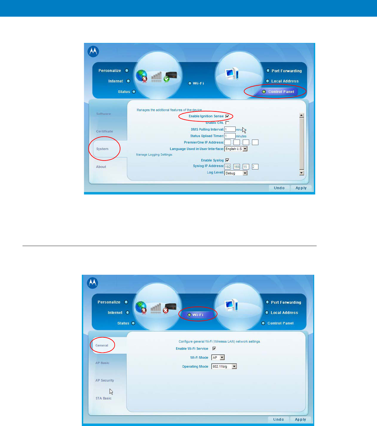
2. Click the “Control Panel” menu item and select the “System” tab. The following window appears.
3. To enable Ignition Sense, check the “Enable Ignition Sense” checkbox.
4. Click the “Apply” button.
Configuring WiFi
1. Click the “WiFi” menu item and select the “General” tab. The following window appears.
2. To enable the WiFi service, check the “Enable Wi-Fi Service” checkbox.

3. Select the Wi-Fi Mode using the drop-down menu.
4. Select the operating mode. The available operating modes are: 802.11b, 108.11g and 108.11b/g.
5. Click the “Apply” button. The following window appears.
6. Enter the Wi-Fi network name (SSID). The default value is “motorola”.
7.
8. Select the operating channel. The available values are 1 - 6, or Auto.
9. Click the “Apply” button.
Monitoring the VML700 Operation
Verify that the Status Utility is installed on your computer.
When your VML700 is up and running, a signal strength icon is displayed on the status tray.
This icon displays the following general information:
•
Received signal strength (bars).
•
Type of connection, indicated by a letter (LTE, EVDO, WiFi).
•
A set of 3 colored indicators that are explained in the example below.
The icons also enables the access into the status utility screens.

1. The following is an example of the icons displayed.
2. To access the status utility, double click the tray icon.
3. The following “Connection” screen is displayed as a default.
Icon Description
•
E - EVDO active.
•
Signal strength bars - the more green bars, the better is
the reception.
•
Bottom LEDs - in this example, Orange LED-LTE
inactive, Green LED-EVDO connected, Red LED-WiFi is
in fault state.
L - LTE active, all bottom LEDs are green, full reception.
No connection between the VML700 and the PC.
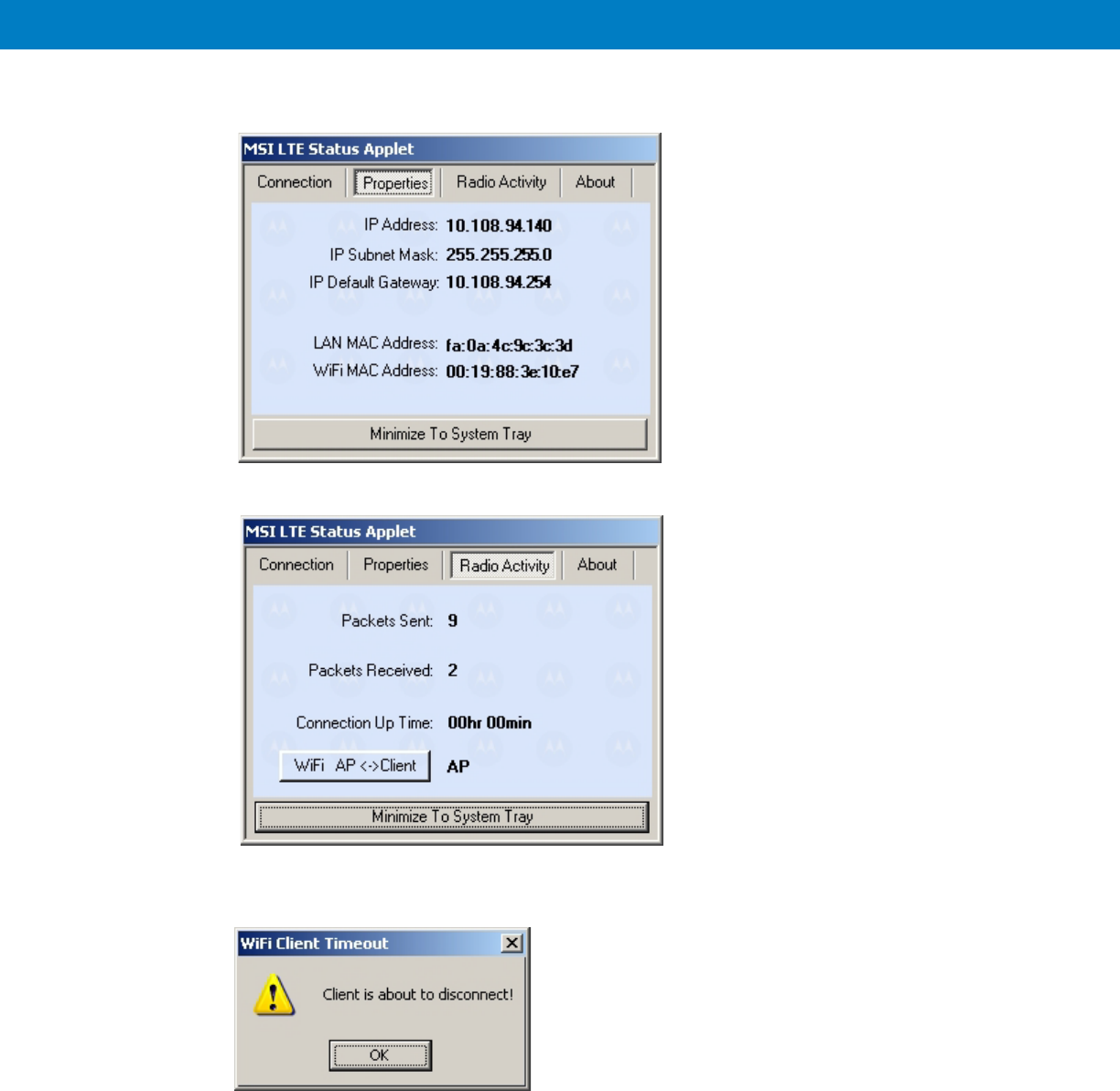
4. Click the upper tabs to receive the required system information you need.
5. If you are configured as a WiFi Client, the following message appears about 50 seconds before your client
status is terminated.

6. To minimize the status utility, click the “Minimize To System Tray” button on bottom of the screen.

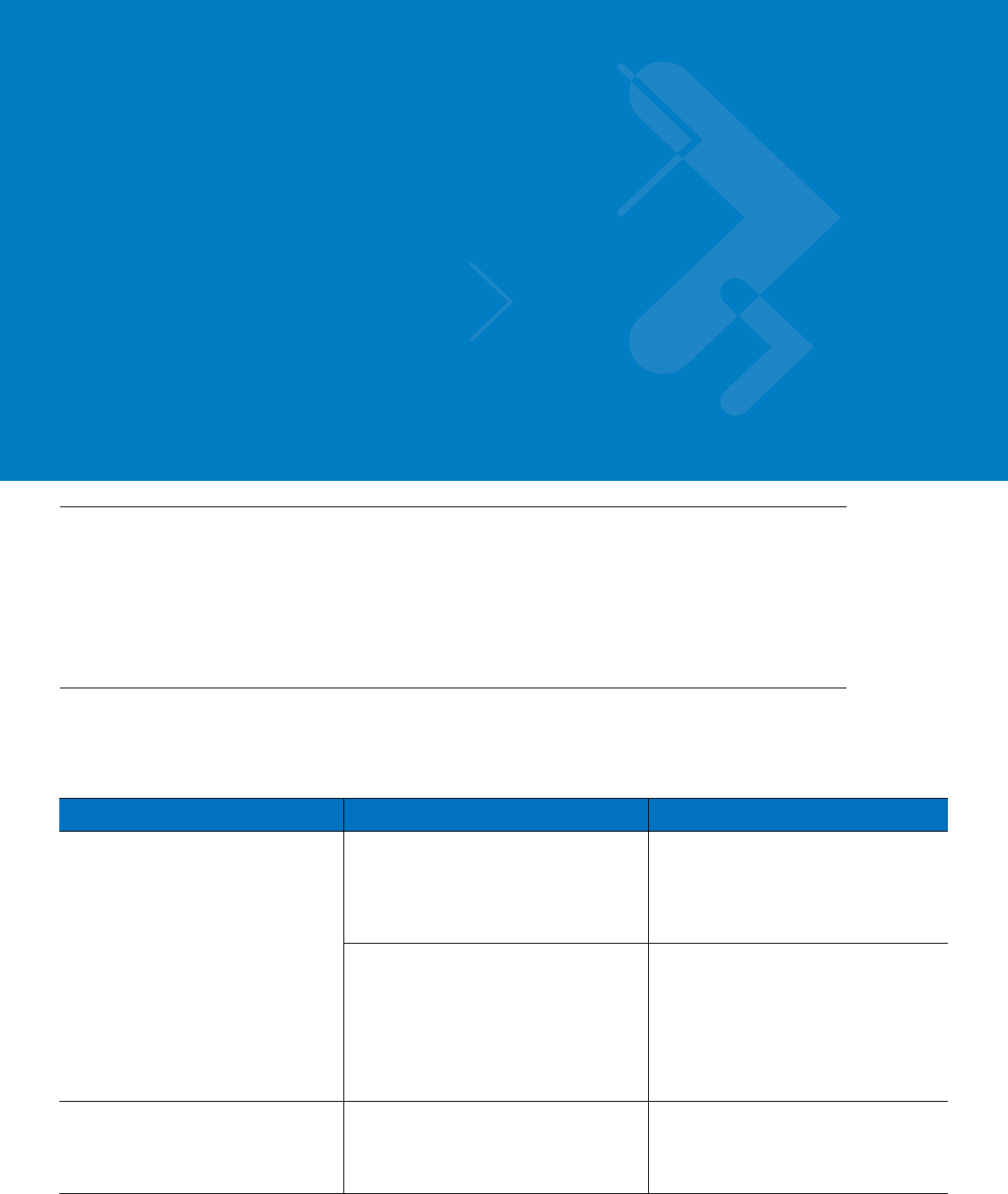
Chapter 4 Troubleshooting
Introduction
Motorola has made every effort to ensure that this product is of excellent quality. However, if you experience any
problems with the product, please contact your local Motorola representative with product related information.
For complete information on ordering required parts and kits, contact your local customer service representative
and refer to Appendix B, Reference.
Troubleshooting
This paragraph, gives details regarding possible malfunctions that may occur after first time installation of the
VML700, their probable cause and the recommended corrective action.
Malfunction Probable Cause Corrective Action
VML700 does not turn On.
1. Power cable is not properly connected.
1. Check the cable connections,
connect as required and turn the
VML700 On.
2. Verify that the Power LED is solid red
(standby mode).
2. On/Off push button was not properly
pressed.
1. Apply power to the modem.
2. Press the On/Off push button for at
least 2 sec.
3. Verify that the Power LED is blinking
orange in "ignition enabled" mode, or
blinking green and then solid green in
"ignition disabled" mode.
No LAN/Ethernet connection. LAN/Ethernet cable is not connected. Connect the LAN/Ethernet cable (refer
to How to Install the LAN/Ethernet
Cable on page 2-12) and verify that the
LAN LED is green.

No GPS reception. GPS cable (from Main antenna) is not
connected.
1. Connect the GPS cable (refer to
How to Install the Main Antenna Cables
on page 2-12).
2. Verify that the GPS LED is blinking
orange and then changed to solid
green.
No WiFi connection. Div/WiFi cable (from Diversity antenna)
is not connected.
1. Connect the Div/WiFi cable (refer to
How to Install the Diversity Antenna
Cable on page 2-12).
2. Verify that the WiFi LED is
blinking/solid green.
No EVDO connection. EVDO cable (from Main antenna) is not
connected.
1. Connect the EVDO cable (refer to
How to Install the Main Antenna Cables
on page 2-12).
2. Turn the VML700 On.
3. Verify that the EVDO LED is
blinking orange/green and then change
to solid green.
No LTE connection. 1. SIM is not inserted/damaged. 1. Insert a new SIM.
2. Close the SIM door.
3. Turn the VML700 On.
4. Verify the LTE LED is blinking
orange/green and then change to solid
green.
2. LTE cable (from Main antenna) is not
connected.
1. Connect the LTE cable (refer to
How to Install the Main Antenna Cables
on page 2-12).
2. Verify the LTE LED is blinking
orange/green and then change to solid
green.

Chapter 5 Using the VML700
General
The VML700 modem installed in your vehicle is a plug and play modem and requires no user intervention. The
VML700 should be turned on automatically upon your vehicle ignition and operate properly.
If you detect any malfunction in the VML700 operation, refer to Troubleshooting on page 4-1.


Appendix A Specifications
Physical
Communication Ports
RF Ports
Power Ports
Dimensions (Modem) 8.07”x7.87”x1.71” (20.5cm x 20cm x 4.35mm + 1mm)
Weight (Modem) 6 Pounds (2.5 Kg)
Amphenol LAN – Ethernet 10/100 – RJ45
USB 2.0 high speed– Micro AB (HW ready)
LTE Main Rx/Tx SMA connector
Diversity – LTE secondary Rx/ EVDO
secondary Rx/WiFi
Reverse SMA connector
EVDO Main Rx/Tx TNC connector
GPS SMC connector
Power 9-pin D-TYPE
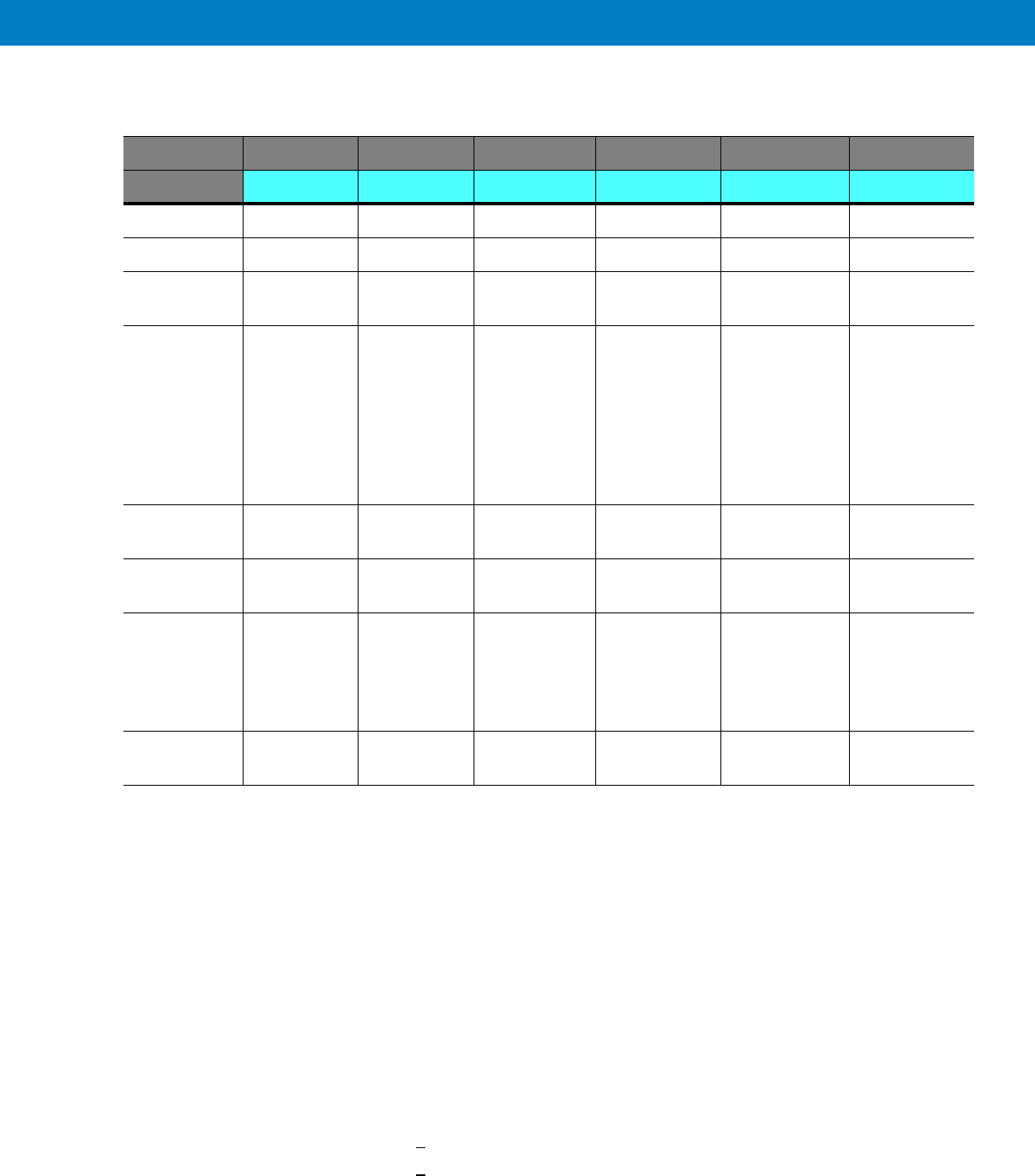
LEDs
Operating Temperature
Power
LED Name Power LAN LTE EVDO WiFi GPS
LED Status
OFF Power off No link Off Off Off Off
Solid Green Power on Link is on Connected Connected Available Tracking
Blinking
Green
Powering up TX/RX
Activity
Connecting/
Registering
Connecting/
Registering
TX/RX Activity --
Solid Orange No Ignition
The user
turns the
power On
(power
button
pressed) but
ignition is off.
-- -- -- -- --
Blinking
Orange
-- -- Searching for
signal
Searching for
signal
-- Searching for
signal
Solid Red -- -- Problem/
Overheat
Problem/
Overheat
Problem/
Overheat
Problem
Blinking Red Standby
External
power is
connected to
the system.
-- -- -- -- --
Rapid
Blinking Red
Problem SIM door is
open
Ambient temperature -30°C to +60°C
Input Voltage 11 to 16.60 VDC
RF Power Modes
LTE
EVDO
WiFi
Pout = 23.5 dBm
Pout = 23.5 dBm
Pout = 12.5 dBm
Power Consumption Amplifiers are Class AB.
Modem Standby < 0.3 A RMS
Modem Transmit < 1 A RMS

Specifications A - 3
Main Antenna
LTE
EVDO
GPS
Diversity Antenna
Type Sleeve Dipole
Frequency 746 - 798 MHz
Physical Texin 285 and Geloy XP4025 UV
Impedance 50 Ohms (nominal)
Polarization Vertical Linear
Height 17 inches (43cm)
Azimuth pattern Omni-directional
Elevation beamwidth 60 deg
Type Folded monopole
Frequency 821 - 896MHz, 1850 - 1990MHz
Physical PCB
Impedance 50 Ohm
Polarization Linear vertical
Height 65mm
Azimuth pattern Omni-directional
Elevation beamwidth 800MHz band - 60deg, 1900MHz band 40deg.
Type Active patch antenna
Frequency 1575.42 MHz
Impedance 50 Ohms (nominal)
Polarization Circular RHCP
System Gain (including cable) 11 dB
Type Wideband folded Monopole
Frequency 746 - 2500 MHz
Physical Fiberglass UV protected
Impedance 50 Ohms (nominal)
Polarization Vertical Linear
Height 1.77 inches (4.5Cm)

RF Characteristics
Azimuth pattern Omni-directional
Elevation beamwidth 35 deg
Frequency
LTE
EVDO BC0
EVDO BC1
WiFi
746-756 MHz, 777-787 MHz
758-768 MHz, 788-798 MHz
824-849 MHz, 869-894 MHz
1850-1910 MHz, 1930-1990 MHz
2401-2472 MHz
Bandwidth
LTE 5 MHz
10 MHz
EVDO 1.3 MHz
WiFi 20 MHz (802.11b/g)
Output transmit power
LTE 23.5 dBm
EVDO 23.5 dBm
WiFi 12.5 dBm
Receiver sensitivity
LTE 10 MHz -94dBm
5 MHz -97 dBm
EVDO -105.5 dBm
WiFi (802.11g) -87 dBm
Frequency Stability
LTE +/- 2.5 ppm
EVDO BC0 +/- 300 Hz
BC1 +/- 150 Hz
WiFi +/- 20 ppm
Appendix B Reference
Replacement Parts
Replace damaged parts with identical replacement parts.
For complete information on ordering required parts and kits, contact your local customer service representative.
Replacement Parts List
Kit/Part Number Description
Antennas
FAF5266A Main Antenna
FTN7651A Diversity Antenna
Bracket, Screws & Washers
0312002B14 Mounting Screw, Bracket to Car, 8
03013013001 Mounting Screw, VSM to Bracket, 8
0487779V56 Flat Washer, VSM to Bracket, 8
0487623U12 Spring Washer, VSM to Bracket, 8
07013065001 Bracket, 2
Cables
3071815Y61 LAN/Ethernet Cable (177”/450 cm)
30013060001 DC Power & Ignition Cable (177”/450 cm)

B - 2 VM L700 Installation Guide
Kit Replacement Parts List
Kit/Part Number Description
F4080A VML700, LTE VSM Modem

6802987C90-A June 2011
MOTOROLA and the Stylized M Logo and Symbol and the Symbol logo are registered in the U.S. Patent and Trademark Office.
All other product or service names are the property of their respective owners.
© Motorola, Inc. 2010
@6802987C01@