Motorola Solutions 92FT7060 VML750 RF Data Radio Modem User Manual
Motorola Solutions, Inc. VML750 RF Data Radio Modem Users Manual
Contents
- 1. Installation Guide
- 2. Safety Leaflet
- 3. Users Manual
Users Manual

VML750—LTEVehicularSubscriber
Modem(VSM)InstallationGuide
©July2014MotorolaSolutions,Inc.6802988C54-B
AllRightsReservedJuly2014

Copyrights
TheMotorolaproductsdescribedinthisdocumentmayincludecopyrightedMotorolacomputerprograms.LawsintheUnitedStatesandothercountries
preserveforMotorolacertainexclusiverightsforcopyrightedcomputerprograms.Accordingly,anycopyrightedMotorolacomputerprogramscontainedin
theMotorolaproductsdescribedinthisdocumentmaynotbecopiedorreproducedinanymannerwithouttheexpresswrittenpermissionofMotorola.
©2014MotorolaSolutions,Inc.AllRightsReserved
Nopartofthisdocumentmaybereproduced,transmitted,storedinaretrievalsystem,ortranslatedintoanylanguageorcomputerlanguage,inanyformorby
anymeans,withoutthepriorwrittenpermissionofMotorolaSolutions,Inc.
Furthermore,thepurchaseofMotorolaproductsshallnotbedeemedtogranteitherdirectlyorbyimplication,estoppelorotherwise,anylicenseunderthe
copyrights,patentsorpatentapplicationsofMotorola,exceptforthenormalnonexclusive,royalty-freelicensetousethatarisesbyoperationoflawinthesale
ofaproduct.
Disclaimer
Pleasenotethatcertainfeatures,facilities,andcapabilitiesdescribedinthisdocumentmaynotbeapplicabletoorlicensedforuseonaparticularsystem,or
maybedependentuponthecharacteristicsofaparticularmobilesubscriberunitorconfigurationofcertainparameters.PleaserefertoyourMotorolacontact
forfurtherinformation.
Trademarks
MOTOROLA,MOTO,MOTOROLASOLUTIONS,andtheStylizedMLogoaretrademarksorregisteredtrademarksofMotorolaTrademarkHoldings,LLC
andareusedunderlicense.Allothertrademarksarethepropertyoftheirrespectiveowners.
EuropeanUnion(EU)WasteofElectricalandElectronicEquipment(WEEE)directive
TheEuropeanUnion'sWEEEdirectiverequiresthatproductssoldintoEUcountriesmusthavethecrossedouttrashbinlabelontheproduct(orthepackage
insomecases).
AsdefinedbytheWEEEdirective,thiscross-outtrashbinlabelmeansthatcustomersandend-usersinEUcountriesshouldnotdisposeofelectronicand
electricalequipmentoraccessoriesinhouseholdwaste.
Customersorend-usersinEUcountriesshouldcontacttheirlocalequipmentsupplierrepresentativeorservicecentreforinformationaboutthewastecollection
systemintheircountry.

Document
History
DocumentHistory
■■■■■■■■■■■■■■■■■■■■■■■■■■■■■■■■■■■■■■■■■■■■
■
■
■
■
EditionDescriptionDate
Release1.0FirstreleaseofVML750—LTEVehicularSubscriber
Modem(VSM)InstallationGuide.
April2014
Release2.0SecondreleaseofVML750—LTEVehicularSubscriber
Modem(VSM)InstallationGuide.
July2014
6802988C54-BJuly2014i

Table
of
Contents
Contents
■■■■■■■■■■■■■■■■■■■■■■■■■■■■■■■■■■■■■■■■■■■■
■
■
■
■
VML750—LTEVehicularSubscriberModem(VSM)InstallationGuide
NotationalConventions......................................-xii
RequiredDocumentsforcompleteVSMDeployment........................-xiii
MotorolaSolutionsSupportCenter.................................-xiv
SupportCenter........................................-xiv
NorthAmericaPartsOrganization...............................-xiv
Safety..............................................-xiv
FCCInterference.........................................-xv
LegalNotice...........................................-xv
Chapter1:VML750Description
TheVML750Unit........................................1-1
Modem..............................................1-2
ConnectorPanel..........................................1-3
ConnectorPanelforB20LTEOnlyConfiguration..........................1-4
LEDIndicatorPanelwithPowerButtonandSIMCardDoor.....................1-5
PowerButton...........................................1-5
SIMCard.............................................1-6
Chapter2:VML750Installation
UnpackingandInspectingtheShipment..............................2-1
SafetyandGeneralInformation..................................2-1
PlanningtheInstallation......................................2-3
InstallationConstraints....................................2-3
CablesRouting........................................2-5
DrillingHoles........................................2-5
ToolsandEquipment.....................................2-5
Antennas.............................................2-6
AntennasforLTEB14+VzW.................................2-6
AntennaforConfigurationSupportingLTEPrivateNetworkonWW AN1...........2-6
AntennaConfigurationforLTEPublicNetworkonWWAN2................2-7
AntennasforB20LTEonlyConfiguration...........................2-8
MainAntenna......................................2-8
DiversityAntenna....................................2-8
Cables..............................................2-9
MountingBrackets........................................2-11
ModemInstallationProcess....................................2-12
AntennaMounting........................................2-12
SpecialAntennasInstallationConsiderations..........................2-13
6802988C54-BJuly2014iii
VML750—LTEVehicularSubscriberModem(VSM)InstallationGuide
GeneralAntennaInstallationSafetyConsiderations.....................2-13
MainAntenna......................................2-13
ModemInstallationProcedure...................................2-14
CablesRoutingandConnectionProcedure.............................2-15
DCPowerandIgnitionCableInstallation............................2-15
AntennaCablesInstallation(MainandDiversity)forLTEPrivateNetworkConfiguration.....2-16
AntennaCablesInstallation(MainandDiversity)forB20LTEonlyConfiguration........2-17
LAN/EthernetCableInstallation................................2-18
MicroUSBCableInstallation.................................2-18
SIMInstallation..........................................2-19
CryptRCardRemovalandInstallation...............................2-20
CapInstallation..........................................2-23
PoweringtheModemUp.....................................2-23
Chapter3:TroubleshootingtheVML750
Troubleshooting..........................................3-2
LEDIndicatorsFunctions.....................................3-5
Chapter4:UsingtheVML750
General..............................................4-1
AppendixA:Specifications
Physical.............................................A-1
CommunicationPorts.....................................A-1
RFPorts...........................................A-1
PowerPort..........................................A-2
LEDs.............................................A-2
OperatingTemperature....................................A-2
Power............................................A-2
RFCharacteristics.......................................A-2
AppendixB:Reference
ReplacementParts.........................................B-1
ReplacementPartsList....................................B-1
KitReplacementPartsList...................................B-2
ApprovedAntennasList....................................B-2
AntennasCablesReplacements................................B-2
AppendixC:LTE&LMRAntennasMountingRecommendations
PolicePatrolV ehicleAntennasLocationConsiderations—Overview.................C-1
PlanningAntennaMountingLocationonaPolicePatrolV ehicle...................C-2
iv6802988C54-BJuly2014

List
of
Figures
ListofFigures
■■■■■■■■■■■■■■■■■■■■■■■■■■■■■■■■■■■■■■■■■■■■
■
■
■
■
Figure1-1:VML750-GeneralView................................1-2
Figure1-2:ConnectorPanel....................................1-3
Figure1-3:ConnectorPanel....................................1-4
Figure1-4:LEDIndicatorsPanel..................................1-5
Figure2-1:VML750-SchematicCarInstallation..........................2-4
Figure2-2:VML750-Dimensions.................................2-4
Figure2-3:AntennaforConfigurationSupportingLTEPrivateNetworkonWW AN1.........2-7
Figure2-4:AntennaforLTEPublicNetworkonWW AN2......................2-7
Figure2-5:MainAntenna.....................................2-8
Figure2-6:DiversityAntenna-StandardConfiguration.......................2-9
Figure2-7:AvailableCables....................................2-9
Figure2-8:BracketDimensions..................................2-11
Figure2-9:MountingBrackets...................................2-14
Figure2-10:DCPowerandIgnitionCableRoutingIntoEngineCompartment............2-15
FigureC-1:PolicePatrolV ehicle—AntennasLocationSuggestion.................C-2
6802988C54-BJuly2014v


List
of
Procedures
ListofProcedures
■■■■■■■■■■■■■■■■■■■■■■■■■■■■■■■■■■■■■■■■■■■■
■
■
■
■
Procedure2-1:HowtoMounttheAntennas.............................2-13
Procedure2-2:HowtoInstalltheModemonaFlatSurface.....................2-14
Procedure2-3:HowtoInstalltheDCPowerandIgnitionCable...................2-15
Procedure2-4:HowtoInstallAntennaCables(MainandDiversity).................2-16
Procedure2-5:HowtoInstallAntennaCables(MainandDiversity).................2-17
Procedure2-6:HowtoInstalltheLAN/EthernetCable........................2-18
Procedure2-7:HowtoInstalltheMicroUSBCable.........................2-18
Procedure2-8:HowtoInstallaSIMCard..............................2-19
Procedure2-9:HowtoRemovetheCryptRCard..........................2-20
Procedure2-10:HowtoInstalltheCryptRCard...........................2-22
Procedure2-11:HowtoInstallCap(s)onUnusedConnector(s)....................2-23
Procedure2-12:HowtoPoweruptheModem...........................2-23
ProcedureC-1:PlanningAntennasLocationonaPolicePatrolVehicle................C-2
6802988C54-BJuly2014ix

About
This
Manual
VML750—LTEVehicularSubscriber
Modem(VSM)InstallationGuide
■■■■■■■■■■■■■■■■■■■■■■■■■■■■■■■■■■■■■■■■■■■■
■
■
■
■
WhatIsCoveredInThisManual?
TheVML750LTEVSMInstallationGuideprovidesgeneralinstructionsforinstalling,
operating,andtroubleshootingtheVML750.
Thisguideincludesthefollowingconfigurations:
•F0025(VML750)model-
◦FLN1057submodel—LTEB14+VzW.
◦FLN1310submodel—LTEB20.
6802988C54-BJuly2014xi
NotationalConventions
Theguideisorganizedasfollows:
•Chapter1,"VML750Description"providestheproductoverview.
•Chapter2,"VML750Installation"providesunpackinginstructionsandall
requiredproceduresforinstallingtheVML750.
•Chapter3,"TroubleshootingtheVML750"providesdetailsregardingpossible
malfunctionsthatmayoccurafterfirst-timeinstallationoftheVML750,their
probablecause,andtherecommendedcorrectiveactions.
•Chapter4,"UsingtheVML750"providesgeneralinformationregardingtheuseoftheVML750.
•AppendixA,"Specifications"providestheVML750modemspecifications.
•AppendixB,"Reference"providespartnumbersinformationforthemodemandantennas.
NotationalConventions
■■■■■■■■■■■■■■■■■■■■■■■■■■■■■■■■■■■■■■■■■■■■
■
■
Thefollowingconventionsareusedinthisdocument:
•Italicsareusedtohighlightthefollowing:
◦Chaptersandsectionsinthisandrelateddocuments
◦Dialogbox,windowandscreennames
◦Drop-downlistandlistboxnames
◦Checkboxandradiobuttonnames
•Boldtextisusedtohighlightthefollowing:
◦Keynamesonakeypad
◦Buttonnamesonascreen
•bullets(•)indicate:
◦Actionitems
◦Listsofalternatives
◦Listsofrequiredstepsthatarenotnecessarilysequential
•Sequentiallists(e.g.,thosethatdescribestep-by-stepprocedures)appearasnumberedlists.
xii6802988C54-BJuly2014

VML750—LTEV ehicularSubscriberModem(VSM)InstallationGuideRequiredDocumentsforcompleteVSMDeployment
RequiredDocumentsforcompleteVSMDeployment
■■■■■■■■■■■■■■■■■■■■■■■■■■■■■■■■■■■■■■■■■■■■
■
■
Tocompletethefulldeploymentofthemodem,youmayneedthefollowingdocuments:
•InformationrelatedtoVML750configurationintheVML750ConfigurationGuideP/N
6802988C55locatedat:https://businessonline.motorolasolutions.com
•InformationrelatedtoVML750monitoringcanbefoundintheVML750LTEV ehicle
SubscriberModem(VSM)StatusUtilityQuickReferenceGuideP/N6802988C79.
•InformationrelatedtothedevicelicensingcanbefoundintheDeviceLicensingQuick
ReferenceGuideP/N6871024P25locatedat:https://businessonline.motorolasolutions.com
6802988C54-BJuly2014xiii

MotorolaSolutionsSupportCenter
MotorolaSolutionsSupportCenter
■■■■■■■■■■■■■■■■■■■■■■■■■■■■■■■■■■■■■■■■■■■■
■
■
SupportCenter
TheMotorolaSolutionsSupportCenter(SSC)istheprimaryMotorolaSolutionssupportcontact.Call:
•Priortoanysoftwarereload.
•ToconfirmtroubleshootingresultsandanalysispriortoremovingandreplacingaField
ReplaceableUnit(FRU)andFieldReplaceableEntity(FRE)torepairthesystem.
For...Phone
Domesticcalls800–221–7144
Internationalcalls302–444–9800
NorthAmericaPartsOrganization
Forassistanceinorderingreplacementpartsoridentifyingapartnumber,contactMotorola'sparts
organization.
PleaserememberthatyourfirstresponsewhentroubleshootingyoursystemistocalltheMotorolaSSC.
For...Phone
PhoneOrders800–422–4210(USandCanadaorders)
302-444-9842(Internationalorders)
FaxOrders800–622–6210(USandCanadaorders)
Helpidentifyinganitemorpartnumber800–422–4210andselectchoice3fromthemenu.
Safety
■■■■■■■■■■■■■■■■■■■■■■■■■■■■■■■■■■■■■■■■■■■■
■
■
Beforeinstalling/usingthisproduct,theinstaller/operatormustbefamiliarwiththeRFenergy
awarenessinformationandoperatinginstructionsinthe“ProductSafetyandRFEnergyExposure
BookletforMobileTwo-WayRadiosInstalledinV ehiclesorasFixedSiteControlStations”
enclosedwiththeVML750LTEVSM(MotorolaPublicationpartnumber6881095C99)toensure
compliancewithRadioFrequency(RF)energyexposurelimits.
xiv6802988C54-BJuly2014

VML750—LTEV ehicularSubscriberModem(VSM)InstallationGuideFCCInterference
FCCInterference
■■■■■■■■■■■■■■■■■■■■■■■■■■■■■■■■■■■■■■■■■■■■
■
■
ThisdevicecomplieswithPart15oftheFCCRules.Operationissubjecttothefollowingtwoconditions:
•Thisdevicemaynotcauseharmfulinterference.
•Thisdevicemustacceptanyinterferencereceived,includinginterference
thatmaycauseundesiredoperation.
Changesormodificationsmadetothisproduct,notexpresslyapprovedbyMotorola,will
voidtheuser'sauthoritytooperatetheequipment,perFCCRulePart15.21.
LegalNotice
■■■■■■■■■■■■■■■■■■■■■■■■■■■■■■■■■■■■■■■■■■■■
■
■
TheVML750OSSlegalnoticewillbeprovidedbyMotorolaperrequest.
6802988C54-BJuly2014xv
LegalNotice
Thispageintentionallyleftblank.
xvi6802988C54-BJuly2014

Chapter
1
VML750Description
■■■■■■■■■■■■■■■■■■■■■■■■■■■■■■■■■■■■■■■■■■■■
■
■
■
■
TheVML750Unit
■■■■■■■■■■■■■■■■■■■■■■■■■■■■■■■■■■■■■■■■■■■■
■
■
TheMotorolaVML750-LTEV ehicularSubscriberModem(VSM)isalow-powermodem.
ThefollowingmodelsandtheirSKUareavailable:
•F0025family:
◦FLN1057:Amulti-modemodemthathastheabilitytooperateinLTEBand14/13
and3GEvDoBC0/BC1.ThemodemsupportsWiFiasclientandAPaswellas
GPSforlocationandsupportfordataencryption(CyrptR).
◦FLN1310:Amulti-modemodemthathastheabilitytooperateinLTE
Band20.ThemodemsupportsWiFiasclientandAPaswellasGPSfor
locationandsupportfordataencryption(CyrptR).
SeeFigure1-1.
6802988C54-BJuly20141-1
ModemChapter1:VML750Description
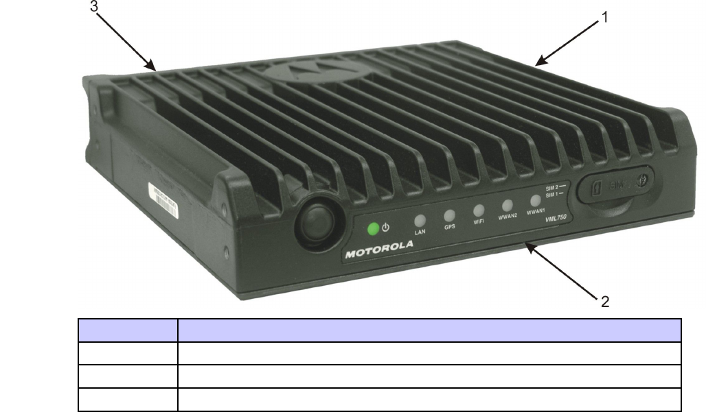
Figure1-1VML750-GeneralView
Item#Description
1Modem
2LEDIndicatorPanel(FrontPanel)
3ConnectorPanel(BackPanel-notshown)
FordetailedspecificationsoftheVML750unit,seeAppendixA,"Specifications".
Modem
■■■■■■■■■■■■■■■■■■■■■■■■■■■■■■■■■■■■■■■■■■■■
■
■
Themodemhasaconnectorpanel(backpanel)andaLEDIndicatorpanelwithaPowerbutton(frontpanel).
1-26802988C54-BJuly2014
VML750—LTEV ehicularSubscriberModem(VSM)InstallationGuideConnectorPanel
ConnectorPanel
■■■■■■■■■■■■■■■■■■■■■■■■■■■■■■■■■■■■■■■■■■■■
■
■
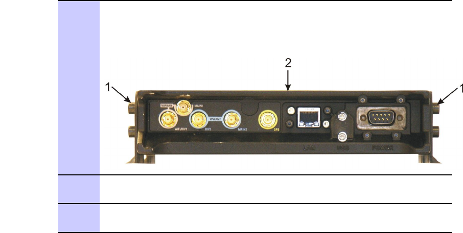
TheVML750Connectorpanelconsistsofthefollowing(seeFigure1-2):
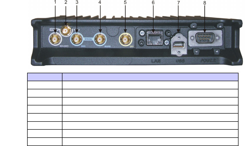
Figure1-2ConnectorPanel
Item#Description
1RFSMAfemaletypeconnector(WW AN1DIV/WiFi)
2RFSMAfemaletypeconnector(WWAN1main)
3RFSMAfemaletypeconnector(WWAN2DIV)
4RFSMAfemaletypeconnector(WW AN2)
5RFSMAfemaletypeconnector(GPS)
6LAN/Ethernetcommunicationconnector(RJ45)
7MicroABtypeconnector(USB2.0)
8DCpowerandGPIOD-type,9–pinconnector
6802988C54-BJuly20141-3
ConnectorPanelforB20LTEOnlyConfigurationChapter1:VML750Description
ConnectorPanelforB20LTEOnlyConfiguration
■■■■■■■■■■■■■■■■■■■■■■■■■■■■■■■■■■■■■■■■■■■■
■
■
TheVML750Connectorpanelconsistsofthefollowing(seeFigure1-3):
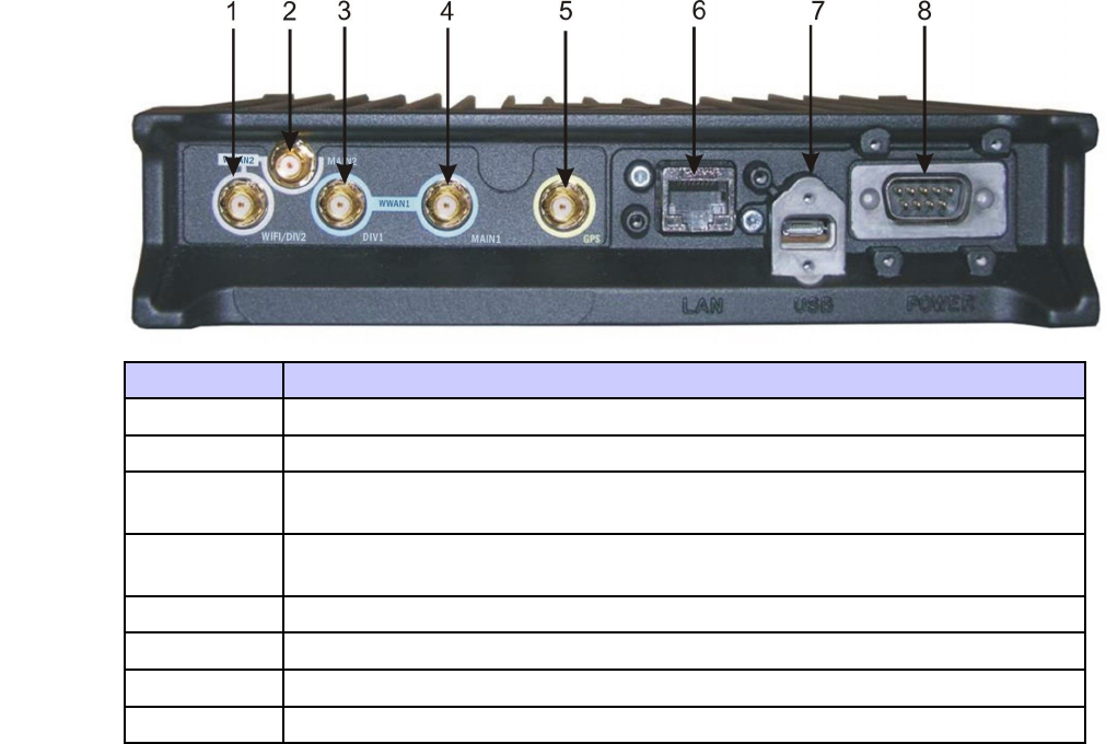
Figure1-3ConnectorPanel
Item#Description
1RFSMAfemaletypeconnector(WW AN2DIV/WiFi)
2RFSMAfemaletypeconnector(WWAN2main)
3RFSMAfemaletypeconnector(WWAN1DIV1)(doesnotapplyforB20LTEonly
configuration)
4RFSMAfemaletypeconnector(WW AN1MAIN1)(doesnotapplyforB20LTEonly
configuration)
5RFSMAfemaletypeconnector(GPS)
6LAN/Ethernetcommunicationconnector(RJ45)
7MicroABtypeconnector(USB2.0)
8DCpowerD-type,9–pinconnector
1-46802988C54-BJuly2014
VML750—LTEV ehicularSubscriberModem(VSM)InstallationGuideLEDIndicatorPanelwithPowerButtonandSIMCardDoor
LEDIndicatorPanelwithPowerButtonandSIMCardDoor
■■■■■■■■■■■■■■■■■■■■■■■■■■■■■■■■■■■■■■■■■■■■
■
■
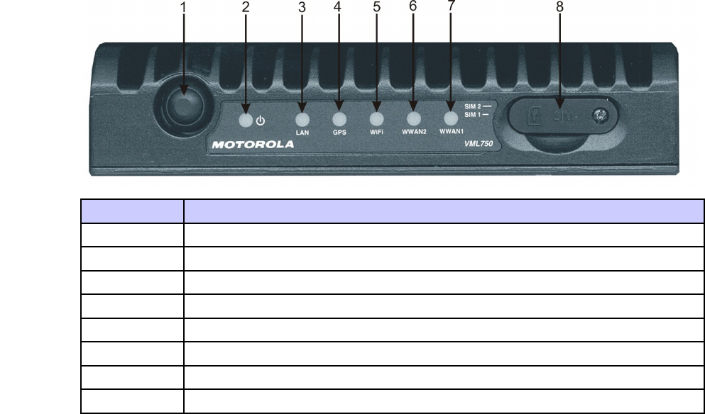
AsetofsixLEDsisusedfordiagnosticsandtestingoftheunit(seeFigure1-4).
Figure1-4LEDIndicatorsPanel
Item#Description
1PowerButton
2PowerIndicator
3LAN
4GPS
5WiFi
6WWAN2
7WWAN1(doesnotapplyforB20LTEonlyconfiguration)
8SIMCardDoor
PowerButton
■■■■■■■■■■■■■■■■■■■■■■■■■■■■■■■■■■■■■■■■■■■■
■
■
ThePowerbuttonisusedtoturntheVML750OnorOffwhenIgnitionSenseisdisabled.IftheIgnitionSenseis
enabled,youalsoneedtoturnyourvehicleignitionswitchtoOn.Thisbuttonisalsousedtoapplyfactoryreset.
6802988C54-BJuly20141-5

SIMCardChapter1:VML750Description
SIMCard
■■■■■■■■■■■■■■■■■■■■■■■■■■■■■■■■■■■■■■■■■■■■
■
■
IfyourLTEmodemisintendedtohomeonyourprivateMotorolaLTEnetwork,youareprovidedwitha
MotorolaLTESIMcard(tobeinsertedintoSIM1slot).IfyourLTEmodemisintendedtohomeonapublic
carrierLTEnetwork,youneedtoobtainaSIMcardfromthatpubliccarrierandinsertintoSIM2slot.The
SIMcardmustbeinsertedwiththemetalleadsfacingdownandthenotchedcornerontheleft.
TheWiFimodemisstilloperationalwithoutaSIMcard.
•WiFimustbeconfiguredpriortouse.RefertoVML750ConfigurationGuide(6802988C55)
locatedinhttps://businessonline.motorolasolutions.comforconfigurationprocedure.
1-66802988C54-BJuly2014

Chapter
2
VML750Installation
■■■■■■■■■■■■■■■■■■■■■■■■■■■■■■■■■■■■■■■■■■■■
■
■
■
■
UnpackingandInspectingtheShipment
■■■■■■■■■■■■■■■■■■■■■■■■■■■■■■■■■■■■■■■■■■■■
■
■
Unpackyourequipmentandcheckthecontentstoensurethatyouhavereceivedallthespecifieditems.
Thoroughlyinspecttheequipmentforshippingdamageassoonaspossibleafterdelivery.Reportany
damageyoufindtoyourMotorolaCustomerServicerepresentativeimmediately.
SafetyandGeneralInformation
■■■■■■■■■■■■■■■■■■■■■■■■■■■■■■■■■■■■■■■■■■■■
■
■
AproperlyinstalledVML750unitminimizesservicecalls.WhenmountingtheVML750
unitcomponents,considerthefollowingfactors:
ThisdevicerequiresprofessionalinstallationtosatisfycompliancewithFCCrequirements.
•Themountingsurfacemusthavesufficientstrengthtosupporttheequipmentbeing
mountedandtopreventitfrombecominglooseovertime.
•Donotattachcomponentstoanypartofthevehiclesubjectedtoexcessivevibration.
•DonotmounttheVML750unitonaflatsurfacewheretheunitcould
becomepartiallysubmersedinwater.
•Theproposedlocationoftheequipmentbeingmountedorwires/cablesattached
mustnotinterferewithdriver/passengerseatingorlegspace.
6802988C54-BJuly20142-1
SafetyandGeneralInformationChapter2:VML750Installation
•Selectalocationsuchthatheatfromtheunitdoesnotdamageanywiringorany
otherplasticorheat-sensitivepartsoftheautomobile.
•Usethesuppliedmountinghardware.
•LeavesufficientspacearoundtheVML750unitforairflowandinstallation.
•Selectalocationthatpermitsroutingthecablesasdirectlyaspossible.
•Ensurethatthecablesarenotstretched,andnotsubjecttoheatfromtheengine,
transmissionhousing,orheatingducts.
•Crimpconnectorssecurely.
•Donotruncablesoversharpedgesthatmaycauseexcessivewearor
chaffingofthecableinsulation.
•Donotinstallcomponentsinlocationswheretheymaycauseinterference
totheoperationofthevehicle'scontrols.
•Onlyqualifiedpersonnelmayinstallcommunicationequipment.
•Ensuresecuretighteningofcableconnectors.
Installthisproductinavehicleinaccordancewiththevehiclemanufacturer’sguidelinesandthe
instructionsdetailedinthismanual.UseonlytheMotorolapartsspecifiedinthismanual.
Checktherequiredmountinglocations.Itmightbenecessarytopenetratethefirewalltoreachthebattery.
Beforedrillingcommences,ensurecableclearanceontheoppositesideofthefirewallanddonotinstall
thevehicle’sElectronicControlModules(ECM’s)ontheoppositesideofthefirewall.Protectthecable
whereitpassesthroughthefirewallbyusingagrommetorsimilarprotectivemeasures.
InstallingtheVML750attheendofthevehicleabovetheexhaust
pipemaycausetheVML750tooverheat.
VEHICLESEQUIPPEDWITHAIRBAGS
Anairbaginflateswithgreatforce.DONOTplaceobjects,including
communicationsequipment,intheareaovertheairbagorintheairbag
deploymentarea.Ifthecommunicationequipmentisimproperlyinstalled
andtheairbaginflates,thiscouldcauseseriousinjury.
Ifnecessary,contactthevehiclemanufacturerforairbaginformationspecifictothevehicle.
Verifythatnoneofthevehicle’ssystemsareaffectedbyuseofthe
unit,e.g.cruisecontrol,ABSbreaking,tractioncontrol,engine
management,directionindicators,lights,etc.
2-26802988C54-BJuly2014

VML750—LTEV ehicularSubscriberModem(VSM)InstallationGuidePlanningtheInstallation
Useexistingopeningsthroughthefirewalltoavoiddrilling.Ifdrilling
isamust,verifynottodamagetheVehicleElectronicControlModules
(ECM’s),fuellines,brakelines,and/orcablelooms.
Forvehiclesequippedwithelectronicbrakingsystems,see“ANTI-SKIDBRAKING
PRECAUTIONS”,Motorolapublication68P81109E34.
Itismandatorythatmodemsinstalledinvehiclesfuelledbyliquefiedpetroleum
gasconformtotheNationalFireProtectionAssociationstandardNFPA58,which
appliestovehicleswithaliquidpropane(LP)gascontainerinthetrunkorother
sealedoffspacewithintheinteriorofthevehicle.TheNFPA58requiresthe
following:
(1)ThespaceinwhichtheLPgascontaineranditsfittingsarelocatedmustbe
isolatedbyasealfromthespacecontainingmodemequipment.
(2)Removable(outside)fillingconnectionsshallbeused.
(3)Thecontainerspaceshallbeventedtotheoutside.
PlanningtheInstallation
■■■■■■■■■■■■■■■■■■■■■■■■■■■■■■■■■■■■■■■■■■■■
■
■
Planningisthekeytofast,easyandsafeinstallation.
Takethefollowingpointsintoconsiderationwhenselectingalocationandplanningtheinstallation.
InstallationConstraints
RefertotheSafetyInstructionsin“ProductSafetyandRFEnergyExposureBookletforMobileTwo-Way
RadiosInstalledinVehiclesorasFixedSiteControlStations”P/N6881095C99.
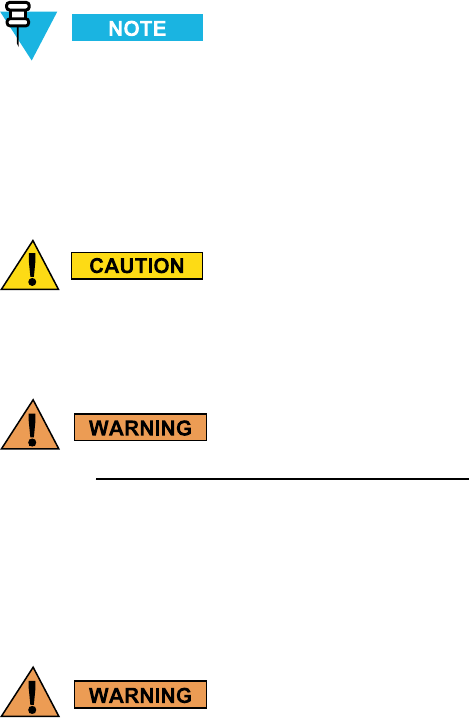
TheVML750mustbeinstalledinthecar’strunk,onthefloororthesidewalls
(coolingfinsfacingup,ortotheside).
6802988C54-BJuly20142-3
InstallationConstraintsChapter2:VML750Installation
TheVML750mustnotbeinstalledwiththecoolingfinsfacingdown.Failuretocomply
maycauseoverheatingproblemsandperformancedegradation.
Figure2-1showsaschematicVML750installationinacar.
Figure2-1VML750-SchematicCarInstallation
Beforebeginningtheinstallationprocessmakesurethatthespaceavailableattheinstallation
siteisadequateforthemodemanditsaccessories.Eachinstallationconfigurationrequires
adifferentareaformountingthemodemwithoutobstruction.
Whenchoosingalocation,ensureeasyinstallationandreplacementoftheunit.
Figure2-2givestheVML750dimensions.
Figure2-2VML750-Dimensions
2-46802988C54-BJuly2014

VML750—LTEV ehicularSubscriberModem(VSM)InstallationGuideCablesRouting
CablesRouting
•Beforerunningawireordrillingahole,inspectthevehicleanddeterminehowandwhere
youintendtomounttheantenna,modem,andtheinput/outputdevice.
•Planwireandcableroutingtoprovidemaximumprotectionfromoverheating,
batteryacid,movingpartsandsharpedges.
•Keepcablesawayfromignitioncircuitstoreducenoisepickupintheradioequipment.
•Verifythatthecablesareofsufficientlength.Donotconnecttwoshortlengthswith
asplice;doingsoresultsinpowerloss.Refrainfromlooseexcessinthecables,
butleaveenoughslacktoallowre-connectionifnecessary.
•Donotruncablesexternallyorunderneathfloormats.
•Donotlocatecableswherethedriverorpassengerscankickthemorwherethey
caninterferewithoperationofthedriver’sfootpedals.
•Whenroutingthecables,refrainfromcreatingsharpbendsorkinks.
Fordetailedantennacablesroutinginstructions,refertotheInstallation
Guidesuppliedwitheachantenna.
DrillingHoles
•Wherepossible,useexistingholesinthefirewall,thetrunkwallandthe
channelsaboveorbeneaththedoors.
•Ifyoumustdrillholes,verifynottodamageotherwiring,breaklinesorfuellines.
•Whendrillingaholeintheroof,takecarenottosnagtheroofliner.
•Topreventrustingafterdrilling,removeallmetalburrsandresidue,andcompletely
cleantheareatoensuretheremovalofallsteeldust.
•Insertrubbergrommetsinalldrilledholestoprotectcables,exceptforantennascables.
ToolsandEquipment
•#2Phillipsscrewdriver
•Electricdrillanddrillbitset
•X-actoknifeorequivalent
•Wirestrippers
•Longnosepliers
•Smallsidecutters
•Crimpingtool
6802988C54-BJuly20142-5

AntennasChapter2:VML750Installation
•Wrenchset,including8mmfortraytounitattachment
•Crescentwrench
•Spannerwrench
•3mmAllenwrenchsetforunittotrayattachment
•No.8Torxscrewdriver
•Electricaltape
Antennas
■■■■■■■■■■■■■■■■■■■■■■■■■■■■■■■■■■■■■■■■■■■■
■
■
ThefollowingantennasdescribedareforvariousVSMfamilyproducts.
AntennasforLTEB14+VzW
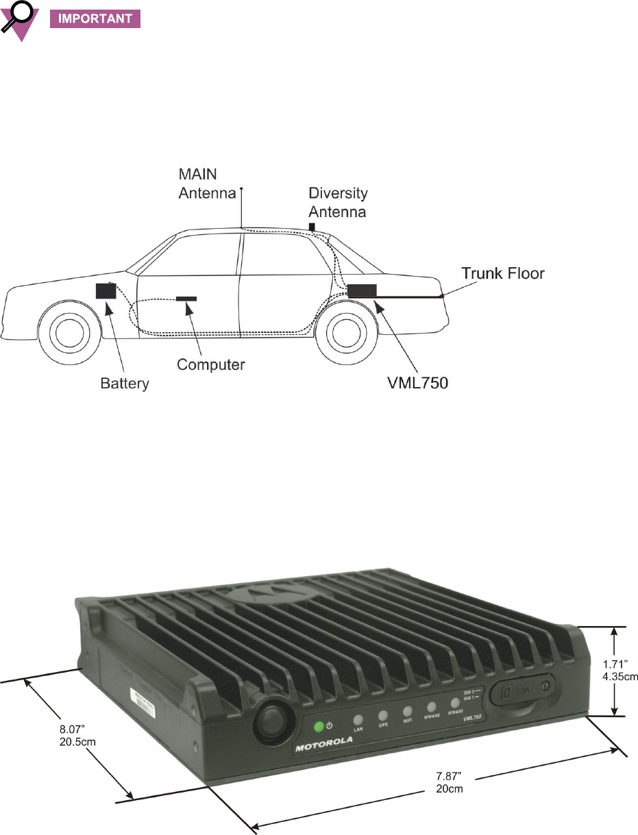
AntennaforConfigurationSupportingLTEPrivateNetworkonWWAN1
TheantennaisusedtoenhancethereceptioncapabilityinpoorreceptionareasandalsotosupportMultiple
InputMultipleOutput(MIMO)modesforLTE.
Theantennacanbeprovidedwith12ftor17ftcoaxialcable.
Theantennaisconstructedofthreeantennas:
•ExternalWhip—formain(tobeconnectedtoWW AN1main)
•Internalantenna-fordiversityandWiFi(tobeconnectedtoWWAN1diversity)
•GPSactiveantenna(tobeconnectedtoWW AN1GPSport)
Theantennaisprovidedwiththreeshortflexiblecoaxialcables(threads)comingout
oftheantennabottomside(seeFigure2-3).
2-66802988C54-BJuly2014
VML750—LTEV ehicularSubscriberModem(VSM)InstallationGuideAntennaConfigurationforLTEPublicNetworkonWW AN2
Figure2-3AntennaforConfigurationSupportingLTEPrivateNetworkonWWAN1
AntennaConfigurationforLTEPublicNetworkonWWAN2
Twoidenticalantennasareused;oneforthemainandonefordiv.
Theantennacanbeprovidedwith12ftor17ftcoaxialcable.
Figure2-4AntennaforLTEPublicNetworkonWWAN2
6802988C54-BJuly20142-7

AntennasforB20LTEonlyConfigurationChapter2:VML750Installation
AntennasforB20LTEonlyConfiguration
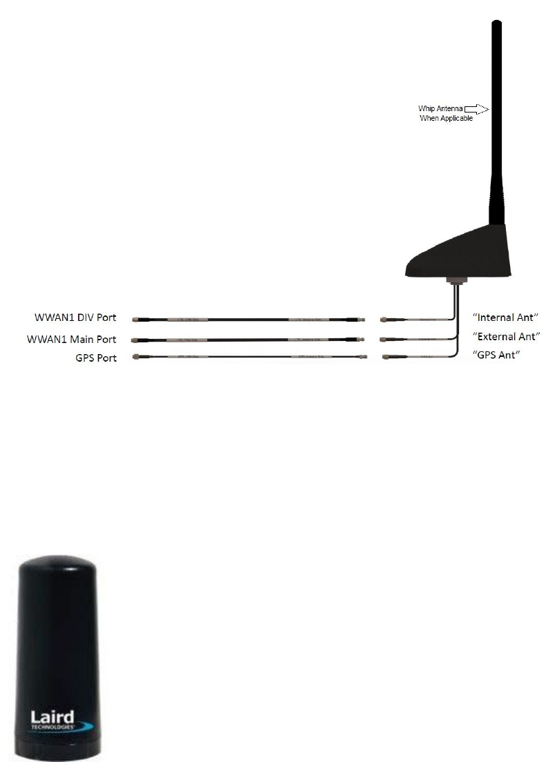
MainAntenna
TheMainantennaisusedtoenhancethereceptioncapabilityinpoorreceptionareasandalso
tosupportMultipleInputMultipleOutput(MIMO)modesforLTE.
Theantennacanbeprovidedwith12ftor17ftcoaxialcable.
TheMainantennaisshowninFigure2-5.
Figure2-5MainAntenna
DiversityAntenna
Thediversityantennaisconstructedofthreeantennas.
•ExternalWhip—doesnotapplyforB20LTEonlyconfiguration
•InternalantennaforWWAN2diversityandWiFi(tobeconnectedtoWW AN2diversity)
•GPSactiveantenna(tobeconnectedtoGPSport)
Theantennaisprovidedwiththreeshortflexiblecoaxialcables(threads)comingoutoftheantenna
bottomside.Dependingontheantennaoptionpurchased,two12ftor17ftcoaxialcablesarealso
providedinordertoconnectbetweenthesethreadsandthemodemconnectors.Thecableswill
beconnectedtotheGPSandtotheWW AN2div.(seeFigure2-6).
BesuretousetheRG-174cabletoGPSport.
2-86802988C54-BJuly2014
CablesChapter2:VML750Installation
2-106802988C54-BJuly2014
VML750—LTEV ehicularSubscriberModem(VSM)InstallationGuideMountingBrackets
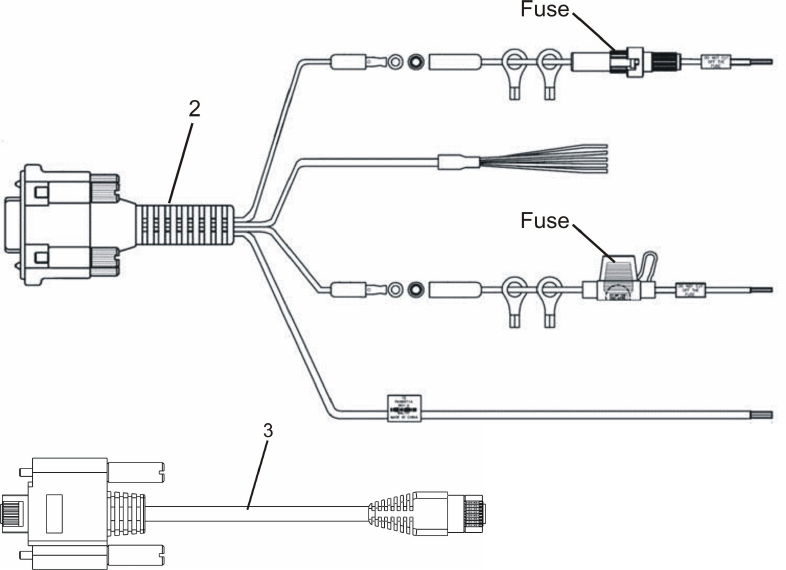
Item#Description
1DCPowerandIgnitioncable(P/NFKN8663)
2DCPowerandIgnitioncable+GPIO(P/NFKN8671)
3LAN/Ethernetcable(P/NFKN8570)
4MicroUSBcable(P/NFKN8703,canbepurchasedseparately)
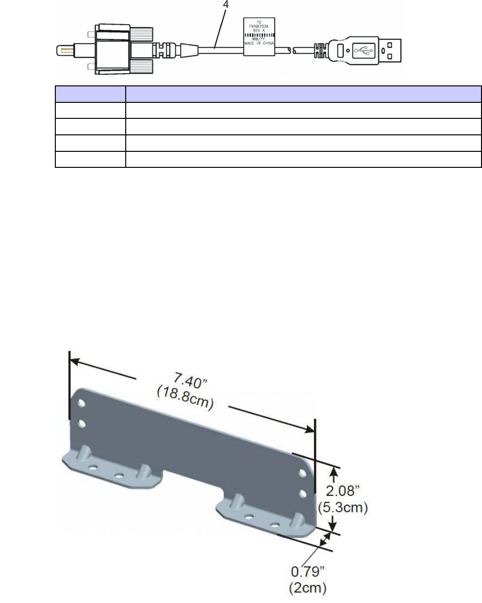
MountingBrackets
■■■■■■■■■■■■■■■■■■■■■■■■■■■■■■■■■■■■■■■■■■■■
■
■
Usethebrackets(2bracketsaresupplied)formountingtheVML750securelyonaflatsurface.
Figure2-8BracketDimensions
6802988C54-BJuly20142-11

ModemInstallationProcessChapter2:VML750Installation
ModemInstallationProcess
■■■■■■■■■■■■■■■■■■■■■■■■■■■■■■■■■■■■■■■■■■■■
■
■
Process2-1describesthestepsforthemodeminstallation.
Process2-1HowtoInstalltheVML750Modem
1Ensureadequatespacefortheinstallation.(See"PlanningtheInstallation"on
page2-3)
2Installtheantennas.(See"AntennaMounting"onpage2-12).Refertothe
InstallationGuidesuppliedwitheachantenna.
3Routethecables.(See"PlanningtheInstallation"onpage2-3and"Cables
RoutingandConnectionProcedure"onpage2-15).
4Installthebracketsandtheunit.(See"ModemInstallationProcedure"onpage
2-14).
5ConnecttheDCPowerandIgnitioncable.(See"DCPowerandIgnitionCable
Installation"onpage2-15).
6Connectthemainantennacables.(See"AntennaCablesInstallation(Mainand
Diversity)forLTEPrivateNetworkConfiguration"onpage2-16or"Antenna
CablesInstallation(MainandDiversity)forB20LTEonlyConfiguration"on
page2-17).
7ConnecttheLAN/Ethernetcable(see"LAN/EthernetCableInstallation"onpage
2-18)ortheMicroUSBcable(seeProcedure2-7,"HowtoInstalltheMicro
USBCable,"onpage2-18).
8Placecapsonunusedconnector(s).(See"CapInstallation"onpage2-23).
9PerformVML750Power-onprocess.(See"PoweringtheModemUp"onpage
2-23).
AntennaMounting
■■■■■■■■■■■■■■■■■■■■■■■■■■■■■■■■■■■■■■■■■■■■
■
■
Procedure2-1givesgeneralinstructionsformountingtheantennas.
2-126802988C54-BJuly2014
VML750—LTEV ehicularSubscriberModem(VSM)InstallationGuideSpecialAntennasInstallationConsiderations
Procedure2-1HowtoMounttheAntennas
1Mounttheantennasinaccordancewiththeinstructionsprovidedwitheachantenna
kitandwiththe“ProductSafetyandRFEnergyExposureBookletforMobile
Two-WayRadiosInstalledinV ehiclesorasFixedSiteControlStations”enclosed
withtheVML750LTEVSM(MotorolaPublicationpartnumber6881095C99).
SpecialAntennasInstallationConsiderations
GeneralAntennaInstallationSafetyConsiderations
Theantennasmustbeinstalledinalocationthatwillensureadistanceof
atleast8”(20cm)betweenanyofthemandanybystander.
IfyourvehicleisequippedwithPSNB(PublicSafetyNarrowBand)equipment,
specialattentionmustbetakenwheninstallingtheantennas.Aminimumdistance
of78”(198cm)mustbekeptinordertoensurecoexistencebetweenallsystems.
MainAntenna
Theantennamustbeinstalledonaflatmetalsurface(minimumsize24”(61cm)x24”(61cm)).
Themainantennamustbeinstalledonthevehicle’sroof,preferablyinthecenterfrontside
ofit.Makesurethatthevehicleroofmaterialismetal.Ifnot,usea2ftx2ftmetalground
planeandmounttheantennainitscenter.Forbestperformance,aminimumdistanceof
36”(91.44cm)mustbekeptbetweenthisantennaandanyotherantenna.
6802988C54-BJuly20142-13
ModemInstallationProcedureChapter2:VML750Installation
ModemInstallationProcedure
■■■■■■■■■■■■■■■■■■■■■■■■■■■■■■■■■■■■■■■■■■■■
■
■
Procedure2-2describeshowtoinstallthemodemonaflatsurface.
Procedure2-2HowtoInstalltheModemonaFlatSurface
1Positionthetwomountingbrackets(1)onbothsidesofthemodem(2)andfasten
using4screwseach.SeeFigure2-9.
Figure2-9MountingBrackets
2LocatetheVML750withthemountingbracketsattachedonthededicatedflat
surface.
3Centerpunchthemarkedspotsandfixthemodeminpositionusingtheself-drilling
suppliedscrews.
2-146802988C54-BJuly2014
VML750—LTEV ehicularSubscriberModem(VSM)InstallationGuideCablesRoutingandConnectionProcedure
CablesRoutingandConnectionProcedure
■■■■■■■■■■■■■■■■■■■■■■■■■■■■■■■■■■■■■■■■■■■■
■
■
DCPowerandIgnitionCableInstallation
Theunitisusedwithanegativegroundsystemonly.
TheFKN8663/FKN8671DCPowercableisequippedwitha5-Amperefuse(slow-blow).
Verifythatthevehicleelectricalsystemcansupportcurrentvalueslargerthanthat.
Insertthefuseintothefuseholderafterinstallationcompletionandaftercarefully
inspectingallconnections.
TheVML750supports12/24Vvehiclebatteries,i.e.13.8V±20%and
27.6V±20%DCvehiclebatteries.ConnectingtheVML750toahigher
voltagebatterysource(i.e.48V)maydamageit.
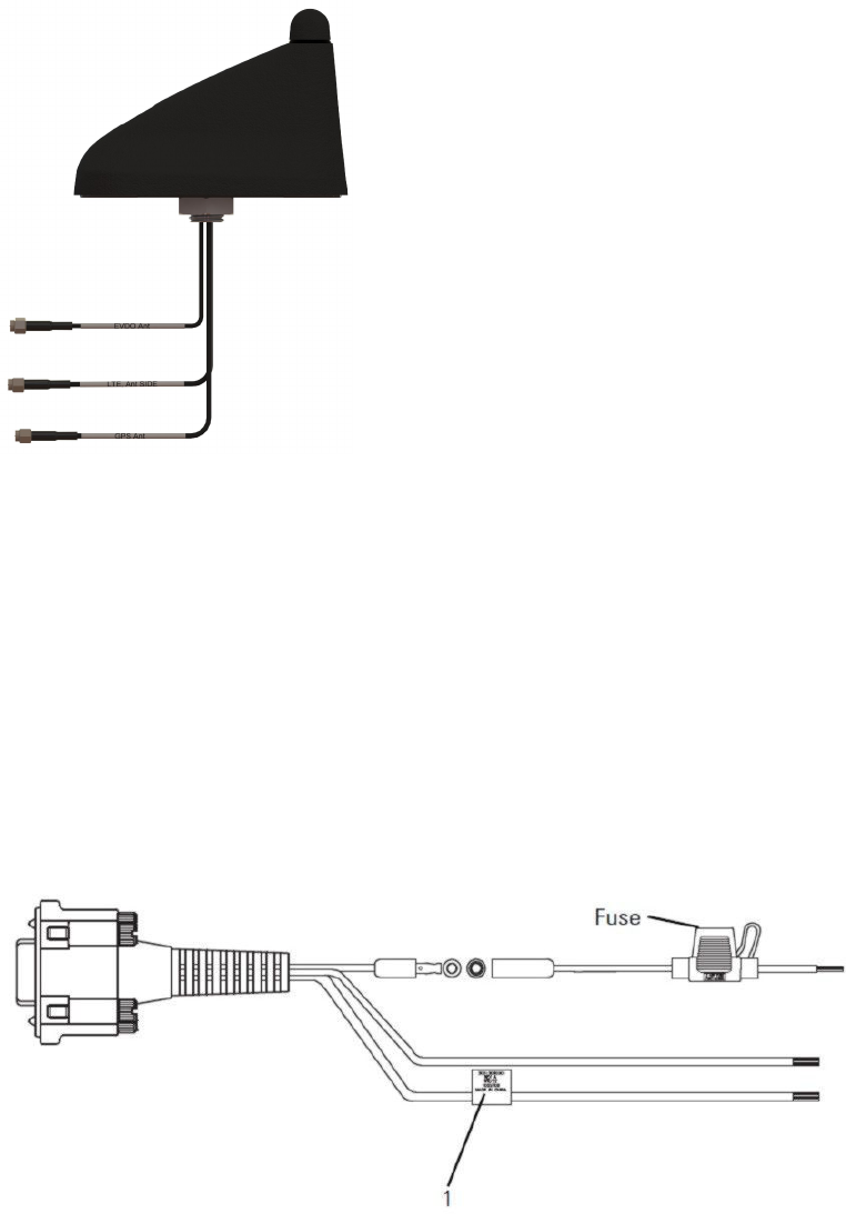
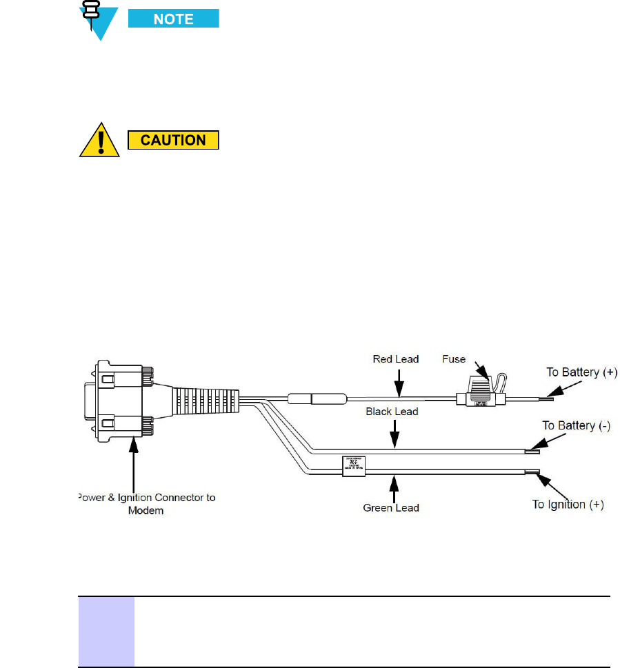
SeeFigure2-10beforeroutingorconnectingtheDCPowerandIgnitioncableandusethefollowingprocess.
Figure2-10DCPowerandIgnitionCableRoutingIntoEngineCompartment
Procedure2-3describeshowtoinstalltheDCpowerandignitioncable.
Procedure2-3HowtoInstalltheDCPowerandIgnitionCable
1Removethefusefromthefuseholder.RoutetheDCPowercableleadsthroughthe
firewallandintotheenginecompartment.Useanexistingopeningor,ifnecessary,
drilla2cm(26/32”)diameterholethroughthefirewall.Insertagrommetintothe
holetopreventdamagetotheDCPowercable.
6802988C54-BJuly20142-15

AntennaCablesInstallation(MainandDiversity)forLTEPrivateNetworkConfigurationChapter2:VML750Installation
Procedure2-3HowtoInstalltheDCPowerandIgnitionCable(Continued)
2Ontheenginesideofthefirewall,connecttheblackleadtothenegative(-)battery
terminal.
3Ontheenginesideofthefirewall,connectthered(A+)leadtothevehicle’sbattery
asfollows:
1.V erifythatthefuseholderisatadistanceof20-30cm(7.87-11.8”)awayfrom
theconnectionpoint,ensuringthatitisnotclosetoanyhotenginecomponent.
2.Mountthefuseholderusingtheprovidedmount,anddresswiresasnecessary.
Connecttheredleadplugadaptor(onthefuseholder)tothematchingreceptacle
ontheredleadoftheDCPowercable.
3.ConnecttheredleadoftheDCPowercabletothepositive(+)batteryterminal.
Cabletiethewireevery4”(10cm)alongitslength,donottietoexistingvehicle
cables
4.Insertthefuseintothefuseholder.
4Verifythatthecablesintheenginecompartmentdonotobstructanyofthevehicle
controlsortouchhotormoveablepartsoftheengine.
5Forignitioninstallation,performthefollowingsteps:
1.Consultthevehicledocumentationtolocatetheignitionwire.
2.V erifythatthevoltageishighwithignitionon,duringstart(cranking),
accessory,andwhilevehicleisrunning.Whentheignitionisoff,thevoltageiszero.
3.ConnectthegreenleadoftheDCPowercabletoignition(+).Cabletiethe
wireevery4”(10cm)alongitslength,donottietoexistingvehiclesystems.
6ConnecttheDCPowerandignitioncableconnectortoPOWERconnectoronthe
VML750Connectorpanel.Fastentheconnectorusingthefourfasteningscrews.
AntennaCablesInstallation(MainandDiversity)forLTEPrivate
NetworkConfiguration
Procedure2-4HowtoInstallAntennaCables(MainandDiversity)
1ForWWAN1antennacablesinstallation:
1.Connecttheconnectorofthecablemarkedwith“External”totheWW AN1
MainportontheVML750connectorpanel.
2.Connecttheconnectorofthecablemarkedwith“Internal”totheWW AN1DIV
portontheVML750connectorpanel.
3.Connecttheconnectorofthecablemarkedwith“GPS”totheGPSporton
theVML750connectorpanel.
2-166802988C54-BJuly2014
VML750—LTEV ehicularSubscriberModem(VSM)InstallationGuideAntenna
CablesInstallation(MainandDiversity)forB20LTEonlyConfiguration
Procedure2-4HowtoInstallAntennaCables(MainandDiversity)(Continued)
2ForWW AN2antennacableinstallation(twoidenticalantennasformainanddiv.):
1.ConnecttheantennatoWWAN2MainportontheVML750connectorpanel.
2.ConnecttheantennatoWWAN2Div.portontheVML750connectorpanel.
Donotusepliersoranyothermetallictoolfortightening.Handtighten
only!Fullytightentheantennacableconnectorandverifyitiswell
fastened.
AntennaCablesInstallation(MainandDiversity)forB20LTEonly
Configuration
Procedure2-5HowtoInstallAntennaCables(MainandDiversity)
1
Thecomboantennaisprovidedwiththreeflexiblecoaxialcables
comingoutoftheantennabottomside(twothreadsforinternalandGPS
areused).Two12ftcoaxialcablesarealsoprovidedinordertoconnect
betweentheinternalandGPSthreadsandthemodemconnectors.
ConnecttheinternalcableconnectortotheWWAN2DIVportontheVSM
connectorpanel.
ConnecttheGPScableconnectortotheGPSportontheVSMconnectorpanel.
BesuretoconnecttheRG-174cabletotheGPSconnector.
Formaservicelooptocontainanyexcesscablelength.Itisrequiredtoformthe
serviceloopfortheflexiblecablescomingoutoftheantennabottomnearthecable
exit.Theseserviceloopsshouldhaveaminimumbendradiusof1"(2.54cm).If
needed,formasecondserviceloopfortheexcesslengthofthejumpercablesnear
theVSMwithminimumbendradiusof3"(7.63cm).Useplasticcabletiesto
securethecable.
6802988C54-BJuly20142-17
LAN/EthernetCableInstallationChapter2:VML750Installation
Procedure2-5HowtoInstallAntennaCables(MainandDiversity)(Continued)
2FortheMainantenna,connecttheRFcablefromtheantennatoWWAN2main.
Donotusepliersoranyothermetallictoolfortightening.Handtighten
only!Fullytightentheantennacableconnectorandverifyitiswell
fastened.
LAN/EthernetCableInstallation
Procedure2-6HowtoInstalltheLAN/EthernetCable
1ConnecttheLAN/EthernetcablefromtheLANconnectorontheConnectorpanel
toyourvehicle’sMobileDataTerminal.
Donotusepliersoranyothermetallictoolfortightening.Handtighten
only!FullytightentheLAN/Ethernetcableconnectorandverifyit
iswellfastened.
2FollowtheLAN/Ethernetcable8±2”(20±5cm)awayfromwhereitattachesto
theVML750andsecureittothevehiclebody.
MicroUSBCableInstallation
PerformthefollowingprocedureifyouarenotinstallingtheLAN/Ethernetcable.
Procedure2-7HowtoInstalltheMicroUSBCable
1ConnecttheMicroUSBcablefromtheMicroUSBconnectorontheConnector
paneltoyourvehicle’sMobileDataTerminalUSBconnector.
Donotusepliersoranyothermetallictoolfortightening.Handtighten
only!FullytightentheMicroUSBcableconnectorandverifyitis
wellfastened.
2-186802988C54-BJuly2014
VML750—LTEV ehicularSubscriberModem(VSM)InstallationGuideSIMInstallation
Procedure2-7HowtoInstalltheMicroUSBCable(Continued)
2FollowtheMicroUSBcable8±2”(20±5cm)awayfromwhereitattachestothe
VML750andsecureittothevehiclebody.
SIMInstallation
■■■■■■■■■■■■■■■■■■■■■■■■■■■■■■■■■■■■■■■■■■■■
■
■
IfyourL TEmodemisintendedtohomeonyourprivateMotorolaLTEnetwork,youwillbeprovidedwith
aMotorolaLTESIMcard.IfyourLTEmodemisintendedtohomeonapubliccarrierLTEnetwork,you
willneedtoobtainaSIMcardfromthatpubliccarriertobeinsertedintotheVML750.
Procedure2-8HowtoInstallaSIMCard
1LocatetheSIMcarddooronthefrontrightsideoftheVML750.Unscrewthe
doorandputtotheside.
IfaSIMcardisintheslot,yourLTEmodemhasbeenstagedforyou
(refertoVML750ConfigurationGuideP/N6802988C55ifrequired);
skiptostep4.
2LocatetheSIMcardprovidedforyoubyMotorolaoryourpubliccarrier.Holdthe
cardsothatthemetalcontactsarefacingdown.
3InsertthecardintotheSIMslotuntilyoufeelit'click'intoplace.
SIM1slotisforprivatenetwork.
SIM2slotisforpubliccarriernetwork.
4Closethedoorandscrewitbackintoplace.Makesurethescrewiswelltightened
andthatthedoordoesnotmove.
6802988C54-BJuly20142-19
CryptRCardRemovalandInstallationChapter2:VML750Installation
CryptRCardRemovalandInstallation
■■■■■■■■■■■■■■■■■■■■■■■■■■■■■■■■■■■■■■■■■■■■
■
■
PerformthefollowingproceduresifyouarerequiredtoreplacetheCryptRcard.
VerifythatyourVML750isdisconnectedfromthepowersourcepriorto
performingthefollowingprocedure.
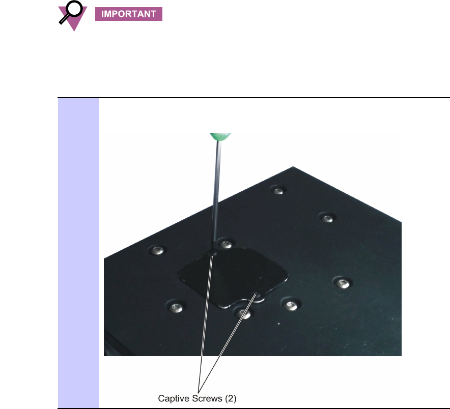
Procedure2-9HowtoRemovetheCryptRCard
1OntheVSMbottomcover,openthetwoTorx8captivescrewsfasteningtheCryptR
carddoor.
2-206802988C54-BJuly2014
VML750—LTEV ehicularSubscriberModem(VSM)InstallationGuideCryptRCardRemovalandInstallation
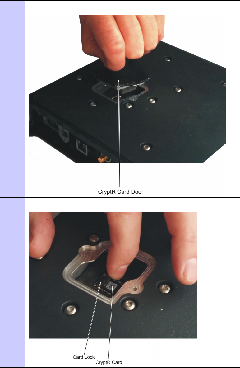
Procedure2-9HowtoRemovetheCryptRCard(Continued)
2Useoneofthecaptivescrewstopullthedoorfromthecover.
3Pullthecardlockbacktoreleaseitandliftitup.
6802988C54-BJuly20142-21
CryptRCardRemovalandInstallationChapter2:VML750Installation
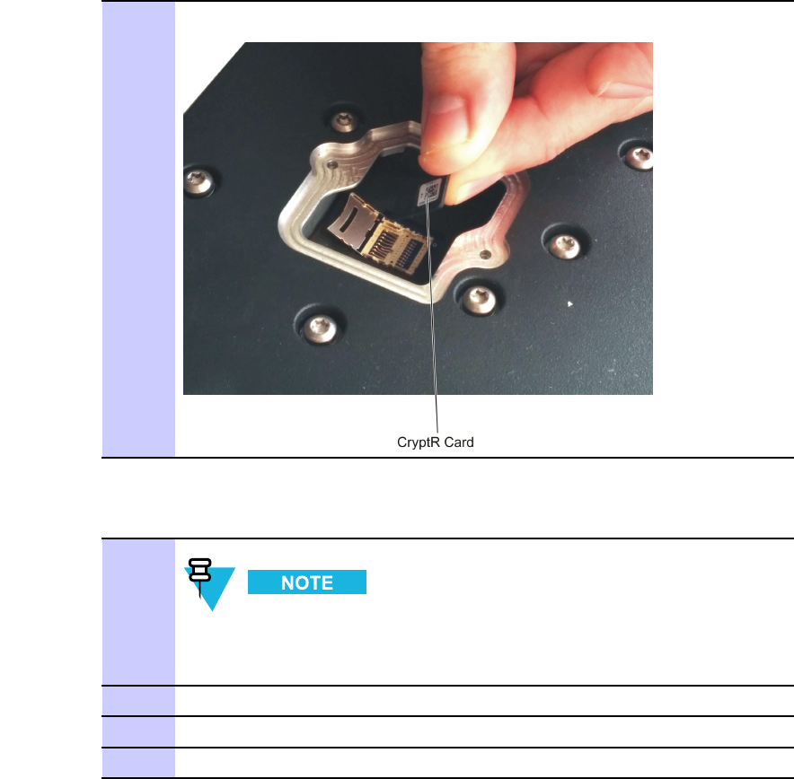
Procedure2-9HowtoRemovetheCryptRCard(Continued)
4RemovethecardfromtheVSM.
Procedure2-10HowtoInstalltheCryptRCard
1
UsethephotosinProcedure2-9tobetterunderstandtherequiredsteps.
InserttheCryptRcardintoitslocationintheVSM.
2Lowerthelockandpushitforwardtolockit.
3InstallthecarddoorontheVSMlowercover.
4ClosetwoTorx8captivescrews.Fastenwithatorqueof12Inch-Lib.
2-226802988C54-BJuly2014
VML750—LTEV ehicularSubscriberModem(VSM)InstallationGuideCapInstallation
CapInstallation
■■■■■■■■■■■■■■■■■■■■■■■■■■■■■■■■■■■■■■■■■■■■
■
■
Procedure2-11HowtoInstallCap(s)onUnusedConnector(s)
1Toprotectanyunusedconnectors(WWAN2,LAN/Ethernet,USB)onthebackof
theVML750,screwcapsprovidedintheinstallationkitontotheseunusedports.
PoweringtheModemUp
■■■■■■■■■■■■■■■■■■■■■■■■■■■■■■■■■■■■■■■■■■■■
■
■
Performthefollowingprocedureafterinstallingthemodem.
Procedure2-12HowtoPoweruptheModem
1Verifythatthevehicle’signitionswitchisinOnposition.
2PressandholdthePowerbuttonontheLEDIndicatorPanelfor2–3seconds.
ReleasethebuttonwhenthePowerLEDturnsgreen(blinkingorsolid).
3IfyourmodemisconnectedtoacomputerusingLAN/Ethernet/USBcable,LAN
LEDturnsgreen.IfnoLAN/Ethernet/USBcableisconnected,LANLEDisoff.
4TheGPSLEDblinksorangewhileyourmodemissearchingforGPSsatellites.
Aftersatelliteshavebeenacquired,theGPSLEDturnsgreen.
Thetimeintervalforacquiringsatellitesduringinitialpowerupmay
takeupto5minutes.
5WiFiLEDistunedoffuntilWiFiconfigurationwasperformed(refertotheVML750
ConfigurationGuide,P/N6802988C55).
DoesnotapplyforB20LTEonlyconfiguration.
6802988C54-BJuly20142-23
PoweringtheModemUpChapter2:VML750Installation
Procedure2-12HowtoPoweruptheModem(Continued)
6AfterconfiguringthemodemtoWiFiAccessPointmode,theWiFiLEDturns
green.Whendataistransferred,theWiFiLEDblinksgreen.
DoesnotapplyforB20LTEonlyconfiguration.
7
IfyourVML750isequippedtosupportLTE,youwillneedtoactivate
itontheassociatedLTEnetwork(yourownprivatePSLTEnetwork
oronthepubliccarriernetwork).Todothis,contactthemanagerof
yournetwork(Motorola,publiccarrier,oryourowninternaltechnical
support)andprovidetheSIMcardidentifiernumber,calledtheIMSI.
ThisidentifiercanbefoundontheplasticcreditcardframefortheSIM.
IfyouareinLTEcoveragearea,thefollowingsequencewilltakeplace,ifaSIM
cardisinsertedandtheSIMdoorisclosed:
1.LTELEDblinksorangewhilethemodemsearchesfortheLTEnetwork.
2.LTELEDblinksgreenwhileregisteringtothenetwork.
3.LTELEDissolidgreenafterregistrationandactivation.
Thetimeintervalforregisteringandactivatingyouraccountmayvary
andcouldtypicallytakeupto2minutes.
IftheSIMdoorisnotclosed,theLTELEDrapidlyblinksred.
IfSIMcardisnotinserted,theLTELEDblinksred.
2-246802988C54-BJuly2014

Chapter
3
TroubleshootingtheVML750
■■■■■■■■■■■■■■■■■■■■■■■■■■■■■■■■■■■■■■■■■■■■
■
■
■
■
Motorolahasmadeeveryefforttoensurethatthisproductisofexcellentquality.However,ifyou
experienceanyproblemswiththeproduct,pleasecontactyourlocalMotorolaservicerepresentative
withproductrelatedinformation.Forcompleteinformationonorderingrequiredpartsandkits,contact
yourlocalcustomerservicerepresentativeandrefertoAppendixB,"Reference".
6802988C54-BJuly20143-1

TroubleshootingChapter3:TroubleshootingtheVML750
Troubleshooting
■■■■■■■■■■■■■■■■■■■■■■■■■■■■■■■■■■■■■■■■■■■■
■
■
Thisparagraphgivesdetailsregardingpossiblemalfunctionsthatmayoccurafterfirst
timeinstallationoftheVML750,theirprobablecauseandtherecommendedcorrective
action.ForcorrectLEDindications,refertoTable3-2.
ContactMotorolaSolutionsSupportCenter(SSC)teamforfurthertroubleshootingassistanceif
necessary.Forcontactinformation,referto"MotorolaSolutionsSupportCenter"onpage-xiv.
Table3-1TroubleshootingtheVML750
MalfunctionProbableCauseCorrectiveAction
Powercableisnotproperly
connected.1.Checkthecableconnections,connectasrequired
andturntheVML750On.
2.V erifythatthePowerLEDisblinkingred
(standbymode).
3.PressthePowerbuttontoturnOn(expectLED
behavioraccordingtoignitionstate).
VML750doesnotturnOn.
Powerbuttonwasnot
properlypressed.1.Applypowertothemodem.
2.V erifythatthePowerLEDisblinkingred.
3.PressthePowerbuttonfor2–3sec.
4.V erifythatthePowerLEDisblinkingorange(in
"ignitionenabled"mode),orblinkinggreenandthen
solidgreen(in"ignitiondisabled"mode).
NoLAN/Ethernet
connection.
LAN/Ethernetcableisnot
connected,or,MicroUSB
cableisnotconnected.
ConnecttheLAN/Ethernetcable(referto
"LAN/EthernetCableInstallation"onpage2-18)or
theMicroUSBcable(referto"MicroUSBCable
Installation"onpage2-18)andverifythattheLAN
LEDisgreen.
NoGPSreception.GPScable(fromMain
antenna)isnotconnected.1.ConnecttheGPScable(referto"AntennaCables
Installation(MainandDiversity)forB20LTEonly
Configuration"onpage2-17or"AntennaCables
Installation(MainandDiversity)forB20LTEonly
Configuration"onpage2-17).
2.V erifythattheGPSLEDisblinkingorangeand
thenchangestosolidgreen.
3-26802988C54-BJuly2014

VML750—LTEV ehicularSubscriberModem(VSM)InstallationGuideTroubleshooting
Table3-1TroubleshootingtheVML750(Continued)
MalfunctionProbableCauseCorrectiveAction
WiFiwasnotconfiguredas
required.
RefertoVML750ConfigurationGuide(6802988C55)
locatedin
https://businessonline.motorolasolutions.com
forWiFiconfiguration.
NoWiFiconnection.
Div/WiFicableisnot
connected.1.ConnecttheDiv/WiFicable(referto"Antenna
CablesInstallation(MainandDiversity)forB20LTE
onlyConfiguration"onpage2-17or"AntennaCables
Installation(MainandDiversity)forB20LTEonly
Configuration"onpage2-17).
2.V erifythattheWiFiLEDisblinking/solidgreen.
6802988C54-BJuly20143-3

TroubleshootingChapter3:TroubleshootingtheVML750
Table3-1TroubleshootingtheVML750(Continued)
MalfunctionProbableCauseCorrectiveAction
Devicehasnotyetbeen
activatedontheLTE
network.
Thefollowingstepsassumesa
subscriptionfortheLTEservicehasbeen
createdbyyournetworkmanageror
serviceprovider.
1.LocateICCID(theidentifierfortheLTESIM
card)orPSN(thedeviceserialnumber)whichwillbe
printedonastickeraffixedtotheVML750casing.
2.Contactthenetworkmanagerortechnicalservice
departmentandreporttheICCIDorthePSNnumber.
3.V erifythatyourdevicehasbeenactivatedon
theLTEnetwork.RefertoProcedure2-12,"Howto
PoweruptheModem,"onpage2-23.
SIMcardisnot
inserted/damaged.1.InsertanewSIMintorelevantSIMslot.Refer
toProcedure2-8,"HowtoInstallaSIMCard,"on
page2-19
2.ClosetheSIMdoor.
3.TurntheVML750On.
4.V erifytheLTELEDisblinkingorange/greenand
thenchangetosolidgreen.
LTEcable(fromMain
antenna)isnotconnected.1.ConnecttheLTEcable(referto"AntennaCables
Installation(MainandDiversity)forB20LTEonly
Configuration"onpage2-17).
2.V erifytheLTELEDisblinkingorange/greenand
thenchangetosolidgreen.
3.Iftheabovedoesnothelp,checktheconnection
betweenthejumperandthethreadcable.
NoLTEconnection.
MissingLTEBand.RefertoVML750ConfigurationGuide(6802988C55)
locatedin
https://businessonline.motorolasolutions.com
fordownloadingthelicencefile.
3-46802988C54-BJuly2014

VML750—LTEV ehicularSubscriberModem(VSM)InstallationGuideLEDIndicatorsFunctions
LEDIndicatorsFunctions
■■■■■■■■■■■■■■■■■■■■■■■■■■■■■■■■■■■■■■■■■■■■
■
■
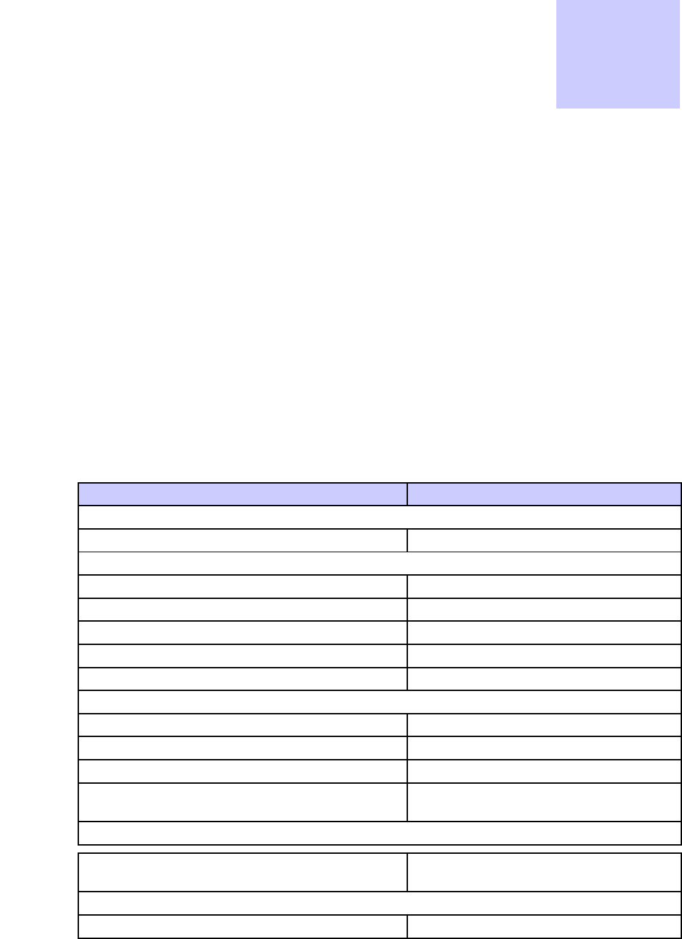
Table3-2describesthefunctionsoftheLEDindicatorsontheVML750frontpanel.
Table3-2LEDIndicatorsFunctions
LEDName:PowerLAN
WWAN1
(Doesnot
applyfor
B20LTEonly
configuration)
WWAN2WiFiGPS
LEDStatus
OFFPoweroffNolinkOffOffOffOff
SolidGreenPoweronLinkisonConnectedConnectedAvailable(for
AP)
Connected(for
client)
Tracking
Blinking
Green
PoweringupTX/RX
Activity
Connecting/
Registering
Connecting/
Registering
TX/RX
Activity(for
AP)
Scanning(for
client)
__
SolidOrange____________
Blinking
Orange
NoIgnition
Theuserturns
thepowerOn
(powerbutton
pressed)but
ignitionisoff
__Searchingfor
signal
Searchingfor
signal
__Searchingfor
signal
SolidRed____Problem/
Overheat
Problem/
Overheat
Problem/
Overheat
Problem
BlinkingRedStandby
Externalpower
isconnectedto
thesystem
__SIMcardisnot
installedinthe
modem
SIMcardisnot
installedinthe
modem
____
Rapid
BlinkingRed
Problem__SIMdoorisopenSIMdoorisopen____
6802988C54-BJuly20143-5
LEDIndicatorsFunctionsChapter3:TroubleshootingtheVML750
Thispageintentionallyleftblank.
3-66802988C54-BJuly2014

Chapter
4
UsingtheVML750
■■■■■■■■■■■■■■■■■■■■■■■■■■■■■■■■■■■■■■■■■■■■
■
■
■
■
General
■■■■■■■■■■■■■■■■■■■■■■■■■■■■■■■■■■■■■■■■■■■■
■
■
AfterinstallingtheVML750inyourvehicleitmustbeconfiguredforproperoperation.Toconfigure
yourmodem,refertoVML750ConfigurationGuideP/N6802988C55.Afterconfiguringthemodem,
itshouldbeturnedonautomaticallyuponyourvehicleignitionandoperateproperly.
IfyoudetectanymalfunctionintheVML750operation,refertoChapter3,"TroubleshootingtheVML750".
6802988C54-BJuly20144-1
GeneralChapter4:UsingtheVML750
Thispageintentionallyleftblank.
4-26802988C54-BJuly2014
Appendix
A
Specifications
Physical
■■■■■■■■■■■■■■■■■■■■■■■■■■■■■■■■■■■■■■■■■■■■
■
■
Dimensions(Modem)8.07”x7.87”x1.71”(20.5cmx20cmx4.35cm±1mm)
Weight(Modem)6Pounds(2.5Kg)
CommunicationPorts
AmphenolLAN–Ethernet10/100–RJ45
USB2.0highspeed–MicroAB
RFPorts
WWAN1MAIN1SMAconnector(Female)(doesnotapplyforB20LTE
onlyconfiguration)
WWAN1Diversity+WiFiSMAconnector(Female)(doesnotapplyforB20LTE
onlyconfiguration)
WWAN2MainRx/TxSMAconnector(Female)
WWAN2Diversity(Diversity+WiFiforB20
LTEonly)
SMAconnector(Female)
GPSSMAconnector(Female)
6802988C54-BJuly2014A-1
PowerPortAppendixA:Specifications
PowerPort
Power9-pinD-TYPE
LEDs
RefertoTable3-2.
OperatingTemperature
Ambienttemperature-30°Cto+60°C
Power
InputV oltage11to33VDC
PowerConsumption:
ModemStandby<0.3ARMS
ModemTransmit<1ARMS
RFCharacteristics
Frequency:
LTE4GBC14Tx788–798MHz
4GBC14Rx758–769MHz
4GBC13Tx777–787MHz
4GBC13Rx746–756MHz
EVDO3GBC0Tx824–849MHz
3GBC0Rx869–894MHz
3GBC1Tx1850–1910MHz
3GBC1Rx1930–1990MHz
WiFi2401-2472MHz
Bandwidth:
LTE5MHz
10MHz
WiFi20MHz(802.11b/g/n)
A-26802988C54-BJuly2014

VML750—LTEV ehicularSubscriberModem(VSM)InstallationGuideRFCharacteristics
Outputtransmitpower:
LTE23dBm
EVDO23dBm
WiFi15dBm
Receiversensitivity:
LTE10MHz-94dBm,typ-96dBm
5MHz-97dBm,typ-99dBm
WiFi(802.11g)-87dBm
FrequencyStability:
LTE±2.5ppm
WiFi±20ppm
6802988C54-BJuly2014A-3
Thispageintentionallyleftblank.
A-46802988C54-BJuly2014
Appendix
B
Reference
ReplacementParts
■■■■■■■■■■■■■■■■■■■■■■■■■■■■■■■■■■■■■■■■■■■■
■
■
Replacedamagedpartswithidenticalreplacementparts.
Forcompleteinformationonorderingrequiredpartsandkits,pleasecontactyour
localMotorolaservicerepresentative.
ReplacementPartsList
Kit/PartNumberDescription
Antennas
Referto"ApprovedAntennasList"onpageB-2
Bracket,Screws&Washers
0312002B14MountingScrew,BrackettoCar,8
03013013001MountingScrew,VSMtoBracket,8
0487779V56FlatWasher,VSMtoBracket,8
0487623U12SpringWasher,VSMtoBracket,8
07013065001Bracket,2
Cables
FKN8570LAN/EthernetCable(177”/450cm)
FKN8730MicroUSBcable
FKN8663DCPower&IgnitionCable(177”/450cm)
FKN8671DCPower&IgnitionCable+GPIO(177”/450
cm)
SIMcard
TBDSIMCardKit(thexstandsforthecustomer
number)
CryptRcard
TBDCryptRMicroSDcard
6802988C54-BJuly2014B-1
KitReplacementPartsListAppendixB:Reference
KitReplacementPartsList
Kit/PartNumberDescription
FLN1310VML750,BC20LTEVSMModem
FLN1057VML750,VzWLTEVSMModem
ApprovedAntennasList
Kit/Part
NumberKitDescription
AN000036A01VML750baseantennawithacap
FTN0073
(85013022001)WidebandFix-MountedV ehicularAntenna(12ftcable)
FTN7686
(85013016001)LTEWhipAntenna
FTN6070
(85013022001)WidebandFix-MountedV ehicularAntenna(17ftcable)
AntennasCablesReplacements
Kit/Part
NumberKitDescription
CB000133A01SMA-FtoSMA-M12ftRG174cabletype
CB000133A02SMA-FtoSMA-M17ftRG174cabletype
30013096001NMOAntennaMount
30013072001SMA-FtoSMA-M12ftLMR200cabletype
30013093001SMA-FtoSMA-M17ftLMR240cabletype
B-26802988C54-BJuly2014

Appendix
C
LTE&LMRAntennasMounting
Recommendations
ThisappendixprovidesproceduresfordeterminingthemountinglocationsforaPublicSafetyNarrow
Band(PSNB)LMR700/800MHzantennaandBroadBand(BB)LTE700MHzantennas.
Thefollowingproceduresaregiven:
•PolicepatrolvehiclewithaPSNBantennaandastandardBBantenna.
•BuswithaPSNBantennaandalowprofileBBantenna
PolicePatrolVehicleAntennasLocationConsiderations
—Overview
■■■■■■■■■■■■■■■■■■■■■■■■■■■■■■■■■■■■■■■■■■■■
■
■
Theantennasmountinglocationisselectedindividuallyforeveryvehiclebeforestartingtheactual
installationprocess.Thefollowinglistgivesgeneralrecommendationsfordeterminingthemounting
locationofPSNBandBBantennasbasedonseveralkeyconsiderations:
•Keepaminimumdistanceof7.87”(20cm)betweentheLTE[BB]antennas;including
WiFitoanyotherantennaandanypotentialbystander(forbystandersafely).
•FollowtheguidelinesintheinstallationandsafetymanualsoftheLMR
[PSNB]radioswithregardstomountinglocationsandoperationofradiointhe
presenceofbystanders(forbystandersafety).
•Keepaminimumspatialseparationof78”(198cm)betweenthePSNBandBBLTEantennas
thisseparationprovidesaminimumof35dBisolationtoreduceinterferences.
•Keepaminimumspatialseparationof36”(91.4cm)betweenthetwoBBLTE(mainand
diversity)antennasforpotentialinterferencereductionandforoptimalMultipleInputMultiple
Output(MIMO)andMaximumRatiodiversityCombining(MRC)performance.
6802988C54-BJuly2014C-1
PlanningAntennaMountingLocationonaPolicePatrolVehicleAppendixC:LTE&LMRAntennasMountingRecommendations
PlanningAntennaMountingLocationonaPolicePatrol
Vehicle
■■■■■■■■■■■■■■■■■■■■■■■■■■■■■■■■■■■■■■■■■■■■
■
■
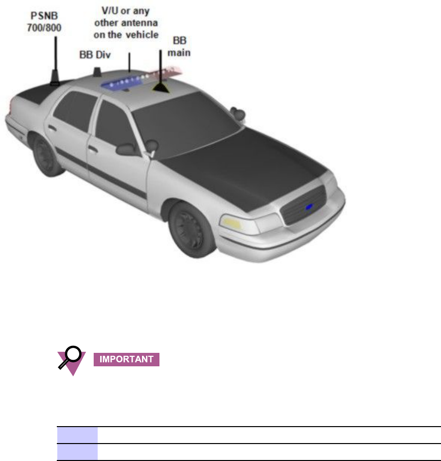
FigureC-1showsabasicsuggestionforantennaslocation.ProcedureC-1describestheplanning.
FigureC-1PolicePatrolVehicle—AntennasLocationSuggestion
Legend:
•BB—BroadBandL TEAntennas
•PSNB—PublicSafetyNarrowBand700/800Antenna
•V/U—ExistingVHF/UHFAntenna
Antennasmustbeinstalledonaflatmetalsurface(minimumsize24”(61cm)x24”(61cm)).
ProcedureC-1PlanningAntennasLocationonaPolicePatrolVehicle
1Observetheexistingantennas.
2Drawanimaginary36”(91.4cm)radiuscirclesaroundtheexistingantennas.
C-26802988C54-BJuly2014

VML750—LTEV ehicularSubscriberModem(VSM)InstallationGuidePlanningAntennaMountingLocationonaPolicePatrolVehicle
ProcedureC-1PlanningAntennasLocationonaPolicePatrolVehicle(Continued)
3Drawimaginarylines7.8”(20cm)frombothsidesofthevehicle'sroofandtrunk
cover.
4Planmountingtheantennasonareasdeterminedbystep2and3i.e.notcloserthan
36”(91.4cm)toanyexistingantennaandatleast7.8”(20cm)fromthevehicle
sides.
5Plantheantennasmountinglocations,takingintoaccounttheavailablecoaxial
cableslength.
6Ifpossible,planmountingthePSNBantennaonthevehicle'strunkcover.
7DefinetheDiversityBBantennalocationonthevehicle'sroofwithaminimum
directdistanceof78”(198cm)fromthePSNBantenna.IfaPSNBantennaisnot
required,planmountingtheDiversity/WiFiantennaonthevehicle’strunkcover.
8DefinetheMainBBantennalocationonthevehicle'sroofwithaminimumdistance
of36”(91.4cm)totheDiversityBBantennaandof78”(198cm)tothePSNB
antenna.Itisrecommendedtoinstallthemainantennaonthecenterlineatthe
frontsideofthevehicle'sroof.
9SomevehiclesmayalreadyhaveaPSNBantennamounted.Forthesevehicles,itis
recommendedtoreinstallthePSNBantennaonthevehicle'strunkcover.
6802988C54-BJuly2014C-3