Motorola Solutions 92FT7102 Ultra Portable LTE Infrastructure User Manual LXN500 Installation Manual
Motorola Solutions, Inc. Ultra Portable LTE Infrastructure LXN500 Installation Manual
UserManual.wiki
>
Motorola Solutions
>
92FT7102 User Manual
>
User manual
Contents
1.
User manual
2.
Safety booklet
User manual
Navigation menu
Upload a User Manual
Namespaces
Wiki Guide
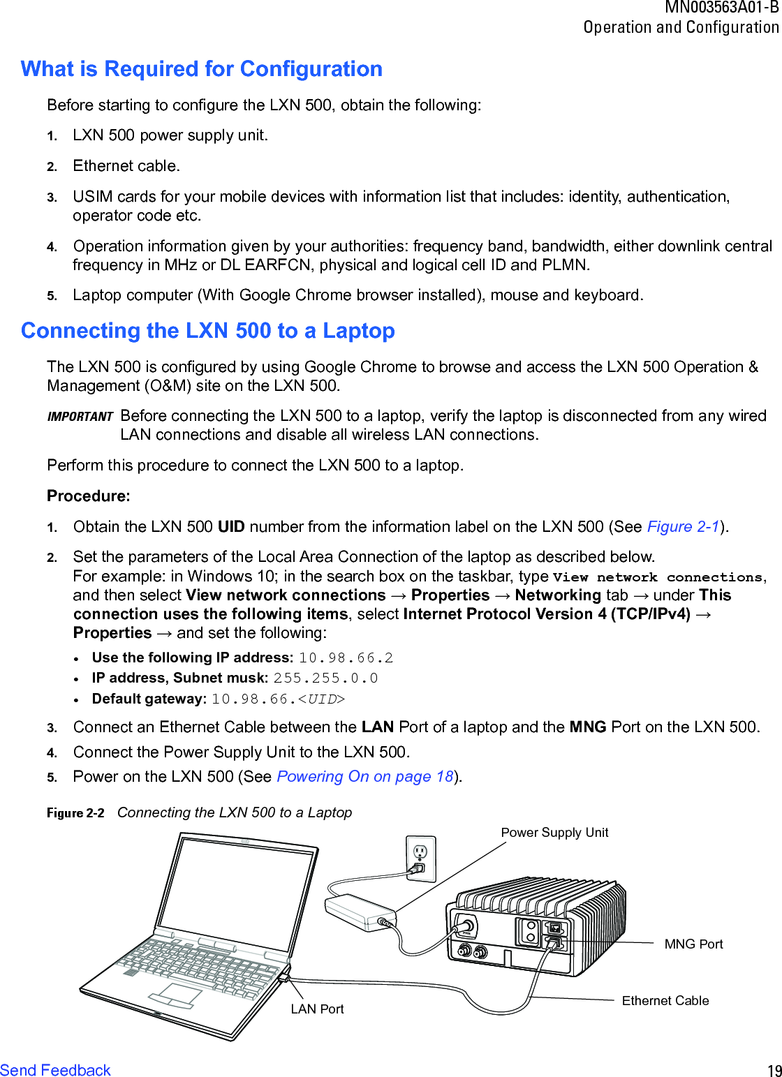
HTML
PDF
Info
Views
User Manual
Discussion / Help
Navigation
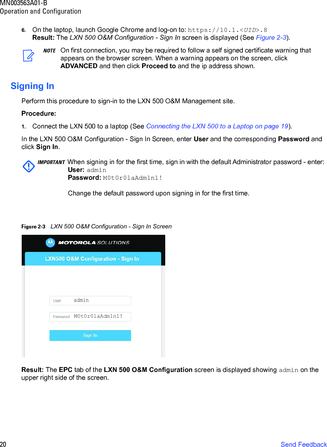
![MN003563A01-BOperation and Configuration36 Send Feedback3. In the iperf command field, edit the iperf default command line to customize the communicationtests using the following command line arguments:Command Line Structureiperf [-s|-c <Host>] [-u] [-p <Port>] [-B <Interface>] [-c] [-b <Bandw>[kKmM]] [-l <Length>] [-t <Time>] [-d] [-r] [-L <Port>] [-h]Table 2-4 iperf Command Line Options Command Line Option DescriptionClient/Server-u, --udp Uses UDP instead of TCP.-p, --port <Port> Connects with or expects data packets on this port (default: 5001).-B, --bind <Interface> Permits the connection only via the specified interface (IP address or interface name).Server Specific-s, --server Starts iPerf in server mode and waits for an iPerf client to contact it.Client specific-c, --client <Host> Starts iPerf in client mode and connects with the iPerf server <Host> (IP address or DNS name).-b, --bandwidth<Bandw>{kKmM}Limit the [down]/up-stream bandwidth when analyzing a UDP connection. This Is specified as kilobytes (kK) or megabytes (mM) per second (default: 1 Mbps).-l, --len <Length> Sets the length of the UDP data packets.-t, --time <Time> Sets the duration of the connection in seconds (default: 10 seconds).-d, --dualtest The test is bidirectional: the iPerf server and client send and receive at the same time.-r, --tradeoff The test is sequential: the iPerf server and client send and receive one after the other.-L, --listenport <Port> Specifies the port where the device in bidirectional mode expects to receive data packets from the remote iPerf server (default: 5001).Miscellaneous-h, --help Outputs the help text.Using ping Ping Command Line Structure:ping [-t] [-a] [-n count] [-l size] [-f] [-i TTL] [-v TOS] [-r count] [-s count] [[-j host-list] | [-k host-list]] [-w timeout] [-R] [-S srcaddr] [-4] [-6] target_name](https://usermanual.wiki/Motorola-Solutions/92FT7102.User-manual/User-Guide-3634537-Page-36.png)
![43MN003563A01-BOperation and ConfigurationSend FeedbackAbout LXN 500The About screen enables system administrators and technicians to identify the vendors and version of software components within the LXN 500.Perform this procedure to generate view and manage an event log.1. Sign in to the LXN 500 O&M Configuration site (See Signing In on page 20).2. Click the About tab.Figure 2-22 About LXN 500 ScreenConfiguring the DragonForce ServerPerform this procedure to Configure the DragonForce Server:1. Sign in to the LXN 500 O&M Configuration site (See Signing In on page 20).2. Click the Help tab.3. Click Links → DF.4. Enter User Name: admin and Password: [DF]Motorola15. Click Log In.Result: The DragonForce Log In screen is displayed.IMPORTANT To avoid a security breach, it is recommended to change the password upon signing in for the first time. For changing the password, refer to DragonForce documentation.](https://usermanual.wiki/Motorola-Solutions/92FT7102.User-manual/User-Guide-3634537-Page-43.png)