Motorola Solutions 92FT7102 Ultra Portable LTE Infrastructure User Manual LXN500 Installation Manual
Motorola Solutions, Inc. Ultra Portable LTE Infrastructure LXN500 Installation Manual
Contents
- 1. User manual
- 2. Safety booklet
User manual

a
a
LXN 500
Installation
Configuration and
Operation Guide
OCTOBER 2017
© 2017 Motorola Solutions, Inc. All rights reserved
MN003563A01-B
System Release 1.0

MN003563A01-B
Copyrights
2Send Feedback
Copyrights
The Motorola products described in this document may include copyrighted Motorola computer
programs. Laws in the United States and other countries preserve for Motorola certain exclusive rights
for copyrighted computer programs. Accordingly, any copyrighted Motorola computer programs
contained in the Motorola products described in this document may not be copied or reproduced in any
manner without the express written permission of Motorola.
© 2017 Motorola Solutions, Inc. All Rights Reserved
No part of this document may be reproduced, transmitted, stored in a retrieval system, or translated into
any language or computer language, in any form or by any means, without the prior written permission of
Motorola Solutions, Inc.
Furthermore, the purchase of Motorola products shall not be deemed to grant either directly or by
implication, estoppel or otherwise, any license under the copyrights, patents or patent applications of
Motorola, except for the normal non-exclusive, royalty-free license to use that arises by operation of law
in the sale of a product.
Disclaimer
Please note that certain features, facilities, and capabilities described in this document may not be
applicable to or licensed for use on a particular system, or may be dependent upon the characteristics of
a particular mobile subscriber unit or configuration of certain parameters. Please refer to your Motorola
contact for further information.
Trademarks
MOTOROLA, MOTO, MOTOROLA SOLUTIONS, and the Stylized M Logo are trademarks or registered
trademarks of Motorola Trademark Holdings, LLC and are used under license. All other trademarks are
the property of their respective owners.
The European Union's WEEE directive requires that products sold into EU countries must have the
crossed out trash bin label on the product (or the package in some cases).
As defined by the WEEE directive, this cross-out trash bin label means that customers and end-users in
EU countries should not dispose of electronic and electrical equipment or accessories in household
waste.
Customers or end-users in EU countries should contact their local equipment supplier representative or
service center for information about the waste collection system in their country.

3
MN003563A01-B
Contact Us
Send Feedback
Contact Us
Motorola Solution Support Center
The Solution Support Center (SSC) is the primary Motorola Solutions support contact. Call:
•
Before any software reload.
•
To confirm troubleshooting results and analysis before removing and replacing a Field Replaceable
Unit (FRU) and Field Replaceable Entity (FRE) to repair the system.
North America Parts Organization
For assistance in ordering replacement parts or identifying a part number, contact the Motorola Parts
organization. Your first response when troubleshooting your system is to call the Motorola SSC.
Comments
Send questions and comments regarding user documentation to
documentation@motorolasolutions.com.
Provide the following information when reporting a documentation error:
•
The document title and part number
•
The page number with the error
•
A description of the error
We welcome your feedback on this and other Motorola manuals. To take a short, confidential survey on
Motorola Customer Documentation, go to docsurvey.motorolasolutions.com or scan the following QR
code with your mobile device to access the survey.
Latest Manual Versions
You can verify the latest version of this manual at https://businessonline.motorolasolutions.com.
For... Phone
United States Calls 800-221-7144
International Calls 302-444-9800
For... Phone
Phone Orders 800-422-4210 (US and Canada Orders)
For help identifying an item or part number, select choice 3 from the menu.
International
Calls
302-444-9842 (International Orders)
Includes help for identifying an item or part number and for translation as
needed.
Fax Orders 800-622-6210 (US and Canada Orders)

MN003563A01-B
Document History
4Send Feedback
Document History
FCC Information
This device complies with Part 15 of the FCC rules:
Operation is subjected of the following two conditions:
(1) This device may not cause harmful interference, and (2) This device must accept any interference
received, including interference that may cause undesired operation.
FCC ID: AZ492FT7102
Version Description Date
MN003563A01-A Release release of the LXN 500 07/2017
MN003563A01-A Update to LXN 500 O&M configuration section 10/2017
5
MN003563A01-B
Contents
Send Feedback
Contents
Copyrights .................................................................................................................................. 2
Contact Us .................................................................................................................................. 3
Document History ...................................................................................................................... 4
FCC Information ......................................................................................................................... 4
About LXN 500 ........................................................................................................................... 9
What is Covered in This Manual ...................................................................................................... 9
Helpful Background Information ....................................................................................................... 9
Related Information .......................................................................................................................... 9
Overview ..................................................................................................................................... 11
LXN 500 Front Panel Features ........................................................................................................ 12
LXN 500 Back Panel Features ......................................................................................................... 16
Operation and Configuration .................................................................................................... 17
Getting Started ................................................................................................................................. 17
Obtaining the Unit Identification (UID) Number ...................................................................... 17
Powering On .................................................................................................................................... 18
Powering Off .................................................................................................................................... 18
Starting Shutdown Sequence ................................................................................................. 18
Forcing Power Off ................................................................................................................... 18
What is Required for Configuration .................................................................................................. 19
Connecting the LXN 500 to a Laptop ............................................................................................... 19
Signing In ......................................................................................................................................... 20
Viewing System Notifications ........................................................................................................... 21
Signing Out ...................................................................................................................................... 21
Account Management ...................................................................................................................... 22
User Roles and Management Permissions ............................................................................ 22
Passwords .............................................................................................................................. 23
Adding a Single Subscriber (UEs) .................................................................................................... 24
Deactivating/Activating Subscriber ................................................................................................... 25
Importing Subscribers From .csv File ............................................................................................... 26
Deleting Subscriber .......................................................................................................................... 27
Deleting All Subscribers ................................................................................................................... 27
UE Activity ........................................................................................................................................ 28
Statistics ........................................................................................................................................... 29
Setting the eNodeB .......................................................................................................................... 30
Setting the System ........................................................................................................................... 31
PLMN Settings ........................................................................................................................ 31
Backing-up and Restoring ...................................................................................................... 32
Performing Diagnostics ........................................................................................................... 33
About LXN 500 ................................................................................................................................. 43
Configuring the DragonForce Server ............................................................................................... 43
Configuring the WAVE 5000 Server ................................................................................................. 44
MN003563A01-B
Contents
6Send Feedback
Provisioning the Mobile Device (UE) ................................................................................................ 45
Vehicle Installation .................................................................................................................... 47
Unpacking ........................................................................................................................................ 47
Configuration Options of Antenna Installation .................................................................................. 48
Dome Antenna Configuration ................................................................................................. 48
Dual Diversity Antenna Configuration ..................................................................................... 49
Preparing to Install the LXN 500 ...................................................................................................... 50
Tools ....................................................................................................................................... 50
Materials ................................................................................................................................. 50
Planning ........................................................................................................................................... 50
Ventilation ............................................................................................................................... 51
Electrical Guidelines ............................................................................................................... 52
Ground Polarity ....................................................................................................................... 52
Installing the Power Cable ...................................................................................................... 53
Cable Routing ......................................................................................................................... 54
Installing the Optional Power Protection and Back-up Unit .............................................................. 54
Installing the LXN 500 ...................................................................................................................... 55
Installing Antennas ........................................................................................................................... 56
Mounting Guide lines .............................................................................................................. 57
Troubleshooting and Maintenance .......................................................................................... 59
Troubleshooting ............................................................................................................................... 60
Software Update .............................................................................................................................. 62
Resetting the LXN 500 ..................................................................................................................... 62
Soft Reseting using the Power Button .................................................................................... 62
Soft Resetting via O&M .......................................................................................................... 62
Hard Resetting ........................................................................................................................ 62
Resetting the eNodeB ...................................................................................................................... 63
Technical Specifications ........................................................................................................... 65
7
MN003563A01-B
List of Figures
Send Feedback
List of Figures
The LXN 500 .............................................................................................................................................. 11
Front Panel Features ................................................................................................................................ 12
LXN 500 Back Panel Features .................................................................................................................. 16
LXN 500 Information Label ........................................................................................................................ 17
Connecting the LXN 500 to a Laptop ......................................................................................................... 19
LXN 500 O&M Configuration - Sign In Screen .......................................................................................... 20
EPC Tab .................................................................................................................................................... 21
Add USIM Fields ........................................................................................................................................ 24
USIM is Displayed in a Table on the EPC Tab Screen .............................................................................. 25
An Example of .csv file with list of USIMs .................................................................................................. 26
Importing Subscribers from .csv File ........................................................................................................ 27
UE Activity Screen ..................................................................................................................................... 28
Statistics Screen ........................................................................................................................................ 29
eNodeB Screen ......................................................................................................................................... 30
PLMN Settings Screen .............................................................................................................................. 32
Backing-up and Restoring Servers and Applications ................................................................................. 33
Communication Diagnostics ...................................................................................................................... 34
Communication Test Screen ..................................................................................................................... 35
Battery Diagnostics .................................................................................................................................... 38
Ports Test Screen ..................................................................................................................................... 39
System Health Screen .............................................................................................................................. 40
LEDs Test .................................................................................................................................................. 41
System Status ............................................................................................................................................ 41
System Logging Screen ............................................................................................................................ 42
About LXN 500 Screen .............................................................................................................................. 43
DragonForce Log In Screen ...................................................................................................................... 44
WAVE 5000 Server Log In Screen ............................................................................................................ 44
Dome Antenna ........................................................................................................................................... 48
Dual Diversity Antenna .............................................................................................................................. 49
Recommended Clear Ventilation Area Around the LXN 500 ..................................................................... 52
Connecting the LXN 500 to Power and Ground ........................................................................................ 53
Cable Routing into Engine Compartment .................................................................................................. 53
Installing the Optional Power Protection and Back-up Unit ....................................................................... 55
LXN 500 Installed Inside a Trunk of a Vehicle ........................................................................................... 56
MN003563A01-B
List of Tables
8Send Feedback
List of Tables
Front Panel Features ................................................................................................................................ 12
Features of LXN 500 Front Panel .............................................................................................................. 12
LXN 500 Rear Panel Connectors .............................................................................................................. 16
Back Panel Features ................................................................................................................................ 16
Management Permissions Assigned to Each User Role in the LXN 500 .................................................. 22
Default Password Assigned to Each User Role ......................................................................................... 23
eNodeB Band Configuration ...................................................................................................................... 30
iperf Command Line Options ..................................................................................................................... 36
Troubleshooting ......................................................................................................................................... 60

9
MN003563A01-B
About LXN 500
Send Feedback
About LXN 500
This manual provides functional overview and procedures for the LXN 500.
What is Covered in This Manual
This manual contains the following chapters:
• Overview on page 1-11 provides overview of the LXN 500 system and its features.
• Vehicle Installation on page 3-47 contains procedures for installing LXN 500 hardware components.
• Operation and Configuration on page 2-17 contains procedures for powering up and configuring the
LXN 500.
• Troubleshooting and Maintenance on page 4-59 provides an overview of LXN 500 management and
solutions to common problems.
Helpful Background Information
Motorola Solutions offers various courses designed to assist in learning about the system. For
information, go to http://www.motorolasolutions.com/training to view the current course offerings and
technology paths.
Related Information
Unless otherwise specified, the Motorola documents listed here are available from Motorola Online at
http://businessonline.motorolasolutions.com. If you are new to Motorola Online, follow the on-screen
instructions to sign up for an account. To access Public Safety LTE infrastructure manuals, select
Resource Center → Product Information → Manuals → Private Broadband Solutions and select the
appropriate release. The Resource Center also provides a Search function.
Customers outside of the Americas can contact Motorola Solutions for the documentation listed here.
Refer to the following documents for information about this product:
Related Documentation
Related Information Purpose
Administration Guide WAVE 5000 R5.12 Explains how to operate, administer, and maintain the WAVE 5000
Push-To-Talk (PTT) system available from Motorola Solutions.
DragonForce Maps Server
Documentation
https://www.drakontas.com/?p=academy
Explains how to configure DragonForce server for user tracking on
maps (street map view & satellite views) - see where you and your
team members are located.
Public Safety LTE Glossary Lists abbreviations for Public Safety LTE terms.
Product Safety Guide (multilingual) -
Motorola Solutions P/N 6866537D37
RF Energy Exposure and Product Safety Guide for Mobile Two-Way
Radios installed in Vehicles or as Fixed Site Control Stations
LXN 500 Quick Start Guide - Motorola
Solutions P/N MN003599A01
First time use of the LXN 500.
11
MN003563A01-B
Overview
Send Feedback
Overview
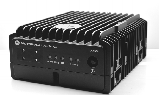
The LXN 500 is an ultra deployable LTE system designed for on-demand coverage and public safety
applications. The solution consists of a single standalone portable unit that operates from within a
vehicle.
Figure 1-1
The LXN 500
The LXN 500 enables a rapid deployment of a tactical communication network, within a limited
geographical area and used by up to 100 subscribers.
The LXN 500 may include the WAVE™ 5000 Mobile Communicator and DragonForce - Drakontas
mobile collaboration applications.
The WAVE 5000 Mobile Communicator enable the mobile devices connected to LXN 500 to a
multi-channel Push-To-Talk (PTT) handsets for fully secure, real-time PTT voice communication. WAVE
5000 also connects the LXN 500 subscribers to Land Mobile Radio (LMR) users to provide unified voice,
text messaging and presence in a single and easy-to-use application.
DragonForce is a mobile collaboration application that allows teams to create and share information
more rapidly, accurately and effectively. The application includes secure, real-time, team-based
information such as: user tracking on maps (street map view & satellite views), team members location,
images or maps, whiteboards, text messaging to individuals and teams, customizable shared forms. You
can also capture data in the field and share with other users, distribute documents, images, and other
files.
LXN 500 is a self-managed mobile network based on standard 4G LTE cellular communication on
bands: 14, 20, 28B and does not require any human intervention during operation.
MN003563A01-B
Overview
12 Send Feedback
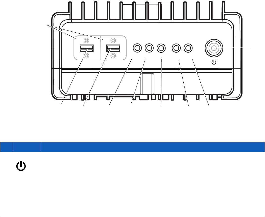
LXN 500 Front Panel Features
Figure 1-2 shows and Table 1-1 describes the features of the LXN 500 front panel.
Figure 1-2
Front Panel Features
Table 1-1
Front Panel Features
Ab
SOLUTIONS
LXN 500
RADIO
1
23456
78
CORE APP 1-BAT-2
1 2
Protective Covers
Close covers when
not in use.
Table 1-2
Features of LXN 500 Front Panel
Item Description
1
Power button.
To power on; hold pressed for four seconds.
To start shutdown sequence; hold pressed for four seconds.
To force power off; hold pressed for more than 15 seconds.
When the LXN 500 is powered by batteries in backpack configuration (Future option of the
LXN 500), one second press of the Power button switches between active and standby
backpack battery.

13
MN003563A01-B
Overview
Send Feedback
2
BAT2
Status LED of backpack battery 2 (Future option of the LXN 500).
NOTE To switch between active and standby battery, press the Power button for one second
and release.
•
LED OFF - No battery or battery is disconnected
•
GREEN - Battery is active and its capacity is more than 50%
•
BLINKING GREEN - Battery is in Standby mode and its capacity is more than 50%
•
ORANGE - Battery is active and its capacity is 10% to 50%
•
BLINK ORANGE - Battery is in Standby mode and its capacity is 10% to 50%
•
RED - Battery s active and its capacity is less than 10%
•
BLINKING RED - Battery is in Standby mode and its capacity is less than 10%
3
BAT1
Status LED of backpack battery 1(Future option of the LXN 500).
NOTE To switch between active and standby battery, press the Power button for one second
and release.
•
LED OFF - No battery or battery is disconnected
•
GREEN - Battery is active and its capacity is more than 50%
•
BLINKING GREEN - Battery is in Standby and its capacity is more than 50%
•
ORANGE - Battery is active and its capacity is 10% to 50%
•
BLINK ORANGE - Battery is in Standby mode and its capacity is 10% to 50%
•
RED - Battery is active and its capacity is less than 10%
•
BLINKING RED - Battery is in Standby mode and its capacity is less than 10%
4
APP
APP is a status LED used to diagnose and troubleshoot the LXN 500. Refer to
Troubleshooting and Maintenance whenever the LED shows orange or red color.
The APP (Application Server) stores the applications used by the LXN 500. The optional
applications provided with the LXN 500 are the WAVE 5000 that enables full interoperability
between LTE and land mobile radio systems and the DragonForce software.
•
LED OFF - OFF
•
GREEN - All applications are running
•
BLINKING GREEN - Applications startup in progress
•
ORANGE - Not all applications are running. At least one application is down and one is
running
•
BLINKING ORANGE - Applications shutdown in progress
•
RED - Failure: All applications are down
•
BLINKING RED - Fatal Error: Cannot connect to application server
Table 1-2
Features of LXN 500 Front Panel (Continued)
Item Description

MN003563A01-B
Overview
14 Send Feedback
5
CORE
CORE is a status LED used to diagnose the CORE (Evolved Packet Core - EPC).
The CORE is a framework for providing converged of voice and data including HTTP web
server on a 4G LTE network. Refer to Troubleshooting and Maintenance whenever the LED
shows orange or red color.
•
LED OFF - OFF
•
GREEN - All EPC processes are running and S1 (Communication between eNodeB
and EPC) is up
•
BLINKING GREEN - EPC startup in progress
•
ORANGE - One or more EPC processes are down and one or more are active or S1 is
down
•
BLINKING ORANGE - EPC shutdown in progress
•
RED - Failure. All EPC processes are down
•
BLINKING RED - Fatal error. Cannot connect to EPC
6
RADIO
RADIO is a status LED used to diagnose and troubleshoot the eNodeB transceiver that
enables the LXN 500 to communicate directly with end-user devices.
Refer to Troubleshooting and Maintenance whenever the LED shows orange or red color.
LED OFF - OFF
GREEN - L1 and L2 and L3 are running
BLINKING GREEN - Startup eNodeB startup in progress
ORANGE - One or more eNodeB processes are down and one or more are active
BLINKING ORANGE - eNodeB Shutdown in progress
RED - Failure - L1, L2, and L3 are down
BLINKING RED - Fatal Error - No connection to eNodeB board
7
1
USB 2.0 port for connecting peripheral devices such flash-disks to the LXN 500. The USB
port is covered by a protective cover.
IMPORTANT
- To enable a successful boot-up, remove all USB devices connected to the
LXN 500 before powering on.
-The LXN 500 supports only FAT32 file system disks.
NOTE
To ensure proper communication, use USB extension cable shorter than 9.8 feet
(3 meters).
Table 1-2
Features of LXN 500 Front Panel (Continued)
Item Description

15
MN003563A01-B
Overview
Send Feedback
8
2
USB 2.0 port for connecting peripheral devices such flash-disks to the LXN 500. The USB
port is covered by a protective cover.
IMPORTANT
- To enable a successful boot-up, remove all USB devices connected to the
LXN 500 before powering on.
-The LXN 500 supports only FAT32 file system disks.
NOTE
To ensure proper communication, use USB extension cable shorter than 9.8 feet
(3 meters).
Table 1-2
Features of LXN 500 Front Panel (Continued)
Item Description
MN003563A01-B
Overview
16 Send Feedback
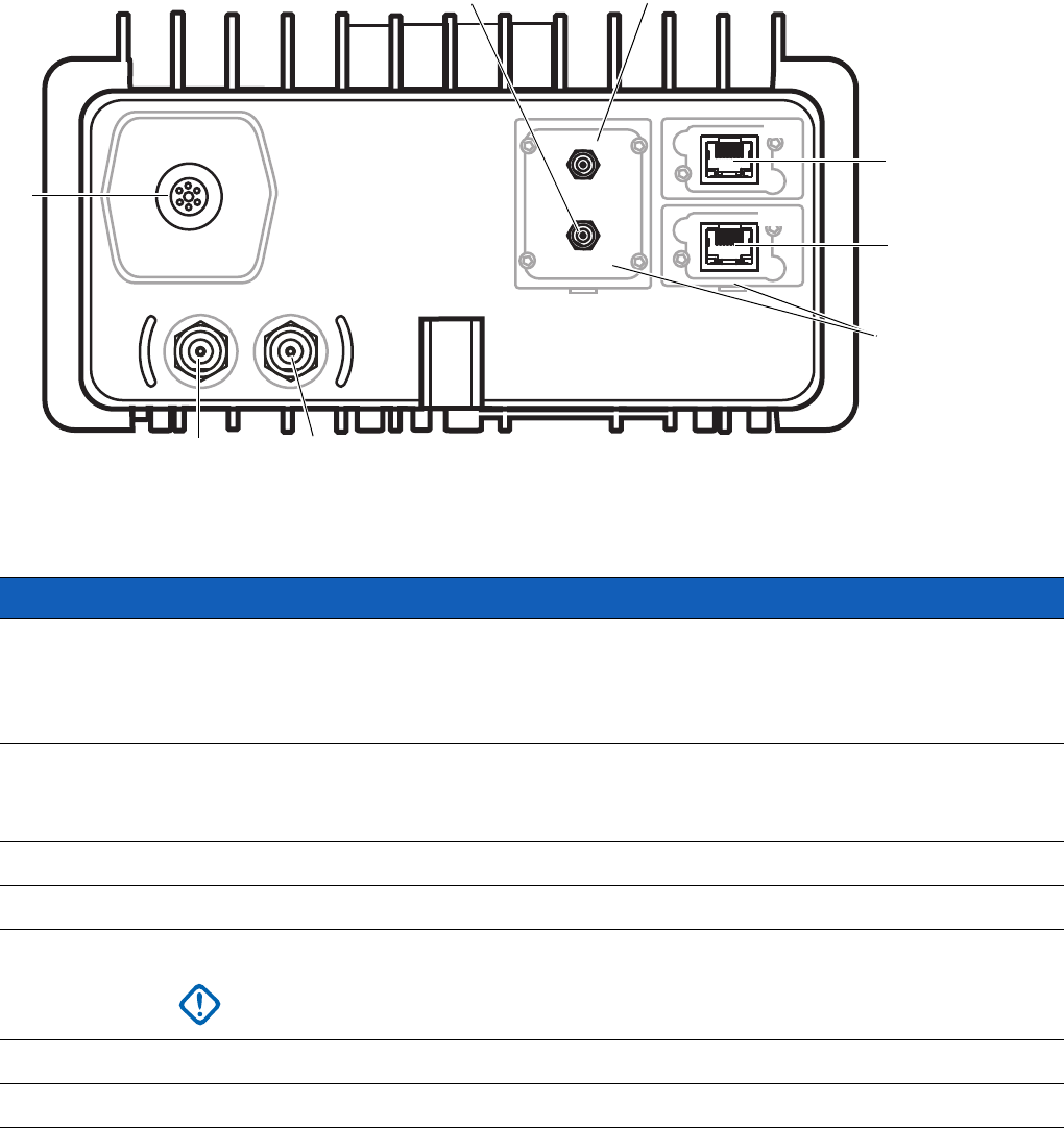
LXN 500 Back Panel Features
Figure 1-3 shows and Table 1-3 describes the features of the back panel of the LXN 500.
Figure 1-3
LXN 500 Back Panel Features
Table 1-3
LXN 500 Rear Panel Connectors
1
2
4
5
67
PWR
LTE1 LTE2
WIFI
GPS
NET
3
MNG
Protective Covers
Close covers when not in use.
Table 1-4
Back Panel Features
Connector Description
1NET
Network (NET) 1 GBit/s LAN port.
This port is used for connecting the LXN 500 to a Local Area Network (LAN) infrastructure
or an external application server. When maintenance is required, this port enables access
to the servers and eNodeB of the LXN 500.
2MNG
Management (MNG) 1 GBit/s LAN port.
This port is used for connecting an external laptop for configuration, management and
maintenance tasks.
3LTE2
LTE antenna connector.
4LTE1
LTE antenna connector.
5 PWR IN
9 to 33 VDC input power from car or backpack batteries
(Future option of the LXN 500)
.
IMPORTANT
Do not remove the power cable before shutting down the LXN 500.
Verify that the all LEDs on the front panel are off.
2GPS
GPS antenna connector.
3WiFi
Wireless LAN antenna connector.
17
MN003563A01-B
Operation and Configuration
Send Feedback
Operation and Configuration
This chapter describes the initial operation and configuration of the LXN 500 system.
Getting Started
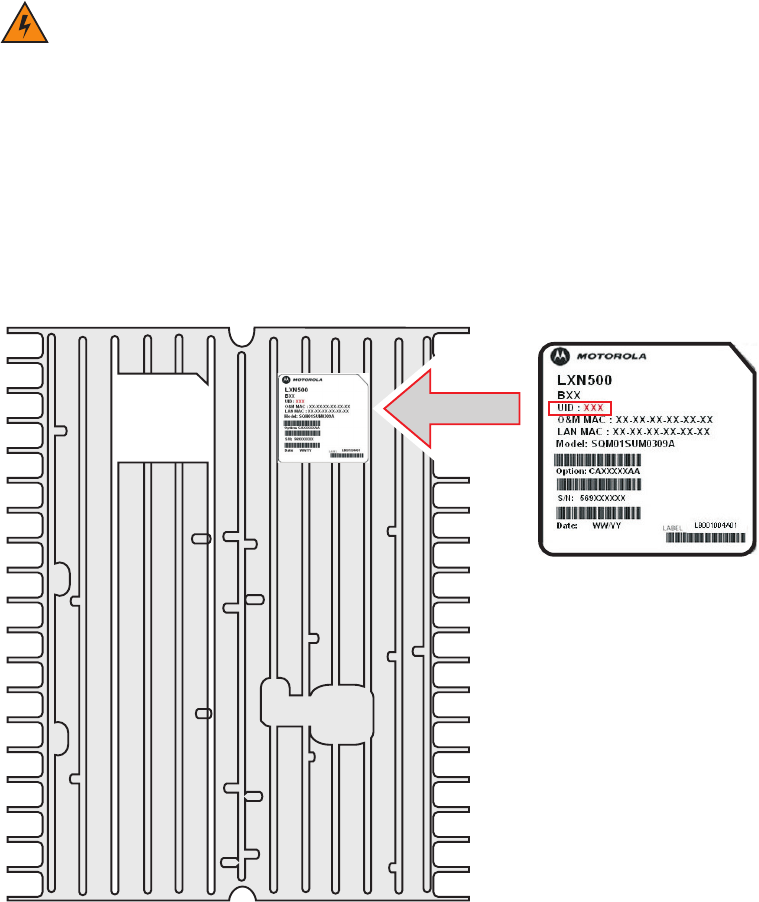
Obtaining the Unit Identification (UID) Number
The Unit Identification (UID) number is required throughout the configuration process of the LXN 500.
The UID can be found on the information label at the bottom side of the LXN 500.
Figure 2-1
LXN 500 Information Label
WARNING!During operation the LXN 500 enclosure surface can become hot. Before using the LXN 500, refer
to the touch hazard warning label located on the upper side of the enclosure.

MN003563A01-B
Operation and Configuration
18 Send Feedback
Powering On
1. Start the car engine.
2. Press and hold the Power button for four seconds and release when all LEDs begin to blink
green.
Result: During boot-up, all LEDs blink green for about four minutes and then remain steady green
indicating a successful boot.
Powering Off
Starting Shutdown Sequence
1. Press and hold the Power button for four seconds.
Result: all LEDs on the front panel blink orange, to indicate power down, and than turn off.
Forcing Power Off
1. Press and hold the Power button for 15 seconds.
Result: all LEDs on the front panel turn off.
IMPORTANT - When using the LXN 500 inside a vehicle, power on only after engine start.
- To enable a successful boot-up, remove all USB devices connected to the LXN
500 before powering on.
19
MN003563A01-B
Operation and Configuration
Send Feedback
What is Required for Configuration
Before starting to configure the LXN 500, obtain the following:
1. LXN 500 power supply unit.
2. Ethernet cable.
3. USIM cards for your mobile devices with information list that includes: identity, authentication,
operator code etc.
4. Operation information given by your authorities: frequency band, bandwidth, either downlink central
frequency in MHz or DL EARFCN, physical and logical cell ID and PLMN.
5. Laptop computer (With Google Chrome browser installed), mouse and keyboard.
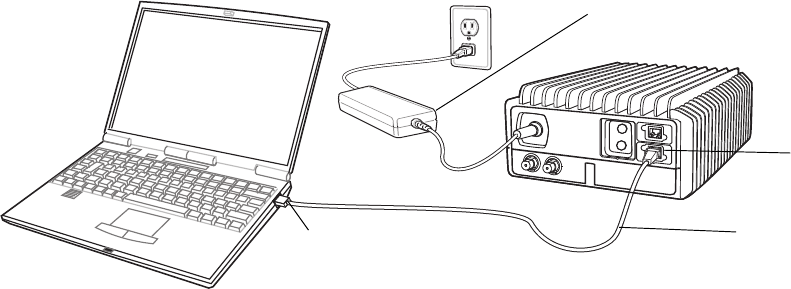
Connecting the LXN 500 to a Laptop
The LXN 500 is configured by using Google Chrome to browse and access the LXN 500 Operation &
Management (O&M) site on the LXN 500.
IMPORTANT Before connecting the LXN 500 to a laptop, verify the laptop is disconnected from any wired
LAN connections and disable all wireless LAN connections.
Perform this procedure to connect the LXN 500 to a laptop.
Procedure:
1. Obtain the LXN 500 UID number from the information label on the LXN 500 (See Figure 2-1).
2. Set the parameters of the Local Area Connection of the laptop as described below.
For example: in Windows 10; in the search box on the taskbar, type View network connections,
and then select View network connections → Properties → Networking tab → under This
connection uses the following items, select Internet Protocol Version 4 (TCP/IPv4) →
Properties → and set the following:
•
Use the following IP address: 10.98.66.2
•
IP address, Subnet musk: 255.255.0.0
•
Default gateway: 10.98.66.<UID>
3. Connect an Ethernet Cable between the LAN Port of a laptop and the MNG Port on the LXN 500.
4. Connect the Power Supply Unit to the LXN 500.
5. Power on the LXN 500 (See Powering On on page 18).
Figure 2-2
Connecting the LXN 500 to a Laptop
PWR
MNG Port
LAN Port Ethernet Cable
Power Supply Unit
MN003563A01-B
Operation and Configuration
20 Send Feedback
6. On the laptop, launch Google Chrome and log-on to: https://10.1.<UID>.8
Result: The LXN 500 O&M Configuration - Sign In screen is displayed (See Figure 2-3).
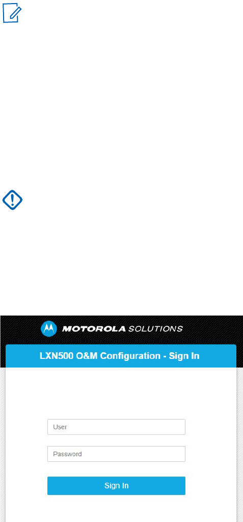
Signing In
Perform this procedure to sign-in to the LXN 500 O&M Management site.
Procedure:
1. Connect the LXN 500 to a laptop (See Connecting the LXN 500 to a Laptop on page 19).
In the LXN 500 O&M Configuration - Sign In Screen, enter User and the corresponding Password and
click Sign In.
Figure 2-3
LXN 500 O&M Configuration - Sign In Screen
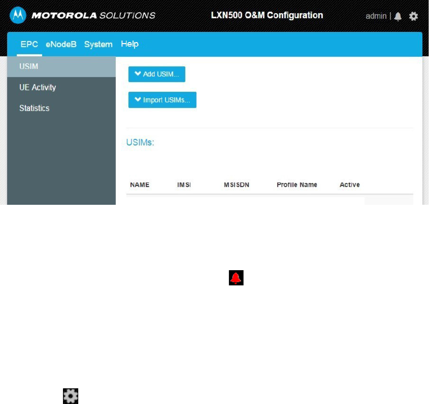
Result: The EPC tab of the LXN 500 O&M Configuration screen is displayed showing admin on the
upper right side of the screen.
NOTE On first connection, you may be required to follow a self signed certificate warning that
appears on the browser screen. When a warning appears on the screen, click
ADVANCED and then click Proceed to and the ip address shown.
IMPORTANT When signing in for the first time, sign in with the default Administrator password - enter:
User: admin
Password: M0t0r0laAdm1n1!
Change the default password upon signing in for the first time.
M0t0r0laAdm1n1!
admin
21
MN003563A01-B
Operation and Configuration
Send Feedback
Figure 2-4
EPC Tab
Viewing System Notifications
During operation, users are notified of incoming events or alerts by LXN 500 management system.
Upon an incoming event or alert, the bell icon on the upper right side of the screen, change color
from gray to red. To view details on event or alert, click the bell and follow a link.
Signing Out
Perform this procedure to sign-out from the LXN 500 O&M Configuration site.
Procedure:
1. Click on and select Logout.
Result: The Log In screen is displayed.

MN003563A01-B
Operation and Configuration
22 Send Feedback
Account Management
LXN 500 O&M Configuration is managed by an administrator.
The administrator assigns access password to a set of management permissions to each user role.
User Roles and Management Permissions
The LXN 500 supports the following user roles:
•
Administrator: user who can administrate, configure, set subscribers and modify the system on an
agency level.
•
Technician: user who can view diagnose and set technical aspects of the system on an agency
level.
•
Operator (default): user who operate the LXN 500 on an agency level and can monitor system
data.
Table 2-1 describes the management permissions assigned to each user role in the LXN 500.
Table 2-1
Management Permissions Assigned to Each User Role in the LXN 500
Action
Management Permissions
Administrator Technician Operator
USIM (Add, Change Status, Import, Delete, Delete all) (See
Adding a
Single Subscriber (UEs) on page 24
)
Yes Yes No
View Logs/Statistics of Subscriber (UE) Activity (See
UE Activity on
page 28
)
Yes Yes Yes
Set the eNodeB Configuration (See
Setting the eNodeB on page 30
)Yes Yes No
View Logs/Statistics of EPC (See
Statistics on page 29
) Yes Yes Yes
View PLMN in System Configuration (See
PLMN Settings on page 31
)Yes Yes No
Change Configuration of PLMN (See
PLMN Settings on page 31
)Yes Yes No
View System Configuration (See
Setting the System on page 31
) Yes Yes Yes
View Communication Diagnostics (See
PLMN Settings on page 31
)Yes Yes No
Perform Communication Ports Diagnostics (See
Communication
Diagnostics on page 33
)
Yes Yes No
View System Health Diagnostics (See
PLMN Settings on page 31
and
Performing Diagnostics on page 33
)
Yes Yes Yes
Backup/Restore LXN 500 servers Yes No No
View Battery Diagnostics Info (See
Battery Diagnostics on page 38
) Yes Yes Yes
Perform LED Test (See
LEDs Test on page 41
)YesYesNo
View Logs/Statistics of System Diagnostics (See
System Logging on
page 41
)
Yes Yes Yes
Restart the LXN 500 (See
Resetting the LXN 500 on page 62
)Yes Yes No
Restart the eNodeB (See
Resetting the eNodeB on page 63
)Yes Yes No
23
MN003563A01-B
Operation and Configuration
Send Feedback
Passwords
The LXN 500 requires a sign in password to monitor, configure, administrate and service the LXN 500.
Passwords are based on three type of user roles and are not granted on personal bases.
Each user role is initially assigned with a default password that can only be changed by an administrator.
Table 2-2 shows the default password assigned to each user role.
Table 2-2
Default Password Assigned to Each User Role
Changing the User Password
Perform this procedure to change a password to a user role:
Procedure:
1. Log in as an Administrator.
2. Click on and select Change Password.
3. Select the User → enter the old password → enter a new password → reconfirm the new password
and click Change.
When changing a password note that a valid password must comply with the following rules:
•
Use at least 15 characters in length password
•
Use at least one uppercase character
•
Use at least one lower-case character
•
Use at least one numeric character
•
Use at least one special character
•
When changing a password, change at least 8 of the total number of characters.
IMPORTANT To avoid a security breach, it is recommended to change passwords upon signing in for
the first time. Change passwords frequently and establish a security policy that
determines a maximum password duration.
User Role
Administrator Tech n i cia n Operator
User
admin tech user
Password
M0t0r0laAdm1n1! M0t0r0laT3ch12! MotorolaLXN5001!
IMPORTANT Changing a user role password does not effect other access permissions or
application passwords in the LXN 500.
MN003563A01-B
Operation and Configuration
24 Send Feedback
Adding a Single Subscriber (UEs)
Perform this procedure to add a new subscriber (User Equipment-UEs) to the LXN 500.
Procedure:
1. Sign in to the LXN 500 O&M Configuration site (See Signing In on page 20).
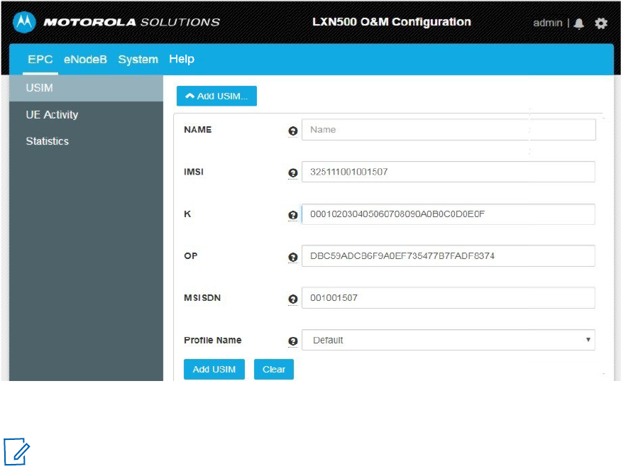
2. In the LXN 500 O&M Configuration screen, on the EPC tab, click the Add USIM... button.
Result: The add USIM fields are displayed.
Figure 2-5
Add USIM Fields
3. Enter the information of the USIM.
•
In the NAME field, enter the logical name of the USIM
•
In the IMSI field, enter the unique identifier of the USIM
•
In the K field, enter transport key
•
In the OP field, enter the operator code
•
In the MSISDN field, enter the Mobile Station International Subscriber Directory Number (up to 15
digits)
•
In the Profile Name field, set to Default.
NOTE The USIM information is usually provided by your USIM cards provider with the USIM
cards package.
25
MN003563A01-B
Operation and Configuration
Send Feedback
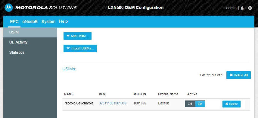
4. Click Add USIM to add another USIM to the LXN 500 or Clear to clear the current information
displayed in the fields.
Result: The newly added USIM is displayed in the table on the EPC tab.
Figure 2-6
USIM is Displayed in a Table on the EPC Tab Screen
5. Turn off your mobile device, install the USIM card and turn on the mobile device.
6. Refer to Provisioning the Mobile Device (UE) on page 45 to set your mobile device to operate with
the LXN 500.
Deactivating/Activating Subscriber
The deactivation of a subscriber temporary deny service to that subscriber.
Perform this procedure to deactivate or activate a subscriber.
Procedure:
1. Sign in to the LXN 500 O&M Configuration site (See Signing In on page 20).
2. On the EPC screen, click the Off / On switch in the Active column of the relevant USIM.
MN003563A01-B
Operation and Configuration
26 Send Feedback
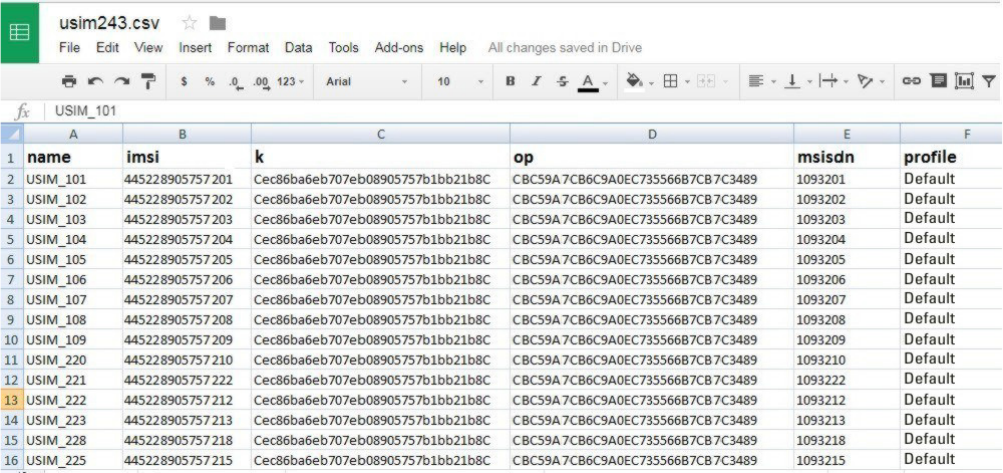
Importing Subscribers From .csv File
Perform this procedure to import a list of subscribers from a .csv file.
Procedure:
1. Sign in to the LXN 500 O&M Configuration site (See Signing In on page 20).
2. Click Import USIMs...
3. Click download template to download an empty template .csv file to your hard drive.
4. Open the .csv file using Microsoft Office Excel or any text editor.
5. Edit the respective information for each USIM (See Adding a Single Subscriber (UEs) on page 24)
and save the .csv file on your hard drive.
Figure 2-7
An Example of .csv file with list of USIMs
27
MN003563A01-B
Operation and Configuration
Send Feedback
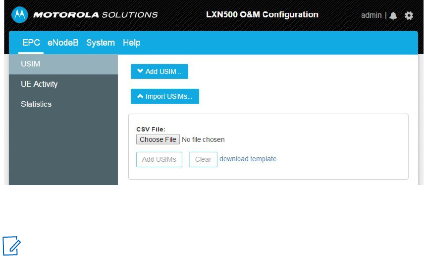
6. On the EPC tab, click the Import USIMs... button.
Figure 2-8
Importing Subscribers from .csv File
7. Click the Choose File button, navigate to the .csv file and click Open.
Result: The list of USIMs appears on the screen.
8. Add the USIMs by clicking the Apply button.
9. Click the save icon or Delete All to remove all USIM entries.
10. Turn off your mobile devices, install the USIM cards and turn on the mobile devices.
11. Set your mobile devices to operate on 4G (LTE) network.
Deleting Subscriber
Perform this procedure to remove existing USIM from the LXN 500.
Procedure:
1. Sign in to the LXN 500 O&M Configuration site (See Signing In on page 20).
2. On the EPC tab, click the X Delete button to delete a USIM.
3. Click Ok to confirm the delete operation.
Deleting All Subscribers
Perform this procedure to remove all existing USIM from the LXN 500.
Procedure:
1. Sign in to the LXN 500 O&M Configuration site (See Signing In on page 20).
2. On the EPC tab, click the Delete All button to delete all USIMs.
3. Click Ok to confirm the delete operation.
NOTE USIM fields with invalid information are highlighted in red. Duplicated records are
highlighted in blue.
MN003563A01-B
Operation and Configuration
28 Send Feedback
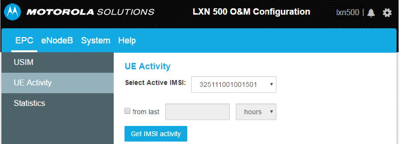
UE Activity
The UE Activity option displays a historical summary of communication activities performed by a
subscriber.
Perform this procedure to display a historical summary of communication activities performed by a
subscriber.
Procedure:
1. Sign in to the LXN 500 O&M Configuration site (See Signing In on page 20).
2. On the EPC tab, click UE Activity.
3. Select a subscriber from the Select Active IMSI: drop list.
4. In the from last field, enter a number and select hours or days.
5. Click the Get IMSI activity button to display a historical summary of communication activities.
Figure 2-9
UE Activity Screen
29
MN003563A01-B
Operation and Configuration
Send Feedback
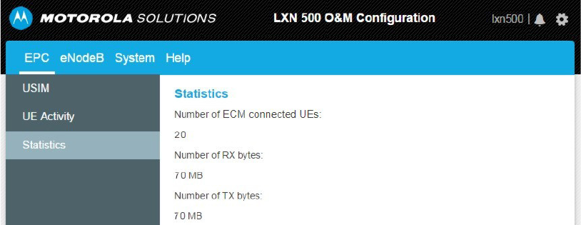
Statistics
The statistics screen displays the following information:
•
Number of ECM connected UEs currently linked to LXN 500
•
The accumulated bytes received by the LXN 500 from time of manufacture.
•
The accumulated bytes transmitted by the LXN 500 from time of manufacture.
Figure 2-10
Statistics Screen
MN003563A01-B
Operation and Configuration
30 Send Feedback
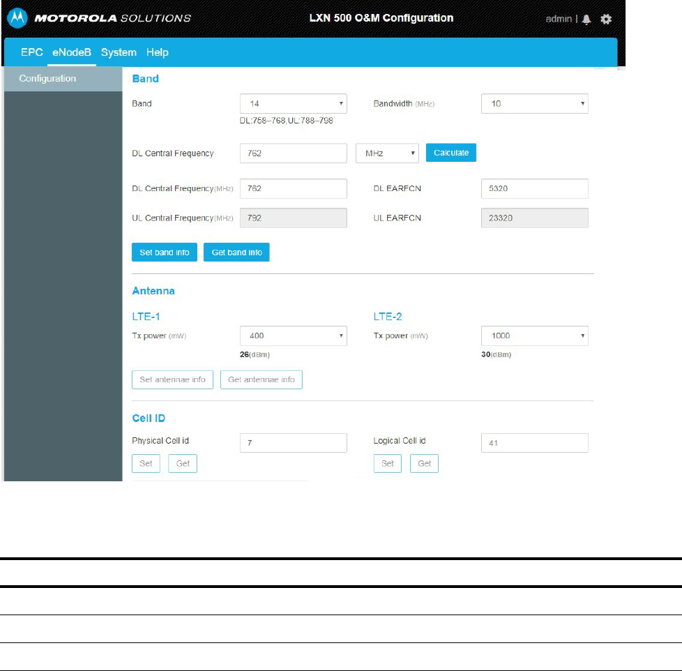
Setting the eNodeB
The eNodeB is the part of the LXN 500 that sends and receives radio transmissions and signaling from
and to the mobile devices. The eNodeB process the LTE analogue and digital over-the-air interface
signals.
Perform this procedure to configure the eNodeB.
Procedure:
1. Sign in to the LXN 500 O&M Configuration site (See Signing In on page 20).
2. Click the eNodeB tab.
Result: The eNodeB screen is displayed.
Figure 2-11
eNodeB Screen
3. In the Bandwidth field, select the required bandwidth.
Table 2-3
eNodeB Band Configuration
Band Bandwidth (MHz) Uplink / Downlink Frequency Range
14
5, 10 UL:788 - 798, DL: 758 - 768
20
5, 10, 20 UL: 832 - 862, DL: 791 - 821
28
5, 10, 20 UL: 723 - 748, DL: 778 - 803
31
MN003563A01-B
Operation and Configuration
Send Feedback
NOTE The range of band 28, according to 3GPP standard is 45 Mhz. The LXN 500 supports a partial
range of 25 Mhz of the full range.
4. Enter the DL (Downlink) central frequency MHz (in 0.1 MHz precision) or DL EARFCN and click the
Calculate button to automatically populate all center frequency fields.
5. Click the Set band info button to save changes or Get band Info to populate the field with the last
saved values.
6. In the Antenna section of the eNodeB tab, set identical Tx power (Transmit power in mW) to LTE1
and LTE2 antenna ports (See Figure 1-3 on page 1-16).
NOTE Tx power range can be set from 1 to 1000 mW RMS (0 to 30 dBm).
7. Click the Set antenna info button to save changes Get antenna Info to populate the field with the
last saved values.
8. In the Physical Cell ID field, enter the Physical Cell ID of the LXN 500 (Range 0-503) and click the
Set to save changes or Get to restore the last saved value.
CAUTION Physical Cell ID is generally unique number used to identify each base transceiver station
(BTS) within a LTE network. When using more than one LXN 500 in a LTE network, DO NOT
set identical Physical Cell ID to two LXN 500s or any linked base station that may have
overlapping radio coverage area.
9. In the Logical Cell ID field. Enter the Logical Cell ID and click the Set to save changes or Get to
restore the last saved value.
Setting the System
The System tab is used by administrators and technicians to diagnose, troubleshoot and show status of
the LXN 500 hardware and software.
PLMN Settings
A public land mobile network (PLMN) is a network that is established and operated by an administration
for the specific purpose of providing land mobile telecommunications services to the public.
A PLMN is identified by the Mobile Country Code (MCC) and the Mobile Network Code (MNC). Each
operator providing mobile services has its own PLMN. When the LXN 500 is interconnect other
networks, the PLMN interconnect with other PLMNs to create links between providers.
Perform this procedure to set the PLMN of the LXN 500:
Procedure:
1. Sign in to the LXN 500 O&M Configuration site (See Signing In on page 20).
2. Click the System tab.
3. Click PLMN.
Result: The PLMN Settings screen is displayed.
4. In the MCC field, enter the MCC number
5. In the MNC field, enter MNC number
6. Click the Set button to save changes or Get to populate the field with the last saved values.
Result: After setting a new PLMN value and clicking Set, the eNodeB restarts. This procedure takes
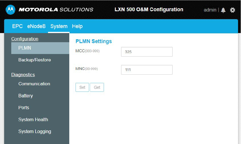
MN003563A01-B
Operation and Configuration
32 Send Feedback
a few minutes and ends when all LEDs illuminate steady green. The restart process can also be
tracked on the System Health page (See System Health on page 40).
Figure 2-12
PLMN Settings Screen
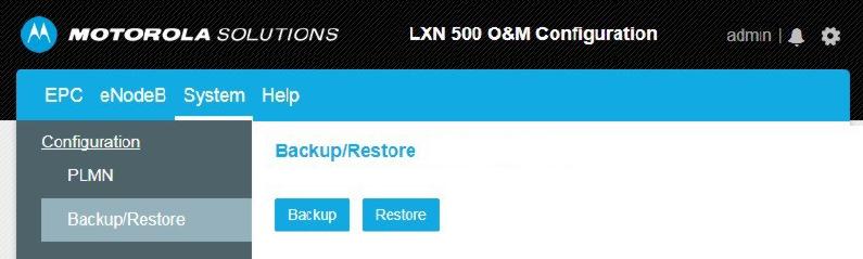
Backing-up and Restoring
During operation, servers or applications of the LXN 500 might fail to power-up or get stuck as a result of
improper system shutdown or data corruption.
Backing-up and restoring enables the system to recover the last backed up version of servers and
applications to restore operation.
Perform this procedure to Back-up and Restore servers and applications of the LXN 500.
Procedure:
1. Sign in to the LXN 500 O&M Configuration site (See Signing In on page 20).
2. Click the System tab.
3. Click Backup/Restore.
Result: The Backup/Restore screen is displayed.
33
MN003563A01-B
Operation and Configuration
Send Feedback
4. Click Backup to backup parameters you configured using the Q&M (excluding IMSIs) or Restore to
use the last saved settings of your servers and applications.
Figure 2-13
Backing-up and Restoring Servers and Applications
Performing Diagnostics
Follow procedures below to perform diagnostics to the LXN 500 unit.
Communication Diagnostics
The communication diagnostics is used for testing the 4G (LTE) communication with the LXN 500.
The test is performed between the LXN 500 and any available LTE mobile device connected to the LXN
500.
To perform communication diagnostics, the LXN 500 is using the Iperf application.
Iperf application is a cross-platform tool used for network performance measurement.
Iperf application must also be installed on the mobile device used for the test. The iperf application is
securely distributed through the Google Play store.
MN003563A01-B
Operation and Configuration
34 Send Feedback
Iperf has client and server functionality, and creates data streams to measure the throughput between
the two ends - the mobile device functions as a server and the LXN 500 as client.
Figure 2-14
Communication Diagnostics
Built in Test
The Built in Test is a preset network performance test performed between the LXN 500 and the mobile
device. The test diagnose the UDP capacity between the LXN 500 and the mobile device at 5mbps.
Perform this procedure to test the LXN 500 communication.
Procedure:
1. Click Communication to test the LXN 500 communication.
Result: The Communication test screen is displayed.
2. Check Built in Test.
3. Check Short for a quick 10 seconds communication test or Continuous (Hours) and enter the
required duration of the test.
4. In the IP Address field, enter the IP address of the mobile device used for the test.
NOTE Most Android devices display the IP address of the device under: Settings → About → Status →
IP Address.
5. Enter the number of communication port used for the test (Default port number is 5001).
NOTE If you do not know the port number, leave this field empty.
35
MN003563A01-B
Operation and Configuration
Send Feedback
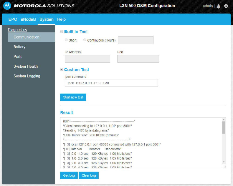
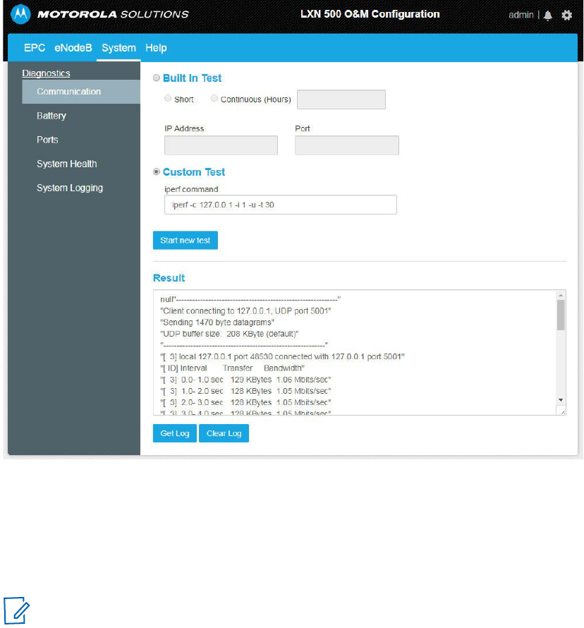
6. Click the Start new test button and wait for the results to appear in the Result window.
Result: The test results are displayed in the Result window. The output contains a time-stamped
report of the amount of data transferred and the measured throughput.
7. Click Get Log to download a file with the latest test output or Clear Log to erase the log file created
for the last test and clear the screen.
Figure 2-15
Communication Test Screen
Custom Test
The Custom Test is a network performance diagnostics between the LXN 500 and a mobile device. The
diagnostics is built out of a selection of tests configured by a command line. The custom test command
also supports pinging between LXN500 and mobile devices to test the connection.
Perform this procedure to test the LXN 500 communication.
Procedure:
1. Click Communication to test the LXN 500 communication.
Result: The Communication test screen is displayed.
2. Check Custom Test.
NOTE Before starting the Custom Test, make sure the mobile device is using iPerf2 client
application.

MN003563A01-B
Operation and Configuration
36 Send Feedback
3. In the iperf command field, edit the iperf default command line to customize the communication
tests using the following command line arguments:
Command Line Structure
iperf [-s|-c <Host>] [-u] [-p <Port>] [-B <Interface>] [-c] [-b <Bandw>[kKmM]] [-l <Length>] [-t <Time>] [-d]
[-r] [-L <Port>] [-h]
Table 2-4
iperf Command Line Options
Command Line Option Description
Client/Server
-u, --udp Uses UDP instead of TCP.
-p, --port <Port> Connects with or expects data packets on this port (default: 5001).
-B, --bind <Interface> Permits the connection only via the specified interface (IP address or
interface name).
Server Specific
-s, --server Starts iPerf in server mode and waits for an iPerf client to contact it.
Client specific
-c, --client <Host> Starts iPerf in client mode and connects with the iPerf server <Host>
(IP address or DNS name).
-b, --bandwidth
<Bandw>{kKmM}
Limit the [down]/up-stream bandwidth when analyzing a UDP
connection. This Is specified as kilobytes (kK) or megabytes (mM)
per second (default: 1 Mbps).
-l, --len <Length> Sets the length of the UDP data packets.
-t, --time <Time> Sets the duration of the connection in seconds (default: 10 seconds).
-d, --dualtest The test is bidirectional: the iPerf server and client send and receive
at the same time.
-r, --tradeoff The test is sequential: the iPerf server and client send and receive
one after the other.
-L, --listenport <Port> Specifies the port where the device in bidirectional mode expects to
receive data packets from the remote iPerf server (default: 5001).
Miscellaneous
-h, --help Outputs the help text.
Using ping Ping Command Line Structure:
ping [-t] [-a] [-n count] [-l size] [-f] [-i TTL] [-v TOS] [-r count] [-s count]
[[-j host-list] | [-k host-list]] [-w timeout] [-R] [-S srcaddr] [-4] [-6]
target_name

37
MN003563A01-B
Operation and Configuration
Send Feedback
4. Start the i Perf application on the mobile device.
5. Click the Start new test button and wait for the results to appear in the Result window.
Result: The test results is displayed in the Result window. The output contains a time-stamped
report of the amount of data transferred and the throughput measured.
6. Click Get Log to display the results of the last test or Clear Log to remove the lo
-t Ping the specified host until stopped.
•
To see statistics and continue - type Control-Break;
•
To stop - type Control-C.
-a Resolve addresses to hostnames
-n count Number of echo requests to send.
-l size Send buffer size.
-f Set Don't Fragment flag in packet (IPv4-only).
-i TTL Time To Live.
-v TOS Type Of Service (IPv4-only).
-r count Record route for count hops (IPv4-only).
-s count Timestamp for count hops (IPv4-only).
-j host-list Loose source route along host-list (IPv4-only).
-k host-list Strict source route along host-list (IPv4-only).
-w timeout Timeout in milliseconds to wait for each reply.
-R Trace round-trip path (IPv6-only).
-S srcaddr Source address to use (IPv6-only).
-4 Force using IPv4.
-6 Force using IPv6.
Command Line Option Description
Client/Server
-u, --udp Uses UDP instead of TCP.
-p, --port <Port> Connects with or expects data packets on this port (default: 5001).
-B, --bind <Interface> Permits the connection only via the specified interface (IP address or
interface name).
Server Specific
-s, --server Starts iPerf in server mode and waits for an iPerf client to contact it.
MN003563A01-B
Operation and Configuration
38 Send Feedback
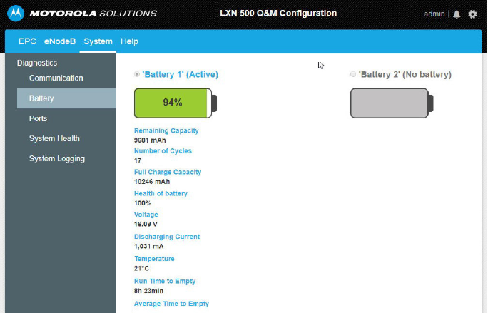
Battery Diagnostics
The Battery Diagnostics section enables to view the current status of each of the batteries installed
inside the LXN 500 backpack (Future option of the LXN 500).
Perform this procedure to view the current status of the LXN 500 backpack batteries.
Procedure:
1. Sign in to the LXN 500 O&M Configuration site (See Signing In on page 20).
2. Click the System tab.
3. From the Diagnostics menu, select Battery.
4. Click ’Battery 1’ or ’Battery 2’ to switch and view each battery status.
Result: The following battery indications may display:
•
OFF - No battery or depleted battery
•
GREEN - Battery is active and its capacity is more than 50%
•
ORANGE - Battery capacity is 10% to 50%
•
RED - Battery capacity is less than 10%
Figure 2-16
Battery Diagnostics
Ports Test
Perform this procedure to test the LXN 500 communication ports.
1. Sign in to the LXN 500 O&M Configuration site (See Signing In on page 20).
2. Click the System tab.
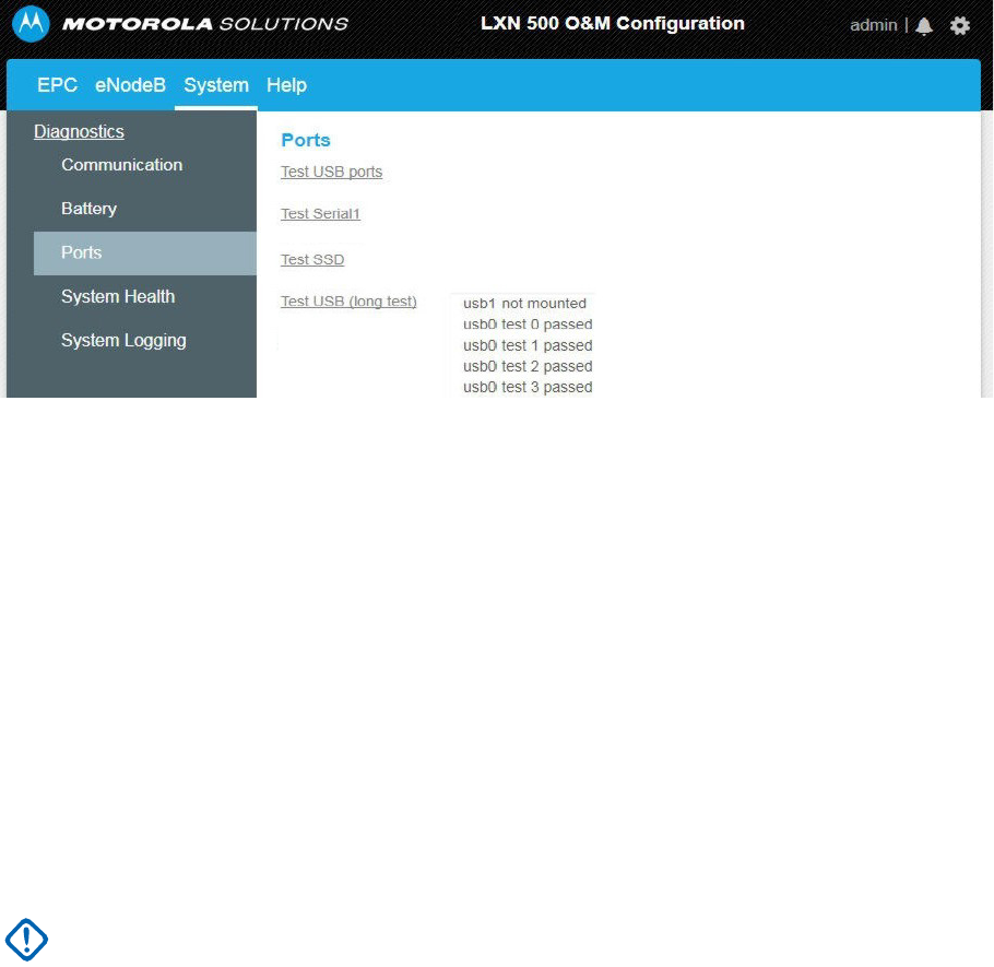
39
MN003563A01-B
Operation and Configuration
Send Feedback
3. Click Ports.
Result: The Ports screen is displayed.
Figure 2-17
Ports Test Screen
4. Click on each of the following port tests to start:
•
Test USB ports: This test briefly checks the external USB ports of the LXN 500.
1. To perform this test, on the front panel of the LXN 500, remove the four screws that hold the
protective covers of the USB ports (See Figure 1-2).
2. Plug-in a mass storage flash drive(s) to the USB port.
3. Click Test USB ports.
Result: The LXN 500 exchanges data for 10 seconds with the storage device and indicts
SUCCESS or FAIL.
•
Test Serial1: This test checks the internal RS232 communication ports that interconnect boards inside the
LXN 500.
•
Test SSD: This test checks the hard drives of the LXN 500. Click Test SSD and wait for SUCCESS or FAIL
indication.
•
Test USB (long test): This test extensively checks the USB ports of the LXN 500.
1. To perform this test, on the front panel, remove the four screws that hold the protective
panels of the USB ports.
2. Plug-in a FAT32 only flash drive(s) to the USB port.
3. Click Test USB ports.
Result: The LXN 500 exchanges data for one hour with the storage device and indicts
SUCCESS or FAIL.
4. Reinstall the four screws that hold the protective panels of the USB ports.
IMPORTANT This test may last up to one hour and once started cannot be stopped.
MN003563A01-B
Operation and Configuration
40 Send Feedback
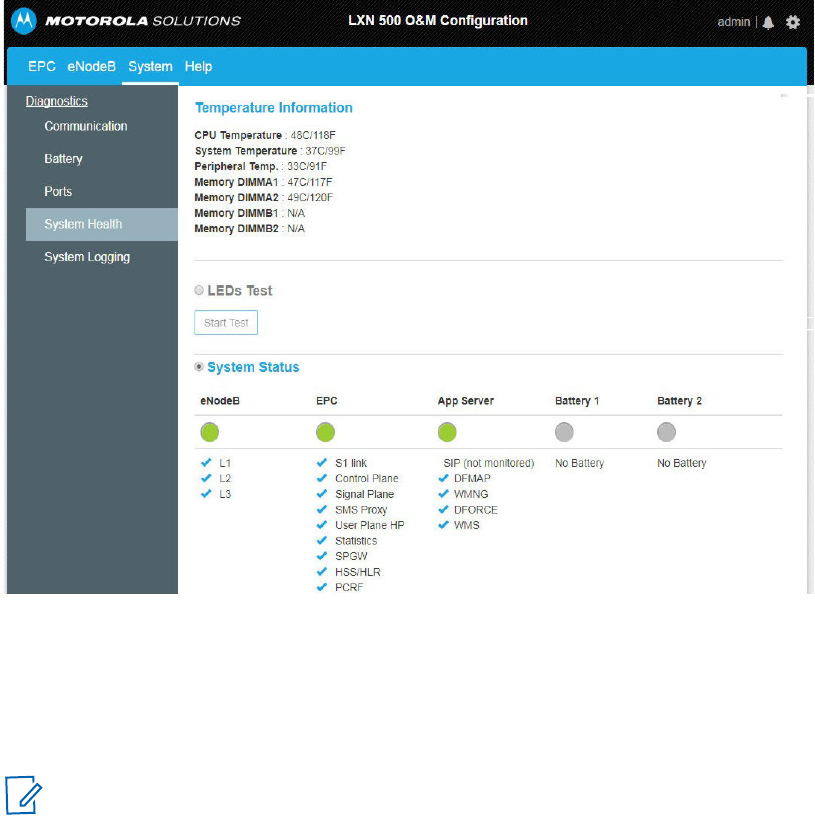
System Health
The System Health screen is used to provide LXN 500 temperature information and system status.
Perform this procedure to check the LXN 500 system health.
1. Sign in to the LXN 500 O&M Configuration site (See Signing In on page 20).
2. Click the System tab.
3. Click System Health to test the LXN 500 system health.
Result: The System Health screen is displayed.
Figure 2-18
System Health Screen
Temperature Information
The Temperature Information section displays the temperature of critical components inside the LXN
500. Temperature Information readings are mostly used by maintenance and instillation personnel to
troubleshoot the LXN 500.
NOTE Ambient temperatures beyond 140°F (60°C) will force the LXN 500 to shutdown.
41
MN003563A01-B
Operation and Configuration
Send Feedback
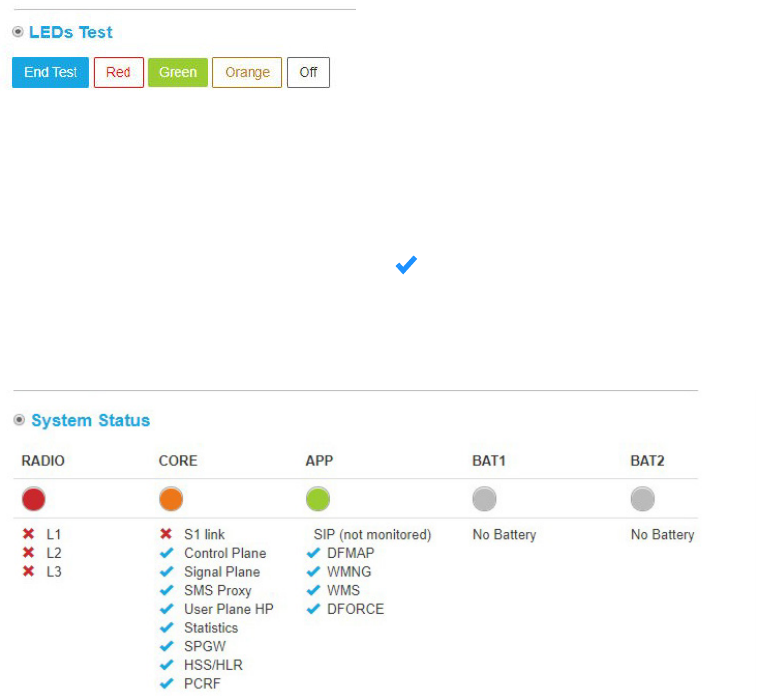
LEDs Test
The LEDs Test enables to test the illumination of the front panel LEDs. During this test, the LEDs will not
display the current status of the LXN 500.
Perform this procedure to test the front panel LEDs of the LXN 500.
1. On the System Health screen, check LEDs Test.
2. Click on a color button.
Result: The front panel LEDs illuminate in the selected color.
Figure 2-19
LEDs Test
System Status
The System Status section displays technical information related to the LXN 500 system health.
The indications shown on this section are identical to these of the status LEDs on the front panel of the
LXN 500. Detailed health status of related software or hardware sections is listed below each LED.
Functioning components are marked by and faulty by X.
The System Status information is mostly used by maintenance personnel to perform component level
troubleshoot of the LXN 500.
Figure 2-20
System Status
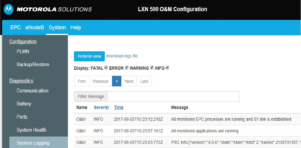
System Logging
The LXN 500 includes an automatic logging service that registers the following system information:
•
Error Events
•
Warnings
•
General Information
•
Developers Debug Information
Perform this procedure to generate, view and manage an event log:
1. Sign in to the LXN 500 O&M Configuration site (See Signing In on page 20).
MN003563A01-B
Operation and Configuration
42 Send Feedback
2. Click the System tab.
3. Click System Logging.
Result: The System Logging screen is displayed.
4. Click the Get System Logs button.
Result: The system log is generated and displayed.
Once a log is displayed:
•
Check the type of records to display (FATAL errors, ERRORS, WARNING, INFORMATION,
DEBUG).
•
Use the Filter Massage field to search for a string of text within the log or click on Severity or Time
to display events by severity or time.
•
Use First, Previous, Next and Last buttons to view up to five past logs.
5. Click download logs file to download.zip file with text logs.
Figure 2-21
System Logging Screen
43
MN003563A01-B
Operation and Configuration
Send Feedback
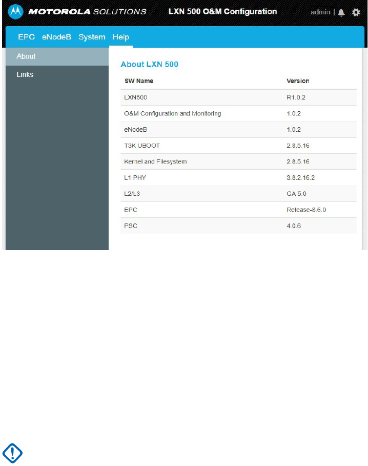
About LXN 500
The About screen enables system administrators and technicians to identify the vendors and version of
software components within the LXN 500.
Perform this procedure to generate view and manage an event log.
1. Sign in to the LXN 500 O&M Configuration site (See Signing In on page 20).
2. Click the About tab.
Figure 2-22
About LXN 500 Screen
Configuring the DragonForce Server
Perform this procedure to Configure the DragonForce Server:
1. Sign in to the LXN 500 O&M Configuration site (See Signing In on page 20).
2. Click the Help tab.
3. Click Links → DF.
4. Enter User Name: admin and Password: [DF]Motorola1
5. Click Log In.
Result: The DragonForce Log In screen is displayed.
IMPORTANT To avoid a security breach, it is recommended to change the password upon signing in
for the first time. For changing the password, refer to DragonForce documentation.
MN003563A01-B
Operation and Configuration
44 Send Feedback
Figure 2-23
DragonForce Log In Screen
6. To configure users and groups, refer to DragonForce documentation.
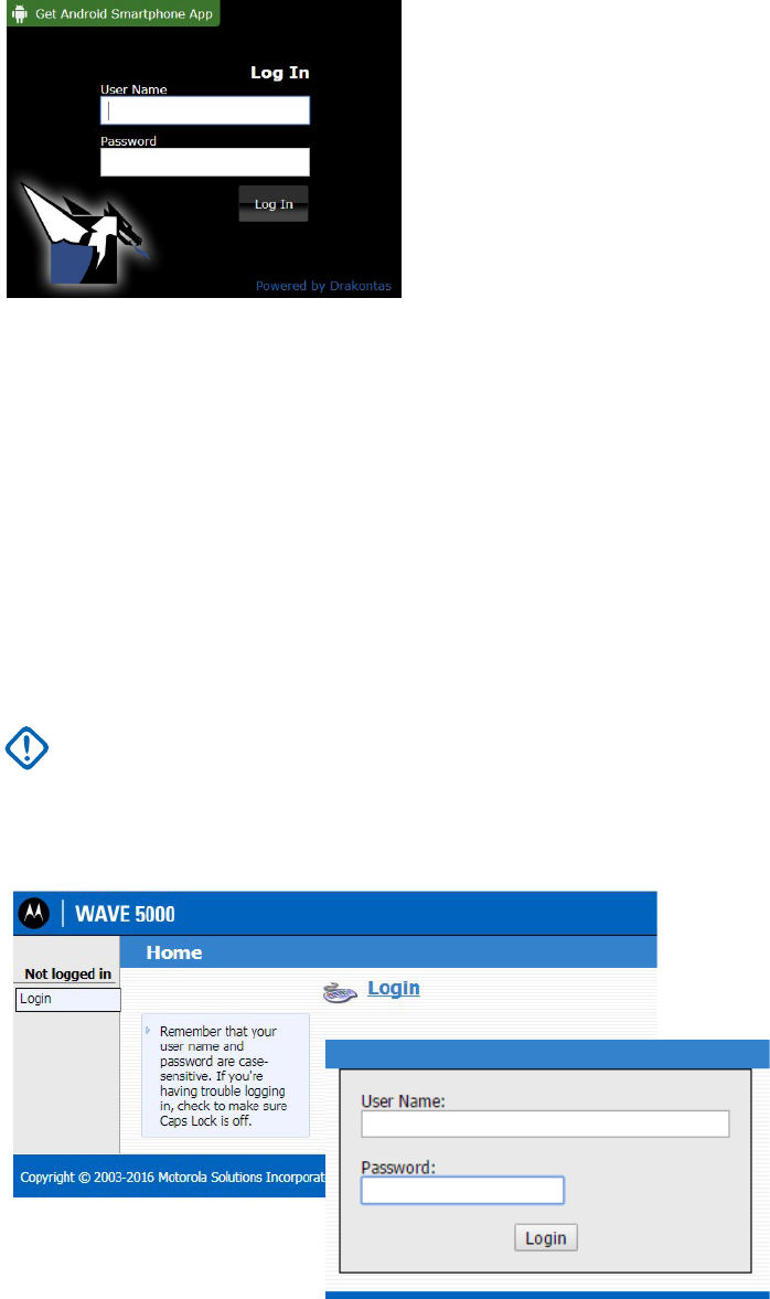
Configuring the WAVE 5000 Server
Perform this procedure to Configure the WAVE 5000 Server:
1. Sign in to the LXN 500 O&M Configuration site (See Signing In on page 20).
2. Click the Help tab.
3. Click Links → WAVE.
4. Click Login.
Result: The WAVE Server Login screen is displayed.
Figure 2-24
WAVE 5000 Server Log In Screen
5. Enter User Name: administrator and Password: LXN500M0t0r0law5k!
6. Click Login.
7. To configure users and talkgroups, refer to WAVE server documentation.
IMPORTANT To avoid a security breach, it is recommended to change the password upon signing in
for the first time. For changing the password, refer to WAVE 5000 Server
documentation.

45
MN003563A01-B
Operation and Configuration
Send Feedback
Provisioning the Mobile Device (UE)
Perform this procedure on the mobile device to connect the mobile device to the LXN 500:
1. From the home screen of the mobile device, click Settings → ...More → Cellular networks →
Access Point names → →Edit access point → set Name to internet set APN type to
default → → Save.
2. From the home screen of the mobile device, click Settings → ...More → Cellular networks →
Network Mode → select LTE Only.
3. From the home screen of the mobile device, click Settings → Security → Install from SD Card→
Network Operators → set PLMN ID as in the LXN 500 → Connect.
4. Contact Motorola Solution Support Center to download and install WAVE Push-to-Talk (PTT)
application on the mobile device.
5. Download and Install WAVE 5000 certificate:
•Contact Motorola Solution Support Center to download and save the w5kext.cer file on the
mobile device.
•From the home screen of the mobile device, click Settings → Security → Install from SD
card → search and click on the w5kext.cer file → OK.
6. Download and Install DForce Client application:
•Contact Motorola Solution Support Center to download and save the DForce * .apk file on the
mobile device.
•From the home screen of the mobile device, click Settings → Security → Install from SD
card → search and click on the DForce * .apk file → OK.
+

47
MN003563A01-B
Vehicle Installation
Send Feedback
Vehicle Installation
This section describes the tools and equipment, planning requirements and product inspections
necessary for a smooth installation of the LXN 500 system.
Proper planning will help to ensure that the installation is completed without difficulty and that no
damage occurs to the units or the vehicle.
Unpacking
Unpack your shipment and check the contents to ensure that you have received all the specified items.
Thoroughly inspect the equipment for shipping damage as soon as possible after delivery. Report any
damage you find to your Motorola Solutions Customer Service representative immediately.
Save the packing box and plastic bags for storage and shipping. Both the shipping box and the bags
protect the LXN 500 components from physical and electrostatic damage.
The following optional parts can be used to mount the LXN 500:
•
LXN 500
•
Four mounting brackets with 12 screws
•
13.1 feet (4 meter) power cable with 20A fuse
•
One dome antenna or two diversity antennas
•
Power protection and back-up unit (Optional)
•
Quick start guide and related documentation.
NOTE The LXN 500 is a reliable product when installed correctly. However, performance can be seriously
CAUTION LXN500 must only be deployed in a ‘restricted access location’.
impaired if it is not installed correctly. Thoughtful planning can make the difference. Product to be
installed by a service person. Before the installation, please see rating label which is located on base of
the unit .
MN003563A01-B
Vehicle Installation
48 Send Feedback
Configuration Options of Antenna Installation
The LXN 500 can be installed inside a vehicle trunk using one of the two antenna configuration options.
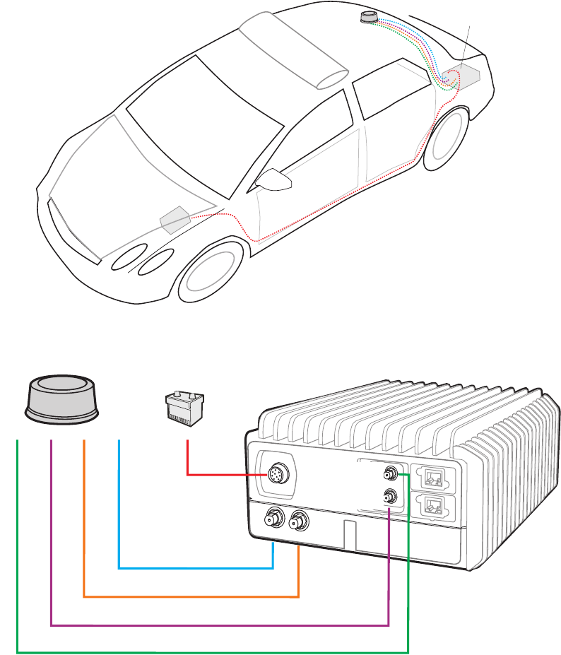
Dome Antenna Configuration
Fixed-mounted 4 ports antenna for use in public safety vehicular applications. The antenna requires a
hole in the car roof.
The antenna consists of 4 separate dedicated antennas for LTE Main (LTE1) LTE Div. (LTE2), WiFi and
GPS.
The antenna is provided with four short, flexible coaxial cables (threads) coming out of the antenna
bottom side. The 12-ft coaxial cables are provided to connect between these threads and the LXN 500
connectors. The cables are connected to the LTE1, LTE2, WIFI and GPS ports of the LXN 500.
Figure 3-1
Dome Antenna
Battery
LXN500
on trunk floor
PWR
LTE1
LTE2
GPS
WIFI
GPS
Wi Fi
LTE1
LTE2
49
MN003563A01-B
Vehicle Installation
Send Feedback
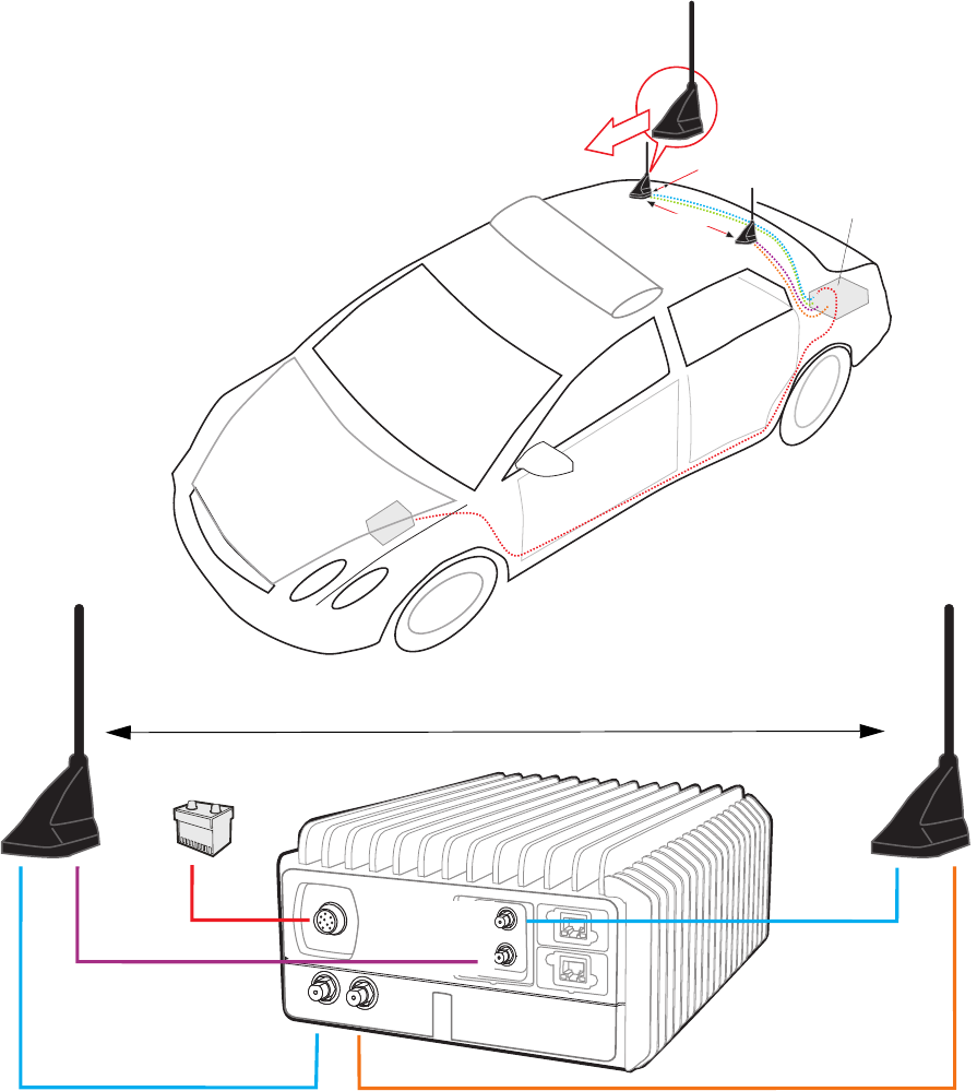
Dual Diversity Antenna Configuration
The dual diversity antenna is a layout of two diversity antennas connected in MIMO (Multiple Input,
Multiple Output) configuration.
Each antenna is provided with three short, flexible 12-ft coaxial cables (threads) coming out of the
antenna bottom side.
In one antenna, the cables are connected to the LTE1 and GPS ports of the LXN 500. In the second
antenna, the cables are connected to the LTE2 and WIFI ports of the LXN 500.
Figure 3-2
Dual Diversity Antenna
Battery
LXN500
on trunk floor
At least 8” (20 cm)
Important: Orient antenna as shown
PWR
LTE1 LTE2
GPS
WIFI
LTE Ant
GPS Ant
EVDO Ant
LTE Ant
At least 16” (40 cm)
Keep at least 16 inch (40 cm) between antennas
MN003563A01-B
Vehicle Installation
50 Send Feedback
Preparing to Install the LXN 500
Tools
The following tools and service aids are recommended for installation:
•
Set of Phillips and flat head screwdriver bits
•
T-6 through T-25 torx bits
•
Battery / air operated drill
•
Set of high speed drill bits (including 6mm bit for bracket holes)
•
Ratchet with extensions
•
Socket torque wrench
•
Socket set (Metric & Imperial)
•
Wrenches (Metric & Imperial)
•
Utility knife
•
Wire cutter
•
Volt-Ampere-Ohm meter
•
Automotive test light
•
Wire Crimp Tool
•
CAT-5e cable tester
•
Measuring tape
•
Flashlight
Materials
The hardware required to install the LXN 500 in a vehicle consists of:
•
Tie wraps
•
Electrical tape
•
Wire taps
•
Rubber grommets
•
Spare wire (8-22 gauge)
•
Variety of self tapping screws and bolts
•
Wire connectors / wire terminals / wire lugs / eyelets
Planning
Be sure to consider the following issues when planning the installation:
•
Installation location away from air bag deployment zones
•
Environmental considerations
•
Electrical guidelines

51
MN003563A01-B
Vehicle Installation
Send Feedback
•
Liquid Propane (LP) gas warning
•
Usability by driver/operator
•
Vehicle vendor instructions
•
Local vehicle authority regulations/design rules
•
LXN 500 Mounting Location
Correct positioning of the components will ensure that the LXN 500 system meets the following
requirements:
•
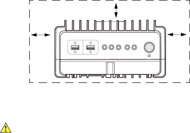
The LXN 500 is installed inside a ventilated compartment or inside a trunk. To cool the LXN 500,
allow sufficient space around the LXN 500 for free air flow (See Figure 3-3).
•
It will not injure the operator or passenger in case of an accident.
•
It does not interfere with the driver’s vision or hinder the driver when driving the vehicle.
•
Place the LXN 500 so that it can be easily removed for servicing.
•
Do not mount the LXN 500 system units and route cables where they can be kicked by the driver’s
or other passenger’s feet.
•
Verify that the mounting surface is able to support the weight of the units.
•
Select a location that permits routing the RF antenna cables as directly as possible.
•
Do not mount units on a flat or concave surface where the unit could become partially submersed
in water.
.
Ventilation
The LXN 500 is designed to operate properly in an ambient temperature range of –20°C to 60°C (-4°F to
149°F). The LXN 500 must be installed in an unobstructed location to allow proper air flow and away
from heat generating equipment such as: radio transmitters, power amplifiers or a cabin heater (See
Figure 3-3).
CAUTION When installing the LXN 500, make sure that the LXN 500 is tightly anchored to the
vehicle structure. Unstable mounts can damage the unit.
CAUTION
•
To avoid overheating of the LXN 500, do not place any object on the LXN 500.
•
To prevent overheat damage to the LXN 500, the unit is designed to automatically shut
down at 60°C (149°F)
MN003563A01-B
Vehicle Installation
52 Send Feedback
Figure 3-3
Recommended Clear Ventilation Area Around the LXN 500
Electrical Guidelines
The power range requirement for operating the LXN 500 is 9 to 33VDC. The maximal power
consumption of the LXN 500 is 70 Watts.
Be sure that the vehicle’s electrical system is in good condition. Faults in the alternator and ignition
system can be a source of severe Radio Frequency Interference (RFI) and can result in LXN 500 system
operating problems. Correct any problems in the alternator output, ignition system, and battery condition
before beginning the installation.
The vehicle must have an alternator that can produce a high-current output at low speed (below 18
m.p.h. or 29 km/h) and in an idle state. It also needs the highest rated heavy-duty battery available for
the vehicle.
If used, the input power cable of the Optional Power Protection and Back-up Unit must be directly
connected to the (+) terminal of car battery and the (-) to the car chassis (See Figure 3-6).
Ground Polarity
The LXN 500 system will only operate in negative ground electrical systems. Check the ground polarity
of the vehicle before starting the LXN 500 system installation to verify that the polarity is correct.
Accidentally reversing the polarity will not damage the LXN 500, but will cause the fuse of the power
cable to blow.
Due to advanced vehicle assembly techniques, different parts of the vehicle chassis may not be
connected to the battery negative terminal. Connecting the ground leads of several devices with a
common power supply at different locations on the chassis, may cause GROUND potential differences
between these locations and damage the LXN 500 system or any other installed equipment.
FIRST CHECK that the vehicle chassis point to which you are about to connect the negative lead is
properly connected to the battery negative terminal. If the chassis is not properly grounded, connect the
negative lead directly to the battery's negative terminal.
Clear 1.2” (30 mm)
Clear 1.2” (30 mm)
Clear 1.2” (30 mm)
Ab
SOLUTIONS
LXN 500
CAUTION The LXN 500 is installed in a vehicle with a negative-ground electrical system.
DO NOT install the LXN 500 in a vehicle with a positive-ground electrical system.
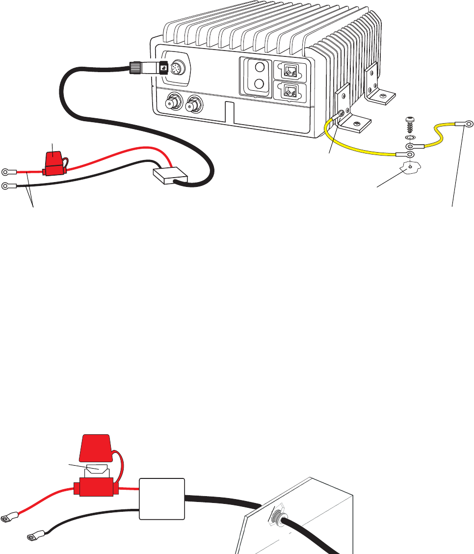
53
MN003563A01-B
Vehicle Installation
Send Feedback
When the LXN 500 and the mobile workstation are mounted on a mount or next to each other, use a
10AWG ground wire to connect between the body of the LXN 500 and other units. The ground wire ring
lugs must be connected, on one side, to one of the screw holes used to secure the LXN 500 to the
mounting bracket and on the other side to the vehicle chassis.
IMPORTANT Vehicle common ground points (chassis) should be measured against the vehicle battery
negative terminal for no more than 1/2 Ohm.
Figure 3-4
Connecting the LXN 500 to Power and Ground
Installing the Power Cable
Perform this procedure to install the LXN 500 power cable.
Procedure:
1. Determine a routing plan for the power cable, taking into consideration the location at which the unit
is to be mounted, and the location of the vehicle battery.
2. To pass the power cable through the fire wall and into the engine compartment, locate an existing
hole with a grommet in the vehicle fire wall, or drill an access hole at the desired location. Insert a
grommet inner diameter into the access hole to avoid damage to the cable (See Figure 3-5). Take
special care not to damage any existing vehicle wires.
Figure 3-5
Cable Routing into Engine Compartment
PWR
Vehicle chassis - Remove paint before connection
LXN 500
To chassis of other units
installed in the vehicle
20A Fuse
IMPORTANT Connect the red wire directly to the (+) terminal of the vehicle battery
and the black wire to the chassis of the vehicle.
Remove paint from top bracket
Firewall
Grommet
Engine Compartment
20A Fuse
Fuse Holder
Cover

MN003563A01-B
Vehicle Installation
54 Send Feedback
3. From inside the vehicle, route the red and black power cable leads (without lugs attached) through
the access hole into the vehicle’s engine compartment, using accepted industry methods and
standards.
4. Locate the nearest available vehicle chassis ground mounting point and shorten the black lead to
remove excess cable length.
5. Install the supplied Ring Lugs onto the stripped end of the black and red lead at the end cable.
6. Position the fuse holder as close as possible to the battery, ensuring that it is not close to any hot
engine component.
7. Connect the black lead to the vehicle chassis ground. DO NOT connect the black lead directly to the
battery’s negative (–) terminal.
8. Remove the Fuse from the Fuse Holder and connect the red lead of the power cable to the positive
(+) battery terminal. Verify that the adapter cable is connected to the red lead of the main power
cable.
9. Plug the fuse into the fuse holder.
Cable Routing
•
Before a wire is run or a hole is drilled, inspect the vehicle and determine how and where you
intend to mount the LXN 500, antennas and other parts.
•
Plan wire and cable routing to provide maximum protection from overheating, battery acid, moving
parts and sharp edges.
•
Keep cables away from ignition circuits to reduce noise pickup in the radio equipment.
•
Verify that the cables are of sufficient length. Do not connect two short lengths with a connector;
doing so will result in signal loss. Refrain from loose excess in the cables, but leave enough slack
to allow reconnecting if necessary.
•
Do not run cables externally or underneath floor mats.
•
Do not locate cables where they can be kicked by the driver or passengers or where they can
interfere with operation of the driver’s foot pedals.
•
When routing the cable, refrain from creating sharp bends or kinks.
•
Cables must be routed through special UL listed conduit/duct for electrical cables. This
conduit/duct must fully enclose the cable along its whole length.
Installing the Optional Power Protection and Back-up Unit
The Power Protection and Back-up Unit (NAV-PAC) is an optional unit that protects the LXN 500 from
Voltage spikes during engine cranking, power surges, momentary power losses, abrupt voltage changes
and noise interference on incoming from the vehicle power system.
The NAV-PAC includes a back-up battery pack that acts as a power reservoir and is charged from the
vehicle battery. In the event of a drop in DC Voltage due to engine cranking or total power interruption,
the battery maintains power to LXN 500 for a limited period of time. This is essential for preventing brutal
shut-down, and memory or data loss.
CAUTION Failure to mount the red lead of the power cable directly to the battery may result in
severe alternator whine interference.
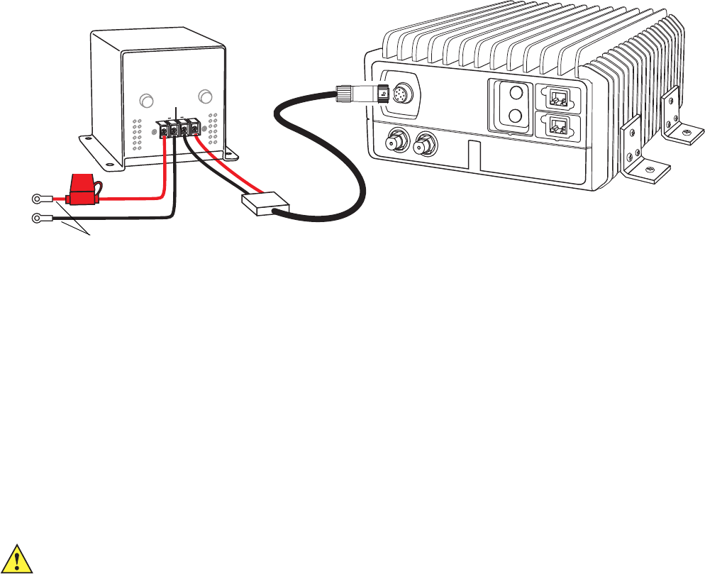
55
MN003563A01-B
Vehicle Installation
Send Feedback
The NAV-PAC has two available models: NP-12 NAV-PAC for 12 Volt vehicle and NP-24 NAV-PAC for 24
Volts vehicles.
Figure 3-6
Installing the Optional Power Protection and Back-up Unit
For detailed information on the LXN 500 installation, refer to the NAV-PAC INSTALLATION AND
OPERATION MANUAL provided with the NAV-PAC.
Installing the LXN 500
The LXN 500 should be mounted inside the vehicle so that cables coming from all peripheral devices
can be connected easily to the connectors on the back panel. The LXN 500 is designed to be mounted
on a flat surface in any position as long as the rear and front panels are accessible.
The LXN 500 is mounted by four mounting brackets (See Figure 3-7 and Figure 3-4). The mounting
brackets of the LXN 500 enable to mount the LXN 500 on a flat horizontal or vertical surface. The unit is
usually installed inside a trunk of a vehicle, or on tray or any fixed mounting board (See Figure 3-7).
IMPORTANT To prevent overheat damage to the LXN 500, the unit is designed to automatically shut down
above 60°C (149°F).
PWR
INPUT
OUTPUT
+ -+ -
+ -+ -
IMPORTANT Connect the red wire directly to the (+) terminal of the vehicle battery and the black wire to the chassis
of the vehicle.
20A Fuse
CAUTION When installed inside a vehicle trunk, be aware that ventilation of the trunk may be
necessary to keep the LXN 500 within ambient temperature limits of -4°F to 140°F (-20°C
to +60°C). If necessary, add fans to control the ambient temperature inside the trunk.
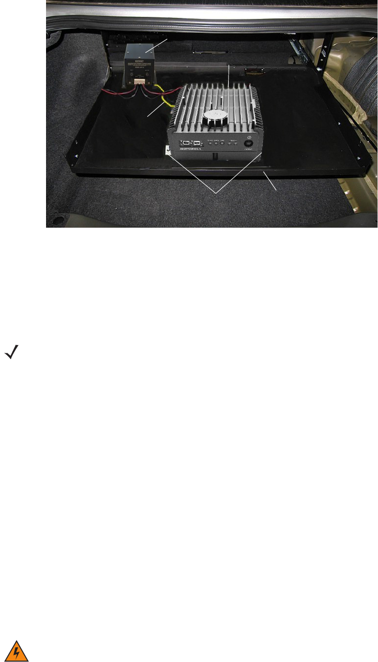
MN003563A01-B
Vehicle Installation
56 Send Feedback
Figure 3-7
LXN 500 Installed Inside a Trunk of a Vehicle
To install the LXN 500:
1. Connect the four brackets to the LXN 500 using the provided 4mm Allen screws. Torque the screws
to 60.7 inch-pounds (70 kg-cm).
2. Ground the LXN 500 to the vehicle chassis (See Ground Polarity on page 52).
3. Secure the LXN 500 to the mounting surface using four 1/4" self-drilling tap screws.
4. Connect the antenna cables to the connectors on the back panel of the LXN 500 (See Figure 3-1 and
Figure 3-2).
5. Connect the power cable to the PWR connector at the back panel of the LXN 500 (See Figure 3-4
and Figure 3-6).
IMPORTANT To avoid possible shout down of the LXN 500 during engine cranking, a Power Protection and
Backup unit should be used (See Installing the Optional Power Protection and Back-up Unit
on page 54).
Installing Antennas
Vehicle RF antennas must be installed in external to the vehicle and in accordance with:
•
Requirements of the antenna manufacturer/supplier.
•
Instructions provided by the installation manual of other radio devices installed next to the LXN
500.
Tray
LXN 500
Tray Lip
Mounting Brackets
Ground Connection Point
Optional Power Protection and Back-up Unit
NOTE The LXN 500 Mounting Bracket must be connected to the vehicle chassis through a low impedance
ground connection. Bolt the Mounting Bracket directly to the vehicle chassis or connect it to the vehicle
chassis by Ground wire or copper braided ground strap.
WARNING!To comply with safety regulations, the distance between antennas and people sitting inside the
vehicle must be more than 16 inches (40 cm).
When mounting antennas, the distance between antennas must be more than 16 inches (40 cm).

57
MN003563A01-B
Vehicle Installation
Send Feedback
Mounting Guide lines
Installation guidelines for antennas:
1. Use only antennas supplied with the LXN 500.
2. Use the installation instructions provided with the antenna by manufacturer/supplier.
3. If possible, the antenna location must not be obstructed by any structure or object. When installing
the antenna on a roof or a trunk lid, ensure clear space around the antenna.
4. Ensure that the installation surface is grounded by connecting grounding straps between the surface
and the vehicle chassis.
IMPORTANT To assure optimum performance and compliance with RF Energy Safety
standards, these antenna installation guidelines and instructions are limited to
metal-body vehicles with appropriate ground planes and take into account the
potential exposure of back seat passengers and bystanders outside the vehicle.
For detailed product safety and RF exposure, refer to Safety and General
Information leaflet, Motorola Solutions publication number: 6866537D37.
59
MN003563A01-B
Troubleshooting and Maintenance
Send Feedback
Troubleshooting and Maintenance
This chapter describes the maintenance operations available for the LXN 500 system.
Troubleshooting is the process of identifying the source of a fault. This process must be developed by
user to detect a fault as quickly as possible. This guide covers only the high-level troubleshooting
process performed by the LXN 500 users.
Troubleshooting should start from the least invasive and easy-to-do activities and progress to the more
difficult. The following provides a high-level sequence of troubleshooting escalation:
1. Reading LED indications:
The state of the LEDs (See Table 1-1 on page 1-12) is a result of the device’s power-on self test and
on-going operation. Reading the LEDs souled be done during operation. In most cases, restarting
the LXN 500 may resolve problems.
2. Performing PTT calls and data exchange between devices connected to the LXN 500 to test
communication.
3. Checking the mobile devices connected to the LXN 500 for proper operation, USIM installation and
4G (LTE) settings.
4. Performing point-to point communication diagnostics between the LXN 500 and a mobile device:
This step requires you to physically test communication at various points throughout the coverage
area using a diagnostic application running on one of the mobile devices connected to LXN 500 (See
Communication Diagnostics on page 33).
5. Running diagnostic on the LXN 500:
The LXN 500 has a built-in diagnostic option (See Performing Diagnostics on page 33). Using
Ethernet wire connection to a laptop and a web browser, the LXN 500 O&M Management can
display details about faulty sections of the LXN 500 and provide detailed log of activity.
6. Checking the configuration: This step requires you to have all relevant system information with you to
ensure that the LXN 500 is configured correctly. If your LXN 500 is configured as stated in this guide,
then you may have to verify that your configuration information is correct.
7. Contacting Motorola Solutions Customer Service for remote connection and troubleshooting of the
LXN 500.

MN003563A01-B
Troubleshooting and Maintenance
60 Send Feedback
Troubleshooting
Table 4-1
Troubleshooting
Problem/Indication Possible Cause Remedy
LXN 500 does not
power up
1. Power button not
pressed properly
2. Ambient temperature is
out of limits
3. Power cable not
connected properly
4. Power cable fuse is
blown
1. Press and hold the Power button until the LEDs on
the front panel start to illuminate (Powering On on
page 18).
2. Verify that the
LXN 500 is properly ventilated and
resume operation (See
Ventilation on page 51
)
3. Verify that the power cable is plunged and secured
to the PWR connector on the back panel
4. Replace the fuse of the power cable (See Figure
3-4)
10 minutes after
startup the CORE or
RADIO LED do not
show steady green
Internal synchronization
failed. (Core and Radio
synchronization failure)
Perform soft restart using the Power button (See Soft
Reseting using the Power Button on page 62)
Mobile device (UE)
unable to detect LXN
500
1. Internal Radio and/or
Core failure
2. LXN 500 antenna is
disconnected
3. Low strength of
transmitted signals
4. PLMN ID or LXN Unit ID
are incorrectly set
5. Subscriber device is out
of coverage area
1. Verify that the RADIO and CORE LEDs show
steady green. If not - soft reset the system (See
Soft Reseting using the Power Button on page 62).
If 10 minutes after reset LEDs does not show
steady green, contact support.
2. Verify that LTE1 and LTE2 antenna cables are
connected to the LXN 500 (SeeConfiguration
Options of Antenna Installation on page 48)
3. Verify that the LXN 500 power settings are
configured properly (See Setting the eNodeB on
page 30).
4. Verify that PLMN ID or LXN Unit ID are correctly set
in the LXN 500.
5. Try to change the location of the mobile device.
Move closer to LXN 500 and avoid places that
block radio waves like metal objects.
Also check:
•
In the mobile device, verify or set APN Name to
Internet and APN type to default
•
Verify the subscriber’s USIM is registered and
activated in the system (See
Deactivating/Activating Subscriber on page 25)

61
MN003563A01-B
Troubleshooting and Maintenance
Send Feedback
Mobile device unable
to connect to LXN 500
1. APN of LXN 500 is not
configured properly in
mobile device
2. USIM is not provisioned
or disabled in the LXN
500
1. In the mobile device, verify or set APN Name to
Internet and APN type to default
2. Verify the USIM of the mobile device is listed
correctly in the LXN 500 Adding a Single
Subscriber (UEs) on page 24
3. Soft reset the mobile device to re-connect (See Soft
Reseting using the Power Button on page 62)
Mobile device unable
to login to one of the
applications
(No PTT, messaging or
location services)
1. User is not defined in
the
WAVE 5000 or
Dragon Force
applications or incorrect
password
2. WAVE 5000 certificate
is missing in mobile
device
3. Certified APK version is
missing in mobile
device
4.
WAVE 5000 and/or
Dragon Force
application is not
enabled in LXN 500
1. Verify that User Names and Passwords are defined
in the mobile device for the
WAVE 5000 and/or
Dragon Force
applications
2. Install WAVE 5000 certificate on mobile device
3. Install certified APK version
4. Verify that
WAVE 5000 or Dragon Force are installed
and can be accessed
(See Configuring the
DragonForce Server on page 43 and Configuring
the WAVE 5000 Server on page 44)
After modifying the
EARFCN in the LXN
500, mobile devices
cannot detect and
connect to the LXN
500.
1. The mobile device fails
to detect the LXN 500.
1. In the mobile device, perform a search for cellular
networks - the required network will not be shown.
2. Restart the mobile device - after the restart, the
phone should connect automatically. If not the
mobile device does not connect automatically,
search for cellular networks and select the APN
name of the LXN 500.
Table 4-1
Troubleshooting (Continued)
Problem/Indication Possible Cause Remedy

MN003563A01-B
Troubleshooting and Maintenance
62 Send Feedback
Software Update
The LXN 500 supports easy software update via a flash drive connected to a USB port. Verify that the
used flash drive is formatted with FAT32 file system.
Perform this procedure to update the LXN 500 software:
1. Contact Motorola Solution support and download the LXN 500 software update file.
2. Copy the update file to:\Update folder on USB flash drive.
3. Power on the LXN 500 and wait until all LEDs show steady green (See Powering On on page 18).
4. Remove the protective cover and insert the flash drive into one of the USB ports on the front panel of
the LXN 500.
Result: Once the flash drive is inserted, the LXN 500 automatically starts the software update
process and the front panel LEDs illuminate orange in a repeated sequence.
5. Wait until all LEDS show steady green and remove the USB flash drive. Install the protective cover
on the USB port.
Resetting the LXN 500
Soft Reseting using the Power Button
Soft reset is a restarting of the LXN 500 such as a personal computer (PC). The action closes all
applications and clears any data. Applications and settings are not affected.
Perform this procedure to soft reset the LXN 500 using the Power button.
Procedure:
1. Press and hold the Power button for four seconds.
Result: all LEDs on the front panel blink orange, to indicate power down, and than turn off.
2. Press and hold the Power button for four seconds and release when all LEDs begin to flash
green. Wait the until all LEDs are steady green.
Soft Resetting via O&M
This operation re-boots the LXN 500 the same as soft reseting using the Power button.
Perform this procedure to reset the LXN 500 from the O&M.
Procedure:
1. Sign in to the LXN 500 O&M Configuration site (See Signing In on page 20).
2. Click on and select Reset the LXN 500.
Result: The LXN 500 re-boots.
Hard Resetting
Hard reset is required when the LXN 500 stops to respond and soft reset does not work. Hard reset
immediately removes power from the LXN 500 and restarting the computer is required.

63
MN003563A01-B
Troubleshooting and Maintenance
Send Feedback
Perform this procedure to hard reset the LXN 500.
Procedure:
1. Press and hold the Power button for more than 15 seconds.
Result: all LEDs on the front panel turn off.
2. Press and hold the Power button for four seconds and release when all LEDs begin to flash
green. Wait until the LEDs are steady green.
Resetting the eNodeB
Use the Reset the eNodeB option when performing configuration and the LXN 500 fails to operate (one
or more RADIO LED illuminate orange or red).
Perform this procedure to reset the LXN 500.
Procedure:
1. Sign in to the LXN 500 O&M Configuration site (See Signing In on page 20).
Click on and select Reset the eNodeB.
Result: The eNode re-boots and RADIO LED illuminates green.

65
MN003563A01-B
Technical Specifications
Send Feedback
Technical Specifications
4G LTE
Release 3GPP Release 10
Band Class • 4G (LTE) Band 14
•4G (LTE) Band 20
•4G (LTE) Band 28b
Single band supported per each LXN 500
Bandwidth: 5 MHz, 10 MHz, 20 Mhz
Output Power 30 dBm effective radiated power (ERP) 2W MIMO
Bandwidth 5 MHz, 10 MHz, 20 Mhz
CONNECTIVITY
Wi-Fi Connectivity 802.11b/g 2.4 GHz for units with LTE B20 and B28b radio
802.11b/g 2.4 GHz for unit with LTE B14 radio
Device can act as access point or client
Up to 6 Wi-Fi devices
164 ft (50 m) line-of-sight
Wired Connectivity 2 Ethernet ports
(1Gbit/s, RJ-45)
2 USB 2.0 port
WLAN Security WPA, WPA 2, WPA-PSK and WPA-EAP
GPS Autonomous GPS, 1 external antenna
Supports NMEA, TAIP-PV
ENVIRONMENTAL
Operating Temperature Vehicle Configuration -22°F to 140°F (-20°C to 60°C)
Backpack Configuration -22°F to 131°F (-20°C to 55°C) (Future option of the LXN 500)
Storage Temperature -40°F to 185°F (-40°C to 85°C)
MANAGEMENT AND SUPPORT
Field-upgradable Via USB/WiFi/Ethernet
Regulatory CE and FCC
STANDARDS
Durability IP54
PHYSICAL CHARACTERISTICS
Dimensions Height: 4.6 in (119 mm)
Width: 9.2 in (231 mm)
Length: 11.6 in (295 mm)
Weight 12.67 lb (5.75 kg)
