Motorola Solutions 99FT3088 VHF Portable Radio User Manual LKP NAG LACR
Motorola Solutions, Inc. VHF Portable Radio LKP NAG LACR
Contents
- 1. User Manual/Guide
- 2. Safety Manual
User Manual/Guide
M
MOTOTRBO XPRTM 3500/3550
Limited Keypad Portable
User Guide
68009512001-A
LKP_NAG-LACR.book Page i Tuesday, September 6, 2011 5:01 PM
LKP_NAG-LACR.book Page ii Tuesday, September 6, 2011 5:01 PM
Declaration of Conformity
English
i
Declaration of Conformity
This declaration is applicable to your radio only if your radio is labeled with the FCC logo shown below.
DECLARATION OF CONFORMITY
Per FCC CFR 47 Part 2 Section 2.1077(a)
Responsible Party
Name: Motorola Solutions, Inc.
Address: 1301 East Algonquin Road, Schaumburg, IL 60196-1078, U.S.A.
Phone Number: 1-800-927-2744
Hereby declares that the product:
Model Name: XPR 3300/3350
conforms to the following regulations:
FCC Part 15, subpart B, section 15.107(a), 15.107(d) and section 15.109(a)
Class B Digital Device
As a personal computer peripheral, this device complies with Part 15 of the FCC Rules. Operation is subject to the
following two conditions:
1. This device may not cause harmful interference, and
2. This device must accept any interference received, including interference that may cause undesired operation.
LKP_NAG-LACR.book Page i Tuesday, September 6, 2011 5:01 PM

Declaration of Conformity
English
ii
Note:This equipment has been tested and found to comply with the limits for a Class B digital device, pursuant to part
15 of the FCC Rules. These limits are designed to provide reasonable protection against harmful interference in a
residential installation. This equipment generates, uses and can radiate radio frequency energy and, if not
installed and used in accordance with the instructions, may cause harmful interference to radio communications.
However, there is no guarantee that interference will not occur in a particular installation.
If this equipment does cause harmful interference to radio or television reception, which can be determined by
turning the equipment off and on, the user is encouraged to try to correct the interference by one or more of the
following measures:
• Reorient or relocate the receiving antenna.
• Increase the separation between the equipment and receiver.
• Connect the equipment into an outlet on a circuit different from that to which the receiver is connected.
• Consult the dealer or an experienced radio/TV technician for help.
LKP_NAG-LACR.book Page ii Tuesday, September 6, 2011 5:01 PM

English
1
Contents
This User Guide contains all information you need to use the
MOTOTRBO XPR 3500/3550 Digital Portable Radios.
Declaration of Conformity . . . . . . . . . . . . . . . . . . . . . i
Important Safety Information . . . . . . . . . . . . . . . . . . 5
Product Safety and RF Exposure Compliance . . . 5
Firmware Version . . . . . . . . . . . . . . . . . . . . . . . . . . . . 5
Computer Software Copyrights . . . . . . . . . . . . . . . . 6
Handling Precautions . . . . . . . . . . . . . . . . . . . . . . . . 7
Notes . . . . . . . . . . . . . . . . . . . . . . . . . . . . . . . . . . . . . . 8
How to Use This Guide . . . . . . . . . . . . . . . . . . . . . . . 1
What Your Dealer/System Administrator
Can Tell You . . . . . . . . . . . . . . . . . . . . . . . . . . . . . . 1
Charging the Battery . . . . . . . . . . . . . . . . . . . . . . . . . 2
Attaching the Battery . . . . . . . . . . . . . . . . . . . . . . . . . 2
Attaching the Antenna . . . . . . . . . . . . . . . . . . . . . . . . 3
Attaching the Belt Clip . . . . . . . . . . . . . . . . . . . . . . . . 3
Attaching the Universal Connector Cover (Dust Cover)
4
Attaching the Accessory Connector . . . . . . . . . . . . . 4
Powering Up the Radio . . . . . . . . . . . . . . . . . . . . . . . 5
Adjusting the Volume . . . . . . . . . . . . . . . . . . . . . . . . 6
Radio Controls . . . . . . . . . . . . . . . . . . . . . . . . . . . . . 6
Programmable Buttons . . . . . . . . . . . . . . . . . . . . . . . 7
Assignable Radio Functions . . . . . . . . . . . . . . . . . 8
Assignable Settings or Utility Functions . . . . . . . . . 9
Accessing the Programmed Functions . . . . . . . . . . . 9
Push-To-Talk (PTT) Button . . . . . . . . . . . . . . . . . . . 10
Switching Between Conventional Analog and Digital
Mode . . . . . . . . . . . . . . . . . . . . . . . . . . . . . . . . . . . 11
Capacity Plus . . . . . . . . . . . . . . . . . . . . . . . . . . . . . 11
Display Icons . . . . . . . . . . . . . . . . . . . . . . . . . . . . . . 12
Call Icons . . . . . . . . . . . . . . . . . . . . . . . . . . . . . . . . 13
Advanced Menu Icons . . . . . . . . . . . . . . . . . . . . . . 13
Mini Notice Icons . . . . . . . . . . . . . . . . . . . . . . . . . . 14
LED Indicator . . . . . . . . . . . . . . . . . . . . . . . . . . . . . 14
Audio Tones . . . . . . . . . . . . . . . . . . . . . . . . . . . . . . 15
Indicator Tones . . . . . . . . . . . . . . . . . . . . . . . . . . . . 16
Making and Receiving Calls . . . . . . . . . . . . . . . . . . 16
Selecting a Site . . . . . . . . . . . . . . . . . . . . . . . . . . . 16
Selecting a Zone . . . . . . . . . . . . . . . . . . . . . . . . . . . 17
Selecting a Radio Channel, Subscriber ID,
or Group ID . . . . . . . . . . . . . . . . . . . . . . . . . . . . . . 17
Receiving and Responding to a Radio Call . . . . . . 18
Receiving and Responding to a Group Call . . . . . 18
Receiving and Responding to a Private Call . . . 19
Receiving an All Call . . . . . . . . . . . . . . . . . . . . . . 20
LKP_NAG-LACR.book Page 1 Tuesday, September 6, 2011 5:01 PM

English
2
Receiving and Responding to a Selective Call . 21
Making a Radio Call . . . . . . . . . . . . . . . . . . . . . . . . 22
Making a Call with the Channel Selector Knob . . 22
Making a Selective Call . . . . . . . . . . . . . . . . . . . 24
Making a Call with the One Touch Access
Button . . . . . . . . . . . . . . . . . . . . . . . . . . . . . . . . . 25
Stopping a Radio Call . . . . . . . . . . . . . . . . . . . . . . 26
Talkaround . . . . . . . . . . . . . . . . . . . . . . . . . . . . . . . 26
Monitoring Features . . . . . . . . . . . . . . . . . . . . . . . . 27
Monitoring a Channel . . . . . . . . . . . . . . . . . . . . . 27
Permanent Monitor . . . . . . . . . . . . . . . . . . . . . . . 27
Radio Check . . . . . . . . . . . . . . . . . . . . . . . . . . . . . 28
Sending a Radio Check . . . . . . . . . . . . . . . . . . . 28
Scan Lists . . . . . . . . . . . . . . . . . . . . . . . . . . . . . . . . 29
Viewing an Entry in the Scan List . . . . . . . . . . . . 29
Editing the Scan List . . . . . . . . . . . . . . . . . . . . . . 30
Scan . . . . . . . . . . . . . . . . . . . . . . . . . . . . . . . . . . . . 31
Starting and Stopping Scan . . . . . . . . . . . . . . . . 32
Responding to a Transmission During a Scan . . 32
Deleting a Nuisance Channel . . . . . . . . . . . . . . . 33
Restoring a Nuisance Channel . . . . . . . . . . . . . . 33
Vote Scan . . . . . . . . . . . . . . . . . . . . . . . . . . . . . . . . 34
Contacts Settings . . . . . . . . . . . . . . . . . . . . . . . . . . 34
Making a Group Call from Contacts . . . . . . . . . . 35
Making a Private Call from Contacts . . . . . . . . . 36
Setting Default Contact . . . . . . . . . . . . . . . . . . . 36
Call Indicator Settings . . . . . . . . . . . . . . . . . . . . . . 37
Activating and Deactivating Call Ringers for Call Alert
37
Activating and Deactivating Call Ringers for Private
Calls . . . . . . . . . . . . . . . . . . . . . . . . . . . . . . . . . . 37
Activating and Deactivating Call Ringers for Selective
Call . . . . . . . . . . . . . . . . . . . . . . . . . . . . . . . . . . . 38
Activating and Deactivating Call Ringers for Text
Message . . . . . . . . . . . . . . . . . . . . . . . . . . . . . . 38
Assigning Ring Styles . . . . . . . . . . . . . . . . . . . . 39
Escalating Alarm Tone Volume . . . . . . . . . . . . . . 39
Call Log Features . . . . . . . . . . . . . . . . . . . . . . . . . 40
Viewing Recent Calls . . . . . . . . . . . . . . . . . . . . . 40
Deleting a Call from a Call List . . . . . . . . . . . . . . 40
Call Alert Operation . . . . . . . . . . . . . . . . . . . . . . . . 41
Receiving and Responding to a Call Alert . . . . . 41
Making a Call Alert from the Contacts List . . . . . 42
Making a Call Alert with the One Touch Access Button
42
Emergency Operation . . . . . . . . . . . . . . . . . . . . . . 43
Sending an Emergency Alarm . . . . . . . . . . . . . . 44
Sending an Emergency Alarm with Call . . . . . . . 44
Sending an Emergency Alarm with Voice to
Follow . . . . . . . . . . . . . . . . . . . . . . . . . . . . . . . . . 45
Reinitiating an Emergency Mode . . . . . . . . . . . . 46
LKP_NAG-LACR.book Page 2 Tuesday, September 6, 2011 5:01 PM

English
3
Exiting Emergency Mode . . . . . . . . . . . . . . . . . . . 46
Analog Message Encode . . . . . . . . . . . . . . . . . . . 49
Sending MDC Message Encode to Dispatcher . . 49
Analog Status Update . . . . . . . . . . . . . . . . . . . . . . 49
Sending Status Update to Predefined Contact . . 49
Privacy . . . . . . . . . . . . . . . . . . . . . . . . . . . . . . . . . . 50
Dual Tone Multi Frequency (DTMF) . . . . . . . . . . . . 51
IP Site Connect . . . . . . . . . . . . . . . . . . . . . . . . . . . 51
Starting an Automatic Site Search . . . . . . . . . . . . 52
Stopping an Automatic Site Search . . . . . . . . . . . 53
Starting a Manual Site Search . . . . . . . . . . . . . . . 53
Security . . . . . . . . . . . . . . . . . . . . . . . . . . . . . . . . . 54
Radio Disable . . . . . . . . . . . . . . . . . . . . . . . . . . . 54
Radio Enable . . . . . . . . . . . . . . . . . . . . . . . . . . . . 55
Lone Worker . . . . . . . . . . . . . . . . . . . . . . . . . . . . . . 56
Password Lock Features . . . . . . . . . . . . . . . . . . . . 57
Accessing the Radio from Password . . . . . . . . . . 57
Unlocking the Radio from Locked State . . . . . . . 57
Turning the Password Lock On or Off . . . . . . . . . 58
Changing the Password . . . . . . . . . . . . . . . . . . . . 58
Notification List . . . . . . . . . . . . . . . . . . . . . . . . . . . . 59
Accessing the Notification List . . . . . . . . . . . . . . . 59
Utilities . . . . . . . . . . . . . . . . . . . . . . . . . . . . . . . . . . 60
Turning the Radio Tones/Alerts On or Off . . . . . . 60
Setting the Tone Alert Volume Offset Level . . . . 60
Turning the Talk Permit Tone On or Off . . . . . . . 61
Setting the Power Level . . . . . . . . . . . . . . . . . . . . 61
Adjusting the Display Brightness . . . . . . . . . . . . . 62
Controlling the Display Backlight . . . . . . . . . . . . . 62
Setting the Squelch Level . . . . . . . . . . . . . . . . . . 63
Turning the Introduction Screen On or Off . . . . . . 63
. . . . . . . . . . . . . . . . . . . . . . . . . . . . . . . . . . . . . . . 63
Language . . . . . . . . . . . . . . . . . . . . . . . . . . . . . . . 64
Turning the LED Indicator On or Off . . . . . . . . . . 64
Turning the Voice Operating Transmission (VOX)
Feature On or Off . . . . . . . . . . . . . . . . . . . . . . . . . 64
Voice Announcement . . . . . . . . . . . . . . . . . . . . . . 65
Call Forwarding . . . . . . . . . . . . . . . . . . . . . . . . . . 66
Menu Timer . . . . . . . . . . . . . . . . . . . . . . . . . . . . . 67
Analog Mic AGC . . . . . . . . . . . . . . . . . . . . . . . . . 67
Digital Mic AGC . . . . . . . . . . . . . . . . . . . . . . . . . . 68
Intelligent Audio . . . . . . . . . . . . . . . . . . . . . . . . . . 68
Accessing General Radio Information . . . . . . . . . 69
Front Panel Configuration (FPC) . . . . . . . . . . . . . . 70
Entering FPC Mode . . . . . . . . . . . . . . . . . . . . . . . 70
Editing FPC Mode Parameters . . . . . . . . . . . . . . 70
Accessories . . . . . . . . . . . . . . . . . . . . . . . . . . . . . . . 71
Antennas . . . . . . . . . . . . . . . . . . . . . . . . . . . . . . . . . 71
Batteries . . . . . . . . . . . . . . . . . . . . . . . . . . . . . . . . . 71
Cables . . . . . . . . . . . . . . . . . . . . . . . . . . . . . . . . . . 72
LKP_NAG-LACR.book Page 3 Tuesday, September 6, 2011 5:01 PM

English
4
Carry Devices . . . . . . . . . . . . . . . . . . . . . . . . . . . . . 72
Chargers . . . . . . . . . . . . . . . . . . . . . . . . . . . . . . . . . 72
Earbuds and Earpieces . . . . . . . . . . . . . . . . . . . . . 73
Headsets and Headset Accessories . . . . . . . . . . . 73
Remote Speaker Microphones . . . . . . . . . . . . . . . . 73
Surveillance Accessories . . . . . . . . . . . . . . . . . . . . 73
Miscellaneous Accessories . . . . . . . . . . . . . . . . . . 74
Batteries and Chargers Warranty . . . . . . . . . . . . . 75
Limited Warranty . . . . . . . . . . . . . . . . . . . . . . . . . . . 76
LKP_NAG-LACR.book Page 4 Tuesday, September 6, 2011 5:01 PM

Important Safety Information
English
5
Important Safety Information
Product Safety and RF Exposure Compliance
ATTENTION!
This radio is restricted to occupational use only to
satisfy FCC RF energy exposure requirements.
Before using this product, read the RF energy awareness
information and operating instructions in the Product
Safety and RF Exposure booklet enclosed with your radio
(Motorola Publication part number 6881095C98) to
ensure compliance with RF energy exposure limits.
For a list of Motorola-approved antennas, batteries, and
other accessories, visit the following website:
http://www.motorolasolutions.com/governmentandenterprise
Firmware Version
All the features described in the following sections are
supported by the radio's software version R02.00.00.
See Checking the Firmware Version and Codeplug
Version and Codeplug Version on page 70 to
determine your radio's software version.
Check with your dealer or system administrator
for more details of all the features supported.
Before using this product, read the operating
instructions for safe usage contained in the
Product Safety and RF Exposure booklet
enclosed with your radio.
LKP_NAG-LACR.book Page 5 Tuesday, September 6, 2011 5:01 PM

Computer Software Copyrights
English
6
Computer Software Copyrights
The Motorola products described in this manual may
include copyrighted Motorola computer programs stored
in semiconductor memories or other media. Laws in the
United States and other countries preserve for Motorola
certain exclusive rights for copyrighted computer
programs including, but not limited to, the exclusive right
to copy or reproduce in any form the copyrighted
computer program. Accordingly, any copyrighted
Motorola computer programs contained in the Motorola
products described in this manual may not be copied,
reproduced, modified, reverse-engineered, or distributed
in any manner without the express written permission of
Motorola. Furthermore, the purchase of Motorola
products shall not be deemed to grant either directly or by
implication, estoppel, or otherwise, any license under the
copyrights, patents or patent applications of Motorola,
except for the normal non-exclusive license to use that
arises by operation of law in the sale of a product.
The AMBE+2TM voice coding Technology embodied in
this product is protected by intellectual property rights
including patent rights, copyrights and trade secrets of
Digital Voice Systems, Inc.
This voice coding Technology is licensed solely for use
within this Communications Equipment. The user of this
Technology is explicitly prohibited from attempting to
decompile, reverse engineer, or disassemble the Object
Code, or in any other way convert the Object Code into a
human-readable form.
U.S. Pat. Nos. #5,870,405, #5,826,222, #5,754,974,
#5,701,390, #5,715,365, #5,649,050, #5,630,011,
#5,581,656, #5,517,511, #5,491,772, #5,247,579,
#5,226,084 and #5,195,166.
LKP_NAG-LACR.book Page 6 Tuesday, September 6, 2011 5:01 PM
Handling Precautions
English
7
Handling Precautions
The Andorra Portables radio meets IP55 specifications with
antenna attached, allowing the radio to withstand adverse field
conditions such as being used in rain or dusty environment.
•If the radio has been exposed to water or rain, shake the
radio well to remove any water that may be trapped inside the
speaker grille, microphone port and aesthetic cover(if
applicable). Trapped water in speaker grille and microphone
port could cause decreased audio performance. If aesthetic
cover is attached onto radio, trapped water in aesthetic cover
could cause corrosion on the slim connector interface gold
contacts.
•If the radio’s battery contact area has been exposed to water,
clean and dry battery contacts on both the radio and the
battery before attaching the battery to the radio. The residual
water could short-circuit the radio.
•If the radio has been exposed to corrosive substance
(e.g.saltwater), rinse the radio and battery in fresh water then
dry the radio and battery.
•To clean the exterior surfaces of the radio, use a diluted
solution of mild dishwashing detergent and fresh water (i.e.
one teaspoon of detergent to one gallon of water).
•The radio with antenna attached properly is designed to be
protected against dust and low pressure jets of water
projected with nozzle 6.3mm diameter at flow rate of 12.5 l/
min, with water pressure at 30 kN/m2 and from a distance of
2.5m to 3m for at least 3 min. Exceeding either maximum limit
or use without antenna may result in damage to the radio.
•When cleaning the radio, do not use a high pressure jet spray
on the radio as this may cause to leak.
Do not disassemble the radio. This could
damage radio seals and result in leak paths into
the radio. Radio maintenance should only be
done in service depot that is equipped to test
and replace the seal on the radio.
LKP_NAG-LACR.book Page 7 Tuesday, September 6, 2011 5:01 PM

Notes
English
8
Notes
LKP_NAG-LACR.book Page 8 Tuesday, September 6, 2011 5:01 PM

English
1
How to Use This Guide
This User Guide covers the basic operation of the MOTOTRBO
Portables.
However, your dealer or system administrator may have
customized your radio for your specific needs. Check with your
dealer or system administrator for more information.
Throughout this publication, the icons below are used to
indicate features supported in either the conventional Analog
mode or conventional Digital mode:
For features that are available in both conventional Analog and
Digital modes, no icon is shown.
Selected features are also available on the single-site trunking
mode, Capacity Plus. See Capacity Plus on page 11 for more
information.
What Your Dealer/System Administrator
Can Tell You
You can consult your dealer or system administrator about the
following:
•Is your radio programmed with any preset conventional
channels?
•Which buttons have been programmed to access other
features?
•What optional accessories may suit your needs?
NOTE:
Indicates a conventional Analog Mode-Only feature.
Indicates a conventional Digital Mode-Only feature.
LKP_NAG-LACR.book Page 1 Tuesday, September 6, 2011 5:01 PM
English
2
Charging the Battery
Your radio is powered by a Nickel Metal-Hydride (NiMH) or
Lithium-Ion (Li-lon) battery. To avoid damage and comply with
warranty terms, charge the battery using a Motorola charger
exactly as described in the charger user guide.
Charge a new battery 14 to 16 hours before initial use for best
performance.
IMPORTANT:ALWAYS charge your IMPRES battery with an
IMPRES charger for optimized battery life and
valuable battery data. IMPRES batteries
charged exclusively with IMPRES chargers
receive a 6-month capacity warranty extension
over the standard Motorola Premium battery
warranty duration.
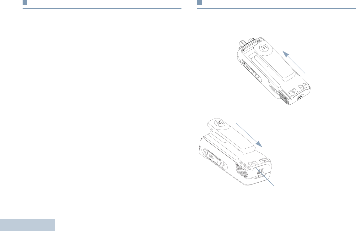
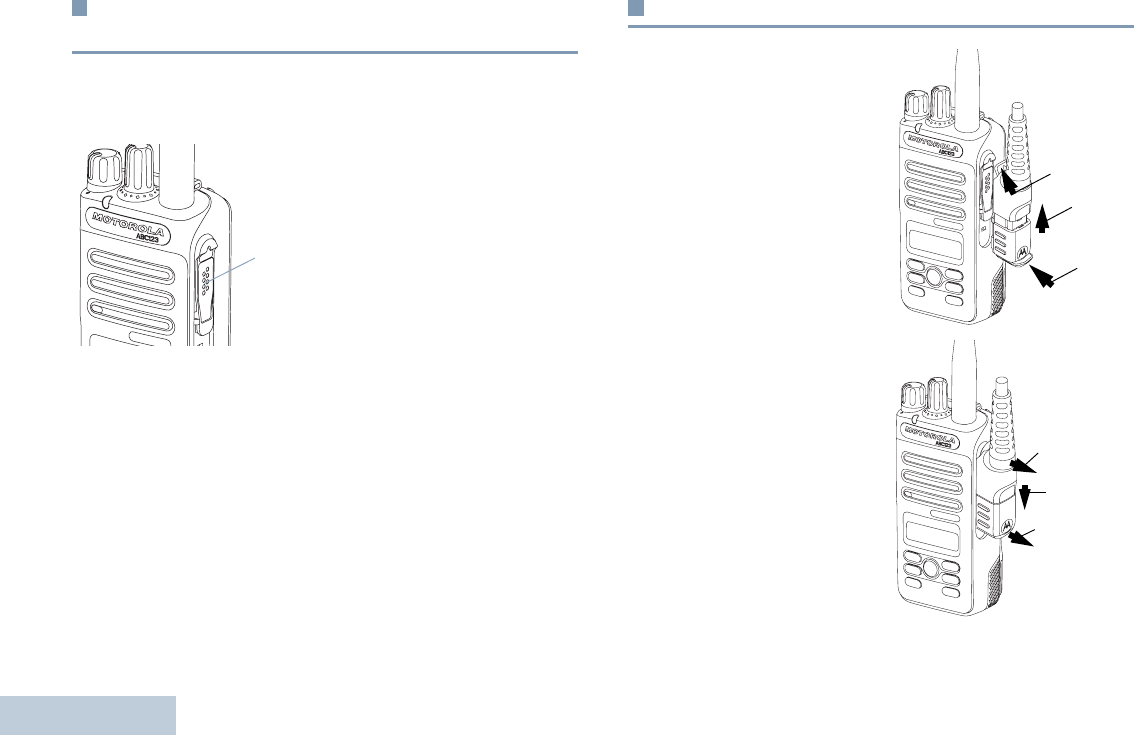
Attaching the Battery
Align the battery with the rails on the back of the radio. Press
the battery firmly, and slide upward until the latch snaps into
place. Slide battery latch into lock position.
To remove the battery,
turn the radio off. Move
the battery latch into
unlock position and
hold, and slide the
battery down and off
the rails.
Battery Latch
LKP_NAG-LACR.book Page 2 Tuesday, September 6, 2011 5:01 PM
English
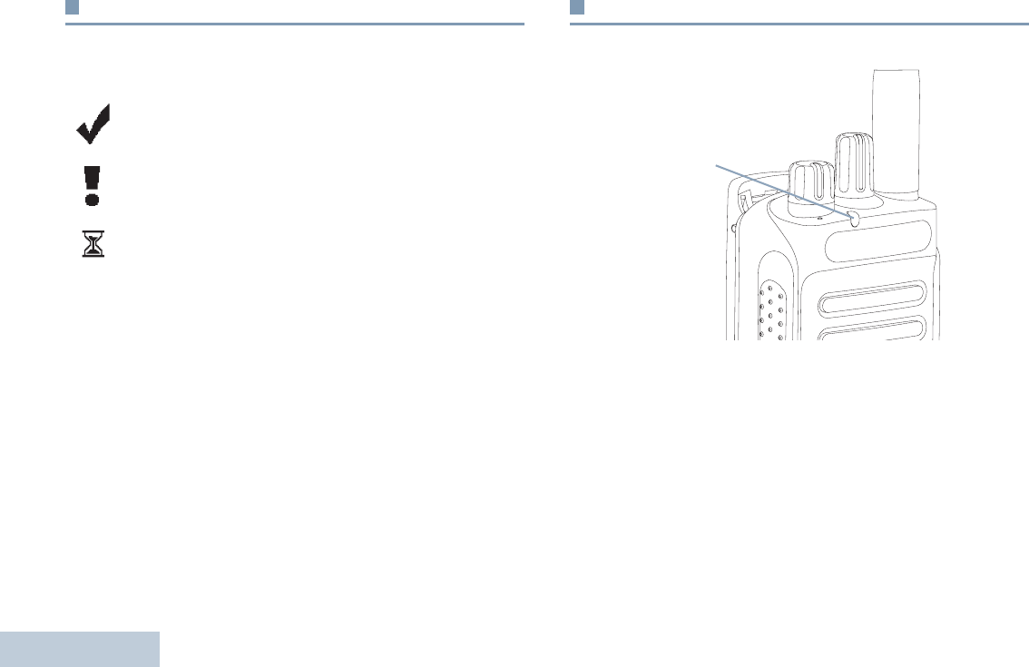
3
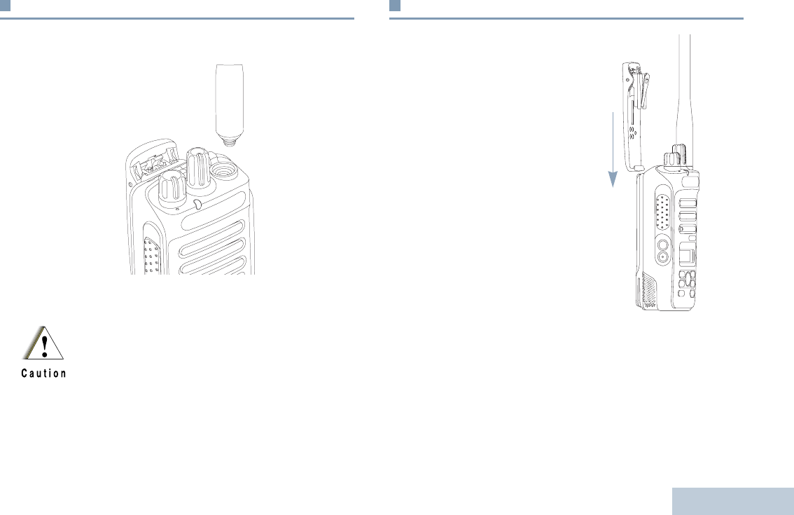
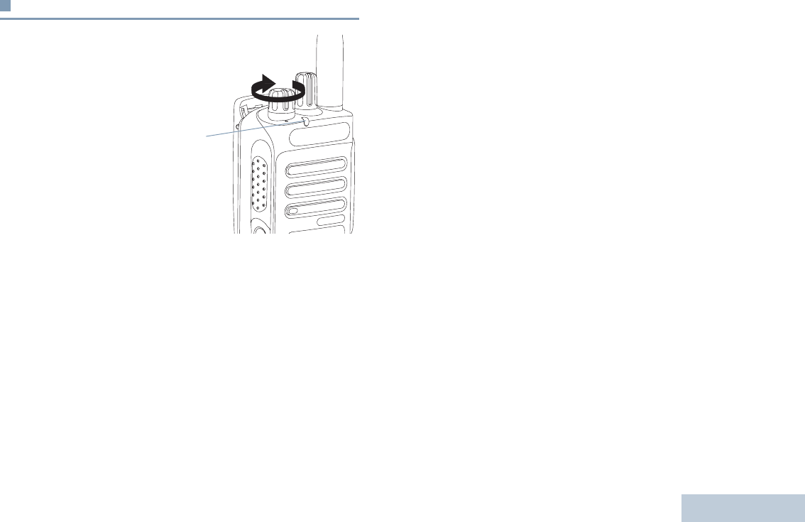
Attaching the Antenna
With the radio turned off, set the antenna in its receptacle and
turn clockwise.
To remove the antenna, turn the antenna counterclockwise.
Attaching the Belt Clip
Align the grooves on the clip
with those on the battery and
press downward until you hear
a click.
To remove the clip, press the
belt clip tab away from the
battery using a key. Then slide
the clip upward and away from
the radio.
If antenna needs to be replaced, ensure that only
MOTOTRBO antennas are used. Neglecting this will
damage your radio. See Antennas on page 71 for a list
of available antennas.
LKP_NAG-LACR.book Page 3 Tuesday, September 6, 2011 5:01 PM
English
4
Attaching the Universal Connector Cover
(Dust Cover)
The universal connector is located on the antenna side of the
radio. It is used to connect MOTOTRBO accessories to the
radio.
Insert the hooked end of the
cover into the slots above
the universal connector.
Press downward on the
cover to seat the lower tab
properly into the RF
connector.
Turn the thumbscrew
clockwise to secure the
connector cover to the radio.
To remove the universal connector cover, press down on the
cover and turn the thumbscrew counterclockwise. Lift the cover
up, slide the connector cover loop upwards, and remove it from
the attached antenna.
Replace the dust cover when the universal connector is not in
use.
Attaching the Accessory Connector
The accessory connector is
to be secured to the
universal connector on the
antenna side of the radio.
To attach the accessory
connector, refer to the steps
shown in the diagram.
To remove the accessory
connector, refer to the steps
shown in the diagram.
Universal
Connector
1
2
3
1
2
3
LKP_NAG-LACR.book Page 4 Tuesday, September 6, 2011 5:01 PM
English
5
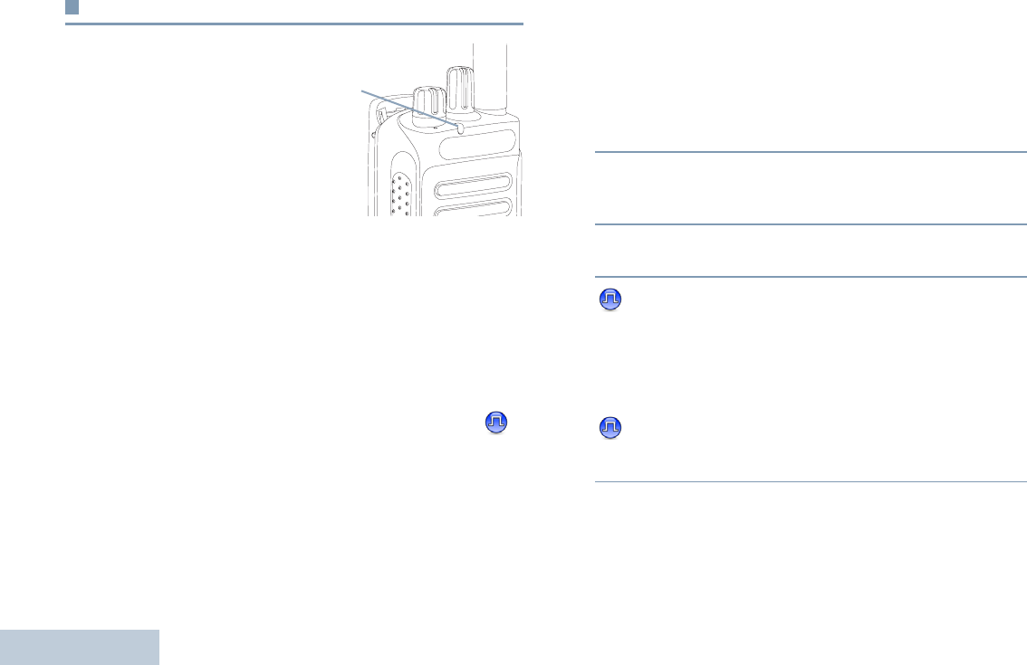
Powering Up the Radio
Rotate the On/Off/Volume
Control Knob clockwise
until you hear a click. You
see MOTOTRBO (TM) on the
radio’s display momentarily,
followed by a welcome
message.
The LED lights up solid
green and the Home screen
lights up if the backlight
setting is set to turn on
automatically.
NOTE: The Home screen does not light up during a power
up if the LED indicator is disabled (see Turning the
LED Indicator On or Off on page 64 ).
A brief tone sounds, indicating that the power up test is
successful.
NOTE: There is no power up tone if the radio tones/alerts
function is disabled (see Turning the Radio Tones/
Alerts On or Off on page 60).
If your radio does not power up, check your battery. Make sure
that it is charged and properly attached. If your radio still does
not power up, contact your dealer.
To turn off the radio, rotate this knob counterclockwise until you
hear a click. You see a brief
Powering Down
on the radio’s
display.
LED
Indicator
LKP_NAG-LACR.book Page 5 Tuesday, September 6, 2011 5:01 PM
English
6
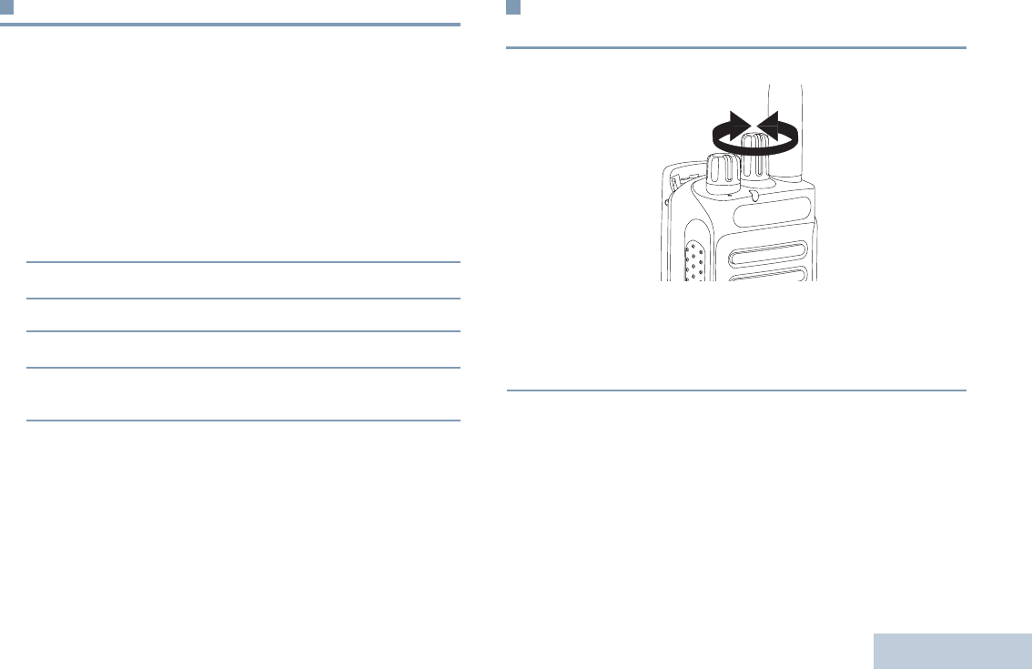
Adjusting the Volume
To increase the volume,
turn the On/Off/Volume
Control Knob clockwise.
To decrease the volume,
turn this knob
counterclockwise.
NOTE: Your radio can be
programmed to
have a minimum
volume offset
where the volume
level cannot be
turned down
fully. Check with
your dealer or
system
administrator for
more
information.
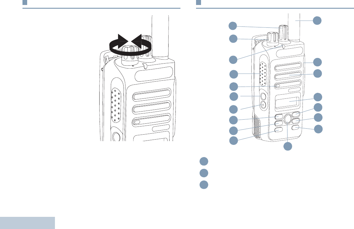
Radio Controls
Channel Selector Knob
On/Off/Volume Control Knob
LED Indicator
11
3
14
13
12
8
7
6
5
2
1
9
4
10
15
16
17
18
1
2
3
LKP_NAG-LACR.book Page 6 Tuesday, September 6, 2011 5:01 PM

English
7
Programmable Buttons
Your dealer can program the programmable buttons as
shortcuts to radio functions or preset channels/groups
depending on the duration of a button press:
•Short press – Pressing and releasing rapidly.
•Long press – Pressing and holding for the programmed
duration.
•Hold down – Keeping the button pressed.
NOTE: The programmed duration of a button press is
applicable for all assignable radio/utility functions
or settings. See Emergency Operation on page 43
for more information on the programmed duration
of the Emergency button.
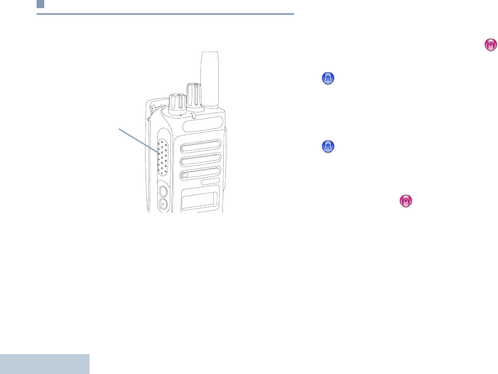
Push-to-Talk (PTT) Button
Microphone
Side Button 1*
Side Button 2*
Left Navigation Button
Menu Button
Front Button P1*
OK Button
Front Button P2*
Back/Home Button
Right Navigation Button
Display
Speaker
Universal Connector for Accessories
Antenna
* These buttons are programmable.
4
5
6
7
8
9
10
11
12
13
14
15
16
17
18
LKP_NAG-LACR.book Page 7 Tuesday, September 6, 2011 5:01 PM

English
8
Assignable Radio Functions
Contacts – Provides direct access to the Contacts list.
Call Alert – Direct acces to the radio contacts list to select
aradio contact to send a call alert to.
Call Forwarding – Toggles Call Forwarding on or off.
Call Log – Selects the call log list.
Channel Announcment – Plays zone and channel
announcement voice messages for the current channel.
Emergency – Depending on the programming, initiates or
cancels an emergency alarm or call.
Intelligent Audio On/Off – Toggles intelligent Audio on or off.
Manual Site Roam* – Starts the manual site search.
Mic AGC On/Off – Toggles the internal microphone automatic
gain control (AGC) on or off.
Monitor – Monitors a selected channel for activity.
Nuisance Channel Delete* – Temporarily removes an
unwanted channel, except for the Selected Channel, from the
scan list. The Selected Channel refers to the user’s selected
zone/channel combination from which scan is initiated.
One Touch Access – Directly initiates a predefined
Private or Group Call, a Call Alert or a Quick Text message.
Permanent Monitor* – Monitors a selected channel for all radio
traffic until function is disabled.
Privacy – Toggles privacy on or off.
Radio Alias and ID – Provides radio alias and ID.
Radio Check – Determines if a radio is active in a system.
Radio Enable – Allows a target radio to be remotely
enabled.
Radio Disable – Allows a target radio to be remotely
disabled.
Repeater/Talkaround* – Toggles between using a repeater
and communicating directly with another radio.
Scan* – Toggles scan on or off.
Site Lock On/Off* – Toggles the automatic site roam on or
off.
Transmit Interrupt Remote Dekey – Stops the
transmission of a remote monitored radio without giving any
indicators, or an ongoing interruptible call to free the channel.
Text Message – Selects the text message menu.
Voice Announcement On/Off – Toggles Voice Announcement
on or off.
* Not applicable in Capacity Plus
LKP_NAG-LACR.book Page 8 Tuesday, September 6, 2011 5:01 PM

English
9
Voice Operating Transmission (VOX) – Toggles VOX on or
off.
Zone – Allows selection from a list of zones.
Assignable Settings or Utility Functions
All Tones/Alerts – Toggles all tones and alerts on or off.
Backlight – Toggles display backlight on or off.
Backlight brightness – Adjusts the brightness level.
Power Level – Toggles transmit power level between high and
low.
Squelch – Toggles squelch level between tight and
normal.
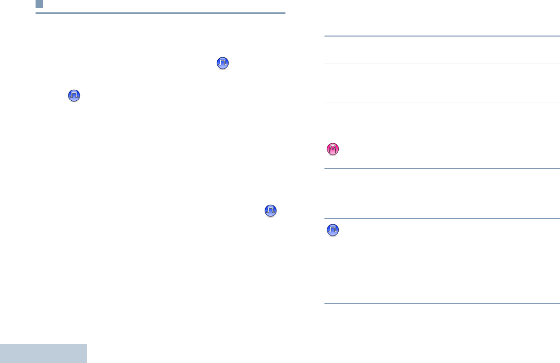
Accessing the Programmed Functions
You can access various radio functions through one of the
following ways:
•A short or long press of the
relevant programmable buttons.
OR
•Use the Menu Navigation Buttons as follows:
1To access the menu, press the c button. Press the
appropriate Menu Scroll button (<or >) to access
the menu functions.
2To select a function or enter a sub-menu, press the e
button.
3To go back one menu level, or to return to the previous
screen, press the d button. Long press the d button
to return to the Home screen.
NOTE: Your radio automatically exits the menu after a
period of inactivity and returns to your Home
screen.
<
c e
>
d
* Not applicable in Capacity Plus
LKP_NAG-LACR.book Page 9 Tuesday, September 6, 2011 5:01 PM
English
10
Push-To-Talk (PTT) Button
The PTT button on the side of the radio serves two basic
purposes:
•While a call is in progress, the PTT button allows the radio to
transmit to other radios in the call.
Press and hold down PTT button to talk. Release the PTT
button to listen.
The microphone is activated when the PTT button is pressed.
•While a call is not in progress, the PTT button is used to make
a new call (see Making a Radio Call on page 22).
If the Talk Permit Tone (see Turning the Talk Permit Tone On
or Off on page 61) or the PTT Sidetone is enabled, wait
until the short alert tone ends before talking.
During a call, if the Channel Free Indication feature is
enabled on your radio (programmed by your dealer), you
will hear a short alert tone the moment the target radio (the
radio that is receiving your call) releases the PTT button,
indicating the channel is free for you to respond.
You will also hear the Channel Free Indication tone if your
call is interrupted, for example when the radio receives an
Emergency Call.
You can turn off the Channel Free Indication tone or the
PTT Sidetone by disabling all radio tones and alerts
(see Turning the Radio Tones/Alerts On or Off on
page 60).
PTT
Button
LKP_NAG-LACR.book Page 10 Tuesday, September 6, 2011 5:01 PM

English
11
Switching Between Conventional Analog and
Digital Mode
Each channel in your radio can be configured as a conventional
analog or conventional digital channel. Use the Channel
Selector Knob to switch between an analog or a digital channel.
When switching from digital to analog mode, certain features
are unavailable. Icons for the digital features (such as
Messages) reflect this change by appearing ‘grayed out’.
Disabled features are hidden in the menu.
Your radio also has features available in both analog and digital
mode. However, the minor differences in the way each feature
works does NOT affect the performance of your radio.
NOTE: Your radio also switches between digital and
analog modes during a dual mode scan (see Scan
on page 31).
Capacity Plus
Capacity Plus is a single-site trunking configuration of the
MOTOTRBO radio system, which uses a pool of channels to
support hundreds of users and up to 254 Groups. This feature
allows your radio to efficiently utilize the available number of
programmed channels while in Repeater Mode.
You can only access channel(s) with Capacity Plus via the
Channel Selector Knob, while features supported in Capacity
Plus can be accessed via the menu and/or a programmable
button press.
Icons of features not applicable to Capacity Plus will not be
available in the menu. You will hear a negative indicator tone if
you access a feature not applicable to Capacity Plus via a
programmable button press.
Your radio also has features that are available in both
conventional digital mode and Capacity Plus. However, the
minor differences in the way each feature works does NOT
affect the performance of your radio. A Software License Key
sold separately is required for this feature.
Check with your dealer or system administrator for more
information on this system.
Channel
Selector
Knob
LKP_NAG-LACR.book Page 11 Tuesday, September 6, 2011 5:01 PM
English
12
Display Icons
The 132 x 36 pixels, monochrome display, liquid crystal display
(LCD) of your radio shows radio status, text entries, and menu
entries.
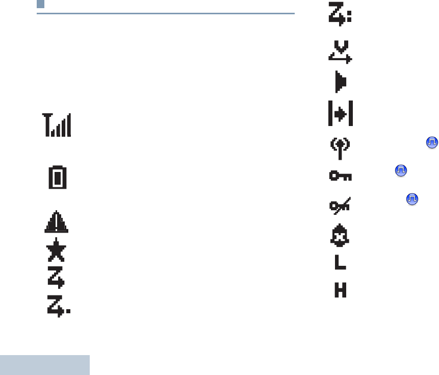
The following are icons that appear on the status bar at the top
of the radio’s display. Icons are displayed on the status bar,
arranged left-to-right, in order of appearance/usage.
Received Signal Strength Indicator (RSSI)
The number of bars displated represents the radio
signal strength. Four bars indicate the strongest
signal. The icon is only displayed while receiving.
Battery
The number of bars (0 – 4) shown indicates the
charge remaining in the battery. Blinks when the
battery is low.
Emergency
Radio is in emergency mode.
Notification
Notification list is not empty.
Scan*
Scan feature is enabled.
Scan – Priority 1*
Radio detects activity on channel/group designated as
Priority 1
Scan Priority 2*
Radio detects activity on channel/group designated as
Priority 2.
Vote Scan
Vote scan feature is enabled.
Monitor
Selected channel is being monitored.
Talkaround*
In the absence of a repeater, radio is currently
configured for direct radio to radio communication.
Site Roaming*
The site roaming feature is enabled.
Secure
The Privacy feature is enabled.
Unsecure
The Privacy feature disabled.
Tones Disabled
Tones are turned off.
Power Level
Radio is set at Low Power
Radio is set at High Power
OR
LKP_NAG-LACR.book Page 12 Tuesday, September 6, 2011 5:01 PM
English
13
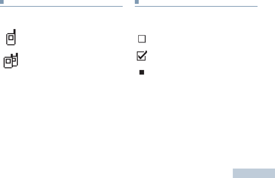
Call Icons
The following icons appear on the radio’s display during a call.
These icons also appear in the Contacts list to indicate ID type.
Advanced Menu Icons
The following icons appear beside menu items that offer a
choice between two options or as an indication that there is a
sub-menu offering two options.
Private Call
Indicates a Private Call in progress. In the Contacts
list, it indicates a subscriber alias (name) or ID
(number).
Group Call/All Call
Indicates a Group Call or All Call in progress. In the
Contacts list, it indicates a group alias (name) or ID
(number)
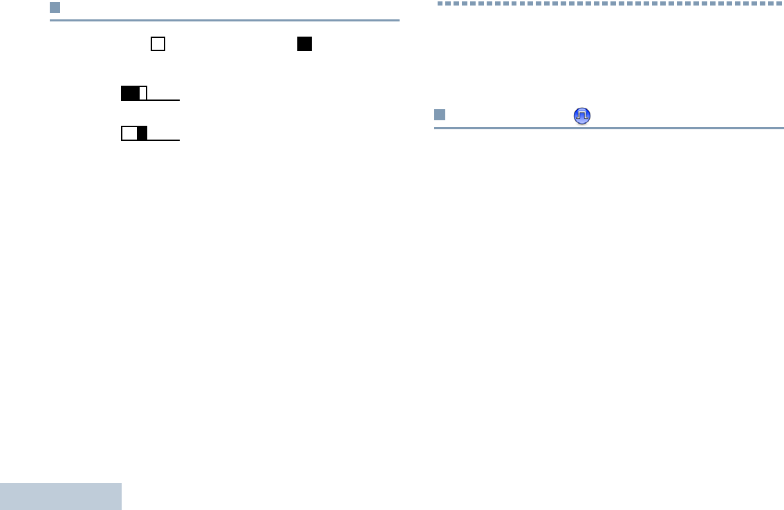
Checkbox (Empty)
Indicates the option is not selected.
Checkbox (Checked)
Indicates the option is selected.
Solid Black Box
Indicates the option selected for the menu item with a
sub-menu.
LKP_NAG-LACR.book Page 13 Tuesday, September 6, 2011 5:01 PM
English
14
Mini Notice Icons
The following icons appear momentarily on the radio’s display
after an action to perform task is take.
LED Indicator
The LED indicator shows the operational status of your radio.
Blinking red – Radio is transmitting at low battery condition,
receiving an emergency transmission or has failed the self-test
upon powering up.
Solid yellow – Radio is monitoring a conventional channel.
Blinking yellow – Radio is scanning for activity or receiving a
Call Alert.
Successful Transmission (Positive)
Successful action taken.
Failed Transmission (Negative)
Failed action taken.
Transmission in Progress (Transitional)
Transmitting. This dynamic icon is seen before
indication for Successful Transmission or Failed
Transmission.
LED Indicator
LKP_NAG-LACR.book Page 14 Tuesday, September 6, 2011 5:01 PM
English
15
Double blinking yellow – Radio is no longer connected to the
repeater while in Capacity Plus, all Capacity Plus channels are
currently busy. Auto roaming is enabled, radio is actively
searching for a new site. Also indicates radio has yet to respond
to a group call alert, or radio is locked.
Solid green – Radio is powering up, or transmitting.
Blinking green – Radio is receiving a non-privacy-enabled call
or data, or detecting activity over the air.
Double blinking green – Radio is receiving a privacy-enabled
call or data.
NOTE: While in conventional mode, when the LED blinks
green, it indicates the radio detects activity over
the air. Due to the nature of the digital protocol, this
activity may or may not affect the radio's
programmed channel.
For Capacity Plus, there is no LED indication when
the radio is detecting activity over the air.
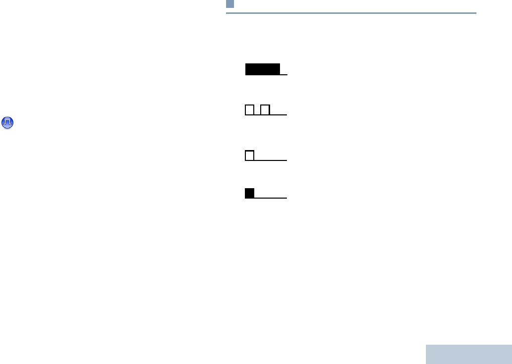
Audio Tones
Alert tones provide you with audible indications of the radio’s
status or the radio’s response to data received.
Continuous Tone A monotone sound. Sounds
continuously until termination.
Periodic Tone Sounds periodically depending on the
duration set by the radio. Tone starts,
stops, and repeats itself.
Repetitive Tone A single tone that repeats itself until it is
terminated by the user.
Momentary Tone Sounds only once for a short period of
time defined by the radio.
* Not applicable in Capacity Plus
LKP_NAG-LACR.book Page 15 Tuesday, September 6, 2011 5:01 PM
Making and Receiving Calls
English
16
Indicator Tones
High pitched tone Low pitched tone
Making and Receiving Calls
Once you understand how your MOTOTRBO Portable is
configured, you are ready to use your radio.
Selecting a Site
A site is a specific area where a base station is placed to
provide optimal coverage for the radio.
If enabled, your radio is able to connect to different available
sites via an Internet Protocol (IP) network.
See IP Site Connect on page 51 for more information.
Positive Indicator Tone
Negative Indicator Tone
OR
LKP_NAG-LACR.book Page 16 Tuesday, September 6, 2011 5:01 PM
Making and Receiving Calls
English
17
Selecting a Zone
A zone is a group of channels. Your radio supports up to 128
channels and 50 zones, with a maximum of 16 channels per
zone.
Use the following procedure to select a zone.
Procedure:
Press the programmed Zone button and proceed to Step 3.
OR
Follow the procedure below.
1c to access the menu.
2< or > to Zone and press e to select.
3The current zone is displayed and indicated by a 9.
4< or > to the required zone and press e to select.
5The display shows <Zone> Selected momentarily and
returns to the selected zone screen.
Selecting a Radio Channel, Subscriber ID,
or Group ID
Procedure:
Once the required zone is displayed (if you have multiple
zones in your radio), turn the programmed Channel Selector
Knob to select the channel.
LKP_NAG-LACR.book Page 17 Tuesday, September 6, 2011 5:01 PM
Making and Receiving Calls
English
18
Receiving and Responding to a Radio Call
Once the channel, subscriber
ID or group ID is displayed,
you can proceed to receive
and respond to calls.
The LED lights up solid green
while the radio is transmitting
and blinks green when the
radio is receiving.
NOTE: The LED lights up solid green while the radio is
transmitting and double blinks green when the
radio is receiving a privacy-enabled call.
To unscramble a privacy-enabled call, your radio
must have the same Privacy Key, OR the same Key
Value and Key ID (programmed by your dealer), as
the transmitting radio (the radio you are receiving
the call from).
See Privacy on page 50 for more information.
Receiving and Responding to a Group Call
To receive a call from a group of users, your radio must be
configured as part of that group.
Procedure:
When you receive a Group Call (while on the Home screen):
1The LED blinks green.
2The Group Call icon appears in the top right corner. The first
text line shows the caller alias. The second text line displays
the group call alias..
3Hold the radio vertically 1 to 2 inches (2.5 to 5.0 cm) from
your mouth.
4 If the Channel Free Indication feature is enabled, you
will hear a short alert tone the moment the transmitting radio
releases the PTT button, indicating the channel is free for
you to respond.
Press the PTT button to respond to the call.
OR
If the Voice Interrupt feature is enabled, press the PTT
button to stop the current call from the transmitting radio and
free the channel for you to talk/respond.
LED
Indicator
LKP_NAG-LACR.book Page 18 Tuesday, September 6, 2011 5:01 PM

Making and Receiving Calls
English
19
5The LED lights up solid green.
6Wait for the Talk Permit Tone to finish (if enabled) and
speak clearly into the microphone.
OR
Wait for the PTT Sidetone to finish (if enabled) and
speak clearly into the microphone.
7Release the PTT button to listen.
8If there is no voice activity for a predetermined period of
time, the call ends.
See Making a Group Call on page 22 for details on making a
Group Call.
NOTE: If the radio receives a Group Call while not on the
Home screen, it remains on its current screen prior
to answering the call.
Long press the d button to go to the Home
screen to view the caller alias before replying.
Receiving and Responding to a Private Call
A Private Call is a call from an individual radio to another
individual radio.
There are two types of Private Calls. The first type, where a
radio presence check is performed prior to setting up the call,
while the other sets up the call immediately.
When your radio is checked, the LED blinks green.
Only one of these call types can be programmed to your radio
by your dealer.
Procedure:
When you receive a Private Call:
1The LED blinks green.
2The first text line shows private call icon. The second text
line displays the private call alias.
3Hold the radio vertically 1 to 2 inches (2.5 to 5.0 cm) from
your mouth.
LKP_NAG-LACR.book Page 19 Tuesday, September 6, 2011 5:01 PM

Making and Receiving Calls
English
20
4If the Channel Free Indication feature is enabled, you will
hear a short alert tone the moment the transmitting radio
releases the PTT button, indicating the channel is free for
you to respond.
Press the PTT button to respond to the call.
OR
If the Voice Interrupt feature is enabled, press the PTT
button to stop the current call from the transmitting radio and
free the channel for you to talk/respond.
5The LED lights up solid green.
6Wait for the Talk Permit Tone to finish (if enabled) and
speak clearly into the microphone.
7Release the PTT button to listen.
8If there is no voice activity for a predetermined period of
time, the call ends.
9You hear a short tone. The display shows Call Ended.
See Making a Private Call on page 23 for details on making a
Private Call.
Receiving an All Call
An All Call is a call from an individual radio to every radio on the
channel. It is used to make important announcements requiring
the user’s full attention.
Procedure:
When you receive an All Call:
1A tone sounds and the LED blinks green.
2The Group Call icon appears in the top right corner. The first
text line shows the caller alias. The second text line displays
All Call.
3Once the All Call ends, the radio returns to the previous
screen before receiving the call.
If the Channel Free Indication feature is enabled, you
will hear a short alert tone the moment the transmitting radio
releases the PTT button, indicating the channel is now
available for use.
You cannot respond to an All Call.
See Making an All Call on page 23 for details on making an All
Call.
NOTE: The radio stops receiving the All Call if you switch
to a different channel while receiving the call.
During an All Call, you will not be able to use any
programmed button functions until the call ends.
LKP_NAG-LACR.book Page 20 Tuesday, September 6, 2011 5:01 PM

Making and Receiving Calls
English
21
Receiving and Responding to a Selective Call
A Selective Call is a call from an individual radio to another
individual radio. It is a Private Call on an analog system.
Procedure:
When you receive a Selective Call:
1The LED blinks green.
2The Private Call icon appears in the top right corner. The
first text line shows the caller alias or Selective Call or
Alert with Call.
3Hold the radio vertically 1 to 2 inches (2.5 to 5.0 cm) from
your mouth.
4If the Channel Free Indication feature is enabled, you will
hear a short alert tone the moment the transmitting radio
releases the PTT button, indicating the channel is free for
you to respond.
Press the PTT button to respond to the call.
5The LED lights up solid green.
6Wait for the Talk Permit Tone to finish (if enabled) and
speak clearly into the microphone.
7Release the PTT button to listen.
8If there is no voice activity for a predetermined period of
time, the call ends.
You hear a short tone. The display shows Call Ended.
NOTE: See Making a Selective Call on page 24 for details on
making a Private Call.
LKP_NAG-LACR.book Page 21 Tuesday, September 6, 2011 5:01 PM
Making and Receiving Calls
English
22
Making a Radio Call
You can select a channel, subscriber ID, or group by using:
•The Channel Selector Knob
•A programmed One Touch Access button
•A programmable button – This method is for Phone Calls
only.
•The Contacts list (see Contacts Settings on page 34)
NOTE: Your radio must have the Privacy feature enabled
on the channel to send a privacy-enabled
transmission. Only target radios with the same
Privacy Key OR the same Key Value and Key ID as
your radio will be able to unscramble the
transmission.
See Privacy on page 50 for more information.
Making a Call with the Channel Selector Knob
Making a Group Call
To make a call to a group of users, your radio must be
configured as part of that group.
Procedure:
1Turn the Channel Selector Knob to select the channel with
the active group alias or ID.
2Hold the radio vertically 1 to 2 inches (2.5 to 5.0 cm) from
your mouth.
3Press the PTT button to make the call. The LED lights up
solid green. The first text line shows the group call icon. The
second text line shows the group call alias,
4Wait for the Talk Permit Tone to finish (if enabled) and
speak clearly into the microphone.
OR
Wait for the PTT Sidetone to finish (if enabled) and
speak clearly into the microphone.
5Release the PTT button to listen.When the target radio
responds, the LED blinks green. You see the Group Call
icon, the group alias or ID, and transmitting radio alias or ID
on your display.
6 If the Channel Free Indication feature is enabled, you
will hear a short alert tone the moment the target radio
releases the PTT button, indicating the channel is free for
you to respond. Press the PTT button to respond.
OR
If there is no voice activity for a predetermined period of
time, the call ends.
LKP_NAG-LACR.book Page 22 Tuesday, September 6, 2011 5:01 PM

Making and Receiving Calls
English
23
7Radio returns to the screen you were on prior to initiating the
call.
You can also make a Group Call via Contacts (see Making a
Group Call from Contacts on page 35).
Making a Private Call
While you can receive and/or respond to a Private Call
initiated by an authorized individual radio, your radio
must be programmed for you to initiate a Private Call.
You will hear a negative indicator tone, when you make a
Private Call via the Contacts list, Call Log, One Touch Access
button, the programmed number keys, or the Channel Selector
Knob, if this feature is not enabled.
Use the Text Message or Call Alert features to contact an
individual radio. See Call Alert Operation on page 41 for more
information.
Procedure:
1Turn the Channel Selector Knob to select the channel with
the active subscriber alias or ID.
2Hold the radio vertically 1 to 2 inches (2.5 to 5.0 cm) from
your mouth.
3Press the PTT button to make the call. The LED lights up
solid green. The first text line shows the private call icon.
The second text line displays the private call alias.
4Wait for the Talk Permit Tone to finish (if enabled) and
speak clearly into the microphone.
5Release the PTT button to listen. When the target radio
responds, the LED blinks green.
6If the Channel Free Indication feature is enabled, you will
hear a short alert tone the moment the target radio releases
the PTT button, indicating the channel is free for you to
respond. Press the PTT button to respond.
OR
If there is no voice activity for a predetermined period of
time, the call ends.
7You hear a short tone. The display shows Call Ended.
You can also make a Private Call via Contacts (see Making a
Private Call from Contacts on page 36) .
Making an All Call
This feature allows you to transmit to all users on the channel.
Your radio must be programmed to allow you to use this
feature.
Procedure:
1Turn the Channel Selector Knob to select the channel with
the active All Call group alias or ID.
2Hold the radio vertically 1 to 2 inches (2.5 to 5.0 cm) from
your mouth.
LKP_NAG-LACR.book Page 23 Tuesday, September 6, 2011 5:01 PM

Making and Receiving Calls
English
24
3Press the PTT button to make the call. The LED lights up
solid green. The first text line shows the All Call icon. The
second text line displays the All Call alias.
4Wait for the Talk Permit Tone to finish (if enabled) and
speak clearly into the microphone.
OR
Wait for the PTT Sidetone to finish (if enabled) and
speak clearly into the microphone.
Users on the channel cannot respond to an All Call.
Making a Selective Call
Just like a Private Call, while you can receive and/or
respond to a Selective Call initiated by an authorized
individual radio, your radio must be programmed for you
to initiate a Selective Call.
Procedure:
1Turn the Channel Selector Knob to select the channel with
the active subscriber alias or ID.
2Hold the radio vertically 1 to 2 inches (2.5 to 5.0 cm) from
your mouth.
3Press the PTT button to make the call. The LED lights up
solid green. The Private Call icon appears in the top right
corner. The first text line shows the subscriber alias. The
second text line displays the call status. Wait for the Talk
Permit Tone to finish (if enabled) and speak clearly into the
microphone.
OR
Wait for the PTT Sidetone to finish (if enabled) and speak
clearly into the microphone.
4Release the PTT button to listen. When the target radio
responds, the LED blinks green.
5If the Channel Free Indication feature is enabled, you will
hear a short alert tone the moment the target radio releases
the PTT button, indicating the channel is free for you to
respond. Press the PTT button to respond.
OR
If there is no voice activity for a predetermined period of
time, the call ends.
6You hear a short tone. The display shows Call Ended.
LKP_NAG-LACR.book Page 24 Tuesday, September 6, 2011 5:01 PM

Making and Receiving Calls
English
25
Making a Call with the One Touch Access
Button
The One Touch Access feature allows you to make a Group,
Private or Phone Call to a predefined alias or ID easily. This
feature can be assigned to a short or long programmable button
press.
You can ONLY have one alias or ID assigned to a One Touch
Access button. Your radio can have multiple One Touch
Access buttons programmed.
Procedure:
1Press the programmed One Touch Access button to make
a Group or Private Call to the predefined alias or ID.
2Hold the radio vertically 1 to 2 inches (2.5 to 5.0 cm) from
your mouth.
3Press the PTT button to make the call. The LED lights up
solid green. The Group/Private Call icon appears in the top
right corner. The first text line shows the caller alias. The
second text line displays the call status for a Private Call.
4Wait for the Talk Permit Tone to finish (if enabled) and
speak clearly into the microphone.
5Release the PTT button to listen. When the target radio
responds, the LED blinks green.
6If the Channel Free Indication feature is enabled, you will
hear a short alert tone the moment the target radio releases
the PTT button, indicating the channel is free for you to
respond. Press the PTT button to respond.
OR
If there is no voice activity for a predetermined period of
time, the call ends.
7Radio returns to the screen you were on prior to initiating the
call.
For a Private Call, you hear a short tone when the call ends.
LKP_NAG-LACR.book Page 25 Tuesday, September 6, 2011 5:01 PM

Making and Receiving Calls
English
26
Stopping a Radio Call
This feature allows you to stop an ongoing Group or Private Call
to free the channel for transmission. For example, when a radio
experiences a “stuck microphone” condition where the PTT
button is inadvertently pressed by the user.
Your radio must be programmed to allow you to use this
feature.
Procedure:
While on the required channel:
1Press the programmed Transmit Interrupt Remote Dekey
button.
2The display shows Remote Dekey.
3Wait for acknowledgment.
4The radio sounds a positive indicator tone and the display
shows Remote Dekey Success, indicating that the channel
is now free.
OR
The radio sounds a negative indicator tone and the display
shows Remote Dekey Failed.
On the interrupted radio, the display shows
Call
Interrupted
, and the radio sounds a negative indicator tone
until you release the PTT button, if it is transmitting an
interruptible call that is stopped via this feature.
Talkaround
You can continue to communicate when your repeater is not
operating, or when your radio is out of the repeater’s range but
within talking range of other radios.
This is called “talkaround”.
NOTE: This feature is not applicable in Capacity Plus.
Procedure:
Press the programmed Repeater/Talkaround button to toggle
between talkaround and repeater modes.
OR
Follow the procedure below.
1c to access the menu.
2< or > to Utilities and press e to select.
3< or > to Radio Settings and press e to select.
4Press e to enable Talkaround. The display shows 9
beside Enabled.
OR
Press e to disable Talkaround. The 9 disappears from
beside Enabled.
5The screen automatically returns to the previous menu.
The Talkaround setting is retained even after powering down
LKP_NAG-LACR.book Page 26 Tuesday, September 6, 2011 5:01 PM

Making and Receiving Calls
English
27
NOTE: At Step 4, you can also use < or > to change
the selected option.
Monitoring Features
Monitoring a Channel
Use the Monitor feature to make sure a channel is clear before
transmitting.
NOTE: This feature is not applicable in Capacity Plus.
Procedure:
1Press and hold the programmed Monitor button and listen
for activity.
2The Monitor icon appears on the status bar and the LED
lights up solid yellow.
3You hear radio activity or total silence, depending on how
your radio is programmed.
4When you hear “white noise” (that is, the channel is free),
press the PTT button to talk and release it to listen.
Permanent Monitor
Use the Permanent Monitor feature to continuously monitor a
selected channel for activity.
NOTE: This feature is not applicable in Capacity Plus.
Procedure:
1Press the programmed Permanent Monitor button.
2Radio sounds an alert tone, the LED lights up solid yellow,
and the display shows Permanent Monitor On. The
Monitor icon appears on the status bar.
3Press the programmed Permanent Monitor button to exit
Permanent Monitor mode.
4Radio sounds an alert tone, the LED turns off, and display
shows Permanent Monitor Off.
LKP_NAG-LACR.book Page 27 Tuesday, September 6, 2011 5:01 PM

English
28
Radio Check
If enabled, this feature allows you to determine if another radio
is active in a system without disturbing the user of that radio. No
audible or visual notification is shown on the target radio.
This feature is only applicable for subscriber aliases or IDs.
Sending a Radio Check
Procedure:
Use the programmed Radio Check button.
1Press the programmed Radio Check button.
2< or > to the required subscriber alias or ID and
press e to select.
3The display shows transitional mini notice, indicating the
request is in progress. The LED lights up solid green.
4Wait for acknowledgement.
5If successful, a positive indicator tone sounds and the
display shows positive mini notice.
OR
If unsuccessful, a negative indicator tone sounds and the
display shows negative mini notice.
6Radio returns to the subscriber alias or ID screen.
OR
Procedure:
Use the menu.
1c to access the menu.
2< or > to Contacts and press e to select.
3< or > to the required subscriber alias or ID and
press e to select.
4< or > to Radio Check and press e to select.
5The display shows transitional mini notice, indicating the
request is in progress. The LED lights up solid green.
6Wait for acknowledgement.
7If successful, a positive indicator tone sounds and the
display shows positive mini notice.
OR
If unsuccessful, a negative indicator tone sounds and the
display shows negative mini notice.
LKP_NAG-LACR.book Page 28 Tuesday, September 6, 2011 5:01 PM

English
29
8Radio returns to the subscriber alias or ID screen.
If the d button is pressed when the radio is waiting for
acknowledgement, a tone sounds, and the radio terminates all
retries and exits Radio Check mode.
Scan Lists
Scan lists are created and assigned to individual channels/
groups. Your radio scans for voice activity by cycling through
the channel/group sequence specified in the scan list for the
current channel/group.
Your radio can support up to 250 scan lists, with a maximum of
16 members in a list. Each scan list supports a mixture of both
analog and digital entries.
You can add, delete, or prioritize channels by editing a scan list.
You can attach a new scan list to your radio via Front Panel
Programming.
NOTE: This feature is not applicable in Capacity Plus.
Viewing an Entry in the Scan List
Procedure:
1c to access the menu.
2< or > to Scan and press e to select.
3< or > to Scan List and press e to select.
4Use < or > to view each member on the list.
The priority icon appears left of the member’s alias, if set, to
indicate whether the member is on a Priority 1 or Priority 2
LKP_NAG-LACR.book Page 29 Tuesday, September 6, 2011 5:01 PM

English
30
channel list. You cannot have multiple Priority 1 or Priority 2
channels in a scan list.
There is no priority icon if priority is set to None.
Editing the Scan List
Adding a New Entry to the Scan List
Procedure:
1c to access the menu.
2< or > to Scan and press e to select.
3< or > to Scan List and press e to select.
4< or > to Add Member and press e to select.
5< or > to the required alias or ID.
6< or > to the required priority level and press e to
select.
7The display shows positive mini notice, followed
immediately by Add Another?.
8< or > to Yes and press e to select, to add another
entry, and repeat Steps 5 to 8.
OR
< or > to No and press e to select to save the
current list.
Deleting an Entry from the Scan List
Procedure:
1c to access the menu.
2< or > to Scan and press e to select.
3< or > to Scan List and press e to select.
4< or > to the required alias or ID.
5Press e to select.
6< or > to Delete and press e to select.
7At Delete Entry?, < or > to Yes and press e to
select, to delete the entry. The display shows positive mini
notice.
OR
< or > to No and press e to select to return to the
previous screen.
8Repeat Steps 4 to 9 to delete other entries.
After deleting all required aliases or IDs, long press d to
return to the Home screen.
LKP_NAG-LACR.book Page 30 Tuesday, September 6, 2011 5:01 PM

English
31
Setting and Editing Priority for an Entry in the Scan
List
Procedure:
1c to access the menu.
2< or > to Scan and press e to select.
3< or > to Scan List and press e to select.
4< or > to the required alias or ID.
5Press c to select.
6< or > to Edit Priority and press e to select.
7< or > to the required priority level and press e to
select.
8The display shows positive mini notice before returning to
the previous screen.
9The priority icon appears left of the member’s name.
There is no priority icon if priority is set to None.
Scan
When you start a scan, your radio cycles through the
programmed scan list for the current channel looking for voice
activity.
The LED blinks yellow and the scan icon appears on the status
bar.
During a dual mode scan, if you are on a digital channel, and
your radio locks onto an analog channel, it automatically
switches from digital mode to analog mode for the duration of
the call. This is also true for the reverse.
There are two ways of initiating scan:
•Main Channel Scan (Manual): Your radio scans all the
channels/groups in your scan list. On entering scan, your
radio may – depending on the settings – automatically start
on the last scanned “active” channel/group or on the channel
where scan was initiated.
•Auto Scan (Automatic): Your radio automatically starts
scanning when you select a channel/group that has Auto
Scan enabled.
NOTE: This feature is not applicable in Capacity Plus.
LKP_NAG-LACR.book Page 31 Tuesday, September 6, 2011 5:01 PM

English
32
Starting and Stopping Scan
Procedure:
Press the programmed Scan button to start or stop Scan.
OR
Follow the procedure below.
1Use the Channel Selector Knob to select a channel
programmed with a scan list.
2c to access the menu.
3< or > to Scan and press e to select.
4< or > to Scan State and press e to select.
5< or > to required scan state and press e to select.
6The display shows Scan On when scan is enabled. The LED
blinks yellow and the scan icon appears.
OR
The display shows Scan Off if scan is disabled. The LED
turns off and the scan icon disappears.
While scanning, the radio will only accept data (e.g. text
message, location, or PC data) if received on its Selected
Channel.
Responding to a Transmission During a Scan
During scanning, your radio stops on a channel/group where
activity is detected. The radio stays on that channel for a
programmed time period known as “hang time”.
Procedure:
1Hold the radio vertically 1 to 2 inches (2.5 to 5.0 cm) from
your mouth.
If the Channel Free Indication feature is enabled, you
will hear a short alert tone the moment the transmitting radio
releases the PTT button, indicating the channel is free for
you to respond.
2Press the PTT button during hang time. The LED lights up
solid green.
3Wait for the Talk Permit Tone to finish (if enabled) and
speak clearly into the microphone.
OR
Wait for the PTT Sidetone to finish (if enabled) and
speak clearly into the microphone.
4Release the PTT button to listen.
5If you do not respond within the hang time, the radio returns
to scanning other channels/groups.
LKP_NAG-LACR.book Page 32 Tuesday, September 6, 2011 5:01 PM

English
33
Deleting a Nuisance Channel
If a channel continually generates unwanted calls or noise
(termed a “nuisance” channel), you can temporarily remove the
unwanted channel from the scan list.
This capability does not apply to the channel designated as the
Selected Channel.
Procedure:
1When your radio “locks on to” an unwanted or nuisance
channel, press the programmed Nuisance Channel Delete
button until you hear a tone.
2Release the Nuisance Channel Delete button. The
nuisance channel is deleted.
Deleting a “nuisance” channel is only possible through the
programmed Nuisance Channel Delete button. This feature is
not accessible through the menu.
Restoring a Nuisance Channel
Procedure:
To restore the deleted nuisance channel, do one of the
following:
•Turn the radio off and then power it on again, OR
•Stop and restart a scan via the programmed Scan button or
menu, OR
•Change the channel via the Channel Selector Knob.
LKP_NAG-LACR.book Page 33 Tuesday, September 6, 2011 5:01 PM

English
34
Vote Scan
Vote Scan provides you with wide area coverage in areas
where there are multiple base stations transmitting identical
information on different analog channels.
Your radio scans analog channels of multiple base stations and
performs a voting process to select the strongest received
signal. Once that is established, your radio unmutes to
transmissions from that base station.
The LED blinks yellow and the vote scan icon appears on the
status bar.
To respond to a transmission during a Vote Scan, follow the
same procedures as Responding to a Transmission During a
Scan on page 32.
Contacts Settings
Contacts provides “address-book” capabilities on your radio.
Each entry corresponds to an alias or ID that you use to initiate
a call.
Each entry, depending on context, associates with one of five
types of calls: Group Call, Private Call, All Call, PC Call or
Dispatch Call.
PC Call and Dispatch Call are data-related. They are only
available with the applications. Refer to the data applications
documentation for more information.
NOTE: If the Privacy feature is enabled on a channel, you
can make privacy-enabled Group Call, Private Call,
and All Call on that channel. Only target radios with
the same Privacy Key OR the same Key Value and
Key ID as your radio will be able to unscramble the
transmission.
See Privacy on page 50 for more information.
Your radio supports two Contacts lists, one for Analog contacts
and one for Digital contacts, with a maximum of 500 members
for each Contacts list.
Each entry within Contacts displays the following information:
•Call Type
•Call Alias
•Call ID
LKP_NAG-LACR.book Page 34 Tuesday, September 6, 2011 5:01 PM

English
35
NOTE: You can add, or edit subscriber IDs for the Digital
Contacts list. Deleting subscriber IDs can only be
performed by your dealer.
For the Analog Contacts list, you can only view the
subcriber IDs, edit the subscriber IDs, and initiate a
Call Alert. Adding and deleting capabilities can only be
performed by your dealer.
Making a Group Call from Contacts
Procedure:
1c to access the menu.
2< or > to Contacts and press e to select.The
entries are alphabetically sorted.
3< or > to the required group alias or ID.
4Hold the radio vertically 1 to 2 inches (2.5 to 5.0 cm) from
your mouth.
5Press the PTT button to make the call. The LED lights up
solid green.
6Wait for the Talk Permit Tone to finish (if enabled) and
speak clearly into the microphone.
OR
Wait for the PTT Sidetone to finish (if enabled) and
speak clearly into the microphone.
7Release the PTT button to listen. When any user in the
group responds, the LED blinks green. You see the Group
Call icon, the group ID, and that user’s ID on your display.
8 If the Channel Free Indication feature is enabled, you
will hear a short alert tone the moment the target radio
releases the PTT button, indicating the channel is free for
you to respond. Press the PTT button to respond.
OR
If there is no voice activity for a programmed period of time,
the call ends.
LKP_NAG-LACR.book Page 35 Tuesday, September 6, 2011 5:01 PM
English
36
Making a Private Call from Contacts
Procedure:
1c to access the menu.
2< or > to Contacts and press e to select.The
entries are alphabetically sorted.
3< or > to the required subscriber alias or ID.
4Press e to select.
5Hold the radio vertically 1 to 2 inches (2.5 to 5.0 cm) from
your mouth.
6Press the PTT button to make the call. The LED lights up
solid green. The display shows the destination alias.
7Wait for the Talk Permit Tone to finish (if enabled) and
speak clearly into the microphone.
8Release the PTT button to listen. When the target radio
responds, the LED blinks green and the display shows the
transmitting user's ID.
9If the Channel Free Indication feature is enabled, you will
hear a short alert tone the moment the target radio releases
the PTT button, indicating the channel is free for you to
respond. Press the PTT button to respond.
OR
If there is no voice activity for a programmed period of time,
the call ends.
10 You hear a short tone. The display shows Call Ended.
Setting Default Contact
Procedure:
Follow the procedure below.
1c to access the menu.
2< or > to Contacts and press e to select.
3< or > to the required alias or ID and press e to
select.
4< or > to Set as Default and press e to select.
5The radio sounds a positive indicator tone and the display
shows positive mini notice.
6A 9 appears beside the selected default alias or ID.
LKP_NAG-LACR.book Page 36 Tuesday, September 6, 2011 5:01 PM

English
37
Call Indicator Settings
Activating and Deactivating Call Ringers for Call
Alert
You can select, or turn on or off ringing tones for a received Call
Alert.
Procedure:
1c to access the menu.
2< or > to Utilities and press e to select.
3< or > to Radio Settings and press e to select.
4< or > to Tones/Alerts and press e to select.
5< or > to Call Ringers and press e to select.
6< or > to Call Alert and press e to select. The
current tone is indicated by a 9.
7< or > to the required tone and press e to select. 9
appears beside selected tone.
NOTE: At Step 6, you can also use < or > to change the
selected option.
Activating and Deactivating Call Ringers for
Private Calls
You can turn on or off the ringing tones for a received Private
Call.
Procedure:
1c to access the menu.
2< or > to Utilities and press e to select.
3< or > to Radio Settings and press e to select.
4< or > to Tones/Alerts and press e to select.
5< or > to Call Ringers and press e to select.
6< or > to Private Call.
7Press e to enable Private Call ringing tones. The display
shows 9 beside Enabled.
OR
Press e to disable Private Call ringing tones. The 9
disappears from beside Enabled.
NOTE: At Step 6, you can also use < or > to change the
selected option.
LKP_NAG-LACR.book Page 37 Tuesday, September 6, 2011 5:01 PM

English
38
Activating and Deactivating Call Ringers for
Selective Call
You can select, or turn on or off ringing tones for a received
Selective Call.
Procedure:
1c to access the menu.
2< or > to Utilities and press e to select.
3< or > to Radio Settings and press e to select.
4< or > to Tones/Alerts and press e to select.
5< or > to Call Ringers and press e to select.
6< or > to Selective Call and press e to select.
The current tone is indicated by a 9.
7< or > to the required tone and press e to select. 9
appears beside selected tone.
NOTE: At Step 6, you can also use < or > to change the
selected option.
Activating and Deactivating Call Ringers for Text
Message
You can select, or turn on or off the ringing tones for a received
Text Message.
Procedure:
1c to access the menu.
2< or > to Utilities and press e to select.
3< or > to Radio Settings and press e to select.
4< or > to Tones/Alerts and press e to select.
5< or > to Call Ringers and press e to select.
6< or > to Messages and press e to select. The
current tone is indicated by a 9.
7 < or > to the required tone and press e to select. 9
appears beside selected tone.
NOTE: At Step 6, you can also use < or > to change the
selected option.
LKP_NAG-LACR.book Page 38 Tuesday, September 6, 2011 5:01 PM

English
39
Assigning Ring Styles
You can program your radio to sound one of ten predefined
ringing tones when receiving a Call Alert or a Text Message
from a particular contact.
Procedure:
1c to access the menu.
2< or > to Contacts and press e to select.The
entries are alphabetically sorted.
3< or > to the required alias or ID and press e to
select.
4< or > to Edit and press e to select.
5Press c until display shows Edit Ringtone menu.
6A 9 indicates the current selected tone.
7< or > to the required tone and press e to select. 9
appears beside selected tone.
8The display shows a positive mini notice.
The radio sounds out each ring style as you navigate through
the list.
Escalating Alarm Tone Volume
You can program your radio to continually alert you when a
radio call remains unanswered. This is done by automatically
increasing the alarm tone volume over time. This feature is
known as Escalert.
Procedure:
1c to access the menu.
2< or > to Utilities and press e to select.
3< or > to Radio Settings and press e to select.
4< or > to Tones/Alerts and press e to select.
5< or > to Escalert.
6Press e to enable Escalert. The display shows 9 beside
Enabled.
OR
Press e to disable Escalert. The 9 disappears from beside
Enabled.
NOTE: At Step 5, you can also use < or > to change the
selected option.
LKP_NAG-LACR.book Page 39 Tuesday, September 6, 2011 5:01 PM

English
40
Call Log Features
Your radio keeps track of all recent outgoing, answered, and
missed Private Calls. Use the call log feature to view and
manage recent calls.
You can perform the following tasks in each of your call lists:
•Delete
•View Details
Viewing Recent Calls
The lists are Missed, Answered, and Outgoing.
Procedure:
1c to access the menu.
2< or > to Call Log and press e to select.
3< or > to required list and press e to select.
4The display shows the most recent entry at the top of the
list.
5< or > to view the list.
Press the PTT button to start a Private Call with the current
selected alias or ID.
Deleting a Call from a Call List
Procedure:
1c to access the menu.
2< or > to Call Log and press e to select.
3< or > to the required list and press e to select.
4< or > to the required alias or ID and press e to
select.
5< or > to Delete and press e to select.
6Press e to select Yes to delete the entry. The display
shows positive mini notice.
OR
< or > to No to return to the previous screen.
When you select a call list and it contains no entries, the display
shows
List Empty
,.
Viewing Details from a Call List
Procedure:
1c to access the menu.
2< or > to Call Log and press e to select.
3< or > to the required list and press e to select.
LKP_NAG-LACR.book Page 40 Tuesday, September 6, 2011 5:01 PM

English
41
4< or > to the required alias or ID and press e to
select.
5< or > to View Details and press e to select.
Display shows details.
Call Alert Operation
Call Alert paging enables you to alert a specific radio user to call
you back when they are able to do so.
This feature is applicable for subscriber aliases or IDs only and
is accessible through the menu via Contacts.
Receiving and Responding to a Call Alert
When you receive a Call Alert page, you see the notification list
listing a Call Alert with the alias or ID of the calling radio on the
display.
Procedure:
1You hear a repetitive tone. The LED blinks yellow.
2Press the PTT button while the display still shows the Call
Alert in the Notification List to respond with a Private Call.
OR
Press d to exit the Notification List. The alert is moved to
the Missed Call Log.
See Notification List on page 59 for details about the
Notification List.
See Call Log Features on page 40 for details about the Missed
Call List.
LKP_NAG-LACR.book Page 41 Tuesday, September 6, 2011 5:01 PM

English
42
Making a Call Alert from the Contacts List
Procedure:
1c to access the menu.
2< or > to Contacts and press e to select.
3< or > to the required subscriber alias or ID and
press e to select.
4< or > to Call Alert and press e to select.
5The display shows Call Alert and the subscriber alias or
ID, indicating that the Call Alert has been sent.
6The LED lights up solid green when your radio is sending
the Call Alert.
7If the Call Alert acknowledgement is received, the display
shows positive mini notice.
OR
If the Call Alert acknowledgement is not received, the
display shows negative mini notice.
Making a Call Alert with the One Touch Access
Button
Procedure:
1Press the programmed One Touch Access button to make
a Call Alert to the predefined alias or ID.
2The display shows Call Alert and the subscriber alias or
ID, indicating that the Call Alert has been sent.
3The LED lights up solid green when your radio is sending
the Call Alert.
4If the Call Alert acknowledgement is received, the display
shows positive mini notice.
OR
If the Call Alert acknowledgement is not received, the
display shows negative mini notice.
LKP_NAG-LACR.book Page 42 Tuesday, September 6, 2011 5:01 PM

English
43
Emergency Operation
An Emergency Alarm is used to indicate a critical situation. You
are able to initiate an Emergency at any time on any screen
display even when there is activity on the current channel.
Your dealer can set the duration of a button press for the
programmed Emergency button, except for long press, which is
similar with all other buttons:
•Short press – Between 0.05 seconds and 0.75 seconds
•Long press – Between 1.00 second and 3.75 seconds
The programmed Emergency button is assigned with the
Emergency On/Off feature. Check with your dealer for the
assigned operation of the Emergency button.
If short press the programmed Emergency button is assigned
to turn on the Emergency mode, then long press the
programmed Emergency button is assigned to exit the
Emergency mode.
If long press the programmed Emergency button is assigned to
turn on the Emergency mode, then short press the programmed
Emergency button is assigned to exit the Emergency mode.
NOTE: Side Button 1 or Side Button 2 can be programmed as
the Emergency Button.
Your radio supports three Emergency Alarms:
•Emergency Alarm
•Emergency Alarm with Call
•Emergency Alarm with Voice to Follow
In addition, each alarm has the following types:
•Regular – Radio transmits an alarm signal and shows audio
and/or visual indicators.
•Silent – Radio transmits an alarm signal without any audio or
visual indicators. Radio receives calls without any sound
through the radio’s speaker, until you press the PTT button to
initiate the call.
•Silent with Voice – Radio transmits an alarm signal without
any audio or visual indicators, but allow incoming calls to
sound through the radio’s speaker.
Only ONE of the Emergency Alarms above can be assigned to
the programmed Emergency button.
LKP_NAG-LACR.book Page 43 Tuesday, September 6, 2011 5:01 PM

English
44
Sending an Emergency Alarm
This feature allows you to send an Emergency Alarm, a
non-voice signal, which triggers an alert indication on a group of
radios.
Procedure:
1Press the programmed Emergency On button.
2The display shows Tx Alarm and the destination alias. The
LED lights up solid green and the Emergency icon appears.
OR
The display shows Tx Telegram and the destination
alias. The LED lights up solid green and the Emergency icon
appears.
3When an Emergency Alarm acknowledgment is received,
the Emergency tone sounds and the LED blinks green. The
display shows Alarm Sent.
OR
If your radio does not receive an Emergency Alarm
acknowledgement, and after all retries have been
exhausted, a tone sounds and the display shows Alarm
Failed.
4Radio exits the Emergency Alarm mode and returns to the
Home screen.
If your radio is set to Silent, it will not display any audio or visual
indicators during Emergency mode.
Sending an Emergency Alarm with Call
This feature allows you to send an Emergency Alarm to a group
of radios. Upon acknowledgement by a radio within the group,
the group of radios can communicate over a programmed
Emergency channel.
Procedure:
1Press the programmed Emergency On button.
2The display shows Tx Alarm and the destination alias. The
LED lights up solid green and the Emergency icon appears.
OR
The display shows Tx Telegram and the destination
alias. The LED lights up solid green and the Emergency icon
appears.
3When an Emergency Alarm acknowledgment is received,
the Emergency tone sounds and the LED blinks green. The
display shows Alarm Sent.
4Your radio enters the emergency call mode when the
display shows Emergency and the destination group alias.
5Hold the radio vertically 1 to 2 inches (2.5 to 5.0 cm) from
your mouth.
6Press PTT button to make the call. The LED lights up solid
green and the group icon appears on the display.
LKP_NAG-LACR.book Page 44 Tuesday, September 6, 2011 5:01 PM

English
45
7Wait for the Talk Permit Tone to finish (if enabled) and
speak clearly into the microphone.
OR
Wait for the PTT Sidetone to finish (if enabled) and
speak clearly into the microphone.
8Release the PTT button to listen.
When you receive a group call, the display shows the caller
alias and group alias.
9When the channel is free for you to respond, a short alert
tone sounds ( if the Channel Free Indication feature is
enabled). Press the PTT button to respond.
OR
Once your call ends, press the programmed Emergency
Off button to exit the Emergency mode.
10 The radio returns to the Home screen.
If your radio is set to Silent, it will not display any audio or visual
indicators during Emergency mode, or allow any received calls
to sound through the radio’s speaker, until you press the PTT
button to initiate the call.
If your radio is set to Silent with Voice, it will not display any
audio or visual indicators during Emergency mode, but allow
incoming calls to sound through the radio’s speaker. The
indicators will only appear once you press the PTT button to
initiate, or respond to, the call.
Sending an Emergency Alarm with Voice to
Follow
This feature allows you to send an Emergency Alarm to a group
of radios. Your radio’s microphone is automatically activated,
allowing you to communicate with the group of radios without
pressing the PTT button.
This activated microphone state is also known as “hot mic”.
If you press the PTT button during the programmed hot mic
transmission period, the radio ignores the PTT press and
remains in Emergency mode.
NOTE: If you press the PTT button during hot mic, and
continue to press it after the hot mic duration expires,
the radio continues to transmit until you release the
PTT button.
Procedure:
1Press the programmed Emergency On button.
2The display shows Tx Alarm and the destination alias. The
LED lights up solid green and the Emergency icon appears.
OR
The display shows Tx Telegram and the destination
alias. The LED lights up solid green and the Emergency icon
appears.
3Once the display shows Alarm Sent, speak clearly into the
microphone. When hot mic has been enabled, the radio
LKP_NAG-LACR.book Page 45 Tuesday, September 6, 2011 5:01 PM

English
46
automatically transmits without a PTT press until the hot mic
duration expires.
4While transmitting, the LED lights up solid green and the
Emergency icon appears.
5Once the hot mic duration expires, the radio automatically
stops transmitting. To transmit again, press the PTT button.
6Press the programmed Emergency Off button to exit the
Emergency mode.
7The radio returns to the Home screen.
If your radio is set to Silent, it will not display any audio or
visual indicators during Emergency mode, or allow any
received calls to sound through the radio’s speaker, until the
programmed hot mic transmission period is over, and you
press the PTT button.
If your radio is set to Silent with Voice, it will not display any
audio or visual indicators during Emergency mode when you
are making the call with hot mic, but allow sound through the
radio’s speaker when the target radio responds after the
programmed hot mic transmission period is over. The
indicators will only appear when you press the PTT button.
NOTE: If the Emergency Alarm request fails, the radio does
not retry to send the request, and enters the hot mic
state directly.
Reinitiating an Emergency Mode
NOTE: This feature is only applicable to the radio sending the
Emergency Alarm.
There are two instances where this can happen:
•You change the channel while the radio is in Emergency
mode. This exits the Emergency mode. If Emergency Alarm
is enabled on this new channel, the radio reinitiates
Emergency.
•You press the programmed Emergency On button during an
Emergency initiation/transmission state. This causes the
radio to exit this state, and to reinitiate Emergency.
Exiting Emergency Mode
NOTE: This feature is only applicable to the radio sending the
Emergency Alarm.
Your radio exits Emergency mode when one of the following
occurs:
•Emergency Alarm acknowledgement is received (for
Emergency Alarm only), OR
•An Emergency Exit Telegram is received, OR
•All retries to send the alarm have been exhausted, OR
•The Emergency Off button is pressed.
LKP_NAG-LACR.book Page 46 Tuesday, September 6, 2011 5:01 PM

English
47
NOTE: If your radio is powered off, it exits the Emergency
mode. The radio will not reinitiate the Emergency mode
automatically when it is turned on again.
If you change channels when your radio is in
Emergency mode to a channel that has no emergency
system configured, No Emergency is shown on your
display.
LKP_NAG-LACR.book Page 47 Tuesday, September 6, 2011 5:01 PM

English
48
LKP_NAG-LACR.book Page 48 Tuesday, September 6, 2011 5:01 PM
English
49
Analog Message Encode
Your radio is able to send preprogrammed messages from the
Message list to a radio alias or to the dispatcher.
Sending MDC Message Encode to Dispatcher
Procedure:
1< or > to Message and press to select.
2< or > to Quick Text and press to select.
3< or > to the required message. Press to send.
4 The display shows transitional mini notice, confirming your
message is being sent.
5If the message is sent, a tone sounds and the display shows
positive mini notice.
OR
If the message is not sent, a low tone sounds and the
display shows negative mini notice.
Analog Status Update
Your radio is able to send preprogrammed messages from the
Status List indicating your current activity to a radio contact (for
5-Tone systems) or to the dispatcher (for MDC systems).
The last acknowledged message is kept at the top of the Status
List. The other messages are arranged in alphanumeric order.
Sending Status Update to Predefined Contact
Procedure:
1< or > to Status and press e to select.
2< or > to the required status. Press e to select.
3< or > to Set as Default. Press e to send the
status update.
4The display shows transitional mini notice, confirming your
status update is being sent.
5If the status update is acknowledged, a tone sounds and the
display shows positive mini notice. A 9 appears beside the
acknowledged status.
OR
If the status update is not acknowledged, a low tone sounds
and the display shows negative mini notice. A 9 remains
beside the previous status.
LKP_NAG-LACR.book Page 49 Tuesday, September 6, 2011 5:01 PM

English
50
Privacy
If enabled, this feature helps to prevent eavesdropping by
unauthorized users on a channel by the use of a software-
based scrambling solution. The signaling and user identification
portions of a transmission are not scrambled.
Your radio must have privacy enabled on the channel to send a
privacy-enabled transmission, although this is not a necessary
requirement for receiving a transmission. While on a privacy-
enabled channel, the radio is still able to receive clear
(unscrambled) transmissions.
Your radio supports two types of privacy:
•Basic Privacy
•Enhanced Privacy. (A Software License Key sold separately
is required for this feature.)
Only ONE of the privacy types above can be assigned to the
radio.
To unscramble a privacy-enabled call or data transmission, your
radio must be programmed to have the same Privacy Key (for
Basic Privacy), OR the same Key Value and Key ID (for
Enhanced Privacy) as the transmitting radio.
If your radio receives a scrambled call that is of a different
Privacy Key, OR a different Key Value and Key ID, you will
either hear a garbled transmission (Basic Privacy) or nothing at
all (Enhanced Privacy).
The LED lights up solid green while the radio is transmitting and
double blinks green when the radio is receiving an ongoing
privacy-enabled transmission.
Some radio models may not offer this Privacy feature. Check
with your dealer or system administrator for more
information.Procedure:
Press the programmed Privacy button to toggle privacy on or
off.
OR
Follow the procedure below.
1c to access the menu.
2< or > to Utilities and press e to select.
3< or > to Radio Settings and press e to select.
4< or > to Privacy
5Press e to enable Privacy. The display shows 9 beside
Enabled.
OR
Press e to disable Privacy. The 9 disappears from beside
Enabled.
If the radio has a privacy type assigned, secure or unsecure
icon appears on the status bar, except when the radio is
sending or receiving an Emergency call or alarm.
LKP_NAG-LACR.book Page 50 Tuesday, September 6, 2011 5:01 PM

English
51
NOTE: At Step 4, you can also use < or > to change the
selected option.
Dual Tone Multi Frequency (DTMF)
The Dual Tone Multi Frequency (DTMF) feature allows the radio
to operate in a radio system with an interface to telephone
systems.
Procedure:
To initiate a DTMF call.
1Press and hold the PTT button.
2Enter the desired number, * or #.
You can turn off the DTMF tone by disabling all radio tones and
alerts (see Turning the Radio Tones/Alerts On or Off on
page 60).
IP Site Connect
This feature allows your radio to extend communication beyond
the reach of a single site, by connecting to different available
sites via an Internet Protocol (IP) network. A Software License
Key sold separately is required for this feature.
NOTE: This feature is not applicable in Capacity Plus.
When the radio moves out of range from one site and into the
range of another, it connects to the new site's base station to
send or receive calls/data transmissions. Depending on your
settings, this is done automatically or manually.
If the radio is set to do this automatically, it scans through all
available sites when the signal from the current site is weak or
when the radio is unable to detect any signal from the current
site. It then locks on to the base station with the strongest
Received Signal Strength Indicator (RSSI) value.
In a manual site search, the radio searches for the next site in
the roam list that is currently in range (but which may not have
the strongest signal) and locks on to it.
NOTE: Each channel can only have either Scan or Roam
enabled, not both at the same time.
Channels with this feature enabled can be added to a particular
roam list. The radio searches the channel(s) in the Members list
during the automatic roam operation to locate the best site.
LKP_NAG-LACR.book Page 51 Tuesday, September 6, 2011 5:01 PM

English
52
A Members list supports a maximum of 16 channels (including
the Selected Channel).
NOTE: You cannot manually add or delete an entry to the
Members list. Check with your dealer or system
administrator for more information.
Starting an Automatic Site Search
NOTE: The radio only scans for a new site if the current signal
is weak or when the radio is unable to detect any signal
from the current site. If the RSSI value is strong, the
radio remains on the current site.
Procedure:
Press the programmed Site Lock On/Off button.
1A tone sounds and the display shows Site Unlocked.
2The LED blinks yellow rapidly when the radio is actively
searching for a new site, and turns off once the radio locks
on to a site.
3The display shows the channel alias and the site roaming
icon appears.
OR
Procedure:
Use the menu.
1c to access the menu.
2< or > to Utilities and press e to select.
3< or > to Radio Settings and press e to select.
4< or > to Site Roaming and press e to select.
5< or > to Unlock Site and press e to select. A
tone sounds and the display shows Site Unlocked.
6The radio returns to the Home screen.
7The LED blinks yellow rapidly when the radio is actively
searching for a new site, and turns off once the radio locks
on to a site.
The radio also performs an automatic site search (site is
unlocked) during a PTT button press or data transmission if
the current channel, an IP Site Select channel with an
attached roam list, is out of range.
LKP_NAG-LACR.book Page 52 Tuesday, September 6, 2011 5:01 PM

English
53
Stopping an Automatic Site Search
When the radio is actively searching for a new site:
Procedure:
Press the programmed Site Lock On/Off button.
1A tone sounds and the display shows Site Locked.
2The LED turns off and the display shows the channel alias.
OR
Procedure:
Use the menu.
1c to access the menu.
2< or > to Utilities and press e to select.
3< or > to Radio Settings and press e to select.
4< or > to Site Roaming and press e to select.
5< or > to Lock Site State.
6Press e to lock site. The display shows 9 beside Enabled.
OR
Press e to unlock site. The 9 disappears from beside
Enabled.
7The LED turns off and the radio returns to the Home screen.
The display shows the channel alias.
NOTE: At Step 5, you can also use < or > to change
the selected option.
Starting a Manual Site Search
Procedure:
Press the programmed Manual Site Roam button and proceed
to Step 6.
OR
Follow the procedure below.
1c to access the menu.
2< or > to Utilities and press c to select.
3< or > to Radio Settings and press c to select.
4< or > to Site Roaming and press c to select.
5< or > to Active Search and press c to select.
6A tone sounds and the display shows Finding Site.
The LED blinks green.
7If a new site is found, a tone sounds and the LED turns off.
The display shows Site <Alias> Found.
OR
If there is no available site within range, a tone sounds and
the LED turns off. The display shows Out of Range.
OR
If a new site is within range, but the radio is unable to
LKP_NAG-LACR.book Page 53 Tuesday, September 6, 2011 5:01 PM

English
54
connect to it, a tone sounds and the LED turns off. The
display shows Channel Busy.
8The radio returns to the Home screen.
Security
You can enable or disable any radio in the system. For
example, you might want to disable a stolen radio, to prevent
the thief from using it, and enable that radio, when it is
recovered.
NOTE: Performing Radio Disable and Enable is limited to
radios with these functions enabled. Check with your
dealer or system administrator for more information.
Radio Disable
Procedure:
Use the programmed Radio Disable button.
1Press the programmed Radio Disable button.
2< or >to the required alias or ID and press e to
select.
3The display shows transitional mini notice, indicating the
request is in progress. The LED blinks green.
4Wait for acknowledgment.
5If successful, a positive indicator tone sounds and the
display shows positive mini notice.
OR
If unsuccessful, a negative indicator tone sounds and the
display shows negative mini notice.
LKP_NAG-LACR.book Page 54 Tuesday, September 6, 2011 5:01 PM

English
55
OR
Procedure:
Use the menu.
1c to access the menu.
2< or > to Contacts and press e to select. The
entries are alphabetically sorted.
3< or > to the required alias or ID and press e to
select.
< or > to Radio Disable and press e to select.
4 The display shows transitional mini notice, indicating the
request is in progress. The LED blinks green.
5Wait for acknowledgment.
6If successful, a positive indicator tone sounds and the
display shows positive mini notice.
OR
If unsuccessful, a negative indicator tone sounds and the
display shows negative mini notice.
Do not press d during the Radio Disable operation as you
will not get an acknowledgement message.
Radio Enable
Procedure:
Use the programmed Radio Enable button.
1Press the programmed Radio Enable button.
2< or > to the required alias or ID and press e to
select.
3 The display shows Radio Enable and the subscriber alias
or ID. The LED lights up solid green.
4Wait for acknowledgment.
5If successful, the radio sounds a positive indicator tone and
the display shows positive mini notice.
OR
If unsuccessful, the radio sounds a negative indicator tone
and the display shows negative mini notice.
OR
Procedure:
Use the menu.
1c to access the menu.
2< or > to Contacts and press e to select. The
entries are alphabetically sorted.
3< or > to the required alias or ID and press e to
select.
LKP_NAG-LACR.book Page 55 Tuesday, September 6, 2011 5:01 PM

English
56
4< or > to Radio Enable and press e to select. The
LED blinks green.
5The display shows Radio Enable and the subscriber alias
or ID. The LED lights up solid green.
6Wait for acknowledgment.
7If successful, the radio sounds a positive indicator tone and
the display shows positive mini notice.
OR
If unsuccessful, the radio sounds a negative indicator tone
and the display shows negative mini notice.
Do not press d during the Radio Enable operation as you
will not get an acknowledgement message.
Lone Worker
This feature prompts an emergency to be raised if there is no
user activity, such as any radio button press or activation of the
channel selector, for a predefined time.
Following no user activity for a programmed duration, the radio
pre-warns the user via an audio indicator once the inactivity
timer expires.
If there is still no acknowledgment by the user before the
predefined reminder timer expires, the radio initiates an
Emergency Alarm.
Only one of the following Emergency Alarms is assigned to this
feature:
•Emergency Alarm
•Emergency Alarm with Call
•Emergency Alarm with Voice to Follow
The radio remains in the emergency state allowing voice
messages to proceed until action is taken. See Emergency
Operation on page 43 on ways to exit Emergency.
NOTE: This feature is limited to radios with this function
enabled. Check with your dealer or system
administrator for more information.
LKP_NAG-LACR.book Page 56 Tuesday, September 6, 2011 5:01 PM

English
57
Password Lock Features
If enabled, this feature allows you to access your radio via
password upon powering up.
Accessing the Radio from Password
Procedure:
Power up the radio.
1You will be prompt to enter a four-digit password.
2Enter your current four-digit password. Press < or >
to choose each digit’s numeric value (0-9). Press >or
c to move to next digit. Each digit changes to ●. Press
e to confirm your selection.
You hear a positive indicator tone for every digit pressed.
Press < to remove the each ● on the display.
3If the password is correct:
Your radio proceeds to power up. See Powering Up the
Radio on page 5.
OR
If the password is incorrect:
The display shows Wrong Password. Repeat Step 2.
OR
After the third incorrect password, the display shows Wrong
Password and then, shows Radio Locked. A tone sounds
and the LED double blinks yellow.
Your radio enters into locked state for 15 minutes, and responds
to inputs from On/Off/Volume Control Knob and programmed
Backlight Auto button only.
NOTE: The radio is unable to receive any call, including
emergency calls, in locked state.
Unlocking the Radio from Locked State
Procedure:
Wait for 15 minutes. Repeat Steps 1 to 3 in Accessing the
Radio from Password on page 57.
OR
Power up the radio, if you have powered down the radio during
locked state:
1A tone sounds and the LED double blinks yellow. The
display shows Radio Locked.
2Wait for 15 minutes. Repeat Accessing the Radio from
Password on page 57.
Your radio restarts the 15 minutes timer for locked state when
you power up.
LKP_NAG-LACR.book Page 57 Tuesday, September 6, 2011 5:01 PM

English
58
Turning the Password Lock On or Off
Procedure:
1c to access the menu.
2< or > to Utilities and press e to select.
3< or > to Radio Settings and press e to select.
4< or > to Passwd Lock and press e to select.
5Enter your current four-digit password.
See Step 2 in Accessing the Radio from Password on
page 57.
6If the password is correct:
Press e to enable Password Lock. The display shows 9
beside Enabled.
OR
Press e to disable Password Lock. The 9 disappears from
beside Enabled.
OR
If the password is incorrect:
The display shows Wrong Password and automatically
returns to the previous menu.
NOTE: At Step 6, you can also use < or > to change the
selected option.
Changing the Password
Procedure:
1c to access the menu.
2< or > to Utilities and press e to select.
3< or > to Radio Settings and press e to select.
4< or > to Passwd Lock and press e to select.
5Enter your current four-digit password.
See Step 2 in Accessing the Radio from Password on
page 57.
6If the password is correct:
< or > to Change Pwd and press e to select.
OR
If the password is incorrect:
The display shows Wrong Password and automatically
returns to the previous menu.
7Enter a new four-digit password. See Step 2 in Accessing
the Radio from Password on page 57.
8Re-enter the new four-digit password. See Step 2 in
Accessing the Radio from Password on page 57.
9If both of the new password inputs match:
The display shows Password Changed.
OR
LKP_NAG-LACR.book Page 58 Tuesday, September 6, 2011 5:01 PM

English
59
If both of the new password inputs do not match:
The display shows Passwords Do Not Match.
10 The screen automatically returns to the previous menu.
Notification List
Your radio has a Notification List that collects all your “unread”
events on the channel, such as unread text messages,
telegrams, missed calls, and call alerts.
The Notification icon appears on the status bar when the
Notification List has one or more events.
The list supports a maximum of forty (40) unread events. When
it is full, the next event automatically replaces the oldest event.
After the events are read, they are removed from the
Notification List.
Accessing the Notification List
Procedure:
1c to access the menu.
2< or > to Notification and press e to select.
3< or > to the required event and press e to select.
Long press d
to return to the Home screen.
LKP_NAG-LACR.book Page 59 Tuesday, September 6, 2011 5:01 PM

English
60
Utilities
Turning the Radio Tones/Alerts On or Off
You can enable and disable all radio tones and alerts (except
for the incoming Emergency alert tone) if needed.
Procedure:
Press the programmed All Tones/Alerts button to toggle all
tones on or off.
OR
Follow the procedure below.
1c to access the menu.
2< or > to Utilities and press e to select.
3< or > to Radio Settings and press e to select.
4< or > to Tones/Alerts and press e to select.
5< or > to All Tones and press e to select.
6Press e to enable all tones. The display shows 9 beside
Enabled.
OR
Press e to disable all tones. The 9 disappears from beside
Enabled.
NOTE: At Step 5, you can also use < or > to change the
selected option.
Setting the Tone Alert Volume Offset Level
You can adjust the Tone Alert Volume Offset level if needed.
This feature adjusts the volume of the tones/alerts, allowing it to
be higher or lower than the voice volume.
Procedure:
1c to access the menu.
2< or > to Utilities and press e to select.
3< or > to Radio Settings and press e to select.
4< or > to Tones/Alerts and press e to select.
5< or > to Vol. Offset and press e to select.
6< or > to the required volume value. The radio
sounds a feedback tone with each corresponding volume
value.
7Press e to keep the required displayed volume value.
OR
Repeat Step 6 to select another volume value.
OR
d to exit without changing the current volume offset
settings.
LKP_NAG-LACR.book Page 60 Tuesday, September 6, 2011 5:01 PM

English
61
Turning the Talk Permit Tone On or Off
You can enable and disable the Talk Permit Tone if needed.
Procedure:
1c to access the menu.
2< or > to Utilities and press e to select.
3< or > to Radio Settings and press e to select.
4< or > to Tones/Alerts and press e to select.
5< or > to Talk Permit and press e to select.
6Press e to enable Talk Permit Tone. The display shows 9
beside Enabled.
OR
Press e to disable Talk Permit Tone. The 9 disappears
from beside Enabled.
NOTE: At Step 5, you can also use < or > to change the
selected option.
Setting the Power Level
You can customize your radio’s power setting to high or low for
each channel.
Settings: High enables communication with radios located at
a considerable distance from you. Low enables communication
with radios in closer proximity.
Procedure:
Press the programmed Power Level button to toggle transmit
power level between high and low.
OR
Follow the procedure below.
1c to access the menu.
2< or > to Utilities and press e to select.
3< or > to Radio Settings and press e to select.
4< or > to Power and press e to select.
5< or > to the required setting and press c to
select. 9 appears beside selected setting.
6Screen returns to the previous menu.
Long press d to return to the Home screen. The power level
icon is visible.
LKP_NAG-LACR.book Page 61 Tuesday, September 6, 2011 5:01 PM

English
62
NOTE: At Step 4, you can also use < or > to change the
selected option.
Adjusting the Display Brightness
You can adjust radio’s display brightness as needed.
Procedure:
Press the programmed Brightness button and proceed to
Step 5.
OR
Follow the procedure below.
1c to access the menu.
2< or > to Utilities and press e to select.
3< or > to Radio Settings and press e to select.
4< or > to Brightness and press e to select.
5The display shows a progress bar. Decrease display
brightness by pressing < or increase the display
brightness by pressing >. Press e to confirm your
entry.
Controlling the Display Backlight
You can enable or disable the radio’s display backlight as
needed. The setting also affects the Menu Navigation Buttons.
Procedure:
Press the programmed Backlight Auto button to toggle the
backlight settings.
OR
Follow the procedure below.
1c to access the menu.
2< or > to Utilities and press e to select.
3< or > to Radio Settings and press e to select.
4< or > to Backlight Auto
5Press e to enable backlight. The display shows 9 beside
Enabled.
OR
Press e to disable backlight. The 9 disappears from
beside Enabled.
The display backlight are automatically turned off if the LED
indicator is disabled (see Turning the LED Indicator On or Off
on page 64).
NOTE: At Step 4, you can also use < or > to change the
selected option.
LKP_NAG-LACR.book Page 62 Tuesday, September 6, 2011 5:01 PM

English
63
Setting the Squelch Level
You can adjust your radio's squelch level to filter out unwanted
calls with low signal strength or channels that have a higher
than normal background noise.
Settings: Normal is the default. Tight filters out (unwanted)
calls and/or background noise. However, calls from remote
locations may also be filtered out.
Procedure:
Press the programmed Squelch button to toggle squelch level
between normal and tight.
OR
Follow the procedure below.
1c to access the menu.
2< or > to Utilities and press e to select.
3< or > to Radio Settings and press e to select.
4< or > to Squelch and press e to select.
5The display shows Tight and Normal. < or > to the
required setting and press e to enable. 9 appears besides
selected setting.
6Screen returns to the previous menu.
NOTE: At Step 4, you can also use < or > to change the
selected option.
Turning the Introduction Screen On or Off
You can enable and disable the Introduction Screen if needed.
Procedure:
1c to access the menu.
2< or > to Utilities and press e to select.
3< or > to Radio Settings and press e to select.
4< or > to Intro Screen and press e to select.
5Press e to enable Introduction Screen. The display shows
9 beside Enabled.
OR
Press e to disable Introduction Screen. The 9 disappears
from beside Enabled.
NOTE: At Step 4, you can also use < or > to change the
selected option.
LKP_NAG-LACR.book Page 63 Tuesday, September 6, 2011 5:01 PM

English
64
Language
You can set your radio display to be in your required language.
Procedure:
1c to access the menu.
2< or > to Utilities and press e to select.
3< or > to Language and press e to select.
4< or > to the required language and press e to
enable. 9 appears beside selected language.
NOTE: At Step 4, you can also use < or > to change
the selected option.
Turning the LED Indicator On or Off
You can enable and disable the LED Indicator if needed.
Procedure:
1c to access the menu.
2< or > to Utilities and press e to select.
3< or > to Radio Settings and press e to select.
4< or > to LED Indicator and press e to select.
5Press e to enable LED indicator. The display shows 9
beside Enabled.
OR
Press e to disable LED indicator. The 9 disappears from
beside Enabled.
The display backlight, and buttons backlighting are
automatically turned off if the LED indicator is disabled (see
Controlling the Display Backlight on page 62).
NOTE: At Step 4, you can also use < or > to change
the selected option.
Turning the Voice Operating Transmission (VOX)
Feature On or Off
This feature allows you to initiate a hands-free voice activated
call on a programmed channel. The radio automatically
LKP_NAG-LACR.book Page 64 Tuesday, September 6, 2011 5:01 PM

English
65
transmits, for a programmed period, whenever the microphone
on the VOX-capable accessory detects voice.
Pressing the PTT button during radio operation will disable
VOX. To re-enable VOX, do one of the following:
•Turn the radio off and power it on again, OR
•Change the channel via the Channel Selector Knob, OR
•Follow the procedure below.
NOTE: Turning this feature on or off is limited to radios with
this function enabled. Check with your dealer or system
administrator for more information.
Procedure:
Press the programmed VOX button to toggle the feature on or
off.
OR
Follow the procedure below.
1c to access the menu.
2< or > to Utilities and press e to select.
3< or > to Radio Settings and press e to select.
4< or > to VOX.
5Press e to enable VOX. The display shows 9 beside
Enabled.
OR
Press e to disable VOX. The 9 disappears from beside
Enabled.
If the Talk Permit Tone feature is enabled (see Turning the
Talk Permit Tone On or Off on page 61), use a trigger word to
initiate the call. Wait for the Talk Permit Tone to finish before
speaking clearly into the microphone.
NOTE: At Step 4, you can also use < or > to change the
selected option.
Voice Announcement
This feature enables the radio to audibly indicate the current
Zone or Channel the user has just assigned, or programmable
button press. This audio indicator can be customized per
customer requirements. This is typically useful when the user is
in a difficult condition to read the content shown on the display.
Use the following features to toggle Voice Announcement on or
off.
Procedure:
Press the programmed Voice Announcement button.
OR
Follow the procedure below.
1c to access the menu.
2< or > to Utilities and press e to select.
LKP_NAG-LACR.book Page 65 Tuesday, September 6, 2011 5:01 PM

English
66
3< or > to Voice Announcement.
4Press e to enable Voice Announcement. The display
shows 9 beside Enabled.
OR
Press e to disable Voice Announcement. The 9
disappears from beside Enabled.
NOTE: At Step 3, you can also use < or > to change
the selected option.
Call Forwarding
You can enable your radio to automatically forward voice calls
to another radio.
Procedure:
1c to access the menu.
2< or > to Utilities and press e to select.
3< or > to Call Forward.
4Press e to enable Call Forwarding. The display shows 9
beside Enabled.
OR
Press e to disable Call Forwarding. The 9 disappears
from beside Enabled.
NOTE: At Step 3, you can also use < or > to change the
selected option.
LKP_NAG-LACR.book Page 66 Tuesday, September 6, 2011 5:01 PM

English
67
Menu Timer
Set the period of time your radio stays in the menu before it
automatically switches to the Home screen.
Procedure:
1c to access the menu.
2< or > to Utilities and press e to select.
3< or > to Radio Settings and press e to select.
4< or > to Menu Timer and press e to select.
5< or > to the required setting and press e to enable.
Analog Mic AGC
This feature controls the your radio's microphone gain
automatically while transmitting on an analog system. It
supresses loud audio or boosts soft audio to a preset value in
order to provide a consistent level of audio.
Procedure:
1c to access the menu.
2< or > to Utilities and press e to select.
3< or > to Radio Settings and press e to select.
4< or > to Analog Mic AGC.
5Press e to enable Analog Mic AGC. The display shows 9
beside Enabled.
OR
Press e to disable Analog Mic AGC. The 9 disappears
from beside Enabled.
NOTE: At Step 3, you can also use < or > to change the
selected option.
LKP_NAG-LACR.book Page 67 Tuesday, September 6, 2011 5:01 PM

English
68
Digital Mic AGC
This feature controls the your radio's microphone gain
automatically while transmitting on an digital system. It
supresses loud audio or boosts soft audio to a preset value in
order to provide a consistent level of audio.
Procedure:
1c to access the menu.
2< or > to Utilities and press e to select.
3< or > to Radio Settings and press e to select.
4< or > to Digital Mic AGC.
5Press e to enable Digital Mic AGC. The display shows 9
beside Enabled.
OR
Press e to disable Digital Mic AGC. The 9 disappears
from beside Enabled.
NOTE: At Step 3, you can also use < or > to change the
selected option.
Intelligent Audio
Your radio automatically adjusts its audio volume to overcome
current background noise in the environment.
Use the following features to toggle Intelligent Audio on or off.
Procedure:
Press the programmed Intelligent Audio button to toggle the
feature on or off.
OR
Follow the procedure below.
1c to access the menu.
2< or > to Utilities and press e to select.
3< or > to Radio Settings and press e to select.
4< or > to Intelligent Audio.
5Press e to enable Intelligent Audio. The display shows 9
beside Enabled.
OR
Press e to disable Intelligent Audio. The 9 disappears
from beside Enabled.
NOTE: At Step 3, you can also use < or > to change the
selected option.
LKP_NAG-LACR.book Page 68 Tuesday, September 6, 2011 5:01 PM

English
69
Accessing General Radio Information
Your radio contains information on the following:
•Battery
•Radio Alias and ID
•Firmware and Codeplug Versions
NOTE: Press d at any time to return to the previous screen
or long press d to return to the Home screen. The
radio exits the current screen once the inactivity timer
expires.
Accessing the Battery Information
Displays information on your radio battery.
Procedure:
1c to access the menu.
2< or > to Utilities and press e to select.
3< or > to Radio Info and press e to select.
4< or > to Battery Info and press e to select.
5The display shows the battery information.
OR
For IMPRES batteries ONLY: The display reads
Recondition Battery if the battery requires
reconditioning in an IMPRES charger.
After the reconditioning process, the display then shows the
battery information.
Checking the Radio Alias and ID
Displays the ID of your radio.
Procedure:
Press the programmed Radio Alias and ID button to check your
radio alias and ID. You hear a positive indicator tone.
OR
Follow the procedure below.
1c to access the menu.
2< or > to Utilities and press e to select.
3< or > to Radio Info and press e to select.
4< or > to My Number and press e to select.
5The first line of the display shows the radio alias. The
second line of the display shows the radio ID
You can also press the programmed Radio Alias and ID button
to return to the previous screen.
LKP_NAG-LACR.book Page 69 Tuesday, September 6, 2011 5:01 PM

English
70
Checking the Firmware Version and Codeplug
Version
Displays the firmware and codeplug versions on your radio.
Procedure:
1c to access the menu.
2< or > to Utilities and press e to select.
3< or > to Radio Info and press e to select.
4< or > to Versions and press e to select.
5The display shows the current firmware and codeplug
versions.
Front Panel Configuration (FPC)
Your radio is able to customize certain feature parameters to
enhance the use of your radio.
Entering FPC Mode
Procedure:
1c to access the menu.
2< or > to Utilities and press e to select.
3< or > to Program Radio and press e to select.
NOTE: Long press d at any time to return to the Home
screen.
Editing FPC Mode Parameters
Use the following buttons as required while navigating through
the feature parameters.
<, > – Scroll through options, increase/decrease values,
or navigate vertically
e – Select the option or enter a sub-menu
d – Short-press to return to previous menu or to exit the
selection screen. Long-press to return to Home screen.
LKP_NAG-LACR.book Page 70 Tuesday, September 6, 2011 5:01 PM
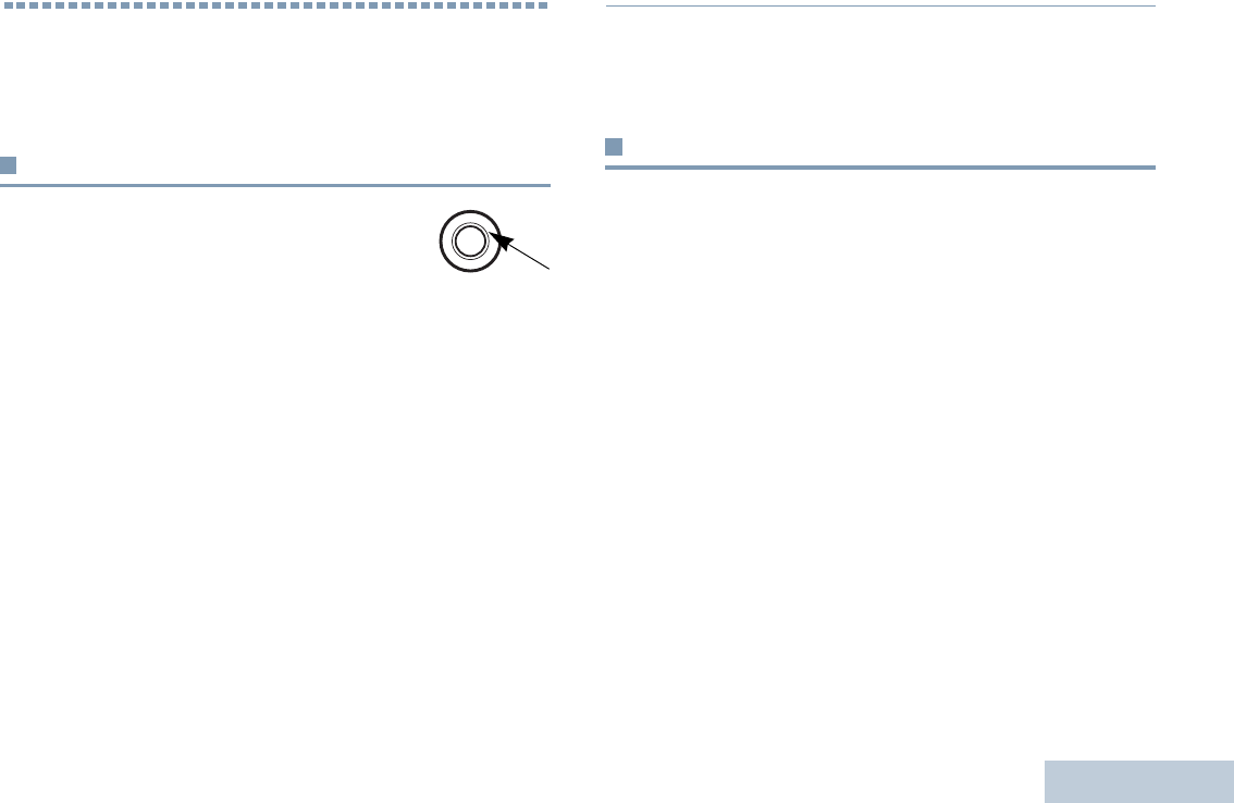
Accessories
English
71
Accessories
Your radio is compatible with the accessories listed in this
chapter. Contact your dealer for details.
Antennas
The diagram on the right shows the location of
the color indicator for the following antennas. See
the footnote at the end of the list for the colors.
•VHF, 136-155MHz, Helical Antenna (PMAD4117_)
•VHF, 144-165MHz, Helical Antenna (PMAD4116_)
•VHF, 152-174MHz, Helical Antenna (PMAD4118_)
•VHF, 136-148MHz, Stubby Antenna (PMAD4119_)
•VHF, 146-160MHz, Stubby Antenna (PMAD4120_)
•VHF, 160-174MHz, Stubby Antenna (PMAD4121_)
•UHF, 403-527MHz, Whip Antenna (PMAE4068_)
•UHF, 403-450MHz, Stubby Antenna (PMAE4069_)
•UHF, 440-490MHz, Stubby Antenna (PMAE4070_)
•UHF, 470-527MHz, Stubby Antenna (PMAE4071_)
Color Code:
Batteries
•Core NiMH, 1300mAH IP56 Battery (PMNN4415_)
•Core Slim Li-Ion, 1500mAH IP56 Battery (PMNN4417_)
•IMPRES Li-Ion Slim, 1500mAH IP56 Battery (PMNN4416_)
•IMPRES Li-Ion Non-FM, 2150mAH IP56 Battery
(PMNN4418_)
1. Red 3. Black 5. Blue 7. Brown 9. Purple
2. Green 4. Yellow 6. White 8. Orange 10.
LKP_NAG-LACR.book Page 71 Tuesday, September 6, 2011 5:01 PM

Accessories
English
72
Cables
•Programming Cable USB (PMKN4115_)
•Programming Cable Slim Connector to DB25 and TTR
(PMKN4116_)
•Programming Cable Slim Connector to DB25 and USB Plug
(PMKN4117_)
Carry Devices
•Hard Leather Carry Case with 3-Inch Fixed Belt Loop for
Limited Keypad Radio (PMLN5863_)
•Hard Leather Carry Case with 3-Inch Swivel Belt for Limited
Keypad Radio (PMLN5865_)
•Hard Leather Carry Case with 2.5-Inch Swivel Belt Loop for
Limited Keypad Radio (PMLN5867_)
•Nylon Carry Case with 3-Inch Fixed Belt Loop for Limited
Keypad Radio (PMLN5869_)
•Belt Clip for 2-Inch Belt Width (PMLN4651_)
•Belt Clip for 2.5-Inch Belt Width (PMLN7008_)
•2.5-Inch Replacement Leather Swivel Belt Loop
(PMLN5610_)
•3-Inch Replacement Leather Swivel Belt Loop (PMLN5611_)
Chargers
•IMPRES Single-Unit Charger, Base Only (WPLN4226_)
•IMPRES Single-Unit Charger (WPLN4255_)
•IMPRES Single-Unit Charger (WPLN4256_)
•IMPRES Multi-Unit Charger, Base Only (WPLN4211_)
•IMPRES Multi-Unit Charger, US/NA Plug (WPLN4212_)
•IMPRES Multi-Unit Charger, Euro Plug (WPLN4213_)
•IMPRES Multi-Unit Charger, UK Plug (WPLN4214_)
•IMPRES Multi-Unit Charger, Australia/NZ Plug (WPLN4215_)
•IMPRES Multi-Unit Charger, Korea Plug (WPLN4217_)
•IMPRES Multi-Unit Charger with Display Base Only
(WPLN4218_)
•IMPRES Multi-Unit Charger with Display, US/NA Plug
(WPLN4219_)
•IMPRES Multi-Unit Charger with Display, Euro Plug
(WPLN4220_)
•IMPRES Multi-Unit Charger with Display, UK Plug
(WPLN4221_)
•IMPRES Multi-Unit Charger with Display, Australia/NZ Plug
(WPLN4222_)
LKP_NAG-LACR.book Page 72 Tuesday, September 6, 2011 5:01 PM

Accessories
English
73
•IMPRES Multi-Unit Charger with Display, Korea Plug
(WPLN4224_)
•Core Single Unit Charger (NNTN8117_)
•Assembly, Accessory, LTD SUC IMPRESS SMPS Euro
(WPLN4255_)
•Assembly, Accessory, LTD SUC IMPRESS SMPS Aus/NZ
(WPLN4256_)
Earbuds and Earpieces
•Earbud with In-Line Mic/PTT, MagOne (PMLN5733_)
•Earpiece In-Line Mic/PTT Swivel, MagOne (PMLN5727_)
•Earset with Boom Microphone, MagOne (PMLN5732)
•Receive-Only Covered Earbud with Coiled Cord, for Remote
Speaker Microphone (AARLN4885_)
•Receive-Only Flexible Earpiece for Remote Speaker
Microphone (WADN4190_)
•D-Shell Receive Only Earpiece (One Size) for Remote
Speaker Microphone (PMLN4620_)
•Receiver-Only Earpiece with Translucent Tube and Rubber
Eartip for Remote Speaker Microphone (RLN4941_)
Headsets and Headset Accessories
•Heavy Duty Headset, Noise Cancelling with In-Line PTT
(PMLN5731_)
Remote Speaker Microphones
•IMPRES Remote Speaker Microphone Large, Noise
Cancelling with 3.5mm Jack (PMMN4071_)
•IMPRES Remote Speaker Microphone Small, with 3.5mm
Jack (PMMN4073_)
•Remote Speaker Microphone Small, No Emergency, IP57
(PMMN4075_)
•Remote Speaker Microphone Small with 3.5mm Jack
(PMMN4076_)
Surveillance Accessories
•2-Wire Surveillance Kit, Black (PMLN5724_)
•2-Wire Surveillance Kit, Beige (PMLN5726_)
LKP_NAG-LACR.book Page 73 Tuesday, September 6, 2011 5:01 PM

Accessories
English
74
Miscellaneous Accessories
•Adjustable Black Nylon Carrying Strap (Attaches to D-Ring on
Carry Case) (NTN5243_)
•Universal Chest Pack (HLN6602_)
•Break-A-Way Chest Pack with Radio Holder, Pen Holder and
Velcro Secured Pouch (RLN4570_)
•Replacement Strap for HLN6602A and RLN4570A
(1505596Z02)
•RadioPAK Radio Utility Case (Fanny Pack) (RLN4815_)
•RadioPAK Extension Belt (for Waists Larger than 40 Inch)
(4280384F89)
•Waterproof Bag with Large Strap (HLN9985_)
•Small Clip, Epaulet Strap (RLN4295_)
•1.75 Inch Wide Leather Belt (4200865599)
LKP_NAG-LACR.book Page 74 Tuesday, September 6, 2011 5:01 PM
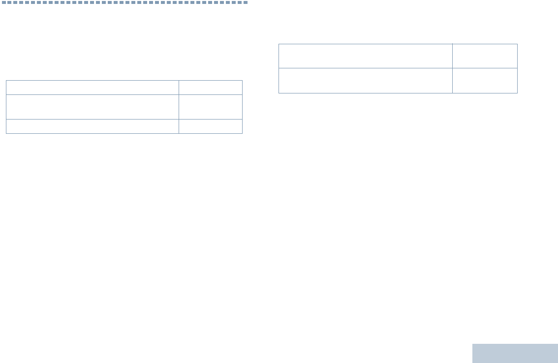
Batteries and Chargers Warranty
English
75
Batteries and Chargers Warranty
The Workmanship Warranty
The workmanship warranty guarantees against defects in
workmanship under normal use and service.
The Capacity Warranty
The capacity warranty guarantees 80% of the rated capacity for the
warranty duration.
All MOTOTRBO Batteries Two (2) Years
IMPRES Chargers (Single-Unit and Multi-Unit,
Non-Display) Two (2) Years
IMPRES Chargers (Multi-Unit with Display) One (1) Year
Nickel Metal-Hydride (NiMH) or Lithium-Ion
(Li-lon) Batteries 12 Months
IMPRES Batteries, When Used Exclusively
with IMPRES Chargers 18 Months
LKP_NAG-LACR.book Page 75 Tuesday, September 6, 2011 5:01 PM

Limited Warranty
English
76
Limited Warranty
MOTOROLA COMMUNICATION PRODUCTS
I. WHAT THIS WARRANTY COVERS AND FOR HOW
LONG:
MOTOROLA SOLUTIONS, INC. (“MOTOROLA”) warrants the
MOTOROLA manufactured Communication Products listed below
(“Product”) against defects in material and workmanship under
normal use and service for a period of time from the date of
purchase as scheduled below:
MOTOROLA, at its option, will at no charge either repair the
Product (with new or reconditioned parts), replace it (with a new or
reconditioned Product), or refund the purchase price of the Product
during the warranty period provided it is returned in accordance
with the terms of this warranty. Replaced parts or boards are
warranted for the balance of the original applicable warranty period.
All replaced parts of Product shall become the property of
MOTOROLA.
This express limited warranty is extended by MOTOROLA to the
original end user purchaser only and is not assignable or
transferable to any other party. This is the complete warranty for the
Product manufactured by MOTOROLA. MOTOROLA assumes no
obligations or liability for additions or modifications to this warranty
unless made in writing and signed by an officer of MOTOROLA.
Unless made in a separate agreement between MOTOROLA and
the original end user purchaser, MOTOROLA does not warrant the
installation, maintenance or service of the Product.
MOTOROLA cannot be responsible in any way for any ancillary
equipment not furnished by MOTOROLA which is attached to or
used in connection with the Product, or for operation of the Product
with any ancillary equipment, and all such equipment is expressly
excluded from this warranty. Because each system which may use
the Product is unique, MOTOROLA disclaims liability for range,
coverage, or operation of the system as a whole under this
warranty.
II. GENERAL PROVISIONS:
This warranty sets forth the full extent of MOTOROLA'S
responsibilities regarding the Product. Repair, replacement or
refund of the purchase price, at MOTOROLA’s option, is the
exclusive remedy. THIS WARRANTY IS GIVEN IN LIEU OF ALL
OTHER EXPRESS WARRANTIES. IMPLIED WARRANTIES,
INCLUDING WITHOUT LIMITATION, IMPLIED WARRANTIES OF
MERCHANTABILITY AND FITNESS FOR A PARTICULAR
PURPOSE, ARE LIMITED TO THE DURATION OF THIS LIMITED
WARRANTY. IN NO EVENT SHALL MOTOROLA BE LIABLE FOR
DAMAGES IN EXCESS OF THE PURCHASE PRICE OF THE
PRODUCT, FOR ANY LOSS OF USE, LOSS OF TIME,
INCONVENIENCE, COMMERCIAL LOSS, LOST PROFITS OR
SAVINGS OR OTHER INCIDENTAL, SPECIAL OR
CONSEQUENTIAL DAMAGES ARISING OUT OF THE USE OR
XPR Series Digital Portable Radios Two (2) Years
Product Accessories (Excluding
Batteries and Chargers) One (1) Year
LKP_NAG-LACR.book Page 76 Tuesday, September 6, 2011 5:01 PM

Limited Warranty
English
77
INABILITY TO USE SUCH PRODUCT, TO THE FULL EXTENT
SUCH MAY BE DISCLAIMED BY LAW.
III. STATE LAW RIGHTS:
SOME STATES DO NOT ALLOW THE EXCLUSION OR
LIMITATION OF INCIDENTAL OR CONSEQUENTIAL DAMAGES
OR LIMITATION ON HOW LONG AN IMPLIED WARRANTY
LASTS, SO THE ABOVE LIMITATION OR EXCLUSIONS MAY
NOT APPLY.
This warranty gives specific legal rights, and there may be other
rights which may vary from state to state.
IV. HOW TO GET WARRANTY SERVICE:
You must provide proof of purchase (bearing the date of purchase
and Product item serial number) in order to receive warranty
service and, also, deliver or send the Product item, transportation
and insurance prepaid, to an authorized warranty service location.
Warranty service will be provided by MOTOROLA through one of its
authorized warranty service locations. If you first contact the
company which sold you the Product (e.g., dealer or
communication service provider), it can facilitate your obtaining
warranty service. You can also call MOTOROLA at 1-800-927-2744
US/Canada.
V. WHAT THIS WARRANTY DOES NOT COVER:
A) Defects or damage resulting from use of the Product in other
than its normal and customary manner.
B) Defects or damage from misuse, accident, water, or neglect.
C)Defects or damage from improper testing, operation,
maintenance, installation, alteration, modification, or adjustment.
D)Breakage or damage to antennas unless caused directly by
defects in material workmanship.
E) A Product subjected to unauthorized Product modifications,
disassembles or repairs (including, without limitation, the addition
to the Product of non-MOTOROLA supplied equipment) which
adversely affect performance of the Product or interfere with
MOTOROLA's normal warranty inspection and testing of the
Product to verify any warranty claim.
F) Product which has had the serial number removed or made
illegible.
G)Rechargeable batteries if:
(1) any of the seals on the battery enclosure of cells are broken
or show evidence of tampering.
(2) the damage or defect is caused by charging or using the
battery in equipment or service other than the Product for which it
is specified.
H)Freight costs to the repair depot.
I) A Product which, due to illegal or unauthorized alteration of the
software/firmware in the Product, does not function in
accordance with MOTOROLA’s published specifications or the
FCC certification labeling in effect for the Product at the time the
Product was initially distributed from MOTOROLA.
J) Scratches or other cosmetic damage to Product surfaces that
does not affect the operation of the Product.
K) Normal and customary wear and tear.
LKP_NAG-LACR.book Page 77 Tuesday, September 6, 2011 5:01 PM

Limited Warranty
English
78
VI. PATENT AND SOFTWARE PROVISIONS:
MOTOROLA will defend, at its own expense, any suit brought
against the end user purchaser to the extent that it is based on a
claim that the Product or parts infringe a United States patent, and
MOTOROLA will pay those costs and damages finally awarded
against the end user purchaser in any such suit which are
attributable to any such claim, but such defense and payments are
conditioned on the following:
A) that MOTOROLA will be notified promptly in writing by such
purchaser of any notice of such claim;
B) that MOTOROLA will have sole control of the defense of such
suit and all negotiations for its settlement or compromise; and
C)should the Product or parts become, or in MOTOROLA’s opinion
be likely to become, the subject of a claim of infringement of a
United States patent, that such purchaser will permit
MOTOROLA, at its option and expense, either to procure for
such purchaser the right to continue using the Product or parts or
to replace or modify the same so that it becomes non-infringing
or to grant such purchaser a credit for the Product or parts as
depreciated and accept its return. The depreciation will be an
equal amount per year over the lifetime of the Product or parts as
established by MOTOROLA.
MOTOROLA will have no liability with respect to any claim of patent
infringement which is based upon the combination of the Product or
parts furnished hereunder with software, apparatus or devices not
furnished by MOTOROLA, nor will MOTOROLA have any liability
for the use of ancillary equipment or software not furnished by
MOTOROLA which is attached to or used in connection with the
Product. The foregoing states the entire liability of MOTOROLA
with respect to infringement of patents by the Product or any parts
thereof.
Laws in the United States and other countries preserve for
MOTOROLA certain exclusive rights for copyrighted MOTOROLA
software such as the exclusive rights to reproduce in copies and
distribute copies of such MOTOROLA software. MOTOROLA
software may be used in only the Product in which the software was
originally embodied and such software in such Product may not be
replaced, copied, distributed, modified in any way, or used to
produce any derivative thereof. No other use including, without
limitation, alteration, modification, reproduction, distribution, or
reverse engineering of such MOTOROLA software or exercise of
rights in such MOTOROLA software is permitted. No license is
granted by implication, estoppel or otherwise under MOTOROLA
patent rights or copyrights.
VII. GOVERNING LAW:
This Warranty is governed by the laws of the State of Illinois, U.S.A.
LKP_NAG-LACR.book Page 78 Tuesday, September 6, 2011 5:01 PM