Motorola Solutions 99FT4097 Non-Broadcast Transmitter User Manual Exhibit D Users Manual per 2 1033 c3
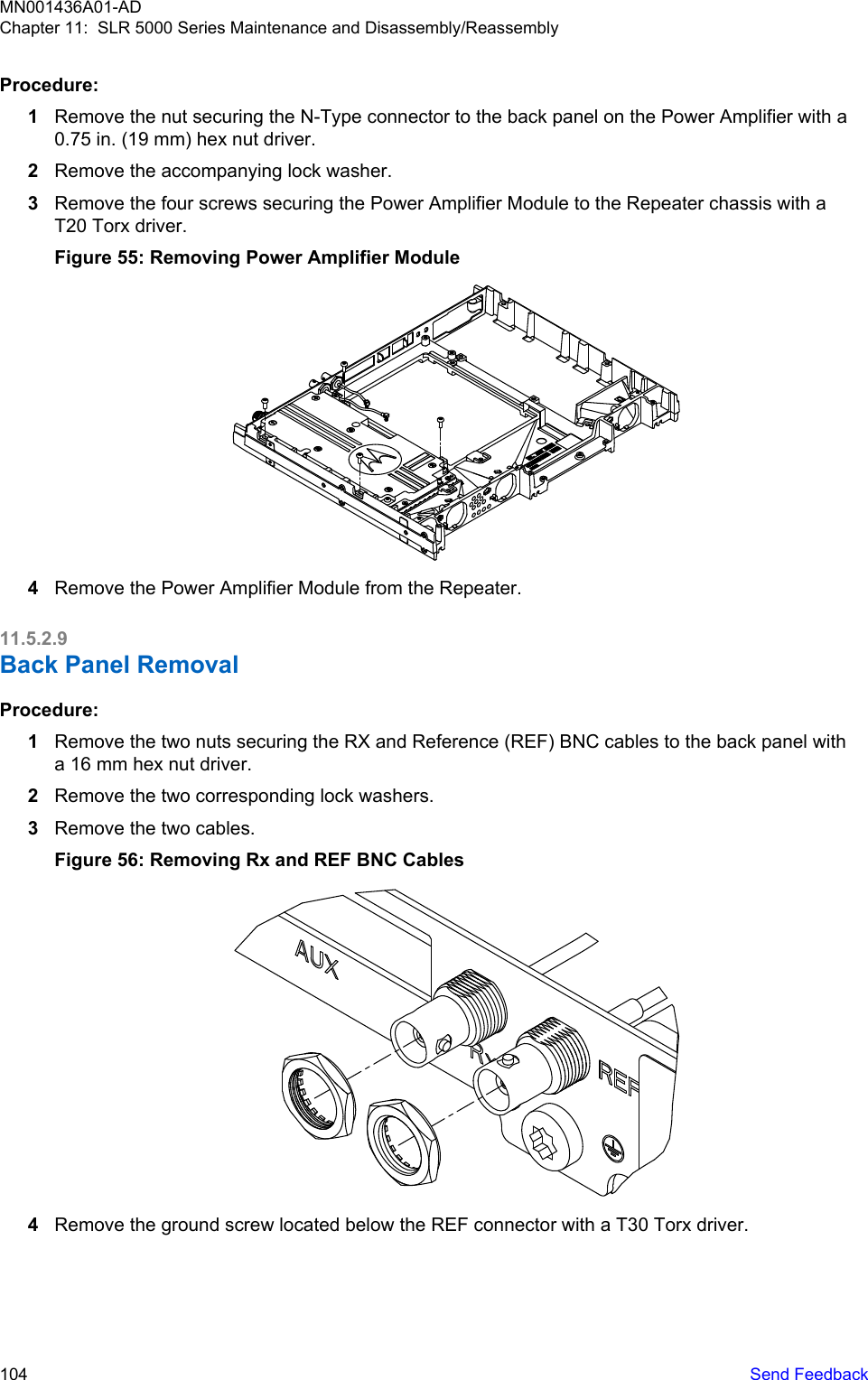
Motorola Solutions, Inc. Non-Broadcast Transmitter Exhibit D Users Manual per 2 1033 c3
UserManual.wiki
>
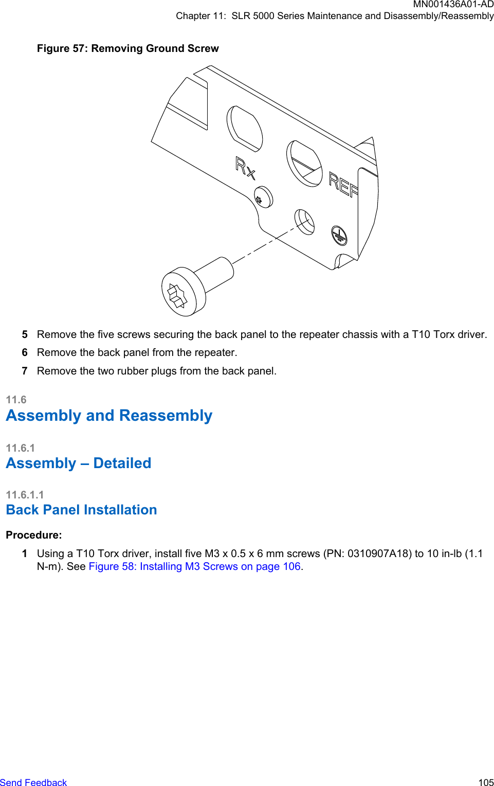
Motorola Solutions
>
99FT4097 User Manual
Exhibit D Users Manual per 2 1033 c3
Navigation menu
Upload a User Manual
Namespaces
Wiki Guide
HTML
PDF
Info
Views
User Manual
Discussion / Help
Navigation


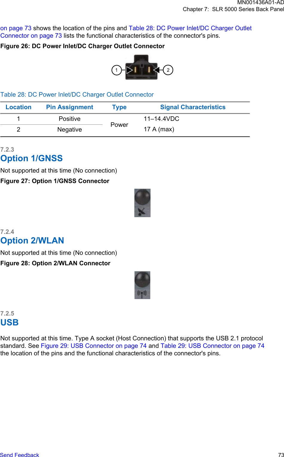


![CAUTION: This repeater contains static-sensitive devices. Do not open the repeater unless youare properly grounded. Take the following precautions when working on this unit:• Store and transport all CMOS/LDMOS devices in conductive material so that all exposedleads are shorted together. Do not insert CMOS/LDMOS devices into conventional plastic"snow" trays used for storage and transportation of other semiconductor devices.• Ground the working surface of the service bench to protect the CMOS/LDMOS device. Werecommend using the Motorola Solutions Static Protection Assembly (part number0180386A82), which includes a wrist strap, two ground cords, a table mat, and a floor mat,ESD shoes and an ESD chair.• Wear a conductive wrist strap in series with a 100k resistor to ground. (Replacement wriststraps that connect to the bench top covering are Motorola Solutions part number4280385A59).• Do not wear nylon clothing while handling CMOS/LDMOS devices.• Do not insert or remove CMOS/LDMOS devices with power applied. Check all powersupplies used for testing CMOS/LDMOS devices to be certain that there are no voltagetransients present.• When straightening CMOS/LDMOS pins, provide ground straps for the apparatus used.• When soldering, use a grounded soldering iron.• If at all possible, handle CMOS/LDMOS devices by the package and not by the leads. Priorto touching the unit, touch an electrical ground to remove any static charge that you mayhave accumulated. The package and substrate may be electrically common. If so, thereaction of a discharge to the case would cause the same damage as touching the leads.11.5Disassembly11.5.1Disassembly – GeneralStation modules suspected of being faulty must be replaced with known good modules to restore therepeater to proper operation. The following are typical procedures to remove each of the repeatermodules.Procedure:1Power cord (and battery backup power, if used) and all external cables must be disconnectedbefore opening up repeater. Label each removed cable as required to ensure it is properlyreconnected.2Take the proper grounding precautions as stated in Safe Handling of CMOS and LDMOSDevices on page 98.3When disassembling repeater, retain all screws for reuse.The following tools are required for disassembling and reassembling the repeater:• Torque Drivers (T10, T20 and T30). See Torque Charts on page 117 for the different sizefasteners of screw torques.• Hex Nut Drivers (16 mm, ¾ inch [19 mm])• Needle Nose Pliers (optional)• Torque Gauge capable of measuring torque up to 20 in-lb (2.3 N-m) within +/- 1 in-lb (0.1 N-m)MN001436A01-ADChapter 11: SLR 5000 Series Maintenance and Disassembly/ReassemblySend Feedback 99](https://usermanual.wiki/Motorola-Solutions/99FT4097/User-Guide-3459501-Page-99.png)