Motorola Solutions 99FT4097 Non-Broadcast Transmitter User Manual Exhibit D Users Manual per 2 1033 c3
Motorola Solutions, Inc. Non-Broadcast Transmitter Exhibit D Users Manual per 2 1033 c3
Exhibit D Users Manual per 2 1033 c3

SLR 5000 Series
Repeater Basic Service
& Installation Manual
MOTOTRBO™ REPEATER
PROFESSIONAL DIGITAL TWO-WAY RADIO SYSTEM
* MN001436A01*
MN001436A01-AD
JUNE 2017
© 2017 Motorola Solutions, Inc. All rights reserved

Notice
Foreword
This manual covers all versions of the MOTOTRBO SLR 5000 Series Repeater, unless otherwise
specified. It includes all the information necessary to maintain peak product performance and
maximum working time, using levels 1 and 2 maintenance procedures. These levels of service go
down to software issues or replacement of an accessory, which are commonly performed by local
service centers, Motorola Solutions Authorized Dealers, self-maintained customers, and distributors.
CAUTION: These servicing instructions are for use by qualified personnel only. To reduce the
risk of electric shock, do not perform any servicing other than that contained in the Operating
Instructions unless you are qualified to do so. Refer all servicing to qualified service personnel.
General Safety Precautions
For more information, see General Safety and Installation
Standards and Guidelines on page 5.
Computer Software Copyrights
The Motorola Solutions products described in this manual may include copyrighted Motorola Solutions
computer programs stored in semiconductor memories or other media. Laws in the United States and
other countries preserve for Motorola Solutions certain exclusive rights for copyrighted computer
programs, including, but not limited to, the exclusive right to copy or reproduce in any form the
copyrighted computer program. Accordingly, any copyrighted Motorola Solutions computer programs
contained in the Motorola Solutions products described in this manual may not be copied, reproduced,
modified, reverse-engineered, or distributed in any manner without the express written permission of
Motorola Solutions.
Furthermore, the purchase of Motorola Solutions products shall not be deemed to grant either directly
or by implication, estoppel, or otherwise, any license under the copyrights, patents or patent
applications of Motorola Solutions, except for the normal non-exclusive license to use that arises by
operation of law in the sale of a product.
Document Copyrights
No duplication or distribution of this document or any portion thereof shall take place without the
express written permission of Motorola Solutions.
No part of this manual may be reproduced, distributed, or transmitted in any form or by any means,
electronic or mechanical, for any purpose without the express written permission of Motorola Solutions.
Disclaimer
The information in this document is carefully examined, and is believed to be entirely reliable.
However, no responsibility is assumed for inaccuracies. Furthermore, Motorola Solutions reserves the
right to make changes to any products herein to improve readability, function, or design. Motorola
Solutions does not assume any liability arising out of the applications or use of any product or circuit
described herein; nor does it cover any license under its patent rights nor the rights of others.
Controlled copies of this document is available through Motorola Solutions On-Line (MOL).
MN001436A01-AD
Foreword
Send Feedback 3
Trademarks
MOTOROLA, MOTO, MOTOROLA SOLUTIONS and the Stylized M logo are trademarks or registered
trademarks of Motorola Trademark Holdings, LLC and are used under license. All other trademarks are
the property of their respective owners.
© 2017 Motorola Solutions, Inc.
All rights reserved.
MN001436A01-AD
Notice Foreword
4 Send Feedback

Notice
General Safety and Installation
Standards and Guidelines
WARNING:
• For safe installation, operation, service and repair of this equipment, follow the safety
precautions and instructions described below, as well as any additional safety information in
Motorola Solutions product service and installation manuals and the Motorola Solutions R56
Standards and Guidelines for Communications Sites manual (which can be obtained by
ordering CDROM 9880384V83). To obtain copies of these materials, please contact
Motorola Solutions as directed at the end of this section. After installation, these instructions
should be retained and readily available for any person operating or servicing this repeater
or working near it.
• Failure to follow these safety precautions and instructions could result in serious injury or
property damage.
• The installation process requires preparation and knowledge of the site before installation
begins. Review installation procedures and precautions in the Motorola Solutions R56
manual before performing any site or component installation. Personnel must use safe work
practices and good judgment, and always follow applicable safety procedures, such as
requirements of the Occupational Safety and Health Administration (OSHA), the National
Electrical Code (NEC), and local codes.
The following are additional general safety precautions that must be observed:
• To continue compliance with any applicable regulations and maintain the safety of this equipment,
do not install substitute parts or perform any unauthorized modifications.
• All equipment must be serviced by Motorola Solutions trained personnel.
• If troubleshooting the equipment while the power is on, be aware of live circuits which could contain
hazardous voltage.
• Do not operate the radio transmitters unless all RF connectors are secure and all connectors are
properly terminated.
• All equipment must be properly grounded in accordance with the Motorola Solutions R56 and
specified installation instructions for safe operation.
• Slots and openings in the cabinet are provided for ventilation. Do not block or cover openings that
protect the devices from overheating.
• Some equipment components can become extremely hot during operation. Turn off all power
to the equipment and wait until sufficiently cool before touching.
• Maintain emergency first aid kits at the site.
• Never store combustible materials in or near equipment racks. The combination of combustible
material, heat and electrical energy increases the risk of a fire hazard.
Equipment shall be installed in a site that meets the requirements of a
"restricted access location", per (UL60950-1 & EN60950-1), which is defined as follows: "Access
can only be gained by service persons or by users who have been instructed about the reasons for
the restrictions applied to the location and about any precautions that shall be taken; and access is
MN001436A01-AD
General Safety and Installation
Standards and Guidelines
Send Feedback 5

through the use of a tool or lock and key, or other means of security, and is controlled by the
authority responsible for the location."
• Burn hazard. The metal housing of the product may become extremely hot. Use caution
when working around the equipment.
• RF energy burn hazard. Disconnect power in the cabinet to prevent injury before
disconnecting and connecting antennas.
• Shock hazard. The outer shields of all Tx and Rx RF cables outer shields must be grounded per
Motorola Solutions R56 manual.
• Shock hazard. DC input voltage shall be no higher than 60 VDC. This maximum voltage shall
include consideration of the battery charging "float voltage" associated with the intended supply
system, regardless of the marked power rating of the equipment.
• All Tx and Rx RF cables shall be connected to a surge protection device according to Motorola
Solutions R56 manual. Do not connect Tx and Rx RF cables directly to an outside antenna.
•
Attention
Compliance with National and International standards and guidelines for human exposure to
Electromagnetic Energy (EME) at Transmitter Antenna sites generally requires that persons having
access to a site shall be aware of the potential for exposure to EME and can exercise control of
exposure by appropriate means, such as adhering to warning sign instructions. See this installation
manual and Appendix A of Motorola Solutions R56.
This product complies with the requirements set forth by the European R&TTE regulations and
applicable CENELEC standards concerning human exposure to Electromagnetic Energy (EME) at
Transmitter Antenna sites. Appendix F: MOTOTRBO Repeater – EME ASSESSMENT on page 155 in
this manual includes an EME exposure analysis of a typical system configuration for this product.
For a different system configuration than the typical configuration, compliance with applicable EME
exposure standards (current versions of the EN50384 and EN50385 standards for occupational and
general public exposure, respectively) can be evaluated by either employing the method illustrated in
the typical system configuration EME exposure analysis included in Appendix F: MOTOTRBO
Repeater – EME ASSESSMENT on page 155 in this manual, or employing another suitable method
among those described in the current version of the EN50383 standard.
Once the occupational and general public compliance boundaries are determined, means to ensure
that workers and people are outside the respective boundaries, for instance using appropriate signage
or restricted access, should be implemented; if this is not possible or practically achievable for the
specific system configuration, the configuration should be modified in order to make it possible. The
R56 Standards and Guidelines for Communications Sites manual (which can be obtained by ordering
CDROM 9880384V83) provides examples of signage that can be used to identify the occupational or
general public compliance boundaries.
Refer to product specific manuals for detailed safety and installation instructions. Manuals can be
obtained with product orders, downloaded from https://businessonline.motorolasolutions.com, or
purchased through the Motorola Solutions Aftermarket & Accessory Department.
WARNING: This is a class A product. In a domestic environment, this product may cause radio
interference in which case the user may be required to take adequate measures.
MN001436A01-AD
Notice General Safety and Installation
Standards and Guidelines
6 Send Feedback

Notice
MOTOTRBO SLR 5000 Series
Repeater
Supplemental Safety and Installation
Requirements
IMPORTANT:
• The MOTOTRBO SLR 5000 Series Repeater must be installed in a suitable, in-building
enclosure. A restricted access location is required when installing this equipment into the
end system.
• The repeater contains a Class 1 built-in power supply component. It is equipped with an
appliance inlet for connecting to an AC input, as well as DC input terminals which meet
SELV DC circuit requirements.
• When installing the equipment, all requirements of relevant standards and local electrical
codes must be fulfilled.
• The maximum operating ambient temperature of this equipment is 60 °C. The maximum
operating altitude is 2000 meters above sea level.
• The 13.6 VDC output from the power supply to the PA is at an energy hazard level (exceeds
240 VA). When installing into the end system, care must be taken so as not to touch the
output wires.
• When the SLR 5000 Series Repeater is used in a DC reverting system, the DC power
supply must be located in the same building as the MOTOTRBO SLR 5000 Series Repeater,
and it must meet the requirements of a SELV circuit.
MN001436A01-AD
MOTOTRBO SLR 5000 Series Repeater
Supplemental Safety and Installation Requirements
Send Feedback 7
This page intentionally left blank.

Notice
Environmental Information
Material Content
NOTICE:
• The Motorola Solutions MOTOTRBO SLR 5000 Series Repeater system and its subsystems
have been created in compliance with the environmental goals of the European Union's
Restriction of Hazardous Substances (RoHS 2) Directive 2011/65/EU and the Waste
Electrical and Electronic Equipment (WEEE) Directive 2012/19/EU as well as Motorola
Solutions corporate goals to minimize environmental impact of its products.
• This Motorola Solutions policy is reflected throughout the entire design, procurement,
assembly, and packaging process.
• In support of these efforts to provide environmentally-responsible products, please comply
with the information in the following sections regarding product disposal for systems being
replaced.
Disposal of your Electronic and Electric Equipment
Do not dispose of electronic and electric equipment or electronic and electric accessories with your
household waste. In some countries or regions, collection systems have been set up to handle waste
of electrical and electronic equipment.
In European Union countries, contact your local equipment supplier representative or service center for
information about the waste collection system in your country.
Disposal Guideline
The European Union's WEEE directive symbol on a Motorola Solutions product indicates that the
product should not be disposed of with household waste.
MN001436A01-AD
Environmental Information
Send Feedback 9
This page intentionally left blank.

Document History
The following major changes have been implemented in this manual since the previous edition:
Edition Description Date
MN001436A01-AA Initial Release April 2015
MN001436A01-AB Second Release. Added 350 – 400 MHz Bands August 2016
MN001436A01-AC Third Release. Removed PMHN4299 Chassis
Service Kit
February 2017
MN001436A01-AD Fourth Release. Added UHF R2, 450 – 527 MHz
Bands
June 2017
MN001436A01-AD
Document History
Send Feedback 11
This page intentionally left blank.
Contents
Document History..................................................................................................... 11
List of Figures............................................................................................................21
List of Tables............................................................................................................. 25
List of Procedures.....................................................................................................27
Related Publications.................................................................................................29
Summary of Bands Available...................................................................................31
Chapter 1: SLR 5000 Series Repeater..................................................................... 37
1.1 Notations Used in This Manual..............................................................................................37
1.2 Description.............................................................................................................................37
1.3 Operating Features................................................................................................................39
1.4 Frequency Ranges and Power Levels...................................................................................41
1.5 Specifications.........................................................................................................................41
1.6 Theory of Operation...............................................................................................................43
1.7 Basic Repeater Level Troubleshooting – RDAC and LEDs...................................................45
1.8 Repeater Model Numbering Scheme.................................................................................... 47
1.9 Model Chart........................................................................................................................... 47
1.9.1 VHF High Power...................................................................................................... 47
1.9.2 UHF R1 High Power................................................................................................ 48
1.9.3 UHF R2 High Power................................................................................................ 48
Chapter 2: SLR 5000 Series Satellite Receiver.......................................................49
2.1 Description.............................................................................................................................49
2.2 Operating Features................................................................................................................49
2.3 Frequency Ranges................................................................................................................ 49
2.4 Specifications.........................................................................................................................49
2.5 Configuration......................................................................................................................... 49
2.6 Basic Station Level Troubleshooting – RDAC and LEDs...................................................... 50
2.7 Model Chart........................................................................................................................... 50
Chapter 3: SLR 5000 Series Modem........................................................................51
3.1 Description.............................................................................................................................51
3.1.1 General Description................................................................................................. 51
3.1.2 Input and Output Connections................................................................................. 51
3.1.3 Frequency Bands.....................................................................................................53
3.2 Receiver Subsystem..............................................................................................................53
3.2.1 Specifications...........................................................................................................53
3.3 Transmitter Exciter Subsystem..............................................................................................54
MN001436A01-AD
Contents
Send Feedback 13
3.3.1 Specifications...........................................................................................................54
3.4 Station Control Subsystem.................................................................................................... 55
3.4.1 High Stability Reference Block.................................................................................55
3.4.2 Audio........................................................................................................................55
3.5 Station Control Interface........................................................................................................ 56
3.5.1 Front Panel Interface Connector..............................................................................56
3.5.2 Rear Panel Connections.......................................................................................... 56
3.5.3 Power Amplifier Interface Connector....................................................................... 56
3.5.4 Power Supply Interface Connector.......................................................................... 57
3.5.5 Expansion Board Interface Connector..................................................................... 57
3.5.6 Chassis ID Interface Connector............................................................................... 57
Chapter 4: SLR 5000 Series Power Amplifier......................................................... 59
4.1 Description.............................................................................................................................59
4.1.1 General Description................................................................................................. 59
4.2 Input and Output Connections............................................................................................... 59
4.3 Frequency Ranges................................................................................................................ 60
4.4 Specifications.........................................................................................................................60
4.5 Modem Interface....................................................................................................................61
Chapter 5: SLR 5000 Series Power Supply.............................................................63
5.1 Description.............................................................................................................................63
5.1.1 General Description................................................................................................. 63
5.2 Specifications.........................................................................................................................64
5.3 Power Supply Interface..........................................................................................................65
5.3.1 Power Source Inputs................................................................................................65
5.3.2 Power Supply Outputs............................................................................................. 66
5.3.3 Power Supply Digital Interface.................................................................................67
5.3.4 Power Supply Output Cable Signaling.....................................................................67
Chapter 6: SLR 5000 Series Front Panel.................................................................69
6.1 Description.............................................................................................................................69
6.1.1 General Description................................................................................................. 69
6.2 Input and Output Connections............................................................................................... 69
6.3 Interfaces............................................................................................................................... 70
6.3.1 Modem Interface...................................................................................................... 70
6.3.2 User/Service Interface............................................................................................. 70
6.3.2.1 USB............................................................................................................70
6.3.2.2 LED Indicators............................................................................................70
Chapter 7: SLR 5000 Series Back Panel................................................................. 71
7.1 Description.............................................................................................................................71
7.1.1 General Description................................................................................................. 71
MN001436A01-AD
Contents
14 Send Feedback
7.2 Back panel Interfaces............................................................................................................ 72
7.2.1 AC Power Inlet......................................................................................................... 72
7.2.2 DC Power Inlet/DC Charger Outlet.......................................................................... 72
7.2.3 Option 1/GNSS........................................................................................................ 73
7.2.4 Option 2/WLAN........................................................................................................ 73
7.2.5 USB..........................................................................................................................73
7.2.6 Ethernet 1................................................................................................................ 74
7.2.7 Ethernet 2................................................................................................................ 75
7.2.8 Auxiliary (Aux)..........................................................................................................75
7.2.9 Frequency Reference.............................................................................................. 78
7.2.10 Receiver RF........................................................................................................... 79
7.2.11 Transmitter RF....................................................................................................... 79
7.2.12 Bonding Ground Connection..................................................................................79
Chapter 8: SLR 5000 Series Test Equipment And Service Aids...........................81
8.1 Recommended Test Equipment............................................................................................ 81
8.2 Service Aids...........................................................................................................................81
Chapter 9: SLR 5000 Series Performance Check or Testing................................ 83
9.1 General.................................................................................................................................. 83
9.2 Transmitter Testing................................................................................................................83
9.2.1 Introduction.............................................................................................................. 83
9.2.2 Test Equipment........................................................................................................83
9.2.3 Verifying Transmitter Circuitry Procedure................................................................ 84
9.3 Receiver Testing....................................................................................................................85
9.3.1 Introduction.............................................................................................................. 85
9.3.2 Required Test Equipment........................................................................................ 85
9.3.3 Verifying Receiver Circuitry Procedure.................................................................... 86
9.4 Auto Test and Tune Support..................................................................................................87
Chapter 10: SLR 5000 Series Programming and Tuning.......................................89
10.1 Introduction.......................................................................................................................... 89
10.2 Customer Programming Software Setup............................................................................. 89
10.3 Reference Oscillator Alignment........................................................................................... 90
10.3.1 Tuning the Reference Oscillator Alignment........................................................... 90
10.4 Repeater Tuning Setup........................................................................................................91
10.5 Rx Audio Level Set.............................................................................................................. 91
10.5.1 Tuning the Rx Audio Level Set.............................................................................. 91
10.6 Tx Audio Level Set...............................................................................................................92
10.6.1 Tuning the Tx Audio Level Set...............................................................................92
10.7 Modulation Limit Alignment..................................................................................................93
10.7.1 Tuning the Modulation Limit (with no Tx Data and no PL)..................................... 93
MN001436A01-AD
Contents
Send Feedback 15
10.7.2 Verifiying the Modulation Limit (with no Tx Data and no PL)................................. 94
10.7.3 Tuning the Modulation Limit (with Tx Data or PL)..................................................95
10.7.4 Verifying the Modulation Limit (with Tx Data or PL)...............................................96
10.8 Changing to Battery Charger Only Mode.............................................................................96
Chapter 11: SLR 5000 Series Maintenance and Disassembly/Reassembly........ 97
11.1 Introduction.......................................................................................................................... 97
11.2 Routine Maintenance...........................................................................................................97
11.3 Preventive Maintenance...................................................................................................... 97
11.3.1 Inspection...............................................................................................................97
11.3.2 Cleaning Procedures............................................................................................. 97
11.4 Safe Handling of CMOS and LDMOS Devices....................................................................98
11.5 Disassembly........................................................................................................................ 99
11.5.1 Disassembly – General..........................................................................................99
11.5.2 Disassembly – Detailed....................................................................................... 100
11.5.2.1 Protective Cover Disassembly............................................................... 100
11.5.2.2 Front Housing Disassembly................................................................... 100
11.5.2.3 Cable Disassembly................................................................................ 100
11.5.2.4 Fan Disassembly....................................................................................101
11.5.2.5 Front Panel Disassembly....................................................................... 102
11.5.2.6 Power Supply Removal..........................................................................102
11.5.2.7 Modem Removal.................................................................................... 103
11.5.2.8 Power Amplifier Module Removal.......................................................... 103
11.5.2.9 Back Panel Removal..............................................................................104
11.6 Assembly and Reassembly............................................................................................... 105
11.6.1 Assembly – Detailed............................................................................................ 105
11.6.1.1 Back Panel Installation...........................................................................105
11.6.1.2 Input Cable Installation...........................................................................106
11.6.1.3 Power Amplifier Module Installation....................................................... 108
11.6.1.4 Modem Installation................................................................................. 108
11.6.1.5 Power Supply Installation.......................................................................110
11.6.1.6 Fan Installation.......................................................................................111
11.6.1.7 Front Panel Installation.......................................................................... 112
11.6.1.8 Cable Installation....................................................................................112
11.6.1.9 Front Housing Installation...................................................................... 114
11.6.1.10 Protective Cover Installation................................................................ 115
11.7 Exploded Mechanical View................................................................................................115
11.8 Parts List............................................................................................................................115
11.9 Torque Charts....................................................................................................................117
Chapter 12: SLR 5000 Series Installation............................................................. 119
MN001436A01-AD
Contents
16 Send Feedback
12.1 Pre-Installation Considerations..........................................................................................119
12.1.1 Installation Overview............................................................................................119
12.1.2 Site Environmental Conditions.............................................................................119
12.1.3 Equipment Ventilation.......................................................................................... 120
12.1.3.1 Mounting in a Cabinet............................................................................ 120
12.1.3.2 Mounting in a Rack................................................................................ 121
12.1.4 AC and DC Input Power Requirements............................................................... 121
12.1.4.1 AC Input Power Requirements...............................................................121
12.1.4.2 DC Input Power Requirements.............................................................. 121
12.1.4.3 Ground Connection................................................................................ 121
12.1.4.4 Battery Connection.................................................................................121
12.1.4.5 RF Antenna Connections....................................................................... 122
12.1.4.6 System Cable Connections....................................................................122
12.1.5 Equipment Mounting Methods............................................................................. 122
12.1.5.1 Floor-Mounted Cabinet.......................................................................... 122
12.1.5.2 Modular Racks....................................................................................... 123
12.1.5.3 Desk Mount............................................................................................ 124
12.1.6 Site Grounding and Lightning Protection............................................................. 124
12.1.6.1 Electrical Ground....................................................................................125
12.1.6.2 RF Ground............................................................................................. 125
12.1.6.3 Lightning Ground....................................................................................125
12.1.6.4 Equipment Grounding............................................................................ 125
12.1.7 Recommended Tools and Equipment..................................................................125
12.1.8 Equipment Unpacking and Inspection................................................................. 126
12.1.8.1 Unpack Equipment.................................................................................126
12.1.8.2 Initial Inspection..................................................................................... 126
12.2 Mechanical Installation...................................................................................................... 127
12.2.1 Mounting Procedures...........................................................................................127
12.2.1.1 Transferring Equipment from Shipping Container to Rack or Cabinet... 127
12.2.1.2 Installing Racks...................................................................................... 127
12.2.1.3 Cabinet Installation.................................................................................128
12.2.1.4 Desk Mount............................................................................................ 128
12.3 Electrical Connections....................................................................................................... 128
12.3.1 Power Supply Connections..................................................................................130
12.3.1.1 AC Input Power Connection...................................................................130
12.3.1.2 DC Input Power Connection/ DC Charger Connection.......................... 130
12.3.1.3 Ground Connection................................................................................ 130
12.3.1.4 Battery Connection.................................................................................130
12.3.1.5 RF Antenna Connections....................................................................... 131
MN001436A01-AD
Contents
Send Feedback 17
12.3.1.6 System Cable Connections....................................................................131
12.4 Post Installation Checklist..................................................................................................131
12.4.1 Apply Power.........................................................................................................131
12.4.2 Verify Proper Operation....................................................................................... 131
12.4.3 Front Panel LEDs.................................................................................................131
12.4.4 Repeater Codeplug Data Backup........................................................................ 132
12.5 Installing Repeater Hardware Options...............................................................................132
12.5.1 General Bonding and Grounding Requirements..................................................132
12.5.2 General Cabling Requirements............................................................................132
Appendix A: Accessories.......................................................................................133
Introduction................................................................................................................................ 133
Cables.............................................................................................................................133
Documentation................................................................................................................133
Duplexers........................................................................................................................133
Mounting......................................................................................................................... 134
Preselectors.................................................................................................................... 134
Service Parts...................................................................................................................134
Service Tools.................................................................................................................. 135
Appendix B: Replacement Parts Ordering........................................................... 137
Replacement Parts Ordering..................................................................................................... 137
Basic Ordering Information............................................................................................. 137
Motorola Solutions Online...............................................................................................137
Mail Orders..................................................................................................................... 137
Telephone Orders........................................................................................................... 137
Fax Orders...................................................................................................................... 138
Parts Identification.......................................................................................................... 138
Product Customer Service.............................................................................................. 138
Appendix C: Motorola Solutions Service Centers............................................... 139
Motorola Solutions Service Centers.......................................................................................... 139
Servicing Information...................................................................................................... 139
Motorola Solutions Service Center................................................................................. 139
Motorola Solutions Federal Technical Center.................................................................139
Motorola Canadian Technical Logistics Center.............................................................. 139
Appendix D: SLR 5000 Series Third-Party Controllers........................................141
Overview....................................................................................................................................141
Community Repeater Panel.......................................................................................................141
Compatibility................................................................................................................... 142
Hardware Connections................................................................................................... 142
CPS Configuration.......................................................................................................... 142
MN001436A01-AD
Contents
18 Send Feedback
Community Repeater Panel Settings..............................................................................144
Discriminator........................................................................................................ 144
Tx Audio............................................................................................................... 144
Continuous Tone-Controlled Squelch Systems (CTCSS) Out............................. 144
Tx Audio Pre-Emphasis....................................................................................... 145
Carrier Operated Relay (COR).............................................................................145
Phone Patch.............................................................................................................................. 145
Compatibility................................................................................................................... 145
Hardware Connections................................................................................................... 145
CPS Configuration.......................................................................................................... 146
Phone Patch Level Settings............................................................................................147
Disc...................................................................................................................... 147
Tx Audio............................................................................................................... 147
CTCSS/ DCS DECODE INPUT/ COR................................................................. 147
Tone Remote Adapter............................................................................................................... 148
Compatibility................................................................................................................... 148
Hardware Connections................................................................................................... 148
CPS Configuration (For a 15 Channel Remote Control).................................................149
Tone Remote Adapter Settings.......................................................................................151
Radio Rx.............................................................................................................. 151
Radio Tx...............................................................................................................151
Channel Steering................................................................................................. 151
Monitoring............................................................................................................ 151
PTT...................................................................................................................... 151
Wildcard 1 (optional)............................................................................................ 151
Trunking Controllers.................................................................................................................. 151
Compatibility................................................................................................................... 152
Hardware Connections................................................................................................... 152
CPS Configuration.......................................................................................................... 153
Trunking Controller Settings........................................................................................... 154
Discriminator........................................................................................................ 154
Tx Audio............................................................................................................... 154
Tx Data.................................................................................................................154
Appendix F: MOTOTRBO Repeater – EME ASSESSMENT..................................155
Executive Summary...................................................................................................................155
Indoor Exposure Prediction Model.............................................................................................156
Exposure in Front of the Antenna................................................................................... 156
Exposure at Ground Level.............................................................................................. 157
Typical System Configuration.................................................................................................... 158
MN001436A01-AD
Contents
Send Feedback 19
Exposure Limits......................................................................................................................... 158
EME Exposure Evaluation......................................................................................................... 159
Exposure in Front of the Antenna................................................................................... 159
Exposure at Ground Level.............................................................................................. 159
Compliance Boundary Description............................................................................................ 159
Product Put In Service............................................................................................................... 160
References................................................................................................................................ 160
Glossary of Terms and Acronyms.........................................................................163
MN001436A01-AD
Contents
20 Send Feedback
List of Figures
Figure 1: Front view of the SLR 5000 Series Repeater..........................................................................38
Figure 2: Rear view of the SLR 5000 Series Repeater.......................................................................... 38
Figure 3: Front view (without top cover) of the SLR 5000 Series Repeater........................................... 39
Figure 4: Front view (without top and bottom covers and front panel) of the SLR 5000 Series
Repeater............................................................................................................................................39
Figure 5: RDAC Diagnostic Screen........................................................................................................ 45
Figure 6: Repeater Model Numbering Scheme...................................................................................... 47
Figure 7: “Operation Mode” configuration for Satellite Receiver Functionality....................................... 50
Figure 8: Modem Module Connector Locations......................................................................................52
Figure 9: High Stability Reference Circuit...............................................................................................55
Figure 10: Audio Block Diagram.............................................................................................................56
Figure 11: Power Amplifier Interface Connector Pin Locations.............................................................. 56
Figure 12: Power Supply Interface Connector Pin Locations................................................................. 57
Figure 13: Expansion Board Interface Connector Pin Locations............................................................57
Figure 14: Chassis ID Interface Connector Pin Locations......................................................................58
Figure 15: Input and Output Connections...............................................................................................60
Figure 16: Modem Interface Connector Pin Locations........................................................................... 61
Figure 17: Front View of the SLR 5000 Series Power Supply................................................................64
Figure 18: Rear View of the SLR 5000 Series Power Supply................................................................ 64
Figure 19: Power Source Inputs............................................................................................................. 65
Figure 20: Power Supply Outputs...........................................................................................................66
Figure 21: Power Supply Digital Interface.............................................................................................. 67
Figure 22: Front Panel Input and Output Connections........................................................................... 69
Figure 23: Back Panel Connector Names and Locations.......................................................................71
Figure 24: AC Power Inlet Connector ....................................................................................................72
Figure 25: Repeater Power Switch.........................................................................................................72
Figure 26: DC Power Inlet/DC Charger Outlet Connector......................................................................73
Figure 27: Option 1/GNSS Connector.................................................................................................... 73
Figure 28: Option 2/WLAN Connector....................................................................................................73
Figure 29: USB Connector..................................................................................................................... 74
Figure 30: Ethernet 1 Connector............................................................................................................ 74
Figure 31: Ethernet 2 Connector............................................................................................................ 75
Figure 32: Auxiliary Connector............................................................................................................... 76
Figure 33: Frequency Reference Connector.......................................................................................... 78
Figure 34: Receiver RF Connector.........................................................................................................79
Figure 35: Transmitter RF Connector.....................................................................................................79
MN001436A01-AD
List of Figures
Send Feedback 21
Figure 36: Bonding Ground Connection................................................................................................. 79
Figure 37: Test Equipment Setup for Verifying Transmitter Circuitry..................................................... 85
Figure 38: Test Equipment Setup for Verifying Receiver Circuitry......................................................... 86
Figure 39: Customer Programming Software Setup...............................................................................89
Figure 40: Front view of SLR 5000 Series Repeater..............................................................................90
Figure 41: Rear view of SLR 5000 Series Repeater.............................................................................. 90
Figure 42: Tx Menu Tree (Ref. Oscillator).............................................................................................. 91
Figure 43: SLR 5000 Series Repeater Tuning Equipment Setup...........................................................91
Figure 44: Rx Menu tree (Rx Rated Volume)......................................................................................... 92
Figure 45: Auxiliary Connector............................................................................................................... 92
Figure 46: Tx Menu Tree (Tx Audio Level).............................................................................................93
Figure 47: TX Menu Tree (Tuning Procedure with No Tx Data).............................................................94
Figure 48: Example of Maximum Deviation Limit Calculation................................................................ 95
Figure 49: Removing Front Housing from Repeater.............................................................................100
Figure 50: Removing Cables................................................................................................................ 101
Figure 51: Removing Fan..................................................................................................................... 102
Figure 52: Removing Front Panel.........................................................................................................102
Figure 53: Removing Power Supply Module from Repeater................................................................ 103
Figure 54: Removing Modem............................................................................................................... 103
Figure 55: Removing Power Amplifier Module..................................................................................... 104
Figure 56: Removing Rx and REF BNC Cables...................................................................................104
Figure 57: Removing Ground Screw.................................................................................................... 105
Figure 58: Installing M3 Screws........................................................................................................... 106
Figure 59: Installing M6 Screw............................................................................................................. 106
Figure 60: Installing Rx and Reference Cables.................................................................................... 107
Figure 61: Assembling Lock Washers onto Connectors.......................................................................107
Figure 62: Installing WLAN and GNSS Rubber Plugs..........................................................................107
Figure 63: Installing Power Amplifier Module into Repeater.................................................................108
Figure 64: Securing Power Amplifier Module to Repeater Chassis......................................................108
Figure 65: Securing Modem to Repeater Frame.................................................................................. 109
Figure 66: Securing Rx and Reference Cable Connectors.................................................................. 109
Figure 67: Modem FRU Product Label.................................................................................................110
Figure 68: Installing Power Supply Module.......................................................................................... 110
Figure 69: Installing M4 Screws........................................................................................................... 111
Figure 70: Snapping Fan Cable............................................................................................................111
Figure 71: Installing Fan....................................................................................................................... 112
Figure 72: Installing Front Panel...........................................................................................................112
Figure 73: Installing Power Screws...................................................................................................... 113
Figure 74: Securing Cables.................................................................................................................. 113
MN001436A01-AD
List of Figures
22 Send Feedback
Figure 75: Securing Front Housing.......................................................................................................114
Figure 76: Installing M3 Screws........................................................................................................... 115
Figure 77: SLR 5000 Series Assembly Exploded View........................................................................115
Figure 78: Floor Mount Cabinet............................................................................................................123
Figure 79: Modular Rack...................................................................................................................... 124
Figure 80: Desk Mount Installation....................................................................................................... 128
Figure 81: Back Panel Connector Names and Locations.....................................................................129
Figure 82: Location of USB Connector.................................................................................................129
Figure 83: CPS Settings to Configure SLR 5000 Series Repeater for Analog Mode........................... 141
Figure 84: Model Zetron 38 Repeater Panel........................................................................................ 141
Figure 85: Signal Connections between SLR 5000 Series Repeater and Community Repeater
Panel............................................................................................................................................... 142
Figure 86: CPS Configuration for Community Repeater Panel (1 of 2)................................................143
Figure 87: CPS Configuration for Community Repeater Panel (2 of 2)................................................144
Figure 88: Zetron Model 30 Phone Patch.............................................................................................145
Figure 89: Signal Connections between SLR 5000 Series Repeater and Zetron Model 30 Phone
Patch (Analog Phone Patch Cable & Digital Phone Patch Cable).................................................. 146
Figure 90: CPS Configuration for Phone Patch (1 of 2)....................................................................... 147
Figure 91: CPS Configuration for Phone Patch (2 of 2)....................................................................... 147
Figure 92: Model L3276 Tone Remote Adapter................................................................................... 148
Figure 93: Signal Connections between SLR 5000 Series Repeater and Motorola Solutions L3276
25-Pin connector for a 15 Channel Remote Control........................................................................149
Figure 94: CPS Configuration for L3276 Tone Remote Adapter
(For a 15 Channel Remote Control)................................................................................................ 150
Figure 95: Model Trident’s Marauder................................................................................................... 151
Figure 96: Model Trident’s Raider........................................................................................................ 152
Figure 97: Model Trident’s NTS............................................................................................................152
Figure 98: Signal connections between SLR 5000 Series Repeater, Trident Model Raider,
Marauder, and NTS......................................................................................................................... 153
Figure 99: CPS Configuration for Trident Model Raider, Marauder and NTS...................................... 154
Figure 100: Reference Frame for the Point of Interest (POI) Cylindrical Co-Ordinates....................... 156
Figure 101: Schematic of the Ground-Level Exposure Model Adopted for the Assessment................158
Figure 102: Compliance Boundary for General Public (GP) and Ocupational (OCC) Exposure..........160
MN001436A01-AD
List of Figures
Send Feedback 23
This page intentionally left blank.
List of Tables
Table 1: Callout Legend......................................................................................................................... 38
Table 2: Callout Legend......................................................................................................................... 38
Table 3: Callout Legend......................................................................................................................... 39
Table 4: Callout Legend......................................................................................................................... 39
Table 5: SLR 5000 Series Frequency Ranges and Power Levels......................................................... 41
Table 6: SLR 5000 Series Repeater General Specifications (All Bands)............................................... 41
Table 7: SLR 5000 Series Repeater Specifications............................................................................... 42
Table 8: Front Panel LED indicators.......................................................................................................45
Table 9: SLR 5000 Series Front Panel LED Definitions......................................................................... 46
Table 10: Callout Legend....................................................................................................................... 52
Table 11: Specifications of Receiver Subsystem................................................................................... 53
Table 12: Specifications of Transmitter Exciter Subsystem................................................................... 54
Table 13: Callout Legend....................................................................................................................... 60
Table 14: Specifications of Power Amplifier........................................................................................... 60
Table 15: Callout Legend....................................................................................................................... 64
Table 16: Callout Legend....................................................................................................................... 64
Table 17: Power Supply AC Performance Specifications.......................................................................64
Table 18: Power Supply DC Performance Specifications...................................................................... 64
Table 19: Power Supply Battery Charger Performance Specifications.................................................. 65
Table 20: Callout Legend....................................................................................................................... 65
Table 21: Callout Legend ...................................................................................................................... 66
Table 22: Callout Legend....................................................................................................................... 67
Table 23: Power Supply Output Cable SIgnalling.................................................................................. 67
Table 24: Callout Legend....................................................................................................................... 69
Table 25: Connector Type and Primary Function...................................................................................71
Table 26: AC Power Inlet Connector...................................................................................................... 72
Table 27: Callout Legend....................................................................................................................... 72
Table 28: DC Power Inlet/DC Charger Outlet Connector....................................................................... 73
Table 29: USB Connector.......................................................................................................................74
Table 30: Ethernet 1 Connector............................................................................................................. 74
Table 31: Ethernet 2 Connector............................................................................................................. 75
Table 32: Auxiliary Connector................................................................................................................ 76
Table 33: Frequency Reference............................................................................................................. 78
Table 34: Recommended Test Equipment............................................................................................. 81
Table 35: Callout Legend....................................................................................................................... 90
Table 36: Callout Legend....................................................................................................................... 90
MN001436A01-AD
List of Tables
Send Feedback 25
Table 37: SLR 5000 Series Exploded View Parts List..........................................................................115
Table 38: Torque Specifications for Nuts and Screws..........................................................................117
Table 39: Cabinet Models.....................................................................................................................122
Table 40: Cabinet Slide........................................................................................................................ 123
Table 41: Rack Models.........................................................................................................................123
Table 42: Connector Type and Primary Function.................................................................................129
Table 43: Callout Legend..................................................................................................................... 130
Table 44: EME Compliance Distances Based on Example UHF Evaluation........................................155
MN001436A01-AD
List of Tables
26 Send Feedback
List of Procedures
Verifying Transmitter Circuitry Procedure ..............................................................................................84
Verifying Receiver Circuitry Procedure ..................................................................................................86
Tuning the Reference Oscillator Alignment ........................................................................................... 90
Tuning the Rx Audio Level Set .............................................................................................................. 91
Tuning the Tx Audio Level Set .............................................................................................................. 92
Tuning the Modulation Limit (with no Tx Data and no PL) .....................................................................93
Verifiying the Modulation Limit (with no Tx Data and no PL) .................................................................94
Tuning the Modulation Limit (with Tx Data or PL) ................................................................................. 95
Changing to Battery Charger Only Mode .............................................................................................. 96
Disassembly – General ......................................................................................................................... 99
Protective Cover Disassembly .............................................................................................................100
Front Housing Disassembly .................................................................................................................100
Cable Disassembly ..............................................................................................................................100
Fan Disassembly ................................................................................................................................. 101
Front Panel Disassembly .....................................................................................................................102
Power Supply Removal ....................................................................................................................... 102
Modem Removal ................................................................................................................................. 103
Power Amplifier Module Removal ....................................................................................................... 103
Back Panel Removal ........................................................................................................................... 104
Back Panel Installation ........................................................................................................................ 105
Input Cable Installation ........................................................................................................................ 106
Power Amplifier Module Installation .................................................................................................... 108
Modem Installation .............................................................................................................................. 108
Power Supply Installation .................................................................................................................... 110
Fan Installation .................................................................................................................................... 111
Front Panel Installation ........................................................................................................................112
Cable Installation ................................................................................................................................. 112
Front Housing Installation ....................................................................................................................114
Protective Cover Installation ................................................................................................................115
Installing Racks ................................................................................................................................... 127
MN001436A01-AD
List of Procedures
Send Feedback 27
This page intentionally left blank.

This page intentionally left blank.

Summary of Bands Available
Table below lists the SLR 5000 Series Repeater bands available in this manual. For details, see Model
Charts section.
Frequency Band Bandwidth Power Level
VHF 136–174 MHz 1–50 W
UHF R1 400–470 MHz 1–50 W
UHF R2 450–527 MHz 1–50 W
MN001436A01-AD
Summary of Bands Available
Send Feedback 31
This page intentionally left blank.

Notice
Commercial Warranty
Limited Warranty
MOTOROLA COMMUNICATION PRODUCTS
I. What This Warranty Covers And For How Long
MOTOROLA SOLUTIONS INC. (“MOTOROLA”) warrants the MOTOROLA manufactured
Communication Products listed below (“Product”) against defects in material and workmanship under
normal use and service for a period of time from the date of purchase as scheduled below:
Repeater Two (2) Years
Product Accessories One (1) Year
Motorola, at its option, will at no charge either repair the Product (with new or reconditioned parts),
replace it (with a new or reconditioned Product), or refund the purchase price of the Product during the
warranty period provided it is returned in accordance with the terms of this warranty. Replaced parts or
boards are warranted for the balance of the original applicable warranty period. All replaced parts of
Product shall become the property of MOTOROLA.
This express limited warranty is extended by MOTOROLA to the original end user purchaser only and
is not assignable or transferable to any other party. This is the complete warranty for the Product
manufactured by MOTOROLA. MOTOROLA assumes no obligations or liability for additions or
modifications to this warranty unless made in writing and signed by an officer of MOTOROLA. Unless
made in a separate agreement between MOTOROLA and the original end user purchaser,
MOTOROLA does not warrant the installation, maintenance or service of the Product.
MOTOROLA cannot be responsible in any way for any ancillary equipment not furnished by
MOTOROLA which is attached to or used in connection with the Product, or for operation of the
Product with any ancillary equipment, and all such equipment is expressly excluded from this warranty.
Because each system which may use the Product is unique, MOTOROLA disclaims liability for range,
coverage, or operation of the system as a whole under this warranty.
II. General Provisions
This warranty sets forth the full extent of MOTOROLA's responsibilities regarding the Product. Repair,
replacement or refund of the purchase price, at MOTOROLA's option, is the exclusive remedy. THIS
WARRANTY IS GIVEN IN LIEU OF ALL OTHER EXPRESS WARRANTIES. IMPLIED WARRANTIES,
INCLUDING WITHOUT LIMITATION, IMPLIED WARRANTIES OF MERCHANTABILITY AND
FITNESS FOR A PARTICULAR PURPOSE, ARE LIMITED TO THE DURATION OF THIS LIMITED
WARRANTY. IN NO EVENT SHALL MOTOROLA BE LIABLE FOR DAMAGES IN EXCESS OF THE
PURCHASE PRICE OF THE PRODUCT, FOR ANY LOSS OF USE, LOSS OF TIME,
INCONVENIENCE, COMMERCIAL LOSS, LOST PROFITS OR SAVINGS OR OTHER INCIDENTAL,
SPECIAL OR CONSEQUENTIAL DAMAGES ARISING OUT OF THE USE OR INABILITY TO USE
SUCH PRODUCT, TO THE FULL EXTENT SUCH MAY BE DISCLAIMED BY LAW.
III. State Law Rights
SOME STATES DO NOT ALLOW THE EXCLUSION OR LIMITATION OF INCIDENTAL OR
CONSEQUENTIAL DAMAGES OR LIMITATION ON HOW LONG AN IMPLIED WARRANTY LASTS,
SO THE ABOVE LIMITATION OR EXCLUSIONS MAY NOT APPLY.
MN001436A01-AD
Commercial Warranty
Send Feedback 33
This warranty gives specific legal rights, and there may be other rights which may vary from state to
state
IV. How To Get Warranty Service
You must provide proof of purchase (bearing the date of purchase and Product item serial number) in
order to receive warranty service and, also, deliver or send the Product item, transportation and
insurance prepaid, to an authorized warranty service location. Warranty service will be provided by
Motorola through one of its authorized warranty service locations. If you first contact the company
which sold you the Product, it can facilitate your obtaining warranty service. You can also .
V. What This Warranty Does Not Cover
Defects or damage resulting from use of the Product in other than its normal and customary manner.
Defects or damage from misuse, accident, water, or neglect.
Defects or damage from improper testing, operation, maintenance, installation, alteration, modification,
or adjustment.
Breakage or damage to antennas unless caused directly by defects in material workmanship.
A Product subjected to unauthorized Product modifications, disassemblies or repairs (including, without
limitation, the addition to the Product of non-Motorola supplied equipment) which adversely affect
performance of the Product or interfere with Motorola's normal warranty inspection and testing of the
Product to verify any warranty claim.
Product which has had the serial number removed or made illegible.
Freight costs to the repair depot.
A Product which, due to illegal or unauthorized alteration of the software/firmware in the Product, does
not function in accordance with MOTOROLA’s published specifications or the FCC type acceptance
labeling in effect for the Product at the time the Product was initially distributed from MOTOROLA.
Scratches or other cosmetic damage to Product surfaces that does not affect the operation of the
Product.
Normal and customary wear and tear.
VI. Patent And Software Provisions
MOTOROLA will defend, at its own expense, any suit brought against the end user purchaser to the
extent that it is based on a claim that the Product or parts infringe a United States patent, and
MOTOROLA will pay those costs and damages finally awarded against the end user purchaser in any
such suit which are attributable to any such claim, but such defense and payments are conditioned on
the following:
that MOTOROLA will be notified promptly in writing by such purchaser of any notice of such claim;
that MOTOROLA will have sole control of the defense of such suit and all negotiations for its
settlement or compromise; and
should the Product or parts become, or in MOTOROLA's opinion be likely to become, the subject of a
claim of infringement of a United States patent, that such purchaser will permit MOTOROLA, at its
option and expense, either to procure for such purchaser the right to continue using the Product or
parts or to replace or modify the same so that it becomes noninfringing or to grant such purchaser a
credit for the Product or parts as depreciated and accept its return. The depreciation will be an equal
amount per year over the lifetime of the Product or parts as established by MOTOROLA.
MOTOROLA will have no liability with respect to any claim of patent infringement which is based upon
the combination of the Product or parts furnished hereunder with software, apparatus or devices not
furnished by MOTOROLA, nor will MOTOROLA have any liability for the use of ancillary equipment or
software not furnished by MOTOROLA which is attached to or used in connection with the Product.
The foregoing states the entire liability of MOTOROLA with respect to infringement of patents by the
Product or any parts thereof.
MN001436A01-AD
Notice Commercial Warranty
34 Send Feedback
Laws in the United States and other countries preserve for MOTOROLA certain exclusive rights for
copyrighted MOTOROLA software such as the exclusive rights to reproduce in copies and distribute
copies of such Motorola software. MOTOROLA software may be used in only the Product in which the
software was originally embodied and such software in such Product may not be replaced, copied,
distributed, modified in any way, or used to produce any derivative thereof. No other use including,
without limitation, alteration, modification, reproduction, distribution, or reverse engineering of such
MOTOROLA software or exercise of rights in such MOTOROLA software is permitted. No license is
granted by implication, estoppel or otherwise under MOTOROLA patent rights or copyrights.
VII. Governing Law
This Warranty is governed by the laws of the State of Illinois, USA.
MN001436A01-AD
Notice Commercial Warranty
Send Feedback 35
This page intentionally left blank.
Chapter 1
SLR 5000 Series Repeater
1.1
Notations Used in This Manual
Throughout the text in this publication, there are WARNING, CAUTION, and Note notations. These
notations are used to emphasize that safety hazards exist, and due care must be taken and observed.
NOTICE: An operational procedure, practice, or condition which is essential to emphasize.
CAUTION: CAUTION indicates a potentially hazardous situation which, if not avoided, might
result in equipment damage.
WARNING: WARNING indicates a potentially hazardous situation which, if not avoided, could
result in death or injury.
Symbol indicates areas of the product that pose potential burn hazards.
1.2
Description
The Motorola Solutions SLR 5000 Series Repeater provides a modular, flexible analog and digital
station designed for today's communication systems and for the future.
The station is available for use in these configurations:
• Analog Conventional
• Digital (MOTOTRBO)
- MOTOTRBO DMR Tier 2 Conventional – Single Site
- MOTOTRBO DMR Tier 2 Conventional – IP Site Connect
- MOTOTRBO Capacity Plus Trunking
- MOTOTRBO Connect Plus Trunking
- MOTOTRBO Digital Voting
• LTR Trunking
• Passport Trunking
• MPT1327 Trunking
NOTICE: Certain software features enabled through the CPS can be configured with the Online
Help or with a regional representative. Refer to the regional Ordering Guide to determine the
features available within the respective regions.
The SLR 5000 series can either be configured as a stand-alone repeater or as a repeater connected to
a back-end network, as in the case of operating in IP Site Connect mode. As a repeater, it listens on
one uplink frequency, and then re-transmits on a downlink frequency, thus providing the RF interface to
the field subscribers. When configured for analog station operation, the repeater is designed to operate
with most existing analog systems, which enables a smooth migration to the MOTOTRBO system.
When configured for digital operation, the repeater offers additional services. The digital repeater
operates in TDMA mode, which essentially divides one channel into two virtual channels using time
MN001436A01-AD
SLR 5000 Series Repeater
Send Feedback 37

slots; therefore the user capacity is doubled. The repeater utilizes embedded signaling to inform the
field radios of the busy/idle status of each channel (time slot), the type of traffic, and even the source
and destination information.
The SLR 5000 series facilitates the field replaceable unit (FRU) concept of field repair to maximize
system uptime. The FRU concept also aids in allowing the end user/maintainer to lower their inventory
costs. The base model SLR 5000 series FRUs are as follows:
• Modem FRU
• Power Amplifier FRU
• Power Supply FRU
• Front Panel FRU
See Figure 1: Front view of the SLR 5000 Series Repeater on page 38 for the front view and Figure
2: Rear view of the SLR 5000 Series Repeater on page 38 for the rear view of SLR 5000 series
repeater. Figure 3: Front view (without top cover) of the SLR 5000 Series Repeater on page 39
shows the front view portion of the repeater without the top cover and Figure 4: Front view (without top
and bottom covers and front panel) of the SLR 5000 Series Repeater on page 39 shows the front
view portion of the repeater without the top cover, bottom cover, and front panel.
Figure 1: Front view of the SLR 5000 Series Repeater
2
1
Table 1: Callout Legend
Label Description
1 Front Panel LED Indicators
2 USB Port
Figure 2: Rear view of the SLR 5000 Series Repeater
1
Table 2: Callout Legend
Label Description
1 Back Panel Interface Connectors and Power Switch
MN001436A01-AD
Chapter 1: SLR 5000 Series Repeater
38 Send Feedback
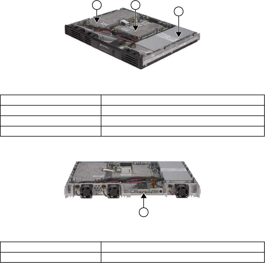
Figure 3: Front view (without top cover) of the SLR 5000 Series Repeater
1 2
3
Table 3: Callout Legend
Label Description
1 Power Amplifier Module
2 Modem Module
3 Power Supply Module
Figure 4: Front view (without top and bottom covers and front panel) of the SLR 5000 Series
Repeater
1
Table 4: Callout Legend
Label Description
1 Front Panel Board
1.3
Operating Features
The following are the standard features of an SLR 5000 series model:
• MOTOTRBO Conventional Operation (2-Slot TDMA, 4FSK Modulation)
• Analog Conventional Operation (FM)
• Continuous Duty Cycle Operation over -30 °C to +60 °C
• Meets or exceeds the following standards:
- TIA603D
- ETSI EN 300 086
- ETSI EN 300 113
MN001436A01-AD
Chapter 1: SLR 5000 Series Repeater
Send Feedback 39

- ETSI TS 102 361-1 Part 1: DMR Air Interface Protocol
- ETSI TS 102 361-2 Part 2: DMR Voice and Generic Services and Facilities
- ETSI TS 102 361-3 Part 3: DMR Packet Data Protocol
- ETSI TS 102 361-4 Part 4: DMR Trunking Protocol
- California Energy Commission (CEC) - Compliant to Title 20 Appliance Efficiency Regulations
when operated in Battery Charger Only mode with Sprinter Battery S12V370. Charge time may
take up to 40 hr.
• AMBE +2™ Digital VOCODER
• Synthesized Frequency Generation
• Female N-type Antenna Connector (Tx)
• Female BNC Antenna Connector (Rx)
• Ethernet Port (Network)
• Front-mounted USB Port (Service)
• 12 configurable GPIO ports (Digital)
• 4 configurable GPI ports (Analog)
• 2 configurable GPO ports (Analog)
• Power for third-party controllers (1 A)
• 1.5 PPM Frequency Stability (Temperature and 1-Year Aging) (VHF and UHF)
• External Reference Capability
• Switching Power Supply operates from 85–264 VAC (47–63 Hz)
• Multi-Power Source configurable (AC, DC, or AC with Battery Revert)
• Integrated 3 A battery charger
• Station Diagnostic Tests – Fixed Set of Tests run upon Start-up
• Physical Dimensions: 1.75 in. H x 19 in. W x 14.6 in. D (44 x 483 x 370 mm) 1RU
• Weight: 19 lb (8.62 kg) excluding cabinet or other peripheral equipment
Motorola Solutions Network Interface:
• IP Site Connect
• Repeater Diagnostics and Control (RDAC)
• Capacity Plus
• Connect Plus
Third-Party Controller Interface:
• Phone Patch
• Multi-Coded Squelch Interface (Repeater Panel)
• Tone Remote Adapter
• LTR Trunking
• Passport Trunking
• MPT1327 Trunking
NOTICE: The SLR 5000 series repeater only supports the third-party controllers noted above
when it is configured in analog mode. The exception is phone patch in digital mode.
MN001436A01-AD
Chapter 1: SLR 5000 Series Repeater
40 Send Feedback

In addition, the following features are also included. These features are shipped in a preset condition,
but may be altered through the use of the CPS.
• 64 Tx/Rx Frequencies – Factory Programmed with 1 Tx, 1 Rx
• 12.5 kHz or 25 kHz Operation – Factory Programmed to 12.5 kHz
• 1 Tx and 1 Rx (PL or DPL) Squelch Code per channel – Factory Programmed to CSQ
• Base Station Identification (BSI) – Factory Programmed as "BLANK" ("BLANK" disables BSI)
• Push-To-Talk (PTT) Priority – Factory Programmed to Repeat Path
1.4
Frequency Ranges and Power Levels
The SLR 5000 Series Repeater is available in the following frequency ranges and power levels table.
Table 5: SLR 5000 Series Frequency Ranges and Power Levels
Frequency Band Bandwidth Power Level
VHF 136–174 MHz 1–25 W
1–50 W
UHF R1 400–470 MHz 1–25 W
1–50 W
UHF R2 450–527 MHz 1–50 W
1.5
Specifications
Specifications of the SLR 5000 series repeater are available in the following tables.
Table 6: SLR 5000 Series Repeater General Specifications (All Bands)
Parameter Specifications
Number of Channels 64
Frequency Generation Synthesized
Input Voltage AC 100–240 VAC (47–63 Hz)
Input Voltage DC 11.0–14.4 VDC
Power Supply Type Switching
Station Weight 19 lbs (8.62 kg)
Temperature Range -30 °C to +60 °C (-22 °F to +140 °F)
Humidity Range RH of 95%, non-condensing at 50 °C (122 °F)
Antenna Connectors Tx: N-Type, Rx: BNC
Modes of Operation Half-Duplex/Duplex
Rack Unit 1
Height 1.75 in. (44 mm)
Width 19 in. (483 mm)
Depth 14.6 in. (370 mm)
MN001436A01-AD
Chapter 1: SLR 5000 Series Repeater
Send Feedback 41

Table 7: SLR 5000 Series Repeater Specifications
Parameter Specifications
VHF UHF
Input Power (All Modulations)
Standby (AC Line 117 V/220 V) 0.18 A/0.25 A
50 W Transmit at Rated Power
(AC Line 117 V/220 V)
1.5 A/0.9 A
Standby (13.6 VDC) 0.73 A
50 W Transmit at Rated Power (13.6 VDC) 9.5 A
Frequency Reference
Internal Frequency Stability (PPM) ±0.5 PPM (temperature)
External Reference Capable Yes
Frequency Bands
Electronic Bandwidth 136–174 MHz UHF R1, 400–470 MHz
UHF R2, 450–527 MHz
Receiver
Selectivity 25 kHz/12.5 kHz (TIA603D) 83 dB/55 dB 80 dB/55 dB
Selectivity 25 kHz/12.5 kHz (TIA603) 83 dB/68 dB 80 dB/55 dB
Selectivity 25 kHz/12.5 kHz (ETSI) 70 dB/63 dB
Sensitivity (12 dB SINAD) 0.22 uV
Sensitivity (5% BER) 0.22 uV
Intermodulation Rejection (TIA603D) 82 dB
Intermodulation Rejection (ETSI) 73 dB
Spurious Rejection (TIA603D) 95 dB
Spurious Rejection (ETSI) 90 dB
Conducted Spurious Emissions -57 dBm
Audio Distortion <1%
Audio Response Per TIA/ETSI
FM Hum and Noise 25 kHz/12.5 kHz -50 dB/-45 dB
Transmitter
Rated Output Power (Continuous Duty) 1–50 W
Intermodulation Attenuation 40 dB
Adjacent Channel Power 25 kHz/12.5 kHz 78 dB/62 dB
Modulation Fidelity (4FSK) FSK Error 5%, FSK Magnitude 1%
Wideband Noise (1 MHz) @ Rated Pout -152 dBc/Hz
Table continued…
1Typical performance under the following conditions (when applicable): Battery charging disabled
and nominal VSWR conditions (VSWR <1.5:1)
MN001436A01-AD
Chapter 1: SLR 5000 Series Repeater
42 Send Feedback
Parameter Specifications
VHF UHF
Rated System Deviation ±2.5 kHz @ 12.5 kHz, ±5.0 kHz @ 25 kHz
Spurious Harmonics and Emissions -36 dBm < 1 GHz, -30 dBm > 1 GHz
Audio Distortion < 1%
Audio Response Per TIA/ETSI
FM Hum and Noise 25 kHz/12.5 kHz -50 dB/-45 dB
FCC Identifier ABZ99FT3094 UHF R1, ABZ99FT4096
UHF R2, ABZ99FT4097
FCC Emission Designators 11K0F3E, 16K0F3E, 7K60FXD, 7K60F7D,
7K60FXE, 7K60F7E, and 7K60F7W,
Industry Canada
• IC certification/registration number
• IC model number
• Tx/Rx Frequency range
109AB-99FT3094
SLR 5000-VHF
Tx: 138–174 MHz
Rx: 138–174 MHz
109AB-99FT4096
SLR 5000-UHF R1
Tx: 406.1–430 MHz and
450–470 MHz
Rx: 406.1–430 MHz and
450–470 MHz
109AB-99FT4097
SLR 5000-UHF R2
Tx: 450–470 MHz
Rx: 450–470 MHz
All specifications noted above are in accordance to their respective TIA603D, ETSI EN 300 086, and
ETSI EN 300 113 standards unless otherwise noted.
1.6
Theory of Operation
The SLR 5000 series repeater provides the radio frequency (RF) link between the repeater and the
subscriber radios.
The repeater acquires inbound signals via its external receive (Rx) antenna and then amplifies, filters
and demodulates the signals into data or voice packets. From that point, the data is either forwarded to
the repeater’s transmitter to subscriber radios, and/or the data is delivered via a wired interface for
distribution to networked repeaters, consoles, or other networked infrastructure.
The SLR 5000 series repeater consists of a Modem, Power Amplifier (PA), Front Panel and Power
Supply (PS). These modules are also known as field replaceable units (FRU).
• The Modem module is comprised of three subsystems, which are the Receiver subsystem, Exciter
subsystem, and Station Control subsystem. At a high level, these subsystems are further explained
as follows:
- The Receiver subsystem is a dual heterodyne Receiver which receives the RF signal from the
subscriber’s transmitter. It then converts the resulting final intermediate frequency (IF) from an
analog signal to that of a digital word in IQ signal format. Finally, the Receiver delivers the IQ
signal, via the SSI bus, to the Station Control subsystem for demodulation. Additionally, the
Receiver subsystem also provides for its own metering and diagnostics via software, as well as
self-contained calibration (no field tuning is needed for the Receiver subsystem).
MN001436A01-AD
Chapter 1: SLR 5000 Series Repeater
Send Feedback 43
- The Exciter subsystem converts a two-port base band data signal, sent over the SSI bus from
the Station Control subsystem, to an analog signal representation. The analog signal is then
modulated with a low power RF transmitter carrier that is generated by the Exciter subsystem.
The power modulated RF carrier is then amplified and delivered to the PA at an intermediate
level of approximately +36 dBm for further amplification. The Exciter subsystem and PA
constitute the transmitter of the SLR 5000 series repeater. Additionally, the Exciter subsystem
also provides its own metering and diagnostics via software, as well as a self-contained
calibration (no field tuning is needed for the Exciter subsystem).
- The heart of the Station Control subsystem is the Texas Instruments DM8148 Host/ DSP
processor. In general, the SCM controls the entire coordination of the repeater functions.
Specifically, the Station Control subsystem provides for the following functionalities:
+ Contains and runs the preloaded repeater software
+ Manages inbound and outbound RF and Audio traffic
+ Provides an on-board USB port for local configuring, alignment and diagnostics via the
following applications:
• Customer Programming Software (CPS)
• Tuner application
• Repeater Diagnostic and Control (RDAC) software
+ Provides an Ethernet port for IP site connectivity and remote RDAC
+ Provides GPIO connectivity for third party controller interfaces
+ Provides for analog repeater audio connectivity
+ Data and Control to the Receiver subsystem via the SPI and SSI respectively
+ Data and Control to the Exciter subsystem via the SPI and SSI respectively
+ Control of the PA’s set power via the SPI
+ Configuration and fault management of all subsystems including the PS and PA
+ Generates the internal station reference
+ Provides control of the front panel module’s indicator LEDs.
- The PA module amplifies the intermediate level modulated RF signal from the Modem. It then
delivers the amplified signal to the transmitter antenna port at a power level within the rated
power band of the repeater, for transmission to the subscriber radios. In addition to its primary
task of amplification, the PA provides the following hardware functions for the repeater.
+ Harmonic attenuation
+ Inter-modulation attenuation (IMA) suppression
+ VSWR detection
+ RF power control (primary means)
+ Meters for diagnostics
+ Power rollback for temperature, VSWR, and voltage
+ Self-Contained calibration (no field alignment is needed for PA)
- The Front Panel module provides LED indications for general assessment of the status and
operational condition of the repeater. Additionally, the front panel also provides a USB service
port for configuration and alignment of the repeater.
- The PS Module provides DC power to the Modem, PA and Front Panel. It can also be used to
provide auxiliary power (nominal 13.6 VDC) to a number of third party controllers. Additionally, it
can operate in three different input modes:
MN001436A01-AD
Chapter 1: SLR 5000 Series Repeater
44 Send Feedback
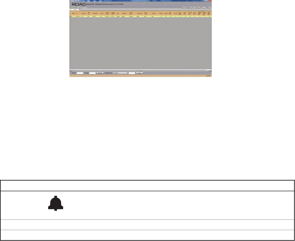
+ AC Input Only
+ DC Input Only
+ AC with Battery Revert
In addition to providing power to the noted FRU and controllers, the PS also provides the following:
• AC Failure detect signaling to the Modem
• Output over-current protection
• Integrated 2 stage 3 amp battery charger
Further details can be found in the individual sections of the respective FRU chapters of this manual.
1.7
Basic Repeater Level Troubleshooting – RDAC and LEDs
Diagnostic tests are available for the Modem, PA, and Power Supply Modules. If a problem occurs
during station operation, it is logged as an alarm that is read with the Repeater Diagnostic and Control
application (RDAC).
Figure 5: RDAC Diagnostic Screen
The station operator will then evaluate the problem locally or remotely, as the station maintains an
Alarm Log with the name of the alarm that has failed since the last power up. Via the RDAC
application's Alarm Log, the alarm messages will aid in identifying the FRU that failed along with the
fault condition.
After booting up the repeater, the seven LEDs (Power/Status, Tx Slot 1, Tx Slot 2, Rx Slot 1, Rx Slot 2,
Network, and Reference LEDs) will flash in unison.
The general status and condition of the SLR 5000 series repeater can be obtained by observing the
seven LED indicators on the front panel. Table 8: Front Panel LED indicators on page 45 shows the
LED symbols and their meaning, while Table 9: SLR 5000 Series Front Panel LED Definitions on page
46 identifies the information conveyed via the LED indicators.
Table 8: Front Panel LED indicators
LED Definition
Status
Tx A Tx Slot 1
Rx A Rx Slot 1
Table continued…
MN001436A01-AD
Chapter 1: SLR 5000 Series Repeater
Send Feedback 45
LED Definition
Tx B Tx Slot 2
Rx B Rx Slot 2
Ethernet Link/Network Connectivity
Reference
Table 9: SLR 5000 Series Front Panel LED Definitions
LED Function Name LED Color LED State Status Indication
Power/Status Off Off Off
Green Flashing Operating Normally, with DC power
Solid Operating Normally, with AC power
Red Flashing Repeater is Disabled (by customer)
Solid Not Operational – Major Alarm
Amber Flashing2Check Alarm Log – Alarm occurred and cleared but
remains latched (configurable)
Solid Repeater Operational – Minor Alarm
Tx A Off Off Transmitter is not transmitting
Green Solid Tx slot A or Analog (at desired power)
Amber 2Solid Tx slot A or Analog (at less than desired power)
Red 2Solid Tx Fail
Flashing Tx Inhibit
Rx A Off Off No receive carrier detected
Green Solid Rx Slot A or Analog (qualifier met)
Amber 2Solid Rx Slot A or Analog (non-qualified)
Tx B Off Off Transmitter is not transmitting
Green Solid Tx slot B or Analog (at desired power)
Amber 2Solid Tx slot B or Analog (at less than desired power)
Red 2Solid Tx Fail
Flashing Tx Inhibit
Rx B Off Off No receive carrier detected
Green Solid Rx Slot B or Analog (qualifier met)
Amber 2Solid Rx Slot B or Analog (non-qualified)
Table continued…
2Not supported in initial release.
MN001436A01-AD
Chapter 1: SLR 5000 Series Repeater
46 Send Feedback
LED Function Name LED Color LED State Status Indication
Ethernet/Network Con-
nectivity
Off Off No Ethernet connection
Green Solid Connectivity/Linked
Flashing Attempting to connect to the system
Reference Off Off No External Reference is present
Green Solid Locked to External Reference (1 pps 2, 5 MHz, 10
MHz)
NOTICE:
All LEDs flashing in unison indicate the repeater is booting up.
The RDAC application will be needed when the Status LED is red (solid or flashing). This status
indicates a minor or major alarm. The RDAC application is used to identify the specific alarm
and probable diagnosis to aid in identifying the FRU at fault.
1.8
Repeater Model Numbering Scheme
Model No.Example : AA R 1 0 Q C G A N Q 1 A N
Position : 1 2 3 4 5 6 7 8 9 10 11 12
Unique Variation
N: Standard Package
Version Letter
Package
1: Rack Mount
2: Cabinet
Preselector
Q: Standard Model (none)
Add-on Boards
N: None
P: Expansion Board
Performance
A: Standard
Power Level
B: 1–25 Watt
C: 1–50 Watt
Band
J: 136–174 MHz
K: 300–360 MHz
P: 350–400 MHz
Q: 400–470 MHz
T: 450–527 MHz
U: 806–941 MHz
Front Panel
G: LED Indicators
R: Repeater
AZ: Asia
LA: Latin America
AA: North America
MD: Europe
MOTOTRBO Repeater Model Series:
10: SLR 5000
Figure 6: Repeater Model Numbering Scheme
1.9
Model Chart
1.9.1
VHF High Power
SLR 5700, VHF, 136–174 MHz
Model/Item Description
AAR10JCGANQ1AN 136–174 MHz, 1–50 W SLR 5700 Repeater
X PMTD4013_S Modem Structure Kit/FRU
X PMTD4012_S Power Amplifier Structure Kit/FRU
X PMPN4026_S Power Supply Structure Kit/FRU
Table continued…
MN001436A01-AD
Chapter 1: SLR 5000 Series Repeater
Send Feedback 47

SLR 5700, VHF, 136–174 MHz
Model/Item Description
X PMLN6490_S Front Panel Board Structure Kit/FRU
X 3087791G01 Power Cable, US
X MN001443A01 Quick Start Guide
x = Indicates compatibility with model(s)
1.9.2
UHF R1 High Power
SLR 5700, UHF R1, 400–470 MHz
Model/Item Description
AAR10QCGANQ1AN 400–470 MHz, 1–50 W SLR 5700 Repeater
X PMTE4022_S Modem Structure Kit/FRU
X PMTE4023_S Power Amplifier Structure Kit/FRU
X PMPN4026_S Power Supply Structure Kit/FRU
X PMLN6490_S Front Panel Board Structure Kit/FRU
X 3087791G01 Power Cable, US
X MN001443A01 Quick Start Guide
x = Indicates compatibility with model(s)
1.9.3
UHF R2 High Power
SLR 5700, UHF R2, 450–527 MHz
Model/Item Description
AAR10TCGANQ1AN 450–527 MHz, 1–50 W SLR 5700 Repeater
X PMTE4510_S Modem Structure Kit/FRU
X PMTE4500_S Power Amplifier Structure Kit/FRU
X PMPN4026_S Power Supply Structure Kit/FRU
X PMLN6490_S Front Panel Board Structure Kit/FRU
X 3087791G01 Power Cable, US
X MN001443A01 Quick Start Guide
x = Indicates compatibility with model(s)
MN001436A01-AD
Chapter 1: SLR 5000 Series Repeater
48 Send Feedback

Chapter 2
SLR 5000 Series Satellite Receiver
2.1
Description
The main purpose of the Satellite Receiver is to eliminate "dead zones" in a communications system
by improving the "talk-in" coverage on a particular receive frequency when used in a receiver voting
system.
The Motorola Solutions SLR 5000 Series Repeater is not offered as an exclusive Satellite Receiver
only model, rather the repeater can be configured through the CPS to operate as a Satellite Receiver
in a receive only mode of operation. As such, the context of this chapter assumes that the repeater is
configured as a Satellite Receiver.
NOTICE: Configuring the repeater as a Satellite Receiver is only compatible with the
MOTOTRBO Digital Voting feature.
2.2
Operating Features
The features are identical to the SLR 5000 series repeater, with the exception that all transmitter
related functions are not applicable. See Operating Features on page 39 for more details.
2.3
Frequency Ranges
The supported frequency ranges are identical to the SLR 5000 series repeater's receive frequency
ranges. See Frequency Ranges and Power Levels on page 41 for more details.
2.4
Specifications
The specifications are identical to the SLR 5000 series repeater, with the exception that all transmitter
related specifications are not applicable. See Specifications on page 41 for more details.
2.5
Configuration
Other than setting the general personality configurations, one must additionally set the “Operation
Mode” parameter under the “General Settings” menu in the CPS to that of “Digital Satellite
Receiver.”See Figure 7: “Operation Mode” configuration for Satellite Receiver Functionality on page
50 for the screenshot of the “Operation Mode” parameter.
MN001436A01-AD
SLR 5000 Series Satellite Receiver
Send Feedback 49
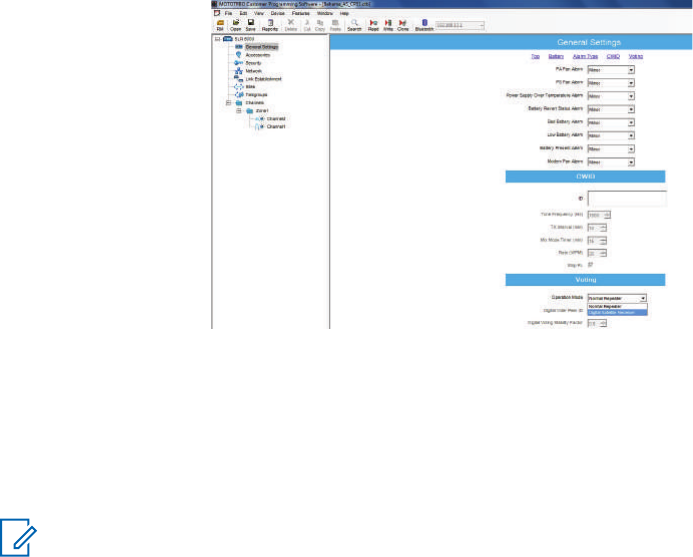
Figure 7: “Operation Mode” configuration for Satellite Receiver Functionality
2.6
Basic Station Level Troubleshooting – RDAC and LEDs
The troubleshooting procedures are similar to the SLR 5000 series repeater with regards to the control,
power supply, and receiver sub-systems. See Basic Repeater Level Troubleshooting – RDAC and
LEDs on page 45 for more details.
NOTICE: When configured for receiver only operation, the SLR 5000 series repeater does not
support any transmitter sub-system functions. As such, disregard all references to the
transmitter section in Basic Repeater Level Troubleshooting – RDAC and LEDs on page 45.
This includes any transmitter related topics in the RDAC and the front panel LEDs.
2.7
Model Chart
The model chart is identical to the SLR 5000 series repeater. See Model Chart on page 47 for more
details.
MN001436A01-AD
Chapter 2: SLR 5000 Series Satellite Receiver
50 Send Feedback

Chapter 3
SLR 5000 Series Modem
3.1
Description
The Modem Module is described in this section. A general description, identification of inputs and
outputs, and functional theory of operation are provided. The information provided is sufficient to give
service personnel a functional understanding of the module, allowing maintenance and troubleshooting
to the module level.
3.1.1
General Description
The Modem Module consists of a single printed circuit board in a clamshell housing assembly. It
provides the receiver, exciter and station control functionality for the repeater. Additionally the external
connections to the station are connected directly to the modem module.
NOTICE: The modem cooling fan is replaceable and external to the modem itself. See SLR
5000 Series Maintenance and Disassembly/Reassembly on page 97 for replacement details.
3.1.2
Input and Output Connections
The following figure shows the Modem Module input and output external connections.
MN001436A01-AD
SLR 5000 Series Modem
Send Feedback 51
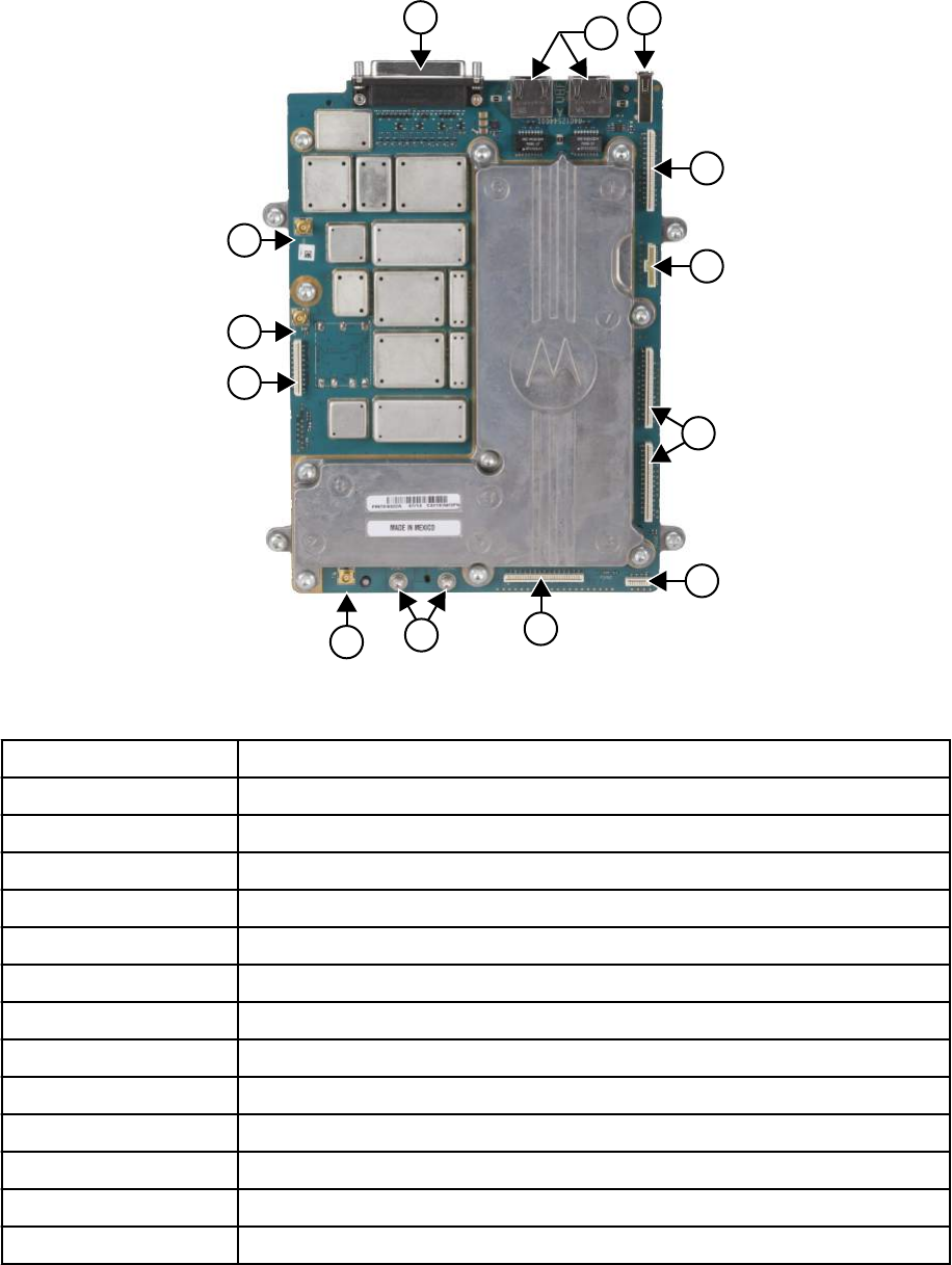
Figure 8: Modem Module Connector Locations
13
12
11
10
23
4
5
6
7
8
9
(+) (-)
1
Table 10: Callout Legend
Label Description
1 Auxiliary Connector
2 Ethernet Connectors
3 USB Host
4 Future Expansion Port
5 PSU Digital Interface
6 Future Expansion Ports
7 Chassis ID Connector
8 Front Panel Interface
9 DC Power Input
10 Tx Exciter Output
11 PA Digital Interface
12 External Reference Input
13 Receiver Input
MN001436A01-AD
Chapter 3: SLR 5000 Series Modem
52 Send Feedback

3.1.3
Frequency Bands
The Modem Module covers the following bands with unique models:
• VHF
• UHF R1
• UHF R2
3.2
Receiver Subsystem
The Modem Module includes the receiver circuitry for the station. A cable connects the board
connector to a BNC connector located on the rear panel of the repeater. See Figure 8: Modem Module
Connector Locations on page 52 for the location of this connector. The receiver section performs
highly-selective bandpass filtering and dual down-conversion of the desired RF signal. A custom
Receiver IC then performs an analog-to-digital conversion of the desired received signal and outputs
the digitized signal to the controller section via a serial synchronous interface. Included in the receiver
section is:
• Frequency Synthesizer Circuitry – Consists of a phase-locked loop and Voltage-Controlled
Oscillator (VCO), generates the first LO injection signal.
• Varactor-tuned Preselector Filter(s) – Provides bandpass filtering of the station Receiver RF input.
• Receiver Front End Circuitry – Performs filtering, amplification, and the first down conversion of the
Receiver RF signal.
• Receiver-specific piece of transceiver IC Circuitry – Consists of receiver-specific parts of a
transceiver IC which performs the second down conversion, filtering, amplification, and analog-to-
digital conversion of the receive signal.
• Analog to Digital Converter (ADC) Circuitry – Converts analog Receiver status signals to digital
format for transfer to the controller circuitry located on the Modem Module.
3.2.1
Specifications
Table 11: Specifications of Receiver Subsystem
Parameter Specifications
VHF UHF
Frequency Bands 136–174 MHz UHF R1, 400–470 MHz
UHF R2,450–527 MHz
Selectivity 25 kHz/12.5 kHz (TIA603D) 83 dB/55 dB 80 dB/55 dB
Selectivity 25 kHz/12.5 kHz (TIA603) 83 dB/68 dB 80 dB/68 dB
Selectivity 25 kHz/12.5 kHz (ETSI) 70 dB/63 dB
Sensitivity (12 dB SINAD) 0.22 uV
Sensitivity (5% BER) 0.22 uV
Intermodulation Rejection (TIA603D) 82 dB
Intermodulation Rejection (ETSI) 73 dB
Table continued…
MN001436A01-AD
Chapter 3: SLR 5000 Series Modem
Send Feedback 53
Parameter Specifications
VHF UHF
Spurious Rejection (TIA603D) 95 dB
Spurious Rejection (ETSI) 90 dB
Audio Distortion <1%
FM Hum and Noise 25 kHz/12.5 kHz -50 dB/-45 dB
3.3
Transmitter Exciter Subsystem
The Exciter Subsystem in the Modem Module (in conjunction with the Power Amplifier Module)
provides the transmitter functions for the station. The Exciter circuitry generates a low-level modulated
Radio Frequency (RF) signal which is input to the Power Amplifier (PA) module for further amplification
and output to the transmit antenna. A coaxial cable is used to connect the Tx exciter output to the PA
module. See Figure 8: Modem Module Connector Locations on page 52 for the exact location of this
connector. The Exciter Module interfaces directly with the controller section, which provides control
signals and monitoring, and routes transmit data to the Exciter.
The RF carrier is generated by a frequency synthesizer consisting of synthesizer circuitry and Voltage-
Controlled Oscillator (VCO) circuitry. Exciter circuit control signals, monitoring, and audio processing
are handled by the controller section of the Modem Module. The power leveling circuitry of the
transmitter system is located in the Power Amplifier Module and passed onto the exciter stages
through the PA-Modem interface flex cable. See Figure 8: Modem Module Connector Locations on
page 52 for the location. Included in the exciter section are:
• Frequency Synthesizer Circuitry – Consists of a phase-locked loop and Voltage-Controlled
Oscillator (VCO), generates a modulated RF signal at the transmitter carrier frequency.
• RF Isolation Switch – Allows the controller section to turn on/off the Exciter RF input signal which
greatly reduces the signal supplied to the Power Amplifier module.
• Analog to Digital Converter (ADC) Circuitry – Converts the analog Exciter status signals to the
digital format for transfer, upon request, to the controller section of the Modem Module.
• Low Level Amplifiers – Amplify and buffer the modulated RF signal from the VCO for delivery to the
Power Amplifier Module.
3.3.1
Specifications
Table 12: Specifications of Transmitter Exciter Subsystem
Parameter Specifications
VHF UHF
Frequency Range 136–174 MHz UHF R1, 400–470 MHz
UHF R2, 450–527 MHz
Electronic Bandwidth Full Bandwidth
Output Power 6 W 6.2 W
Harmonics -20 dBc
MN001436A01-AD
Chapter 3: SLR 5000 Series Modem
54 Send Feedback
3.4
Station Control Subsystem
The Station Control Subsystem is described in this section. A general description, identification of
controls, indicators, and inputs/outputs, a functional block diagram, and functional theory of operation
are provided.
The Controller circuitry performs the digital signal processing, data formatting and audio routing for the
station and provides the external interfaces to the rest of the site.
The Controller section consists of 7 main ICs. These are:
• Texas Instrument DM8148 Host/DSP Processor
• EMMC Flash memory
• DDR3 memory
• Texas Instruments Power Management IC
• NOR Flash
• 2-TI AIC3204 Codecs
General controller functionality includes:
• Data and Control interface to the transceiver ICs
• Audio interface with CODEC ICs
• UART interface to expansion board
• Intermodule communication (SPI, I2C)
• Two Ethernet ports
• USB Device port
• USB Host port
• External physical interfaces (connectors, LEDs, external references etc.)
• Station Reference Control
3.4.1
High Stability Reference Block
The high-stability reference block can be used to enhance the 0.5 ppm Voltage Controlled
Temperature Compensated Crystal Oscillator. The block diagram shown in Figure 9: High Stability
Reference Circuit on page 55. An external reference can be applied to lock the on board VCTCXO.
This function can be enabled via the customer programming software. The connection is made through
a cable connecting a BNC connector on the rear panel to a connector on the modem module. The
location of the connector on the modem module can be found in Figure 8: Modem Module Connector
Locations on page 52.
Figure 9: High Stability Reference Circuit
19.2MHz
VCTCXO
DAC Output
from
Transceiver IC
PLL
Ref_Lck_Det
Lock
Detect
Tune
STD_EN
VCTCXO
LOOP
FILTER Phase
Detector
Loop Divider
SPI
External
Reference
3.4.2
Audio
The analog audio stages are used exclusively for external accessories connected through the rear
DB25 accessory connector.
MN001436A01-AD
Chapter 3: SLR 5000 Series Modem
Send Feedback 55
The critical components of the audio circuit are the TI DM8148 processor and a pair of Texas
Instruments AIC3204 dual channel audio codecs. Figure 10: Audio Block Diagram on page 56 details
the specific interconnects between the critical components.
Figure 10: Audio Block Diagram
TI DM8148
(DSP Core)
TI AIC3204
Audio
Codec 1
TI AIC3204
Audio
Codec 2
Rear Accessory Connector
(DB25)
I²C2 (2)
I²C0 (2)
Audio SSI (4)
TX Audio 1 (Pin 1 & 22)
RX Audio 1 (Pin 7)
TX Data (Pin 13)
RFIC SSI (4)
RX Audio 2
TX Audio 1
TX Data
TX Audio 2
RX Audio 1
The repeater digital audio is handled primarily by the DM8148 processor. The TX RFIC generates a
24.576 MHz master clock (MCLK) that the DM8148 uses to drive its McASP SSI interface for the audio
codecs. The bulk of the audio processing is done in the DaVinci’s DSP core. The audio codecs contain
DACs and ADCs and handle the conversion of the digital audio to analog audio and vice versa.
There are 2 TX audio lines routed in from the rear accessory connector. These are TX Audio 1 (Pins 1
and 22, used for analog and slot 1 digital), and TX Data (Pin 13).
For the RX outputs, there is only 1 which is connected to the accessory connector. RX Audio 1 on
pin 7 (to be used for analog and slot 1 digital).
3.5
Station Control Interface
3.5.1
Front Panel Interface Connector
Refer Modem Interface on page 70 for details.
3.5.2
Rear Panel Connections
Refer USB on page 73 to Auxiliary (Aux) on page 75 for details.
3.5.3
Power Amplifier Interface Connector
The digital interface to the power amplifier module utilizes a 20 pin vertical LIF connector. See
Figure 8: Modem Module Connector Locations on page 52 for the locations of these connectors. Figure
11: Power Amplifier Interface Connector Pin Locations on page 56 shows the pin number locations.
Figure 11: Power Amplifier Interface Connector Pin Locations
Pin 1 Pin 20
MN001436A01-AD
Chapter 3: SLR 5000 Series Modem
56 Send Feedback
3.5.4
Power Supply Interface Connector
The power supply digital interface utilizes a 15 pin Pico-ClaspTM connector. The location is detailed in
Figure 8: Modem Module Connector Locations on page 52. Figure 12: Power Supply Interface
Connector Pin Locations on page 57 shows the pin number locations.
Figure 12: Power Supply Interface Connector Pin Locations
Pin 15 Pin 1
3.5.5
Expansion Board Interface Connector
The expansion board interface utilizes a 30 pin vertical LIF connector. The location is detailed in
Figure 8: Modem Module Connector Locations on page 52. Figure 13: Expansion Board Interface
Connector Pin Locations on page 57 shows the pin number locations.
Figure 13: Expansion Board Interface Connector Pin Locations
Pin 1 Pin 30
3.5.6
Chassis ID Interface Connector
The Chassis ID utilizes an 8 pin vertical LIF connector. The location is detailed in Figure 8: Modem
Module Connector Locations on page 52.
Figure 14: Chassis ID Interface Connector Pin Locations on page 58 shows the pin number
locations. The repeater chassis information is necessary for warranty and purchased software features
so this must be connected.
MN001436A01-AD
Chapter 3: SLR 5000 Series Modem
Send Feedback 57
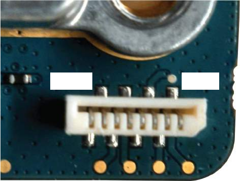

Chapter 4
SLR 5000 Series Power Amplifier
4.1
Description
The Power Amplifier Module is described in this section. A general description, identification of inputs
and outputs and functional theory of operation are provided. The information provided is sufficient to
give service personnel a functional understanding of the module, allowing maintenance and
troubleshooting to the module level.
4.1.1
General Description
The Power Amplifier (PA) is a forced convection-cooled RF power amplifier. It accepts a low-level
modulated RF signal from the Exciter Module, and amplifies it for transmission via the site transmit
antenna port. The PA is non-linear, and is therefore used for Continuous Wave (CW) applications only.
The output power is continually monitored and regulated by a feedback and control loop, with a power
output control voltage being generated by the transmitter control circuitry located on the PA. All
configuration and control signals are connected to the modem module via the flex connected between
the modules.
NOTICE: The power amplifier cooling fan is replaceable and external to the power amplifier
itself. See SLR 5000 Series Maintenance and Disassembly/Reassembly on page 97 for
replacement details.
4.2
Input and Output Connections
The following figure shows the PA input and output connections.
MN001436A01-AD
SLR 5000 Series Power Amplifier
Send Feedback 59
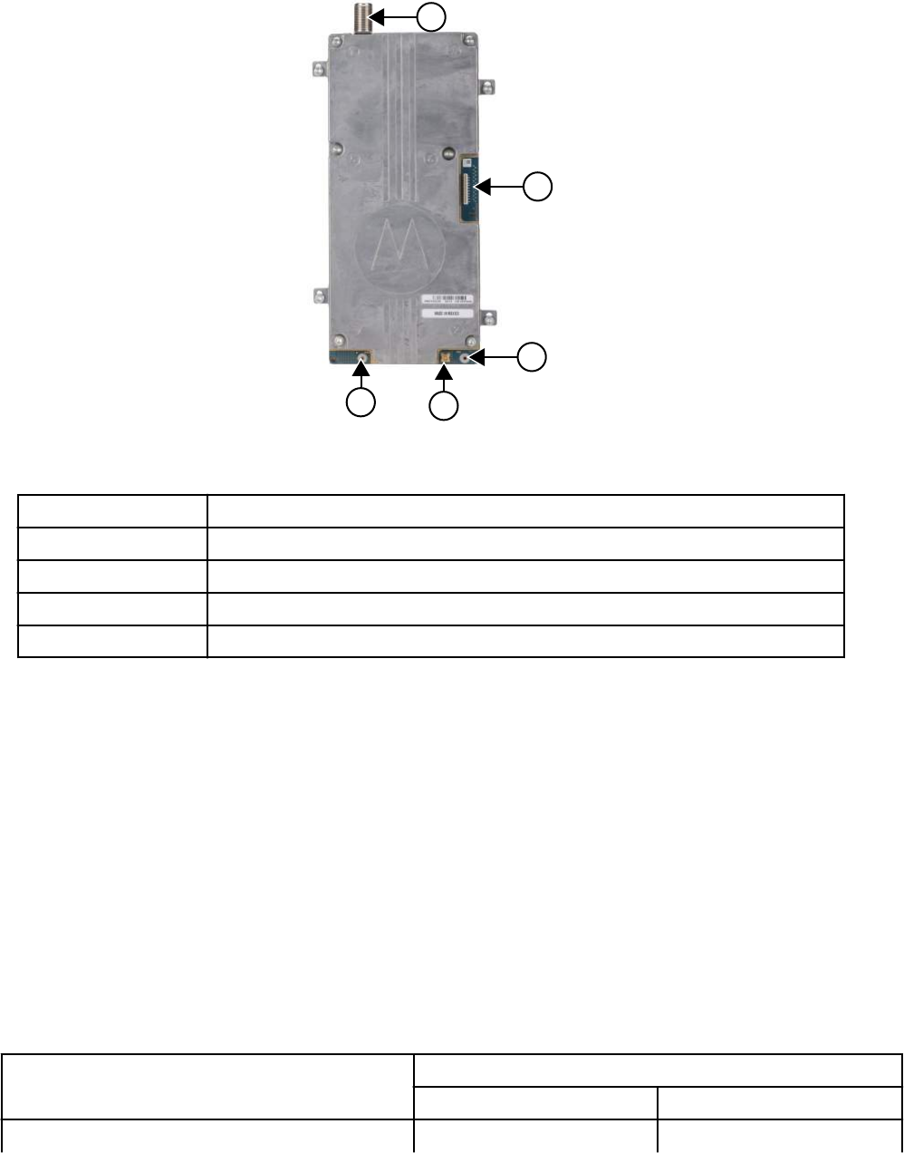
Figure 15: Input and Output Connections
(+)(-)
1
2
4
3
3
Table 13: Callout Legend
Label Description
1 Antenna Port
2 Modem Interface
3 DC Input
4 Exciter Input
4.3
Frequency Ranges
The power amplifier modules models cover the following ranges:
• 136–174 MHz
• UHF R1, 400–470 MHz
• UHF R2, 450–527 MHz
4.4
Specifications
Specifications of the SLR 5000 series repeater's Power Amplifier (PA) are available in the following
table.
Table 14: Specifications of Power Amplifier
Parameter Specifications
VHF UHF
Operational Frequency Range 136–174 MHz UHF R1, 400–470 MHz
Table continued…
MN001436A01-AD
Chapter 4: SLR 5000 Series Power Amplifier
60 Send Feedback
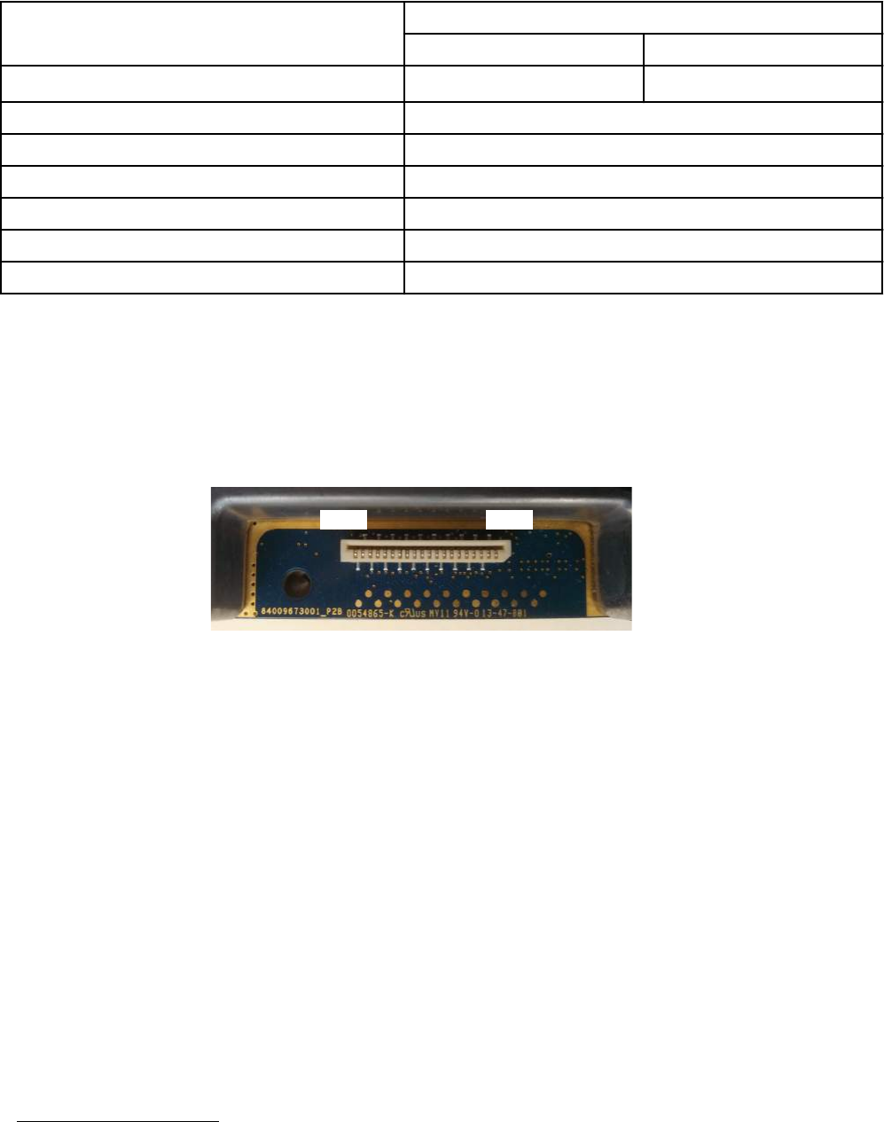
Parameter Specifications
VHF UHF
UHF R2, 450–527 MHz
Minimum Input Return Loss (Tx mode) 15 dB
Rated RF Input Power 37 dBm
Maximum Standby Power Consumption 0.5 W
Rated RF Output Power Range 1–50 W
Supply Nominal Voltage 313.6 V (+/- 10%)
Maximum Current Draw 412.0 A
4.5
Modem Interface
The digital interface to the modem module utilizes a 20 pin vertical LIF connector. It’s location is shown
in Figure 15: Input and Output Connections on page 60. See Figure 16: Modem Interface Connector
Pin Locations on page 61 for front panel interface connector pin locations.
Figure 16: Modem Interface Connector Pin Locations
Pin 20 Pin 1
3When the SLR 5000 series repeater is operating from a DC source, the PA input voltage follows
the repeater's DC input source.
4Nominal VSWR conditions (VSWR <1.5:1)
MN001436A01-AD
Chapter 4: SLR 5000 Series Power Amplifier
Send Feedback 61
This page intentionally left blank.

Chapter 5
SLR 5000 Series Power Supply
5.1
Description
In this chapter, a general description, performance specifications, and identification of the inputs and
outputs are given for the power supply. The information provided is sufficient to give service personnel
a functional understanding of the module, allowing maintenance and troubleshooting to the module
level. (See SLR 5000 Series Maintenance and Disassembly/Reassembly on page 97 for detailed
removal or installation procedures for all modules in the SLR 5000 series repeater.)
5.1.1
General Description
The power supply, with front-to-rear airflow, operates from either an AC or DC input and provides the
DC operating voltage for the SLR 5000 series repeater. The power supply also provides an integrated
battery charger to maintain the charge on a negatively grounded 12 VDC (nominal) battery system.
Figure 17: Front View of the SLR 5000 Series Power Supply on page 64 displays the front and rear
views of the SLR 5000 series Power Supply.
Additionally, the power supply affords the following performance features:
• Power Factor Correction (PFC) – aids in lowering the ampacity requirements of the AC power
source.
• Over-Voltage Protection (OVP) – lowers the risk of damaging the repeater should input AC or DC
levels approach damaging levels.
• Over-Current Protection (OCP) – aids in preventing a cascaded failure within the repeater.
• Reverse Polarity Protection – aids in preventing damage to the repeater due to installation mishaps.
• Configurable Battery Charger Voltage – tailors the float voltage to your battery manufactures
charging recommendations.
• Configurable Low Voltage Disconnect (LVD) – tailors the battery disconnect voltage to your battery
manufactures recommendations.
• Configurable Power Source Preference – when both AC and DC sources are present (and within
their respective operational bounds), this feature allows one to select the primary power source the
repeater uses.
• Battery Revert – should the AC source be interrupted, this function allows the power supply to
seamlessly transfer to a DC source until the AC source is restored. This results in uninterrupted
radio service for as long as DC power can be provided.
NOTICE: A user supplied external 12 V (nominal) battery system is required to support the
battery backup feature so that when the AC power fails, the SLR 5000 series repeater can
be powered from a DC battery source if it is connected to the PS.
NOTICE: The power supply cooling fan is replaceable and external to the power supply
itself. See SLR 5000 Series Maintenance and Disassembly/Reassembly on page 97 for
replacement details.
MN001436A01-AD
SLR 5000 Series Power Supply
Send Feedback 63
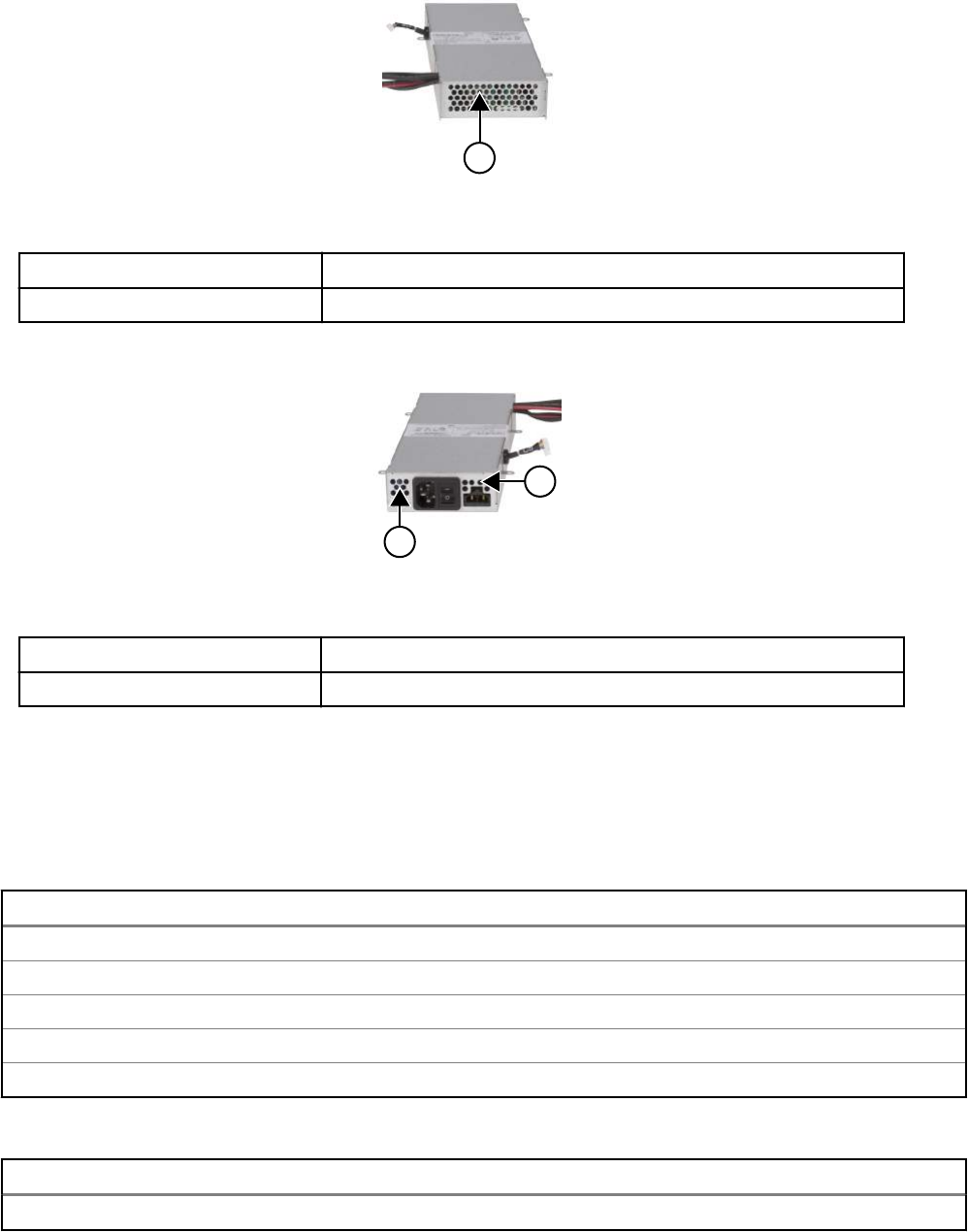
Figure 17: Front View of the SLR 5000 Series Power Supply
1
Table 15: Callout Legend
Label Description
1 Air Intake
Figure 18: Rear View of the SLR 5000 Series Power Supply
1
1
Table 16: Callout Legend
Label Description
1 Air Exhaust
5.2
Specifications
The following tables show the electrical performance specifications for the Power Supply.
Table 17: Power Supply AC Performance Specifications
Parameter Value or Range
Input Voltage Range 100–240 VAC
Input Frequency Range 47–63 Hz
Steady State Output Voltage 13.6 ± 0.25 VDC
Output Current (Max) 23 A (excluding charger current)
Output Ripple: 30 mVp-p @ 25 °C (77 °F)
Table 18: Power Supply DC Performance Specifications
Parameter Value or Range
Input Voltage Range 11–15.5 VDC
Table continued…
MN001436A01-AD
Chapter 5: SLR 5000 Series Power Supply
64 Send Feedback
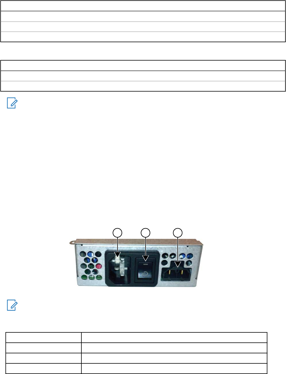
Parameter Value or Range
Steady State Output Voltage Input voltage dependent (0–0.4 V below input)
Output Current (Max) 26 A
Output Ripple: 30 mV p-p, @ 25 °C (77 °F)
Table 19: Power Supply Battery Charger Performance Specifications
Parameter Value or Range
Charging Voltage Range 13.5–14.2 VDC (default 13.8 VDC: configurable)
Charging Current (Max) 3 A (in addition to output current)
NOTICE:
California Energy Commission (CEC) Compliance testing was performed with the following
recommended 12 V Lead-acid battery:
• Sprinter S12V370NGF
• GNB Industrial Power, a division of Exide Technologies, Aurora, Illinois, USA 60504
Charge time may take up to 40 hr.
5.3
Power Supply Interface
This section describes the power supply interface such as the power source inputs, power supply
outputs, its digital interface, and the power supply output cable signaling.
5.3.1
Power Source Inputs
Figure 19: Power Source Inputs
1 2 3
NOTICE: When the power switch is in standby, all outputs are disabled (regardless of input
source(s) connected). This includes the charger output as well (if charging is enabled).
Table 20: Callout Legend
Label Description
1 AC Source Input Connector
2 Power Switch
3 DC Source Input Connector (also charging output)
MN001436A01-AD
Chapter 5: SLR 5000 Series Power Supply
Send Feedback 65
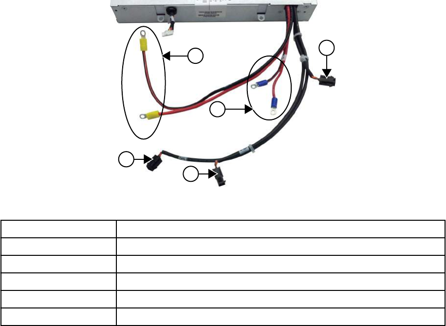
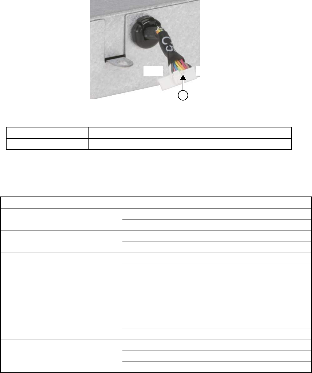
5.3.3
Power Supply Digital Interface
Figure 21: Power Supply Digital Interface
1
Pin 15 Pin 1
Table 22: Callout Legend
Label Description
1 Modem Interface
5.3.4
Power Supply Output Cable Signaling
Table 23: Power Supply Output Cable SIgnalling
Output Load Signal
Power Amplifier Red – 13.6 VDC (nominal)
Black with Red Strip – Ground
Modem Red – 13.6 VDC (nominal)
Black with Red Strip - Ground
Power Amplifier Fan Red – 13.6 VDC (nominal)
Black – Ground
Yellow – Fan speed detect
Brown – Fan speed control
Modem Fan Red – 13.6 VDC (nominal)
Black – Ground
Yellow – Fan speed detect
Brown – Fan speed control
Power Supply Fan Red – 13.6 VDC (nominal)
Black – Ground
Yellow – Fan speed detect
Table continued…
MN001436A01-AD
Chapter 5: SLR 5000 Series Power Supply
Send Feedback 67

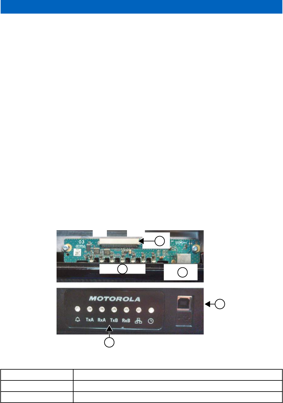
Chapter 6
SLR 5000 Series Front Panel
6.1
Description
The Front Panel Module is described in this section. A general description, identification of inputs and
outputs and functional theory of operation are provided. The information provided is sufficient to give
service personnel a functional understanding of the module, allowing maintenance and troubleshooting
to the module level.
6.1.1
General Description
The Front Panel board user interface includes seven LED indicators and a USB device port.
The board is connected to the modem via a 30 pin flex cable. The LED indicators inform the user of the
state of the repeater while the USB device port is used to interface with the repeater through the
Customer Programming Software (CPS). The LED indications are transferred to the front panel via a
serial peripheral interface.
6.2
Input and Output Connections
Figure 22: Front Panel Input and Output Connections on page 69 shows the various front panel Input
and Output connections.
Figure 22: Front Panel Input and Output Connections
1
3
2
4
5
Pin 1 Pin 30
Table 24: Callout Legend
Label Description
1 Modem Interface
2 LED Indicators
Table continued…
MN001436A01-AD
SLR 5000 Series Front Panel
Send Feedback 69

Label Description
3 USB Device Connector
4 USB Device Connector
5 LED Indicators
6.3
Interfaces
6.3.1
Modem Interface
The interface to the modem is made via a 30 pin flex cable. The connector on the front panel board is a
30 pin horizontal LIF connector. The location can be seen in Figure 22: Front Panel Input and Output
Connections on page 69.
6.3.2
User/Service Interface
6.3.2.1
USB
The Front Panel USB device port is the interface used for connecting the repeater to a computer in
order to use the Customer Programming Software. See Figure 22: Front Panel Input and Output
Connections on page 69 for the location. A standard “Type A” to “Type B” USB cable facilitates the
connection. See Appendix A: Accessories on page 133, Service Tools on page 135 for the noted USB
cable part number.
6.3.2.2
LED Indicators
The Front Panel houses seven LED indicators used for displaying the state of the repeater. For state
details, refer to Table 9: SLR 5000 Series Front Panel LED Definitions on page 46.
MN001436A01-AD
Chapter 6: SLR 5000 Series Front Panel
70 Send Feedback
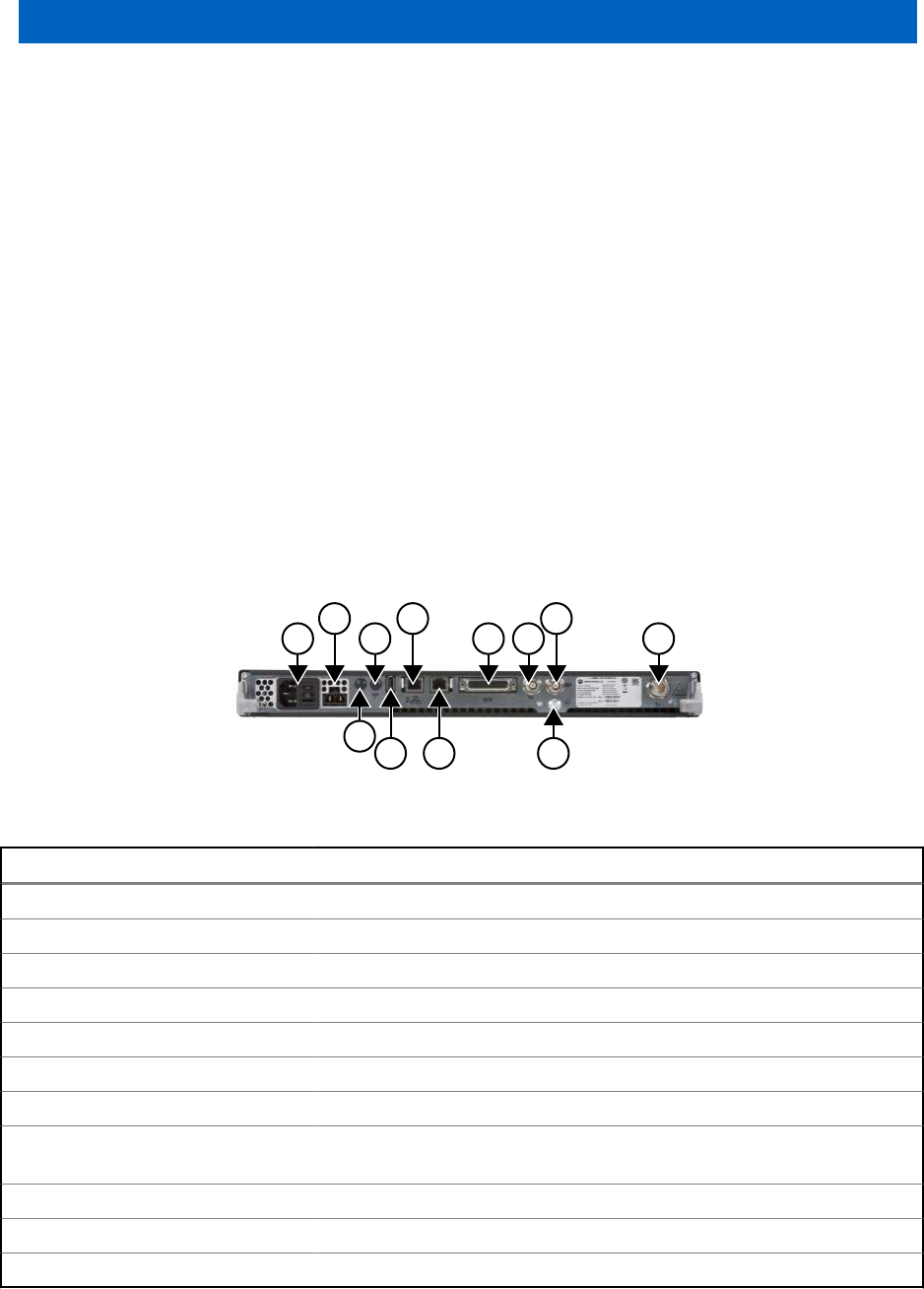
Chapter 7
SLR 5000 Series Back Panel
7.1
Description
The Back Panel interface provides the electrical interconnection interface between the SLR 5000
Series Repeater and the end user's system.
This includes the connectors necessary to interface the repeater to RF peripheral equipment, power
system, system controllers, LANs, as well as other communications and maintenance equipment. This
section provides a general description, identification of inputs/outputs, and a pin-out listing for all
connectors, including information on signal names, functions, and levels.
7.1.1
General Description
Figure 23: Back Panel Connector Names and Locations on page 71 shows the various interface
connector locations. Table 25: Connector Type and Primary Function on page 71 lists the connector
types as well as its primary function.
Figure 23: Back Panel Connector Names and Locations
1
2
3
4
5
6
8
711
9
10
12
Table 25: Connector Type and Primary Function
Location Connector Type Function(s)
1 C14 (IEC 60320) AC Power Inlet and Repeater Power Switch
2 Molex 42818-0212 DC Power Inlet and DC Charger Outlet
3 Option Dependent Option Dependent 1
4 Option Dependent Option Dependent 2
5 Type A Socket USB
6 RJ-45 – Jack Ethernet 2
7 RJ-45 – Jack Ethernet 1
8 DB25 – Female Aux: Rx Audio, Tx Audio, PTT, COR, Accessory Power, 1 PPS, and
GPIO
9 BNC – Female Receiver RF (Rx)
10 BNC – Female Frequency Reference Input (REF)
11 T30 TORX Screw Bonding Ground Connection
Table continued…
MN001436A01-AD
SLR 5000 Series Back Panel
Send Feedback 71
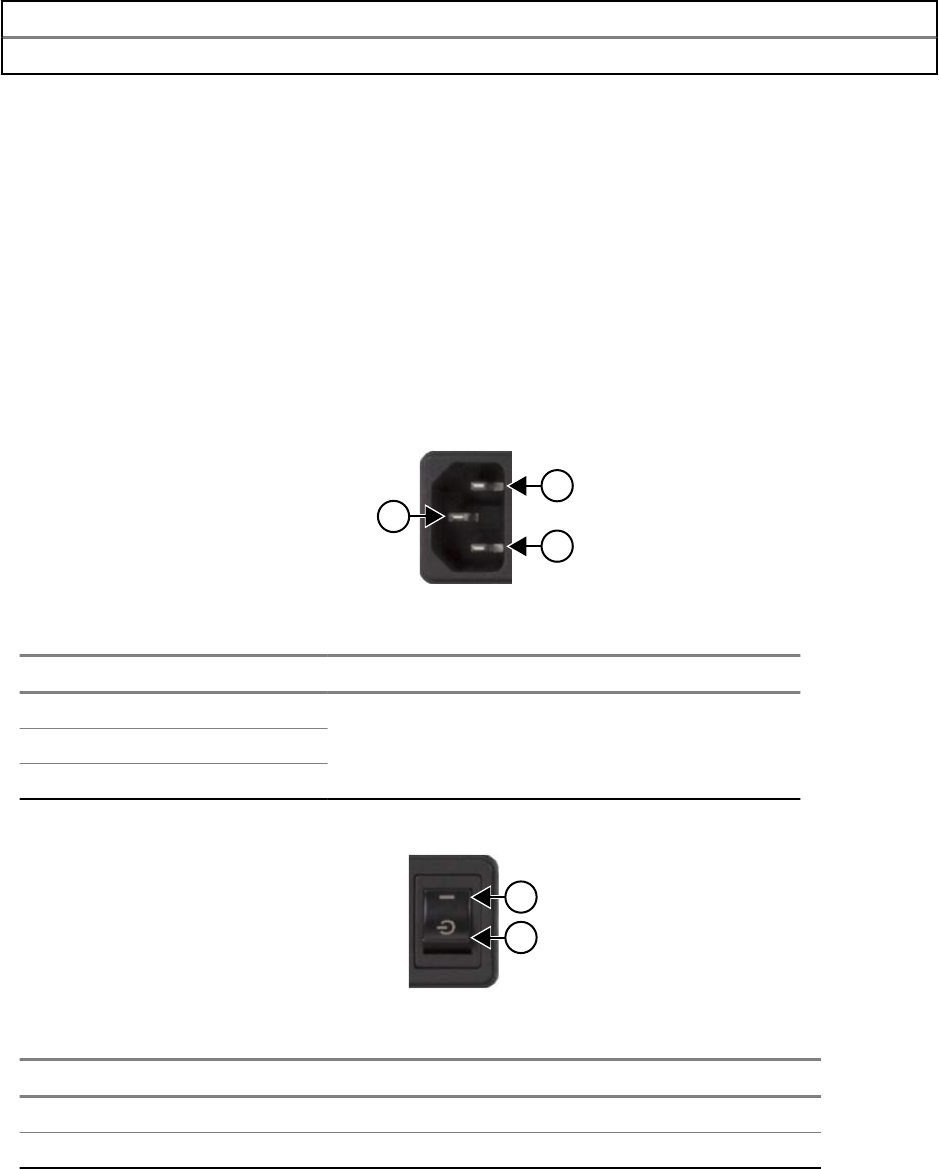
Location Connector Type Function(s)
12 N-Type – Female Transmitter RF (Tx)
7.2
Back panel Interfaces
This section describes the back panel interfaces of the SLR 5000 Series Repeater.
7.2.1
AC Power Inlet
The AC power inlet connector is of the C14 type socket (IEC 60320) and accepts interface to C13 type
plugged (IEC 60320) power cords. Figure 24: AC Power Inlet Connector on page 72 shows the
location of the pins and Table 26: AC Power Inlet Connector on page 72 lists the functional
characteristics of the connector's pins.
Figure 24: AC Power Inlet Connector
1
2
3
Table 26: AC Power Inlet Connector
Location Pin Assignment Type Signal Characteristics
1 Earth
Power
100–240VAC (Line to Neutral)
4 A (max)
2 Line
3 Neutral
Figure 25: Repeater Power Switch
1
2
Table 27: Callout Legend
Label Description
1 ON (fully powered)
2 STANDBY
7.2.2
DC Power Inlet/DC Charger Outlet
The DC power inlet/DC charger outlet connector is a Molex 42818-02012 panel mount receptacle and
accepts interface to Molex 42816-0212 plugs. Figure 26: DC Power Inlet/DC Charger Outlet Connector
MN001436A01-AD
Chapter 7: SLR 5000 Series Back Panel
72 Send Feedback
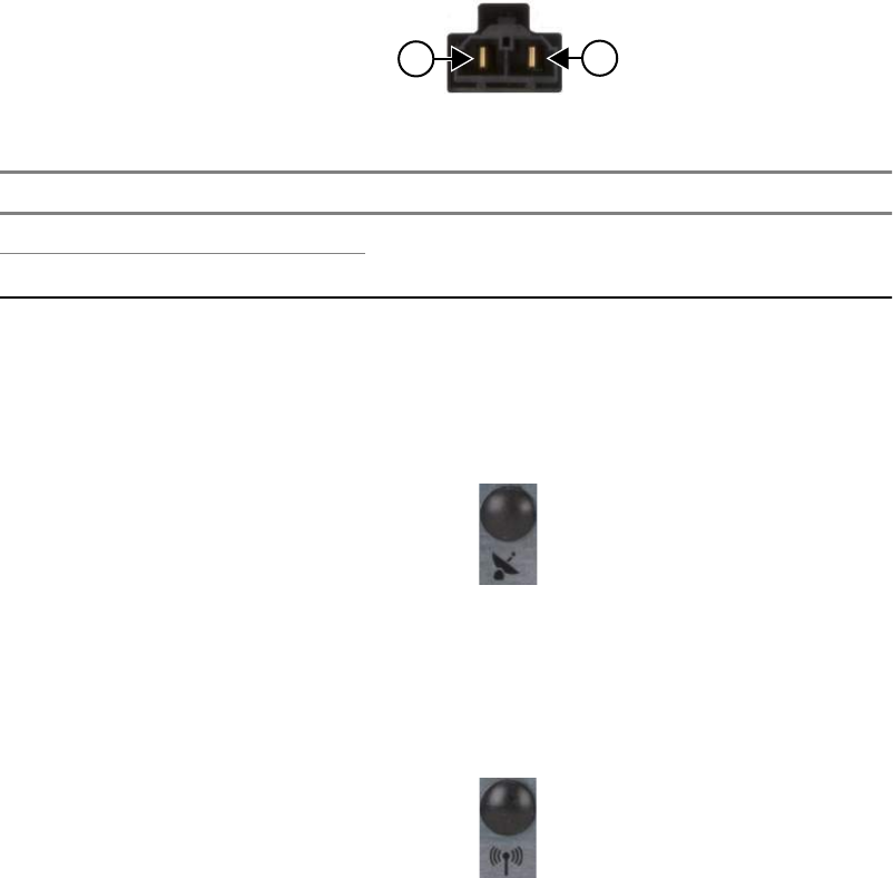
on page 73 shows the location of the pins and Table 28: DC Power Inlet/DC Charger Outlet
Connector on page 73 lists the functional characteristics of the connector's pins.
Figure 26: DC Power Inlet/DC Charger Outlet Connector
12
Table 28: DC Power Inlet/DC Charger Outlet Connector
Location Pin Assignment Type Signal Characteristics
1 Positive
Power
11–14.4VDC
17 A (max)
2 Negative
7.2.3
Option 1/GNSS
Not supported at this time (No connection)
Figure 27: Option 1/GNSS Connector
7.2.4
Option 2/WLAN
Not supported at this time (No connection)
Figure 28: Option 2/WLAN Connector
7.2.5
USB
Not supported at this time. Type A socket (Host Connection) that supports the USB 2.1 protocol
standard. See Figure 29: USB Connector on page 74 and Table 29: USB Connector on page 74
the location of the pins and the functional characteristics of the connector's pins.
MN001436A01-AD
Chapter 7: SLR 5000 Series Back Panel
Send Feedback 73
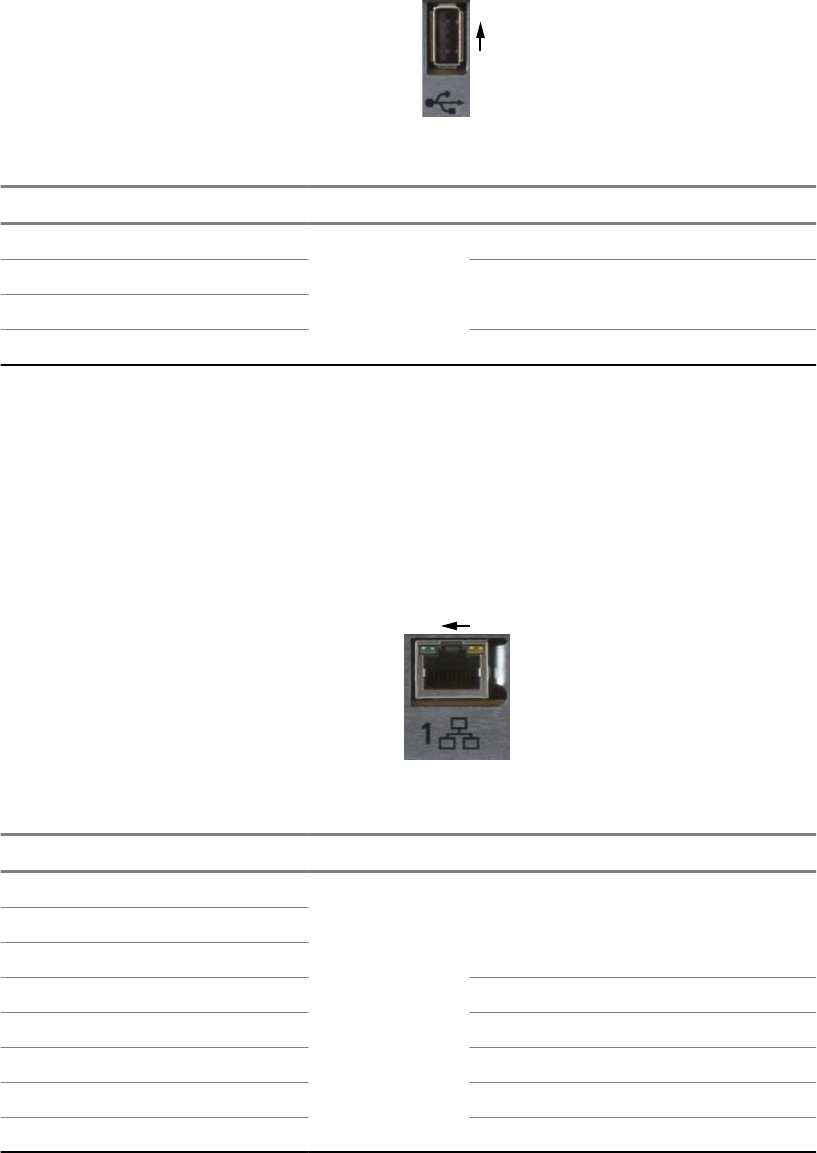
Figure 29: USB Connector
1
4
Table 29: USB Connector
Location Pin Assignment Type Signal Characteristics
1 VBUS
USB Physical
Layer
+5 VDC
2 D- 3.6 V differential data
3 D+
4 GND Ground
7.2.6
Ethernet 1
Fully compliant with IEEE and 802.3 and 802.3u standards. Supports 10Base-T, 100Base-Tx rates, full
duplex, half duplex mode and flow control. See the Figure 30: Ethernet 1 Connector on page 74 and
Table 30: Ethernet 1 Connector on page 74 for the location of the pins and the functional
characteristics of the connector's pins.
Figure 30: Ethernet 1 Connector
1
8
Table 30: Ethernet 1 Connector
Location Pin Assignment Type Signal Characteristics
1 Ethernet Tx+
Ethernet
Physical Layer
5 V differential data
2 Ethernet Tx-
3 Ethernet Rx+
4 Unused N/A
5 Unused N/A
6 Ethernet Rx- 5 V differential data
7 Unused N/A
8 Unused N/A
MN001436A01-AD
Chapter 7: SLR 5000 Series Back Panel
74 Send Feedback
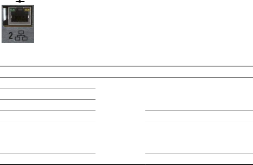
7.2.7
Ethernet 2
Not supported at this time. Fully compliant with IEEE and 802.3 and 802.3u standards. Supports
10Base-T, 100Base-Tx rates, full duplex, half duplex mode and flow control. See Figure 31: Ethernet 2
Connector on page 75 and Table 31: Ethernet 2 Connector on page 75 for the location of the pins
and the functional characteristics of the connector's pins.
Figure 31: Ethernet 2 Connector
1
8
Table 31: Ethernet 2 Connector
Location Pin Assignment Type Signal Characteristics
1 Ethernet Tx+
Ethernet
Physical Layer
5 V differential data2 Ethernet Tx-
3 Ethernet Rx+
4 Unused N/A
5 Unused N/A
6 Ethernet Rx- 5 V differential data
7 Unused N/A
8 Unused N/A
7.2.8
Auxiliary (Aux)
This connection supports the analog interface to the SLR 5000 series repeater, which includes audio,
station control, station indicators, accessory power, and provisions for timing used in various system
implementations. See the following figure and table for location of the pins and the functional
characteristics of the connector's pins.
MN001436A01-AD
Chapter 7: SLR 5000 Series Back Panel
Send Feedback 75
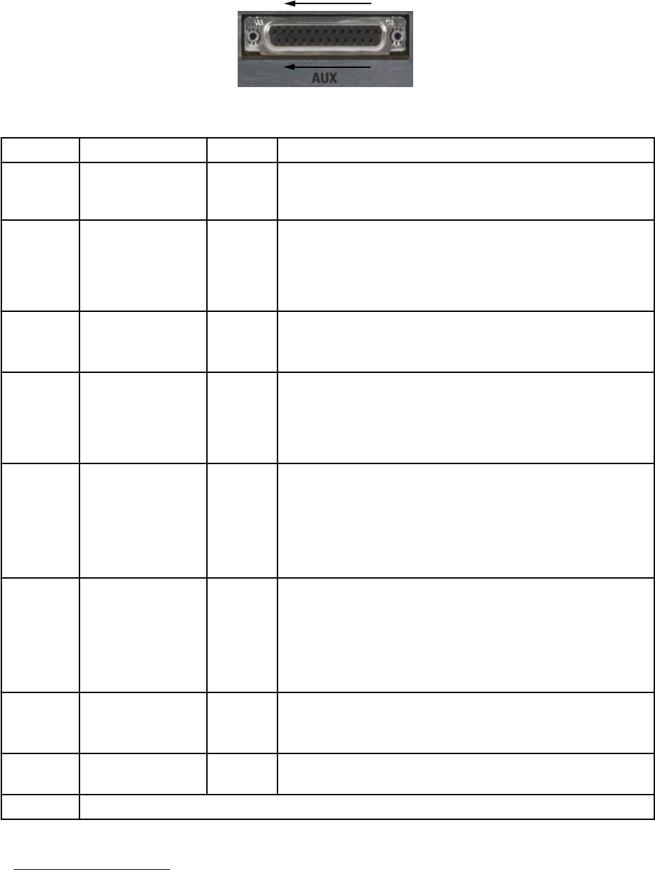
Figure 32: Auxiliary Connector
14
25
1
13
Table 32: Auxiliary Connector
Location Pin Assignment Type Signal Characteristics
1 Tx Audio 1 Audio Transmit Audio – Nominal input level is 80 mVrms for 60%
deviation with scaling factor set to 100%. 600 Ω input impe-
dance.
2 GPIO 1 Digital Output Logic Low: 0.5 VDC max
Output Logic High: Open Collector with 10 k pull-up to 5 V
Input Logic Low: 0–0.8 VDC
Input Logic High: 3.0–14 VDC
3 Rx Audio 2 5Audio Receiver Audio – Nominal output level is 330 mVrms (into a
50 k Ohm load) with a 60% deviation receive signal.
1000 Ω output impedance.
4 GPIO 2 Digital Output Logic Low: 0.5 VDC max
Output Logic High: Open Collector with 10 k pull-up to 5 V
Input Logic Low: 0–0.8 VDC
Input Logic High: 3.0–14 VDC
5 GPIO 10/Analog
Input 2 5
Digital Output Logic Low: 0.5 VDC max
Output Logic High: Open Collector with 10 k pull-up to 5 V
Input Logic Low: 0–0.8 VDC
Input Logic High: 3.0–14 VDC
Analog: 0–5 VDC
6 GPIO 9/Analog In-
put 1 5
Digital Output Logic Low: 0.5 VDC max
Output Logic High: Open Collector with 10 k pull-up to 5 V
Input Logic Low: 0–0.8 VDC
Input Logic High: 3.0–14 VDC
Analog: 0–5 VDC
7 Rx Audio 1 Audio Receiver Audio – Nominal output level is 330 mVrms (into a
50 k Ohm load) with a 60% deviation receive signal.
1000 Ω output impedance.
8 GPIO 6 Digital Receiver Audio – Nominal output level is 330 mVrms with a
60% deviation receive signal. 1000 Ω output impedance.
9 Ground
Table continued…
5Not supported in initial release.
MN001436A01-AD
Chapter 7: SLR 5000 Series Back Panel
76 Send Feedback

Location Pin Assignment Type Signal Characteristics
10 GPIO 7/Analog
RSSI Out 5
Digital or
Analog
Digital:
Output Logic Low: 0.5 VDC max
Output Logic High: Open Collector with 10 k pull-up to 5 V
Input Logic Low: 0–0.8 VDC
Input Logic High: 3.0–14 VDC
Analog RSSI:
Typically 0.5 VDC for -120 dBm to 2.7 VDC for -60 dBm
carrier. Variation with carrier level at approximately 50 mV/
dBm.
11 GPIO 11/Analog
Input 3 5
Digital or
Analog
Digital:
Output Logic Low: 0.5 VDC max
Output Logic High: Open Collector with 10 k pull-up to 5 V
Input Logic Low: 0–0.8 VDC
Input Logic High: 3.0–14 VDC
Analog: 0–5 VDC
12 GPIO 12/Analog
Input 4 5
Digital or
Analog
Digital:
Output Logic Low: 0.5 VDC max
Output Logic High: Open Collector with 10 k pull-up to 5 V
Input Logic Low: 0–0.8 VDC
Input Logic High: 3.0–14 VDC
Analog: 0–5 VDC
13 Tx Data Digital or
Analog
Transmit Data/PL/DPL – Nominal input level is 80 mVrms
for 20% deviation with scaling factor set to 100%. 600 Ω in-
put impedance.
14 1 PPS In 5/Out Digital Output Logic Low: 0.5 VDC max
Output Logic High: Open Collector with 10 k pull-up to 5 V
Input Logic Low: 0–0.8 VDC
Input Logic High: 3.0–14 VDC
15 GPIO 3 Digital Output Logic Low: 0.5 VDC max
Output Logic High: Open Collector with 10 k pull-up to 5 V
Input Logic Low: 0–0.8 VDC
Input Logic High: 3.0–14 VDC
16
Ground
17
18
19
20 Fused B+ Power The B+ is 13.6 VDC when repeater is sourced by AC, and
can range from 11–14.4 VDC when sourced by DC. 1 A
(max).
Table continued…
MN001436A01-AD
Chapter 7: SLR 5000 Series Back Panel
Send Feedback 77
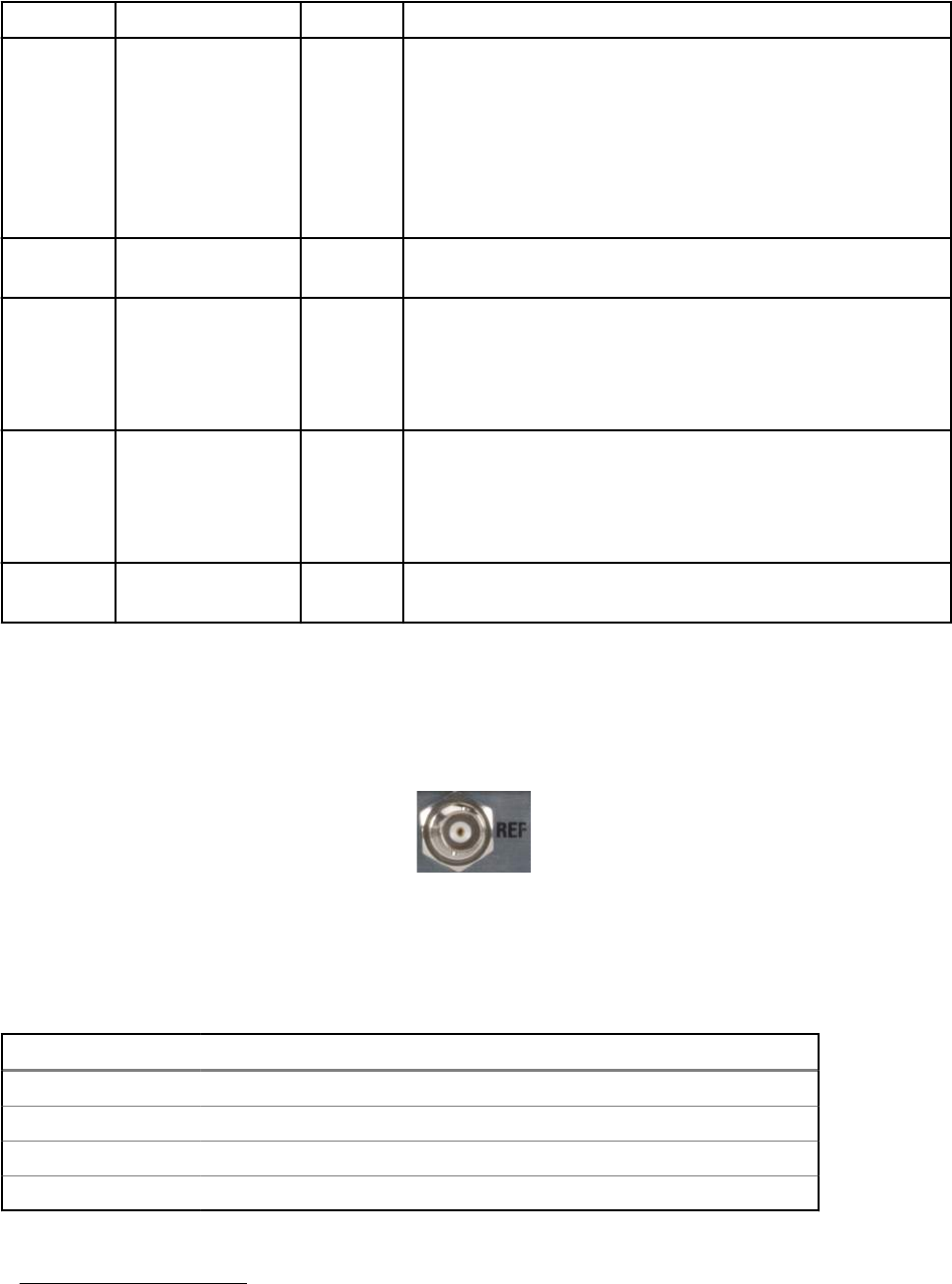
Location Pin Assignment Type Signal Characteristics
21 GPIO 8/Analog
Output 2 5
Digital or
Analog
Digital:
Output Logic Low: 0.5 VDC max
Output Logic High: Open Collector with 10 k pull-up to 5 V
Input Logic Low: 0–0.8 VDC
Input Logic High: 3.0–14 VDC
Analog: 0–5 VDC
22 Tx Audio 1 Audio Transmit Audio – Nominal input level is 80 mVrms for 60%
deviation with scaling factor set to 100%. 600 Ω input
23 GPIO 4 Digital Output Logic Low: 0.5 VDC max
Output Logic High: Open Collector with 10 k pull-up to 5 V
Input Logic Low: 0–0.8 VDC
Input Logic High: 3.0–14 VDC
24 GPIO 5 Digital Output Logic Low: 0.5 VDC max
Output Logic High: Open Collector with 10 k pull-up to 5 V
Input Logic Low: 0–0.8 VDC
Input Logic High: 3.0–14 VDC
25 Tx Audio 2 5Audio Transmit Audio – Nominal input level is 80 mVrms for 60%
deviation with scaling factor set to 100%. 600 Ω input
7.2.9
Frequency Reference
The Frequency Reference port is a BNC (female) type connector.
Figure 33: Frequency Reference Connector
Various external frequency reference signal types can be provided to the SLR 5000 series repeater for
normal operation. Table 33: Frequency Reference on page 78 provides a list of acceptable input
signal types as well as their permissible levels.
Table 33: Frequency Reference
Frequency (MHz) Waveform 6Level (Vpp) Impedance (Ω) 7Note
5 Sine 1.5–5.3 100 k AC Coupled
5 Square 61.5–5.3 100 k AC Coupled
10 Sine 1.5–5.3 100 k AC Coupled
10 Square 61.5–5.3 100 k AC Coupled
6Square wave duty cycle range is 45–50%.
7Impedance of the SLR 5000 series repeater's frequency reference port.
MN001436A01-AD
Chapter 7: SLR 5000 Series Back Panel
78 Send Feedback
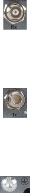
7.2.10
Receiver RF
The Receiver RF port is a BNC (female) type connector.
Figure 34: Receiver RF Connector
7.2.11
Transmitter RF
The Transmitter RF port is an N-Type (female) type connector. Figure 35: Transmitter RF Connector
on page 79 depicts the Transmitter RF connector.
Figure 35: Transmitter RF Connector
7.2.12
Bonding Ground Connection
The repeater Bonding Ground Connection is realized with an M6 x 1 x 3 mm screw (T30 Torx). Figure
36: Bonding Ground Connection on page 79 depicts the Bonding Ground Connection.
Figure 36: Bonding Ground Connection
MN001436A01-AD
Chapter 7: SLR 5000 Series Back Panel
Send Feedback 79
This page intentionally left blank.

Chapter 8
SLR 5000 Series Test Equipment And
Service Aids
8.1
Recommended Test Equipment
The list of equipment includes most of the standard test equipment required for servicing Motorola
Solutions SLR 5000 Series Repeater.
Table 34: Recommended Test Equipment
Equipment Example Application
Service Monitor Aeroflex 3920 Digital Radio Test
Set or equivalent 8
http://www.aeroflex.com
Frequency/deviation meter, signal
generator, oscilloscope, RF power
meter for wide-range trouble-
shooting, and alignment.
Digital RMS Mul-
timeter
Fluke 179 or equivalent http://
www.aeroflex.com.
AC/DC voltage measurements.
8.2
Service Aids
Service Tools on page 135 lists the service aids recommended for working on the SLR 5000 series
repeater. While all of these items are available from Motorola Solutions, most are standard workshop
equipment items, and any equivalent item capable of the same performance may be substituted for the
item listed.
8Equivalency can be established with "all-in-one" service monitors and/or the individual functional
components of a service monitor (such as RF Signal Generator, RF Spectrum Analyzer, RF De-
viation Meter, RF Power Meter, and oscilloscope).
MN001436A01-AD
SLR 5000 Series Test Equipment And Service Aids
Send Feedback 81
This page intentionally left blank.

Chapter 9
SLR 5000 Series Performance Check
or Testing
9.1
General
The SLR 5000 Series Repeater meets published specifications through the manufacturing process by
utilizing high-accuracy laboratory-quality test equipment. The recommended field service equipment
approaches the accuracy of the manufacturing equipment with few exceptions. This accuracy must be
maintained in compliance with the equipment manufacturer’s recommended calibration schedule.
NOTICE: Although these repeaters function in digital and analog modes, all testing is done in
analog mode. Digital Repeater tests can be performed using an Aeroflex 3900 Series Service
Monitor, if the DMR Digital Repeater Test Option is purchased. This auto testing could be
performed in lieu of the following Manual testing.
9.2
Transmitter Testing
CAUTION: The SLR 5000 Series Repeater needs to be taken out of service in order to carry
out performance testing procedures. Unless the repeater is already out of service, it is
recommended to perform the procedures during off-peak hours in order to minimize disruption
of service to the system subscribers.
9.2.1
Introduction
While most module faults can be detected by running the repeater diagnostics, the following procedure
provides a more traditional method of troubleshooting the transmitter circuitry.
This procedure allows the service technician to make minor adjustments and verify proper operation of
the SLR 5000 Series Repeater's transmit circuitry, including:
• Exciter Section of Modem Module
• Power Amplifier Module
• Power Supply Module
In general, the transmitter circuitry is exercised by injecting and measuring signals using a Service
Monitor (or equivalent). Incorrect measurement values indicate a faulty module(s); measurement
values within the acceptable range verify proper operation of the listed modules and circuitry.
9.2.2
Test Equipment
The following test equipment are required to perform the procedure:
• Aeroflex 3920 Digital Radio Test Set (or equivalent)
• Microphone (GMMN4063_)
• Power Meter and Sensor
• Station Rear Accessory Test Cable
MN001436A01-AD
SLR 5000 Series Performance Check or Testing
Send Feedback 83
• Dummy Load (50 Ω, repeater wattage or higher)
9.2.3
Verifying Transmitter Circuitry Procedure
Procedure:
1Connect and set up test equipment as shown in Figure 37: Test Equipment Setup for Verifying
Transmitter Circuitry on page 85.
2Apply input power (AC or DC) to the repeater. The power supply, modem, and PA fans should
run a few seconds to confirm fan operation.
3Press the PTT switch of the microphone and observe the PA Keyed LED indicator on the
Repeater Front Panel.
If PA Keyed fails to light, suspect the following:
• Faulty Power Amplifier Module
• Faulty Modem Module
• Loose or bad Exciter-to-PA RF cable
• Loose or bad PA-to-antenna RF output cable
• Improperly terminated PA RF output cable
• Faulty Power Supply Module
4Measure output power by pressing the PTT button and observing reading on an in-line
wattmeter.
• If PA output is not at proper power (as set for particular site), adjust the output power as
described in the CPS online help.
5If PA output power is proper, set up the Service Monitor for spectrum analyzer display. Press the
PTT button and observe the display. The display should show a single frequency carrier:
• If the display shows multiple carriers evenly spaced about the carrier, suspect a faulty Exciter
module or PA module.
• If the display shows a solid carrier but it is off frequency, suspect the following:
• Faulty Modem Module
• Faulty external 5/10 MHz reference source (if used)
• If the display shows a single carrier moving erratically, suspect a faulty Modem Module.
6If display is proper, set up Aeroflex 3900 Series Communications System Analyzer to display
modulation. Using the microphone, push the PTT button and speak into the microphone. Verify
that the display shows an audio signal.
• If the proper display is not obtained, suspect faulty SCM or Exciter Module
7Set the Aeroflex 3900 Series Communications System Analyzer for GEN/MON MTR. Press the
PTT button and speak loudly into the microphone to cause maximum deviation. Display should
read:
• 4.60 kHz maximum for a 25 kHz system
• 3.68 kHz maximum for a 20 kHz system
• 2.30 kHz maximum for a 12.5 kHz system
If the proper display is not obtained, suspect faulty SCM or Exciter Module.
8This completes the Verifying Transmitter Circuitry test procedure. If all displays and
measurements are correct, the transmitter circuitry may be considered to be operating properly.
MN001436A01-AD
Chapter 9: SLR 5000 Series Performance Check or Testing
84 Send Feedback
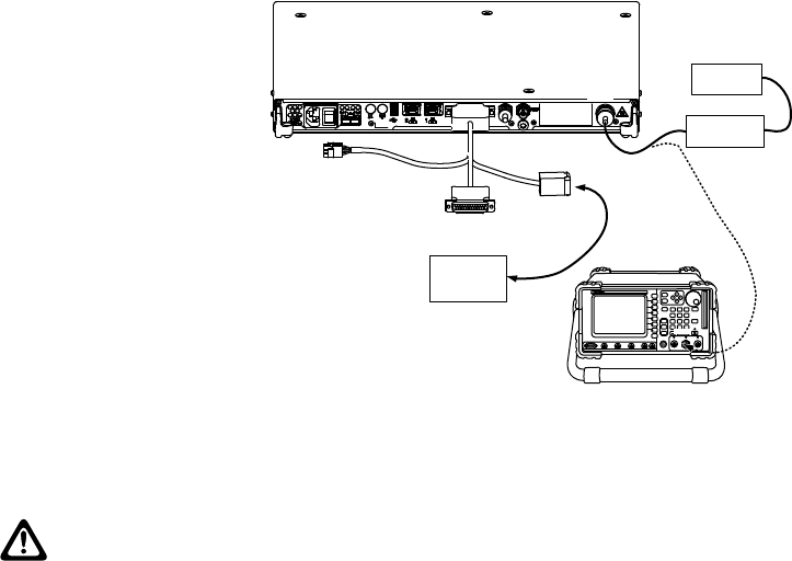
Figure 37: Test Equipment Setup for Verifying Transmitter Circuitry
HELP TAB
1
SELECT
CANCEL
IFR390I Digital Radio Test Set
TEST HOLD
CONFIG
UTILS ENTER
MIC/ ACC GEN T/R ANT
RETURN
TESTPORT CH1SCOPECH2 1 2AUDIOINFCTNGEN/DEMODOUT
0.
#
ASSIGN
–
*
2
4 5 6
7
HELP
8 9
3
T/R
Power Meter
Dummy Load
Tx
(Step 5)
Microphone
(GMMN4063_)
9.3
Receiver Testing
CAUTION:
Performing this procedure requires that the repeater be taken out of service. It is recommended
that, unless the SLR 5000 Series Repeater is already out of service, this procedure be
performed during
off-peak hours so as to minimize the disruption of service to the system subscribers.
If the repeater operates as a repeater, the transmit output from the repeater must be connected
to a dummy load to prevent over-the-air broadcast during Receiver testing.
9.3.1
Introduction
While most module faults can be detected by running the SLR 5000 Series Repeater diagnostics, the
following procedure provides a more traditional method of troubleshooting the Receiver circuitry.
This procedure allows the service technician to make minor adjustments and verify proper operation of
the receiver circuitry on the Modem Module.
In general, the Receiver circuitry is exercised by injecting and measuring signals using a Service
Monitor (or equivalent). Incorrect measurement values indicate a faulty module(s); measurement
values within the acceptable range verify proper operation of the receiver circuitry on the Modem
Module.
9.3.2
Required Test Equipment
The following test equipment are required to perform the procedure:
• Aeroflex 3920 Digital Radio Test Set (or equivalent)
• Service Speaker (part no. HSN1006_)
• Station Rear Accessory Test Cable
• Dummy Load (50 Ω, repeater wattage or higher) required for repeaters only
MN001436A01-AD
Chapter 9: SLR 5000 Series Performance Check or Testing
Send Feedback 85
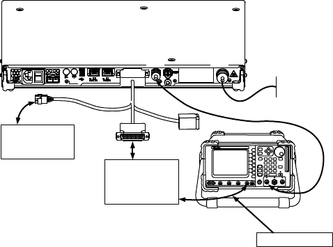
9.3.3
Verifying Receiver Circuitry Procedure
Procedure:
1Connect equipment as shown in Figure 38: Test Equipment Setup for Verifying Receiver
Circuitry on page 86.
2Set the Service Monitor to generate a 1.0 μV (-107 dBm) FM signal at the Receiver frequency,
modulated by a 1 kHz tone at 3 kHz deviation for 25/30 kHz channel spacing, or 1.5 kHz
deviation for 12.5 kHz channel spacing. The 1 kHz tone should be audible through the external
speaker. If no audio is heard, suspect the following:
• Faulty Modem Module
• Faulty antenna-to-Receiver preselector RF cable (for the repeater with external metal
preselector)
• Faulty Service Monitor-to-station RF cable
• Faulty Antenna Relay (If installed)
• Faulty Preselector (If installed)
• Rear Panel to Modem Module cable unplugged
• Faulty rear panel to Modem Module Cable
3If Audio is heard (the audio volume can be adjusted on the rear of the HSN1006), look at the
Oscilloscope window on the Aeroflex 3920 (or a separate O-Scope) and verify that the Audio
level Sine Wave measures between 0.75 to 1.5 Vpp. If not, connect to Tuner and increase the
RX Audio level until this is achieved. If the level cannot be obtained, suspect a faulty Modem.
4Move the BNC cable from the Scope CH 1 input to the Audio 1 input.
5Change System Monitor injection signal level to the noted levels in .
6Measure the Receiver 12 dB SINAD sensitivity.
• If the SINAD level is less than 12 dB, suspect faulty Modem.
7This completes the Verifying Receiver Circuitry test procedure. If all displays and measurements
are correct, the Receiver circuitry may be considered to be operating properly. Remove test
equipment, restore the repeater to normal service, and (if applicable) return to the
troubleshooting flow chart to resume troubleshooting sequence.
Figure 38: Test Equipment Setup for Verifying Receiver Circuitry
HELP TAB
1
SELECT
CANCEL
IFR390I Digital Radio Test Set
TEST HOLD
CONFIG
UTILS ENTER
MIC/ ACC GEN T/R ANT
RETURN
TESTPORT CH1 SCOPE CH2 1 2AUDIOINFCTNGEN/DEMOD OUT
0.
#
ASSIGN
–
*
2
4 5 6
7
HELP
8 9
3
GEN
Test Box (RLN4460_)
Service Speaker
(HSN1006_)
Aud 1
MT B+
Dummy Load
TxRx
Connect to Scope Ch 1
MN001436A01-AD
Chapter 9: SLR 5000 Series Performance Check or Testing
86 Send Feedback

9.4
Auto Test and Tune Support
Auto Test and Tune Support is an automated alignment procedure for the repeater.
This procedure allows you to perform Test and Tune in the right method that saves time and helps to
achieve higher efficiency.
To accomplish the overall Test and Tune procedure, the repeater must be tested in two test suites:
Analog mode and Digital mode. This procedure includes Tuning and Testing in Analog mode and
Testing in Digital mode.
NOTICE: Contact Motorola Solutions Customer Support for more details on this procedure.
MN001436A01-AD
Chapter 9: SLR 5000 Series Performance Check or Testing
Send Feedback 87
This page intentionally left blank.
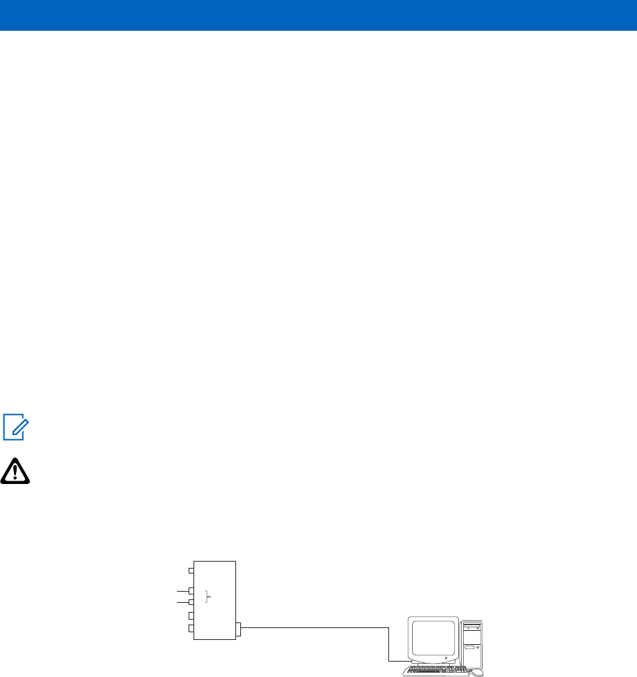
Chapter 10
SLR 5000 Series Programming and
Tuning
10.1
Introduction
This chapter provides an overview of the MOTOTRBO Customer Programming Software (CPS) and
the MOTOTRBO Tuner application for use on Windows 7™, Windows 8™, or Windows 8.1™. These two
MOTOTRBO applications are used for the configuration and alignment of the SLR 5000 Series
Repeater.
10.2
Customer Programming Software Setup
The Customer Programming Software setup, shown in Figure 39: Customer Programming Software
Setup on page 89 is used to program the repeater. See Figure 40: Front view of SLR 5000 Series
Repeater on page 90 and Figure 41: Rear view of SLR 5000 Series Repeater on page 90 for the
actual connectors on the front and rear panels of the repeater.
NOTICE: See appropriate program on-line help files for the programming procedures.
CAUTION: Computer USB ports can be sensitive to Electronic Discharge. Employ proper ESD
practices (wrist strap, grounding, etc.) and do not touch exposed contacts on cables when
connected to a computer.
Figure 39: Customer Programming Software Setup
Front Panel
USB
AC
USB
120 / 240 VAC
Station
Tx Port
(N-type Female)
Rx Port
(BNC Female)
AUX
DC
13.6 VDC
Standard Type “A” to Type “B” USB cable
Rear Panel
Either
One or Both
MN001436A01-AD
SLR 5000 Series Programming and Tuning
Send Feedback 89
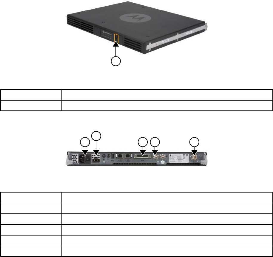
Figure 40: Front view of SLR 5000 Series Repeater
1
Table 35: Callout Legend
Label Description
1 USB Port
Figure 41: Rear view of SLR 5000 Series Repeater
1
2
3 4 5
Table 36: Callout Legend
Label Description
1 AC Inlet Connector
2 DC Inlet Connector
3 Aux Connector
4 Rx RF Connector
5 Tx RF Connector
10.3
Reference Oscillator Alignment
This feature is used to adjust the reference oscillator of the repeater. This alignment process should be
done as maintenance schedules and regulations require or if the Modem FRU has been replaced in
the repeater.
10.3.1
Tuning the Reference Oscillator Alignment
Procedure:
1Connect the repeater’s transmitter antenna port to the Communication Analyzer.
2Power the repeater from either an AC or DC source.
3Launch the Tuner application.
MN001436A01-AD
Chapter 10: SLR 5000 Series Programming and Tuning
90 Send Feedback
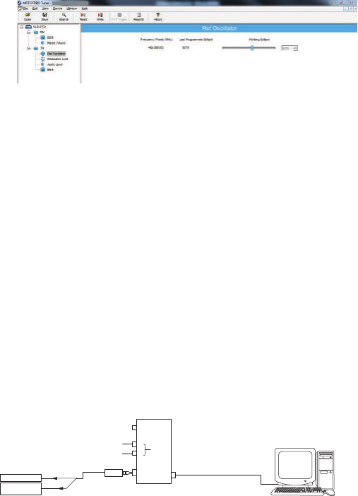
4To begin reading the repeater’s tuning softpot values, click Read.
5Under the TX menu in the tree view, select Ref Oscillator. (See Figure 42: Tx Menu Tree (Ref.
Oscillator) on page 91).
Figure 42: Tx Menu Tree (Ref. Oscillator)
6Configure the current operating frequency into the Communications Analyzer.
7To key up the repeater, click PTT Toggle.
8Adjust the working softpot value until the frequency is within the performance specifications (+/-
40 Hz for UHF and VHF) from the frequency point.
9To de-key the repeater, click PTT Toggle.
10 To save the tuned softpot value into the repeater codeplug, click Write.
10.4
Repeater Tuning Setup
A personal computer (PC), Windows TM operating system, and the MOTOTRBO Tuner application are
required to align the repeater. To perform the tuning procedures, the repeater must be connected to
the PC and test equipment setup as shown in Figure 43: SLR 5000 Series Repeater Tuning Equipment
Setup on page 91.
Figure 43: SLR 5000 Series Repeater Tuning Equipment Setup
Transmit
Service Monitor
or Counter
Wattmeter 20 dB Pad
Front Panel
AC
USB
120 / 240 VAC
Station
Tx Port
(BNC Female)
AUX
DC
13.6 VDC
Either
One or Both
Rear Panel
Standard Type “A” to
Type “B” USB cable
USB
10.5
Rx Audio Level Set
The procedure outlined in this section is used to set the receive output audio level from the repeater for
a given RF deviation of the received RF signal. Perform this procedure any time the Rx audio level
needs adjustment.
10.5.1
Tuning the Rx Audio Level Set
Procedure:
1Connect the repeater's receiver antenna port to the Communication Analyzer.
2Power the repeater from either an AC or DC source.
3Launch the Tuner application.
4To read the softpot values, click Read.
5Under the RX menu in the tree view, select Rx Rated Volume.
MN001436A01-AD
Chapter 10: SLR 5000 Series Programming and Tuning
Send Feedback 91
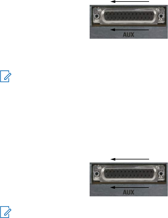
Figure 44: Rx Menu tree (Rx Rated Volume)
14
25
1
13
6Set the Communication Analyzer to output a -47 dBm RF signal modulated with a 1 kHz tone at
60% of full deviation on the tuning frequency. The tuning frequency is the value displayed on the
Tuner GUI under the heading of "Frequency Points".
NOTICE:
The Tuner aligns this parameter in a 12.5 kHz channel spacing, so 60% is 1.5 kHz of
deviation. If the CPS is set for 25 kHz operation, the repeater automatically scales the
deviation by a factor of two when it is outside the Tuner application.
Programmed TPL and DPL squelch requirements are automatically disabled for the
tuning frequency while in the Tuner application.
7Adjust the softpot value until the desired receive audio level is achieved at pin #7 (in reference to
ground) on the Aux connector Ground connections provided by the Aux connector are pins: 9,
16, 17, 18, and 19.
Figure 45: Auxiliary Connector
14
25
1
13
NOTICE: Optimally, it is recommended to load pin #7 with application loading used
during normal operation of the repeater.
8To save the new tuned softpot value into the repeater's codeplug, click Write.
10.6
Tx Audio Level Set
The procedure outlined in this section is used to allow adjustment of the transmitter audio level the
repeater is expecting at its Aux connector. Adjusting this level set has the effect of increasing or
decreasing RF signal deviation for a given transmit audio level. Perform this procedure any time the
transmitter audio level needs adjustment.
10.6.1
Tuning the Tx Audio Level Set
Procedure:
1Connect the repeater’s transmitter antenna port to the Communication Analyzer.
2Power the repeater from either an AC or DC source.
3Apply a 1 kHz signal at the desired input level to pin #1 or #22 (in reference to ground) on the
Aux connector. Ground connections provided by the Aux connector are pins: 9, 16, 17, 18, and
19. See Figure 45: Auxiliary Connector on page 92.
MN001436A01-AD
Chapter 10: SLR 5000 Series Programming and Tuning
92 Send Feedback
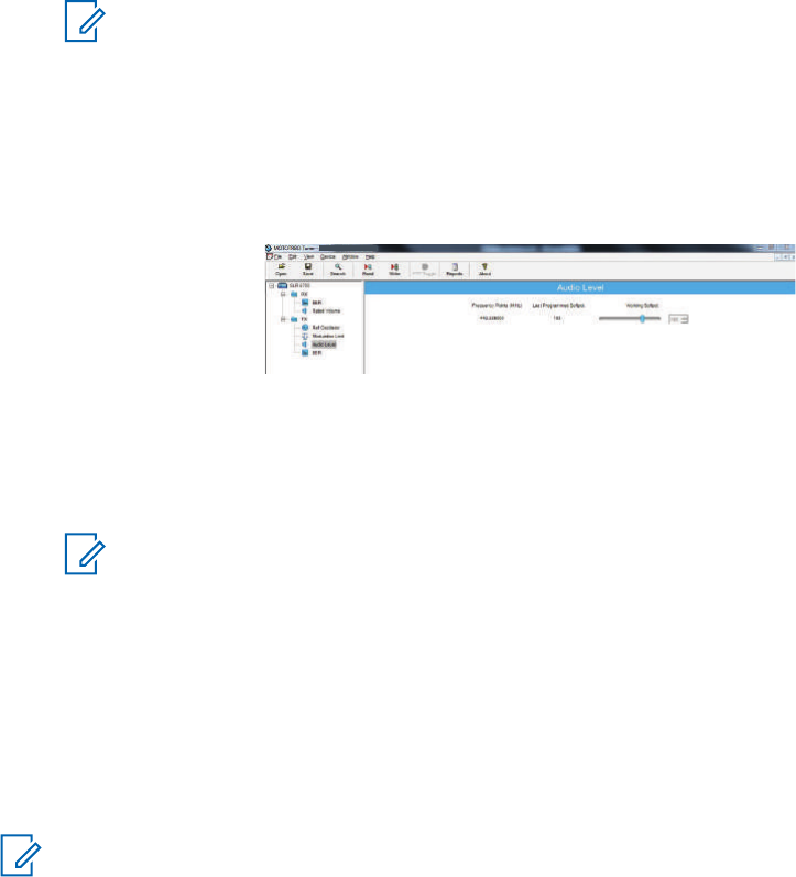
NOTICE: Optimally, it is recommended to load pin #1 or #22 with the application source
impedance used during normal operation of the repeater.
4Launch the Tuner application.
5To read the softpot values, click Read.
6Under the TX menu in the tree view, select Tx Audio Level. (See Figure 46: Tx Menu Tree (Tx
Audio Level) on page 93).
Figure 46: Tx Menu Tree (Tx Audio Level)
7Enter the tuning frequency into the Communication Analyzer (the value displayed on the Tuner
GUI under the heading of “Frequency Points”).
8To key up the repeater, click PTT Toggle.
9Adjust the softpot value until 60% of the rated system deviation (RSD) is achieved.
NOTICE: The Tuner aligns this parameter in a 12.5 kHz channel spacing, so 60% is 1.5
kHz of deviation. If the CPS is set for 25 kHz operation, the repeater automatically scales
the deviation by a factor of two when it is outside the Tuner application.
10 To de-key the repeater, click PTT Toggle.
11 To save the new tuned softpot value into the repeater’s codeplug, click Write.
10.7
Modulation Limit Alignment
This feature is to set the modulation limit of the SLR 5000 Series Repeater.
NOTICE: A modulation limit alignment is not needed if the repeater is used in repeat mode.
This is always the case when the repeater is in digital mode.
10.7.1
Tuning the Modulation Limit (with no Tx Data and no PL)
Prerequisites: If data or PL signaling is applied to Pin 13 of the Aux connector, proceed to Tuning the
Modulation Limit (with Tx Data or PL) on page 95.
Procedure:
1Connect the repeater's antenna port to the attenuation pad, if necessary, before connecting to
the Communication Analyzer.
2Power the repeater from either an AC or DC source.
3Apply a 1 kHz signal at 1.2 Vrms to Pin 1 of the Aux connector.
• Signal ground is Pin 9 of the Aux connector.
4Launch the Tuner application.
5To read the softpot values, click Read.
6Under the TX menu in the tree view, select Modulation Limit.
MN001436A01-AD
Chapter 10: SLR 5000 Series Programming and Tuning
Send Feedback 93
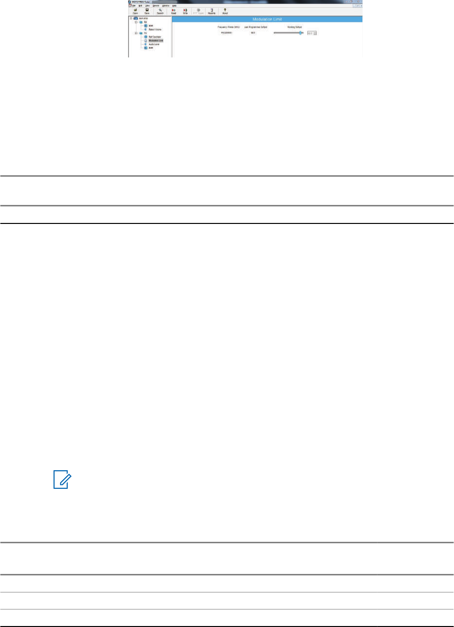
Figure 47: TX Menu Tree (Tuning Procedure with No Tx Data)
7Enter the tuning frequency into the Communication Analyzer (the value displayed on the Tuner
application).
8To key up the repeater, click PTT Toggle.
9Adjust the softpot value until the maximum deviation is 92% of the rated system deviation
(RSD). This is tested in a 12.5 kHz channel spacing, so 92% of 2.5 kHz is 2.3 kHz.
10 Set the modulation limit to 92% so that any additional deviation incurred by the transmitter VCOs
over temperature is compensated for.
Channel Spacing
(kHz)
RSD (kHz) 92% of RSD (kHz) Tolerance (Hz)
12.5 2.5 2.3 +0/ -50
11 To de-key the repeater, click PTT Toggle
12 To save the new tuned softpot value into the repeater's codeplug, click Write.
10.7.2
Verifiying the Modulation Limit (with no Tx Data and no PL)
Procedure:
1Connect the repeater's antenna port to the attenuation pad, if necessary, before connecting to
the Communication Analyzer.
2Power the repeater from either an AC or DC source.
3In CPS, program the repeater with any frequency within the specified range of the repeater
under test, and set the repeater for low power and disable the repeat path.
4Apply a 1 kHz signal at 1.2 Vrms to Pin 1 of the Aux connector.
• Signal ground is Pin 9 of the Aux connector.
5Key up the repeater and measure the deviation
• Key the repeater by grounding Pin 2 of the Aux connector.
NOTICE: CPS must have Pin 2 configured as an active low with the PTT function.
6De-key the repeater.
The deviation shall meet the limits shown in the following table.
Channel Spacing
(kHz)
Relative Standard Deviation (RSD)
(kHz)
92% of RS
(kHz)
Tolerance
(Hz)
12.5 2.5 2.3 +0/-50
20.0 4.0 3.68 +0/-80
25.0 5.0 4.6 +0/-100
MN001436A01-AD
Chapter 10: SLR 5000 Series Programming and Tuning
94 Send Feedback
NOTICE:
• The repeater is factory-tuned in accordance to this procedure and specification.
• Verification is performed outside of the Tuner application, such as in normal mode.
10.7.3
Tuning the Modulation Limit (with Tx Data or PL)
Procedure:
1Connect the repeater's antenna port to the attenuation pad, if necessary, before connecting to
the Communication Analyzer.
2Turn on the repeater using an AC or DC source.
3Launch the Tuner application.
4To read the softpot values, click Read
5Under the TX menu in the tree view, select Modulation Limit.
6Enter the tuning frequency into the Communication Analyzer (the value displayed by the Tuner
application).
7To key up the repeater, click PTT Toggle.
8Apply a 1 kHz signal at 1.2Vrms to Pin 22 of the J7 backplane connector.
• Signal ground is Pin 9 of the J7 backplane connector.
• If the manufacturer of the third party controller specifies that the Tx Audio is not to be
pre-emphasized, use Pin 1 instead of Pin 22.
9Adjust the Modulation Limit softpot to a value that limits the maximum deviation to "X"% RSD,
where "X" is equal to "92% RSD" minus "Tx Data's % RSD".
If Tx Data deviation is equal to 17%,
X = 92% - 17% = 75% as the maximum deviation limit.
Figure 48: Example of Maximum Deviation Limit Calculation
Buffer
Data or PL
Voice
8%
17%
75%
92%
0%
100%
%RSD
With Tx Data or PL
10 To de-key the repeater, click PTT Toggle .
11 To save the newly tuned softpot value into the codeplug, click Write.
12 Alignment is complete.
MN001436A01-AD
Chapter 10: SLR 5000 Series Programming and Tuning
Send Feedback 95

NOTICE:
• See Figure 10: Audio Block Diagram on page 56 for details regarding the audio and
data flow.
• Set the modulation limit to 92% to compensate for any additional deviation incurred by
the transmitter VCOs over temperature.
• The Tuner application always aligns the Modulation Limit parameter in a 12.5 kHz
channel spacing regardless of the CPS setting, so calculate the tuning % RSD
accordingly. If the CPS is set for 25 kHz operation, the repeater automatically scales
the deviation by a factor of two when outside of the Tuner application.
10.7.4
Verifying the Modulation Limit (with Tx Data or PL)
See Verifiying the Modulation Limit (with no Tx Data and no PL) on page 94 with the following
exceptions:
• The same Tx data signal level determined (obtained from step 9 in Tuning the Modulation Limit
(with Tx Data or PL) on page 95), is applied to Pin 13 during the validation process.
• Pin 22 may be used instead of Pin 1, depending on the recommendation by the manufacturer of the
third party controller.
10.8
Changing to Battery Charger Only Mode
This feature allows you to change operation mode from "Normal Mode" to "Battery Charger Only"
mode.
Prerequisites: Power the repeater from an AC source and connect the system to a laptop with USB
cable. Run the MOTOTRBO Tuner application.
Procedure:
1Connect the battery to the repeater's DC connector.
2To read the softpot values, click Read.
3Under the Device Information main menu, click Battery Charger Only Mode.
The mode change procedure begins. When the mode change procedure is completed, the
display shows All functions other than the battery charger will be
disabled. Do you wish to continue?
4Do one of the following:
• Click Yes. The display shows The Unit is in battery charger only mode.
Please remove power for 15 seconds to exit.
• Click No to return to the main menu.
Power off for 15 seconds to restore full system functionality. The system only detects and
charges another battery after restoring full system functionality.
MN001436A01-AD
Chapter 10: SLR 5000 Series Programming and Tuning
96 Send Feedback

Chapter 11
SLR 5000 Series Maintenance and
Disassembly/Reassembly
11.1
Introduction
This chapter provides details about the following:
• Routine maintenance
• Preventive maintenance (inspection and cleaning)
• Safe handling of CMOS and LDMOS devices
• Disassembly and reassembly of the repeater
• Repair procedures and techniques.
11.2
Routine Maintenance
NOTICE: Clean the repeater with a soft dry cloth while in service.
The SLR 5000 Series Repeater and ancillary equipment have been designed with state-of-the-art
technology and operate under software control, thus requiring minimal routine maintenance. Virtually
all repeater operating parameters are monitored and self-corrected by the Modem and the firmware it
runs, which makes adjustments and tuning virtually unnecessary.
Provided that the equipment is installed in an area which meets the specified environmental
requirements, the only routine maintenance task required is the calibration of the repeater reference
oscillator circuit.
11.3
Preventive Maintenance
Periodic visual inspection and cleaning is recommended.
11.3.1
Inspection
Check that the external surfaces of the SLR 5000 Series Repeater are clean, and that all external
controls and connections are in order. It is not recommended to inspect the interior electronic circuitry.
11.3.2
Cleaning Procedures
The following procedures describe the recommended cleaning agents and the methods to be used
when cleaning the external and internal surfaces of the SLR 5000 Series Repeater. External surfaces
include the top cover and repeater enclosure.
Periodically clean smudges and grime from exterior enclosure. Use a soft, non-abrasive cloth
moistened in a 0.5% solution of mild dishwashing detergent and water solution. Rinse the surface
MN001436A01-AD
SLR 5000 Series Maintenance and Disassembly/Reassembly
Send Feedback 97

using a second cloth moistened in clean water, and clean any dirt or debris from the fan grill and
louvers on the front side.
NOTICE: Internal surfaces should be cleaned only when the repeater is disassembled for
service or repair.
The only factory recommended liquid for cleaning the printed circuit boards and their components is
isopropyl alcohol (100% by volume).
Cleaning Internal Circuit Boards and Components
Isopropyl alcohol (100%) may be applied with a stiff, non-metallic, short-bristled brush to dislodge
embedded or caked materials located in hard-to-reach areas. The brush stroke should direct the
dislodged material out and away from the inside of the repeater. Make sure that controls or tunable
components are not soaked with alcohol. Do not use high-pressure air to hasten the drying process
since this could cause the liquid to collect in unwanted places. Once the cleaning process is complete,
use a soft, absorbent, lintless cloth to dry the area. Do not brush or apply any isopropyl alcohol to the
top cover and repeater enclosure.
NOTICE: Always use a fresh supply of alcohol and a clean container to prevent contamination
by dissolved material (from previous usage).
11.4
Safe Handling of CMOS and LDMOS Devices
Complementary metal-oxide semiconductor (CMOS) and laterally diffused metal-oxide semiconductor
(LDMOS) devices are used in this family of stations, and are susceptible to damage by electrostatic or
high voltage charges. Damage can be latent, resulting in failures occurring weeks or months later.
Therefore, special precautions must be taken to prevent device damage during disassembly,
troubleshooting, and repair.
Handling precautions are mandatory for CMOS/LDMOS circuits and are especially important in low
humidity conditions.
DO NOT attempt to disassemble the repeater without first referring to the following CAUTION
statement.
MN001436A01-AD
Chapter 11: SLR 5000 Series Maintenance and Disassembly/Reassembly
98 Send Feedback

CAUTION: This repeater contains static-sensitive devices. Do not open the repeater unless you
are properly grounded. Take the following precautions when working on this unit:
• Store and transport all CMOS/LDMOS devices in conductive material so that all exposed
leads are shorted together. Do not insert CMOS/LDMOS devices into conventional plastic
"snow" trays used for storage and transportation of other semiconductor devices.
• Ground the working surface of the service bench to protect the CMOS/LDMOS device. We
recommend using the Motorola Solutions Static Protection Assembly (part number
0180386A82), which includes a wrist strap, two ground cords, a table mat, and a floor mat,
ESD shoes and an ESD chair.
• Wear a conductive wrist strap in series with a 100k resistor to ground. (Replacement wrist
straps that connect to the bench top covering are Motorola Solutions part number
4280385A59).
• Do not wear nylon clothing while handling CMOS/LDMOS devices.
• Do not insert or remove CMOS/LDMOS devices with power applied. Check all power
supplies used for testing CMOS/LDMOS devices to be certain that there are no voltage
transients present.
• When straightening CMOS/LDMOS pins, provide ground straps for the apparatus used.
• When soldering, use a grounded soldering iron.
• If at all possible, handle CMOS/LDMOS devices by the package and not by the leads. Prior
to touching the unit, touch an electrical ground to remove any static charge that you may
have accumulated. The package and substrate may be electrically common. If so, the
reaction of a discharge to the case would cause the same damage as touching the leads.
11.5
Disassembly
11.5.1
Disassembly – General
Station modules suspected of being faulty must be replaced with known good modules to restore the
repeater to proper operation. The following are typical procedures to remove each of the repeater
modules.
Procedure:
1Power cord (and battery backup power, if used) and all external cables must be disconnected
before opening up repeater. Label each removed cable as required to ensure it is properly
reconnected.
2Take the proper grounding precautions as stated in Safe Handling of CMOS and LDMOS
Devices on page 98.
3When disassembling repeater, retain all screws for reuse.
The following tools are required for disassembling and reassembling the repeater:
• Torque Drivers (T10, T20 and T30). See Torque Charts on page 117 for the different size
fasteners of screw torques.
• Hex Nut Drivers (16 mm, ¾ inch [19 mm])
• Needle Nose Pliers (optional)
• Torque Gauge capable of measuring torque up to 20 in-lb (2.3 N-m) within
+/- 1 in-lb (0.1 N-m)
MN001436A01-AD
Chapter 11: SLR 5000 Series Maintenance and Disassembly/Reassembly
Send Feedback 99
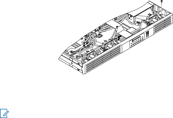
If a unit requires more complete testing or service than is customarily performed at the basic
level, send the repeater or FRU to a Motorola Solutions Service Center.
The following disassembly procedures should be performed only if necessary.
11.5.2
Disassembly – Detailed
11.5.2.1
Protective Cover Disassembly
Procedure:
1Remove the six screws on the Bottom Cover with a T10 Torx driver.
2Detach the Bottom Cover.
3Remove the six screws on the Top Cover with a T10 Torx driver.
4Detach the Top Cover.
11.5.2.2
Front Housing Disassembly
Procedure:
1Remove the three screws securing the Front Housing to the repeater chassis with a T10 Torx
driver.
2Slightly lift the Repeater and rock the Front Housing away from the chassis.
Figure 49: Removing Front Housing from Repeater
11.5.2.3
Cable Disassembly
Prerequisites:
NOTICE: When disengaging flexible cables, pull parallel to the insertion direction of the cable to
avoid damaging the cables.
Procedure:
1Disengage cable connecting Modem to Chassis ID module.
MN001436A01-AD
Chapter 11: SLR 5000 Series Maintenance and Disassembly/Reassembly
100 Send Feedback
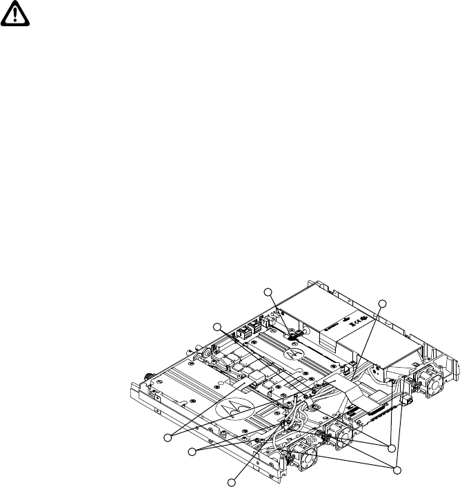
CAUTION: DO NOT attempt to remove the Chassis ID module as removing it will void
the warranty as well as disabling any purchased software features. Keep the Chassis ID
module installed throughout disassembly.
2Remove the flex cables connecting the Modem to the Power Amplifier Module and Front Panel.
3Remove the coaxial able connecting the Modem to the Power Amplifier Module.
4Gently press the locking clip and pull the “C5” connector from the Modem.
5Remove the screws from the three cable clamps securing the cables from the power supply to
the fans and modules with a T20 Torx driver and remove the cable clamps from repeater.
6Remove the two DC power screws from the Power Amplifier Module with a T10 Torx driver.
7Remove the two DC power screws from the Modem with a T10 Torx driver.
8Disengage the three connectors from the Power Supply to the three mounted fans with needle
nose pliers or fingers.
Figure 50: Removing Cables
3
1
2
4
5
6
7
8
11.5.2.4
Fan Disassembly
Procedure:
1Press the tab below the fan module until it disengages. See Figure 51: Removing Fan on page
102 for location of tab.
2Rock the fan module up and away from the frame and remove.
3Repeat the steps above for the remaining two fan modules.
MN001436A01-AD
Chapter 11: SLR 5000 Series Maintenance and Disassembly/Reassembly
Send Feedback 101
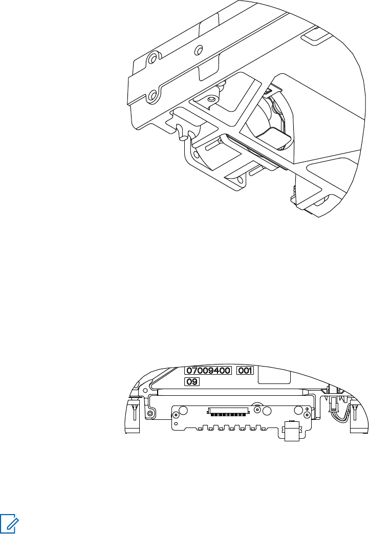
Figure 51: Removing Fan
11.5.2.5
Front Panel Disassembly
Procedure:
1Using a T10 Torx driver, remove the three screws securing the front panel to the repeater
chassis.
2Remove the Front Panel PCB from the repeater.
Figure 52: Removing Front Panel
1
23
11.5.2.6
Power Supply Removal
Prerequisites:
NOTICE: Ensure all connections from Power Supply to various parts of the repeater have been
detached.
Procedure:
1Remove the four screws securing the Power Supply Module to the repeater chassis with a T20
Torx driver.
MN001436A01-AD
Chapter 11: SLR 5000 Series Maintenance and Disassembly/Reassembly
102 Send Feedback
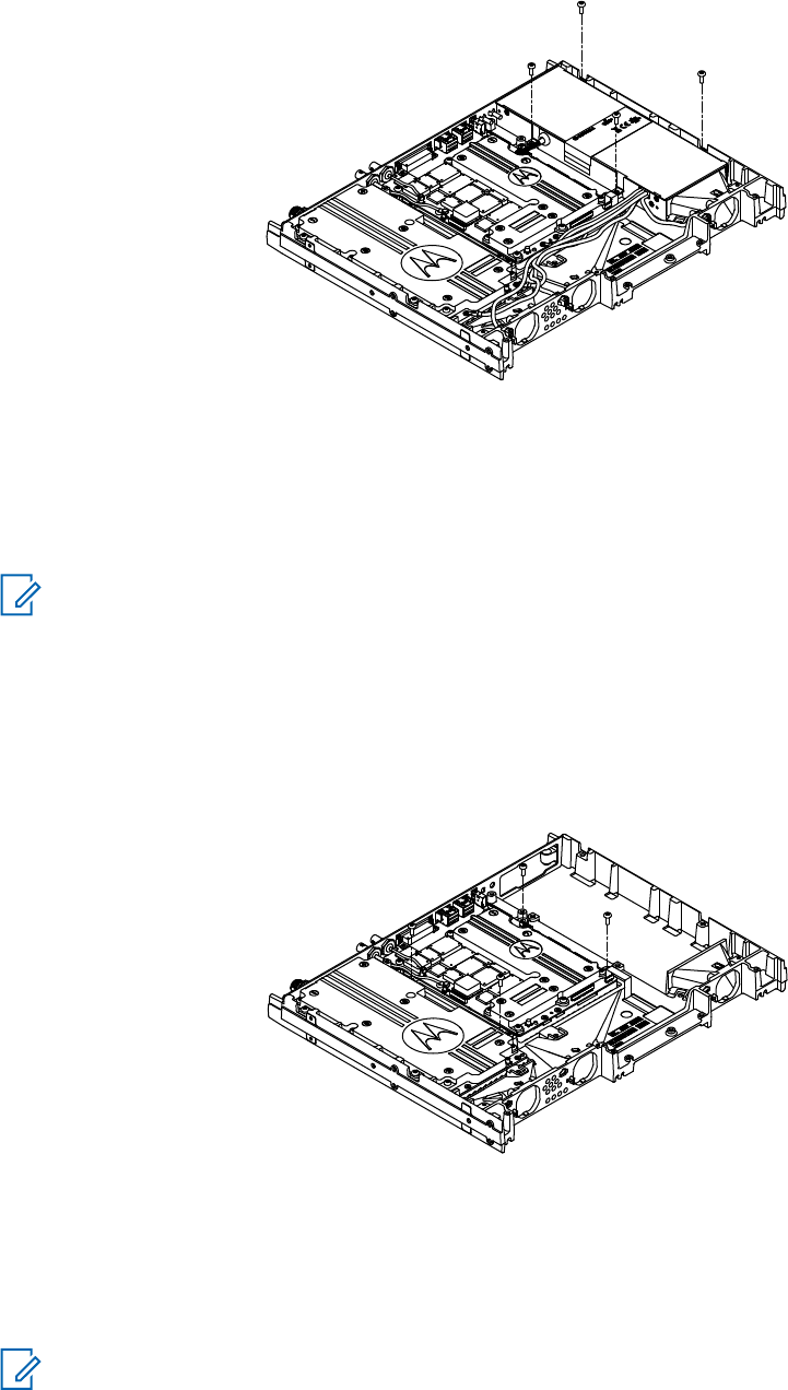
Figure 53: Removing Power Supply Module from Repeater
2Remove the Power Supply Module from the repeater.
11.5.2.7
Modem Removal
Prerequisites:
NOTICE: Ensure all connections from Power Supply to various parts of the repeater have been
detached.
Procedure:
1Detach the two coaxial cables connecting the RX Input and Reference (REF) Input connectors
to the Modem.
2Remove the four screws holding the Modem to the repeater chassis with a T20 Torx driver.
Figure 54: Removing Modem
3Remove the Modem from the repeater.
11.5.2.8
Power Amplifier Module Removal
Prerequisites:
NOTICE: Ensure all connections from Power Supply to various parts of the repeater have been
detached.
MN001436A01-AD
Chapter 11: SLR 5000 Series Maintenance and Disassembly/Reassembly
Send Feedback 103
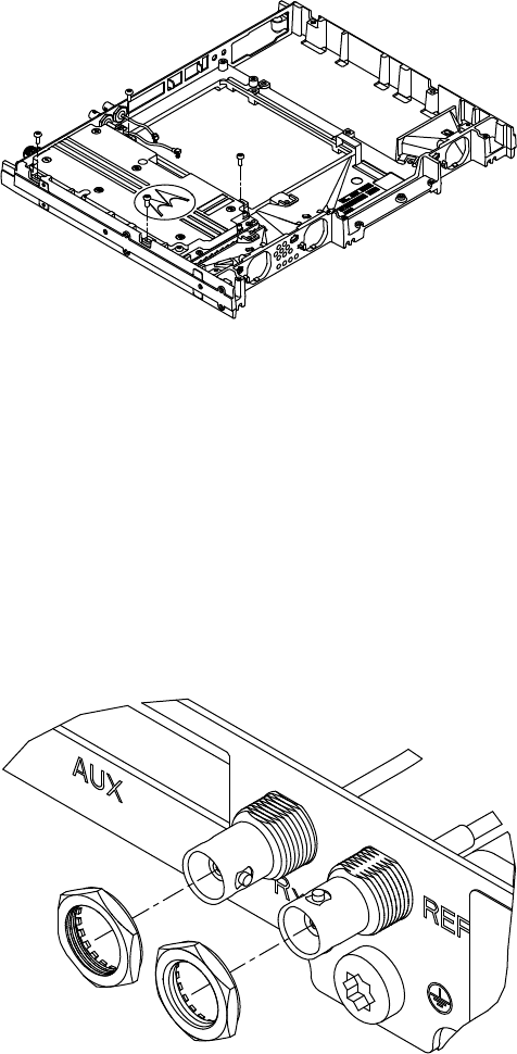
Procedure:
1Remove the nut securing the N-Type connector to the back panel on the Power Amplifier with a
0.75 in. (19 mm) hex nut driver.
2Remove the accompanying lock washer.
3Remove the four screws securing the Power Amplifier Module to the Repeater chassis with a
T20 Torx driver.
Figure 55: Removing Power Amplifier Module
4Remove the Power Amplifier Module from the Repeater.
11.5.2.9
Back Panel Removal
Procedure:
1Remove the two nuts securing the RX and Reference (REF) BNC cables to the back panel with
a 16 mm hex nut driver.
2Remove the two corresponding lock washers.
3Remove the two cables.
Figure 56: Removing Rx and REF BNC Cables
4Remove the ground screw located below the REF connector with a T30 Torx driver.
MN001436A01-AD
Chapter 11: SLR 5000 Series Maintenance and Disassembly/Reassembly
104 Send Feedback
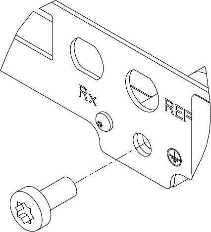
Figure 57: Removing Ground Screw
5Remove the five screws securing the back panel to the repeater chassis with a T10 Torx driver.
6Remove the back panel from the repeater.
7Remove the two rubber plugs from the back panel.
11.6
Assembly and Reassembly
11.6.1
Assembly – Detailed
11.6.1.1
Back Panel Installation
Procedure:
1Using a T10 Torx driver, install five M3 x 0.5 x 6 mm screws (PN: 0310907A18) to 10 in-lb (1.1
N-m). See Figure 58: Installing M3 Screws on page 106.
MN001436A01-AD
Chapter 11: SLR 5000 Series Maintenance and Disassembly/Reassembly
Send Feedback 105