Motorola Solutions 99FT4100 Non-Broadcast Transmitter User Manual Exhibit D Users Manual per 2 1033 c3
Motorola Solutions, Inc. Non-Broadcast Transmitter Exhibit D Users Manual per 2 1033 c3
UserManual.wiki
>
Motorola Solutions
>
99FT4100 User Manual
Exhibit D Users Manual per 2 1033 c3
Navigation menu
Upload a User Manual
Namespaces
Wiki Guide
HTML
PDF
Info
Views
User Manual
Discussion / Help
Navigation

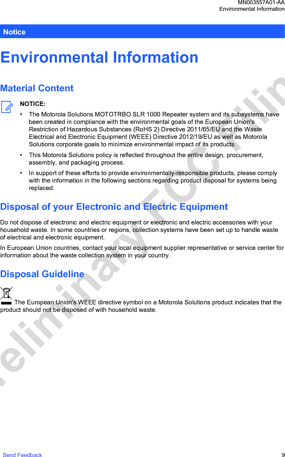
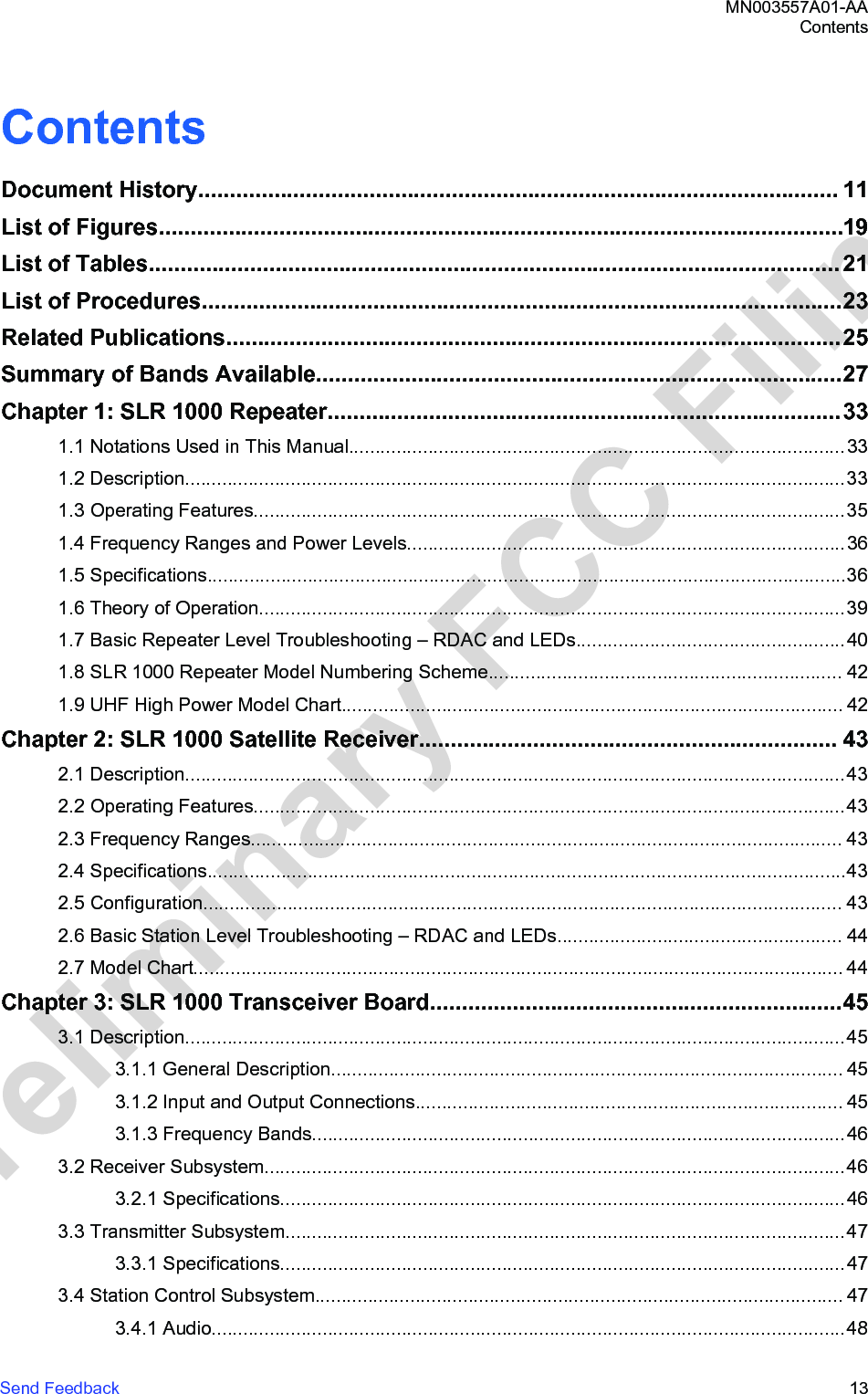

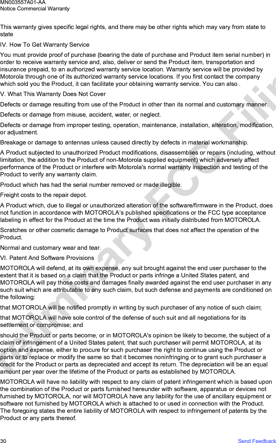
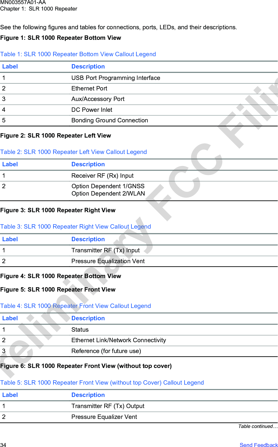
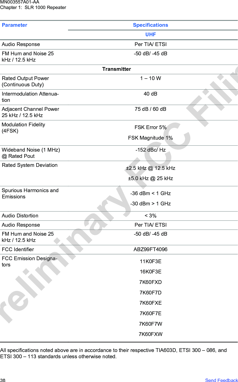
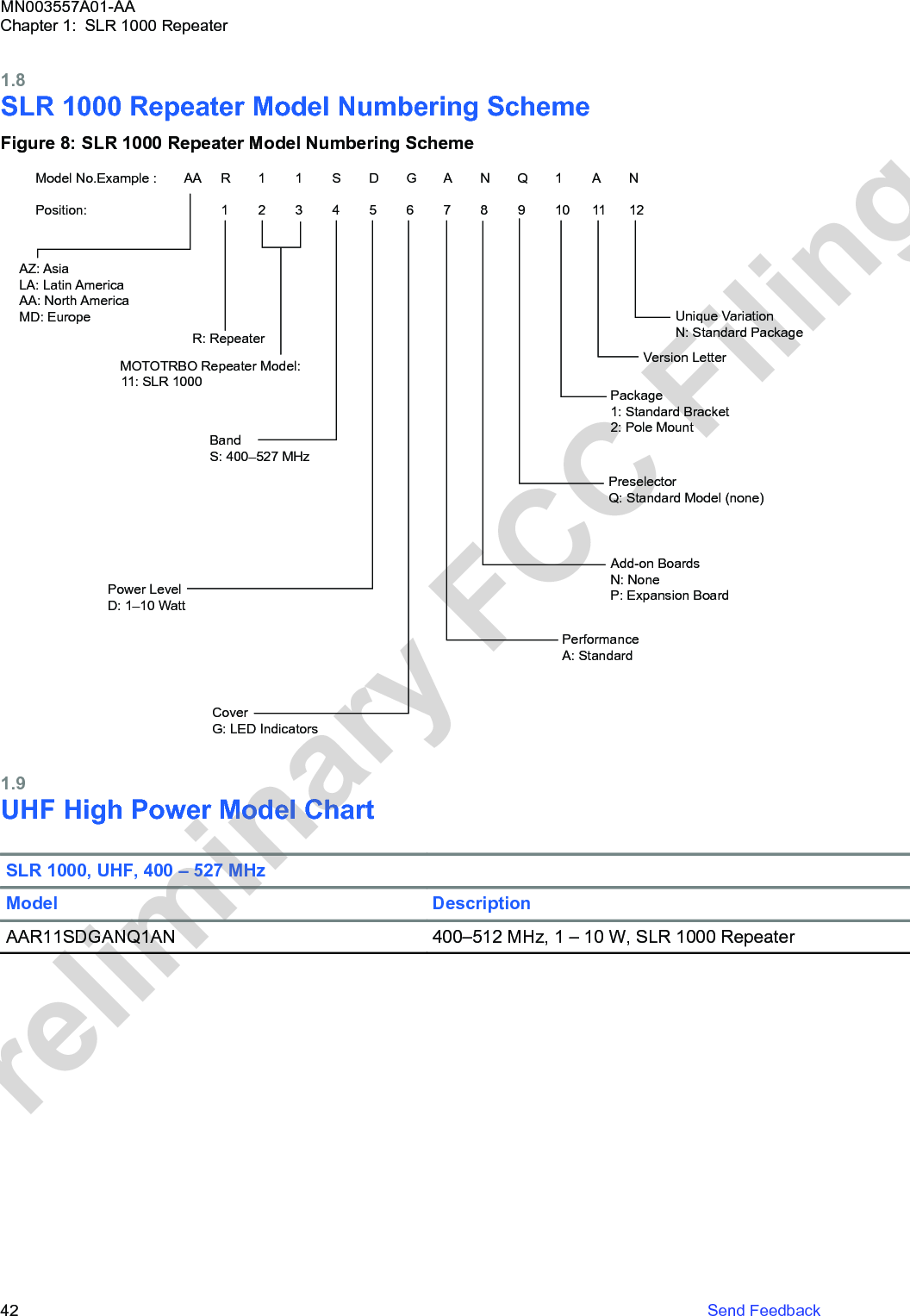
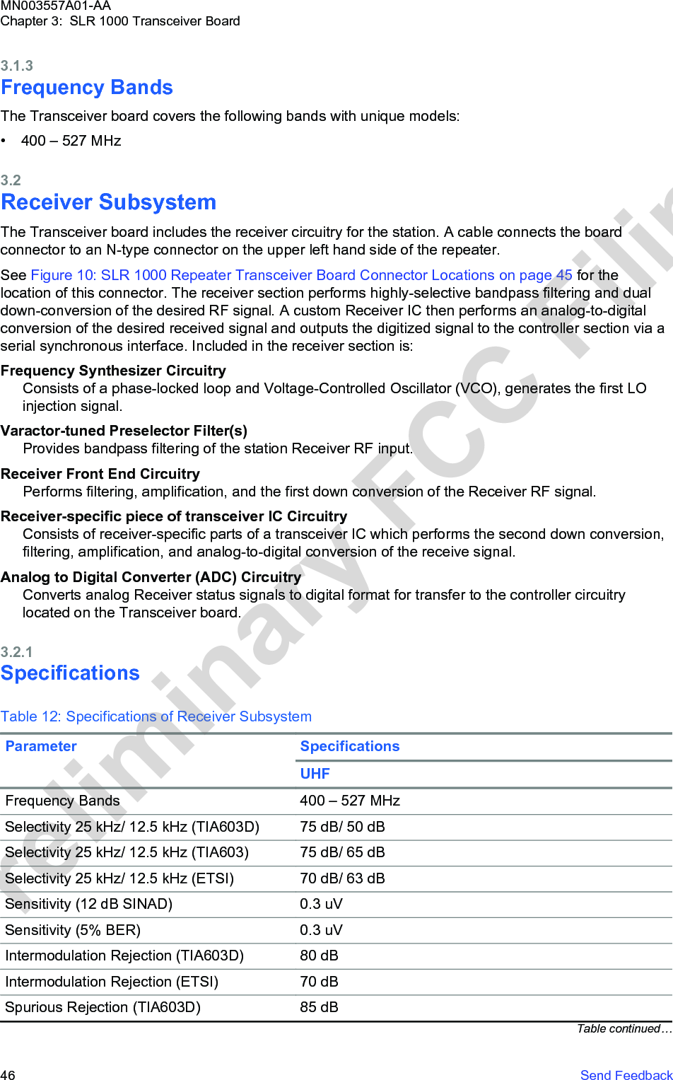
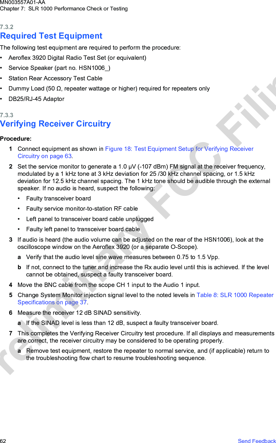
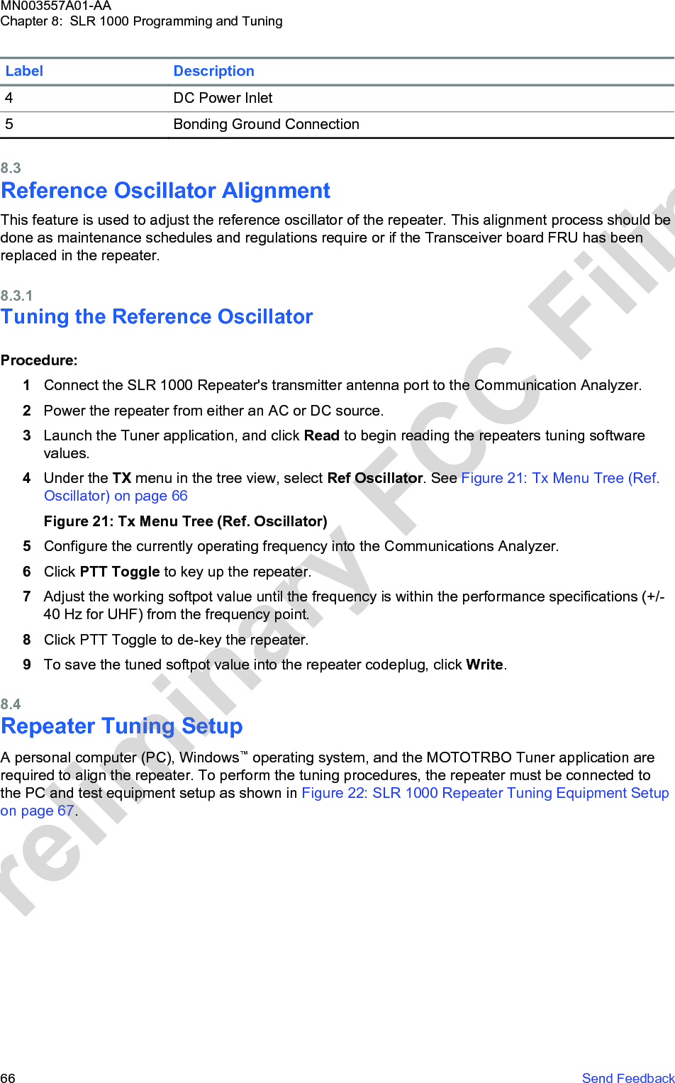
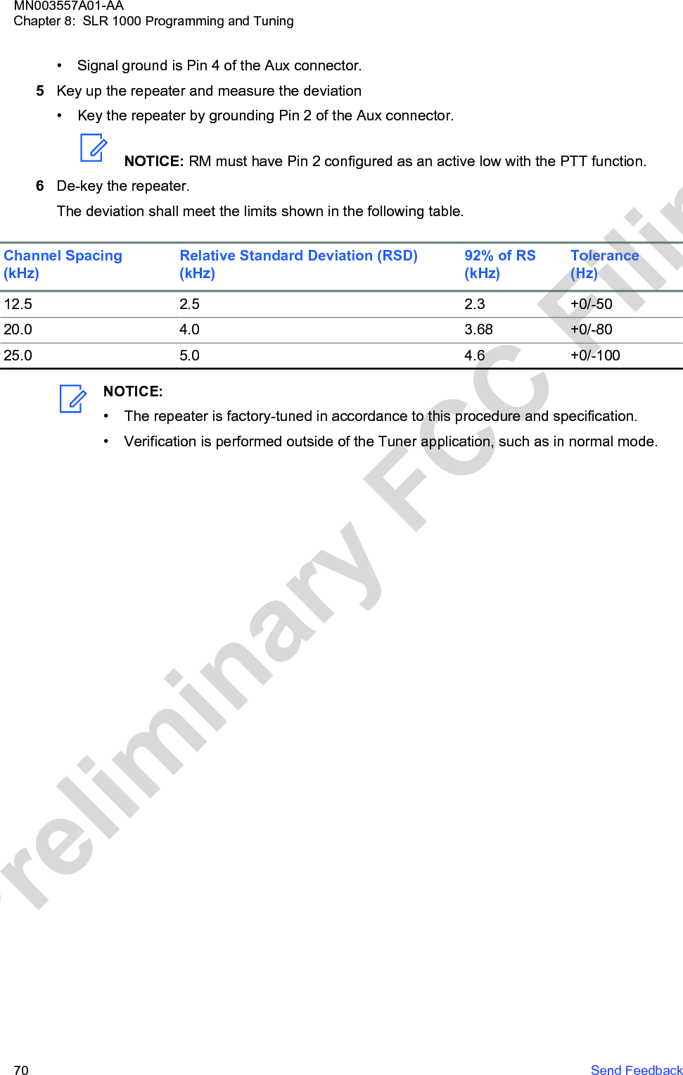
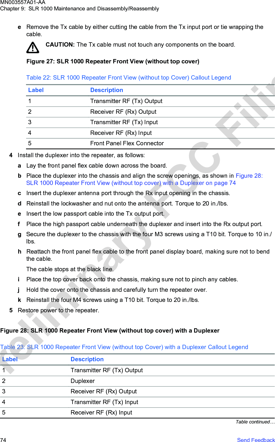
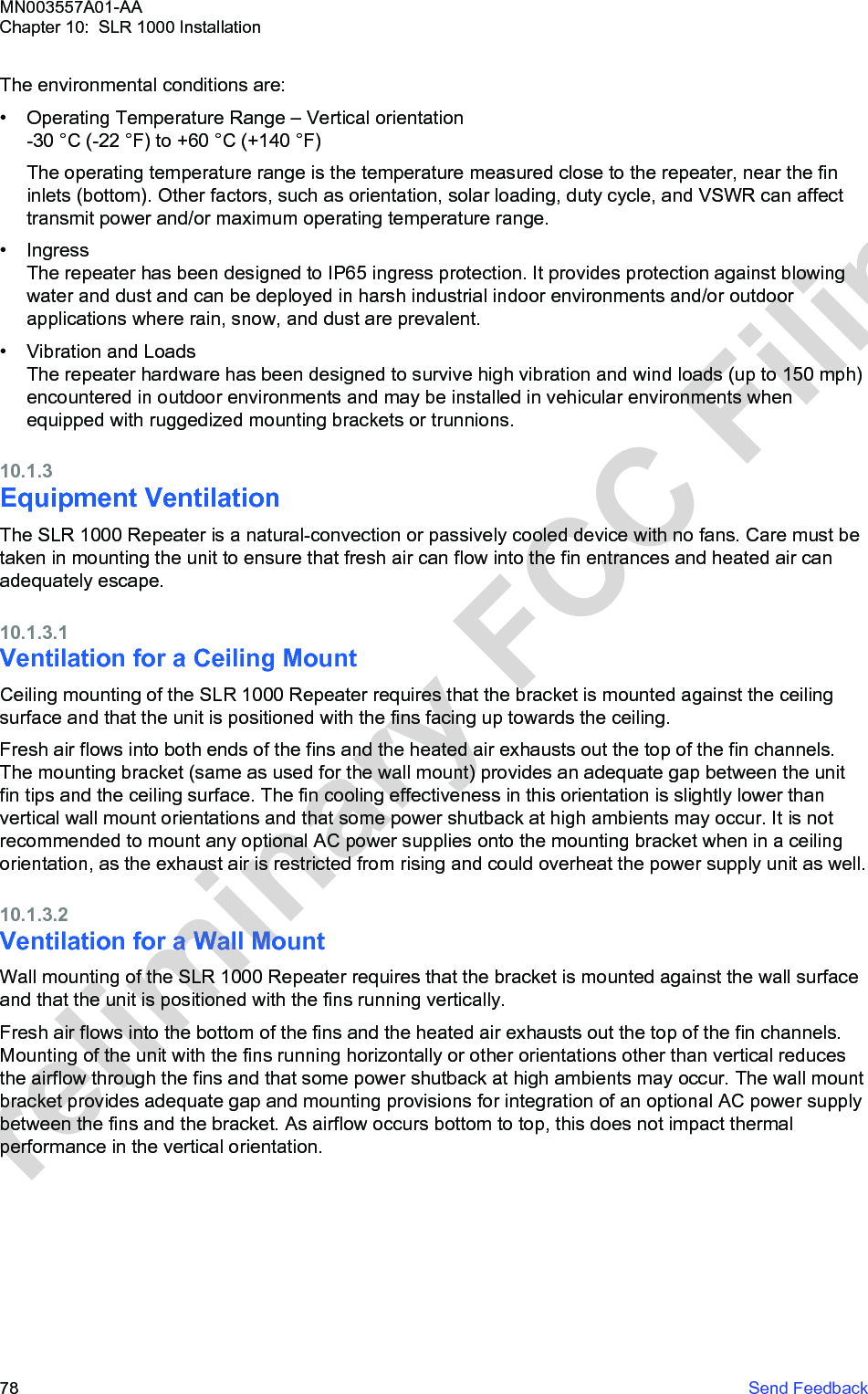
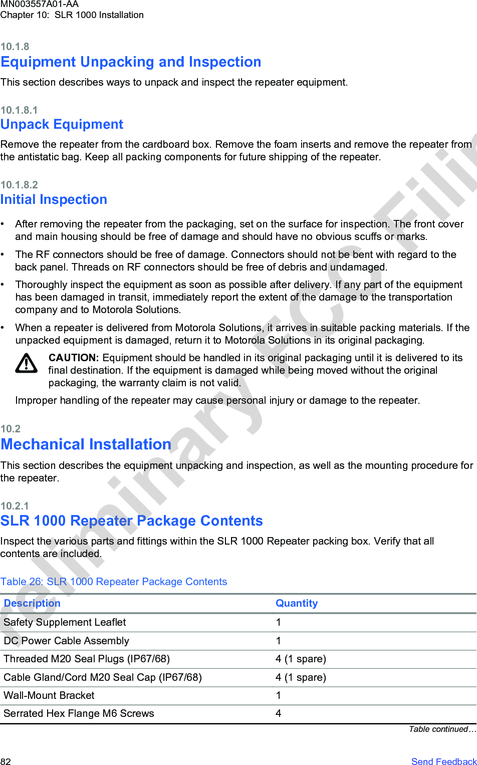
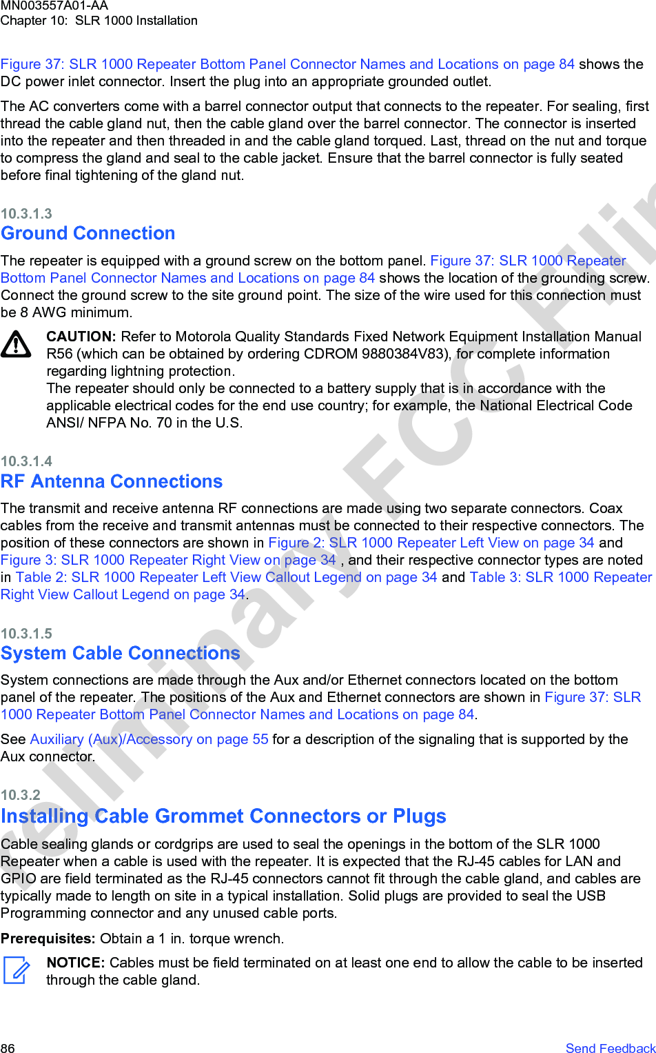
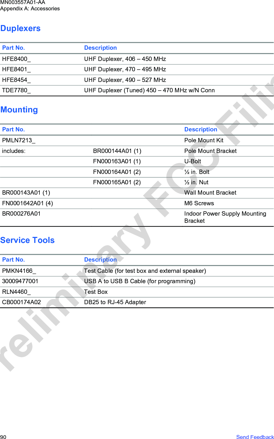


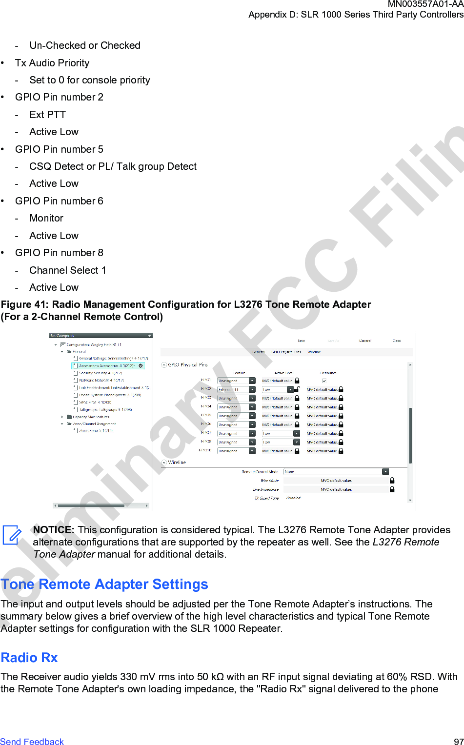
![Appendix E: MOTOTRBO RepeaterEME AssessmentNOTICE: The example in this Appendix applies for a UHF band system. For different frequencybands, applicable band-specific parameters should be employed to carry out the computationsyielding band-specific compliance boundaries.Executive SummaryCompliance is established with respect to the U.S. FCC regulations [11] in a typical systemconfiguration of the MOTOTRBO SLR 1000 Repeater described in the following as derived.A computational assessment was carried out to provide an estimation of the EME exposure andcompliance distances relative to the FCC ID ABZ99FT4100, Model AAR11SDGANQ1AN withHKAE4003_, HKAE4004_, and HKAE4005_ antennas.The following table provides the compliance distances for general public and occupational-typeexposure, for the UHF frequency band, antenna, and parameters considered in this analysis, based ona typical system configuration:Table 28: Indoor EME Compliance Distances Based on Example UHF EvaluationCompliance distances Peak 1-g Average SAR Whole-Body SARGeneral public exposure 40 cm 40 cmOccupational-type exposure 40 cm (*) 40 cm (*)Table 29: Outdoor EME Compliance Distances Based on Example UHF EvaluationCompliance distances Peak 1-g Average SAR Whole-Body SARGeneral public exposure 67 cm 67 cmOccupational-type exposure 14 cm (*) 14 cm (*)(*) This distance is very conservative and may be reduced significantly by carrying out a specificoccupational exposure analysis. The present analysis comprises a single distance suitable for bothexposure conditions.Device Power CharacteristicsThe technical characteristics of the FCC ID ABZ99FT4100 Model AAR11SDGANQ1AN are as follows:• Transmit Frequency Range: 400–527 MHz• Maximum Power: 10 W• Maximum Duty Cycle: 100%• Antenna Information:- Frequency Range: 400–530 MHz- Monopole (17 cm)- Peak Gain: 4.1 dBiMN003557A01-AAAppendix E: MOTOTRBO Repeater EME AssessmentSend Feedback 99Preliminary FCC Filing](https://usermanual.wiki/Motorola-Solutions/99FT4100/User-Guide-3392771-Page-99.png)
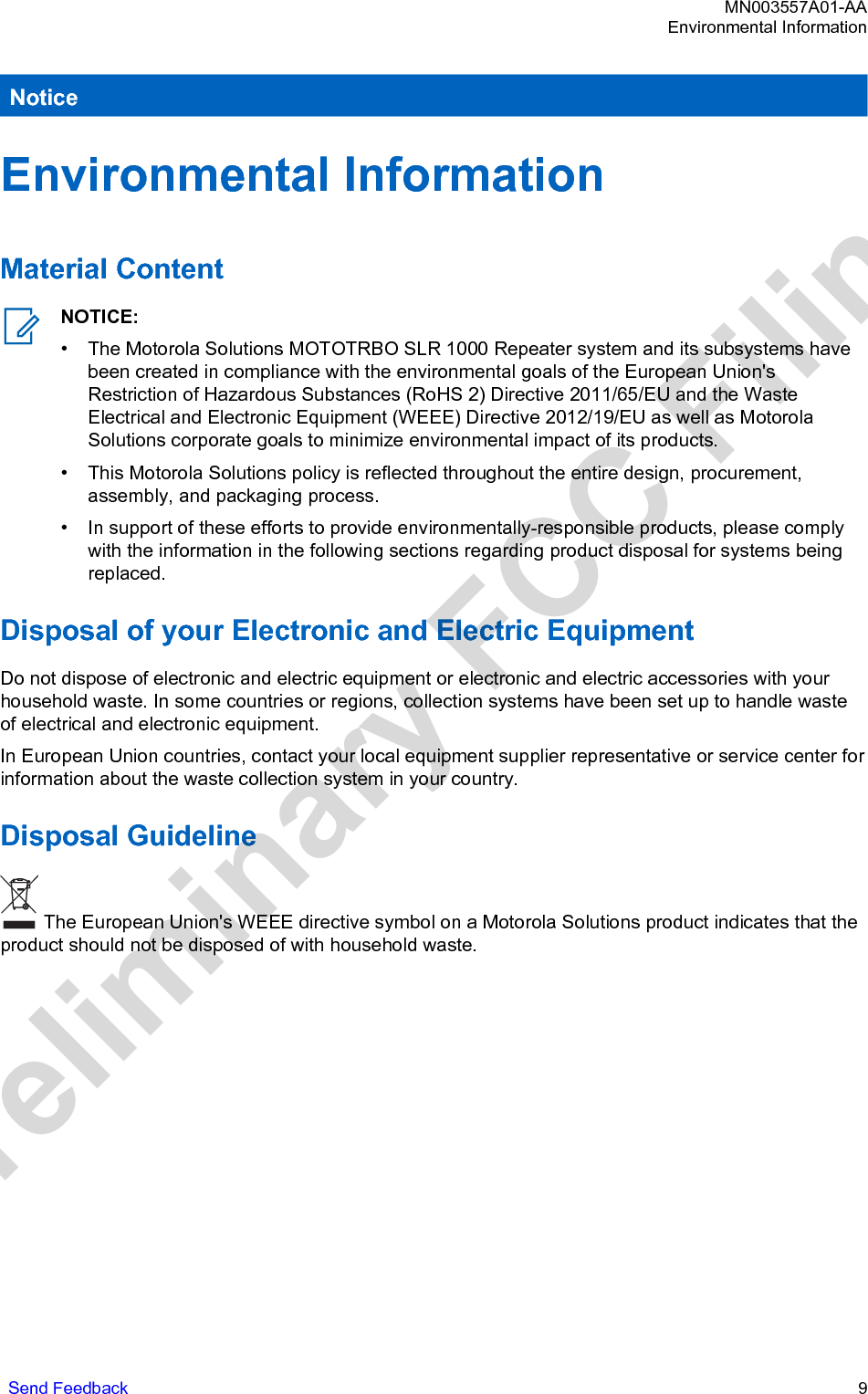
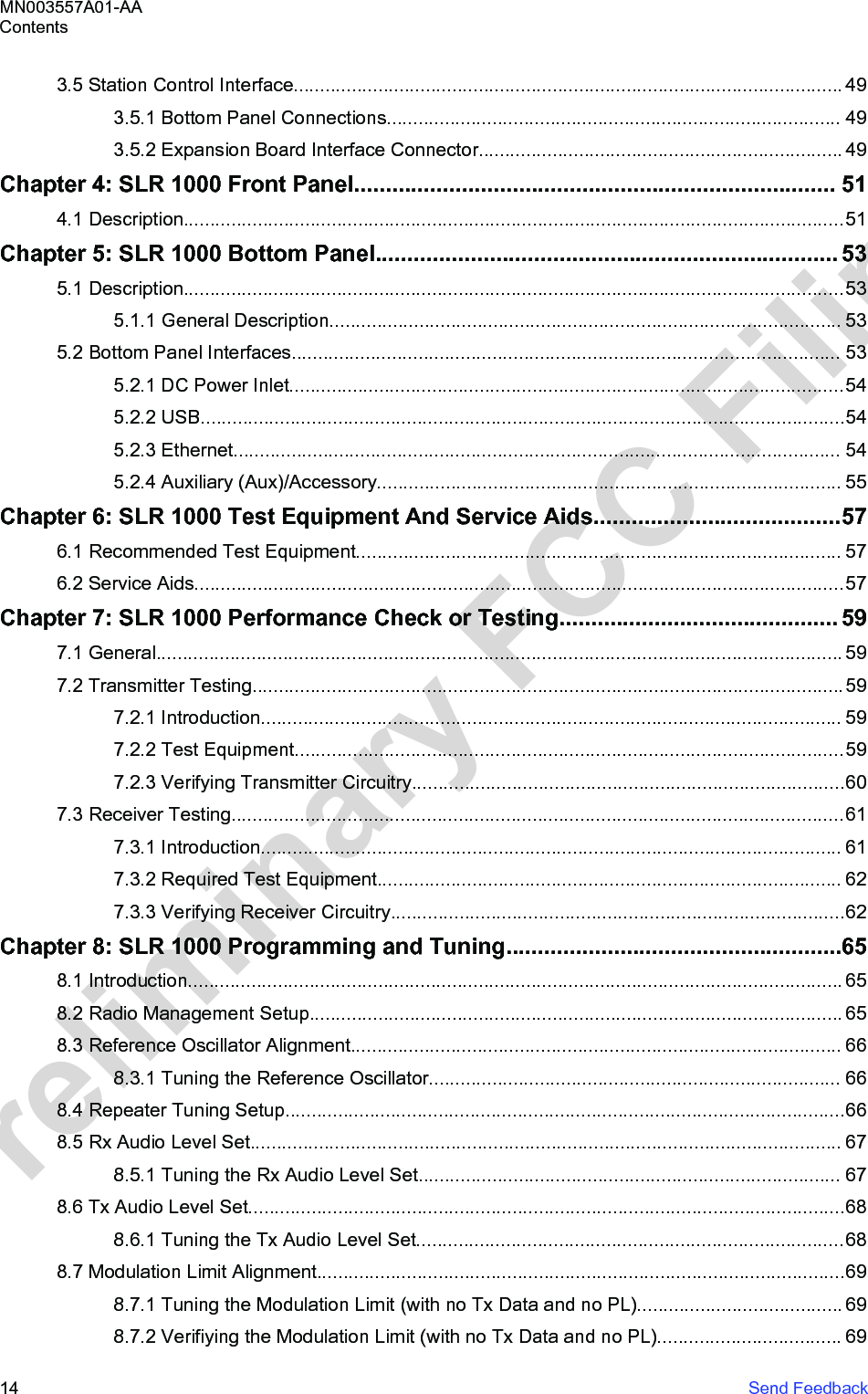
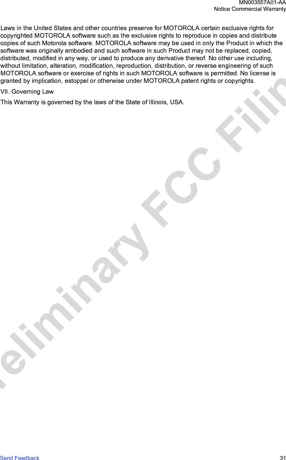
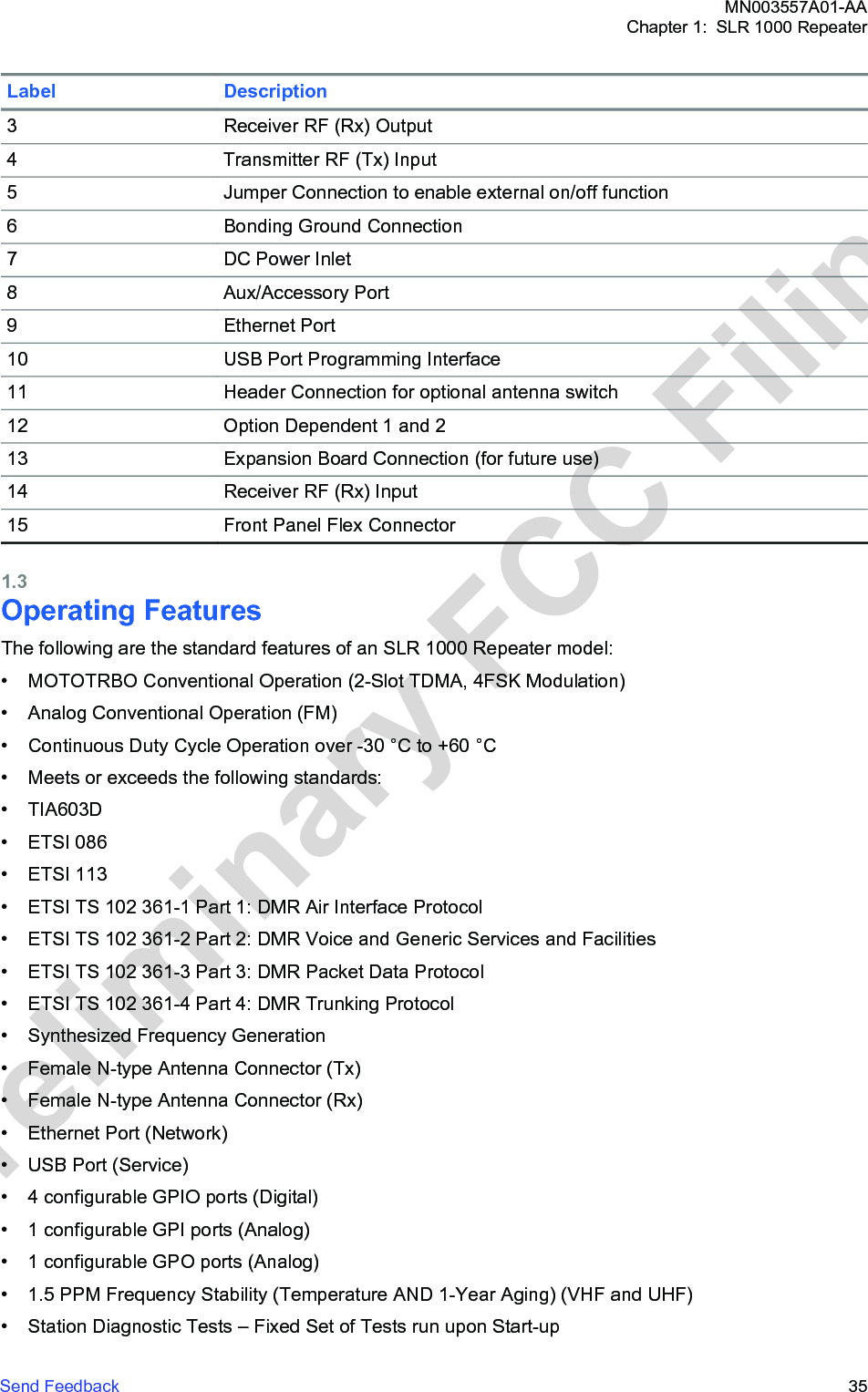
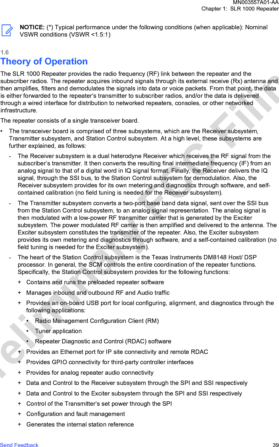
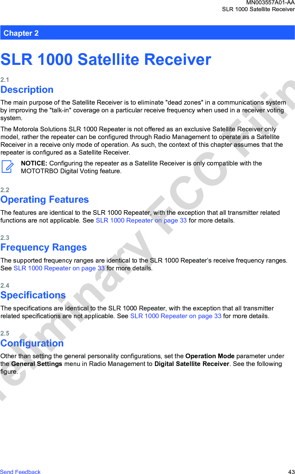
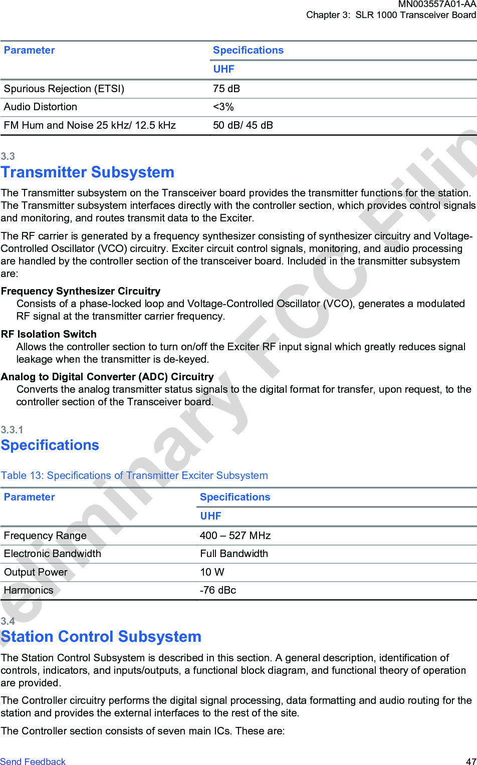
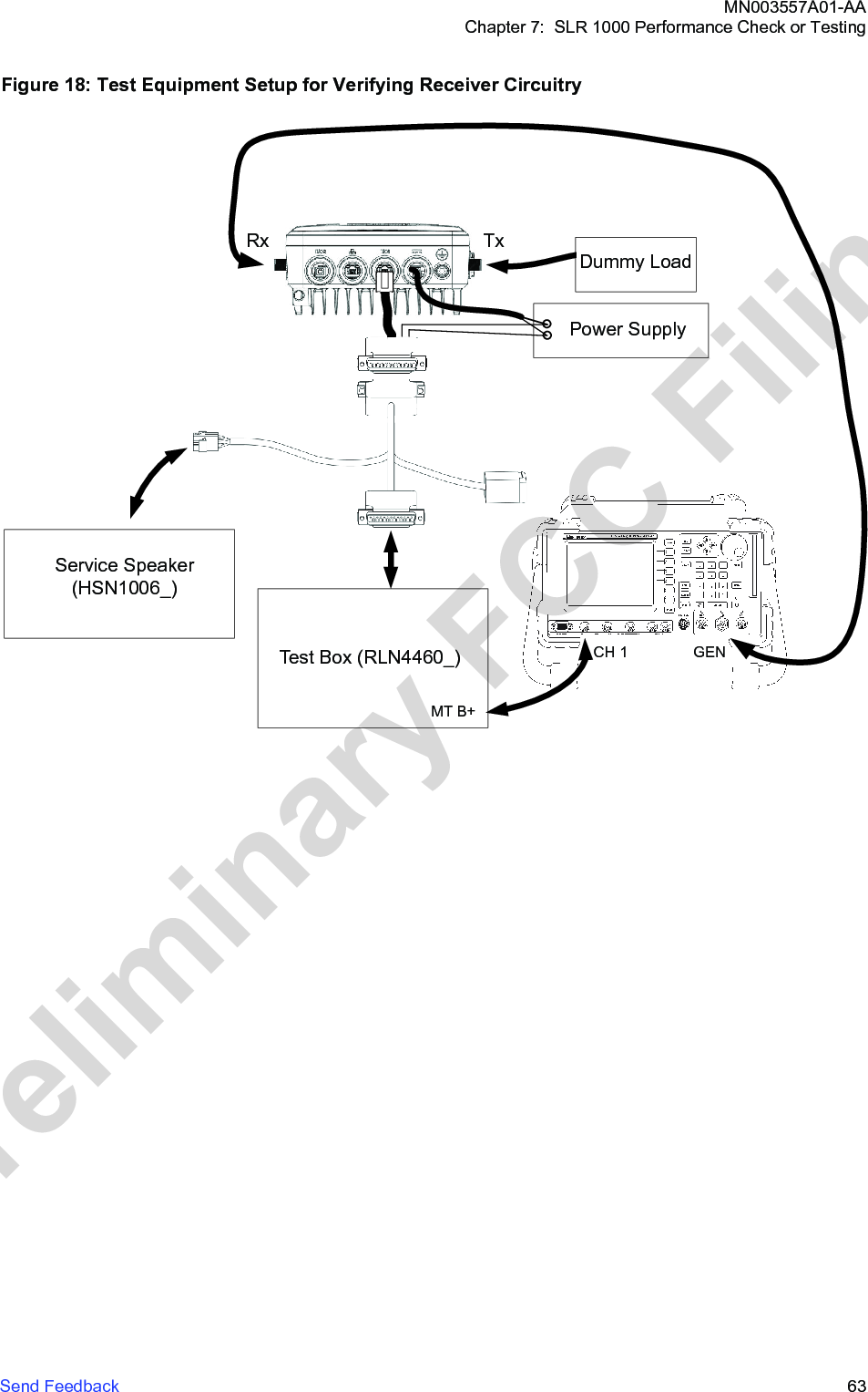
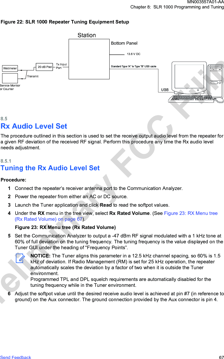
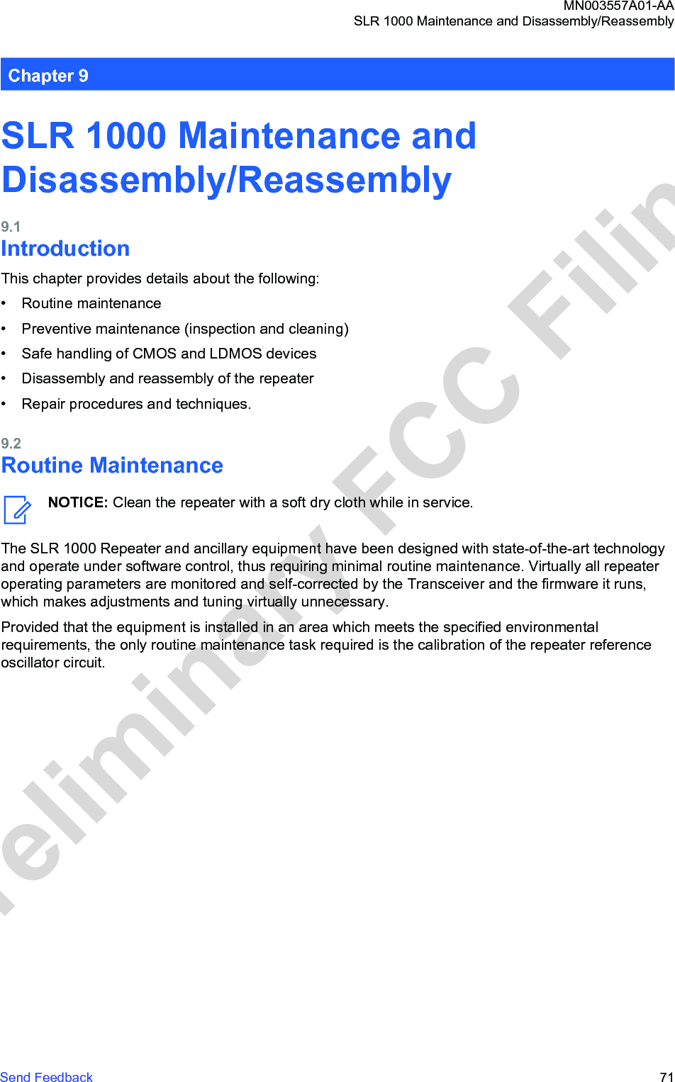
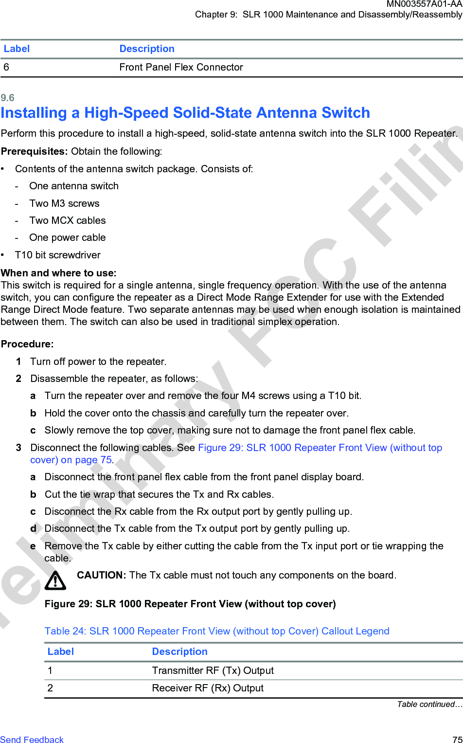
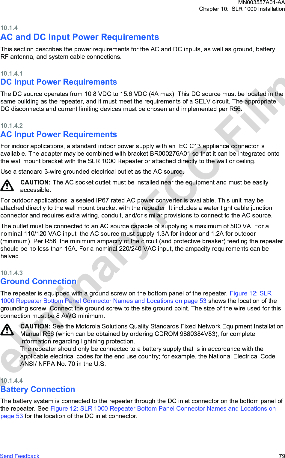
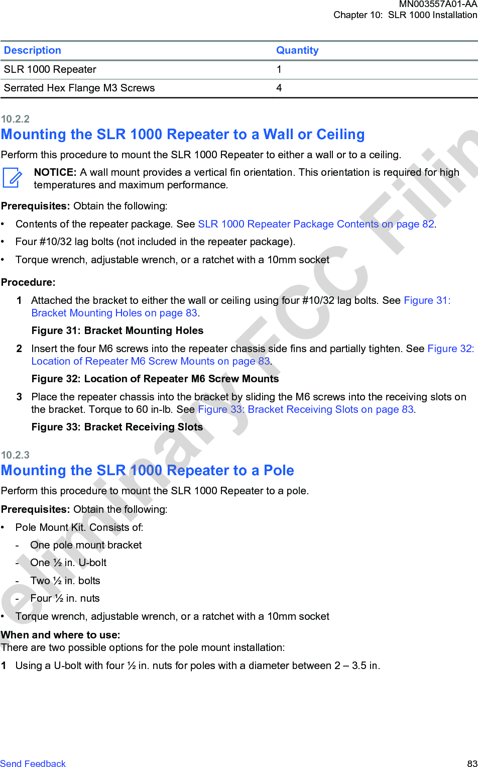
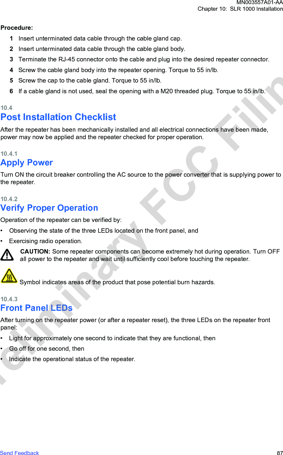
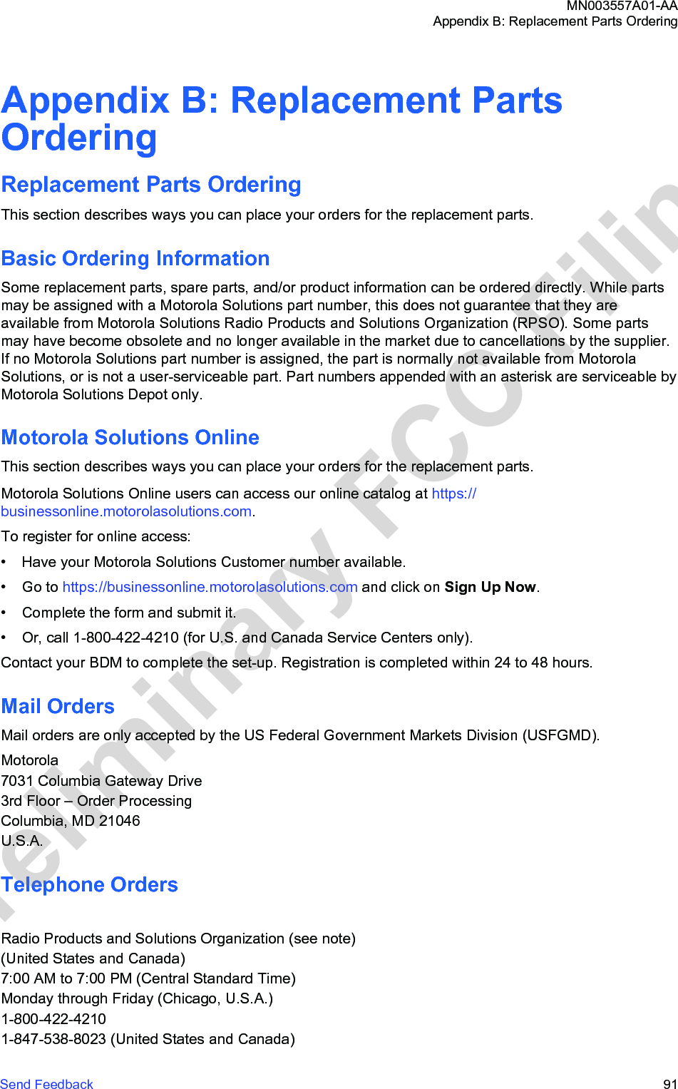
![Outdoor Exposure Prediction ModelThis section describes how to determine the outdoor exposure model prediction of an antenna.Whole-Body SAR ComplianceFull-wave and half-wave simulations are represented to show the exposure conditions.The full-wave simulations based on the FDTD method were performed at 400 MHz and 470 MHz whichincludes the operating band of the evaluated antenna. The simulation code employed was XFDTD,version 7.3 by Remcom Inc., State College, PA. The exposed subject was modeled by aheterogeneous full body model standardized for SAR evaluation according to the IEC/IEEE 62704-2draft standard [12].The half-wave dipole antenna and maximum radiated power were used to represent the exposurecondition. At each frequency, two individual simulations representing the exposure from the front andback at 40 cm distance from the dipole were conducted. No losses other than dissipation of RF energyinside the human body were assumed in the FDTD modeling, which provides an extra degree ofoverestimation.Figure 42: H-Field and SAR Distributions for Exposure from a Dipole AntennaTable 30: Whole-Body Average SAR Results on page 100 presents the whole-body average SARresults for the simulated conditions at. To account for the actual measured antenna gain of 4.1 dBiwhich is higher than the half -wave dipole gain by factor of 1.57 the whole-body average results werescaled by that factor and are present in a separate column as adjusted whole-body SAR valuesalongside.Table 30: Whole-Body Average SAR ResultsTable Num-berFrequency MHz Antenna Posi-tionWhole-BodySAR W/kgAdjustedWhole-BodySAR, W/kg1 400 Front 0.010 0.016Table continued…MN003557A01-AAAppendix E: MOTOTRBO Repeater EME Assessment100 Send FeedbackPreliminary FCC Filing](https://usermanual.wiki/Motorola-Solutions/99FT4100/User-Guide-3392771-Page-100.png)
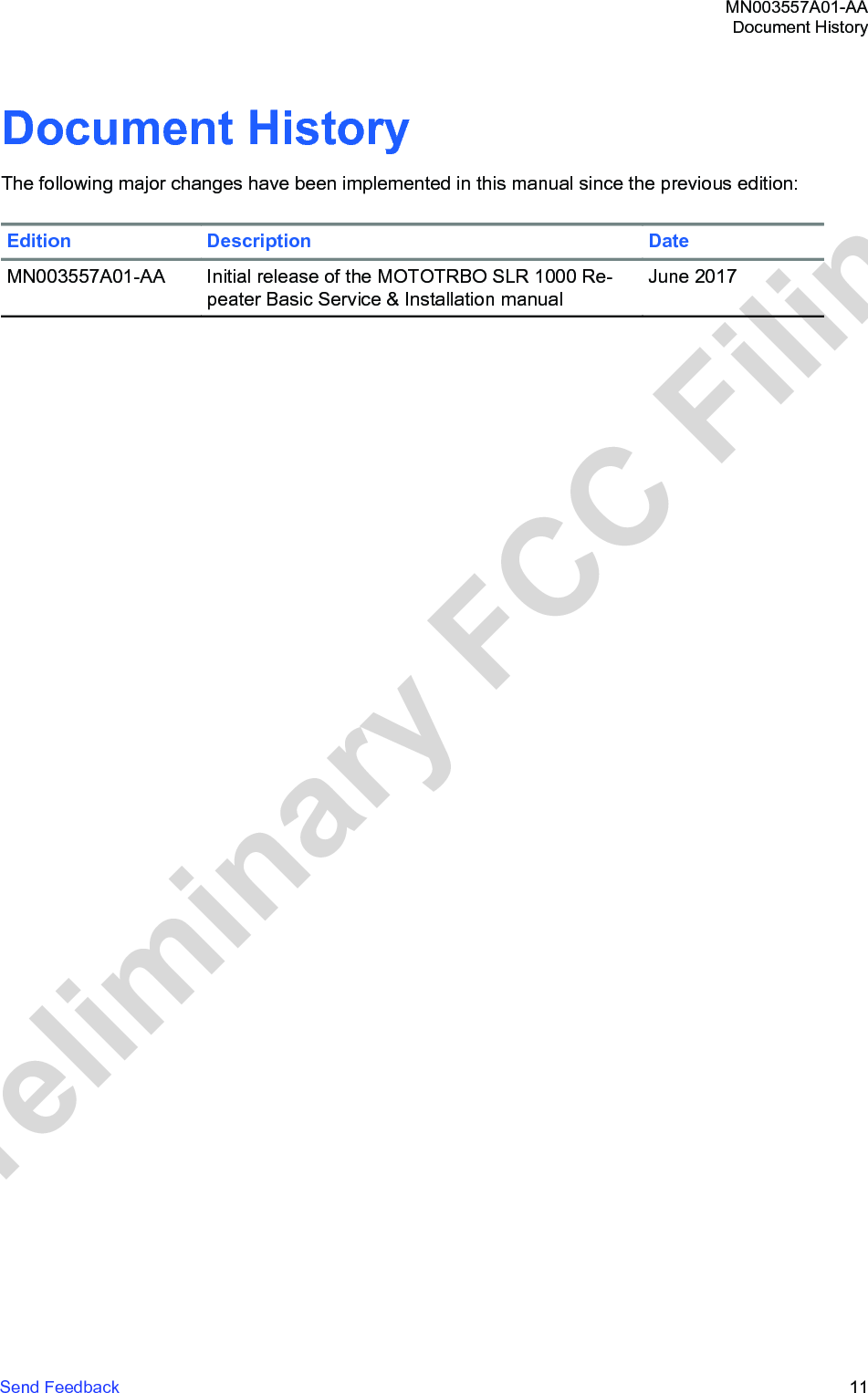
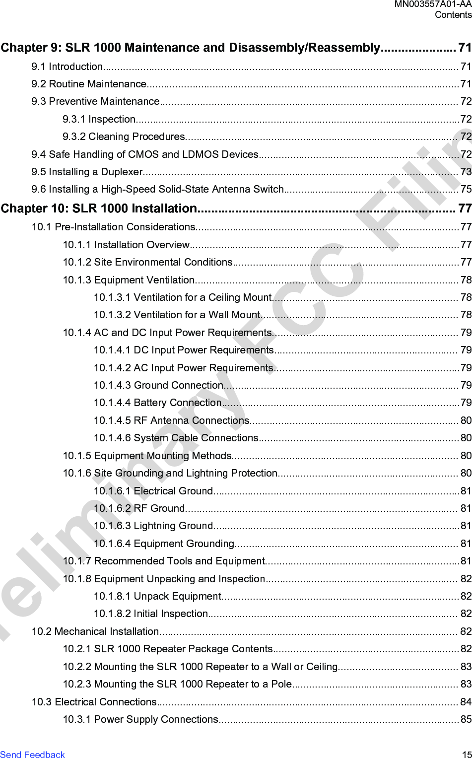
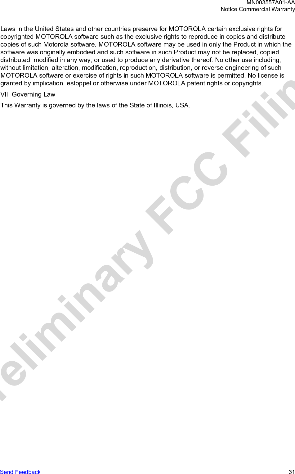
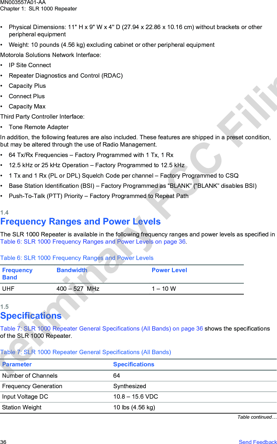
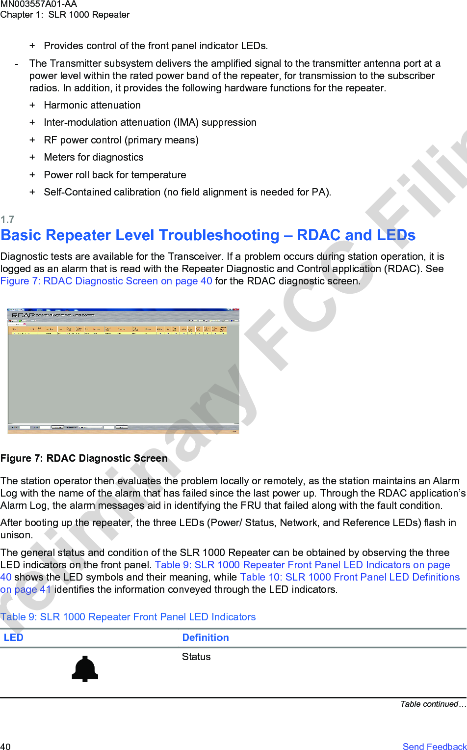
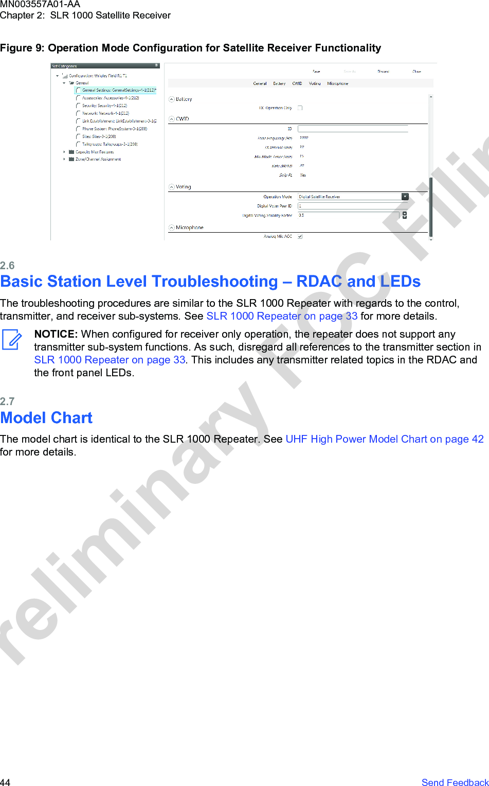
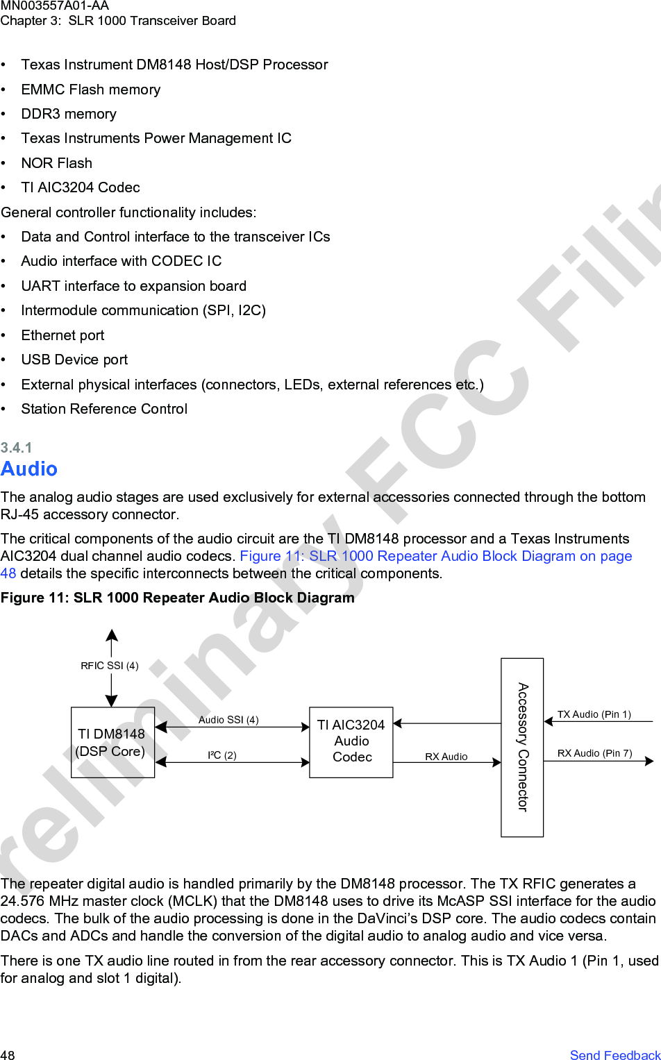
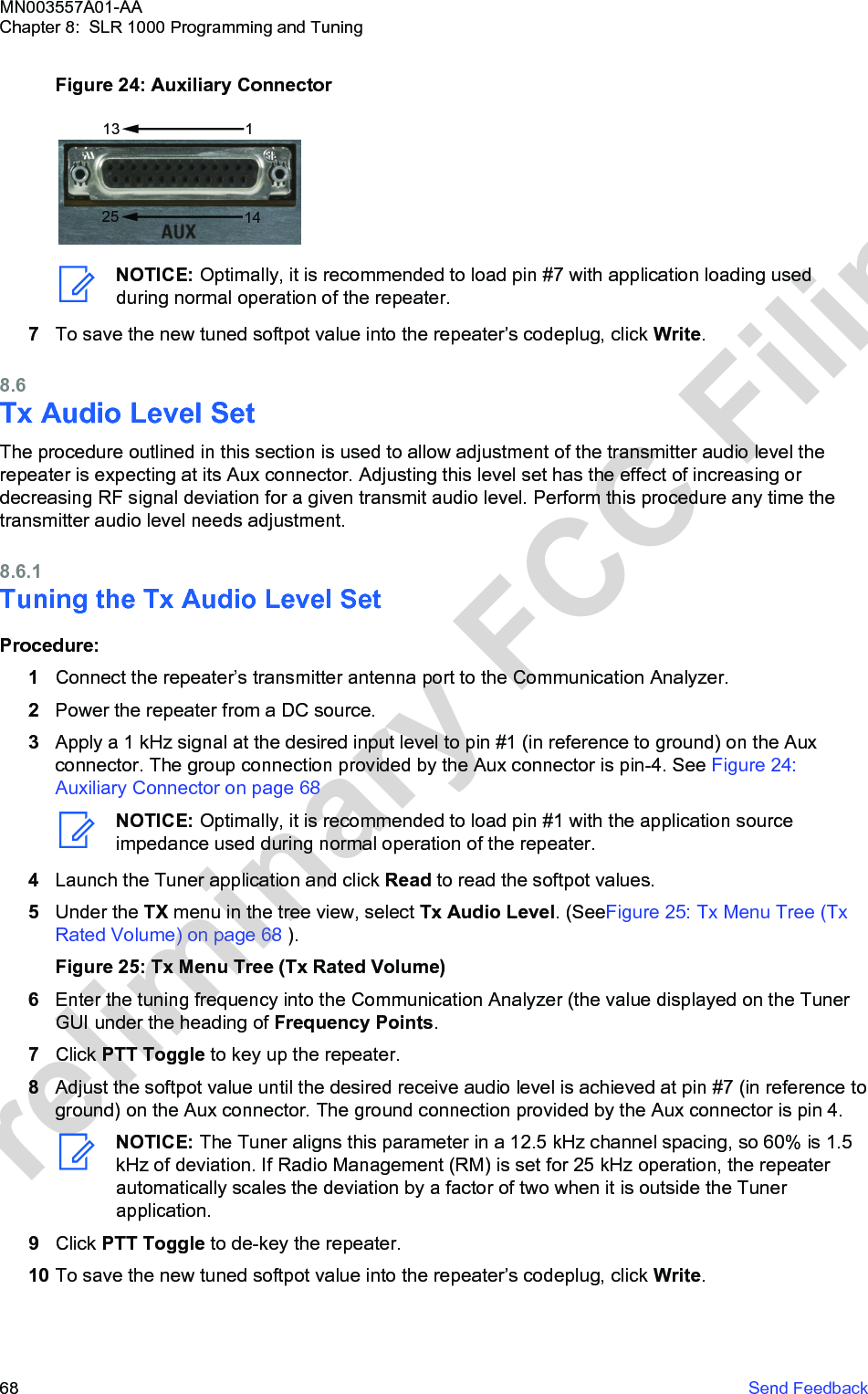
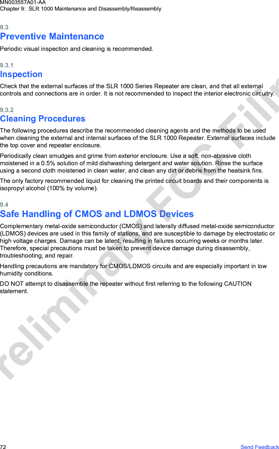
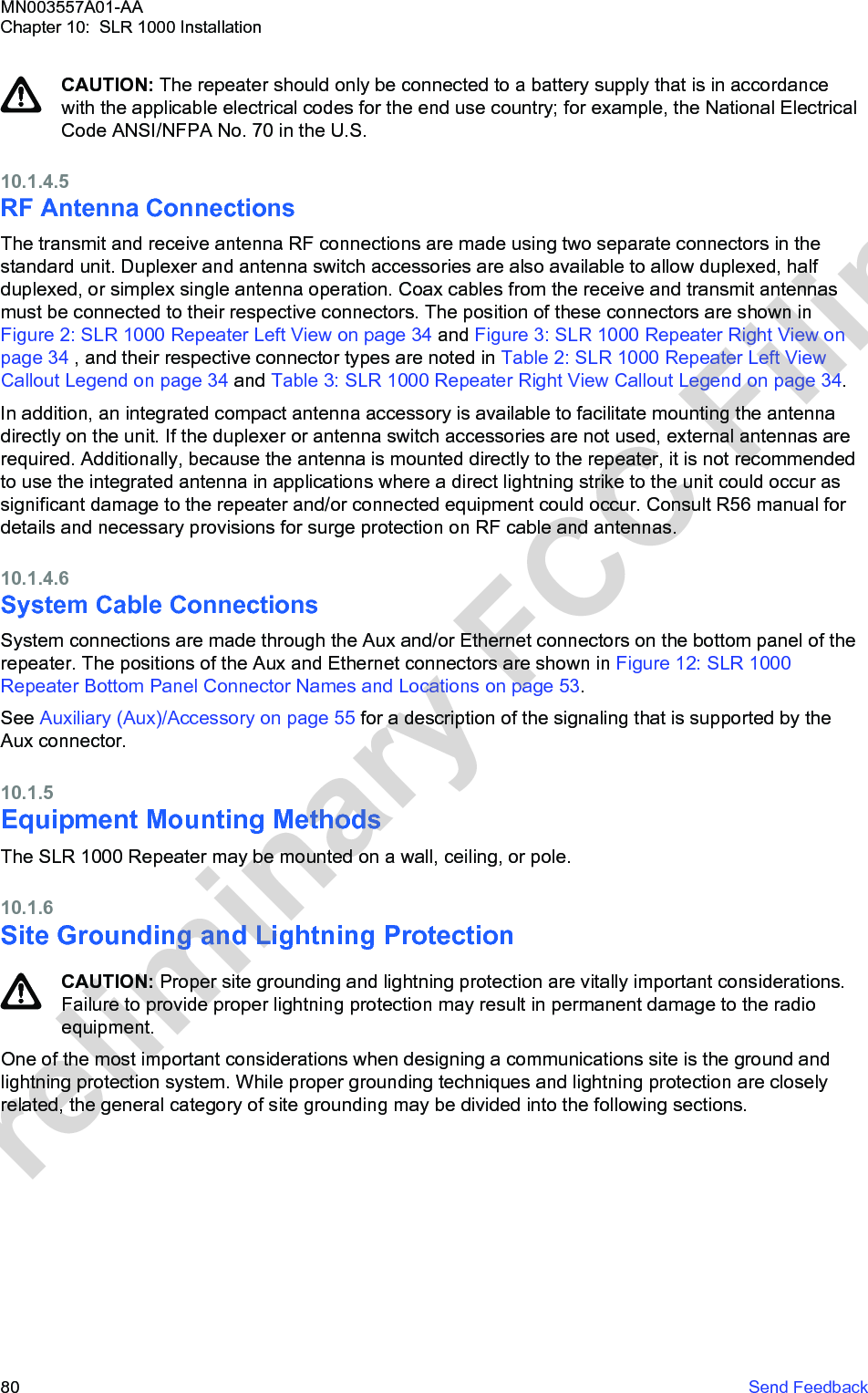
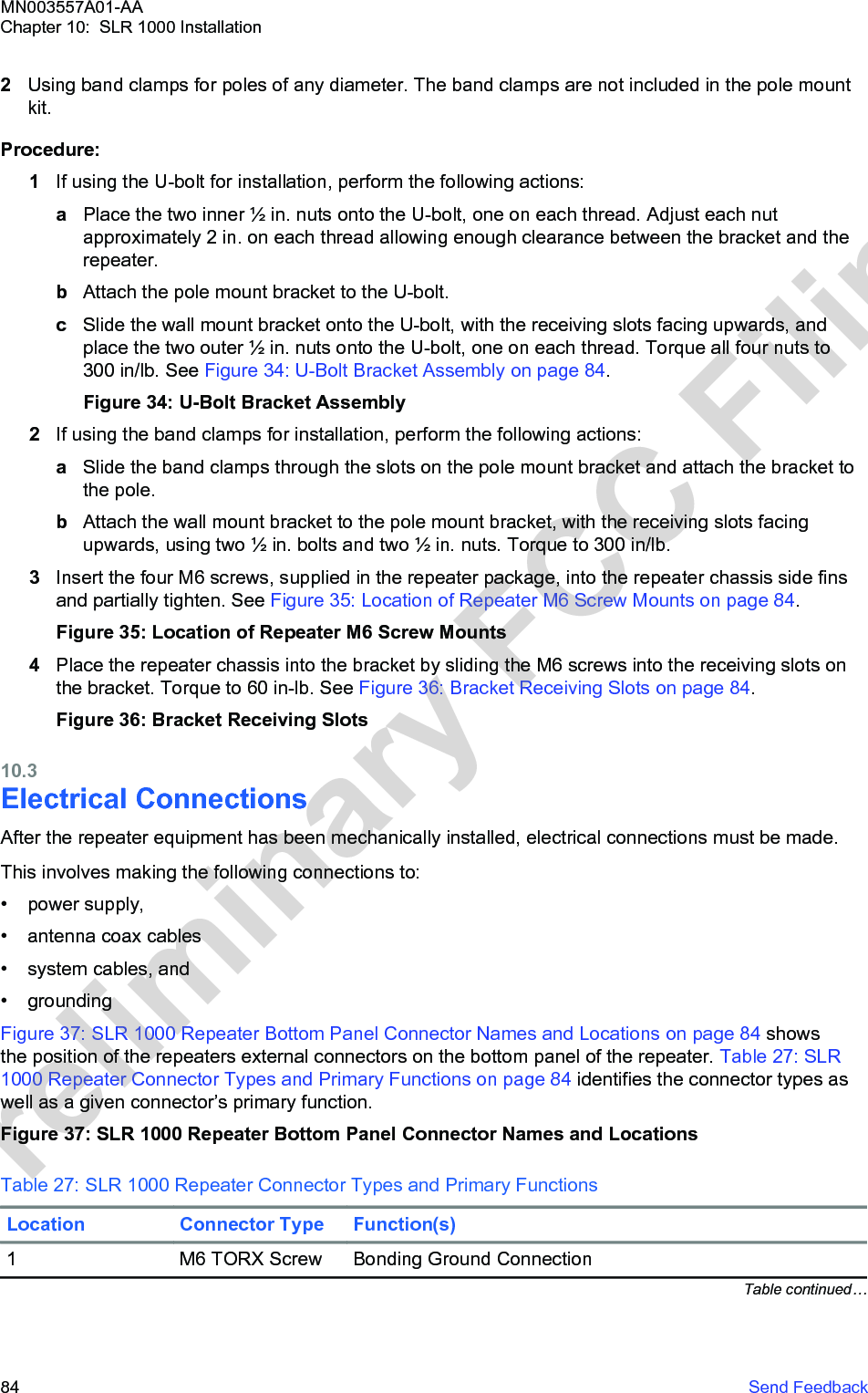
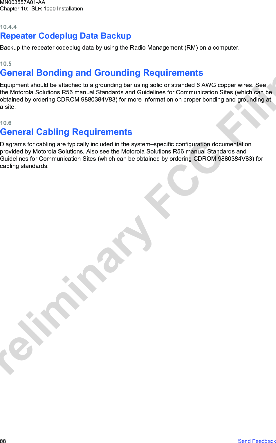
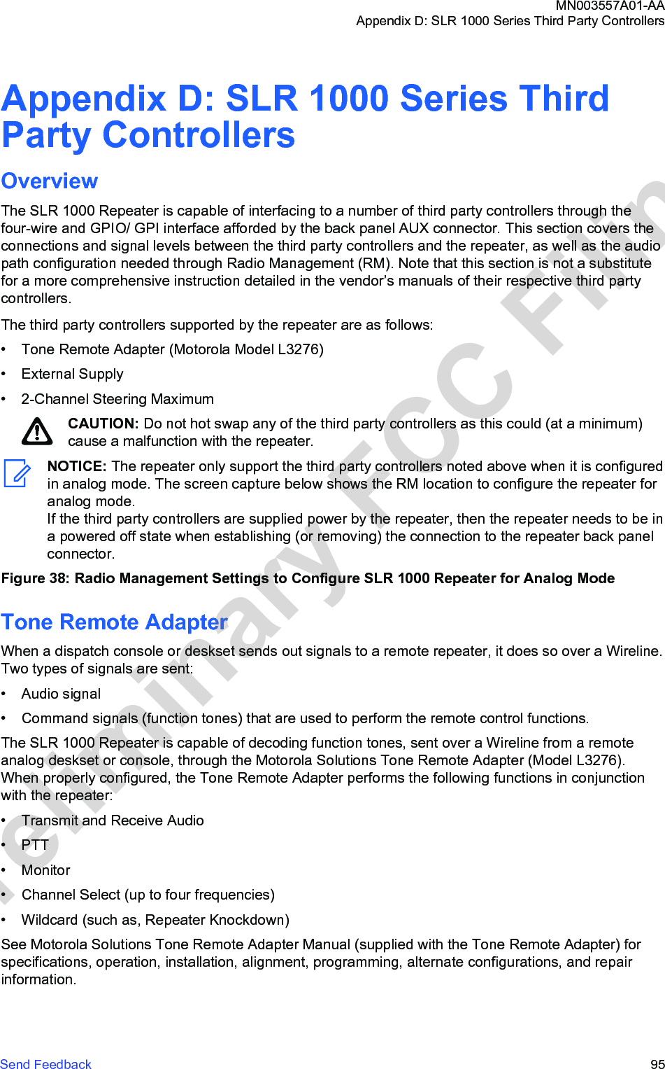
![Table Num-berFrequency MHz Antenna Posi-tionWhole-BodySAR W/kgAdjustedWhole-BodySAR, W/kg2 400 Back 0.012 0.0195 470 Front 0.010 0.0166 470 Back 0.012 0.019The highest adjusted whole-body average SAR value from these simulations is 0.019 W/kg. This valueis below the US FCC whole-body SAR limits for both controlled (occupational) and general publicexposure environments, 0.4 W/kg and 0.08 W/kg, respectively.Peak 1-g Average SAR ComplianceThe maximum measured gain of the antenna is used in this assessment to produce the conservativeevaluation of exposure in the operating condition of the radio.The compliance relative to the US FCC limits for the peak 1-g average SAR [11] is evaluated at p=40cm from the antenna by estimating an upper bound for said quantity. Evaluation of the peak powerdensity at 40 cm distance is performed based on maxim radiated power P =10 W and maximumantenna gain Gant = 4.1 dBi:Making the further conservative assumption that, at the point of maximum exposure, the wholeimpinging power over a cross-section equal to one face of a 1-g cube of tissue (an area equal to 1cm2assuming that the tissue density is 1g/cm3) is absorbed by the body inside that cube, the followingupper bound for the peak 1-g average SAR is derived.This value is below the US FCC peak 1-g average SAR limits [11] for both controlled (occupational)and uncontrolled (general public) environments, 8 W/kg and 1.6 W/kg, respectively.MN003557A01-AAAppendix E: MOTOTRBO Repeater EME AssessmentSend Feedback 101Preliminary FCC Filing](https://usermanual.wiki/Motorola-Solutions/99FT4100/User-Guide-3392771-Page-101.png)
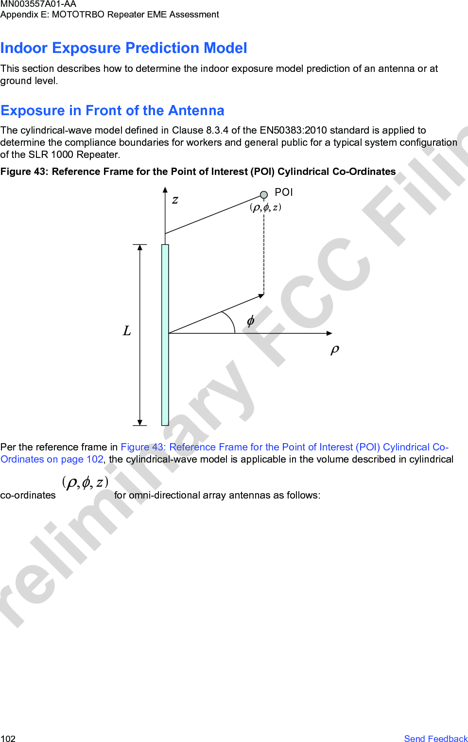
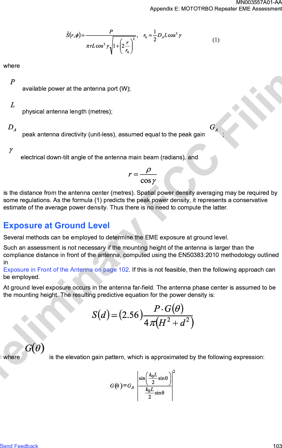
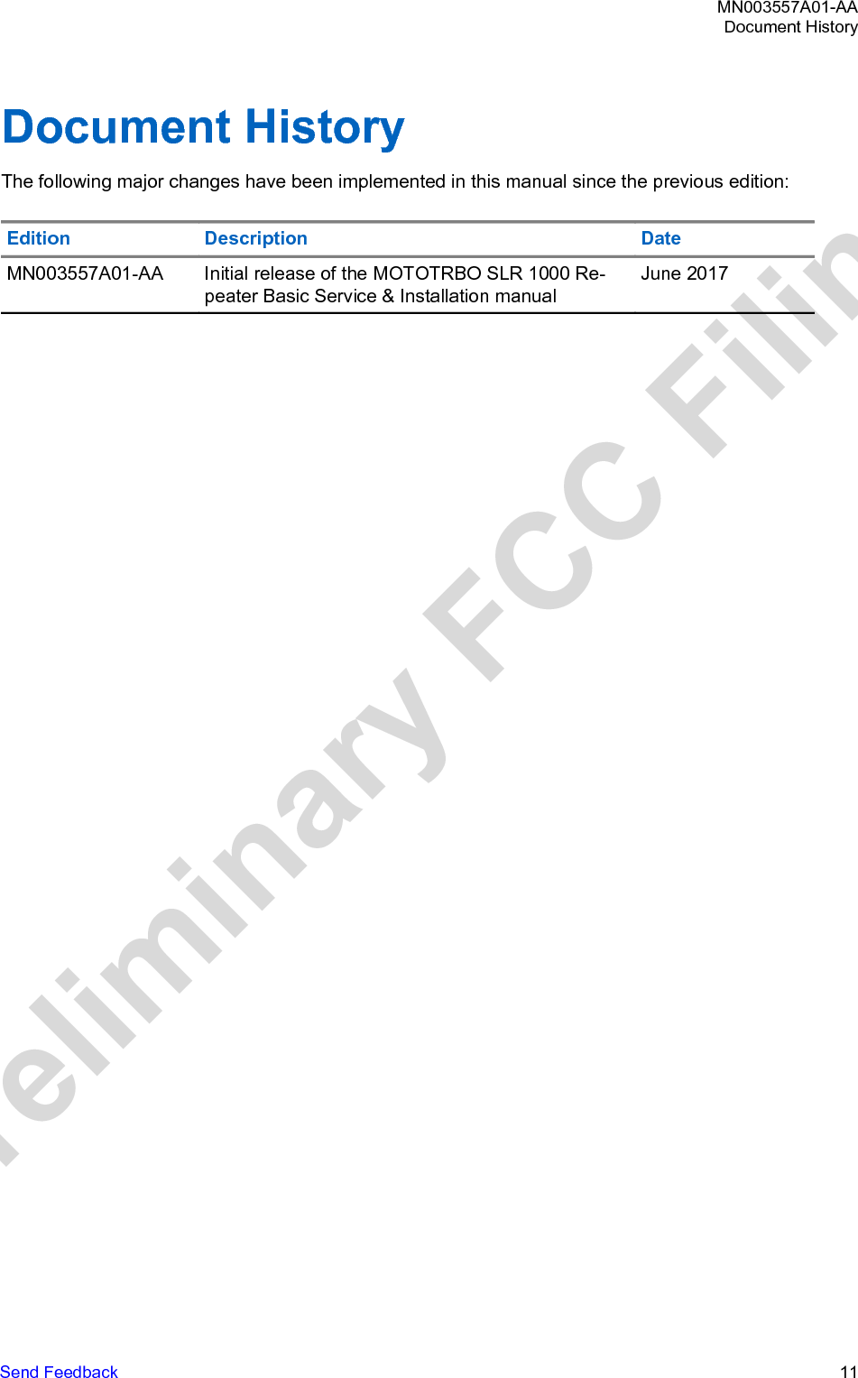
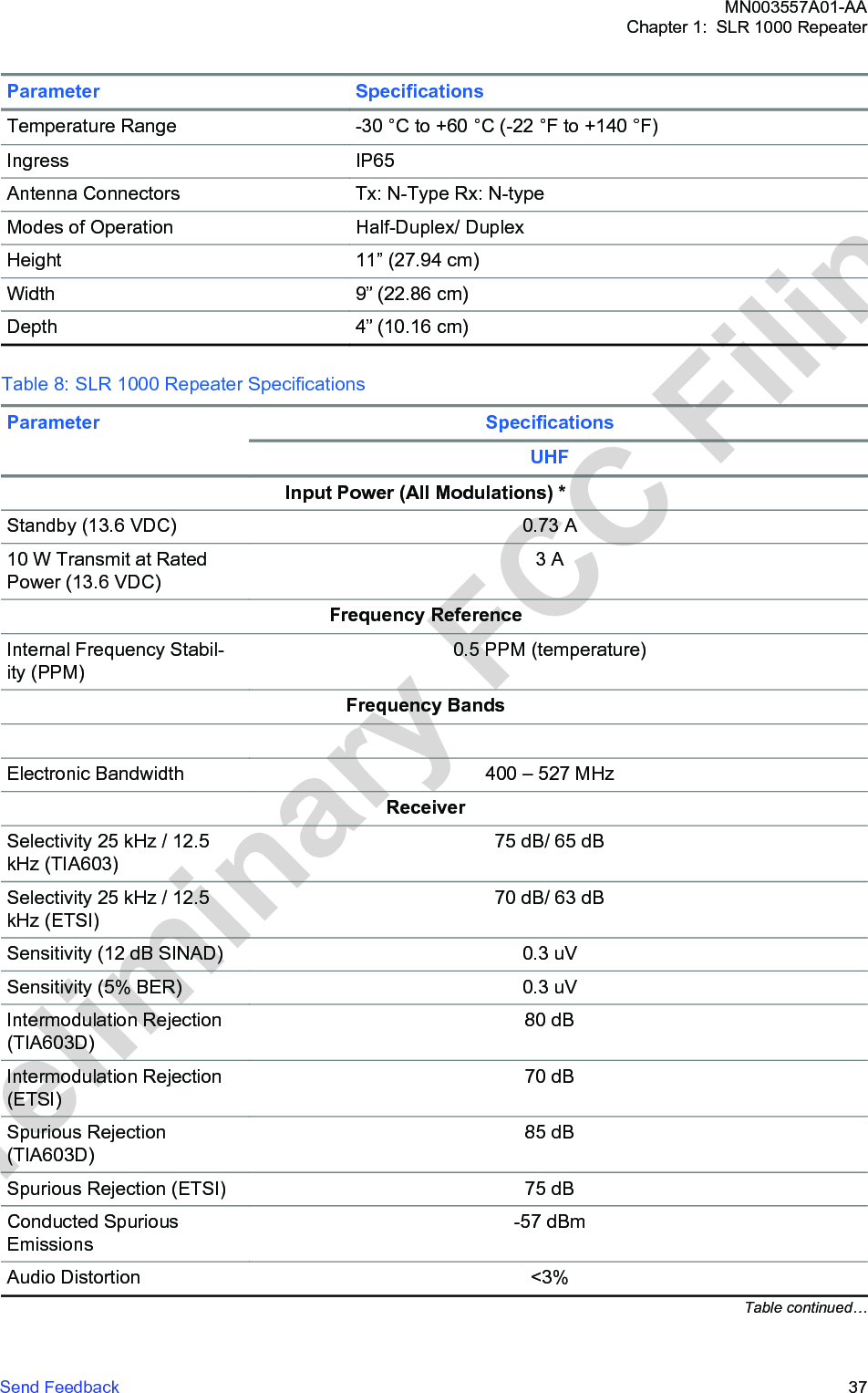
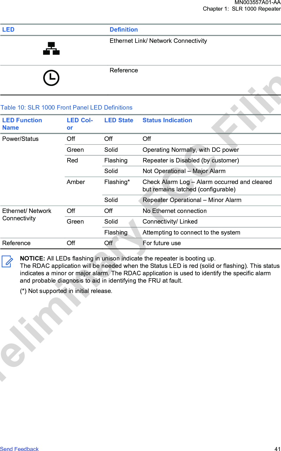
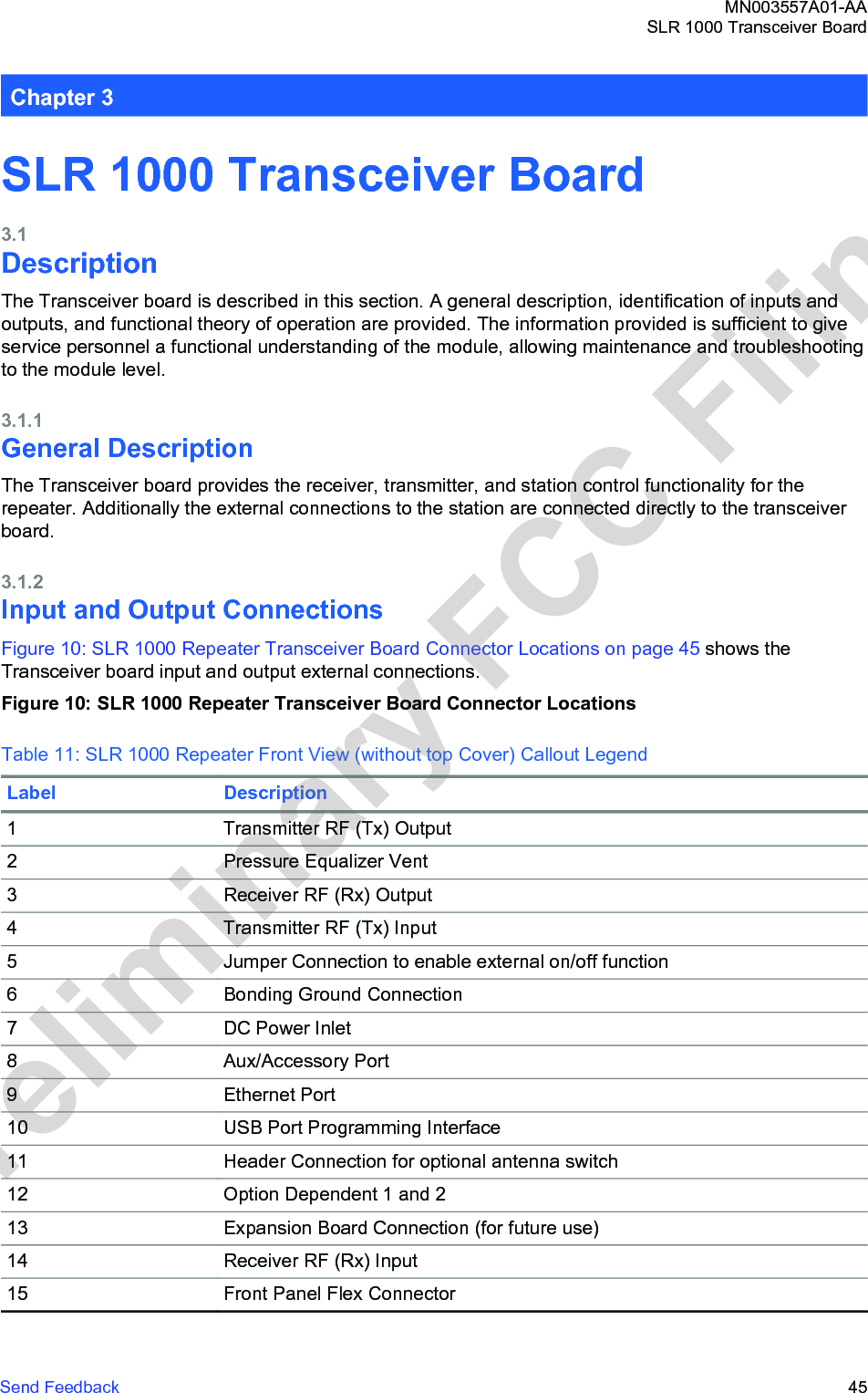
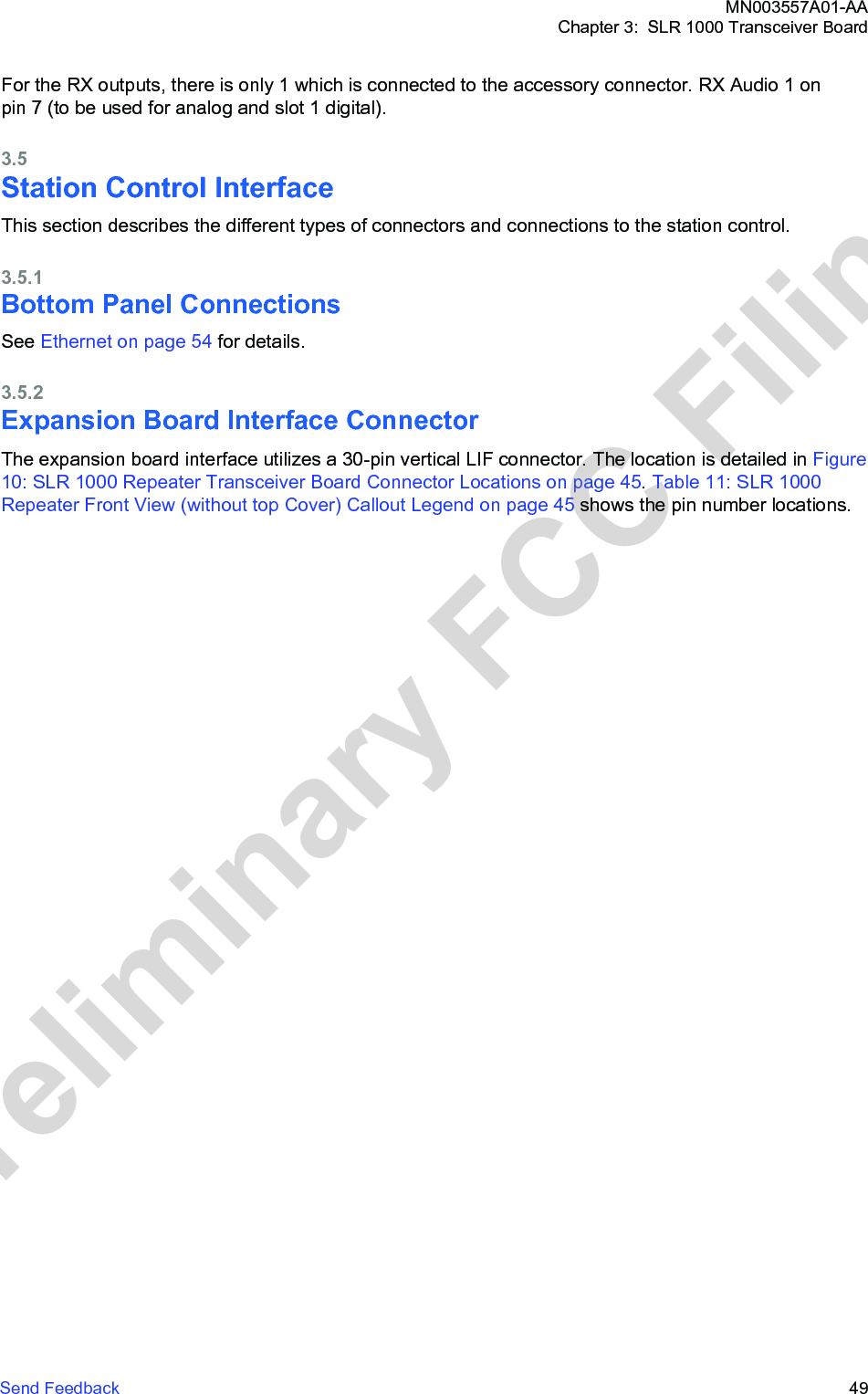
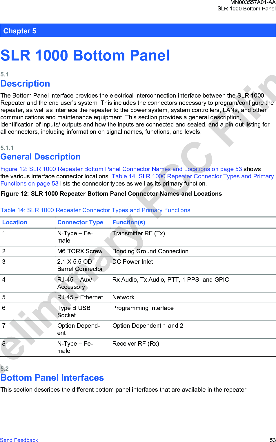
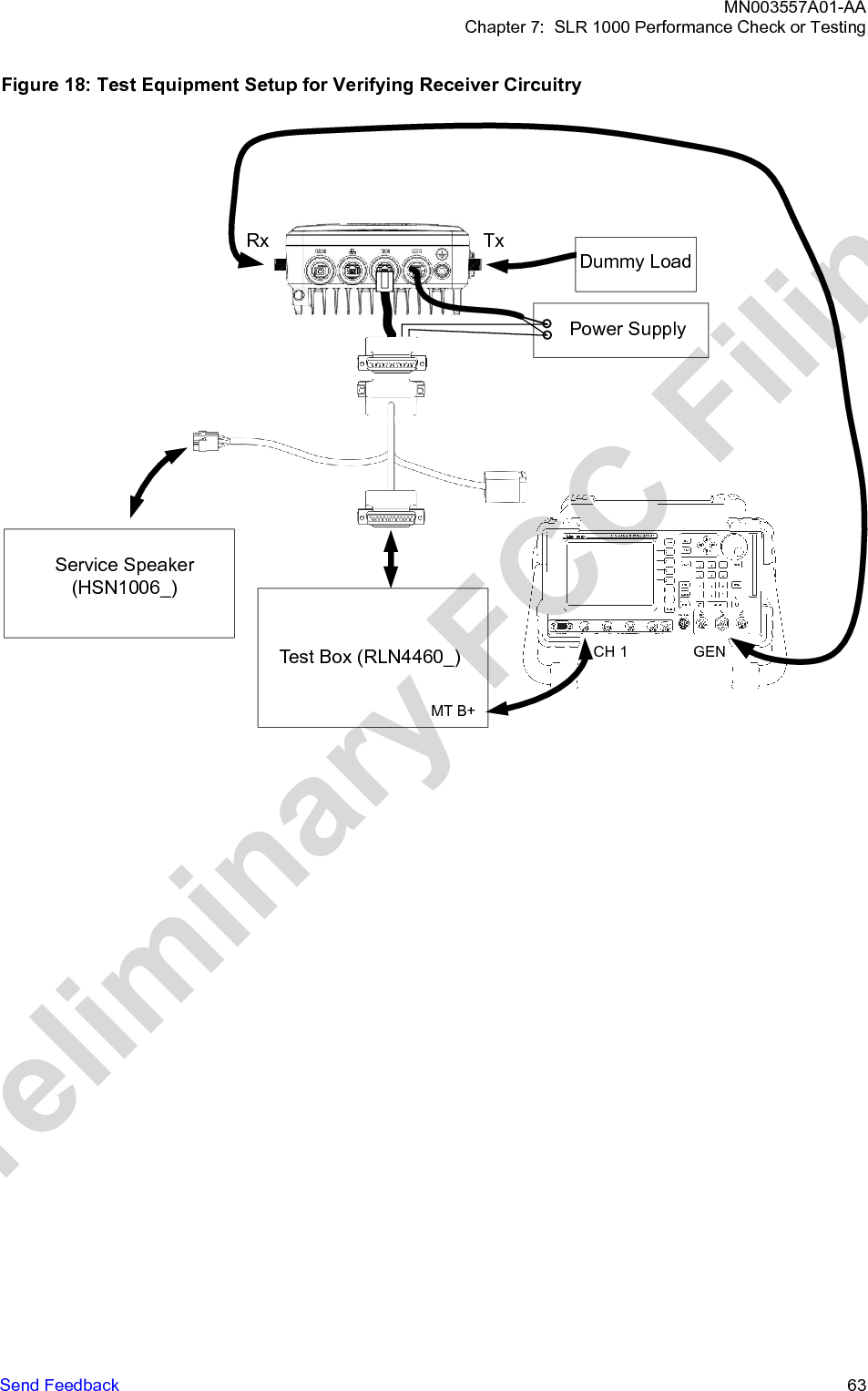
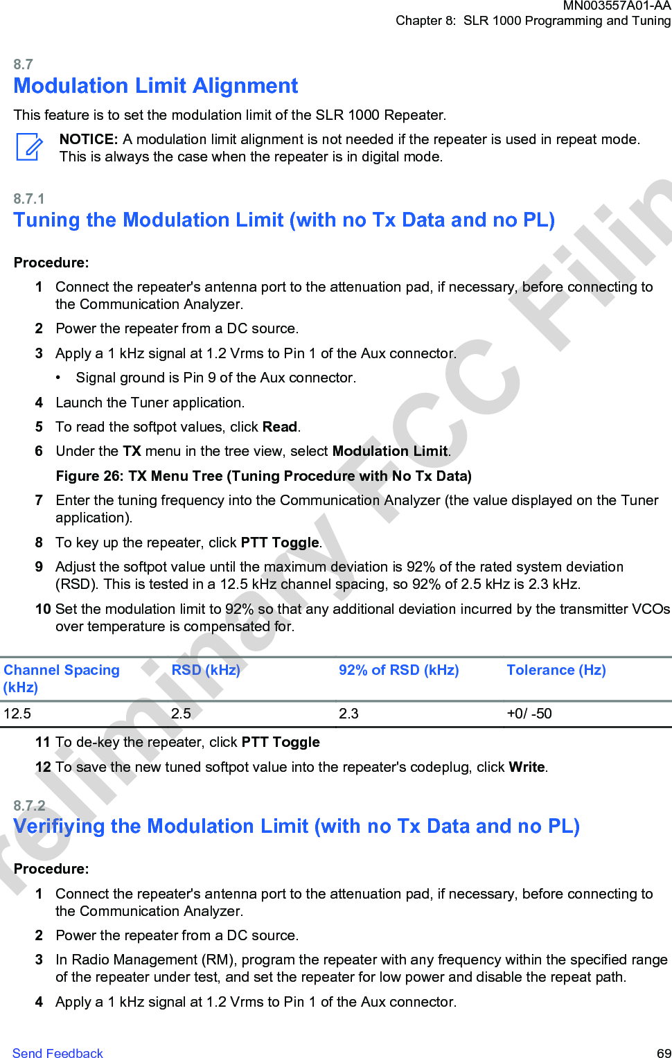
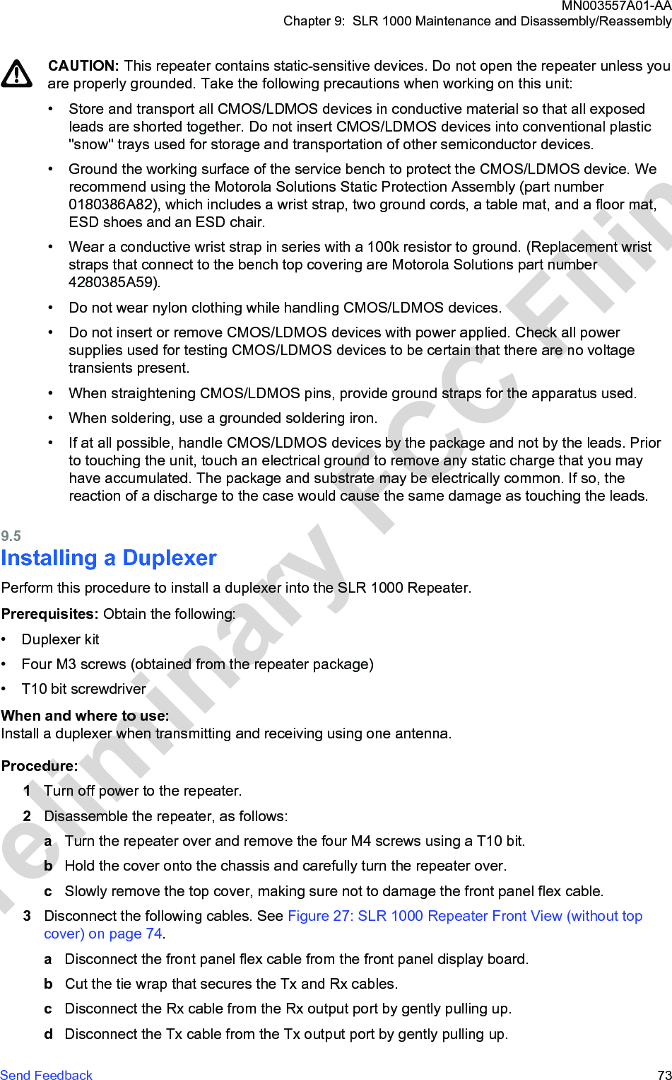
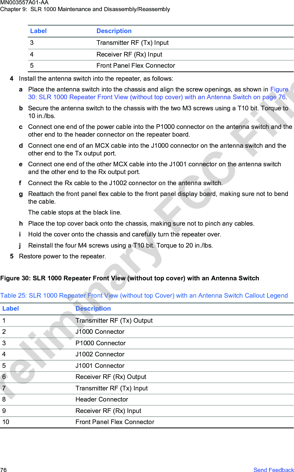
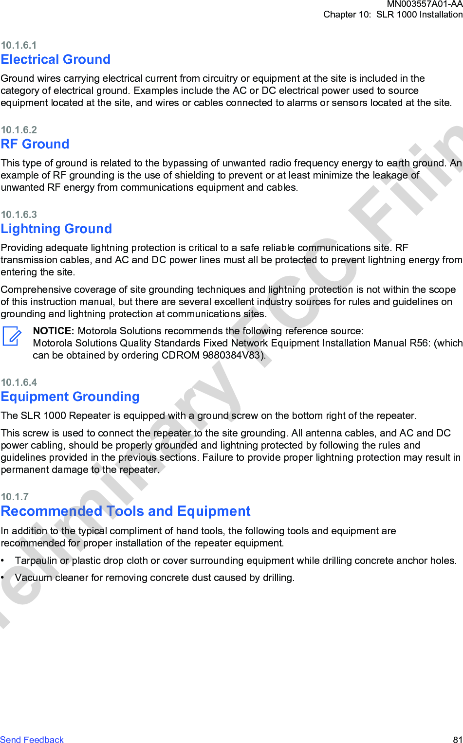
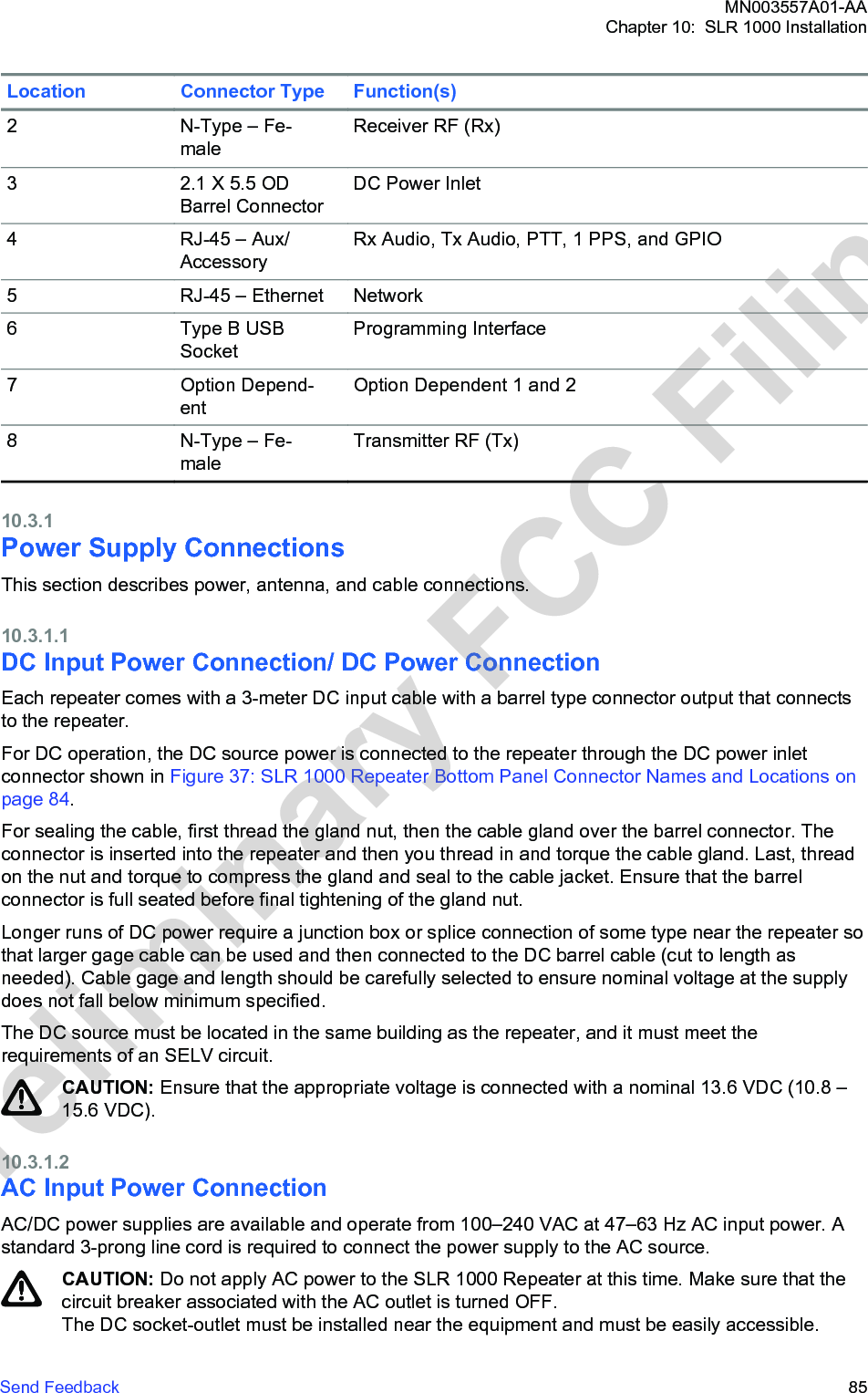
![where is the free-space wavenumber and L is the effective antenna length yieldingthe appropriate vertical beamwidth, while H is the antenna height above ground and d is the point ofinterest (POI) distance from the vertical antenna projection to ground (see the following figure). Themultiplicative factor 2.56 is introduced to enforce near-perfect, in-phase ground reflection asrecommended in [2]. In this case, spatial averaging is not carried out to make the EME exposureassessment more conservative.Figure 44: Schematic of the Ground-Level Exposure Model Adopted for the AssessmentTypical System ConfigurationThe SLR 1000 Repeater operates in different frequency ranges with different channels transmitting 10W radio frequency (RF) power.The typical system configuration comprises an omnidirectional array antenna featuring 6–10 dBd gain,installed at or above 20 m from ground level, and fed by the repeater through a combiner characterizedby a typical 3 dB transmission loss, and a 30 m 7/8" coaxial cable characterized by a typical 2.7 dB/100m loss, resulting in a total 3.9 dB transmission loss. Based on these characteristics, the RF powerat the antenna input is about 20 W.Since shorter antennas provide a conservative EME exposure assessment from equation (1), when, the parameters of a typical 6.6 dBd antennas are employed (it has to be verified that theresulting compliance distances are indeed smaller than ). Such an antenna (such as, AndrewDB408) would exhibit a typical elevation beamwidth of about 14 degrees.Exposure LimitsGuidelines are used for the EME exposure assessment.Based on the operating frequency range, the most conservative power density limits are those definedin the ICNIRP guidelines [1]. The guidelines are 10.1 W/m2 for occupational exposure, and 2.02 W/m2for general public exposure.MN003557A01-AAAppendix E: MOTOTRBO Repeater EME Assessment104 Send FeedbackPreliminary FCC Filing](https://usermanual.wiki/Motorola-Solutions/99FT4100/User-Guide-3392771-Page-104.png)
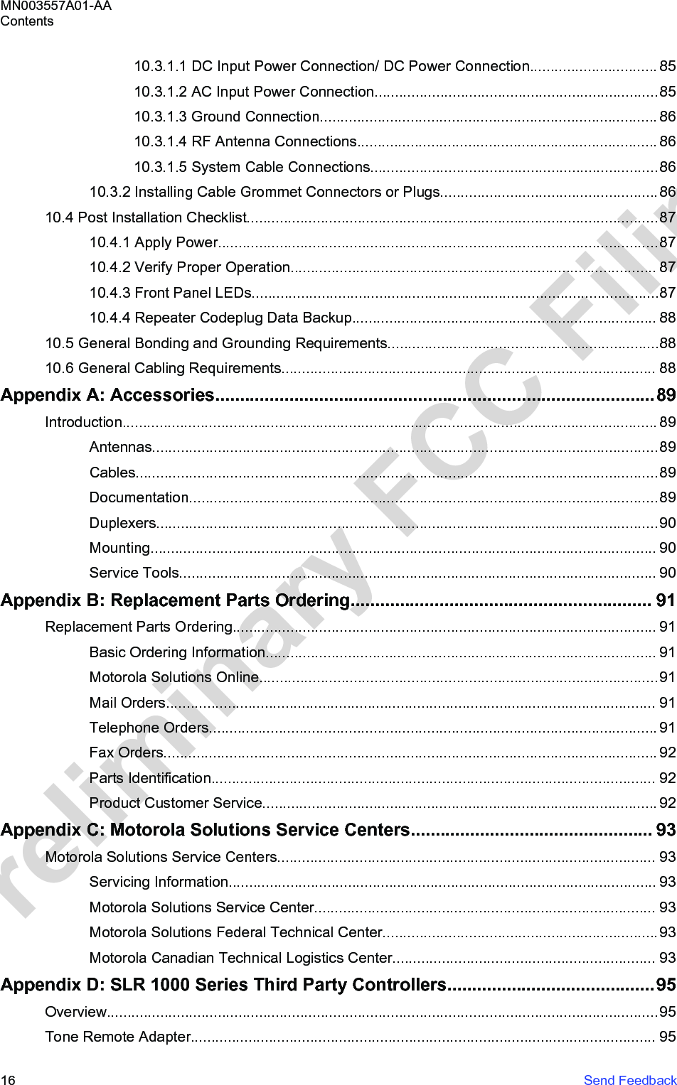
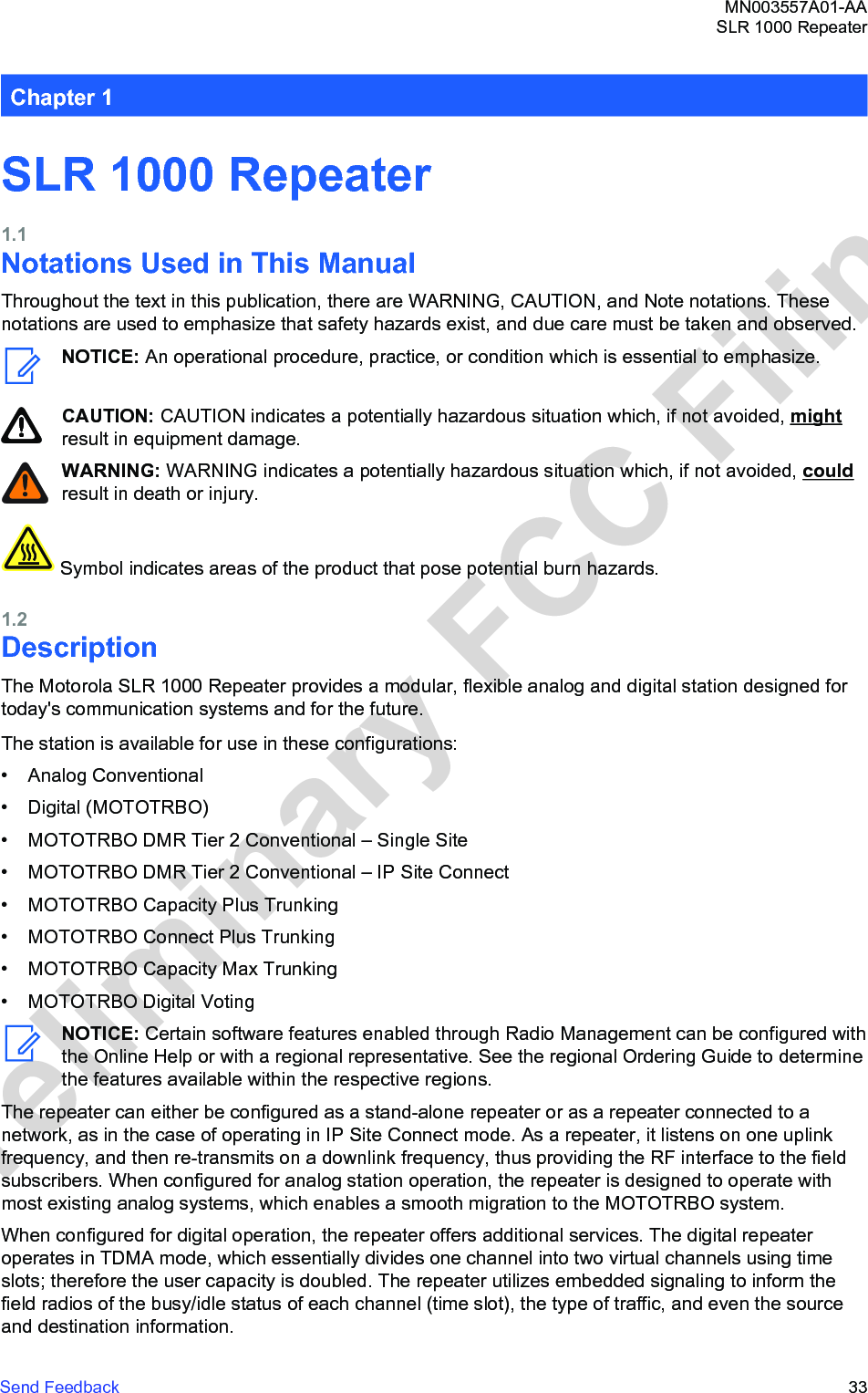
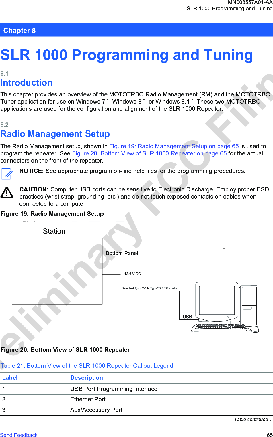
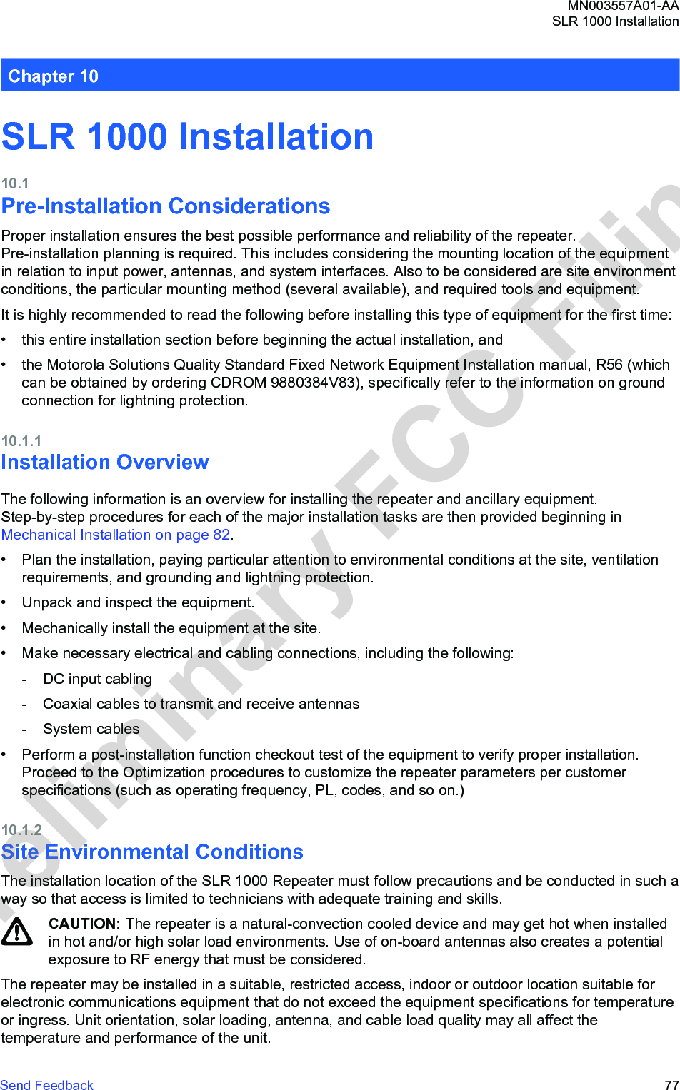
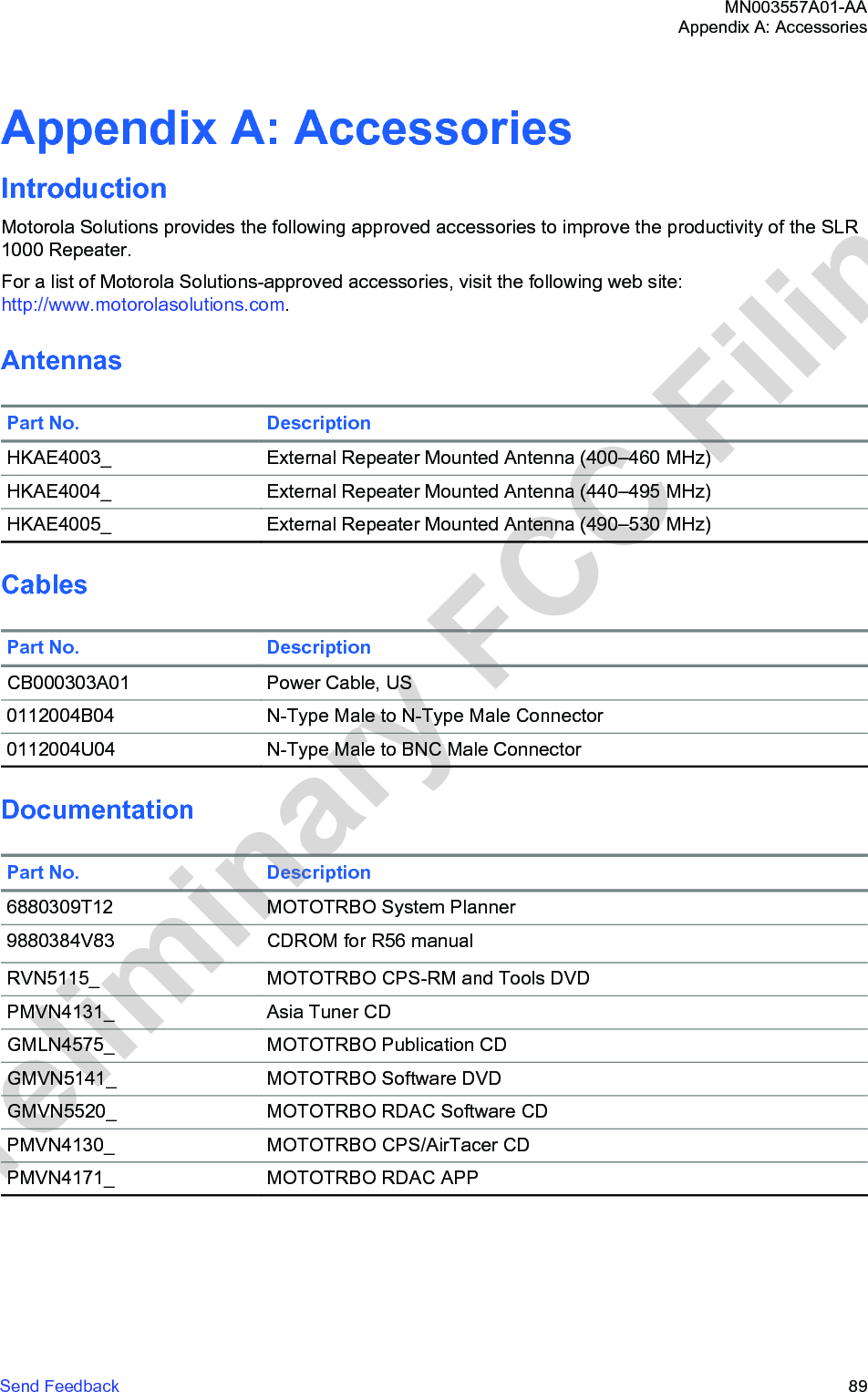
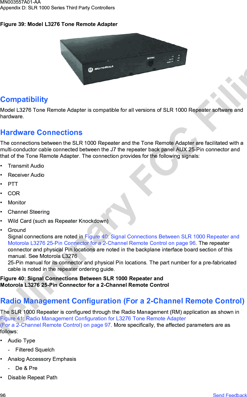
![Figure 45: Compliance Boundary for General Public (GP) and Ocupational (OCC) ExposureProduct Put In ServiceSome regulations require that additional exposure assessments be performed when putting theproduct in service, to account for antenna site-specific circumstances such as the environment (such as, electromagnetic scatterers) and other antennas. In such cases, certain standards [7]–[10]may need to be considered to determine the most suitable compliance assessment methodology.References1International Commission on Non-Ionizing Radiation Protection (ICNIRP), "Guideline for LimitingExposure to Time-Varying Electric, Magnetic, and Electromagnetic Fields", Health Physics, vol. 74,no. 4, pp. 494-522, April 1998.2United States Federal Communication Commission, "Evaluating compliance with FCC guidelinesfor human exposure to radio frequency electromagnetic fields", OET Bulletin 65, Ed. 97-01, Section2 (Prediction Methods), August 1997.3US Code of Federal Regulations, Title 47, Volume 1, Sec. 1.1310 Radio frequency radiationexposure limits (Revised as of October 1, 2003). http://edocket.access.gpo.gov/cfr_2003/octqtr/47cfr1.1310.htm.4EN 50383:2010. Basic standard for the calculation and measurement of electromagnetic fieldstrength and SAR related to human exposure from radio base stations and fixed terminal stationsfor wireless telecommunication systems (110 MHz–40 GHz). CENELEC (European Committee forElectrotechnical Standardization).5EN 50384:2002. Product standard to demonstrate the compliance of radio base stations and fixedterminal stations for wireless telecommunication systems with the basic restrictions or the referencelevels related to human exposure to radio frequency electromagnetic fields MN003557A01-AAAppendix E: MOTOTRBO Repeater EME Assessment106 Send FeedbackPreliminary FCC Filing](https://usermanual.wiki/Motorola-Solutions/99FT4100/User-Guide-3392771-Page-106.png)