Motorola Solutions 99FT4100 Non-Broadcast Transmitter User Manual Exhibit D Users Manual per 2 1033 c3
Motorola Solutions, Inc. Non-Broadcast Transmitter Exhibit D Users Manual per 2 1033 c3
Exhibit D Users Manual per 2 1033 c3

SLR 1000 Repeater
Basic Service &
Installation Manual
MOTOTRBO™ REPEATER
PROFESSIONAL DIGITAL TWO-WAY RADIO SYSTEM
*MN003557A01*
MN003557A01-AA
JUNE 2017
© 2017 Motorola Solutions, Inc. All rights reserved
Preliminary FCC Filing
Preliminary FCC Filing

Notice
Foreword
This manual covers all versions of the MOTOTRBO SLR 1000 Repeater, unless otherwise specified. It
includes all the information necessary to maintain peak product performance and maximum working
time, using levels 1 and 2 maintenance procedures. These levels of service go down to software
issues or replacement of an accessory, which are commonly performed by local service centers,
Motorola Solutions Authorized Dealers, self-maintained customers, and distributors.
CAUTION: These servicing instructions are for use by qualified personnel only. To reduce the
risk of electric shock, do not perform any servicing other than that contained in the Operating
Instructions unless you are qualified to do so. Refer all servicing to qualified service personnel.
General Safety Precautions
For more information, see General Safety and Installation
Standards and Guidelines.
Computer Software Copyrights
The Motorola Solutions products described in this manual may include copyrighted Motorola Solutions
computer programs stored in semiconductor memories or other media. Laws in the United States and
other countries preserve for Motorola Solutions certain exclusive rights for copyrighted computer
programs, including, but not limited to, the exclusive right to copy or reproduce in any form the
copyrighted computer program. Accordingly, any copyrighted Motorola Solutions computer programs
contained in the Motorola Solutions products described in this manual may not be copied, reproduced,
modified, reverse-engineered, or distributed in any manner without the express written permission of
Motorola Solutions.
Furthermore, the purchase of Motorola Solutions products shall not be deemed to grant either directly
or by implication, estoppel, or otherwise, any license under the copyrights, patents or patent
applications of Motorola Solutions, except for the normal non-exclusive license to use that arises by
operation of law in the sale of a product.
Document Copyrights
No duplication or distribution of this document or any portion thereof shall take place without the
express written permission of Motorola Solutions.
No part of this manual may be reproduced, distributed, or transmitted in any form or by any means,
electronic or mechanical, for any purpose without the express written permission of Motorola Solutions.
Disclaimer
The information in this document is carefully examined, and is believed to be entirely reliable.
However, no responsibility is assumed for inaccuracies. Furthermore, Motorola Solutions reserves the
right to make changes to any products herein to improve readability, function, or design. Motorola
Solutions does not assume any liability arising out of the applications or use of any product or circuit
described herein; nor does it cover any license under its patent rights nor the rights of others.
Controlled copies of this document is available through Motorola Solutions On-Line (MOL).
MN003557A01-AA
Foreword
Send Feedback 3
Preliminary FCC Filing
Trademarks
MOTOROLA, MOTO, MOTOROLA SOLUTIONS and the Stylized M logo are trademarks or registered
trademarks of Motorola Trademark Holdings, LLC and are used under license. All other trademarks are
the property of their respective owners.
© 2017 Motorola Solutions, Inc.
All rights reserved.
MN003557A01-AA
Notice Foreword
4 Send Feedback
Preliminary FCC Filing

Notice
General Safety and Installation
Standards and Guidelines
ATTENTION!
WARNING: For safe installation, operation, service and repair of this equipment, follow the
safety precautions and instructions described below, as well as any additional safety
information in Motorola Solutions product service and installation manuals and the Motorola
Solutions R56 Standards and Guidelines for Communications Sites manual (which can be
obtained by ordering CDROM 9880384V83). To obtain copies of these materials, please
contact Motorola Solutions as directed at the end of this section. After installation, these
instructions should be retained and readily available for any person operating or servicing this
repeater or working near it.
Failure to follow these safety precautions and instructions could result in serious injury or property
damage.
The installation process requires preparation and knowledge of the site before installation begins.
Review installation procedures and precautions in the Motorola Solutions R56 manual before
performing any site or component installation. Personnel must use safe work practices and good
judgment, and always follow applicable safety procedures, such as requirements of the Occupational
Safety and Health Administration (OSHA), the National Electrical Code (NEC), and local codes.
The following are additional general safety precautions that must be observed:
• To continue compliance with any applicable regulations and maintain the safety of this equipment,
do not install substitute parts or perform any unauthorized modifications.
• All equipment must be serviced by Motorola Solutions trained personnel.
• If troubleshooting the equipment while the power is on, be aware of live circuits which could contain
hazardous voltage.
• Do not operate the radio transmitters unless all RF connectors are secure and all connectors are
properly terminated.
• All equipment must be properly grounded in accordance with the Motorola Solutions R56 and
specified installation instructions for safe operation.
• Openings between the fins on the chassis are provided for ventilation. Do not block or cover
openings between the fins that protect the devices from overheating.
•Some equipment components can become extremely hot during operation. Turn off all power
to the equipment and wait until sufficiently cool before touching.
•Maintain emergency first aid kits at the site.
• Never store combustible materials in or near equipment. The combination of combustible material,
heat and electrical energy increases the risk of a fire hazard.
• Equipment shall be installed in a site that meets the requirements of a
“restricted access location,” per (UL60950-1 & EN60950-1), which is defined as follows: "Access
can only be gained by service persons or by users who have been instructed about the reasons for
the restrictions applied to the location and about any precautions that shall be taken; and access is
through the use of a tool or lock and key, or other means of security, and is controlled by the
authority responsible for the location."
MN003557A01-AA
General Safety and Installation
Standards and Guidelines
Send Feedback 5
Preliminary FCC Filing

• Ensure that the installation area can safely support the weight of the repeater.
• Burn hazard. The metal housing of the product may become extremely hot. Use caution
when working around the equipment.
•RF energy burn hazard. Disconnect power in the cabinet to prevent injury before
disconnecting and connecting antennas.
•Shock hazard. The outer shields of all Tx and Rx RF cables outer shields must be grounded per
Motorola Solutions R56 manual.
• All Tx and Rx RF cables shall be connected to a surge protection device according to Motorola
Solutions R56 manual. Do not connect Tx and Rx RF cables directly to an outside antenna.
•
Attention
Compliance with National and International standards and guidelines for human exposure to
Electromagnetic Energy (EME) at Transmitter Antenna sites generally requires that persons having
access to a site shall be aware of the potential for exposure to EME and can exercise control of
exposure by appropriate means, such as adhering to warning sign instructions. See this installation
manual and Appendix A of Motorola Solutions R56.
This product complies with the requirements set forth by the European R&TTE regulations and
applicable CENELEC standards concerning human exposure to Electromagnetic Energy (EME) at
Transmitter Antenna sites. Appendix E: MOTOTRBO Repeater EME Assessment on page 99 in
this manual includes an EME exposure analysis of a typical system configuration for this product.
For a different system configuration than the typical configuration, compliance with applicable EME
exposure standards (current versions of the EN50384, EN50385, IEC/IEEE 62704-2, and United
States Federal Communication Commission, “Evaluating compliance with FCC guidelines for
human exposure to radio frequency electromagnetic fields,” OET Bulletin 65 (Ed. 97-01), August
1997. Supplement C (Edition 01-01) to US FCC OET Bulletin 65 (Edition 97-01), “Additional
Information for Evaluating Compliance of Mobile and Portable Devices with FCC Limits for Human
Exposure to Radio frequency Emissions,” June 2001 standards for occupational and general public
exposure, respectively) can be evaluated by either employing the indoor or outdoor methods
illustrated in the typical system configuration EME exposure analysis included in Appendix E:
MOTOTRBO Repeater EME Assessment on page 99 in this manual, or employing another
suitable method among those described in the current version of the EN50383 standard.
Once the occupational and general public compliance boundaries are determined, means to ensure
that workers and people are outside the respective boundaries, for instance using appropriate
signage or restricted access, should be implemented; if this is not possible or practically achievable
for the specific system configuration, the configuration should be modified in order to make it
possible. The R56 Standards and Guidelines for Communications Sites manual (which can be
obtained by ordering CDROM 9880384V83) provides examples of signage that can be used to
identify the occupational or general public compliance boundaries.
Refer to product specific manuals for detailed safety and installation instructions. Manuals can be
obtained with product orders, downloaded from https://businessonline.motorolasolutions.com, or
purchased through the Motorola Solutions Aftermarket & Accessory Department.
This is a class A product. In a domestic environment, this product may cause radio interference in
which case the user may be required to take adequate measures.
MN003557A01-AA
Notice General Safety and Installation
Standards and Guidelines
6 Send Feedback
Preliminary FCC Filing

Notice
MOTOTRBO SLR 1000 Repeater
Supplemental Safety and Installation
Requirements
ATTENTION!
The MOTOTRBO SLR 1000 Repeater must be installed in a suitable, in-building location, or suitable
outdoor location. A restricted access location is required when installing this equipment into the end
system.
When installing the equipment, all requirements of relevant standards and local electrical codes must
be fulfilled.
The maximum operating ambient temperature of this equipment is 60 °C. The maximum operating
altitudes are supported, up to 2000 meters above sea level. Reduced performance above 2000 meters
may result.
MN003557A01-AA
MOTOTRBO SLR 1000 Repeater
Supplemental Safety and Installation Requirements
Send Feedback 7
Preliminary FCC Filing
This page intentionally left blank.
Preliminary FCC Filing

Notice
Environmental Information
Material Content
NOTICE:
•The Motorola Solutions MOTOTRBO SLR 1000 Repeater system and its subsystems have
been created in compliance with the environmental goals of the European Union's
Restriction of Hazardous Substances (RoHS 2) Directive 2011/65/EU and the Waste
Electrical and Electronic Equipment (WEEE) Directive 2012/19/EU as well as Motorola
Solutions corporate goals to minimize environmental impact of its products.
• This Motorola Solutions policy is reflected throughout the entire design, procurement,
assembly, and packaging process.
• In support of these efforts to provide environmentally-responsible products, please comply
with the information in the following sections regarding product disposal for systems being
replaced.
Disposal of your Electronic and Electric Equipment
Do not dispose of electronic and electric equipment or electronic and electric accessories with your
household waste. In some countries or regions, collection systems have been set up to handle waste
of electrical and electronic equipment.
In European Union countries, contact your local equipment supplier representative or service center for
information about the waste collection system in your country.
Disposal Guideline
The European Union's WEEE directive symbol on a Motorola Solutions product indicates that the
product should not be disposed of with household waste.
MN003557A01-AA
Environmental Information
Send Feedback 9
Preliminary FCC Filing
This page intentionally left blank.
Preliminary FCC Filing

Document History
The following major changes have been implemented in this manual since the previous edition:
Edition Description Date
MN003557A01-AA Initial release of the MOTOTRBO SLR 1000 Re-
peater Basic Service & Installation manual
June 2017
MN003557A01-AA
Document History
Send Feedback 11
Preliminary FCC Filing
This page intentionally left blank.
Preliminary FCC Filing
Contents
Document History..................................................................................................... 11
List of Figures............................................................................................................19
List of Tables............................................................................................................. 21
List of Procedures.....................................................................................................23
Related Publications.................................................................................................25
Summary of Bands Available...................................................................................27
Chapter 1: SLR 1000 Repeater.................................................................................33
1.1 Notations Used in This Manual..............................................................................................33
1.2 Description.............................................................................................................................33
1.3 Operating Features................................................................................................................35
1.4 Frequency Ranges and Power Levels...................................................................................36
1.5 Specifications.........................................................................................................................36
1.6 Theory of Operation...............................................................................................................39
1.7 Basic Repeater Level Troubleshooting – RDAC and LEDs...................................................40
1.8 SLR 1000 Repeater Model Numbering Scheme................................................................... 42
1.9 UHF High Power Model Chart............................................................................................... 42
Chapter 2: SLR 1000 Satellite Receiver.................................................................. 43
2.1 Description.............................................................................................................................43
2.2 Operating Features................................................................................................................43
2.3 Frequency Ranges................................................................................................................ 43
2.4 Specifications.........................................................................................................................43
2.5 Configuration......................................................................................................................... 43
2.6 Basic Station Level Troubleshooting – RDAC and LEDs...................................................... 44
2.7 Model Chart........................................................................................................................... 44
Chapter 3: SLR 1000 Transceiver Board.................................................................45
3.1 Description.............................................................................................................................45
3.1.1 General Description................................................................................................. 45
3.1.2 Input and Output Connections................................................................................. 45
3.1.3 Frequency Bands.....................................................................................................46
3.2 Receiver Subsystem..............................................................................................................46
3.2.1 Specifications...........................................................................................................46
3.3 Transmitter Subsystem..........................................................................................................47
3.3.1 Specifications...........................................................................................................47
3.4 Station Control Subsystem.................................................................................................... 47
3.4.1 Audio........................................................................................................................48
MN003557A01-AA
Contents
Send Feedback 13
Preliminary FCC Filing
3.5 Station Control Interface........................................................................................................ 49
3.5.1 Bottom Panel Connections...................................................................................... 49
3.5.2 Expansion Board Interface Connector..................................................................... 49
Chapter 4: SLR 1000 Front Panel............................................................................ 51
4.1 Description.............................................................................................................................51
Chapter 5: SLR 1000 Bottom Panel......................................................................... 53
5.1 Description.............................................................................................................................53
5.1.1 General Description................................................................................................. 53
5.2 Bottom Panel Interfaces........................................................................................................ 53
5.2.1 DC Power Inlet.........................................................................................................54
5.2.2 USB..........................................................................................................................54
5.2.3 Ethernet................................................................................................................... 54
5.2.4 Auxiliary (Aux)/Accessory........................................................................................ 55
Chapter 6: SLR 1000 Test Equipment And Service Aids.......................................57
6.1 Recommended Test Equipment............................................................................................ 57
6.2 Service Aids...........................................................................................................................57
Chapter 7: SLR 1000 Performance Check or Testing............................................ 59
7.1 General.................................................................................................................................. 59
7.2 Transmitter Testing................................................................................................................59
7.2.1 Introduction.............................................................................................................. 59
7.2.2 Test Equipment........................................................................................................59
7.2.3 Verifying Transmitter Circuitry..................................................................................60
7.3 Receiver Testing....................................................................................................................61
7.3.1 Introduction.............................................................................................................. 61
7.3.2 Required Test Equipment........................................................................................ 62
7.3.3 Verifying Receiver Circuitry......................................................................................62
Chapter 8: SLR 1000 Programming and Tuning.....................................................65
8.1 Introduction............................................................................................................................ 65
8.2 Radio Management Setup..................................................................................................... 65
8.3 Reference Oscillator Alignment............................................................................................. 66
8.3.1 Tuning the Reference Oscillator.............................................................................. 66
8.4 Repeater Tuning Setup..........................................................................................................66
8.5 Rx Audio Level Set................................................................................................................ 67
8.5.1 Tuning the Rx Audio Level Set................................................................................ 67
8.6 Tx Audio Level Set.................................................................................................................68
8.6.1 Tuning the Tx Audio Level Set.................................................................................68
8.7 Modulation Limit Alignment....................................................................................................69
8.7.1 Tuning the Modulation Limit (with no Tx Data and no PL)....................................... 69
8.7.2 Verifiying the Modulation Limit (with no Tx Data and no PL)................................... 69
MN003557A01-AA
Contents
14 Send Feedback
Preliminary FCC Filing
Chapter 9: SLR 1000 Maintenance and Disassembly/Reassembly...................... 71
9.1 Introduction............................................................................................................................ 71
9.2 Routine Maintenance.............................................................................................................71
9.3 Preventive Maintenance........................................................................................................ 72
9.3.1 Inspection.................................................................................................................72
9.3.2 Cleaning Procedures............................................................................................... 72
9.4 Safe Handling of CMOS and LDMOS Devices......................................................................72
9.5 Installing a Duplexer.............................................................................................................. 73
9.6 Installing a High-Speed Solid-State Antenna Switch............................................................. 75
Chapter 10: SLR 1000 Installation........................................................................... 77
10.1 Pre-Installation Considerations............................................................................................77
10.1.1 Installation Overview..............................................................................................77
10.1.2 Site Environmental Conditions...............................................................................77
10.1.3 Equipment Ventilation............................................................................................ 78
10.1.3.1 Ventilation for a Ceiling Mount................................................................. 78
10.1.3.2 Ventilation for a Wall Mount..................................................................... 78
10.1.4 AC and DC Input Power Requirements................................................................. 79
10.1.4.1 DC Input Power Requirements................................................................ 79
10.1.4.2 AC Input Power Requirements.................................................................79
10.1.4.3 Ground Connection.................................................................................. 79
10.1.4.4 Battery Connection...................................................................................79
10.1.4.5 RF Antenna Connections......................................................................... 80
10.1.4.6 System Cable Connections......................................................................80
10.1.5 Equipment Mounting Methods............................................................................... 80
10.1.6 Site Grounding and Lightning Protection............................................................... 80
10.1.6.1 Electrical Ground......................................................................................81
10.1.6.2 RF Ground............................................................................................... 81
10.1.6.3 Lightning Ground......................................................................................81
10.1.6.4 Equipment Grounding.............................................................................. 81
10.1.7 Recommended Tools and Equipment....................................................................81
10.1.8 Equipment Unpacking and Inspection................................................................... 82
10.1.8.1 Unpack Equipment...................................................................................82
10.1.8.2 Initial Inspection....................................................................................... 82
10.2 Mechanical Installation........................................................................................................ 82
10.2.1 SLR 1000 Repeater Package Contents.................................................................82
10.2.2 Mounting the SLR 1000 Repeater to a Wall or Ceiling.......................................... 83
10.2.3 Mounting the SLR 1000 Repeater to a Pole.......................................................... 83
10.3 Electrical Connections......................................................................................................... 84
10.3.1 Power Supply Connections....................................................................................85
MN003557A01-AA
Contents
Send Feedback 15
Preliminary FCC Filing
10.3.1.1 DC Input Power Connection/ DC Power Connection............................... 85
10.3.1.2 AC Input Power Connection.....................................................................85
10.3.1.3 Ground Connection.................................................................................. 86
10.3.1.4 RF Antenna Connections......................................................................... 86
10.3.1.5 System Cable Connections......................................................................86
10.3.2 Installing Cable Grommet Connectors or Plugs.....................................................86
10.4 Post Installation Checklist....................................................................................................87
10.4.1 Apply Power...........................................................................................................87
10.4.2 Verify Proper Operation......................................................................................... 87
10.4.3 Front Panel LEDs...................................................................................................87
10.4.4 Repeater Codeplug Data Backup.......................................................................... 88
10.5 General Bonding and Grounding Requirements..................................................................88
10.6 General Cabling Requirements........................................................................................... 88
Appendix A: Accessories.........................................................................................89
Introduction.................................................................................................................................. 89
Antennas...........................................................................................................................89
Cables...............................................................................................................................89
Documentation..................................................................................................................89
Duplexers..........................................................................................................................90
Mounting........................................................................................................................... 90
Service Tools.................................................................................................................... 90
Appendix B: Replacement Parts Ordering............................................................. 91
Replacement Parts Ordering....................................................................................................... 91
Basic Ordering Information............................................................................................... 91
Motorola Solutions Online.................................................................................................91
Mail Orders....................................................................................................................... 91
Telephone Orders............................................................................................................. 91
Fax Orders........................................................................................................................ 92
Parts Identification............................................................................................................ 92
Product Customer Service................................................................................................ 92
Appendix C: Motorola Solutions Service Centers................................................. 93
Motorola Solutions Service Centers............................................................................................ 93
Servicing Information........................................................................................................ 93
Motorola Solutions Service Center................................................................................... 93
Motorola Solutions Federal Technical Center...................................................................93
Motorola Canadian Technical Logistics Center................................................................ 93
Appendix D: SLR 1000 Series Third Party Controllers..........................................95
Overview......................................................................................................................................95
Tone Remote Adapter................................................................................................................. 95
MN003557A01-AA
Contents
16 Send Feedback
Preliminary FCC Filing
Compatibility..................................................................................................................... 96
Hardware Connections..................................................................................................... 96
Radio Management Configuration (For a 2-Channel Remote Control).............................96
Tone Remote Adapter Settings.........................................................................................97
Radio Rx................................................................................................................ 97
Radio Tx.................................................................................................................98
Channel Steering................................................................................................... 98
Monitoring.............................................................................................................. 98
PTT........................................................................................................................ 98
Wildcard 1 (optional).............................................................................................. 98
Appendix E: MOTOTRBO Repeater EME Assessment..........................................99
Executive Summary.....................................................................................................................99
Device Power Characteristics......................................................................................................99
Outdoor Exposure Prediction Model..........................................................................................100
Whole-Body SAR Compliance........................................................................................ 100
Peak 1-g Average SAR Compliance...............................................................................101
Indoor Exposure Prediction Model.............................................................................................102
Exposure in Front of the Antenna................................................................................... 102
Exposure at Ground Level.............................................................................................. 103
Typical System Configuration.................................................................................................... 104
Exposure Limits......................................................................................................................... 104
EME Exposure Evaluation......................................................................................................... 105
Exposure in Front of the Antenna................................................................................... 105
Exposure at Ground Level.............................................................................................. 105
Compliance Boundary Description............................................................................................ 105
Product Put In Service............................................................................................................... 106
References................................................................................................................................ 106
Glossary of Terms and Acronyms.........................................................................109
MN003557A01-AA
Contents
Send Feedback 17
Preliminary FCC Filing
This page intentionally left blank.
Preliminary FCC Filing
List of Figures
Figure 1: SLR 1000 Repeater Bottom View........................................................................................... 34
Figure 2: SLR 1000 Repeater Left View.................................................................................................34
Figure 3: SLR 1000 Repeater Right View.............................................................................................. 34
Figure 4: SLR 1000 Repeater Bottom View........................................................................................... 34
Figure 5: SLR 1000 Repeater Front View.............................................................................................. 34
Figure 6: SLR 1000 Repeater Front View (without top cover)................................................................34
Figure 7: RDAC Diagnostic Screen........................................................................................................ 40
Figure 8: SLR 1000 Repeater Model Numbering Scheme..................................................................... 42
Figure 9: Operation Mode Configuration for Satellite Receiver Functionality.........................................44
Figure 10: SLR 1000 Repeater Transceiver Board Connector Locations.............................................. 45
Figure 11: SLR 1000 Repeater Audio Block Diagram............................................................................ 48
Figure 12: SLR 1000 Repeater Bottom Panel Connector Names and Locations...................................53
Figure 13: DC Power Inlet Connector.....................................................................................................54
Figure 14: USB Connector..................................................................................................................... 54
Figure 15: Ethernet Connector............................................................................................................... 54
Figure 16: Auxiliary/Accessory Connector..............................................................................................55
Figure 17: Test Equipment Setup for Verifying Transmitter Circuitry..................................................... 61
Figure 18: Test Equipment Setup for Verifying Receiver Circuitry......................................................... 63
Figure 19: Radio Management Setup.....................................................................................................65
Figure 20: Bottom View of SLR 1000 Repeater..................................................................................... 65
Figure 21: Tx Menu Tree (Ref. Oscillator).............................................................................................. 66
Figure 22: SLR 1000 Repeater Tuning Equipment Setup...................................................................... 67
Figure 23: RX Menu tree (Rx Rated Volume).........................................................................................67
Figure 24: Auxiliary Connector............................................................................................................... 68
Figure 25: Tx Menu Tree (Tx Rated Volume).........................................................................................68
Figure 26: TX Menu Tree (Tuning Procedure with No Tx Data).............................................................69
Figure 27: SLR 1000 Repeater Front View (without top cover)..............................................................74
Figure 28: SLR 1000 Repeater Front View (without top cover) with a Duplexer.................................... 74
Figure 29: SLR 1000 Repeater Front View (without top cover)..............................................................75
Figure 30: SLR 1000 Repeater Front View (without top cover) with an Antenna Switch....................... 76
Figure 31: Bracket Mounting Holes........................................................................................................ 83
Figure 32: Location of Repeater M6 Screw Mounts............................................................................... 83
Figure 33: Bracket Receiving Slots........................................................................................................ 83
Figure 34: U-Bolt Bracket Assembly.......................................................................................................84
Figure 35: Location of Repeater M6 Screw Mounts............................................................................... 84
Figure 36: Bracket Receiving Slots........................................................................................................ 84
MN003557A01-AA
List of Figures
Send Feedback 19
Preliminary FCC Filing
Figure 37: SLR 1000 Repeater Bottom Panel Connector Names and Locations...................................84
Figure 38: Radio Management Settings to Configure SLR 1000 Repeater for Analog Mode................ 95
Figure 39: Model L3276 Tone Remote Adapter..................................................................................... 96
Figure 40: Signal Connections Between SLR 1000 Repeater and
Motorola L3276 25-Pin Connector for a 2-Channel Remote Control.................................................96
Figure 41: Radio Management Configuration for L3276 Tone Remote Adapter
(For a 2-Channel Remote Control).................................................................................................... 97
Figure 42: H-Field and SAR Distributions for Exposure from a Dipole Antenna.................................. 100
Figure 43: Reference Frame for the Point of Interest (POI) Cylindrical Co-Ordinates......................... 102
Figure 44: Schematic of the Ground-Level Exposure Model Adopted for the Assessment..................104
Figure 45: Compliance Boundary for General Public (GP) and Ocupational (OCC) Exposure............106
MN003557A01-AA
List of Figures
20 Send Feedback
Preliminary FCC Filing
List of Tables
Table 1: SLR 1000 Repeater Bottom View Callout Legend................................................................... 34
Table 2: SLR 1000 Repeater Left View Callout Legend.........................................................................34
Table 3: SLR 1000 Repeater Right View Callout Legend...................................................................... 34
Table 4: SLR 1000 Repeater Front View Callout Legend...................................................................... 34
Table 5: SLR 1000 Repeater Front View (without top Cover) Callout Legend....................................... 34
Table 6: SLR 1000 Frequency Ranges and Power Levels.....................................................................36
Table 7: SLR 1000 Repeater General Specifications (All Bands).......................................................... 36
Table 8: SLR 1000 Repeater Specifications...........................................................................................37
Table 9: SLR 1000 Repeater Front Panel LED Indicators......................................................................40
Table 10: SLR 1000 Front Panel LED Definitions.................................................................................. 41
Table 11: SLR 1000 Repeater Front View (without top Cover) Callout Legend..................................... 45
Table 12: Specifications of Receiver Subsystem................................................................................... 46
Table 13: Specifications of Transmitter Exciter Subsystem................................................................... 47
Table 14: SLR 1000 Repeater Connector Types and Primary Functions.............................................. 53
Table 15: DC Power Inlet Connector Callout Legend.............................................................................54
Table 16: USB Connector Callout Legend............................................................................................. 54
Table 17: Ethernet Connector Callout Legend....................................................................................... 54
Table 18: Auxiliary/Accessory Connector Callout Legend......................................................................55
Table 19: Recommended Test Equipment............................................................................................. 57
Table 20: Service Aids............................................................................................................................57
Table 21: Bottom View of the SLR 1000 Repeater Callout Legend....................................................... 65
Table 22: SLR 1000 Repeater Front View (without top Cover) Callout Legend..................................... 74
Table 23: SLR 1000 Repeater Front View (without top Cover) with a Duplexer Callout Legend........... 74
Table 24: SLR 1000 Repeater Front View (without top Cover) Callout Legend..................................... 75
Table 25: SLR 1000 Repeater Front View (without top Cover) with an Antenna Switch Callout
Legend...............................................................................................................................................76
Table 26: SLR 1000 Repeater Package Contents................................................................................. 82
Table 27: SLR 1000 Repeater Connector Types and Primary Functions.............................................. 84
Table 28: Indoor EME Compliance Distances Based on Example UHF Evaluation.............................. 99
Table 29: Outdoor EME Compliance Distances Based on Example UHF Evaluation............................99
Table 30: Whole-Body Average SAR Results...................................................................................... 100
MN003557A01-AA
List of Tables
Send Feedback 21
Preliminary FCC Filing
This page intentionally left blank.
Preliminary FCC Filing
List of Procedures
Verifying Transmitter Circuitry ............................................................................................................... 60
Verifying Receiver Circuitry ................................................................................................................... 62
Tuning the Reference Oscillator ............................................................................................................ 66
Tuning the Rx Audio Level Set .............................................................................................................. 67
Tuning the Tx Audio Level Set .............................................................................................................. 68
Tuning the Modulation Limit (with no Tx Data and no PL) .....................................................................69
Verifiying the Modulation Limit (with no Tx Data and no PL) .................................................................69
Installing a Duplexer .............................................................................................................................. 73
Installing a High-Speed Solid-State Antenna Switch .............................................................................75
Mounting the SLR 1000 Repeater to a Wall or Ceiling ..........................................................................83
Mounting the SLR 1000 Repeater to a Pole ..........................................................................................83
Installing Cable Grommet Connectors or Plugs .................................................................................... 86
MN003557A01-AA
List of Procedures
Send Feedback 23
Preliminary FCC Filing
This page intentionally left blank.
Preliminary FCC Filing

Related Publications
Related Publications Part No.
MOTOTRBO SLR 1000 Quick Start Guide MN003581A01
MN003557A01-AA
Related Publications
Send Feedback 25
Preliminary FCC Filing
This page intentionally left blank.
Preliminary FCC Filing

Summary of Bands Available
Table below lists the SLR 1000 Repeater bands available in this manual.
For details, see UHF High Power Model Chart on page 42.
Frequency Band Bandwidth Power Level
UHF 400 – 527 MHz 1 – 10 W
MN003557A01-AA
Summary of Bands Available
Send Feedback 27
Preliminary FCC Filing
This page intentionally left blank.
Preliminary FCC Filing

Notice
Commercial Warranty
Limited Warranty
MOTOROLA COMMUNICATION PRODUCTS
I. What This Warranty Covers And For How Long
MOTOROLA SOLUTIONS INC. (“MOTOROLA”) warrants the MOTOROLA manufactured
Communication Products listed below (“Product”) against defects in material and workmanship under
normal use and service for a period of time from the date of purchase as scheduled below:
Repeater Two (2) Years
Product Accessories One (1) Year
Motorola, at its option, will at no charge either repair the Product (with new or reconditioned parts),
replace it (with a new or reconditioned Product), or refund the purchase price of the Product during the
warranty period provided it is returned in accordance with the terms of this warranty. Replaced parts or
boards are warranted for the balance of the original applicable warranty period. All replaced parts of
Product shall become the property of MOTOROLA.
This express limited warranty is extended by MOTOROLA to the original end user purchaser only and
is not assignable or transferable to any other party. This is the complete warranty for the Product
manufactured by MOTOROLA. MOTOROLA assumes no obligations or liability for additions or
modifications to this warranty unless made in writing and signed by an officer of MOTOROLA. Unless
made in a separate agreement between MOTOROLA and the original end user purchaser,
MOTOROLA does not warrant the installation, maintenance or service of the Product.
MOTOROLA cannot be responsible in any way for any ancillary equipment not furnished by
MOTOROLA which is attached to or used in connection with the Product, or for operation of the
Product with any ancillary equipment, and all such equipment is expressly excluded from this warranty.
Because each system which may use the Product is unique, MOTOROLA disclaims liability for range,
coverage, or operation of the system as a whole under this warranty.
II. General Provisions
This warranty sets forth the full extent of MOTOROLA's responsibilities regarding the Product. Repair,
replacement or refund of the purchase price, at MOTOROLA's option, is the exclusive remedy. THIS
WARRANTY IS GIVEN IN LIEU OF ALL OTHER EXPRESS WARRANTIES. IMPLIED WARRANTIES,
INCLUDING WITHOUT LIMITATION, IMPLIED WARRANTIES OF MERCHANTABILITY AND
FITNESS FOR A PARTICULAR PURPOSE, ARE LIMITED TO THE DURATION OF THIS LIMITED
WARRANTY. IN NO EVENT SHALL MOTOROLA BE LIABLE FOR DAMAGES IN EXCESS OF THE
PURCHASE PRICE OF THE PRODUCT, FOR ANY LOSS OF USE, LOSS OF TIME,
INCONVENIENCE, COMMERCIAL LOSS, LOST PROFITS OR SAVINGS OR OTHER INCIDENTAL,
SPECIAL OR CONSEQUENTIAL DAMAGES ARISING OUT OF THE USE OR INABILITY TO USE
SUCH PRODUCT, TO THE FULL EXTENT SUCH MAY BE DISCLAIMED BY LAW.
III. State Law Rights
SOME STATES DO NOT ALLOW THE EXCLUSION OR LIMITATION OF INCIDENTAL OR
CONSEQUENTIAL DAMAGES OR LIMITATION ON HOW LONG AN IMPLIED WARRANTY LASTS,
SO THE ABOVE LIMITATION OR EXCLUSIONS MAY NOT APPLY.
MN003557A01-AA
Commercial Warranty
Send Feedback 29
Preliminary FCC Filing
This warranty gives specific legal rights, and there may be other rights which may vary from state to
state
IV. How To Get Warranty Service
You must provide proof of purchase (bearing the date of purchase and Product item serial number) in
order to receive warranty service and, also, deliver or send the Product item, transportation and
insurance prepaid, to an authorized warranty service location. Warranty service will be provided by
Motorola through one of its authorized warranty service locations. If you first contact the company
which sold you the Product, it can facilitate your obtaining warranty service. You can also .
V. What This Warranty Does Not Cover
Defects or damage resulting from use of the Product in other than its normal and customary manner.
Defects or damage from misuse, accident, water, or neglect.
Defects or damage from improper testing, operation, maintenance, installation, alteration, modification,
or adjustment.
Breakage or damage to antennas unless caused directly by defects in material workmanship.
A Product subjected to unauthorized Product modifications, disassemblies or repairs (including, without
limitation, the addition to the Product of non-Motorola supplied equipment) which adversely affect
performance of the Product or interfere with Motorola's normal warranty inspection and testing of the
Product to verify any warranty claim.
Product which has had the serial number removed or made illegible.
Freight costs to the repair depot.
A Product which, due to illegal or unauthorized alteration of the software/firmware in the Product, does
not function in accordance with MOTOROLA’s published specifications or the FCC type acceptance
labeling in effect for the Product at the time the Product was initially distributed from MOTOROLA.
Scratches or other cosmetic damage to Product surfaces that does not affect the operation of the
Product.
Normal and customary wear and tear.
VI. Patent And Software Provisions
MOTOROLA will defend, at its own expense, any suit brought against the end user purchaser to the
extent that it is based on a claim that the Product or parts infringe a United States patent, and
MOTOROLA will pay those costs and damages finally awarded against the end user purchaser in any
such suit which are attributable to any such claim, but such defense and payments are conditioned on
the following:
that MOTOROLA will be notified promptly in writing by such purchaser of any notice of such claim;
that MOTOROLA will have sole control of the defense of such suit and all negotiations for its
settlement or compromise; and
should the Product or parts become, or in MOTOROLA's opinion be likely to become, the subject of a
claim of infringement of a United States patent, that such purchaser will permit MOTOROLA, at its
option and expense, either to procure for such purchaser the right to continue using the Product or
parts or to replace or modify the same so that it becomes noninfringing or to grant such purchaser a
credit for the Product or parts as depreciated and accept its return. The depreciation will be an equal
amount per year over the lifetime of the Product or parts as established by MOTOROLA.
MOTOROLA will have no liability with respect to any claim of patent infringement which is based upon
the combination of the Product or parts furnished hereunder with software, apparatus or devices not
furnished by MOTOROLA, nor will MOTOROLA have any liability for the use of ancillary equipment or
software not furnished by MOTOROLA which is attached to or used in connection with the Product.
The foregoing states the entire liability of MOTOROLA with respect to infringement of patents by the
Product or any parts thereof.
MN003557A01-AA
Notice Commercial Warranty
30 Send Feedback
Preliminary FCC Filing
Laws in the United States and other countries preserve for MOTOROLA certain exclusive rights for
copyrighted MOTOROLA software such as the exclusive rights to reproduce in copies and distribute
copies of such Motorola software. MOTOROLA software may be used in only the Product in which the
software was originally embodied and such software in such Product may not be replaced, copied,
distributed, modified in any way, or used to produce any derivative thereof. No other use including,
without limitation, alteration, modification, reproduction, distribution, or reverse engineering of such
MOTOROLA software or exercise of rights in such MOTOROLA software is permitted. No license is
granted by implication, estoppel or otherwise under MOTOROLA patent rights or copyrights.
VII. Governing Law
This Warranty is governed by the laws of the State of Illinois, USA.
MN003557A01-AA
Notice Commercial Warranty
Send Feedback 31
Preliminary FCC Filing
This page intentionally left blank.
Preliminary FCC Filing
Chapter 1
SLR 1000 Repeater
1.1
Notations Used in This Manual
Throughout the text in this publication, there are WARNING, CAUTION, and Note notations. These
notations are used to emphasize that safety hazards exist, and due care must be taken and observed.
NOTICE: An operational procedure, practice, or condition which is essential to emphasize.
CAUTION: CAUTION indicates a potentially hazardous situation which, if not avoided, might
result in equipment damage.
WARNING: WARNING indicates a potentially hazardous situation which, if not avoided, could
result in death or injury.
Symbol indicates areas of the product that pose potential burn hazards.
1.2
Description
The Motorola SLR 1000 Repeater provides a modular, flexible analog and digital station designed for
today's communication systems and for the future.
The station is available for use in these configurations:
•Analog Conventional
• Digital (MOTOTRBO)
• MOTOTRBO DMR Tier 2 Conventional – Single Site
• MOTOTRBO DMR Tier 2 Conventional – IP Site Connect
• MOTOTRBO Capacity Plus Trunking
• MOTOTRBO Connect Plus Trunking
• MOTOTRBO Capacity Max Trunking
• MOTOTRBO Digital Voting
NOTICE: Certain software features enabled through Radio Management can be configured with
the Online Help or with a regional representative. See the regional Ordering Guide to determine
the features available within the respective regions.
The repeater can either be configured as a stand-alone repeater or as a repeater connected to a
network, as in the case of operating in IP Site Connect mode. As a repeater, it listens on one uplink
frequency, and then re-transmits on a downlink frequency, thus providing the RF interface to the field
subscribers. When configured for analog station operation, the repeater is designed to operate with
most existing analog systems, which enables a smooth migration to the MOTOTRBO system.
When configured for digital operation, the repeater offers additional services. The digital repeater
operates in TDMA mode, which essentially divides one channel into two virtual channels using time
slots; therefore the user capacity is doubled. The repeater utilizes embedded signaling to inform the
field radios of the busy/idle status of each channel (time slot), the type of traffic, and even the source
and destination information.
MN003557A01-AA
SLR 1000 Repeater
Send Feedback 33
Preliminary FCC Filing

See the following figures and tables for connections, ports, LEDs, and their descriptions.
Figure 1: SLR 1000 Repeater Bottom View
Table 1: SLR 1000 Repeater Bottom View Callout Legend
Label Description
1 USB Port Programming Interface
2 Ethernet Port
3 Aux/Accessory Port
4 DC Power Inlet
5 Bonding Ground Connection
Figure 2: SLR 1000 Repeater Left View
Table 2: SLR 1000 Repeater Left View Callout Legend
Label Description
1 Receiver RF (Rx) Input
2 Option Dependent 1/GNSS
Option Dependent 2/WLAN
Figure 3: SLR 1000 Repeater Right View
Table 3: SLR 1000 Repeater Right View Callout Legend
Label Description
1 Transmitter RF (Tx) Input
2 Pressure Equalization Vent
Figure 4: SLR 1000 Repeater Bottom View
Figure 5: SLR 1000 Repeater Front View
Table 4: SLR 1000 Repeater Front View Callout Legend
Label Description
1 Status
2 Ethernet Link/Network Connectivity
3 Reference (for future use)
Figure 6: SLR 1000 Repeater Front View (without top cover)
Table 5: SLR 1000 Repeater Front View (without top Cover) Callout Legend
Label Description
1 Transmitter RF (Tx) Output
2 Pressure Equalizer Vent
Table continued…
MN003557A01-AA
Chapter 1: SLR 1000 Repeater
34 Send Feedback
Preliminary FCC Filing

Label Description
3 Receiver RF (Rx) Output
4 Transmitter RF (Tx) Input
5 Jumper Connection to enable external on/off function
6 Bonding Ground Connection
7 DC Power Inlet
8 Aux/Accessory Port
9 Ethernet Port
10 USB Port Programming Interface
11 Header Connection for optional antenna switch
12 Option Dependent 1 and 2
13 Expansion Board Connection (for future use)
14 Receiver RF (Rx) Input
15 Front Panel Flex Connector
1.3
Operating Features
The following are the standard features of an SLR 1000 Repeater model:
•MOTOTRBO Conventional Operation (2-Slot TDMA, 4FSK Modulation)
• Analog Conventional Operation (FM)
• Continuous Duty Cycle Operation over -30 °C to +60 °C
• Meets or exceeds the following standards:
• TIA603D
• ETSI 086
• ETSI 113
• ETSI TS 102 361-1 Part 1: DMR Air Interface Protocol
• ETSI TS 102 361-2 Part 2: DMR Voice and Generic Services and Facilities
• ETSI TS 102 361-3 Part 3: DMR Packet Data Protocol
• ETSI TS 102 361-4 Part 4: DMR Trunking Protocol
• Synthesized Frequency Generation
• Female N-type Antenna Connector (Tx)
• Female N-type Antenna Connector (Rx)
• Ethernet Port (Network)
• USB Port (Service)
• 4 configurable GPIO ports (Digital)
• 1 configurable GPI ports (Analog)
• 1 configurable GPO ports (Analog)
• 1.5 PPM Frequency Stability (Temperature AND 1-Year Aging) (VHF and UHF)
• Station Diagnostic Tests – Fixed Set of Tests run upon Start-up
MN003557A01-AA
Chapter 1: SLR 1000 Repeater
Send Feedback 35
Preliminary FCC Filing

• Physical Dimensions: 11" H x 9" W x 4" D (27.94 x 22.86 x 10.16 cm) without brackets or other
peripheral equipment
•Weight: 10 pounds (4.56 kg) excluding cabinet or other peripheral equipment
Motorola Solutions Network Interface:
• IP Site Connect
• Repeater Diagnostics and Control (RDAC)
• Capacity Plus
• Connect Plus
• Capacity Max
Third Party Controller Interface:
• Tone Remote Adapter
In addition, the following features are also included. These features are shipped in a preset condition,
but may be altered through the use of Radio Management.
• 64 Tx/Rx Frequencies – Factory Programmed with 1 Tx, 1 Rx
• 12.5 kHz or 25 kHz Operation – Factory Programmed to 12.5 kHz
• 1 Tx and 1 Rx (PL or DPL) Squelch Code per channel – Factory Programmed to CSQ
• Base Station Identification (BSI) – Factory Programmed as “BLANK” (“BLANK” disables BSI)
• Push-To-Talk (PTT) Priority – Factory Programmed to Repeat Path
1.4
Frequency Ranges and Power Levels
The SLR 1000 Repeater is available in the following frequency ranges and power levels as specified in
Table 6: SLR 1000 Frequency Ranges and Power Levels on page 36.
Table 6: SLR 1000 Frequency Ranges and Power Levels
Frequency
Band
Bandwidth Power Level
UHF 400 – 527 MHz 1 – 10 W
1.5
Specifications
Table 7: SLR 1000 Repeater General Specifications (All Bands) on page 36 shows the specifications
of the SLR 1000 Repeater.
Table 7: SLR 1000 Repeater General Specifications (All Bands)
Parameter Specifications
Number of Channels 64
Frequency Generation Synthesized
Input Voltage DC 10.8 – 15.6 VDC
Station Weight 10 lbs (4.56 kg)
Table continued…
MN003557A01-AA
Chapter 1: SLR 1000 Repeater
36 Send Feedback
Preliminary FCC Filing

Parameter Specifications
Temperature Range -30 °C to +60 °C (-22 °F to +140 °F)
Ingress IP65
Antenna Connectors Tx: N-Type Rx: N-type
Modes of Operation Half-Duplex/ Duplex
Height 11” (27.94 cm)
Width 9” (22.86 cm)
Depth 4” (10.16 cm)
Table 8: SLR 1000 Repeater Specifications
Parameter Specifications
UHF
Input Power (All Modulations) *
Standby (13.6 VDC) 0.73 A
10 W Transmit at Rated
Power (13.6 VDC)
3 A
Frequency Reference
Internal Frequency Stabil-
ity (PPM)
0.5 PPM (temperature)
Frequency Bands
Electronic Bandwidth 400 – 527 MHz
Receiver
Selectivity 25 kHz / 12.5
kHz (TIA603)
75 dB/ 65 dB
Selectivity 25 kHz / 12.5
kHz (ETSI)
70 dB/ 63 dB
Sensitivity (12 dB SINAD) 0.3 uV
Sensitivity (5% BER) 0.3 uV
Intermodulation Rejection
(TIA603D)
80 dB
Intermodulation Rejection
(ETSI)
70 dB
Spurious Rejection
(TIA603D)
85 dB
Spurious Rejection (ETSI) 75 dB
Conducted Spurious
Emissions
-57 dBm
Audio Distortion <3%
Table continued…
MN003557A01-AA
Chapter 1: SLR 1000 Repeater
Send Feedback 37
Preliminary FCC Filing

Parameter Specifications
UHF
Audio Response Per TIA/ ETSI
FM Hum and Noise 25
kHz / 12.5 kHz
-50 dB/ -45 dB
Transmitter
Rated Output Power
(Continuous Duty)
1 – 10 W
Intermodulation Attenua-
tion
40 dB
Adjacent Channel Power
25 kHz / 12.5 kHz
75 dB / 60 dB
Modulation Fidelity
(4FSK) FSK Error 5%
FSK Magnitude 1%
Wideband Noise (1 MHz)
@ Rated Pout
-152 dBc/ Hz
Rated System Deviation ±2.5 kHz @ 12.5 kHz
±5.0 kHz @ 25 kHz
Spurious Harmonics and
Emissions -36 dBm < 1 GHz
-30 dBm > 1 GHz
Audio Distortion < 3%
Audio Response Per TIA/ ETSI
FM Hum and Noise 25
kHz / 12.5 kHz
-50 dB/ -45 dB
FCC Identifier ABZ99FT4096
FCC Emission Designa-
tors 11K0F3E
16K0F3E
7K60FXD
7K60F7D
7K60FXE
7K60F7E
7K60F7W
7K60FXW
All specifications noted above are in accordance to their respective TIA603D, ETSI 300 – 086, and
ETSI 300 – 113 standards unless otherwise noted.
MN003557A01-AA
Chapter 1: SLR 1000 Repeater
38 Send Feedback
Preliminary FCC Filing

NOTICE: (*) Typical performance under the following conditions (when applicable): Nominal
VSWR conditions (VSWR <1.5:1)
1.6
Theory of Operation
The SLR 1000 Repeater provides the radio frequency (RF) link between the repeater and the
subscriber radios. The repeater acquires inbound signals through its external receive (Rx) antenna and
then amplifies, filters and demodulates the signals into data or voice packets. From that point, the data
is either forwarded to the repeater’s transmitter to subscriber radios, and/or the data is delivered
through a wired interface for distribution to networked repeaters, consoles, or other networked
infrastructure.
The repeater consists of a single transceiver board.
•The transceiver board is comprised of three subsystems, which are the Receiver subsystem,
Transmitter subsystem, and Station Control subsystem. At a high level, these subsystems are
further explained, as follows:
- The Receiver subsystem is a dual heterodyne Receiver which receives the RF signal from the
subscriber’s transmitter. It then converts the resulting final intermediate frequency (IF) from an
analog signal to that of a digital word in IQ signal format. Finally, the Receiver delivers the IQ
signal, through the SSI bus, to the Station Control subsystem for demodulation. Also, the
Receiver subsystem provides for its own metering and diagnostics through software, and self-
contained calibration (no field tuning is needed for the Receiver subsystem).
- The Transmitter subsystem converts a two-port base band data signal, sent over the SSI bus
from the Station Control subsystem, to an analog signal representation. The analog signal is
then modulated with a low-power RF transmitter carrier that is generated by the Exciter
subsystem. The power modulated RF carrier is then amplified and delivered to the antenna. The
Exciter subsystem constitutes the transmitter of the repeater. Also, the Exciter subsystem
provides its own metering and diagnostics through software, and a self-contained calibration (no
field tuning is needed for the Exciter subsystem).
- The heart of the Station Control subsystem is the Texas Instruments DM8148 Host/ DSP
processor. In general, the SCM controls the entire coordination of the repeater functions.
Specifically, the Station Control subsystem provides for the following functions:
+ Contains and runs the preloaded repeater software
+ Manages inbound and outbound RF and Audio traffic
+ Provides an on-board USB port for local configuring, alignment, and diagnostics through the
following applications:
• Radio Management Configuration Client (RM)
• Tuner application
• Repeater Diagnostic and Control (RDAC) software
+ Provides an Ethernet port for IP site connectivity and remote RDAC
+ Provides GPIO connectivity for third-party controller interfaces
+ Provides for analog repeater audio connectivity
+ Data and Control to the Receiver subsystem through the SPI and SSI respectively
+ Data and Control to the Exciter subsystem through the SPI and SSI respectively
+ Control of the Transmitter’s set power through the SPI
+ Configuration and fault management
+ Generates the internal station reference
MN003557A01-AA
Chapter 1: SLR 1000 Repeater
Send Feedback 39
Preliminary FCC Filing
+ Provides control of the front panel indicator LEDs.
-The Transmitter subsystem delivers the amplified signal to the transmitter antenna port at a
power level within the rated power band of the repeater, for transmission to the subscriber
radios. In addition, it provides the following hardware functions for the repeater.
+ Harmonic attenuation
+ Inter-modulation attenuation (IMA) suppression
+ RF power control (primary means)
+ Meters for diagnostics
+ Power roll back for temperature
+ Self-Contained calibration (no field alignment is needed for PA).
1.7
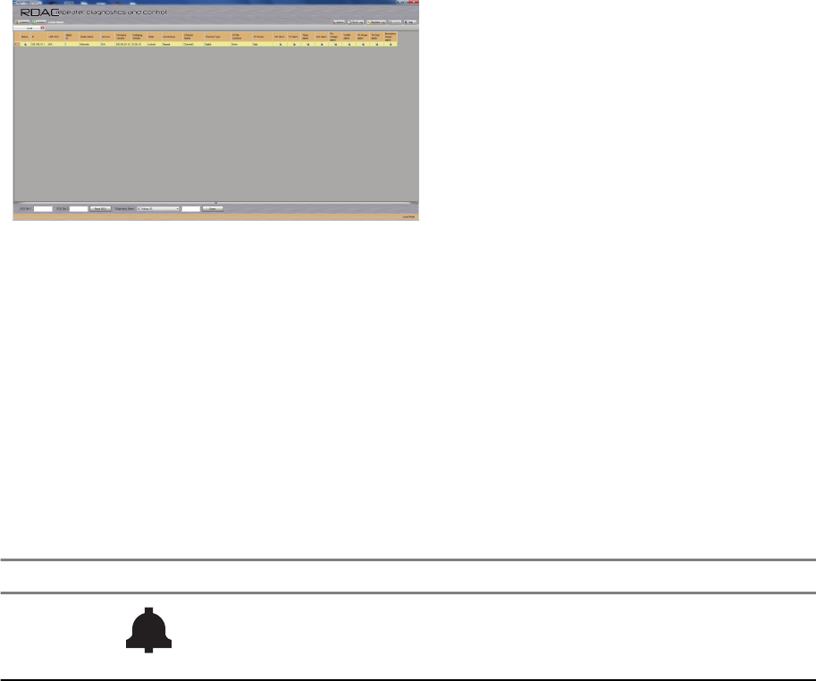
Basic Repeater Level Troubleshooting – RDAC and LEDs
Diagnostic tests are available for the Transceiver. If a problem occurs during station operation, it is
logged as an alarm that is read with the Repeater Diagnostic and Control application (RDAC). See
Figure 7: RDAC Diagnostic Screen on page 40 for the RDAC diagnostic screen.
Figure 7: RDAC Diagnostic Screen
The station operator then evaluates the problem locally or remotely, as the station maintains an Alarm
Log with the name of the alarm that has failed since the last power up. Through the RDAC application’s
Alarm Log, the alarm messages aid in identifying the FRU that failed along with the fault condition.
After booting up the repeater, the three LEDs (Power/ Status, Network, and Reference LEDs) flash in
unison.
The general status and condition of the SLR 1000 Repeater can be obtained by observing the three
LED indicators on the front panel. Table 9: SLR 1000 Repeater Front Panel LED Indicators on page
40 shows the LED symbols and their meaning, while Table 10: SLR 1000 Front Panel LED Definitions
on page 41 identifies the information conveyed through the LED indicators.
Table 9: SLR 1000 Repeater Front Panel LED Indicators
LED Definition
Status
Table continued…
MN003557A01-AA
Chapter 1: SLR 1000 Repeater
40 Send Feedback
Preliminary FCC Filing
LED Definition
Ethernet Link/ Network Connectivity
Reference
Table 10: SLR 1000 Front Panel LED Definitions
LED Function
Name
LED Col-
or
LED State Status Indication
Power/Status Off Off Off
Green Solid Operating Normally, with DC power
Red Flashing Repeater is Disabled (by customer)
Solid Not Operational – Major Alarm
Amber Flashing* Check Alarm Log – Alarm occurred and cleared
but remains latched (configurable)
Solid Repeater Operational – Minor Alarm
Ethernet/ Network
Connectivity
Off Off No Ethernet connection
Green Solid Connectivity/ Linked
Flashing Attempting to connect to the system
Reference Off Off For future use
NOTICE: All LEDs flashing in unison indicate the repeater is booting up.
The RDAC application will be needed when the Status LED is red (solid or flashing). This status
indicates a minor or major alarm. The RDAC application is used to identify the specific alarm
and probable diagnosis to aid in identifying the FRU at fault.
(*) Not supported in initial release.
MN003557A01-AA
Chapter 1: SLR 1000 Repeater
Send Feedback 41
Preliminary FCC Filing
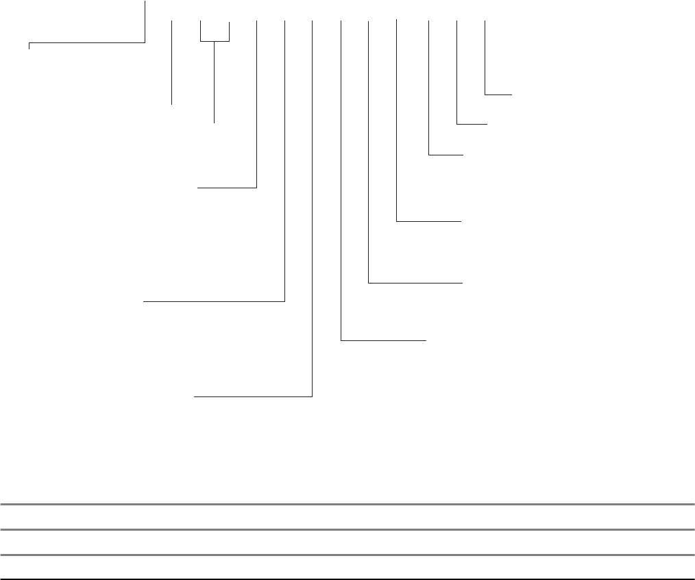
1.8
SLR 1000 Repeater Model Numbering Scheme
Figure 8: SLR 1000 Repeater Model Numbering Scheme
Model No.Example : AA R 1 1 S D G A N Q 1 A N
Position: 1 2 3 4 5 6 7 8 9 10 11 12
Unique Variation
N: Standard Package
Version Letter
Package
1: Standard Bracket
2: Pole Mount
Preselector
Q: Standard Model (none)
Add-on Boards
N: None
P: Expansion Board
Performance
A: Standard
Power Level
D: 1–10 Watt
Band
S: 400–527 MHz
Cover
G: LED Indicators
R: Repeater
AZ: Asia
LA: Latin America
AA: North America
MD: Europe
MOTOTRBO Repeater Model:
11: SLR 1000
1.9
UHF High Power Model Chart
SLR 1000, UHF, 400 – 527 MHz
Model Description
AAR11SDGANQ1AN 400–512 MHz, 1 – 10 W, SLR 1000 Repeater
MN003557A01-AA
Chapter 1: SLR 1000 Repeater
42 Send Feedback
Preliminary FCC Filing

Chapter 2
SLR 1000 Satellite Receiver
2.1
Description
The main purpose of the Satellite Receiver is to eliminate "dead zones" in a communications system
by improving the "talk-in" coverage on a particular receive frequency when used in a receiver voting
system.
The Motorola Solutions SLR 1000 Repeater is not offered as an exclusive Satellite Receiver only
model, rather the repeater can be configured through Radio Management to operate as a Satellite
Receiver in a receive only mode of operation. As such, the context of this chapter assumes that the
repeater is configured as a Satellite Receiver.
NOTICE: Configuring the repeater as a Satellite Receiver is only compatible with the
MOTOTRBO Digital Voting feature.
2.2
Operating Features
The features are identical to the SLR 1000 Repeater, with the exception that all transmitter related
functions are not applicable. See SLR 1000 Repeater on page 33 for more details.
2.3
Frequency Ranges
The supported frequency ranges are identical to the SLR 1000 Repeater’s receive frequency ranges.
See SLR 1000 Repeater on page 33 for more details.
2.4
Specifications
The specifications are identical to the SLR 1000 Repeater, with the exception that all transmitter
related specifications are not applicable. See SLR 1000 Repeater on page 33 for more details.
2.5
Configuration
Other than setting the general personality configurations, set the Operation Mode parameter under
the General Settings menu in Radio Management to Digital Satellite Receiver. See the following
figure.
MN003557A01-AA
SLR 1000 Satellite Receiver
Send Feedback 43
Preliminary FCC Filing
Figure 9: Operation Mode Configuration for Satellite Receiver Functionality
2.6
Basic Station Level Troubleshooting – RDAC and LEDs
The troubleshooting procedures are similar to the SLR 1000 Repeater with regards to the control,
transmitter, and receiver sub-systems. See SLR 1000 Repeater on page 33 for more details.
NOTICE: When configured for receiver only operation, the repeater does not support any
transmitter sub-system functions. As such, disregard all references to the transmitter section in
SLR 1000 Repeater on page 33. This includes any transmitter related topics in the RDAC and
the front panel LEDs.
2.7
Model Chart
The model chart is identical to the SLR 1000 Repeater. See UHF High Power Model Chart on page 42
for more details.
MN003557A01-AA
Chapter 2: SLR 1000 Satellite Receiver
44 Send Feedback
Preliminary FCC Filing

Chapter 3
SLR 1000 Transceiver Board
3.1
Description
The Transceiver board is described in this section. A general description, identification of inputs and
outputs, and functional theory of operation are provided. The information provided is sufficient to give
service personnel a functional understanding of the module, allowing maintenance and troubleshooting
to the module level.
3.1.1
General Description
The Transceiver board provides the receiver, transmitter, and station control functionality for the
repeater. Additionally the external connections to the station are connected directly to the transceiver
board.
3.1.2
Input and Output Connections
Figure 10: SLR 1000 Repeater Transceiver Board Connector Locations on page 45 shows the
Transceiver board input and output external connections.
Figure 10: SLR 1000 Repeater Transceiver Board Connector Locations
Table 11: SLR 1000 Repeater Front View (without top Cover) Callout Legend
Label Description
1 Transmitter RF (Tx) Output
2 Pressure Equalizer Vent
3 Receiver RF (Rx) Output
4 Transmitter RF (Tx) Input
5 Jumper Connection to enable external on/off function
6 Bonding Ground Connection
7 DC Power Inlet
8 Aux/Accessory Port
9 Ethernet Port
10 USB Port Programming Interface
11 Header Connection for optional antenna switch
12 Option Dependent 1 and 2
13 Expansion Board Connection (for future use)
14 Receiver RF (Rx) Input
15 Front Panel Flex Connector
MN003557A01-AA
SLR 1000 Transceiver Board
Send Feedback 45
Preliminary FCC Filing

3.1.3
Frequency Bands
The Transceiver board covers the following bands with unique models:
•400 – 527 MHz
3.2
Receiver Subsystem
The Transceiver board includes the receiver circuitry for the station. A cable connects the board
connector to an N-type connector on the upper left hand side of the repeater.
See Figure 10: SLR 1000 Repeater Transceiver Board Connector Locations on page 45 for the
location of this connector. The receiver section performs highly-selective bandpass filtering and dual
down-conversion of the desired RF signal. A custom Receiver IC then performs an analog-to-digital
conversion of the desired received signal and outputs the digitized signal to the controller section via a
serial synchronous interface. Included in the receiver section is:
Frequency Synthesizer Circuitry
Consists of a phase-locked loop and Voltage-Controlled Oscillator (VCO), generates the first LO
injection signal.
Varactor-tuned Preselector Filter(s)
Provides bandpass filtering of the station Receiver RF input.
Receiver Front End Circuitry
Performs filtering, amplification, and the first down conversion of the Receiver RF signal.
Receiver-specific piece of transceiver IC Circuitry
Consists of receiver-specific parts of a transceiver IC which performs the second down conversion,
filtering, amplification, and analog-to-digital conversion of the receive signal.
Analog to Digital Converter (ADC) Circuitry
Converts analog Receiver status signals to digital format for transfer to the controller circuitry
located on the Transceiver board.
3.2.1
Specifications
Table 12: Specifications of Receiver Subsystem
Parameter Specifications
UHF
Frequency Bands 400 – 527 MHz
Selectivity 25 kHz/ 12.5 kHz (TIA603D) 75 dB/ 50 dB
Selectivity 25 kHz/ 12.5 kHz (TIA603) 75 dB/ 65 dB
Selectivity 25 kHz/ 12.5 kHz (ETSI) 70 dB/ 63 dB
Sensitivity (12 dB SINAD) 0.3 uV
Sensitivity (5% BER) 0.3 uV
Intermodulation Rejection (TIA603D) 80 dB
Intermodulation Rejection (ETSI) 70 dB
Spurious Rejection (TIA603D) 85 dB
Table continued…
MN003557A01-AA
Chapter 3: SLR 1000 Transceiver Board
46 Send Feedback
Preliminary FCC Filing

Parameter Specifications
UHF
Spurious Rejection (ETSI) 75 dB
Audio Distortion <3%
FM Hum and Noise 25 kHz/ 12.5 kHz 50 dB/ 45 dB
3.3
Transmitter Subsystem
The Transmitter subsystem on the Transceiver board provides the transmitter functions for the station.
The Transmitter subsystem interfaces directly with the controller section, which provides control signals
and monitoring, and routes transmit data to the Exciter.
The RF carrier is generated by a frequency synthesizer consisting of synthesizer circuitry and Voltage-
Controlled Oscillator (VCO) circuitry. Exciter circuit control signals, monitoring, and audio processing
are handled by the controller section of the transceiver board. Included in the transmitter subsystem
are:
Frequency Synthesizer Circuitry
Consists of a phase-locked loop and Voltage-Controlled Oscillator (VCO), generates a modulated
RF signal at the transmitter carrier frequency.
RF Isolation Switch
Allows the controller section to turn on/off the Exciter RF input signal which greatly reduces signal
leakage when the transmitter is de-keyed.
Analog to Digital Converter (ADC) Circuitry
Converts the analog transmitter status signals to the digital format for transfer, upon request, to the
controller section of the Transceiver board.
3.3.1
Specifications
Table 13: Specifications of Transmitter Exciter Subsystem
Parameter Specifications
UHF
Frequency Range 400 – 527 MHz
Electronic Bandwidth Full Bandwidth
Output Power 10 W
Harmonics -76 dBc
3.4
Station Control Subsystem
The Station Control Subsystem is described in this section. A general description, identification of
controls, indicators, and inputs/outputs, a functional block diagram, and functional theory of operation
are provided.
The Controller circuitry performs the digital signal processing, data formatting and audio routing for the
station and provides the external interfaces to the rest of the site.
The Controller section consists of seven main ICs. These are:
MN003557A01-AA
Chapter 3: SLR 1000 Transceiver Board
Send Feedback 47
Preliminary FCC Filing
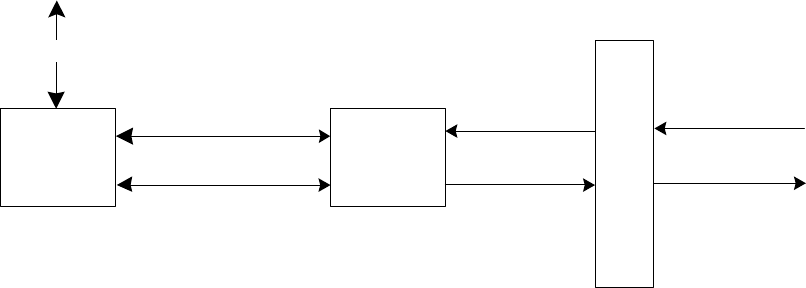
• Texas Instrument DM8148 Host/DSP Processor
•EMMC Flash memory
• DDR3 memory
• Texas Instruments Power Management IC
• NOR Flash
• TI AIC3204 Codec
General controller functionality includes:
• Data and Control interface to the transceiver ICs
• Audio interface with CODEC IC
• UART interface to expansion board
• Intermodule communication (SPI, I2C)
• Ethernet port
• USB Device port
• External physical interfaces (connectors, LEDs, external references etc.)
• Station Reference Control
3.4.1
Audio
The analog audio stages are used exclusively for external accessories connected through the bottom
RJ-45 accessory connector.
The critical components of the audio circuit are the TI DM8148 processor and a Texas Instruments
AIC3204 dual channel audio codecs. Figure 11: SLR 1000 Repeater Audio Block Diagram on page
48 details the specific interconnects between the critical components.
Figure 11: SLR 1000 Repeater Audio Block Diagram
TI DM8148
(DSP Core)
TI AIC3204
Audio
Codec
Accessory Connector
I²C (2)
Audio SSI (4) TX Audio (Pin 1)
RX Audio (Pin 7)
RFIC SSI (4)
RX Audio
The repeater digital audio is handled primarily by the DM8148 processor. The TX RFIC generates a
24.576 MHz master clock (MCLK) that the DM8148 uses to drive its McASP SSI interface for the audio
codecs. The bulk of the audio processing is done in the DaVinci’s DSP core. The audio codecs contain
DACs and ADCs and handle the conversion of the digital audio to analog audio and vice versa.
There is one TX audio line routed in from the rear accessory connector. This is TX Audio 1 (Pin 1, used
for analog and slot 1 digital).
MN003557A01-AA
Chapter 3: SLR 1000 Transceiver Board
48 Send Feedback
Preliminary FCC Filing
For the RX outputs, there is only 1 which is connected to the accessory connector. RX Audio 1 on
pin 7 (to be used for analog and slot 1 digital).
3.5
Station Control Interface
This section describes the different types of connectors and connections to the station control.
3.5.1
Bottom Panel Connections
See Ethernet on page 54 for details.
3.5.2
Expansion Board Interface Connector
The expansion board interface utilizes a 30-pin vertical LIF connector. The location is detailed in Figure
10: SLR 1000 Repeater Transceiver Board Connector Locations on page 45. Table 11: SLR 1000
Repeater Front View (without top Cover) Callout Legend on page 45 shows the pin number locations.
MN003557A01-AA
Chapter 3: SLR 1000 Transceiver Board
Send Feedback 49
Preliminary FCC Filing
This page intentionally left blank.
Preliminary FCC Filing

Chapter 4
SLR 1000 Front Panel
4.1
Description
The Front Panel board user interface includes three LED indicators. The board is connected to the
modem interface through a flex cable. The LED indicators inform the user of the state of the repeater.
The LED indications are transferred to the front panel through a serial peripheral interface.
MN003557A01-AA
SLR 1000 Front Panel
Send Feedback 51
Preliminary FCC Filing
This page intentionally left blank.
Preliminary FCC Filing

Chapter 5
SLR 1000 Bottom Panel
5.1
Description
The Bottom Panel interface provides the electrical interconnection interface between the SLR 1000
Repeater and the end user’s system. This includes the connectors necessary to program/configure the
repeater, as well as interface the repeater to the power system, system controllers, LANs, and other
communications and maintenance equipment. This section provides a general description,
identification of inputs/ outputs and how the inputs are connected and sealed, and a pin-out listing for
all connectors, including information on signal names, functions, and levels.
5.1.1
General Description
Figure 12: SLR 1000 Repeater Bottom Panel Connector Names and Locations on page 53 shows
the various interface connector locations. Table 14: SLR 1000 Repeater Connector Types and Primary
Functions on page 53 lists the connector types as well as its primary function.
Figure 12: SLR 1000 Repeater Bottom Panel Connector Names and Locations
Table 14: SLR 1000 Repeater Connector Types and Primary Functions
Location Connector Type Function(s)
1 N-Type – Fe-
male
Transmitter RF (Tx)
2 M6 TORX Screw Bonding Ground Connection
3 2.1 X 5.5 OD
Barrel Connector
DC Power Inlet
4 RJ-45 – Aux/
Accessory
Rx Audio, Tx Audio, PTT, 1 PPS, and GPIO
5 RJ-45 – Ethernet Network
6 Type B USB
Socket
Programming Interface
7 Option Depend-
ent
Option Dependent 1 and 2
8 N-Type – Fe-
male
Receiver RF (Rx)
5.2
Bottom Panel Interfaces
This section describes the different bottom panel interfaces that are available in the repeater.
MN003557A01-AA
SLR 1000 Bottom Panel
Send Feedback 53
Preliminary FCC Filing

5.2.1
DC Power Inlet
The DC power inlet connector is a 2.1 X 5.5 Barrel type coaxial power connector receptacle panel.
Figure 13: DC Power Inlet Connector on page 54 shows the location of the pins and Table 15: DC
Power Inlet Connector Callout Legend on page 54 lists the functional characteristics of the
connector’s pins.
Figure 13: DC Power Inlet Connector
Table 15: DC Power Inlet Connector Callout Legend
Location Type Signal Characteristics
Inner 12 V 10.8 – 15.6 VDC
4 A (max)
Outer Ground
5.2.2
USB
Type B socket (Device Connection) that supports the USB 2.1 protocol standard. Figure 14: USB
Connector on page 54 shows the location of the pins and Table 16: USB Connector Callout Legend
on page 54 lists the functional characteristics of the connector’s pins.
Figure 14: USB Connector
Table 16: USB Connector Callout Legend
Location Pin Assignment Type Signal Characteristics
1 VBUS
USB Physical
Layer
+5 VDC
2 D- 3.6 V differential data
3 D+
4 GND Ground
5.2.3
Ethernet
Fully compliant with IEEE and 802.3 and 802.3u standards. Supports 10Base-T, 100Base-Tx rates, full
duplex, half duplex mode and flow control. Figure 15: Ethernet Connector on page 54 shows the
location of the pins and
Table 17: Ethernet Connector Callout Legend on page 54 lists the functional characteristics of the
connector’s pins.
Figure 15: Ethernet Connector
Table 17: Ethernet Connector Callout Legend
Location Pin Assignment Type Signal Characteristics
1 Ethernet Tx+
Ethernet
Physical Layer
5 V differential data
2 Ethernet Tx-
3 Ethernet Rx+
4 Unused N/A
Table continued…
MN003557A01-AA
Chapter 5: SLR 1000 Bottom Panel
54 Send Feedback
Preliminary FCC Filing

Location Pin Assignment Type Signal Characteristics
5 Unused N/A
6 Ethernet Rx- 5 V differential data
7 Unused N/A
8 Unused N/A
5.2.4
Auxiliary (Aux)/Accessory
This connection supports the analog interface to the SLR 1000 Repeater, which includes audio, station
control, station indicators, and provisions for timing used in various system implementations. Figure 16:
Auxiliary/Accessory Connector on page 55 shows the location of the pins and Table 18: Auxiliary/
Accessory Connector Callout Legend on page 55 lists the functional characteristics of the
connector’s pins.
Figure 16: Auxiliary/Accessory Connector
Table 18: Auxiliary/Accessory Connector Callout Legend
Location Pin Assignment Type Signal Characteristics
1 Tx Audio 1 Audio Transmit Audio – Nominal input level is 80 mVrms for 60%
deviation with scaling factor set to 100%. 600 Ω input im-
pedance.
2 GPIO 6 Digital Output Logic Low: 0.5 VDC max
Output Logic High: Open Collector with 10 k pull-up to 5 V
Input Logic Low: 0 – 0.8 VDC
Input Logic High: 3.0 – 14 VDC
3 Igition Sense
Control
Controls power to the unit if the internal jumper is config-
ured correctly.
4 Ground
5 GPIO 7 Analog
RSSI Out
Digital
or Ana-
log
Output Logic Low: 0.5 VDC max
Output Logic High: Open Collector with 10 k pull-up to 5 V
Input Logic Low: 0 – 0.8 VDC
Input Logic High: 3.0 – 14 VDC
Analog RSSI:
Typically 0.5 VDC for -120 dBm to 2.7 VDC for -60 dBm
carrier. Variation with carrier level at approximately 50 mV/
dBm.
6 GPIO 9/ *Analog
Input 1
Digital Output Logic Low: 0.5 VDC max
Output Logic High: Open Collector with 10 k pull-up to 5 V
Input Logic Low: 0 – 0.8 VDC
Input Logic High: 3.0 – 14 VDC
Analog: 0 – 5 VDC
Table continued…
MN003557A01-AA
Chapter 5: SLR 1000 Bottom Panel
Send Feedback 55
Preliminary FCC Filing

Location Pin Assignment Type Signal Characteristics
7 Rx Audio 1 Audio Receiver Audio – Nominal output level is 330 mVrms (into
a 50 k Ohm load) with a 60% deviation receive signal.
1000 Ω output impedance.
8 GPIO 4 Digital Output Logic Low: 0.5 VDC max
Output Logic High: Open Collector with 10 k pull-up to 5 V
Input Logic Low: 0 – 0.8 VDC
Input Logic High: 3.0 – 14 VDC
* = Currently not supported.
MN003557A01-AA
Chapter 5: SLR 1000 Bottom Panel
56 Send Feedback
Preliminary FCC Filing

Chapter 6
SLR 1000 Test Equipment And
Service Aids
6.1
Recommended Test Equipment
The list of equipment includes most of the standard test equipment required for servicing Motorola
Solutions SLR 1000 Repeaters.
Table 19: Recommended Test Equipment
Equipment Example Application
Service Monitor Aeroflex 3920 Digital Radio Test
Set or equivalent 1
http://www.aeroflex.com
Frequency/deviation meter, signal
generator, oscilloscope, RF power
meter for wide-range trouble-
shooting, and alignment.
Digital RMS Mul-
timeter
Fluke 179 or equivalent http://
www.aeroflex.com.
AC/DC voltage measurements.
6.2
Service Aids
Table 20: Service Aids on page 57 lists the service aids recommended for working on the SLR 1000
Repeater. While all of these items are available from Motorola Solutions, most are standard workshop
equipment items, and any equivalent item capable of the same performance may be substituted for the
item listed.
Table 20: Service Aids
Motorola Solutions
Part Number
Description Application
HSN1006_ Speaker Listen to audio
PMVN4130_ Customer Programming
Software on CD-ROM
Allows servicer to program repeater parameters,
tune and troubleshoot repeater.
30009477001 Standard Type "A" to
Type "B" USB Program-
ming cable
Connects the repeater front connector to a USB
port for radio programming and data applications.
PMKN4166_ Repeater Rear Accesso-
ry Test Cable
Connects the repeater’s rear connector to micro-
phone and speaker
GMMN4063_ Microphone To transmit audio
Table continued…
1Equivalency can be established with "all-in-one" service monitors and/or the individual functional
components of a service monitor (such as RF Signal Generator, RF Spectrum Analyzer, RF De-
viation Meter, RF Power Meter, and oscilloscope).
MN003557A01-AA
SLR 1000 Test Equipment And Service Aids
Send Feedback 57
Preliminary FCC Filing

Motorola Solutions
Part Number
Description Application
RLN4460_ Test Box Used to inject/ measure audio
CB000174A02 DB-25 to RJ-45 Adapter Used to connect the accessory test cable to the
RJ-45 accessory connector
MN003557A01-AA
Chapter 6: SLR 1000 Test Equipment And Service Aids
58 Send Feedback
Preliminary FCC Filing

Chapter 7
SLR 1000 Performance Check or
Testing
7.1
General
The SLR 1000 Repeater meets published specifications through the manufacturing process by utilizing
high-accuracy laboratory-quality test equipment. The recommended field service equipment
approaches the accuracy of the manufacturing equipment with few exceptions. This accuracy must be
maintained in compliance with the equipment manufacturer’s recommended calibration schedule.
NOTICE: Although these repeaters function in digital and analog modes, all testing is done in
analog mode. Digital Repeater tests can be performed using an Aeroflex 3900 Series Service
Monitor, if the DMR Digital Repeater Test Option is purchased. This auto testing could be
performed in lieu of the following Manual testing.
7.2
Transmitter Testing
CAUTION: The SLR 1000 Series Repeater needs to be taken out of service in order to carry
out performance testing procedures. Unless the repeater is already out of service, it is
recommended to perform the procedures during off-peak hours in order to minimize disruption
of service to the system subscribers.
7.2.1
Introduction
While most module faults can be detected by running the repeater diagnostics, the following procedure
provides a more traditional method of troubleshooting the transmitter circuitry.
This procedure allows the service technician to make minor adjustments and verify proper operation of
the repeater transmit circuitry.
In general, the transmitter circuitry is exercised by injecting and measuring signals using a Service
Monitor (or equivalent). Incorrect measurement values indicate a faulty module(s); measurement
values within the acceptable range verify proper operation the transceiver board and circuitry.
7.2.2
Test Equipment
The following test equipment are required to perform the procedure:
• Aeroflex 3920 Digital Radio Test Set (or equivalent)
• Microphone (GMMN4063_)
• Power Meter and Sensor
• Station Rear Accessory Test Cable
• Dummy Load (50 Ω, repeater wattage or higher)
• DB25/RJ-45 Adapter
MN003557A01-AA
SLR 1000 Performance Check or Testing
Send Feedback 59
Preliminary FCC Filing
7.2.3
Verifying Transmitter Circuitry
Procedure:
1Connect and set up test equipment as shown in Figure 17: Test Equipment Setup for Verifying
Transmitter Circuitry on page 61.
2Apply input power to the repeater.
3Press the PTT switch of the microphone.
4Measure output power by observing reading on an in-line wattmeter.
aIf the transmitter output is not at proper power (as set for a particular site), adjust the output
power as described in the Radio Management online help.
5If the transmitter output power is proper, set up the Service Monitor for spectrum analyzer
display.
aPress the PTT button and observe the display.
The display should show a single frequency carrier:
bIf the display shows multiple carriers evenly spaced about the carrier, suspect a faulty Exciter
module or PA module.
cIf the display shows a solid carrier but it is off frequency, suspect the following:
• Faulty transceiver board
• Faulty external 5/10 MHz reference source (if used)
dIf the display shows a single carrier moving erratically, suspect a faulty transceiver board.
6If display is proper, set up Aeroflex 3900 Series Communications System Analyzer to display
modulation.
aUsing the microphone, push the PTT button and speak into the microphone.
bVerify that the display shows an audio signal.
cIf the proper display is not obtained, suspect faulty transceiver board.
7Set the Aeroflex 3900 Series Communications System Analyzer for GEN/ MON MTR.
aPress the PTT button and speak loudly into the microphone to cause maximum deviation.
Display should read:
• 4.60 kHz maximum for a 25 kHz system
• 3.68 kHz maximum for a 20 kHz system
• 2.30 kHz maximum for a 12.5 kHz system
bIf the proper display is not obtained, suspect faulty transceiver board.
8This completes the Verifying Transmitter Circuitry test procedure. If all displays and
measurements are correct, the transmitter circuitry may be considered to be operating properly.
MN003557A01-AA
Chapter 7: SLR 1000 Performance Check or Testing
60 Send Feedback
Preliminary FCC Filing
Figure 17: Test Equipment Setup for Verifying Transmitter Circuitry
Tx
Dummy Load
Power Meter
Microphone
(GMMN4063)
(Step 5)
T/R
7.3
Receiver Testing
CAUTION:
Performing this procedure requires that the repeater be taken out of service. It is recommended
that, unless the SLR 1000 Series Repeater is already out of service, this procedure be
performed during
off-peak hours so as to minimize the disruption of service to the system subscribers.
If the repeater operates as a repeater, the transmit output from the repeater must be connected
to a dummy load to prevent over-the-air broadcast during Receiver testing.
7.3.1
Introduction
While most module faults can be detected by running the SLR 1000 Series Repeater diagnostics, the
following procedure provides a more traditional method of troubleshooting the Receiver circuitry.
This procedure allows the service technician to make minor adjustments and verify proper operation of
the receiver circuitry on the Transceiver Board.
In general, the Receiver circuitry is exercised by injecting and measuring signals using a Service
Monitor (or equivalent). Incorrect measurement values indicate a faulty module(s); measurement
values within the acceptable range verify proper operation of the receiver circuitry on the Transceiver
Board.
MN003557A01-AA
Chapter 7: SLR 1000 Performance Check or Testing
Send Feedback 61
Preliminary FCC Filing
7.3.2
Required Test Equipment
The following test equipment are required to perform the procedure:
•Aeroflex 3920 Digital Radio Test Set (or equivalent)
• Service Speaker (part no. HSN1006_)
• Station Rear Accessory Test Cable
• Dummy Load (50 Ω, repeater wattage or higher) required for repeaters only
• DB25/RJ-45 Adaptor
7.3.3
Verifying Receiver Circuitry
Procedure:
1Connect equipment as shown in Figure 18: Test Equipment Setup for Verifying Receiver
Circuitry on page 63.
2Set the service monitor to generate a 1.0 μV (-107 dBm) FM signal at the receiver frequency,
modulated by a 1 kHz tone at 3 kHz deviation for 25 /30 kHz channel spacing, or 1.5 kHz
deviation for 12.5 kHz channel spacing. The 1 kHz tone should be audible through the external
speaker. If no audio is heard, suspect the following:
• Faulty transceiver board
• Faulty service monitor-to-station RF cable
• Left panel to transceiver board cable unplugged
• Faulty left panel to transceiver board cable
3If audio is heard (the audio volume can be adjusted on the rear of the HSN1006), look at the
oscilloscope window on the Aeroflex 3920 (or a separate O-Scope).
aVerify that the audio level sine wave measures between 0.75 to 1.5 Vpp.
bIf not, connect to the tuner and increase the Rx audio level until this is achieved. If the level
cannot be obtained, suspect a faulty transceiver board.
4Move the BNC cable from the scope CH 1 input to the Audio 1 input.
5Change System Monitor injection signal level to the noted levels in Table 8: SLR 1000 Repeater
Specifications on page 37.
6Measure the receiver 12 dB SINAD sensitivity.
aIf the SINAD level is less than 12 dB, suspect a faulty transceiver board.
7This completes the Verifying Receiver Circuitry test procedure. If all displays and measurements
are correct, the receiver circuitry may be considered to be operating properly.
aRemove test equipment, restore the repeater to normal service, and (if applicable) return to
the troubleshooting flow chart to resume troubleshooting sequence.
MN003557A01-AA
Chapter 7: SLR 1000 Performance Check or Testing
62 Send Feedback
Preliminary FCC Filing
Figure 18: Test Equipment Setup for Verifying Receiver Circuitry
Rx Tx
Dummy Load
Power Supply
Service Speaker
(HSN1006_)
Test Box (RLN4460_)
MT B+
CH 1 GEN
MN003557A01-AA
Chapter 7: SLR 1000 Performance Check or Testing
Send Feedback 63
Preliminary FCC Filing
This page intentionally left blank.
Preliminary FCC Filing
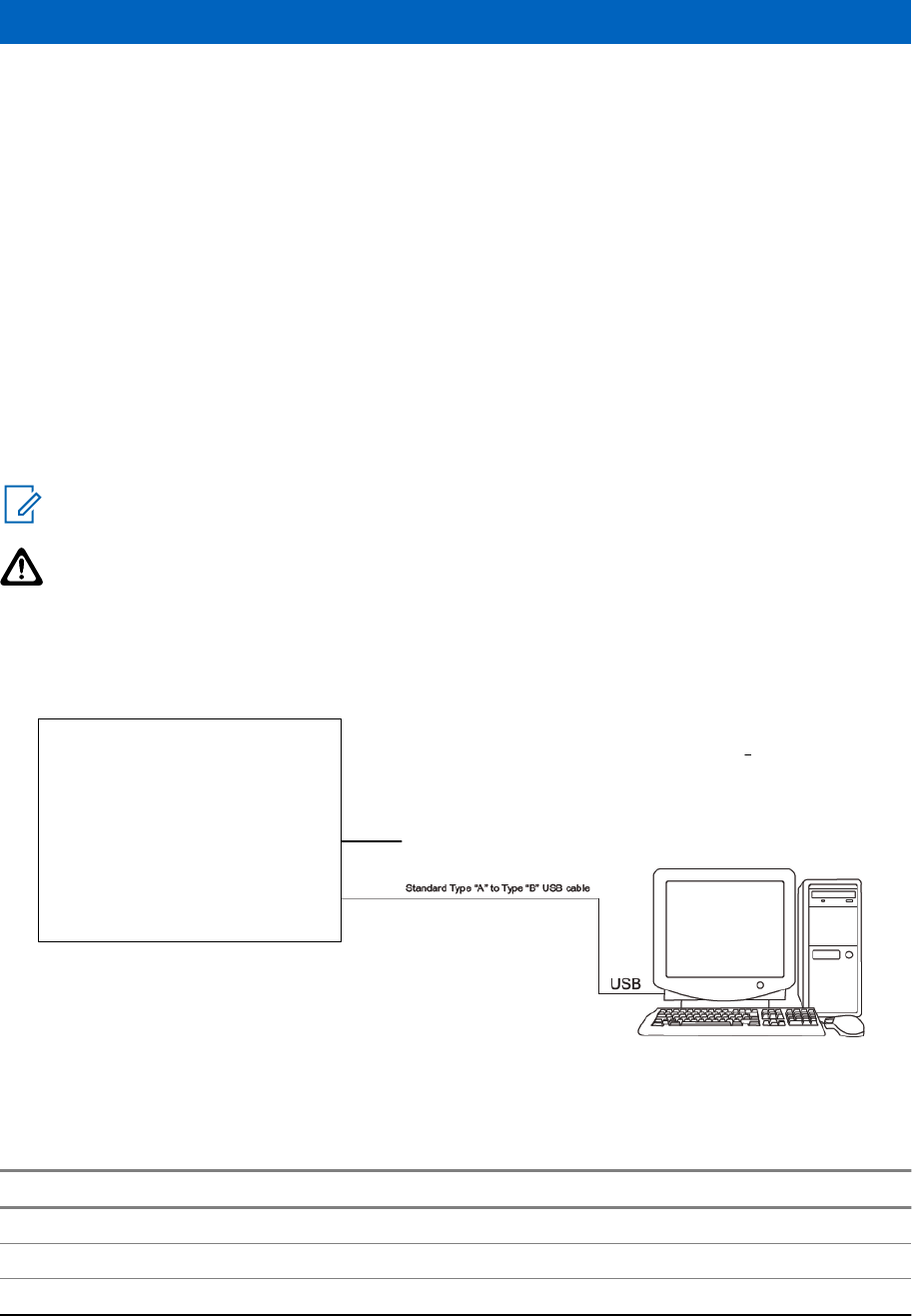
Chapter 8
SLR 1000 Programming and Tuning
8.1
Introduction
This chapter provides an overview of the MOTOTRBO Radio Management (RM) and the MOTOTRBO
Tuner application for use on Windows 7™, Windows 8™, or Windows 8.1™. These two MOTOTRBO
applications are used for the configuration and alignment of the SLR 1000 Repeater.
8.2
Radio Management Setup
The Radio Management setup, shown in Figure 19: Radio Management Setup on page 65 is used to
program the repeater. See Figure 20: Bottom View of SLR 1000 Repeater on page 65 for the actual
connectors on the front of the repeater.
NOTICE: See appropriate program on-line help files for the programming procedures.
CAUTION: Computer USB ports can be sensitive to Electronic Discharge. Employ proper ESD
practices (wrist strap, grounding, etc.) and do not touch exposed contacts on cables when
connected to a computer.
Figure 19: Radio Management Setup
Station
Bottom Panel
13.6 V DC
Figure 20: Bottom View of SLR 1000 Repeater
Table 21: Bottom View of the SLR 1000 Repeater Callout Legend
Label Description
1 USB Port Programming Interface
2 Ethernet Port
3 Aux/Accessory Port
Table continued…
MN003557A01-AA
SLR 1000 Programming and Tuning
Send Feedback 65
Preliminary FCC Filing

Label Description
4 DC Power Inlet
5 Bonding Ground Connection
8.3
Reference Oscillator Alignment
This feature is used to adjust the reference oscillator of the repeater. This alignment process should be
done as maintenance schedules and regulations require or if the Transceiver board FRU has been
replaced in the repeater.
8.3.1
Tuning the Reference Oscillator
Procedure:
1Connect the SLR 1000 Repeater's transmitter antenna port to the Communication Analyzer.
2Power the repeater from either an AC or DC source.
3Launch the Tuner application, and click Read to begin reading the repeaters tuning software
values.
4Under the TX menu in the tree view, select Ref Oscillator. See Figure 21: Tx Menu Tree (Ref.
Oscillator) on page 66
Figure 21: Tx Menu Tree (Ref. Oscillator)
5Configure the currently operating frequency into the Communications Analyzer.
6Click PTT Toggle to key up the repeater.
7Adjust the working softpot value until the frequency is within the performance specifications (+/-
40 Hz for UHF) from the frequency point.
8Click PTT Toggle to de-key the repeater.
9To save the tuned softpot value into the repeater codeplug, click Write.
8.4
Repeater Tuning Setup
A personal computer (PC), Windows™ operating system, and the MOTOTRBO Tuner application are
required to align the repeater. To perform the tuning procedures, the repeater must be connected to
the PC and test equipment setup as shown in Figure 22: SLR 1000 Repeater Tuning Equipment Setup
on page 67.
MN003557A01-AA
Chapter 8: SLR 1000 Programming and Tuning
66 Send Feedback
Preliminary FCC Filing
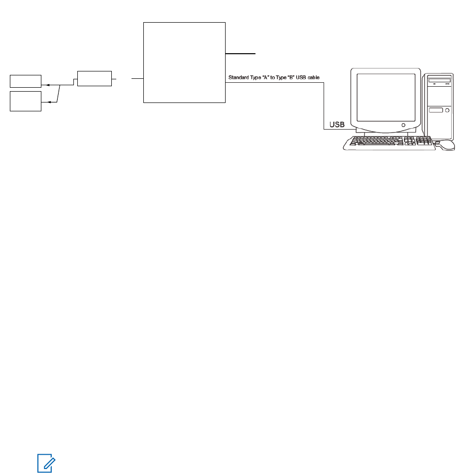
Figure 22: SLR 1000 Repeater Tuning Equipment Setup
Station
Bottom Panel
13.6 V DC
Tx Input
Port
Wattmeter 20 dB Pad
Service Monitor
or Counter
Transmit
8.5
Rx Audio Level Set
The procedure outlined in this section is used to set the receive output audio level from the repeater for
a given RF deviation of the received RF signal. Perform this procedure any time the Rx audio level
needs adjustment.
8.5.1
Tuning the Rx Audio Level Set
Procedure:
1Connect the repeater’s receiver antenna port to the Communication Analyzer.
2Power the repeater from either an AC or DC source.
3Launch the Tuner application and click Read to read the softpot values.
4Under the RX menu in the tree view, select Rx Rated Volume. (See Figure 23: RX Menu tree
(Rx Rated Volume) on page 67).
Figure 23: RX Menu tree (Rx Rated Volume)
5Set the Communication Analyzer to output a -47 dBm RF signal modulated with a 1 kHz tone at
60% of full deviation on the tuning frequency. The tuning frequency is the value displayed on the
Tuner GUI under the heading of “Frequency Points”.
NOTICE: The Tuner aligns this parameter in a 12.5 kHz channel spacing, so 60% is 1.5
kHz of deviation. If Radio Management (RM) is set for 25 kHz operation, the repeater
automatically scales the deviation by a factor of two when it is outside the Tuner
environment.
Programmed TPL and DPL squelch requirements are automatically disabled for the
tuning frequency while in the Tuner environment.
6Adjust the softpot value until the desired receive audio level is achieved at pin #7 (in reference to
ground) on the Aux connector. The ground connection provided by the Aux connector is pin 4.
MN003557A01-AA
Chapter 8: SLR 1000 Programming and Tuning
Send Feedback 67
Preliminary FCC Filing
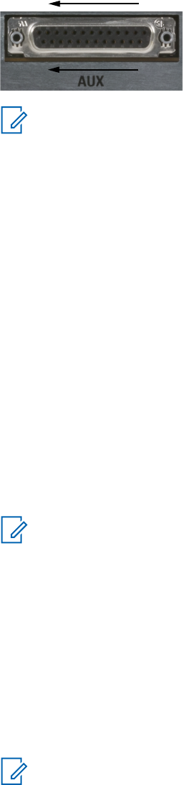
Figure 24: Auxiliary Connector
14
25
1
13
NOTICE: Optimally, it is recommended to load pin #7 with application loading used
during normal operation of the repeater.
7To save the new tuned softpot value into the repeater’s codeplug, click Write.
8.6
Tx Audio Level Set
The procedure outlined in this section is used to allow adjustment of the transmitter audio level the
repeater is expecting at its Aux connector. Adjusting this level set has the effect of increasing or
decreasing RF signal deviation for a given transmit audio level. Perform this procedure any time the
transmitter audio level needs adjustment.
8.6.1
Tuning the Tx Audio Level Set
Procedure:
1Connect the repeater’s transmitter antenna port to the Communication Analyzer.
2Power the repeater from a DC source.
3Apply a 1 kHz signal at the desired input level to pin #1 (in reference to ground) on the Aux
connector. The group connection provided by the Aux connector is pin-4. See Figure 24:
Auxiliary Connector on page 68
NOTICE: Optimally, it is recommended to load pin #1 with the application source
impedance used during normal operation of the repeater.
4Launch the Tuner application and click Read to read the softpot values.
5Under the TX menu in the tree view, select Tx Audio Level. (SeeFigure 25: Tx Menu Tree (Tx
Rated Volume) on page 68 ).
Figure 25: Tx Menu Tree (Tx Rated Volume)
6Enter the tuning frequency into the Communication Analyzer (the value displayed on the Tuner
GUI under the heading of Frequency Points.
7Click PTT Toggle to key up the repeater.
8Adjust the softpot value until the desired receive audio level is achieved at pin #7 (in reference to
ground) on the Aux connector. The ground connection provided by the Aux connector is pin 4.
NOTICE: The Tuner aligns this parameter in a 12.5 kHz channel spacing, so 60% is 1.5
kHz of deviation. If Radio Management (RM) is set for 25 kHz operation, the repeater
automatically scales the deviation by a factor of two when it is outside the Tuner
application.
9Click PTT Toggle to de-key the repeater.
10 To save the new tuned softpot value into the repeater’s codeplug, click Write.
MN003557A01-AA
Chapter 8: SLR 1000 Programming and Tuning
68 Send Feedback
Preliminary FCC Filing

8.7
Modulation Limit Alignment
This feature is to set the modulation limit of the SLR 1000 Repeater.
NOTICE: A modulation limit alignment is not needed if the repeater is used in repeat mode.
This is always the case when the repeater is in digital mode.
8.7.1
Tuning the Modulation Limit (with no Tx Data and no PL)
Procedure:
1Connect the repeater's antenna port to the attenuation pad, if necessary, before connecting to
the Communication Analyzer.
2Power the repeater from a DC source.
3Apply a 1 kHz signal at 1.2 Vrms to Pin 1 of the Aux connector.
•Signal ground is Pin 9 of the Aux connector.
4Launch the Tuner application.
5To read the softpot values, click Read.
6Under the TX menu in the tree view, select Modulation Limit.
Figure 26: TX Menu Tree (Tuning Procedure with No Tx Data)
7Enter the tuning frequency into the Communication Analyzer (the value displayed on the Tuner
application).
8To key up the repeater, click PTT Toggle.
9Adjust the softpot value until the maximum deviation is 92% of the rated system deviation
(RSD). This is tested in a 12.5 kHz channel spacing, so 92% of 2.5 kHz is 2.3 kHz.
10 Set the modulation limit to 92% so that any additional deviation incurred by the transmitter VCOs
over temperature is compensated for.
Channel Spacing
(kHz)
RSD (kHz) 92% of RSD (kHz) Tolerance (Hz)
12.5 2.5 2.3 +0/ -50
11 To de-key the repeater, click PTT Toggle
12 To save the new tuned softpot value into the repeater's codeplug, click Write.
8.7.2
Verifiying the Modulation Limit (with no Tx Data and no PL)
Procedure:
1Connect the repeater's antenna port to the attenuation pad, if necessary, before connecting to
the Communication Analyzer.
2Power the repeater from a DC source.
3In Radio Management (RM), program the repeater with any frequency within the specified range
of the repeater under test, and set the repeater for low power and disable the repeat path.
4Apply a 1 kHz signal at 1.2 Vrms to Pin 1 of the Aux connector.
MN003557A01-AA
Chapter 8: SLR 1000 Programming and Tuning
Send Feedback 69
Preliminary FCC Filing

• Signal ground is Pin 4 of the Aux connector.
5Key up the repeater and measure the deviation
•Key the repeater by grounding Pin 2 of the Aux connector.
NOTICE: RM must have Pin 2 configured as an active low with the PTT function.
6De-key the repeater.
The deviation shall meet the limits shown in the following table.
Channel Spacing
(kHz)
Relative Standard Deviation (RSD)
(kHz)
92% of RS
(kHz)
Tolerance
(Hz)
12.5 2.5 2.3 +0/-50
20.0 4.0 3.68 +0/-80
25.0 5.0 4.6 +0/-100
NOTICE:
•The repeater is factory-tuned in accordance to this procedure and specification.
• Verification is performed outside of the Tuner application, such as in normal mode.
MN003557A01-AA
Chapter 8: SLR 1000 Programming and Tuning
70 Send Feedback
Preliminary FCC Filing

Chapter 9
SLR 1000 Maintenance and
Disassembly/Reassembly
9.1
Introduction
This chapter provides details about the following:
•Routine maintenance
• Preventive maintenance (inspection and cleaning)
• Safe handling of CMOS and LDMOS devices
• Disassembly and reassembly of the repeater
• Repair procedures and techniques.
9.2
Routine Maintenance
NOTICE: Clean the repeater with a soft dry cloth while in service.
The SLR 1000 Repeater and ancillary equipment have been designed with state-of-the-art technology
and operate under software control, thus requiring minimal routine maintenance. Virtually all repeater
operating parameters are monitored and self-corrected by the Transceiver and the firmware it runs,
which makes adjustments and tuning virtually unnecessary.
Provided that the equipment is installed in an area which meets the specified environmental
requirements, the only routine maintenance task required is the calibration of the repeater reference
oscillator circuit.
MN003557A01-AA
SLR 1000 Maintenance and Disassembly/Reassembly
Send Feedback 71
Preliminary FCC Filing
9.3
Preventive Maintenance
Periodic visual inspection and cleaning is recommended.
9.3.1
Inspection
Check that the external surfaces of the SLR 1000 Series Repeater are clean, and that all external
controls and connections are in order. It is not recommended to inspect the interior electronic circuitry.
9.3.2
Cleaning Procedures
The following procedures describe the recommended cleaning agents and the methods to be used
when cleaning the external and internal surfaces of the SLR 1000 Repeater. External surfaces include
the top cover and repeater enclosure.
Periodically clean smudges and grime from exterior enclosure. Use a soft, non-abrasive cloth
moistened in a 0.5% solution of mild dishwashing detergent and water solution. Rinse the surface
using a second cloth moistened in clean water, and clean any dirt or debris from the heatsink fins.
The only factory recommended liquid for cleaning the printed circuit boards and their components is
isopropyl alcohol (100% by volume).
9.4
Safe Handling of CMOS and LDMOS Devices
Complementary metal-oxide semiconductor (CMOS) and laterally diffused metal-oxide semiconductor
(LDMOS) devices are used in this family of stations, and are susceptible to damage by electrostatic or
high voltage charges. Damage can be latent, resulting in failures occurring weeks or months later.
Therefore, special precautions must be taken to prevent device damage during disassembly,
troubleshooting, and repair.
Handling precautions are mandatory for CMOS/LDMOS circuits and are especially important in low
humidity conditions.
DO NOT attempt to disassemble the repeater without first referring to the following CAUTION
statement.
MN003557A01-AA
Chapter 9: SLR 1000 Maintenance and Disassembly/Reassembly
72 Send Feedback
Preliminary FCC Filing

CAUTION: This repeater contains static-sensitive devices. Do not open the repeater unless you
are properly grounded. Take the following precautions when working on this unit:
•Store and transport all CMOS/LDMOS devices in conductive material so that all exposed
leads are shorted together. Do not insert CMOS/LDMOS devices into conventional plastic
"snow" trays used for storage and transportation of other semiconductor devices.
• Ground the working surface of the service bench to protect the CMOS/LDMOS device. We
recommend using the Motorola Solutions Static Protection Assembly (part number
0180386A82), which includes a wrist strap, two ground cords, a table mat, and a floor mat,
ESD shoes and an ESD chair.
• Wear a conductive wrist strap in series with a 100k resistor to ground. (Replacement wrist
straps that connect to the bench top covering are Motorola Solutions part number
4280385A59).
• Do not wear nylon clothing while handling CMOS/LDMOS devices.
• Do not insert or remove CMOS/LDMOS devices with power applied. Check all power
supplies used for testing CMOS/LDMOS devices to be certain that there are no voltage
transients present.
• When straightening CMOS/LDMOS pins, provide ground straps for the apparatus used.
• When soldering, use a grounded soldering iron.
• If at all possible, handle CMOS/LDMOS devices by the package and not by the leads. Prior
to touching the unit, touch an electrical ground to remove any static charge that you may
have accumulated. The package and substrate may be electrically common. If so, the
reaction of a discharge to the case would cause the same damage as touching the leads.
9.5
Installing a Duplexer
Perform this procedure to install a duplexer into the SLR 1000 Repeater.
Prerequisites: Obtain the following:
• Duplexer kit
• Four M3 screws (obtained from the repeater package)
• T10 bit screwdriver
When and where to use:
Install a duplexer when transmitting and receiving using one antenna.
Procedure:
1Turn off power to the repeater.
2Disassemble the repeater, as follows:
aTurn the repeater over and remove the four M4 screws using a T10 bit.
bHold the cover onto the chassis and carefully turn the repeater over.
cSlowly remove the top cover, making sure not to damage the front panel flex cable.
3Disconnect the following cables. See Figure 27: SLR 1000 Repeater Front View (without top
cover) on page 74.
aDisconnect the front panel flex cable from the front panel display board.
bCut the tie wrap that secures the Tx and Rx cables.
cDisconnect the Rx cable from the Rx output port by gently pulling up.
dDisconnect the Tx cable from the Tx output port by gently pulling up.
MN003557A01-AA
Chapter 9: SLR 1000 Maintenance and Disassembly/Reassembly
Send Feedback 73
Preliminary FCC Filing

eRemove the Tx cable by either cutting the cable from the Tx input port or tie wrapping the
cable.
CAUTION: The Tx cable must not touch any components on the board.
Figure 27: SLR 1000 Repeater Front View (without top cover)
Table 22: SLR 1000 Repeater Front View (without top Cover) Callout Legend
Label Description
1 Transmitter RF (Tx) Output
2 Receiver RF (Rx) Output
3 Transmitter RF (Tx) Input
4 Receiver RF (Rx) Input
5 Front Panel Flex Connector
4Install the duplexer into the repeater, as follows:
aLay the front panel flex cable down across the board.
bPlace the duplexer into the chassis and align the screw openings, as shown in Figure 28:
SLR 1000 Repeater Front View (without top cover) with a Duplexer on page 74
cInsert the duplexer antenna port through the Rx input opening in the chassis.
dReinstall the lockwasher and nut onto the antenna port. Torque to 20 in./lbs.
eInsert the low passport cable into the Tx output port.
fPlace the high passport cable underneath the duplexer and insert into the Rx output port.
gSecure the duplexer to the chassis with the four M3 screws using a T10 bit. Torque to 10 in./
lbs.
hReattach the front panel flex cable to the front panel display board, making sure not to bend
the cable.
The cable stops at the black line.
iPlace the top cover back onto the chassis, making sure not to pinch any cables.
jHold the cover onto the chassis and carefully turn the repeater over.
kReinstall the four M4 screws using a T10 bit. Torque to 20 in./lbs.
5Restore power to the repeater.
Figure 28: SLR 1000 Repeater Front View (without top cover) with a Duplexer
Table 23: SLR 1000 Repeater Front View (without top Cover) with a Duplexer Callout Legend
Label Description
1 Transmitter RF (Tx) Output
2 Duplexer
3 Receiver RF (Rx) Output
4 Transmitter RF (Tx) Input
5 Receiver RF (Rx) Input
Table continued…
MN003557A01-AA
Chapter 9: SLR 1000 Maintenance and Disassembly/Reassembly
74 Send Feedback
Preliminary FCC Filing

Label Description
6 Front Panel Flex Connector
9.6
Installing a High-Speed Solid-State Antenna Switch
Perform this procedure to install a high-speed, solid-state antenna switch into the SLR 1000 Repeater.
Prerequisites: Obtain the following:
•Contents of the antenna switch package. Consists of:
- One antenna switch
- Two M3 screws
- Two MCX cables
- One power cable
• T10 bit screwdriver
When and where to use:
This switch is required for a single antenna, single frequency operation. With the use of the antenna
switch, you can configure the repeater as a Direct Mode Range Extender for use with the Extended
Range Direct Mode feature. Two separate antennas may be used when enough isolation is maintained
between them. The switch can also be used in traditional simplex operation.
Procedure:
1Turn off power to the repeater.
2Disassemble the repeater, as follows:
aTurn the repeater over and remove the four M4 screws using a T10 bit.
bHold the cover onto the chassis and carefully turn the repeater over.
cSlowly remove the top cover, making sure not to damage the front panel flex cable.
3Disconnect the following cables. See Figure 29: SLR 1000 Repeater Front View (without top
cover) on page 75.
aDisconnect the front panel flex cable from the front panel display board.
bCut the tie wrap that secures the Tx and Rx cables.
cDisconnect the Rx cable from the Rx output port by gently pulling up.
dDisconnect the Tx cable from the Tx output port by gently pulling up.
eRemove the Tx cable by either cutting the cable from the Tx input port or tie wrapping the
cable.
CAUTION: The Tx cable must not touch any components on the board.
Figure 29: SLR 1000 Repeater Front View (without top cover)
Table 24: SLR 1000 Repeater Front View (without top Cover) Callout Legend
Label Description
1 Transmitter RF (Tx) Output
2 Receiver RF (Rx) Output
Table continued…
MN003557A01-AA
Chapter 9: SLR 1000 Maintenance and Disassembly/Reassembly
Send Feedback 75
Preliminary FCC Filing

Label Description
3 Transmitter RF (Tx) Input
4 Receiver RF (Rx) Input
5 Front Panel Flex Connector
4Install the antenna switch into the repeater, as follows:
aPlace the antenna switch into the chassis and align the screw openings, as shown in Figure
30: SLR 1000 Repeater Front View (without top cover) with an Antenna Switch on page 76.
bSecure the antenna switch to the chassis with the two M3 screws using a T10 bit. Torque to
10 in./lbs.
cConnect one end of the power cable into the P1000 connector on the antenna switch and the
other end to the header connector on the repeater board.
dConnect one end of an MCX cable into the J1000 connector on the antenna switch and the
other end to the Tx output port.
eConnect one end of the other MCX cable into the J1001 connector on the antenna switch
and the other end to the Rx output port.
fConnect the Rx cable to the J1002 connector on the antenna switch.
gReattach the front panel flex cable to the front panel display board, making sure not to bend
the cable.
The cable stops at the black line.
hPlace the top cover back onto the chassis, making sure not to pinch any cables.
iHold the cover onto the chassis and carefully turn the repeater over.
jReinstall the four M4 screws using a T10 bit. Torque to 20 in./lbs.
5Restore power to the repeater.
Figure 30: SLR 1000 Repeater Front View (without top cover) with an Antenna Switch
Table 25: SLR 1000 Repeater Front View (without top Cover) with an Antenna Switch Callout Legend
Label Description
1 Transmitter RF (Tx) Output
2 J1000 Connector
3 P1000 Connector
4 J1002 Connector
5 J1001 Connector
6 Receiver RF (Rx) Output
7 Transmitter RF (Tx) Input
8 Header Connector
9 Receiver RF (Rx) Input
10 Front Panel Flex Connector
MN003557A01-AA
Chapter 9: SLR 1000 Maintenance and Disassembly/Reassembly
76 Send Feedback
Preliminary FCC Filing

Chapter 10
SLR 1000 Installation
10.1
Pre-Installation Considerations
Proper installation ensures the best possible performance and reliability of the repeater.
Pre-installation planning is required. This includes considering the mounting location of the equipment
in relation to input power, antennas, and system interfaces. Also to be considered are site environment
conditions, the particular mounting method (several available), and required tools and equipment.
It is highly recommended to read the following before installing this type of equipment for the first time:
•this entire installation section before beginning the actual installation, and
• the Motorola Solutions Quality Standard Fixed Network Equipment Installation manual, R56 (which
can be obtained by ordering CDROM 9880384V83), specifically refer to the information on ground
connection for lightning protection.
10.1.1
Installation Overview
The following information is an overview for installing the repeater and ancillary equipment.
Step-by-step procedures for each of the major installation tasks are then provided beginning in
Mechanical Installation on page 82.
• Plan the installation, paying particular attention to environmental conditions at the site, ventilation
requirements, and grounding and lightning protection.
• Unpack and inspect the equipment.
• Mechanically install the equipment at the site.
• Make necessary electrical and cabling connections, including the following:
- DC input cabling
- Coaxial cables to transmit and receive antennas
- System cables
• Perform a post-installation function checkout test of the equipment to verify proper installation.
Proceed to the Optimization procedures to customize the repeater parameters per customer
specifications (such as operating frequency, PL, codes, and so on.)
10.1.2
Site Environmental Conditions
The installation location of the SLR 1000 Repeater must follow precautions and be conducted in such a
way so that access is limited to technicians with adequate training and skills.
CAUTION: The repeater is a natural-convection cooled device and may get hot when installed
in hot and/or high solar load environments. Use of on-board antennas also creates a potential
exposure to RF energy that must be considered.
The repeater may be installed in a suitable, restricted access, indoor or outdoor location suitable for
electronic communications equipment that do not exceed the equipment specifications for temperature
or ingress. Unit orientation, solar loading, antenna, and cable load quality may all affect the
temperature and performance of the unit.
MN003557A01-AA
SLR 1000 Installation
Send Feedback 77
Preliminary FCC Filing
The environmental conditions are:
•Operating Temperature Range – Vertical orientation
-30 °C (-22 °F) to +60 °C (+140 °F)
The operating temperature range is the temperature measured close to the repeater, near the fin
inlets (bottom). Other factors, such as orientation, solar loading, duty cycle, and VSWR can affect
transmit power and/or maximum operating temperature range.
• Ingress
The repeater has been designed to IP65 ingress protection. It provides protection against blowing
water and dust and can be deployed in harsh industrial indoor environments and/or outdoor
applications where rain, snow, and dust are prevalent.
• Vibration and Loads
The repeater hardware has been designed to survive high vibration and wind loads (up to 150 mph)
encountered in outdoor environments and may be installed in vehicular environments when
equipped with ruggedized mounting brackets or trunnions.
10.1.3
Equipment Ventilation
The SLR 1000 Repeater is a natural-convection or passively cooled device with no fans. Care must be
taken in mounting the unit to ensure that fresh air can flow into the fin entrances and heated air can
adequately escape.
10.1.3.1
Ventilation for a Ceiling Mount
Ceiling mounting of the SLR 1000 Repeater requires that the bracket is mounted against the ceiling
surface and that the unit is positioned with the fins facing up towards the ceiling.
Fresh air flows into both ends of the fins and the heated air exhausts out the top of the fin channels.
The mounting bracket (same as used for the wall mount) provides an adequate gap between the unit
fin tips and the ceiling surface. The fin cooling effectiveness in this orientation is slightly lower than
vertical wall mount orientations and that some power shutback at high ambients may occur. It is not
recommended to mount any optional AC power supplies onto the mounting bracket when in a ceiling
orientation, as the exhaust air is restricted from rising and could overheat the power supply unit as well.
10.1.3.2
Ventilation for a Wall Mount
Wall mounting of the SLR 1000 Repeater requires that the bracket is mounted against the wall surface
and that the unit is positioned with the fins running vertically.
Fresh air flows into the bottom of the fins and the heated air exhausts out the top of the fin channels.
Mounting of the unit with the fins running horizontally or other orientations other than vertical reduces
the airflow through the fins and that some power shutback at high ambients may occur. The wall mount
bracket provides adequate gap and mounting provisions for integration of an optional AC power supply
between the fins and the bracket. As airflow occurs bottom to top, this does not impact thermal
performance in the vertical orientation.
MN003557A01-AA
Chapter 10: SLR 1000 Installation
78 Send Feedback
Preliminary FCC Filing

10.1.4
AC and DC Input Power Requirements
This section describes the power requirements for the AC and DC inputs, as well as ground, battery,
RF antenna, and system cable connections.
10.1.4.1
DC Input Power Requirements
The DC source operates from 10.8 VDC to 15.6 VDC (4A max). This DC source must be located in the
same building as the repeater, and it must meet the requirements of a SELV circuit. The appropriate
DC disconnects and current limiting devices must be chosen and implemented per R56.
10.1.4.2
AC Input Power Requirements
For indoor applications, a standard indoor power supply with an IEC C13 appliance connector is
available. The adapter may be combined with bracket BR000276A01 so that it can be integrated onto
the wall mount bracket with the SLR 1000 Repeater or attached directly to the wall or ceiling.
Use a standard 3-wire grounded electrical outlet as the AC source.
CAUTION: The AC socket outlet must be installed near the equipment and must be easily
accessible.
For outdoor applications, a sealed IP67 rated AC power converter is available. This unit may be
attached directly to the wall mount bracket with the repeater. It includes a water tight cable junction
connector and requires extra wiring, conduit, and/or similar provisions to connect to the AC source.
The outlet must be connected to an AC source capable of supplying a maximum of 500 VA. For a
nominal 110/120 VAC input, the AC source must supply 1.3A for indoor and 1.2A for outdoor
(minimum). Per R56, the minimum ampacity of the circuit (and protective breaker) feeding the repeater
should be no less than 15A. For a nominal 220/240 VAC input, the ampacity requirements can be
halved.
10.1.4.3
Ground Connection
The repeater is equipped with a ground screw on the bottom panel of the repeater. Figure 12: SLR
1000 Repeater Bottom Panel Connector Names and Locations on page 53 shows the location of the
grounding screw. Connect the ground screw to the site ground point. The size of the wire used for this
connection must be 8 AWG minimum.
CAUTION: See the Motorola Solutions Quality Standards Fixed Network Equipment Installation
Manual R56 (which can be obtained by ordering CDROM 9880384V83), for complete
information regarding lightning protection.
The repeater should only be connected to a battery supply that is in accordance with the
applicable electrical codes for the end use country; for example, the National Electrical Code
ANSI/ NFPA No. 70 in the U.S.
10.1.4.4
Battery Connection
The battery system is connected to the repeater through the DC inlet connector on the bottom panel of
the repeater. See Figure 12: SLR 1000 Repeater Bottom Panel Connector Names and Locations on
page 53 for the location of the DC inlet connector.
MN003557A01-AA
Chapter 10: SLR 1000 Installation
Send Feedback 79
Preliminary FCC Filing

CAUTION: The repeater should only be connected to a battery supply that is in accordance
with the applicable electrical codes for the end use country; for example, the National Electrical
Code ANSI/NFPA No. 70 in the U.S.
10.1.4.5
RF Antenna Connections
The transmit and receive antenna RF connections are made using two separate connectors in the
standard unit. Duplexer and antenna switch accessories are also available to allow duplexed, half
duplexed, or simplex single antenna operation. Coax cables from the receive and transmit antennas
must be connected to their respective connectors. The position of these connectors are shown in
Figure 2: SLR 1000 Repeater Left View on page 34 and Figure 3: SLR 1000 Repeater Right View on
page 34 , and their respective connector types are noted in Table 2: SLR 1000 Repeater Left View
Callout Legend on page 34 and Table 3: SLR 1000 Repeater Right View Callout Legend on page 34.
In addition, an integrated compact antenna accessory is available to facilitate mounting the antenna
directly on the unit. If the duplexer or antenna switch accessories are not used, external antennas are
required. Additionally, because the antenna is mounted directly to the repeater, it is not recommended
to use the integrated antenna in applications where a direct lightning strike to the unit could occur as
significant damage to the repeater and/or connected equipment could occur. Consult R56 manual for
details and necessary provisions for surge protection on RF cable and antennas.
10.1.4.6
System Cable Connections
System connections are made through the Aux and/or Ethernet connectors on the bottom panel of the
repeater. The positions of the Aux and Ethernet connectors are shown in Figure 12: SLR 1000
Repeater Bottom Panel Connector Names and Locations on page 53.
See Auxiliary (Aux)/Accessory on page 55 for a description of the signaling that is supported by the
Aux connector.
10.1.5
Equipment Mounting Methods
The SLR 1000 Repeater may be mounted on a wall, ceiling, or pole.
10.1.6
Site Grounding and Lightning Protection
CAUTION: Proper site grounding and lightning protection are vitally important considerations.
Failure to provide proper lightning protection may result in permanent damage to the radio
equipment.
One of the most important considerations when designing a communications site is the ground and
lightning protection system. While proper grounding techniques and lightning protection are closely
related, the general category of site grounding may be divided into the following sections.
MN003557A01-AA
Chapter 10: SLR 1000 Installation
80 Send Feedback
Preliminary FCC Filing

10.1.6.1
Electrical Ground
Ground wires carrying electrical current from circuitry or equipment at the site is included in the
category of electrical ground. Examples include the AC or DC electrical power used to source
equipment located at the site, and wires or cables connected to alarms or sensors located at the site.
10.1.6.2
RF Ground
This type of ground is related to the bypassing of unwanted radio frequency energy to earth ground. An
example of RF grounding is the use of shielding to prevent or at least minimize the leakage of
unwanted RF energy from communications equipment and cables.
10.1.6.3
Lightning Ground
Providing adequate lightning protection is critical to a safe reliable communications site. RF
transmission cables, and AC and DC power lines must all be protected to prevent lightning energy from
entering the site.
Comprehensive coverage of site grounding techniques and lightning protection is not within the scope
of this instruction manual, but there are several excellent industry sources for rules and guidelines on
grounding and lightning protection at communications sites.
NOTICE: Motorola Solutions recommends the following reference source:
Motorola Solutions Quality Standards Fixed Network Equipment Installation Manual R56: (which
can be obtained by ordering CDROM 9880384V83).
10.1.6.4
Equipment Grounding
The SLR 1000 Repeater is equipped with a ground screw on the bottom right of the repeater.
This screw is used to connect the repeater to the site grounding. All antenna cables, and AC and DC
power cabling, should be properly grounded and lightning protected by following the rules and
guidelines provided in the previous sections. Failure to provide proper lightning protection may result in
permanent damage to the repeater.
10.1.7
Recommended Tools and Equipment
In addition to the typical compliment of hand tools, the following tools and equipment are
recommended for proper installation of the repeater equipment.
• Tarpaulin or plastic drop cloth or cover surrounding equipment while drilling concrete anchor holes.
• Vacuum cleaner for removing concrete dust caused by drilling.
MN003557A01-AA
Chapter 10: SLR 1000 Installation
Send Feedback 81
Preliminary FCC Filing

10.1.8
Equipment Unpacking and Inspection
This section describes ways to unpack and inspect the repeater equipment.
10.1.8.1
Unpack Equipment
Remove the repeater from the cardboard box. Remove the foam inserts and remove the repeater from
the antistatic bag. Keep all packing components for future shipping of the repeater.
10.1.8.2
Initial Inspection
•After removing the repeater from the packaging, set on the surface for inspection. The front cover
and main housing should be free of damage and should have no obvious scuffs or marks.
• The RF connectors should be free of damage. Connectors should not be bent with regard to the
back panel. Threads on RF connectors should be free of debris and undamaged.
• Thoroughly inspect the equipment as soon as possible after delivery. If any part of the equipment
has been damaged in transit, immediately report the extent of the damage to the transportation
company and to Motorola Solutions.
• When a repeater is delivered from Motorola Solutions, it arrives in suitable packing materials. If the
unpacked equipment is damaged, return it to Motorola Solutions in its original packaging.
CAUTION: Equipment should be handled in its original packaging until it is delivered to its
final destination. If the equipment is damaged while being moved without the original
packaging, the warranty claim is not valid.
Improper handling of the repeater may cause personal injury or damage to the repeater.
10.2
Mechanical Installation
This section describes the equipment unpacking and inspection, as well as the mounting procedure for
the repeater.
10.2.1
SLR 1000 Repeater Package Contents
Inspect the various parts and fittings within the SLR 1000 Repeater packing box. Verify that all
contents are included.
Table 26: SLR 1000 Repeater Package Contents
Description Quantity
Safety Supplement Leaflet 1
DC Power Cable Assembly 1
Threaded M20 Seal Plugs (IP67/68) 4 (1 spare)
Cable Gland/Cord M20 Seal Cap (IP67/68) 4 (1 spare)
Wall-Mount Bracket 1
Serrated Hex Flange M6 Screws 4
Table continued…
MN003557A01-AA
Chapter 10: SLR 1000 Installation
82 Send Feedback
Preliminary FCC Filing
Description Quantity
SLR 1000 Repeater 1
Serrated Hex Flange M3 Screws 4
10.2.2
Mounting the SLR 1000 Repeater to a Wall or Ceiling
Perform this procedure to mount the SLR 1000 Repeater to either a wall or to a ceiling.
NOTICE: A wall mount provides a vertical fin orientation. This orientation is required for high
temperatures and maximum performance.
Prerequisites: Obtain the following:
•Contents of the repeater package. See SLR 1000 Repeater Package Contents on page 82.
• Four #10/32 lag bolts (not included in the repeater package).
• Torque wrench, adjustable wrench, or a ratchet with a 10mm socket
Procedure:
1Attached the bracket to either the wall or ceiling using four #10/32 lag bolts. See Figure 31:
Bracket Mounting Holes on page 83.
Figure 31: Bracket Mounting Holes
2Insert the four M6 screws into the repeater chassis side fins and partially tighten. See Figure 32:
Location of Repeater M6 Screw Mounts on page 83.
Figure 32: Location of Repeater M6 Screw Mounts
3Place the repeater chassis into the bracket by sliding the M6 screws into the receiving slots on
the bracket. Torque to 60 in-lb. See Figure 33: Bracket Receiving Slots on page 83.
Figure 33: Bracket Receiving Slots
10.2.3
Mounting the SLR 1000 Repeater to a Pole
Perform this procedure to mount the SLR 1000 Repeater to a pole.
Prerequisites: Obtain the following:
• Pole Mount Kit. Consists of:
- One pole mount bracket
- One ½ in. U-bolt
- Two ½ in. bolts
- Four ½ in. nuts
• Torque wrench, adjustable wrench, or a ratchet with a 10mm socket
When and where to use:
There are two possible options for the pole mount installation:
1Using a U-bolt with four ½ in. nuts for poles with a diameter between 2 – 3.5 in.
MN003557A01-AA
Chapter 10: SLR 1000 Installation
Send Feedback 83
Preliminary FCC Filing

2Using band clamps for poles of any diameter. The band clamps are not included in the pole mount
kit.
Procedure:
1If using the U-bolt for installation, perform the following actions:
aPlace the two inner ½ in. nuts onto the U-bolt, one on each thread. Adjust each nut
approximately 2 in. on each thread allowing enough clearance between the bracket and the
repeater.
bAttach the pole mount bracket to the U-bolt.
cSlide the wall mount bracket onto the U-bolt, with the receiving slots facing upwards, and
place the two outer ½ in. nuts onto the U-bolt, one on each thread. Torque all four nuts to
300 in/lb. See Figure 34: U-Bolt Bracket Assembly on page 84.
Figure 34: U-Bolt Bracket Assembly
2If using the band clamps for installation, perform the following actions:
aSlide the band clamps through the slots on the pole mount bracket and attach the bracket to
the pole.
bAttach the wall mount bracket to the pole mount bracket, with the receiving slots facing
upwards, using two ½ in. bolts and two ½ in. nuts. Torque to 300 in/lb.
3Insert the four M6 screws, supplied in the repeater package, into the repeater chassis side fins
and partially tighten. See Figure 35: Location of Repeater M6 Screw Mounts on page 84.
Figure 35: Location of Repeater M6 Screw Mounts
4Place the repeater chassis into the bracket by sliding the M6 screws into the receiving slots on
the bracket. Torque to 60 in-lb. See Figure 36: Bracket Receiving Slots on page 84.
Figure 36: Bracket Receiving Slots
10.3
Electrical Connections
After the repeater equipment has been mechanically installed, electrical connections must be made.
This involves making the following connections to:
• power supply,
• antenna coax cables
• system cables, and
• grounding
Figure 37: SLR 1000 Repeater Bottom Panel Connector Names and Locations on page 84 shows
the position of the repeaters external connectors on the bottom panel of the repeater. Table 27: SLR
1000 Repeater Connector Types and Primary Functions on page 84 identifies the connector types as
well as a given connector’s primary function.
Figure 37: SLR 1000 Repeater Bottom Panel Connector Names and Locations
Table 27: SLR 1000 Repeater Connector Types and Primary Functions
Location Connector Type Function(s)
1 M6 TORX Screw Bonding Ground Connection
Table continued…
MN003557A01-AA
Chapter 10: SLR 1000 Installation
84 Send Feedback
Preliminary FCC Filing

Location Connector Type Function(s)
2 N-Type – Fe-
male
Receiver RF (Rx)
3 2.1 X 5.5 OD
Barrel Connector
DC Power Inlet
4 RJ-45 – Aux/
Accessory
Rx Audio, Tx Audio, PTT, 1 PPS, and GPIO
5 RJ-45 – Ethernet Network
6 Type B USB
Socket
Programming Interface
7 Option Depend-
ent
Option Dependent 1 and 2
8 N-Type – Fe-
male
Transmitter RF (Tx)
10.3.1
Power Supply Connections
This section describes power, antenna, and cable connections.
10.3.1.1
DC Input Power Connection/ DC Power Connection
Each repeater comes with a 3-meter DC input cable with a barrel type connector output that connects
to the repeater.
For DC operation, the DC source power is connected to the repeater through the DC power inlet
connector shown in Figure 37: SLR 1000 Repeater Bottom Panel Connector Names and Locations on
page 84.
For sealing the cable, first thread the gland nut, then the cable gland over the barrel connector. The
connector is inserted into the repeater and then you thread in and torque the cable gland. Last, thread
on the nut and torque to compress the gland and seal to the cable jacket. Ensure that the barrel
connector is full seated before final tightening of the gland nut.
Longer runs of DC power require a junction box or splice connection of some type near the repeater so
that larger gage cable can be used and then connected to the DC barrel cable (cut to length as
needed). Cable gage and length should be carefully selected to ensure nominal voltage at the supply
does not fall below minimum specified.
The DC source must be located in the same building as the repeater, and it must meet the
requirements of an SELV circuit.
CAUTION: Ensure that the appropriate voltage is connected with a nominal 13.6 VDC (10.8 –
15.6 VDC).
10.3.1.2
AC Input Power Connection
AC/DC power supplies are available and operate from 100–240 VAC at 47–63 Hz AC input power. A
standard 3-prong line cord is required to connect the power supply to the AC source.
CAUTION: Do not apply AC power to the SLR 1000 Repeater at this time. Make sure that the
circuit breaker associated with the AC outlet is turned OFF.
The DC socket-outlet must be installed near the equipment and must be easily accessible.
MN003557A01-AA
Chapter 10: SLR 1000 Installation
Send Feedback 85
Preliminary FCC Filing

Figure 37: SLR 1000 Repeater Bottom Panel Connector Names and Locations on page 84 shows the
DC power inlet connector. Insert the plug into an appropriate grounded outlet.
The AC converters come with a barrel connector output that connects to the repeater. For sealing, first
thread the cable gland nut, then the cable gland over the barrel connector. The connector is inserted
into the repeater and then threaded in and the cable gland torqued. Last, thread on the nut and torque
to compress the gland and seal to the cable jacket. Ensure that the barrel connector is fully seated
before final tightening of the gland nut.
10.3.1.3
Ground Connection
The repeater is equipped with a ground screw on the bottom panel. Figure 37: SLR 1000 Repeater
Bottom Panel Connector Names and Locations on page 84 shows the location of the grounding screw.
Connect the ground screw to the site ground point. The size of the wire used for this connection must
be 8 AWG minimum.
CAUTION: Refer to Motorola Quality Standards Fixed Network Equipment Installation Manual
R56 (which can be obtained by ordering CDROM 9880384V83), for complete information
regarding lightning protection.
The repeater should only be connected to a battery supply that is in accordance with the
applicable electrical codes for the end use country; for example, the National Electrical Code
ANSI/ NFPA No. 70 in the U.S.
10.3.1.4
RF Antenna Connections
The transmit and receive antenna RF connections are made using two separate connectors. Coax
cables from the receive and transmit antennas must be connected to their respective connectors. The
position of these connectors are shown in Figure 2: SLR 1000 Repeater Left View on page 34 and
Figure 3: SLR 1000 Repeater Right View on page 34 , and their respective connector types are noted
in Table 2: SLR 1000 Repeater Left View Callout Legend on page 34 and Table 3: SLR 1000 Repeater
Right View Callout Legend on page 34.
10.3.1.5
System Cable Connections
System connections are made through the Aux and/or Ethernet connectors located on the bottom
panel of the repeater. The positions of the Aux and Ethernet connectors are shown in Figure 37: SLR
1000 Repeater Bottom Panel Connector Names and Locations on page 84.
See Auxiliary (Aux)/Accessory on page 55 for a description of the signaling that is supported by the
Aux connector.
10.3.2
Installing Cable Grommet Connectors or Plugs
Cable sealing glands or cordgrips are used to seal the openings in the bottom of the SLR 1000
Repeater when a cable is used with the repeater. It is expected that the RJ-45 cables for LAN and
GPIO are field terminated as the RJ-45 connectors cannot fit through the cable gland, and cables are
typically made to length on site in a typical installation. Solid plugs are provided to seal the USB
Programming connector and any unused cable ports.
Prerequisites: Obtain a 1 in. torque wrench.
NOTICE: Cables must be field terminated on at least one end to allow the cable to be inserted
through the cable gland.
MN003557A01-AA
Chapter 10: SLR 1000 Installation
86 Send Feedback
Preliminary FCC Filing

Procedure:
1Insert unterminated data cable through the cable gland cap.
2Insert unterminated data cable through the cable gland body.
3Terminate the RJ-45 connector onto the cable and plug into the desired repeater connector.
4Screw the cable gland body into the repeater opening. Torque to 55 in/lb.
5Screw the cap to the cable gland. Torque to 55 in/lb.
6If a cable gland is not used, seal the opening with a M20 threaded plug. Torque to 55 in/lb.
10.4
Post Installation Checklist
After the repeater has been mechanically installed and all electrical connections have been made,
power may now be applied and the repeater checked for proper operation.
10.4.1
Apply Power
Turn ON the circuit breaker controlling the AC source to the power converter that is supplying power to
the repeater.
10.4.2
Verify Proper Operation
Operation of the repeater can be verified by:
• Observing the state of the three LEDs located on the front panel, and
• Exercising radio operation.
CAUTION: Some repeater components can become extremely hot during operation. Turn OFF
all power to the repeater and wait until sufficiently cool before touching the repeater.
Symbol indicates areas of the product that pose potential burn hazards.
10.4.3
Front Panel LEDs
After turning on the repeater power (or after a repeater reset), the three LEDs on the repeater front
panel:
• Light for approximately one second to indicate that they are functional, then
• Go off for one second, then
• Indicate the operational status of the repeater.
MN003557A01-AA
Chapter 10: SLR 1000 Installation
Send Feedback 87
Preliminary FCC Filing
10.4.4
Repeater Codeplug Data Backup
Backup the repeater codeplug data by using the Radio Management (RM) on a computer.
10.5
General Bonding and Grounding Requirements
Equipment should be attached to a grounding bar using solid or stranded 6 AWG copper wires. See
the Motorola Solutions R56 manual Standards and Guidelines for Communication Sites (which can be
obtained by ordering CDROM 9880384V83) for more information on proper bonding and grounding at
a site.
10.6
General Cabling Requirements
Diagrams for cabling are typically included in the system–specific configuration documentation
provided by Motorola Solutions. Also see the Motorola Solutions R56 manual Standards and
Guidelines for Communication Sites (which can be obtained by ordering CDROM 9880384V83) for
cabling standards.
MN003557A01-AA
Chapter 10: SLR 1000 Installation
88 Send Feedback
Preliminary FCC Filing

Appendix A: Accessories
Introduction
Motorola Solutions provides the following approved accessories to improve the productivity of the SLR
1000 Repeater.
For a list of Motorola Solutions-approved accessories, visit the following web site:
http://www.motorolasolutions.com.
Antennas
Part No. Description
HKAE4003_ External Repeater Mounted Antenna (400–460 MHz)
HKAE4004_ External Repeater Mounted Antenna (440–495 MHz)
HKAE4005_ External Repeater Mounted Antenna (490–530 MHz)
Cables
Part No. Description
CB000303A01 Power Cable, US
0112004B04 N-Type Male to N-Type Male Connector
0112004U04 N-Type Male to BNC Male Connector
Documentation
Part No. Description
6880309T12 MOTOTRBO System Planner
9880384V83 CDROM for R56 manual
RVN5115_ MOTOTRBO CPS-RM and Tools DVD
PMVN4131_ Asia Tuner CD
GMLN4575_ MOTOTRBO Publication CD
GMVN5141_ MOTOTRBO Software DVD
GMVN5520_ MOTOTRBO RDAC Software CD
PMVN4130_ MOTOTRBO CPS/AirTacer CD
PMVN4171_ MOTOTRBO RDAC APP
MN003557A01-AA
Appendix A: Accessories
Send Feedback 89
Preliminary FCC Filing

Duplexers
Part No. Description
HFE8400_ UHF Duplexer, 406 – 450 MHz
HFE8401_ UHF Duplexer, 470 – 495 MHz
HFE8454_ UHF Duplexer, 490 – 527 MHz
TDE7780_ UHF Duplexer (Tuned) 450 – 470 MHz w/N Conn
Mounting
Part No. Description
PMLN7213_ Pole Mount Kit
includes: BR000144A01 (1) Pole Mount Bracket
FN000163A01 (1) U-Bolt
FN000164A01 (2) ½ in. Bolt
FN000165A01 (2) ½ in. Nut
BR000143A01 (1) Wall Mount Bracket
FN0001642A01 (4) M6 Screws
BR000276A01 Indoor Power Supply Mounting
Bracket
Service Tools
Part No. Description
PMKN4166_ Test Cable (for test box and external speaker)
30009477001 USB A to USB B Cable (for programming)
RLN4460_ Test Box
CB000174A02 DB25 to RJ-45 Adapter
MN003557A01-AA
Appendix A: Accessories
90 Send Feedback
Preliminary FCC Filing
Appendix B: Replacement Parts
Ordering
Replacement Parts Ordering
This section describes ways you can place your orders for the replacement parts.
Basic Ordering Information
Some replacement parts, spare parts, and/or product information can be ordered directly. While parts
may be assigned with a Motorola Solutions part number, this does not guarantee that they are
available from Motorola Solutions Radio Products and Solutions Organization (RPSO). Some parts
may have become obsolete and no longer available in the market due to cancellations by the supplier.
If no Motorola Solutions part number is assigned, the part is normally not available from Motorola
Solutions, or is not a user-serviceable part. Part numbers appended with an asterisk are serviceable by
Motorola Solutions Depot only.
Motorola Solutions Online
This section describes ways you can place your orders for the replacement parts.
Motorola Solutions Online users can access our online catalog at https://
businessonline.motorolasolutions.com.
To register for online access:
•Have your Motorola Solutions Customer number available.
• Go to https://businessonline.motorolasolutions.com and click on Sign Up Now.
• Complete the form and submit it.
• Or, call 1-800-422-4210 (for U.S. and Canada Service Centers only).
Contact your BDM to complete the set-up. Registration is completed within 24 to 48 hours.
Mail Orders
Mail orders are only accepted by the US Federal Government Markets Division (USFGMD).
Motorola
7031 Columbia Gateway Drive
3rd Floor – Order Processing
Columbia, MD 21046
U.S.A.
Telephone Orders
Radio Products and Solutions Organization (see note)
(United States and Canada)
7:00 AM to 7:00 PM (Central Standard Time)
Monday through Friday (Chicago, U.S.A.)
1-800-422-4210
1-847-538-8023 (United States and Canada)
MN003557A01-AA
Appendix B: Replacement Parts Ordering
Send Feedback 91
Preliminary FCC Filing

U.S. Federal Government Markets Division (USFGMD)
1-877-873-4668
8:30 AM to 5:00 PM (Eastern Standard Time)
Fax Orders
Radio Products and Solutions Organization (see note)
(United States and Canada)
1-800-622-6210
1-847-576-3023 (United States and Canada)
USFGMD
(Federal Government Orders)
1-800-526-8641 (For Parts and Equipment Purchase Orders)
Parts Identification
Radio Products and Solutions Organization (see note)
(United States and Canada)
1-800-422-4210
NOTICE: The Radio Products and Solutions Organization (RPSO) was formerly known as the
Radio Products Services Division (RPSD) and/or the Accessories and Aftermarket Division
(AAD).
Product Customer Service
Radio Products and Solutions Organization (United States and Canada)
1-800-927-2744
MN003557A01-AA
Appendix B: Replacement Parts Ordering
92 Send Feedback
Preliminary FCC Filing
Appendix C: Motorola Solutions
Service Centers
Motorola Solutions Service Centers
This section lists the Motorola Solutions service centers for testing, troubleshooting, and service.
Servicing Information
If a unit requires further complete testing, knowledge and/or details of component level troubleshooting
or service than is customarily performed at the basic level, please send the radio to a Motorola
Solutions Service Center as listed below or your nearest Authorized Service Center.
Motorola Solutions Service Center
1220 Don Haskins Drive
Suite A
El Paso, TX 79936
Tel: 915-872-8200
Motorola Solutions Federal Technical Center
10105 Senate Drive
Lanham, MD 20706
Tel: 1-800-969-6680
Fax: 1-800-784-4133
Motorola Canadian Technical Logistics Center
181 Whitehall Drive
Markham, Ontario
L3R 9T1
Toll Free: 800-543-3222
MN003557A01-AA
Appendix C: Motorola Solutions Service Centers
Send Feedback 93
Preliminary FCC Filing
This page intentionally left blank.
Preliminary FCC Filing

Appendix D: SLR 1000 Series Third
Party Controllers
Overview
The SLR 1000 Repeater is capable of interfacing to a number of third party controllers through the
four-wire and GPIO/ GPI interface afforded by the back panel AUX connector. This section covers the
connections and signal levels between the third party controllers and the repeater, as well as the audio
path configuration needed through Radio Management (RM). Note that this section is not a substitute
for a more comprehensive instruction detailed in the vendor’s manuals of their respective third party
controllers.
The third party controllers supported by the repeater are as follows:
•Tone Remote Adapter (Motorola Model L3276)
• External Supply
• 2-Channel Steering Maximum
CAUTION: Do not hot swap any of the third party controllers as this could (at a minimum)
cause a malfunction with the repeater.
NOTICE: The repeater only support the third party controllers noted above when it is configured
in analog mode. The screen capture below shows the RM location to configure the repeater for
analog mode.
If the third party controllers are supplied power by the repeater, then the repeater needs to be in
a powered off state when establishing (or removing) the connection to the repeater back panel
connector.
Figure 38: Radio Management Settings to Configure SLR 1000 Repeater for Analog Mode
Tone Remote Adapter
When a dispatch console or deskset sends out signals to a remote repeater, it does so over a Wireline.
Two types of signals are sent:
•Audio signal
• Command signals (function tones) that are used to perform the remote control functions.
The SLR 1000 Repeater is capable of decoding function tones, sent over a Wireline from a remote
analog deskset or console, through the Motorola Solutions Tone Remote Adapter (Model L3276).
When properly configured, the Tone Remote Adapter performs the following functions in conjunction
with the repeater:
• Transmit and Receive Audio
• PTT
• Monitor
• Channel Select (up to four frequencies)
• Wildcard (such as, Repeater Knockdown)
See Motorola Solutions Tone Remote Adapter Manual (supplied with the Tone Remote Adapter) for
specifications, operation, installation, alignment, programming, alternate configurations, and repair
information.
MN003557A01-AA
Appendix D: SLR 1000 Series Third Party Controllers
Send Feedback 95
Preliminary FCC Filing
Figure 39: Model L3276 Tone Remote Adapter
Compatibility
Model L3276 Tone Remote Adapter is compatible for all versions of SLR 1000 Repeater software and
hardware.
Hardware Connections
The connections between the SLR 1000 Repeater and the Tone Remote Adapter are facilitated with a
multi-conductor cable connected between the J7 the repeater back panel AUX 25-Pin connector and
that of the Tone Remote Adapter. The connection provides for the following signals:
• Transmit Audio
• Receiver Audio
• PTT
• COR
• Monitor
• Channel Steering
• Wild Card (such as Repeater Knockdown)
• Ground
Signal connections are noted in Figure 40: Signal Connections Between SLR 1000 Repeater and
Motorola L3276 25-Pin Connector for a 2-Channel Remote Control on page 96. The repeater
connector and physical Pin locations are noted in the backplane interface board section of this
manual. See Motorola L3276
25-Pin manual for its connector and physical Pin locations. The part number for a pre-fabricated
cable is noted in the repeater ordering guide.
Figure 40: Signal Connections Between SLR 1000 Repeater and
Motorola L3276 25-Pin Connector for a 2-Channel Remote Control
Radio Management Configuration (For a 2-Channel Remote Control)
The SLR 1000 Repeater is configured through the Radio Management (RM) application as shown in
Figure 41: Radio Management Configuration for L3276 Tone Remote Adapter
(For a 2-Channel Remote Control) on page 97. More specifically, the affected parameters are as
follows:
• Audio Type
- Filtered Squelch
• Analog Accessory Emphasis
- De & Pre
• Disable Repeat Path
MN003557A01-AA
Appendix D: SLR 1000 Series Third Party Controllers
96 Send Feedback
Preliminary FCC Filing
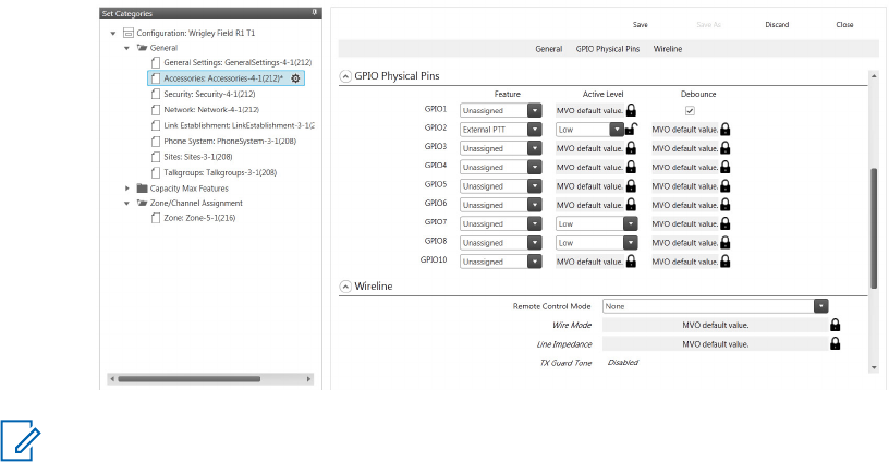
- Un-Checked or Checked
•Tx Audio Priority
- Set to 0 for console priority
• GPIO Pin number 2
- Ext PTT
- Active Low
• GPIO Pin number 5
- CSQ Detect or PL/ Talk group Detect
- Active Low
• GPIO Pin number 6
- Monitor
- Active Low
• GPIO Pin number 8
- Channel Select 1
- Active Low
Figure 41: Radio Management Configuration for L3276 Tone Remote Adapter
(For a 2-Channel Remote Control)
NOTICE: This configuration is considered typical. The L3276 Remote Tone Adapter provides
alternate configurations that are supported by the repeater as well. See the L3276 Remote
Tone Adapter manual for additional details.
Tone Remote Adapter Settings
The input and output levels should be adjusted per the Tone Remote Adapter’s instructions. The
summary below gives a brief overview of the high level characteristics and typical Tone Remote
Adapter settings for configuration with the SLR 1000 Repeater.
Radio Rx
The Receiver audio yields 330 mV rms into 50 kΩ with an RF input signal deviating at 60% RSD. With
the Remote Tone Adapter's own loading impedance, the "Radio Rx" signal delivered to the phone
MN003557A01-AA
Appendix D: SLR 1000 Series Third Party Controllers
Send Feedback 97
Preliminary FCC Filing
patch is at a high enough drive level to leave jumper S10 in the factory default position (position is
"out").
Radio Tx
The transmitter yields 60% RSD with 80mV rms into the Tx Audio port. The “Radio Tx” signal delivered
by the Remote Tone Adapter is at a high enough drive level to leave jumper S9 in the factory default
position (position A).
Channel Steering
Leave Jumper S7 in position B (factory default) to match the SLR 1000 Series Repeater's active low
setting for the Channel Steering 1 signaling.
Monitoring
Leave jumper S8 in the “IN” position (factory default) to match the active low setting for the Monitor
GPIO signaling.
PTT
Leave jumper S5 in the “IN” position (factory default) to match the active low setting for the PTT GPIO
signaling.
Wildcard 1 (optional)
Leave jumper S6 in position A (factory default) to match the active low setting for the Repeater
Disabled GPIO signaling.
MN003557A01-AA
Appendix D: SLR 1000 Series Third Party Controllers
98 Send Feedback
Preliminary FCC Filing

Appendix E: MOTOTRBO Repeater
EME Assessment
NOTICE: The example in this Appendix applies for a UHF band system. For different frequency
bands, applicable band-specific parameters should be employed to carry out the computations
yielding band-specific compliance boundaries.
Executive Summary
Compliance is established with respect to the U.S. FCC regulations [11] in a typical system
configuration of the MOTOTRBO SLR 1000 Repeater described in the following as derived.
A computational assessment was carried out to provide an estimation of the EME exposure and
compliance distances relative to the FCC ID ABZ99FT4100, Model AAR11SDGANQ1AN with
HKAE4003_, HKAE4004_, and HKAE4005_ antennas.
The following table provides the compliance distances for general public and occupational-type
exposure, for the UHF frequency band, antenna, and parameters considered in this analysis, based on
a typical system configuration:
Table 28: Indoor EME Compliance Distances Based on Example UHF Evaluation
Compliance distances Peak 1-g Average SAR Whole-Body SAR
General public exposure 40 cm 40 cm
Occupational-type exposure 40 cm (*) 40 cm (*)
Table 29: Outdoor EME Compliance Distances Based on Example UHF Evaluation
Compliance distances Peak 1-g Average SAR Whole-Body SAR
General public exposure 67 cm 67 cm
Occupational-type exposure 14 cm (*) 14 cm (*)
(*) This distance is very conservative and may be reduced significantly by carrying out a specific
occupational exposure analysis. The present analysis comprises a single distance suitable for both
exposure conditions.
Device Power Characteristics
The technical characteristics of the FCC ID ABZ99FT4100 Model AAR11SDGANQ1AN are as follows:
• Transmit Frequency Range: 400–527 MHz
• Maximum Power: 10 W
• Maximum Duty Cycle: 100%
• Antenna Information:
- Frequency Range: 400–530 MHz
- Monopole (17 cm)
- Peak Gain: 4.1 dBi
MN003557A01-AA
Appendix E: MOTOTRBO Repeater EME Assessment
Send Feedback 99
Preliminary FCC Filing
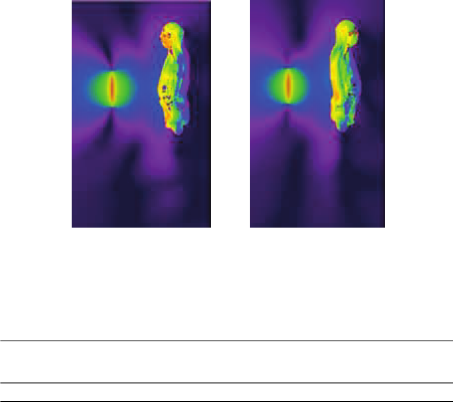
Outdoor Exposure Prediction Model
This section describes how to determine the outdoor exposure model prediction of an antenna.
Whole-Body SAR Compliance
Full-wave and half-wave simulations are represented to show the exposure conditions.
The full-wave simulations based on the FDTD method were performed at 400 MHz and 470 MHz which
includes the operating band of the evaluated antenna. The simulation code employed was XFDTD,
version 7.3 by Remcom Inc., State College, PA. The exposed subject was modeled by a
heterogeneous full body model standardized for SAR evaluation according to the IEC/IEEE 62704-2
draft standard [12].
The half-wave dipole antenna and maximum radiated power were used to represent the exposure
condition. At each frequency, two individual simulations representing the exposure from the front and
back at 40 cm distance from the dipole were conducted. No losses other than dissipation of RF energy
inside the human body were assumed in the FDTD modeling, which provides an extra degree of
overestimation.
Figure 42: H-Field and SAR Distributions for Exposure from a Dipole Antenna
Table 30: Whole-Body Average SAR Results on page 100 presents the whole-body average SAR
results for the simulated conditions at. To account for the actual measured antenna gain of 4.1 dBi
which is higher than the half -wave dipole gain by factor of 1.57 the whole-body average results were
scaled by that factor and are present in a separate column as adjusted whole-body SAR values
alongside.
Table 30: Whole-Body Average SAR Results
Table Num-
ber
Frequency MHz Antenna Posi-
tion
Whole-Body
SAR W/kg
Adjusted
Whole-Body
SAR, W/kg
1 400 Front 0.010 0.016
Table continued…
MN003557A01-AA
Appendix E: MOTOTRBO Repeater EME Assessment
100 Send Feedback
Preliminary FCC Filing
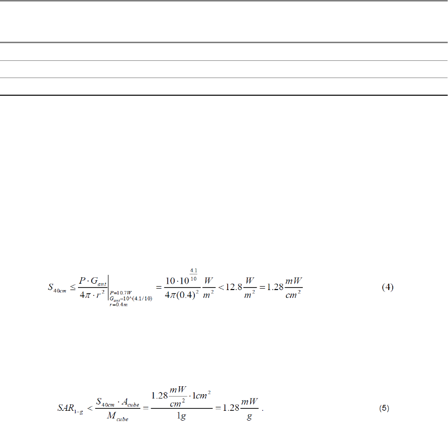
Table Num-
ber
Frequency MHz Antenna Posi-
tion
Whole-Body
SAR W/kg
Adjusted
Whole-Body
SAR, W/kg
2 400 Back 0.012 0.019
5 470 Front 0.010 0.016
6 470 Back 0.012 0.019
The highest adjusted whole-body average SAR value from these simulations is 0.019 W/kg. This value
is below the US FCC whole-body SAR limits for both controlled (occupational) and general public
exposure environments, 0.4 W/kg and 0.08 W/kg, respectively.
Peak 1-g Average SAR Compliance
The maximum measured gain of the antenna is used in this assessment to produce the conservative
evaluation of exposure in the operating condition of the radio.
The compliance relative to the US FCC limits for the peak 1-g average SAR [11] is evaluated at p=40
cm from the antenna by estimating an upper bound for said quantity. Evaluation of the peak power
density at 40 cm distance is performed based on maxim radiated power P =10 W and maximum
antenna gain Gant = 4.1 dBi:
Making the further conservative assumption that, at the point of maximum exposure, the whole
impinging power over a cross-section equal to one face of a 1-g cube of tissue (an area equal to 1cm2
assuming that the tissue density is 1g/cm3) is absorbed by the body inside that cube, the following
upper bound for the peak 1-g average SAR is derived.
This value is below the US FCC peak 1-g average SAR limits [11] for both controlled (occupational)
and uncontrolled (general public) environments, 8 W/kg and 1.6 W/kg, respectively.
MN003557A01-AA
Appendix E: MOTOTRBO Repeater EME Assessment
Send Feedback 101
Preliminary FCC Filing
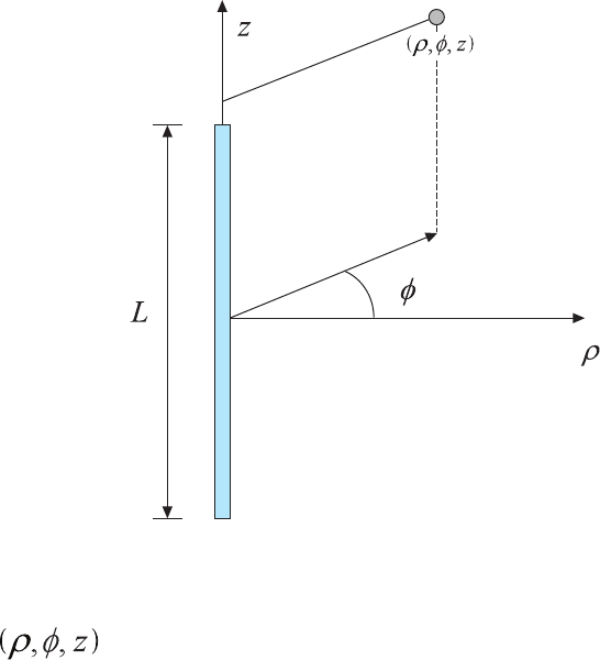
Indoor Exposure Prediction Model
This section describes how to determine the indoor exposure model prediction of an antenna or at
ground level.
Exposure in Front of the Antenna
The cylindrical-wave model defined in Clause 8.3.4 of the EN50383:2010 standard is applied to
determine the compliance boundaries for workers and general public for a typical system configuration
of the SLR 1000 Repeater.
Figure 43: Reference Frame for the Point of Interest (POI) Cylindrical Co-Ordinates
POI
Per the reference frame in Figure 43: Reference Frame for the Point of Interest (POI) Cylindrical Co-
Ordinates on page 102, the cylindrical-wave model is applicable in the volume described in cylindrical
co-ordinates for omni-directional array antennas as follows:
MN003557A01-AA
Appendix E: MOTOTRBO Repeater EME Assessment
102 Send Feedback
Preliminary FCC Filing
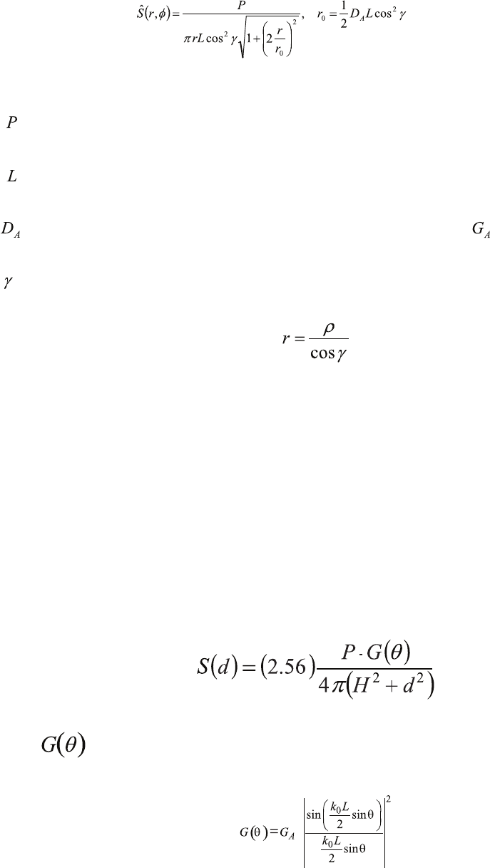
(1)
where
available power at the antenna port (W);
physical antenna length (metres);
peak antenna directivity (unit-less), assumed equal to the peak gain ;
electrical down-tilt angle of the antenna main beam (radians), and
is the distance from the antenna center (metres). Spatial power density averaging may be required by
some regulations. As the formula (1) predicts the peak power density, it represents a conservative
estimate of the average power density. Thus there is no need to compute the latter.
Exposure at Ground Level
Several methods can be employed to determine the EME exposure at ground level.
Such an assessment is not necessary if the mounting height of the antenna is larger than the
compliance distance in front of the antenna, computed using the EN50383:2010 methodology outlined
in
Exposure in Front of the Antenna on page 102. If this is not feasible, then the following approach can
be employed.
At ground level exposure occurs in the antenna far-field. The antenna phase center is assumed to be
the mounting height. The resulting predictive equation for the power density is:
where is the elevation gain pattern, which is approximated by the following expression:
MN003557A01-AA
Appendix E: MOTOTRBO Repeater EME Assessment
Send Feedback 103
Preliminary FCC Filing
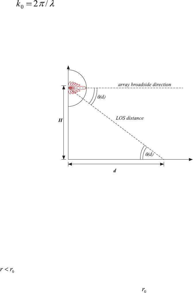
where is the free-space wavenumber and L is the effective antenna length yielding
the appropriate vertical beamwidth, while H is the antenna height above ground and d is the point of
interest (POI) distance from the vertical antenna projection to ground (see the following figure). The
multiplicative factor 2.56 is introduced to enforce near-perfect, in-phase ground reflection as
recommended in [2]. In this case, spatial averaging is not carried out to make the EME exposure
assessment more conservative.
Figure 44: Schematic of the Ground-Level Exposure Model Adopted for the Assessment
Typical System Configuration
The SLR 1000 Repeater operates in different frequency ranges with different channels transmitting 10
W radio frequency (RF) power.
The typical system configuration comprises an omnidirectional array antenna featuring 6–10 dBd gain,
installed at or above 20 m from ground level, and fed by the repeater through a combiner characterized
by a typical 3 dB transmission loss, and a 30 m 7/8" coaxial cable characterized by a typical 2.7 dB/
100m loss, resulting in a total 3.9 dB transmission loss. Based on these characteristics, the RF power
at the antenna input is about 20 W.
Since shorter antennas provide a conservative EME exposure assessment from equation (1), when
, the parameters of a typical 6.6 dBd antennas are employed (it has to be verified that the
resulting compliance distances are indeed smaller than ). Such an antenna (such as, Andrew
DB408) would exhibit a typical elevation beamwidth of about 14 degrees.
Exposure Limits
Guidelines are used for the EME exposure assessment.
Based on the operating frequency range, the most conservative power density limits are those defined
in the ICNIRP guidelines [1]. The guidelines are 10.1 W/m2 for occupational exposure, and 2.02 W/m2
for general public exposure.
MN003557A01-AA
Appendix E: MOTOTRBO Repeater EME Assessment
104 Send Feedback
Preliminary FCC Filing
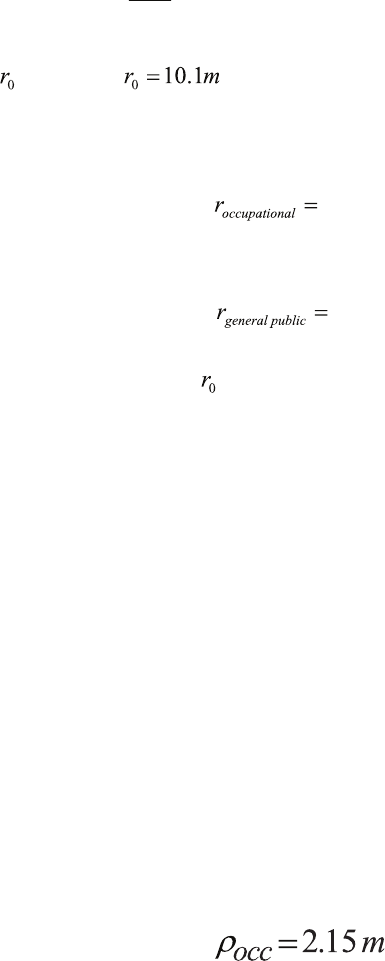
EME Exposure Evaluation
This section describes how to evaluate the EME exposure of an antenna or at ground level.
Exposure in Front of the Antenna
The assessment is based on the following characteristics of the Andrew DB408 antenna:
6.6
+
2.15
GA = 10 10 = 7.5 P = 22.9 W
γ
= 0 L = 2.7 m
The parameter is thus . Upon inserting the power density limits established in
Exposure Limits on page 104 into formula (1), the following distances for occupational and general
public exposure compliance are respectively determined:
14cm
and
67cm
As both these distances are less than , the aforementioned choice (Typical System
Configuration on page 104) of considering the shorter, lower gain antenna to perform the assessment
is deemed valid. Longer, higher gain antennas would yield shorter compliance distances, for the same
input antenna power and operating frequency range.
Exposure at Ground Level
Since the antenna installation height above ground level in the typical system configuration (20 m) is
larger than either of the compliance distances determined in Exposure in Front of the Antenna, the
EME exposure at ground level is always compliant with the exposure limits defined in the ICNIRP
guidelines.
Compliance Boundary Description
Based on the analysis in EME Exposure Evaluation on page 105, the compliance boundaries for
occupational and general public exposure are defined as cylinders enclosing the antenna (see Figure
45: Compliance Boundary for General Public (GP) and Ocupational (OCC) Exposure on page 106),
extending 75 cm (one wavelength) above and below the physical antenna, with radii:
Occupational exposure:
General Public exposure:
MN003557A01-AA
Appendix E: MOTOTRBO Repeater EME Assessment
Send Feedback 105
Preliminary FCC Filing
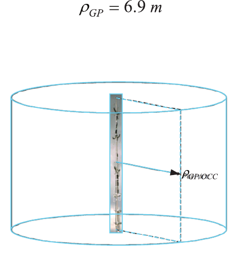
Figure 45: Compliance Boundary for General Public (GP) and Ocupational (OCC) Exposure
Product Put In Service
Some regulations require that additional exposure assessments be performed when putting the
product in service, to account for antenna site-specific circumstances such as the environment
(such as, electromagnetic scatterers) and other antennas. In such cases, certain standards [7]–[10]
may need to be considered to determine the most suitable compliance assessment methodology.
References
1International Commission on Non-Ionizing Radiation Protection (ICNIRP), "Guideline for Limiting
Exposure to Time-Varying Electric, Magnetic, and Electromagnetic Fields", Health Physics, vol. 74,
no. 4, pp. 494-522, April 1998.
2United States Federal Communication Commission, "Evaluating compliance with FCC guidelines
for human exposure to radio frequency electromagnetic fields", OET Bulletin 65, Ed. 97-01, Section
2 (Prediction Methods), August 1997.
3US Code of Federal Regulations, Title 47, Volume 1, Sec. 1.1310 Radio frequency radiation
exposure limits (Revised as of October 1, 2003).
http://edocket.access.gpo.gov/cfr_2003/octqtr/47cfr1.1310.htm.
4EN 50383:2010. Basic standard for the calculation and measurement of electromagnetic field
strength and SAR related to human exposure from radio base stations and fixed terminal stations
for wireless telecommunication systems (110 MHz–40 GHz). CENELEC (European Committee for
Electrotechnical Standardization).
5EN 50384:2002. Product standard to demonstrate the compliance of radio base stations and fixed
terminal stations for wireless telecommunication systems with the basic restrictions or the reference
levels related to human exposure to radio frequency electromagnetic fields
MN003557A01-AA
Appendix E: MOTOTRBO Repeater EME Assessment
106 Send Feedback
Preliminary FCC Filing
(110 MHz–40 GHz). Occupational. CENELEC (European Committee for Electrotechnical
Standardization).
6EN 50385:2002. Product standard to demonstrate the compliance of radio base stations and fixed
terminal stations for wireless telecommunication systems with the basic restrictions or the reference
levels related to human exposure to radio frequency electromagnetic fields
(110 MHz–40 GHz). General public. CENELEC (European Committee for Electrotechnical
Standardization).
7EN 50401:2006. Product standard to demonstrate the compliance of fixed equipment for radio
transmission (110 MHz–40 GHz) intended for use in wireless telecommunication networks with the
basic restrictions or the reference levels related to general public exposure to radio frequency
electromagnetic fields, when put into service. CENELEC (European Committee for Electrotechnical
Standardization).
8EN 50400:2006. Basic standard to demonstrate the compliance of fixed equipment for radio
transmission (110 MHz–40 GHz) intended for use in wireless telecommunication networks with the
basic restrictions or the reference levels related to general public exposure to radio frequency
electromagnetic fields, when put into service. CENELEC (European Committee for Electrotechnical
Standardization).
9EN 50492:2008. Basic standard for the in-situ measurement of electromagnetic field strength
related to human exposure in the vicinity of base stations. CENELEC (European Committee for
Electrotechnical Standardization).
10 IEC 62232:2011. Determination of RF field strength and SAR in the vicinity of radiocommunication
base stations for the purpose of evaluating human exposure. IEC (International Electrotechnical
Commission).
11 United States Federal Communication Commission, “Evaluating compliance with FCC guidelines for
human exposure to radio frequency electromagnetic fields,” OET Bulletin 65 (Ed. 97-01), August
1997. Supplement C (Edition 01-01) to US FCC OET Bulletin 65 (Edition 97-01), “Additional
Information for Evaluating Compliance of Mobile and Portable Devices with FCC Limits for Human
Exposure to Radio frequency Emissions,” June 2001.
12 IEC/IEEE 62704-2, Determining the peak spatial-average specific absorption rate (SAR) in the
human body from wireless communications devices, 30 MHz to 6 GHz – Part 2: Specific
requirements for finite difference time domain (FDTD) modeling of exposure from vehicle mounted
antennas. Draft, Dec 11, 2015.
MN003557A01-AA
Appendix E: MOTOTRBO Repeater EME Assessment
Send Feedback 107
Preliminary FCC Filing
This page intentionally left blank.
Preliminary FCC Filing
Glossary of Terms and Acronyms
This glossary contains an alphabetical listing of terms and their definitions that are applicable to
repeater products. All terms do not necessarily apply to all radios, and some terms are merely generic
in nature.
Alert tone
Audio signal produced by the station, providing feedback to the user.
Analog
Refers to a continuously variable signal or a circuit or device designed to handle such signals.
ASIC
Application Specific Integrated Circuit.
AUX
Auxiliary.
Band
Frequencies allowed for a specific purpose.
CTCSS
Continuous Tone-Controlled Squelch Systems (PL).
Clear
Channel modulation type in which voice information is transmitted over the channel using analog
modulation.
Conventional
Term used for standard non-trunked radio system (usually using TRC/DC console).
CPS
Customer Programming Software: Software with a graphical user interface containing the feature set of
a radio.
Default
A pre-defined set of parameters.
Digital
Refers to data that is stored or transmitted as a sequence of discrete symbols from a finite set; most
commonly this means binary data represented using electronic or electromagnetic signals.
DPL
Digital Private-Line: A type of digital communications that utilizes privacy call, as well as memory
channel and busy channel lock out to enhance communication efficiency.
MN003557A01-AA
Glossary of Terms and Acronyms
Send Feedback 109
Preliminary FCC Filing
DSP
Digital Signal Processor, microprocessor specifically designed to perform digital signal processing
algorithms.
EIA
Electronic Industries Association.
ESD
Electro Static Discharge.
EU
European Union.
FCC
Federal Communications Commission.
FM
Frequency Modulation.
Frequency
Number of times a complete electromagnetic-wave cycle occurs in a fixed unit of time (usually one
second).
FRU
Field Replaceable Unit.
FSK
Frequency Shift Keying.
GNSS
Global Navigation Satellite System.
GPIO
General Purpose Input/Output.
IC
Integrated Circuit: An assembly of interconnected components on a small semiconductor chip, usually
made of silicon. One chip can contain millions of microscopic components and perform many functions.
IF
intermediate frequency.
I/O
Input or Output.
kHz
kilohertz: One thousand cycles per second. Used especially as a radio-frequency unit.
MN003557A01-AA
Glossary of Terms and Acronyms
110 Send Feedback
Preliminary FCC Filing
LCD
Liquid-Crystal Display: An LCD uses two sheets of polarizing material with a liquid-crystal solution
between them. An electric current passed through the liquid causes the crystals to align so that light
cannot pass through them.
LED
Light Emitting Diode: An electronic device that lights up when electricity is passed through it.
MDC
Motorola Data Communications. 1200 or 4800 baud data signalling scheme.
MHz
Megahertz: One million cycles per second. Used especially as a radio-frequency unit.
MISO
Master In, Slave Out.
MOSI
Master Out, Slave In.
PA
Power Amplifier that transmits final RF signal to transmit antenna.
PC Board
Printed Circuit Board. Also referred to as a PCB.
PFC
Power Factor Correction.
PL
Private-Line Tone Squelch: A continuous sub-audible tone that is transmitted along with the carrier.
Programming Cable
A cable that allows the Radio Management to communicate directly with the radio using RS232.
PTT
Push-to-talk; the switch located on the left side of the radio which, when pressed causes the radio to
transmit.
Radio Management
Software with a graphical user interface containing the feature set of a device.
Receiver
Electronic device that amplifies RF signals. A Receiver separates the audio signal from the RF carrier,
amplifies it, and converts it back to the original sound waves.
MN003557A01-AA
Glossary of Terms and Acronyms
Send Feedback 111
Preliminary FCC Filing
Repeater
Remote transmit/receive facility that retransmits received signals in order to improve communications
range and coverage.
RF
Radio Frequency: The portion of the electromagnetic spectrum between audio sound and infrared light
(approximately 10 kHz to 10 GHz).
RSSI
Received Signal Strength Indicator; a dc voltage proportional to the received RF signal strength.
Rx
Receive.
SCM
Station Control Module; station controller.
SELV
Separated Extra Low Voltage.
Signal
An electrically transmitted electromagnetic wave.
SINAD
Acronym for the ratio of signal plus noise plus distortion and noise plus distortion.
SLR
Refers to Digital Professional Repeater model names in the MOTOTRBO Professional Digital Two-
Way Radio System.
Spectrum
Frequency range within which radiation has specific characteristics.
SPI
Serial Peripheral Interface (clock and data lines); simple synchronous serial interface for data transfer
between processors and peripheral ICs.
Squelch
Muting of audio circuits when received signal levels fall below a pre-determined value. With carrier
squelch, all channel activity that exceeds the radio’s preset squelch level can be heard.
TOT
Time-out Timer: A timer that limits the length of a transmission.
TPL
Tone Private Line.
MN003557A01-AA
Glossary of Terms and Acronyms
112 Send Feedback
Preliminary FCC Filing
Transceiver
Transmitter-Receiver. A device that both transmits and receives analog or digital signals. Also
abbreviated as XCVR.
Transmitter
Electronic equipment that generates and amplifies an RF carrier signal, modulates the signal, and then
radiates it into space.
Trunking
Radio control system which permits efficient frequency utilization and enhanced control features.
Tx
Transmit.
UHF
Ultra High Frequency.
USB
Universal Serial Bus: An external bus standard that supports data transfer rates of 12 Mbps.
VCO
Voltage-Controlled Oscillator; an oscillator whereby the frequency of oscillation can be varied by
changing a control voltage.
VCTCXO
Voltage Controlled Temperature Compensated Crystal Oscillator.
VHF
Very High Frequency.
VIP
Vehicle Interface Port.
VSWR
Voltage Standing Wave Ratio.
WLAN
Wireless Local Area Network.
MN003557A01-AA
Glossary of Terms and Acronyms
Send Feedback 113
Preliminary FCC Filing
This page intentionally left blank.
Preliminary FCC Filing