Motorola Solutions 99FT7001 Remote Speaker Microphone User Manual
Motorola Solutions, Inc. Remote Speaker Microphone
Exhibit D Users Manual per 2 1033 b3
Accessories
Wireless
Remote Speaker Microphone (RSM)
6880309K15-O
Model HMN3158

and MOTOROLA are registered trademarks of Motorola, Inc.
The BLUETOOTH trademarks are owned by Telefonaktiebolaget LM Ericsson,
Sweden, and licensed to Motorola, Inc.
1
TABLE OF CONTENTS
Safety and General Information. . . . . . . . . . . . . . . . .3
Electromagnetic Interference/Compatibility
Facilities. . . . . . . . . . . . . . . . . . . . . . . . . . . . . . . . .4
Aircraft. . . . . . . . . . . . . . . . . . . . . . . . . . . . . . . . . .4
Medical Devices. . . . . . . . . . . . . . . . . . . . . . . . . . .4
Bluetooth Wireless Technology Overview . . . . . . . . .6
Getting Started
Installing Your Batteries. . . . . . . . . . . . . . . . . . . . .8
Attaching and Removing the Belt Clip . . . . . . . . . .9
Wearing Your RSM . . . . . . . . . . . . . . . . . . . . . . . .9
Turning ON Your RSM . . . . . . . . . . . . . . . . . . . . .10
Establishing the Bluetooth Wireless
Connection. . . . . . . . . . . . . . . . . . . . . . . . . . . .10
Connection Verification . . . . . . . . . . . . . . . . . . . .11
Lost Link . . . . . . . . . . . . . . . . . . . . . . . . . . . . . . .11
Turning Off Your RSM . . . . . . . . . . . . . . . . . . . . .12
Disconnecting the Bluetooth Wireless
Connection. . . . . . . . . . . . . . . . . . . . . . . . . . . .12
LED Indicators. . . . . . . . . . . . . . . . . . . . . . . . . . .13
Operation
Operational Range . . . . . . . . . . . . . . . . . . . . . . . .14
Receiving. . . . . . . . . . . . . . . . . . . . . . . . . . . . . . .14
Transmitting. . . . . . . . . . . . . . . . . . . . . . . . . . . . .14
Volume Control . . . . . . . . . . . . . . . . . . . . . . . . . .15
Earphone Jack . . . . . . . . . . . . . . . . . . . . . . . . . . .15
2
Battery
Low Battery Alert. . . . . . . . . . . . . . . . . . . . . . . . .16
Battery Life . . . . . . . . . . . . . . . . . . . . . . . . . . . . .17
Battery Replacement Options . . . . . . . . . . . . . . .17
Temperature Effects On Your RSM. . . . . . . . . . . . . .18
Replacement Parts List . . . . . . . . . . . . . . . . . . . . . .18
Accessories . . . . . . . . . . . . . . . . . . . . . . . . . . . . . . .18
Battery Replacements . . . . . . . . . . . . . . . . . . . . . . .19
Service and Support. . . . . . . . . . . . . . . . . . . . . . . . .19
Warranty . . . . . . . . . . . . . . . . . . . . . . . . . . . . . . . . . .19
Disassembling and Reassembling the RSM . . . . . .20
3
SAFETY AND GENERAL INFORMATION
IMPORTANT INFORMATION ON SAFE AND
EFFICIENT OPERATION.
READ THIS INFORMATION BEFORE USING
YOUR RADIO.
Users are not permitted to make changes or
modify the device in any way. Changes or modifi-
cations not expressly approved by the party
responsible for compliance could void the user’s
authority to operate the device. See 47 CFR Sec.
15.21.
This device complies with Part 15 of the U.S.
FCC Rules. Operation is subject to the following
two conditions:
(1) This device may not cause harmful interfer-
ence, and (2) this device must accept any inter-
ference received, including interference that may
cause undesired operation. See 47 CFR Sec.
15.19(3).
4
ELECTROMAGNETIC INTERFERENCE/
COMPATIBILITY
OTE: Nearly every electronic device is sus-
ceptible to electromagnetic interference
(EMI) if inadequately shielded, designed
or otherwise configured for electromag-
netic compatibility.
Facilities
To avoid electromagnetic interference and/or
compatibility conflicts, turn off your device in any
facility where posted notices instruct you to do so.
Hospitals or health care facilities may be using
equipment that is sensitive to external RF energy.
Aircraft
When instructed to do so, turn off your device
when on board an aircraft. Any use of your device
must be in accordance with applicable regula-
tions per airline crew instructions.
Medical Devices
Pacemakers
The Health Industry Manufacturers Association
recommends that a minimum separation of 6
inches (15 centimeters) be maintained between a
N
5
wireless device and a pacemaker. These recom-
mendations are consistent with the independent
research by, and recommendations of, Wireless
Technology Research.
Persons with pacemakers should:
•ALWAYS keep the wireless device more
than 6 inches (15 centimeters) from their
pacemaker when the device is turned ON.
•not carry the device in the breast pocket.
•use the ear opposite the pacemaker to min-
imize the potential for interference.
•turn the device OFF immediately if you
have any reason to suspect that interfer-
ence is taking place.
Hearing Aids
Some digital wireless radios may interfere with
some hearing aids. In the event of such interfer-
ence, you may want to consult your hearing aid
manufacturer to discuss alternatives.
Other Medical Devices
If you use any other personal medical device,
consult the manufacturer of your device to deter-
mine if it is adequately shielded from RF energy.
Your physician may be able to assist you in
obtaining this information.
6
BLUETOOTH WIRELESS TECHNOLOGY OVERVIEW
At Motorola we believe that easy portable com-
munication is the key to creating a safer environ-
ment. That’s why we designed this exciting new
two-way communication device called the
Bluetooth Wireless Remote Speaker Microphone
(RSM). The RSM represents another break-
through in applying Bluetooth wireless technol-
ogy by Motorola. The receiver and microphone
are built into a lightweight wireless speaker
microphone that provides a convenient means of
communicating by having a speaker, a micro-
phone, and a PTT button in a single hand-held or
clip-on accessory unattached to your radio.
This wireless RSM uses a new protocol based on
state-of-the-art Bluetooth technology specifica-
tions, which result in simplifying the use of your
radio. Bluetooth technology is an open standard,
connecting wireless devices within a short range.
The range for this particular RSM is approxi-
mately 30 feet in ideal line-of-sight conditions. It
is important to be aware that the specific Blue-
tooth technology was designed and engineered
for use between your RSM and Bluetooth capa-
ble radio. This Bluetooth RSM will not operate
with other non-Motorola two-way radio Bluetooth
products.
7
We’re confident that once you try the Bluetooth
wireless RSM, you’ll wonder how you survived
with all those attachment wires in the first place!
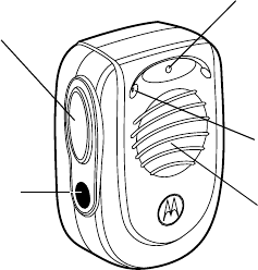
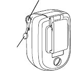
LED Indicator
Light
Indicates when
RSM is functioning
properly; also
battery life indicator
Microphone
Picks up
audible
transmission
Speaker
Broadcasts
audible
transmissions
Push-To-Talk (PTT) Button
Used to transmit messages
BLUE Button
Used in conjunction
Figure 1. Remote Speaker Microphone
and turn on
with PTT to::
connect
disconnect
turn off
8
GETTING STARTED
Installing Your Batteries
Included with your RSM are three (3) AA alkaline
batteries. These must be installed for the RSM to
work. To do this, follow these steps:
1. Remove the battery cover by inserting a coin or
other thin object into the screw slot (See
Figure 2). Turn the screw counter-clockwise.
2. Install three (3) AA batteries in the correct
position.
3. Place the battery cover back onto the RSM
and turn the battery cover screw clockwise
until it is tight.
OTE: Be careful to place the AA batteries in
their correct polarity indicated positions
(+ positive, – negative).
N
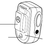
Belt Clip
For attaching RSM
Battery Cover Screw
Used to open compartment and replace batteries
Figure 2.
Battery
Cover
9
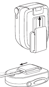
Attaching and Removing the Belt Clip
To Attach
1. Locate the grooved rails on
the back of the RSM.
2. Align the mounting rails of
the belt clip with the
grooved rails on the back
of the RSM. Slide the belt
clip up the grooved rails
until it clicks into place.
To Remove
1. Locate the belt clip
release tab at the bot-
tom of the belt clip.
2. Insert a small screw-
driver between the release tab and the back
surface of the RSM.
3. Slide the belt clip down and off the RSM.
Wearing Your RSM
For optimum performance from your RSM, use it
within 30 feet of your radio or attach it using the
belt clip (See Figure 2). Wearing your RSM on
different locations of your body may result in vary-
ing reception. Adjust the RSM accordingly to
attain maximum reception quality.
10
Turning ON Your RSM
Press and hold the RSM PTT button to turn it ON.
•The RSM LED lights GREEN for one sec-
ond, indicating successful power-up.
•An audio alert tone sounds.
Establishing the Bluetooth Wireless Connection
Following these simple steps establishes a new
connection when your RSM and radio are first
tuned on:
1. Turn ON your Bluetooth capable radio. (Refer
to your radio or Radio Bluetooth Adapter
(RBA) manual).
2. Turn ON the RSM.
3. Place the RSM next to the radio. (For best
results keep both within a few inches of each
other.)
•The RSM LED lights GREEN for one sec-
ond then flashes ORANGE until a connec-
tion is established. If a connection has not
been established, the LED flashes RED.
•Once the RSM and radio have connected,
the RSM LED lights GREEN for one sec-
ond then flashes GREEN every 5 seconds.
•Once a connection is established, an audio
alert tone sounds.
11
Connection Verification
You may want to verify the connection before you
start communicating.
Press and hold the radio adapter BLUE button,
then press the RSM PTT button.
•The RSM and radio adapter LEDs light
solid for the duration of the RSM PTT
press. If this does not happen, the connec-
tion was not established and the connection
process will have to be repeated.
OTE: The color of the RSM LED corresponds
to the battery life color scheme. Refer
to“Low Battery Alert” on page 16.
Lost Link
If the connection is lost at any time, an audio alert
tone sounds and the the RSM LED lights RED for
one second then flashes ORANGE until the con-
nection is re-established. If a connection has not
been re-established within 30 seconds the LED
flashes RED.
OTE: The RSM can only make a connection
with one Bluetooth capable radio at a
time.
N
N
12
Turning OFF Your RSM
You can turn off your RSM to save battery power
without losing memory with the connection to the
radio. The next time the RSM is turned on, the
connection re-establishes at a faster rate than
compared with the intial connection.
1. Press both the RSM BLUE and PTT buttons
for more than 3 seconds until an audio alert
tone sounds.
•The RSM LED flashes RED for one second.
•The RSM powers down.
OTE: The RSM turns off within 3 minutes if no
connection is re-established and no but-
tons are pressed.
Disconnecting the Bluetooth Wireless Connection
You can disconnect and re-establish the connec-
tion when both the RSM and radio are still on.
1. Press both the RSM BLUE and PTT buttons
for less than 3 seconds.
•The RSM LED flashes RED, indicating the
connection is broken.
•An audio alert tone sounds.
2. To re-establish the connection while both the
RSM and radio are still on, place the RSM
within a few inches of the radio. Press both
the radio adapter’s BLUE and PTT buttons,
then immediately press both the RSM’s
BLUE and PTT buttons.
N

13
LED Indicators
The RSM LED is “Dual Functional” and indicates
power/connection status and battery life during
transmit and receive.
RSM
LED
Indicator Power
Connection Status Battery
Indicator
GREEN Solid GREEN for 1 second, indicates success-
ful RSM power-up, or... Battery life
is greater
than
approxi-
mately
10 hours.
Solid GREEN for 1 second, indicates success-
ful connection with an accessory, or...
Solid GREEN for duration of the PTT button
press or when receiving, indicates the RSM is
functioning correctly.
Flashing
GREEN Flashes GREEN every few seconds when
connected to the radio and no reception or
transmission is taking place.
ORANGE Solid ORANGE for duration of the PTT button
press or when receiving, indicates the RSM is
functioning correctly.
Battery life
is approxi-
mately
between
10 and 2
hours.
Flashing
ORANGE Flashes ORANGE every few seconds, indi-
cates the RSM is attempting to connect or
reconnect to the accessory.
RED Solid RED for 1 second followed by flashing
orange; indicates that connection is lost and is
attempting to reconnect to the accessory, or...
Battery life
is less than
approxi-
mately
2 hours.
Solid RED for 1 second, indicates when the
RSM is powered down, or...
Solid RED for duration of the PTT button
press or when receiving, indicates the RSM is
functioning correctly.
Flashing
RED Flashes RED every few seconds, indicates con-
nection is lost or intentionally disconnected and
has not been re-established with the radio.
14
OPERATION
Operational Range
For optimum performance from your RSM, use it
within 30 feet of your Bluetooth wireless capable
radio. This range will vary depending on environ-
mental conditions.
Receiving
Once the RSM is connected to your radio, the
radio speaker mutes and the audio is heard only
from the speaker in the RSM.
•While receiving, the RSM LED remains lit
for the duration of the received reception.
The color of the LED corresponds to the
battery life color scheme. Refer to “Low
Battery Alert” on page 16.
Transmitting
The Push-To-Talk (PTT) button on either the
RSM, the radio adapter, or the radio initiate trans-
mission. Depending upon your radio, there can
be different PTT buttons to press. Pressing any
one of these buttons determines which micro-
phone is active.
OTE: Pressing the RSM or radio adapter PTT
button activates only the microphone in
the RSM.
N
15
OTE: Pressing the radio PTT button activates
only the microphone in the radio.
•While transmitting, the RSM LED lights
solid for the duration of the PTT button
press. The color of the LED corresponds to
the battery life color scheme. Refer to “Low
Battery Alert” on page 16.
Volume Control
There is no volume control on this RSM. The vol-
ume must be controlled using the radio’s volume
control.
Earphone Jack
Your RSM includes a 3.5mm
unthreaded earphone jack to
receive audio discretely. Once
the earphone is connected to
your RSM, the RSM speaker
mutes and the audio is heard
through the earphone.
Motorola earphones can be
purchased separately for use
in the earphone jack.
N
Earphone Jack
Dust
Cover

16
BATTTERY
Low Battery Alert
The RSM battery life is indicated by the color of
the RSM LED when the PTT button is pressed
to transmit or when the RSM is receiving a trans-
mission.
It is recommended to replace the batteries within 2
hours of when the RSM LED first turns a solid RED.
OTES: When the LED light turns a solid
ORANGE an audible alert signals every
30 minutes.
When the LED light turns a solid RED an
audible alert signals every 5 minutes to
remind you to replace your batteries.
To ensure proper functioning of the RSM
battery meter, use only three AA alkaline
or lithium disulfide disposable batteries.
The battery life meter may not work
accurately with rechargeable batteries.
RSM LED
Color Audio Alert Approximate
RSM Battery Life
GREEN None 10 hours or more
ORANGE “Chirp” every
30 minutes 2 to 10 hours
RED “Chirp” every
5 minutes 2 hours or less
N
17
Battery Life
Your RSM is shipped with three AA Alkaline bat-
teries and provides approximately 60 hours of
use at a 5/5/90 duty cycle (5% receive / 5% trans-
mit / 90% standby). The longer you receive and/
or transmit above these levels, you will experi-
ence less battery life and will require to change
the batteries more frequently.
Battery Replacement Options
Alkaline, Nickel Cadmium (Ni-Cd), and Nickel-
Metal Hydride (Ni-MH) rechargeable batteries
can be used safely, however, the RSM was spe-
cifically designed for alkaline batteries and opti-
mal performance is achieved using these.
To increase the usage time between battery
changes it is recommended to use lithium disul-
fide (LiFeS2) Primary (disposable) AA batteries.
Using lithium disulfide disposable batteries can
provide up to 10-20% more usage time between
battery replacement depending upon the environ-
mental conditions.
Secondary (rechargeable) AA batteries can also
be used with your RSM, however, these provide
less usage time between battery replacement
compared to disposable batteries. Using
rechargeable batteries has the advantage of not

18
having to purchase as many disposable batteries
and is better for the environment.
TEMPERATURE EFFECTS ON YOUR RSM
Your RSM can be used in most environments.
However, some batteries work better in specific
climates. Alkaline, Alkaline rechargeable and Ni-
Cd/Ni-MH batteries can typically be used
between –4° F and +130° F. Lithium disulfide bat-
teries, however, will provide better performance
at lower temperatures down to –40° F.
REPLACEMENT PARTS LIST FOR HMN5138
ACCESSORIES
Description Motorola
Part Number
RSM Replacement Parts Manual 6880309K93
Earphone Jack Dust Cover 38-85835M01
Button Switch 40-80523Z01
Battery Cover Screw (1) 03-80475E01
Front Housing Kit RLN4946
Back Housing Kit RLN4947
Optional RSM Accessories Motorola
Part Number
Shoulder Clip 42-05823V01
Single Earbud w/Black Cable RLN4941
Single Earbud w/Clear Flex Cable RLN4885
Flexible Ear Receiver WADN4190

19
BATTERY REPLACEMENTS
SERVICE AND SUPPORT
The RSM is not repairable. If there is a problem
with the unit after the warranty period, please
order a replacement unit or replacement parts. To
order replacement parts or for warranty informa-
tion, contact Motorola Americas Accessories
Aftermarket Division (AAD) at:
1-800-422-4210 or 847-538-8023.
WARRANTY
The RSM is covered under the standard Motorola
one (1) year limited warranty.
Refer to your Motorola dealer for detailed infor-
mation on your RSM standard warranty.
Suggested Battery
Replacement Options Motorola
Part Number
One (1) Lithium AA Battery 60-80376E88
Package of Three (3) Alkaline AA Batteries 01-85894M01
Package of Four (4) Alkaline AA Batteries 60-80390B60
Package of 48 Motorola Alkaline AA Batteries 60-80384K75
Package of 620 Alkaline AA Batteries 60-60934A01
Package of 1000 Motorola Alkaline
AA Batteries 60-80384F16
20
DISASSEMBLING AND REASSEMBLING THE RSM
Disassembling the RSM before the one (1) year
limited warranty has expired will void the warranty.
Disassembling
1. Remove the battery cover by inserting a coin or
other thin object into the screw slot (See
Figure 2). Turn the screw counter-clockwise.
2. Remove the batteries.
3. Remove the two screws in the battery compart-
ment using a T8 Torx® driver.
4. Gently pull the front and back housings apart.
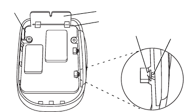
5. Gently pry the main board up from the hous-
ing using a small flat bladed screwdriver.
Refer to Figure 3 for placement of screw-
driver.
6. Lift the main board by gently grasping the
antenna and pivoting the board out of the
housing.
Reassembling
OTE: When inserting the board into the hous-
ing, make sure that the switches do not
push the rubber actuators out of place
and that both are properly aligned to one
another, as shown in Figure 3
N
21
1. Insert the main board into the housing, plac-
ing the audio jack into the housing first. Push
the board into the housing until it is properly
seated. Refer to Figure 3.
2. Align the three tabs of the front housing into
three slots the back housing.
3. Pivot the front and back housings together.
4. Make sure all rubber gaskets are properly
seated.
OTE: Make sure that the rubber gasket on the
back housing makes proper contact with
the front housing when fitting both hous-
ings together.
Antenna
Audio
Jack
Switch on PCB Rubber
Figure 3.
Attenuator
(insert screwdriver here)
N
22
5. Replace the two screws in the battery com-
partment using a T8 Torx driver and torque to
4.0 in.-lbs.
6. Replace the batteries.
7. Close the battery cover and turn the screw
clockwise until it is tight.
*6880309K15*
6880309K15-O
© 2001 by Motorola, Inc.
Printed in the U.S.A. All Rights Reserved.