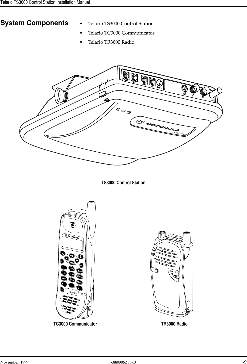
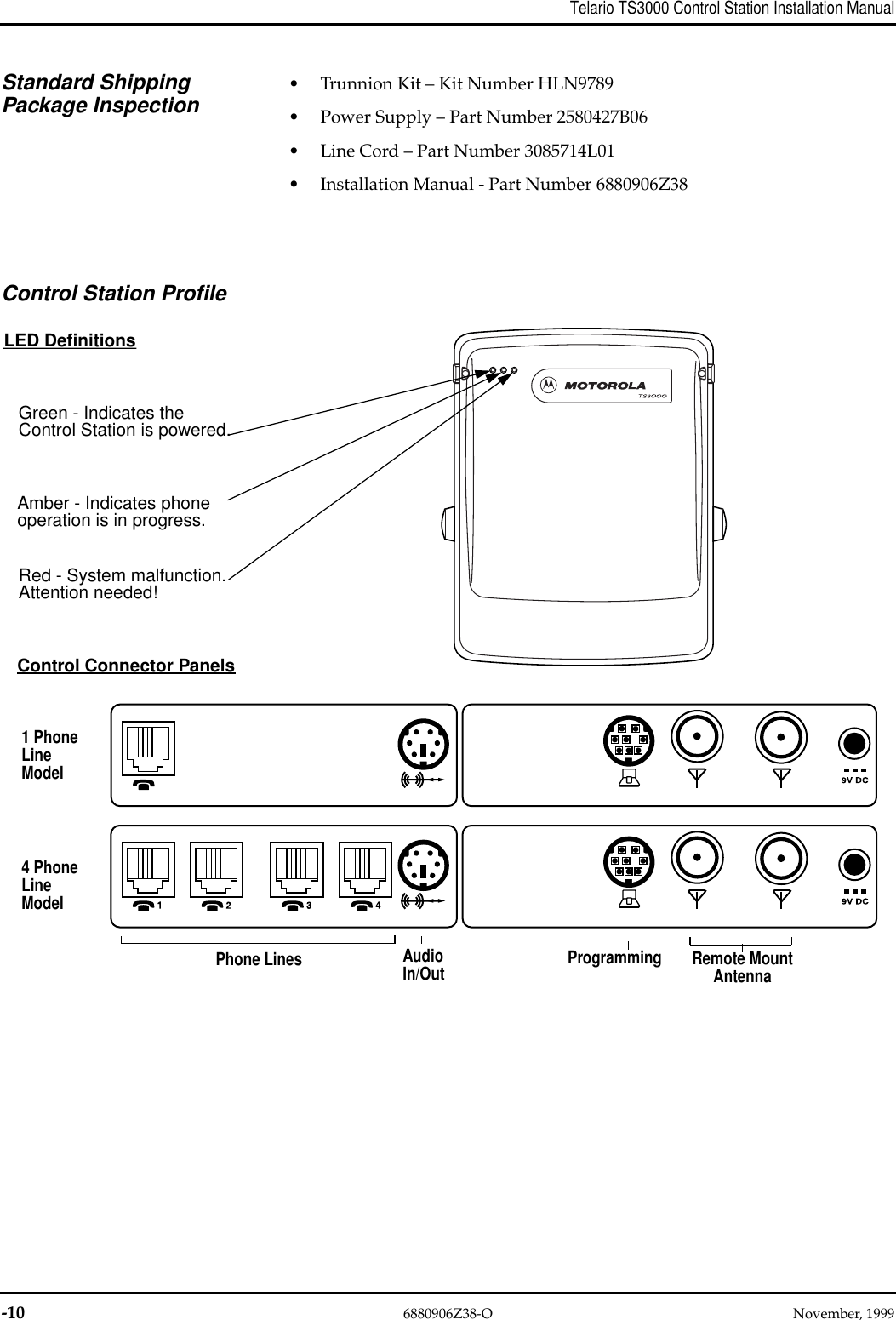
Motorola Solutions 99FT7012 Base Station User Manual

Motorola Solutions, Inc. Base Station Users Manual

Users Manual

November, 1999 6880906Z38-O -1MOTOROLATelario Installation ManualIntroduction Congratulations! You have chosen the Motorola Telario™ Integrated CordlessTelephone and Two-Way Radio System. The Telario System is a state of the artMotoroladigitalcommunications system.This productfamilyof 1.9GHz unli-censed wireless communication equipment is intended for businesses withgroups of in-building users. The system supports two types of handsets andutilizes TDMA Control Stations that allow integrated voice services to severalcommunications groups. With Motorola’s seamless integration of two-waydispatch services – Group Talk and Private Link, and Full Duplex (toll quality)CordlessTelephonecapability –your customerwill experiencean efficientandproductive work environment.Regulatory ApprovalsFCCThe TS3000 Telario Control Station complies with Part 15 and 68, FCC rules.FCC Registration Number: ABZ99FT7012Ringer Equivalence Number:This equipment complies with Part 15 and 68 of the FCC Rules. On the bottomoftheTS3000 ControlStation arelabels thatcontain, among otherinformation,the FCC Registration Number and Ringer Equivalence Number (REN) for thisequipment. If requested, this information must be given to the telephone com-pany.The REN is useful to determine the quantity of devices you many connect toyour telephone line and still have all of those devices ring when your numberis called. In most, but not all, areas, the sum of the RENs of all devices con-nected to one line should not exceed five (5.0). To be certain of the number ofdevicesyoumanyconnect to your line, asdeterminedby the REN, you shouldcontact your local telephone company to determine the maximum REN foryour calling area.If your telephone equipment causes harm to the telephone network, the tele-phone service may discontinue your service temporarily. If possible they willnotifyyouin advance. But ifadvancenoticeisn’t practical, you willbenotifiedas soon as possible. You will be informed of your right to file a complaint withthe FCC.Your telephone company may make changes in its facilities, equipment, oper-ations or procedures that could affect the proper functioning of your equip-ment. If they do, you will be notified in advance to give you an opportunity tomaintain uninterrupted telephone service.If you experience trouble with this equipment, please contact your authorizedMotoroladealer for informationonobtaining service or repairs.The telephonecompany may ask that you disconnect this equipment from the network untilthe problem has been corrected or until you are sure the equipment is not mal-functioning.This equipment has been tested and found to comply with the limits for ClassA digital device, pursuant to Part 15 of the FCC Rules. These limits aredesigned to provide reasonable protection against harmful interference whenthe equipment is operated in a commercial environment. This equipment gen-erates, uses, and can radiate radio frequency energy and, if not installed and
-2 6880906Z38-O November, 1999Telario TS3000 Control Station Installation Manualused in accordance with this installation manual, may cause harmful interfer-ence to radio communications. Operation of this equipment in a residentialarea is likely to cause harmful interference in which case the user will berequired to correct the interference at his own expense.CAUTIONCaution: If the user makes changes or modifications notexpressly approved by the party responsible for compliancecould void the user’s authority to operate the equipment.Underwriter’sLaboratories (UL)The UL symbol on the TS3000 Regulatory Label means that the product islisted by Underwriter’s Laboratories, Inc. It is designed and manufactured tomeetrigidULsafetystandardsagainstX-radiation,fire,casualty,andelectricalhazards.The following are statements required for UL certification, related to safetyprocedures that must be adhered to during installation.If wiring for a Control Station exits a building, the wiring must be protected atboth ends by a Quick Clip Fuse from Reliable Electric, model number RSCP-2.Follow these general precautions while installing telephone equipment:• Never install telephone wiring during a lightning storm.• Never install telephone jacks in wet locations unless the jack is specificallydesigned for wet locations.• Never touch uninsulated telephone wires or terminals unless the tele-phone line has been disconnected at the network interface.• Use caution when installing or modifying telephone lines.UTAMWhat is UTAM?UTAM (Unlicensed Transition & Management for Microwave Location) is anorganization which is composed of 15 companies in the United States thatcoordinatesthe relocationof existing microwaveincumbents andmanagestheunlicensed 1.9 GHz frequency range. UTAM is responsible for establishingand enforcing policies and procedures to ensure that deployment of Unli-censedPersonal CommunicationSystems (UPCS)causesnointerferencetotheincumbent microwave community. It also works to eventually move all micro-wave users out of the UPCS band.Motorola was a founding member of the organization and continues to beactively involved.Zone 1, Zone 2, & Zone 3 UnclassifiedCounties throughout all of the United States are designated as Zone 1, Zone 2or Zone 3/Unclassified, based on the status of microwave link incumbentswithin each county. UTAM procedures are both zone dependent & zone inde-pendent, and are detailed in the next sections.A county is designated as Zone 1 because all microwave incumbents havebeen cleared.A county is classified as a Zone 2 county when any microwave incumbentshave not been cleared and continue to operate in the county.
November, 1999 6880906Z38-O -3Telario TS3000 Control Station Installation ManualAn Unclassified or Zone 3 county is one that qualifies for Zone 1 status. How-ever, due to a business population being less than 5,000, it has not been sched-uled for conversion at this time. Most Unclassified counties will beautomatically converted to Zone 1 Status by UTAM when a member initiatesasite specificcoordinationrequest,with conversioncosts tobepaid byUTAM.Overall ProcessDealer contactsMotorola Product Srvcsto conduct site specificinterference analysis &frequency coordination.
-4 6880906Z38-O November, 1999Telario TS3000 Control Station Installation ManualTime of Sale, End User Contract: All ZonesAs a Dealer, it is your responsibility to inform the customer about UTAM, itsrules and regulations. This requirement applies to all zones. The followingagreement must be included in your sales contract with your customer:[Customer]herebyacknowledgesthattheuse andoperationofanyintentionalradiator equipment requiring a Part 15.311 FCC label and subject to UTAMclearing fees, the operation of which makes use of any part of the unlicensedpersonal communications services (“UPCS”) frequency spectrum (“UPCSRadiating Part”), is subject to FCC rules and regulations and UTAM require-ments and instructions including without limitation rules, regulations,requirements and instructions with respect to interference to licensed fixedmicrowave facilities and to the relocation of any such UPCS Radiating Part.[Customer] agrees that [its] use or operation of any UPCS Radiating Part shallcomply with all such rules, regulations, requirements and instructions.Name Of Subscriber:            __________________________State Of Incorporation:        __________________________By: ___________________________Name: _________________________Title: __________________________Address: _______________________Date: __________________Time of Installation, Product Registration & LVP: All ZonesTo monitor deployment and power levels, all equipment sales must be regis-tered with Motorola Product Services group at the time of installation. Infor-mation is forwarded to UTAM, per its regulations. This procedure, requiredforall zones,ensuresthat theband remainscoordinatedandoperational forallauthorized vendors and their customers.The registration form requires the following information:- Customer name- Site address- City, state, zip and county name- Site coordinates (latitude and longitude)- UTAM PFC approval number (if the location is a Zone 2 or Zone 3 site)- Quantity of Control Stations to be installed- Quantity of handsets to be installed- Installation date- Maximum height of installation
November, 1999 6880906Z38-O -5Telario TS3000 Control Station Installation Manual- Dealer information (name, contact, phone, fax)- Control station serial number(s)- 32 bit random number (request key) obtained from the Telario ManagementTool (TMT) softwareOncetheinformationisreceivedandinput,theProductServicesgroupassignsyou an authorization key for the system. The authorization key is valid for allhandsets within a system but unique for each Control Station. This authoriza-tion key is required by the Telario Management Tool (TMT) software to pro-gram the system. The Control Station is the core of the system and the serialnumberfromtheControlStationis usedtogenerate thekeycode. ProductSer-vicesuses theControlStation serialnumberandtherequestkey obtainedfromthe TMT software to generate the 18-bit authorization key, which is thenreturned to the installer. It is important to note that you can not activate theControl Station until you receive an authorization key from Motorola ProductServices (1-800-927-2744). The TMT requires entry of a valid authorization keyandoncethis has beenentered,theunit can beactivated.The unit isthenoper-ational upon completion of this programming step. In the event that a ControlStation needs to be re-registered (e.g. power down for more than 4 hours)another unique key will be required to program the unit.Use of the random hardware serial number and authorization key assures thatthe Location Verification Process (LVP) is specific to each unique system eachtime the LVP is used. The Motorola Product Services Group submits applica-tion and registration information to UTAM on a weekly basis. This informa-tion will also be kept on the database at Motorola.LVP is applicable for two main cases:1) Initial site installation:Units received by the dealer will be non-operational. The location verificationprocessandassignmentofkey codetothesitesystemisrequiredforoperation.Therefore, this process must occur at all initial installations.2) Site relocation:In the event that a Control Station (and associated handsets) is moved to a dif-ferent location, the dealer must again go through the LVP. The Telario systemensures this through the system design. The Control Station hardware andsoftwarearedesignedsothatifa ControlStationis moved(i.e.bothpowerandphoneline aredisconnected)andmorethan4hourselapse,theControlStationresets. This means that the Control Station goes back to its initial state, whichrequires a new authorization code and activation for system operation.Compliance to Part 15.307 (e), (h)FCC Part 15.307 (e) and (h) deal with methods to restrict site mobility. UTAMrequires a method to ensure that the system will be non-operational if it is dis-connectedformorethan4hours.Theintentofthisistolimit thesystemmobil-ity and thereby reduce the opportunity for relocated systems from beingestablished without UTAM authorization. The Telario system complies withthis requirement.
-6 6880906Z38-O November, 1999Telario TS3000 Control Station Installation ManualImportant SafetyInformation Read this information before installing and operating the Telario Control Sta-tion. For safe and efficient operation observe these guidelines.Exposure to RadioFrequency EnergyNational and InternationalStandards and GuidelinesYour Motorola Telario Control Station and handsets, which generate and radi-ate radio frequency (RF) electromagnetic energy (EME), are designed to com-ply with the following national and international standards and guidelinesregarding exposure of human beings to radio frequency electromagneticenergy:• Federal Communications Commission Report and Order No. FCC 96-326(August 1996)• American National Standards Institute (C95-1-1992)• National Council on Radiation Protection and Measurements (NCRP -1986)• International Commission on Non-Ionizing Radiation Protection (ICNRP- 1986)• European Committee for Electrotechnical Standardization (CENELEC)– Env. 50166 - 1 1995E - Human Exposure to Electromagnetic Fields LowFrequency (0 Hz to 10 kHz)– Env. 50166 - 2 1995E - Human Exposure to Electromagnetic Fields HighFrequency (10k Hz to 300 GHz)– Proceedings of SC211/8 1996 - Safety Considerations for Human Expo-sure to E.M.Fs from Mobile Telecommunications Equipment (M.T.E.) inthe Frequency Range 30 MHz - 6 GHz (E.M.F - Electromagnetic Fields)ElectromagneticInterference/CompatibilityNOTENearly every electronic device is susceptible to electromagneticinterference (EMI) if inadequately shielded, designed or other-wise configured for electromagnetic compatibility.• To avoid electromagnetic interference and/or compatibility conflicts, turnoff your handset in any facility where posted notices instruct you to do so.Hospitals or health care facilities may be using equipment that is sensitiveto external RF energy.Operational WarningsPotentially ExplosiveAtmospheres Turn off your handset when you are in any area with a potentially explosiveatmosphere, unless it is a radio type especially qualified for use in such areas(for example, Factory Mutual Approved). Sparks in a potentially explosiveatmosphere can cause an explosion or fire resulting in bodily injury or evendeath.Blasting Caps and AreasTo avoid possible interference with blasting operations, turn off your handsetwhenyouarenearelectricalblastingcaps,inablastingarea,orinareasposted:“Turn off two-way radio”. Obey all signs and instructions.NOTEThe areas with potentially explosive atmospheres referred toabove include fueling areas such as: below decks on boats; fuelor chemical transfer or storage facilities; areas where the air con-tains chemicals or particles, such as grain, dust or metal pow-!
November, 1999 6880906Z38-O -7Telario TS3000 Control Station Installation Manualders; and any other area where you would normally be advisedto turn off your vehicle engine. Areas with potentially explosiveatmospheres are often but not always posted.Operational CautionsDamaged Antennas Do not use any handset or Control Station that has a damaged antenna. If adamaged antenna comes into contact with your skin, a minor burn can result.Batteries All batteries can cause property damage and/or bodily injury such as burns ifa conductive material touch exposed terminals. The conductive material maycomplete an electrical circuit (short circuit) and become quite hot.Antenna SafetyDANGERDeath can result if the antenna comes near or in contact withelectric power lines.DO NOT allow the antenna to touch exposed parts of the body, especially theface or eyes, while the Control Stations is powered on.DO NOT operate the Control Station with a damaged antenna or antennaboard. Replace a damaged antenna or board immediately or contact yourMotorola dealer or the Motorola Service Repair Center.Unauthorizedantennas, modifications,or attachmentscould damagetheCon-trol Station and may violate UTAM regulations. Use only the Motorolaapproved antenna or antenna board.General Control StationCareYour Control Station is made and tested to meet exacting safety standards. Itmeets both UL and FCC requirements.WARNINGToreducetherisk offireorelectric shock,do not exposethe Con-trol Station to rain or moisture.Careful attention is devoted to quality standards in the manufacture of yourControl Station, and safety is a major factor in its design. However, safety isalso your responsibility.This section lists important information that will help you properly use andenjoy your Control Station. Read all the included safety and operatinginstructions before using your Control Station.Cleaning – Use only a damp cloth for cleaning. Do Not use liquid or aerosolcleaners.Attachments – Do not use attachments/accessories not recommended byMotorola, as they might create a hazard.Water and Moisture – Do not use this product near water (for example - neara bathtub, washbowl, kitchen sink, or laundry tub; in a wet basement; or neara swimming pool).Power Sources – Operate the Control Station using only the power sourceindicated on its marking label. If you are not sure of your power type, consultyour authorized Motorola dealer. Important: The power source for the Con-trol Station must provide a continuous source of power for this equipment.!
-8 6880906Z38-O November, 1999Telario TS3000 Control Station Installation ManualPower receptacles that are controlled by switches or timers should not beused.Power-Cord Protection – Route power-supply cords so they are not likely tobewalked onorpinchedbyitems placedon oragainstthem,payingparticularattention to cords at plugs, AC outlets, and the points where they exit from theproduct.Overloading – Do not overload AC outlets or extension cords, as this canresult in a risk of fire or electric shock.Objects and Liquids – Never push objects of any kind into this productthrough openings, as they may touch dangerous voltage points or short outparts that could result in a fire or electric shock. Never spill liquid of any kindon the Control Station.Servicing – In each or any of the following conditions, contact qualified per-sonnel or your authorized Motorola dealer immediately.• When the power-supply cord or plug is damaged.• If liquid has been spilled or objects have fallen into the Control Station or thepower supply.• If the Control Station or the power supply has been exposed to rain or water.• If the Control Station does not operate normally when following the operationinstructions.• If the Control Station or the power supply has been dropped or damaged in anyway.• When the Control Station exhibits a distinct change in performance.•Heat–TheControlStationshouldbesituatedawayfromheatsourcessuchasradi-ators, heat registers, stoves, or other products (including amplifiers) that produceheat.• If the Control Station power and telephone line connections have been interruptedor disconnected for more than four (4) hours.• If the Control Station Red LED lights.
November, 1999 6880906Z38-O -9Telario TS3000 Control Station Installation ManualSystem Components • Telario TS3000 Control Station• Telario TC3000 Communicator• Telario TR3000 RadioTS3000 Control StationTR3000 RadioTC3000 Communicator
-10 6880906Z38-O November, 1999Telario TS3000 Control Station Installation ManualStandard ShippingPackage Inspection• Trunnion Kit – Kit Number HLN9789• Power Supply – Part Number 2580427B06• Line Cord – Part Number 3085714L01• Installation Manual - Part Number 6880906Z38Control Station ProfileLED DefinitionsControl Connector PanelsGreen - Indicates theControl Station is powered.Amber - Indicates phoneoperation is in progress.Red - System malfunction.Attention needed!1 PhoneLine4 PhoneLineModelModelPhone Lines AudioIn/Out Programming Remote MountAntenna
November, 1999 6880906Z38-O -11Telario TS3000 Control Station Installation ManualInstallation Telario installations follow a seven-step process, starting with a pre-sale sitesurvey and ending with training users working on a tested system.Pre-Sale Site SurveyThe first thing you need to do is visit your customer’s site, verify that a Telariosystemwill meet thecustomers’ requirements,and verify thatthe sitequalifiesfor Telario coverage. A single Telario Control Station can cover up to 250,000square feet on a single floor. Once this is confirmed, you will need to make anote of what the longitude and latitude is for the site (www.mapblast.com).This information is required for UTAM, and for the system programming.Additionally, you will need to determine if the county your customer siteresides in is a Zone 1 or Zone 2 county. If the site is designated as Zone 2, youmust follow the UTAM coordination procedures (refer to UTAM section start-ing on page 2).Follow-Up Sales CallOnce you’ve verified that your customer site matches the Telario System cov-erage capabilities, specific user needs and how those needs match up with theTelario System capabilities must be identified. Be sure to document all thisinformation carefully because it will be needed for system programming.Some examples of questions you will need to answer to assist in system con-figuration preparation:• How many work groups are required?• Who will be in each work group?• Who needs telephone capability, and with what restrictions?• Who needs just a radio?• What, if any, accessories will be needed?• How many TC3000 Communicators and TR3000 Radios are needed?Pre-Installation SiteSurveyA pre-installation site survey is critical to the success of the Telario Systeminstallation and will require technical support in addition to sales.Identify Coverage Needs As part of your pre-installation site survey, coverage needs should be deter-mined and tested. In planning RF coverage for a site, create a simple site map– an RF coverage floor plan. Regardless of facility size, create a rough sketch ofthe exterior dimensions, including ceiling height. Then, walk the site. Identifyany metal walls, racks or other metal structures and their height and drawthem on the map. Identify all of these on the map. Your goal is to spot possibleControl Station locations and identify the worst-case coverage locations.Control Station Placement Generally, consider the following rules for the Control Station placement:• as high as possible• nearest the center of the building• in a wide open space• visible to windows or doors on all sides of the building• in plain sight• no metal within 12 inches of the Control Station non-mounting surfaces(sides and top)If the customer requires coverage of an area outside of the building – like aparking lot or yard area – be sure there is a propagation path to the area. Large
-12 6880906Z38-O November, 1999Telario TS3000 Control Station Installation Manualglassed doorways and window areas will usually provide sufficient signalstrength to the area.Important Guidelines Here are some important guidelines that you will want to keep in mind whenpreparing to install a Telario System.• Know the building fire codes.• Keep Control Stations separated by more than 1 meter.• Operating Control Stations must installed be 20 meters or more from peo-ple.• Be sure mounting components meet building standards.• Follow UL regulations.First, as an installer, you must have knowledge of the local building and firecodes with regards to permanent installation of electronic equipment in thework place or public facility, including overhead or ceiling mount require-ments.Second, if you are installing more than one Control Station, be sure they areseparated by at least 1 meter to insure correct RF performance.Third, you will need to conduct RF performance tests to verify that the systemcoverage meets your customer’s expectations in all areas within the facilitywheresystemaccessisintended.Ifspecialconditionsexist,suchasmetalwallsor the presence of large metallic objects within the building or if irregular cov-erage patterns are encountered, preliminary installation may be necessary toverify operational requirements before the final installation is attempted.Finally, UL1950 requires that any wall or ceiling mount be capable of support-ing 5 times the weight of the equipment. Our standard mounting componentscan support 25 or more pounds. If you substitute any components, they toomust support at least 25 pounds.UL1950 also focuses on the physical installation and fire safety of the equip-ment while Article 725 focuses on the power cabling. We fall under Article 725because we use a Class 2 power supply. A Class 2 power supply must be ULlisted, must be inherently current limited, and is generally under 50 Volts.Class 2 circuits generally do not require special handling such as conduit. Themajor concern is that Class 2 circuits cannot share raceways, cable trays, orenclosures with high power circuits such as branch circuits. Article 725 alsostates that the cabling must be done in a 'neat and workman-like manner'.They specifically cite ANSI/EIA/TIA “Commercial Building Telecommunica-tionWiringStandard”568-1991,and “CommercialBuildingStandardForTele-communications Pathways and Spaces” 569-1990 as examples of what wouldcomply.Coverage Test Once you have selected the Control Station location, a coverage test is neces-sary. Place a Control Station into the Error Rate diagnostic mode and positionitas close tothepreferredinstallationlocationas possible.Toget themostreal-istic coverage estimate, you may need to use a telescopic tripod. Then, carry adiagnostic mode enabled handset to all corners of the facility. Control Stationsplaced in diagnostic mode will transmit a continuous 1 kHz tone to the hand-set. The tone should remain solid with no dropout in all locations. If coverageisdeemedunacceptable incertainareasof the sitewhereitis necessary, choosea new location for the Control Station and repeat.
November, 1999 6880906Z38-O -13Telario TS3000 Control Station Installation ManualTelephone System Interfaces Anintegralpartofthe pre-installsitesurveyinvolveslookingoverthecustom-ers telephone system.The Telario System must interface with analog phone lines. This was a delib-erate design decision that provides you with as much flexibility as possible inmatching the Telario System to a customer’s telephone environment.The Telario System interfaces easily with analog PBX’s. If an analog PBX isbeing used, be sure the PBX has lines available for each telephone line and/orCommunicator used in the Telario System. Your customer may need to havethe PBX manufacturer install additional line cards. When an analog PBX isused, some of its features may be passed through the Telario System to thehandsets. Others may not.The Telario System can also work with digital PBX equipment in most cases,as long as it is capable of adding analog line cards.The Telario System can also work with key telephone equipment. This is anolder technology characterized by six-button telephones.Of course, The Telario System can also simply be connected directly to dedi-cated telephone lines.
-14 6880906Z38-O November, 1999Telario TS3000 Control Station Installation ManualTelephone Cabling Regardless of which type of telephone system you are interfacing, investigatehow you or a technician will run the telephone service wiring to the ControlStation. You will be expected to provide telephone service wiring terminatedwith standard RJ-11 outlets for each line. The use of Category 5 wiring andinstallation techniques are recommended.Power Cabling Primary AC power is required to power the Control Station and must be inaccordancewithapplicableelectrical codes.The ControlStation PowerSupplymust plug into a fuse or circuit breaker protected outlet rated at no more than20 amperes. The Control Station power supply cord and the input cord to theControlStationareabout12 feetlong. Ifagreaterdistance isnecessary toreachAC power, one or more Motorola 75 foot Power Extension Cables may be con-sidered. The number of extension cables used depends on the type of ControlStation being installed as well as expected system usage or “loading”. Refer toTable 0-1 below for guidelines. Be sure to consider future system requirementsor upgrades.Backup PowerAs a final activity in your pre-sale work with the customer, discuss batterybackup. If the Telario System is used for critical business communications,you’ll want to discuss whether backup power is available at the site, or if theMotorola Backup Battery will be required.Review Table 0-1 below to determine battery back-up time, which is depen-dent upon the use of the power extension cables and system usage.Table 0-1. Power Extension Cable Guidelines and Battery Backup TimesImportant Note: The recommended ambient for a Control Station with thebackup battery intalled is 0 to 40 degrees C (32 to 104 degrees F) and shouldnot exceed -15 to +50 C (5 to 104 degrees F).Control Station Model Battery BackupInstalled System Usageor Loading Number of 75 Ft PowerExtension Cables Average BackupTime (Hours)Single Phone Line NO Light 4 n/aSingle Phone Line NO Heavy 3 n/aFour Phone Line NO Light 3 n/aFour Phone Line NO Heavy 3 n/aSingle Phone Line YES Light 3 8Single Phone Line YES Heavy 2 3.75Four Phone Line YES Light 2 1.5Four Phone Line YES Heavy 1 1.3
November, 1999 6880906Z38-O -15Telario TS3000 Control Station Installation ManualInstallation Preparationand ProgrammingRequired Tools • LaptopPCwithaPentiumprocessor,64 megabytesofRAM,anRS232portand a CD-ROM.• Telario Management Tool Kit, kit number H5183, includes the CD, a Get-tingStartedManual,andprogrammingcables (kitnumbersHKN9023andHKN9024)• A line tester with a DTMF pad and earpiece, to verify that all telephonelines are functional, is recommended.Other Materials You MightNeed at the Site • Punchout tool – Motorola part no. 66-80333A39• Velcro straps• Tie wraps• Ladder or lift• Telescopic tripod• Beam clamps• Molly bolts• Category 5 crimping tool• Category 5 continuity tester• Calculator• Phone connector kit• Power connector kit• Wrenches & screwdriversProgrammingThe final step to installation preparation is programming the customer’sequipment with the Telario Management Tool (TMT). Refer to the TMT helpwindows for assistance.Control StationInstallationMounting Ideal mounting choices are the bottom of a horizontal I beam, or on the ceilingwith the standard trunnion. The trunnion allows at least 10 degrees of rotationinoneplane. For optimal coverage of thefacility, the ControlStation should beinstalled horizontally.Remote Mount Antenna If you must mount the Control Station in a vertical orientation, coverage couldbe restricted significantly. For these cases, we suggest using the MotorolaRemote Mount Antenna. The Remote Mount Antenna connects to the rear ofthe Control Station, extending the space diversity antenna system up to fourfeet, thus allowing for more flexible mounting options, while maintaining sys-tem integrity.
-16 6880906Z38-O November, 1999Telario TS3000 Control Station Installation ManualMounting HardwareAlternatives Depending on the location chosen for mounting the Control Station, you’llneed to consider various mounting hardware alternatives to complement thestandard trunnion. These might include the choices shown here.• Plaster Ceiling – 4 molly bolts• Suspended Ceiling – 2 grid clips• Horizontal I-beam – 2 beam clamps• Vertical I-beam – 2 beam clamps• Wall – 2 molly boltsDrop Ceiling Mount If you are mounting the Control Station in an office space, you may encountera drop ceiling. Talk over the installation, and especially the need for anyexposed wiring, with the customer. If mounted on a drop ceiling, UL1459requires that the entire system be capable of supporting five (5) times theweight of the Control Station. Check with the facility to ensure that the grid israted to 25 pounds minimum. Also review any local earthquake regulationsbefore attempting a ceiling mount.If the cabling needs to run in the space above the ceiling grid, then you needto budget for slightly more expensive plenum-rated cable. If aesthetics dictatemounting the Control Station above the tile, then check the tile to be sure it isnot foil backed. Foil backed tile will destroy your propagation calculations. ARemote Mount Antenna installed below the tile may be considered in this sce-nario as well.Programming Accessibility If the Control Station is mounted in a difficult location to access or your cus-tomer anticipates adding or modifying handsets and system design in thefuture, you may want to consider adding the Control Station programmingcable for reprogramming needs. All cabling must comply with the NationalElectricCode (NEC)aswell asthe state,city,countyand localbuilding andfirecode requirements. You can use EIA/TIA-568 as a beginning point.UTAM Registration &Mobility Feature UTAM requires that every installed Telario System is registered. To ensure thisis done, the Control Station has a built in mobility feature intended to satisfythe UTAM requirement that a previously installed system shall not be movedto a different location without being re-registered by an authorized Motoroladealer.Dueto thisrequirement, justpriorto orjust aftertheControlStation isactuallyinstalled, the Telario Management Tool (TMT) Software must be used to indi-cate that a particular Control Station has in fact been registered. Refer toUTAM section starting on page 2 for instructions on this process.Notethefollowingscenariosthatareimpactedby theUTAMMobilityFeature:• If the power and phone line 1 are disconnected for more than 4 hours, theControlStationis considered“un-installed”forthe intentof movingit andwill be non-functional when re-connected, until it is re-registered with theTelario Management Tool.• If there is a loss of power, but phone line 1 remains connected, for up tofive days the Control Station will still be functional when power isrestored.• Ifthephoneline1connectionislost,butpoweris notinterrupted,theCon-trol Station will still be functional when phone line 1 is reconnected.•Using a battery backup will allow the Control Station to be functional duringthe loss of primary power for up to eight hours (see Table 1, page 14). If
November, 1999 6880906Z38-O -17Telario TS3000 Control Station Installation Manualprimary AC power is restored during the battery backup period, the Con-trol Station will remain functional. If power is still out when the batterybackupisdischarged,theControlStationwillbe functional when primaryAC power is restored provided that primary power was not lost for morethan five days, and the connection to phone line 1 was maintained duringthis period.Telephone Hybrid Adjustment The telephone interface network in the Control Station is intended to performoptimally with typical telephone line impedances. In some situations, varia-tions in telephone line impedances may be encountered which are sufficient todegrade the sidetone rejection of the interface network. “Sidetone” is the levelof your own voice heard in the Communicator’s earpiece when speaking intothe microphone during a phone call.If necessary, it is possible to adjust the hybrid balance of the network to mini-mize the sidetone level. There is one slide switch and adjustment potentiome-ter on the main circuit board of the Control Station, and three additionalswitch/potentiometer combinations on the option board in four line models.These are accessible simply by removing the housing cover of the Control Sta-tion.To enable the adjustment capability, the appropriate slide switch lever ismoved toward the corresponding adjustment potentiometer. Then, initiate aphone call from another telephone to the Control Station. Using a Communi-cator to answer the call, adjust the potentiometer with a small screwdriverwhile speaking into the Communicator’s microphone, until the level of yourown voice, as heard in the earpiece, is minimized. For four line models, thisprocedure should be repeated for each of the phone lines, adjusting the appro-priate potentiometer for each.Site System TestOnce the Control Station is installed and all equipment, including handsets, isprogrammed, complete a system functionality check with the customer. At aminimum, you’ll want to perform the following tests.• Verify that the Control Station powers up and the green LED is lit.• If battery backup is used, disconnect the power to the Control Station andverify that the system continues to operate, keeping the impact of theUTAM Mobility feature in mind.• Walk the site to test audio quality and coverage.• Test all Group Talks and Private Links.• Finally, test all telephone functionality.Train the Users of theTelario SystemProvide each user with the appropriate handset User Guide and demonstratethe feature functionality.
-18 6880906Z38-O November, 1999Telario TS3000 Control Station Installation Manual

Navigation menu