Motorola F3 F3_SM_9505A65o To The Manual 8c275940 4a16 48fb 8d3b D2bcd73ba0b6
User Manual: Motorola F3 to the manual
Open the PDF directly: View PDF ![]() .
.
Page Count: 40
Level 1 and 2 Service Manual
6809505A65-A
Digital Wireless Telephone
GSM 900/1800 or GSM 850/1900 MHz
GPRS
MOTOFONETM
F3
MOTOROLA and the Stylized M Logo are registered in the US Patent & Trademark Office.
All other product or service names are the property of their respective owners.
© Motorola, Inc. 2006.
All rights reserved.
Mobile Devices Business,
Sawgrass International Concourse
789 International Parkway
Room S2C
Sunrise, FL 33325-6220

6809505A65-A October 27, 2006 3
Level 1 and 2 Service Manual Contents
Contents
Introduction . . . . . . . . . . . . . . . . . . . . . . . . . . . . . . . . . . . . . . . . . . . . . . . . . . . . . . . . . . . . . . . . . . . . . . . . . . . . . . 5
Product Identification . . . . . . . . . . . . . . . . . . . . . . . . . . . . . . . . . . . . . . . . . . . . . . . . . . . . . . . . . . . . . . . . 5
Product Names . . . . . . . . . . . . . . . . . . . . . . . . . . . . . . . . . . . . . . . . . . . . . . . . . . . . . . . . . . . . . . . . . . . . . 5
Product Changes . . . . . . . . . . . . . . . . . . . . . . . . . . . . . . . . . . . . . . . . . . . . . . . . . . . . . . . . . . . . . . . . . . . . 5
Regulatory Agency Compliance . . . . . . . . . . . . . . . . . . . . . . . . . . . . . . . . . . . . . . . . . . . . . . . . . . . . . . . . 5
Computer Program Copyrights . . . . . . . . . . . . . . . . . . . . . . . . . . . . . . . . . . . . . . . . . . . . . . . . . . . . . . . . 6
About This Service Manual . . . . . . . . . . . . . . . . . . . . . . . . . . . . . . . . . . . . . . . . . . . . . . . . . . . . . . . . . . . 6
Warranty Service Policy . . . . . . . . . . . . . . . . . . . . . . . . . . . . . . . . . . . . . . . . . . . . . . . . . . . . . . . . . . . . . . 7
Parts Replacement . . . . . . . . . . . . . . . . . . . . . . . . . . . . . . . . . . . . . . . . . . . . . . . . . . . . . . . . . . . . . . . . . . 7
Specifications . . . . . . . . . . . . . . . . . . . . . . . . . . . . . . . . . . . . . . . . . . . . . . . . . . . . . . . . . . . . . . . . . . . . . . . . . . . 9
Product Overview . . . . . . . . . . . . . . . . . . . . . . . . . . . . . . . . . . . . . . . . . . . . . . . . . . . . . . . . . . . . . . . . . . . . . . . . 11
Features . . . . . . . . . . . . . . . . . . . . . . . . . . . . . . . . . . . . . . . . . . . . . . . . . . . . . . . . . . . . . . . . . . . . . . . . . . 11
General Operation . . . . . . . . . . . . . . . . . . . . . . . . . . . . . . . . . . . . . . . . . . . . . . . . . . . . . . . . . . . . . . . . . . . . . . . . 12
Controls, Indicators, and Input/Output (I/O) Connectors . . . . . . . . . . . . . . . . . . . . . . . . . . . . . . . . . . 12
Battery Information . . . . . . . . . . . . . . . . . . . . . . . . . . . . . . . . . . . . . . . . . . . . . . . . . . . . . . . . . . . . . . . . 13
Operation . . . . . . . . . . . . . . . . . . . . . . . . . . . . . . . . . . . . . . . . . . . . . . . . . . . . . . . . . . . . . . . . . . . . . . . . . 17
Tools and Test Equipment . . . . . . . . . . . . . . . . . . . . . . . . . . . . . . . . . . . . . . . . . . . . . . . . . . . . . . . . . . . . . . . . . 23
Disassembly . . . . . . . . . . . . . . . . . . . . . . . . . . . . . . . . . . . . . . . . . . . . . . . . . . . . . . . . . . . . . . . . . . . . . . . . . . . . . 24
Removing and Replacing the Battery Cover . . . . . . . . . . . . . . . . . . . . . . . . . . . . . . . . . . . . . . . . . . . . . 25
Removing and Replacing the Battery . . . . . . . . . . . . . . . . . . . . . . . . . . . . . . . . . . . . . . . . . . . . . . . . . . 26
Removing and Replacing the Subscriber Identity Module (SIM) . . . . . . . . . . . . . . . . . . . . . . . . . . . . . 27
Removing and Replacing the Rear Housing . . . . . . . . . . . . . . . . . . . . . . . . . . . . . . . . . . . . . . . . . . . . . 28
Removing and Replacing the Transceiver Board Assembly . . . . . . . . . . . . . . . . . . . . . . . . . . . . . . . . . 30
Removing the Keypad Lens . . . . . . . . . . . . . . . . . . . . . . . . . . . . . . . . . . . . . . . . . . . . . . . . . . . . . . . . . . 33
Subscriber Identity Module (SIM) and Identification Label . . . . . . . . . . . . . . . . . . . . . . . . . . . . . . . . . . . . . . . 34
SIM . . . . . . . . . . . . . . . . . . . . . . . . . . . . . . . . . . . . . . . . . . . . . . . . . . . . . . . . . . . . . . . . . . . . . . . . . . . . . 34
Identification . . . . . . . . . . . . . . . . . . . . . . . . . . . . . . . . . . . . . . . . . . . . . . . . . . . . . . . . . . . . . . . . . . . . . . 34
Troubleshooting Chart . . . . . . . . . . . . . . . . . . . . . . . . . . . . . . . . . . . . . . . . . . . . . . . . . . . . . . . . . . . . . . . . . . . . 36
Programming: Software Upgrade and Flexing . . . . . . . . . . . . . . . . . . . . . . . . . . . . . . . . . . . . . . . . . . . 37
Part Numbers . . . . . . . . . . . . . . . . . . . . . . . . . . . . . . . . . . . . . . . . . . . . . . . . . . . . . . . . . . . . . . . . . . . . . . . . . . . . 37
Exploded View Diagram . . . . . . . . . . . . . . . . . . . . . . . . . . . . . . . . . . . . . . . . . . . . . . . . . . . . . . . . . . . . . 38
Exploded View Parts List . . . . . . . . . . . . . . . . . . . . . . . . . . . . . . . . . . . . . . . . . . . . . . . . . . . . . . . . . . . 39
Accessories . . . . . . . . . . . . . . . . . . . . . . . . . . . . . . . . . . . . . . . . . . . . . . . . . . . . . . . . . . . . . . . . . . . . . . . . 39
Index . . . . . . . . . . . . . . . . . . . . . . . . . . . . . . . . . . . . . . . . . . . . . . . . . . . . . . . . . . . . . . . . . . . . . . . . . . . . . . . . . . . . 1
1 and 2
MOTOFONE F3
6809505A65-A
Contents

4 October 27, 2006 6809505A65-A
Contents MOTOFONE F3

6809505A65-A October 27, 2006 5
Level 1 and 2 Service Manual Introduction
Introduction
Motorola
®
Inc. maintains a worldwide organization that is dedicated to provide
responsive, full-service customer support. Motorola products are serviced by an
international network of company-operated product care centers as well as
authorized independent service firms.
Available on a contract basis, Motorola Inc. offers comprehensive maintenance and
installation programs which enable customers to meet requirements for reliable,
continuous communications.
To learn more about the wide range of Motorola service programs, contact your local
Motorola products representative or the nearest Customer Service Manager.
Product Identification
Motorola products are identified by the model number on the housing. Use the entire
model number when inquiring about the product. Numbers are also assigned to
chassis and kits. Use these numbers when requesting information or ordering
replacement parts.
Product Names
Product names are listed on the front cover. Product names are subject to change
without notice. Some product names, as well as some frequency bands, are available
only in certain markets.
Product Changes
When electrical, mechanical or production changes are incorporated into Motorola
products, a revision letter is assigned to the chassis or kit affected, for example;
-A, -B, or -C, and so on.
The chassis or kit number, complete with revision number is imprinted during
production. The revision letter is an integral part of the chassis or kit number and
is also listed on schematic diagrams and printed circuit board layouts.
Regulatory Agency Compliance
This device complies with Part 15 of the FCC Rules. Operation is subject to the
following conditions:
• This device may not cause any harmful interference, and
• this device must accept interference received, including interference that may
cause undesired operation.
This class B device also complies with all requirements of the Canadian
Interference-Causing Equipment Regulations (ICES-003).
Cet appareil numérique de la classe B respecte toutes les exigences du Règlement
sur le matériel brouilleur du Canada.
1 and 2
MOTOFONE F3
6809505A65-A

6 October 27, 2006 6809505A65-A
Introduction MOTOFONE F3
Computer Program Copyrights
The Motorola products described in this manual may include Motorola computer
programs stored in semiconductor memories or other media that are copyrighted
with all rights reserved worldwide to Motorola. Laws in the United States and other
countries preserve for Motorola, Inc. certain exclusive rights to the copyrighted
computer programs, including the exclusive right to copy, reproduce, modify,
decompile, disassemble, and reverse-engineer the Motorola computer programs in
any manner or form without Motorola's prior written consent. Furthermore, the
purchase of Motorola products shall not be deemed to grant either directly or by
implication, estoppel, or otherwise, any license or rights under the copyrights,
patents, or patent applications of Motorola, except for a nonexclusive license to use
the Motorola product and the Motorola computer programs with the Motorola
product.
About This Service Manual
Using this service manual and the suggestions contained in it assures proper
installation, operation, and maintenance of F3 telephones. Refer questions about
this manual to the nearest Customer Service Manager.
Audience
This document aids service personnel in testing and repairing F3 telephones.
Service personnel should be familiar with electronic assembly, testing, and
troubleshooting methods, and with the operation and use of associated test
equipment.
Use of this document assures proper installation, operation, and maintenance of
Motorola products and equipment. It contains all service information required for
the equipment described and is current as of the printing date.
Scope
The scope of this document is to provide the reader with basic information relating
to F3 telephones, and also to provide procedures and processes for repairing the
units at Level 1 and 2 service centers including:
•Unit swap out
• Repairing of mechanical faults
• Basic modular troubleshooting
• Testing and verification of unit functionality
• Initiate warranty claims and send faulty modules to Level 3 or 4 repair
centers.

6809505A65-A October 27, 2006 7
Level 1 and 2 Service Manual Introduction
Conventions
Special characters and typefaces, listed and described below, are used in this
publication to emphasize certain types of information.
Warranty Service Policy
The product will be sold with the standard 12 months warranty terms and
conditions. Accidental damage, misuse, and extended warranties offered by
retailers are not supported under warranty. Non warranty repairs are available at
agreed fixed repair prices.
Out of Box Failure Policy
The standard out of box failure criteria applies. Customer units that fail very early
on after the date of sale, are to be returned to Manufacturing for root cause analysis,
to guard against epidemic criteria. Manufacturing to bear the costs of early life
failure.
Product Support
Customer’s original units will be repaired but not refurbished as standard.
Appointed Motorola Service Hubs will perform warranty and non-warranty field
service for level 2 (assemblies) and level 3 (limited PCB component). The Motorola
High Technology Centers will perform level 4 (full component) repairs.
Customer Support
Customer support is available through dedicated Call Centers and in-country help
desks. Product Service training should be arranged through the local Motorola
Support Center.
Parts Replacement
When ordering replacement parts or equipment, include the Motorola part number
and description used in the service manual or supplement.
When ordering crystals or channel elements, specify the Motorola part number,
description, crystal frequency, and operating frequency desired.
When the Motorola part number of a component is not known, use the product model
➧
Note: Emphasizes additional information pertinent to the subject
matter.
G
Caution: Emphasizes information about actions which may result in
equipment damage.
E
Warning: Emphasizes information about actions which may result
in personal injury.
Information from a screen is shown in text as similar as possible to what
appears in the display. For example,
ALERTS
or
ALERTS
.

8 October 27, 2006 6809505A65-A
Introduction MOTOFONE F3
number or other related major assembly along with a description of the related
major assembly and of the component in question.
In the U.S.A., to contact Motorola, Inc. on your TTY, call: 800-793-7834
Accessories and Aftermarket Division (AAD)
Order replacement parts, test equipment, and manuals from AAD.
U.S.A. Outside U.S.A.
Phone: 800-422-4210 Phone: 847-538-8023
FAX: 800-622-6210 FAX: 847-576-3023
Website: http://businessonline.motorola.com
EMEA
Phone:
+
49 461 803 1404
Website: http://emeaonline.motorola.com
Asia
Phone:
+
65 648 62995
Website:
http://asiaonline.motorola.com
6809505A65-A October 27, 2006 9
Level 1 and 2 Service Manual Specifications
Specifications
General Function Specification
Frequency Range GSM 850 824-849 MHz Tx
869-894 MHz Rx
Frequency Range GSM 900 880-915 MHz Tx (with EGSM)
925-960 MHZ Rx
Frequency Range DCS 1800 1710-1785 MHz Tx
1805-1880 MHz Rx
Frequency Range PCS 1900 1850-1910 MHz Tx
1930-1990 MHz Rx
Channel Spacing 200 kHz
Channels 174 EGSM, 374 DCS, 374 PCS, 124 GSM
850 carriers with 8 channels per carrier
Modulation GMSK at BT = 0.3
Transmitter Phase Accuracy 5 Degrees RMS, 20 Degrees peak
Duplex Spacing 45 MHz GSM, 95 MHz DCS, 80 MHz PCS
Frequency Stability ± 0.10 ppm of the downlink frequency (Rx)
Operating Voltage
+3.0V dc to +4.2V dc (cell)
+4.4V dc to +6.6V dc (external charger jack
with 2.4 K ohm resistor)
Average Transmit Current 300 mA max
Average Stand-by Current 4.0 mA max (DRX2), 2.0 mA max (DRX9)
Dimensions 47mm x 114mm x 9.1mm
(1.96 inches x 4.17 inches x 0.66 inches)
Size (Volume) 50 cc (4.8 in
3
)
Weight 70 g (3.52 oz) with cell
Temperature Range -10° C to +55° C (+15° F to +130° F)
Battery Life, 880 mAh Li Ion Battery Talk time 500 minutes
Standby time 300 hours
All talk and standby times are approximate
and depend on network configuration,
signal strength, and features selected.
Standby times are quoted as a range from
DRX=2 to DRX=9. Talk times are quoted
as a range from DTX off to DTX on.
Transmitter Specification
RF Power Output
33 dBm nominal GSM 850
33 dBm nominal GSM 900
30 dBm nominal GSM 1800
30 dBm nominal PCS 1900
Output Impedance 50 ohms nominal
Spurious Emissions -36 dBm from 0.1 to 1 GHz,
-30 dBm from 1 to 4 GHz
Receiver Specification
Receive Sensitivity
-106 dBm GSM 850,
-106 dBm GSM 900,
-104 dBm GSM 1800,
-104 dBm PCS 1900
RX bit error rate (100k bits) Type II < 2%
Channel Hop Time 500 microseconds
10 October 27, 2006 6809505A65-A
Specifications MOTOFONE F3
Time to Camp Approximately 5-10 seconds
Speech Coding Function Specification
Speech Coding Type Regular pulse excitation / linear predictive coding
with long term prediction (RPE LPC with LTP)
Bit Rate 13.0 kbps
Frame Duration 20 ms
Block Length 260 bits
Classes Class 1 bits = 182 bits; Class 2 bits = 78 bits
Bit Rate with FEC Encoding 22.8 kbps
Receiver Specification

6809505A65-A October 27, 2006 11
Level 1 and 2 Service Manual Product Overview
Product Overview
Motorola’s MOTOFONE F3 mobile telephones feature global system for mobile
communications (GSM) air interface. The mobile telephone uses a simplified icon-
based user interface (UI) for easy operation, allows short message service (SMS)
text messaging. The F3 is a dual band phone that allows roaming within the GSM
900MHz, and DCS 1800 MHz bands, or the GSM 850MHz, and PCS 1900MHz
bands, depending on factory programming.
F3 telephones are made of polycarbonate plastic. The display and speaker, as well
as the transceiver printed circuit board (PCB), microphone, charger/ headphone
connectors, and buttons are contained within the 9.1mm slim candy bar form-factor
housing. The 700 mAh Lithium Ion (Li Ion) battery provides up to 500 minutes of
talk time with up to 300 hours of standby time
1
. The phone accepts 3V and 1.8V
mini subscriber identity module (SIM) cards, which fit into the SIM holder under
the rear housing cover. These telephones feature an EPD (Electrophoresis display)
and an internal antenna.
Features
F3 telephones use advanced, self-contained, sealed, custom integrated circuits to
perform the complex functions required for GSM GPRS communication. Aside from
the space and weight advantage, microcircuits enhance basic reliability, simplify
maintenance, and provide a wide variety of operational functions.
Features available in the F3 include:
• GSM dual band phone, 900/1800MHz or 850/1900MHz.
• Ultra low cost.
• Ultra thin, 9.1 mm in thickness.
• New display technology, EPD display
• Uses only one speaker for both receiver and ring-tone speaker.
1. All talk and standby times are approximate and depend on network configuration, signal strength, and features selected. Standby
times are quoted as a range from DRX=2 to DRX=9. Talk times are quoted as a range from DTX off to DTX on.
12 October 27, 2006 6809505A65-A
General Operation MOTOFONE F3
General Operation
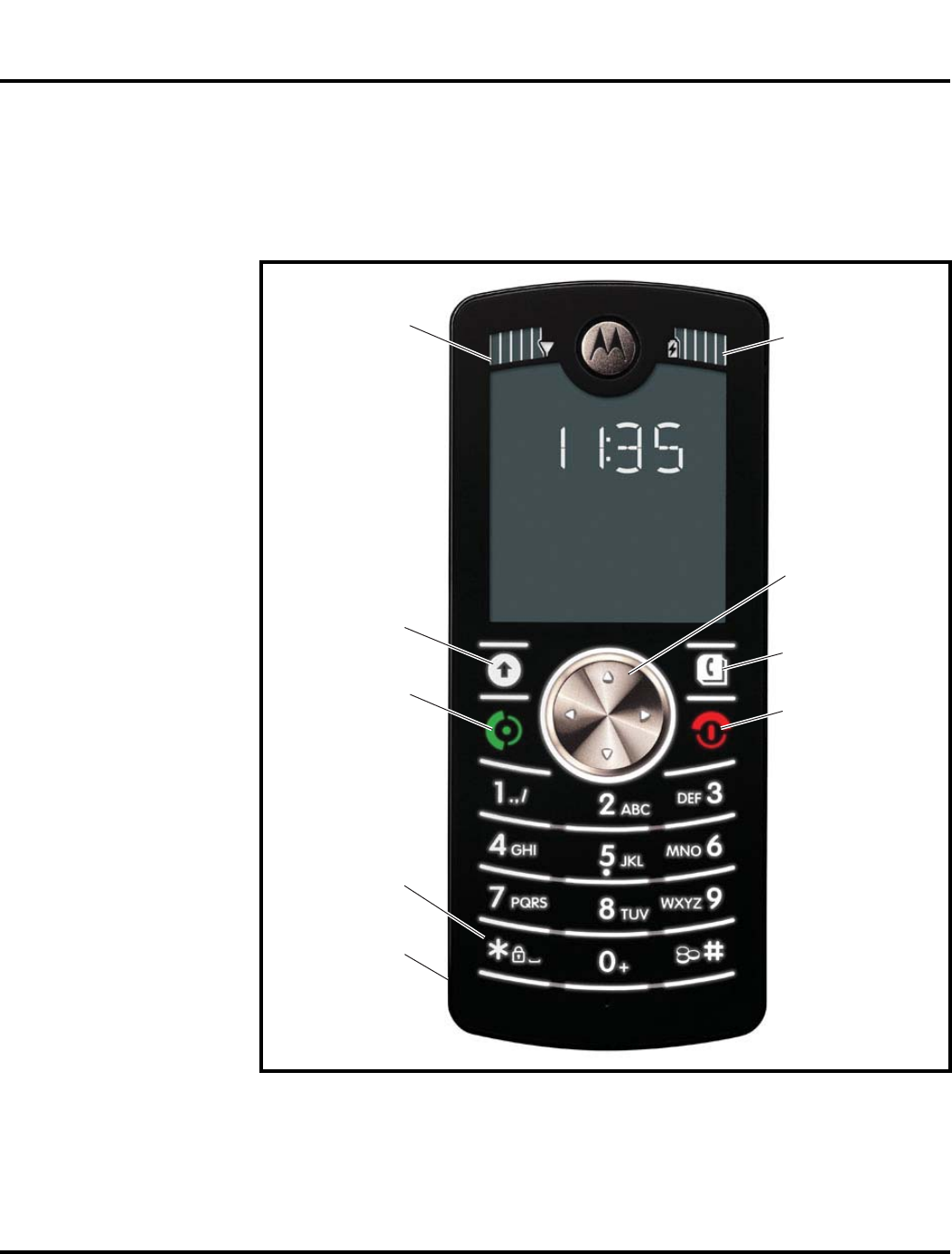
Controls, Indicators, and Input/Output (I/O) Connectors
The F3 controls are located on the front of the device, as shown in Figure 1.
061556o
Figure 1. Telephone Controls and Indicators
Signal
Strength Battery
Strength
Phone book
Turn phone on
and off,
hang up,
exit menus.
Navigation pad
Action Key
Make and
answer calls
Lock and
unlock keypad
Headset and
Phone charge
connector
6809505A65-A October 27, 2006 13
Level 1 and 2 Service Manual General Operation
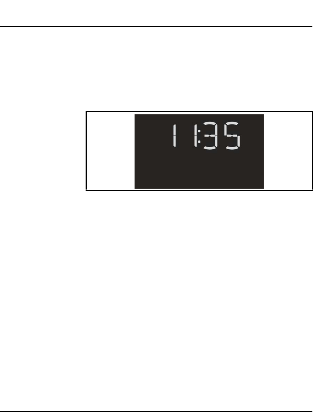
Electrophoretic Display (EPD)
The large display supports extra large characters for easy readability as well as
dedicated space for status and action icons.
Figure 2 shows the main screen display.
Battery Information
Battery Charge Indicator
The telephone displays a battery charge indicator icon in the idle screen to indicate
the battery charge level. The gauge shows five levels: 100%, 60%, 40%, 20%, and
Low Battery.
Battery Removal
Removing the battery causes the device to immediately shut down, and any pending
work (partially entered phone book entries or outgoing messages, for example) is
lost. Any text or image displayed on the screen at the time the battery is removed,
will remain visible on the screen. The screen will refresh as soon as it is turned on
again.
➧
Whether a phone displays all indicators depends on the programming and services
to which the user subscribes.
061557o
Figure 2. Main Screen Display
E
All batteries can cause property damage and/or bodily injury, such as burns if a
conductive material, such as jewelry, keys, or beaded chains touch exposed termi-
nals. The conductive material may complete an electrical circuit (short circuit) and
become quite hot. Exercise care in handling any charged battery, particularly when
placing it inside a pocket, purse, or other container with metal objects.
G
If the battery is removed while receiving a message, the message will be lost.
14 October 27, 2006 6809505A65-A
General Operation MOTOFONE F3
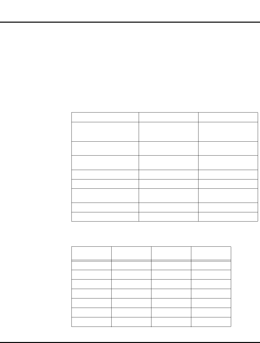
Battery Date Code
The battery date code is a 15 position alphanumeric code that provides backend
manufacture site information, year and week of manufacture date, cell type and
vendor information.
The battery date code is used for cell phone batteries that were manufactured
beginning in March 2003. The following paragraphs provide more detail about the
battery date code.
1. Backend Pack Manufacturing Site (first position of battery code)
2. Cell code and vendor (second and third position of battery code):
2 alpha characters.
➧
To ensure proper memory retention, turn the phone OFF before removing the
battery.
A = Motorola Penang J= ESG, Chihuahua S = T.D.I Scotland
B = T.D.I. Mexico K= T.D.I. Romeoville T = T.D.I Downers
Grove
T = TWS
C = Motorola China L = Motorola
Lawrenceville U = T.D.I. Hungary
D = T.D.I. Shanghai, China M =TDI, Malaysia
M = J Power
V =
E = ESG, Evadin, Brazil N = TDI, Manau, Brazil W = ESG, Sung Woo
F = ESG, Propower, Korea
O =
X = ESG, Foxlink, China
G = P = Intesys Arizona Y = P&K (G.E.T.)
Systems, Korea
H = Motorola Harvard
Q = Z =
I = Motorola lreland
R = Foxlink, Tianjin
Cell Reference
Designator
Vendor Size Part Number
IA A&TB 6.6x30x48 LGQ633048C
1B A&TB 6.6x30x48 LGQ633048D
1C A&TB 6.6x30x47.2 LGQ633048P
1D A&TB 8.8x34x48 LGQ863448C
1E A&TB 8.8x34x47.3 LGQ8634481-1
1F A&TB 18x65 LGR18650E
IG A&TB 7.5x14.5x48 TH750F5
6809505A65-A October 27, 2006 15
Level 1 and 2 Service Manual General Operation
1H A&TB 10.5x43.6 TH550AAA
3F Toshiba 7.5x14.5x48 TH900F5
3G Gold Peak 1/3A GPZSAFK
3H Toshiba 4.4x34x56 LA8423456A
3J Saft AA VHAA1200
3K Maxell 5.5x30x48 ICP053048G
3L NEC-Moli 6.7x30x47.3 MK11-2293
3M Mitsubishi 4.4x34x56 Lipmo001
3N Toshiba 6.6x34x50 LGQ633450R
3P Panasonic 6x34x50 CGP34506
3R Toshiba 3.9x34x56 LAB363456A
3S NEC-Moli 6.5x22x65 MK11-2300
3T BYD 6.6*9.8x47.9 LP063048A
3U* Panasonic LL-AAAA HHR70QAB4
3V Sanyo (Toshiba) 6mm NiMH THF6M
3W LG Chemical 6x30x48 ICP633048
3X BYD 5.4x30.1x48.2 LP053048A
3Y BYD 6x34x50 LPO53048A
3Z* Panasonic 6.2x35.2x16. HF6OSS
4A Peacebay-
Manual
6mm NiMH F6MG
4B BYD 4x30x48 F6MG
4C Peacebay-Auto 6.4x16.34 F6MP
4D Sanyo 6mm NiMH HFC1U
4E BYD 8x3 x47.5 LP083448SH
4F Sony 34x67 UP423467A4H
4G LG Chemical 8.6x34x48 ICP863448
4H LG Chemical 6.3x 34x50 ICP633450
4J* BYD 4x30x41 LP043O41A
4K GS Melcotec 4.6x29.5x41 LP423041A
4L LG Chemical 4.2x30x48 ICP423048
Cell Reference
Designator
Vendor Size Part Number
16 October 27, 2006 6809505A65-A
General Operation MOTOFONE F3
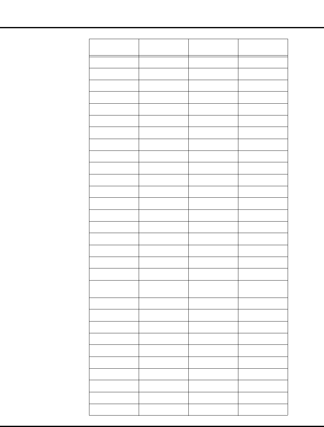
3. Cell date code (fourth fifth and sixth position of battery code) consisting of
characters as stated on cell pack by cell manufacturer. If a 3 digit code is not
used, place a period (.) in the sixth position.
4. Protection Circuit Module (PCM) code (seventh and eighth positions of battery
code) FF = 0164086T01
5. Year of battery manufacture (ninth position of battery code)
6. Week of manufacture (tenth and eleventh positions of battery code).
7. Front end corepack manufacturing site (twelfth position of battery code (see
step 1)).
Example of a battery date code: A1V90311JCCC...
position 1 = A = Motorola Penang.t (Backend Pack)
position 2 & 3 = 1V = Panasonic, AAA, HHR55B2
position 4, 5 & 6 = 903 = cell date code (from manufacturer)
position 7 & 8 = 11 = (TBD by supplier.Example: Line one of the first shift.)
position 9 = J = 1999 = Year of battery pack manufacture
position 10 & 11 = CC = week twenty two. (backend pack)
4M Toshiba 5.5x30x48 LGQ553048U
4N Sanyo 3.8x34x50 UF383450P
4P Toshiba 4.4x34x50 LGQ443450U
4R Toshiba 4.4x30x48 LGQ443048U
4S Lishen 06x30x48 LP0601AE
4T Panasonic AAAALL HHR70QAB4
8E NEC S14 - ICP043443B(-M)
8L Maxwell L08 - ICP463443ARM
1990 = A 1997 = H 2004 = O 2011 = V
1991 = B 1998 = I 2005 = P 2012 = W
1992 = C 1999 = J 2006 = Q 2013 = X
1993 = D 2000 = K 2007 = R 2014 = Y
1994 = E 2001 = L 2008 = S 2015 = Z
1995 = F 2002 = M 2009 = T
1996 = G 2003 = N 2010 = U
A=0 C=2 E=4 G=6 I=8
B=1 D=3 F=5 H=7 J=9
Cell Reference
Designator
Vendor Size Part Number
6809505A65-A October 27, 2006 17
Level 1 and 2 Service Manual General Operation
position 12 = C = Motorola, China. (Frontend Core Pack)
position 13, 14 & 15 = placeholders (...) to indicate pack has not been relabeled.
8. Re-label position (thirteenth position of battery code). A period (.) is to be added
if not relabeled. If relabeled, add the original date code year per step 5.
9. Line & shift manufactured (optional)/relabel (Fourteenth & Fifteenth position
of battery code) If not relabeled, consists of a two character combination either
alpha or numeric to be determined by the cell pack manufacturer for repre-
senting the line and shift. All unused positions shall be marked with a period
(.). If relabeled, consists of the original date code week positions per step 6."
10. Batteries sold in China have an additional character date code:
Example: YYYYMMDDABCXXXX
Where YYYYMMDD is the actual battery manufacturing date
A is the line number
B is the shift number (A,C is day shift; B, D is night shift)
C is a serial number from A to Z
XXXX is a sequence number
11. Embedded battery packs use a 6 character date code:
Position 1 is the manufacturing site:
Position 2 and 3 is cell code and vendor. See step 2.
Position 4, 5, and 6 is cell date code (year and week). See steps 5 and 6.
Operation
For detailed operating instructions, refer to the appropriate User Guide listed in
the Related Publications section toward the end of this manual.
Manufacturing Site Code
BYD a
ESG b
GSMT China c
GSMT Japan d
LG China e
LG Japan f
Maxell China g
Maxell Japan h
TDI i
Toshiba China j
Toshiba Japan k

18 October 27, 2006 6809505A65-A
General Operation MOTOFONE F3
6809505A65-A October 27, 2006 23
Level 1 and 2 Service Manual Tools and Test Equipment
Tools and Test Equipment
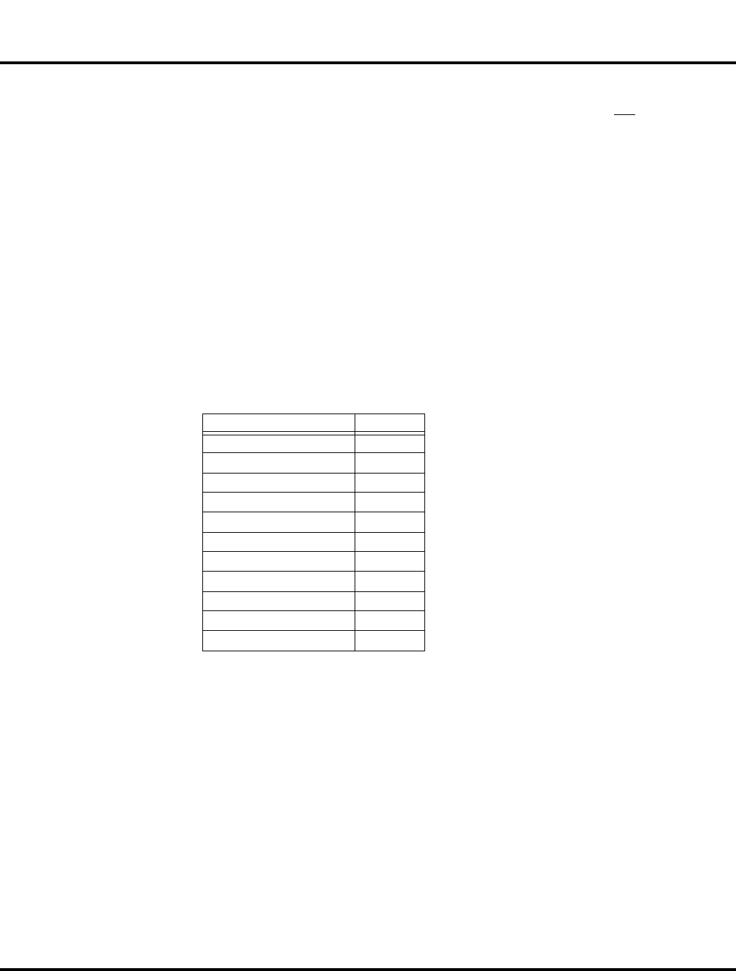
Table 1 lists the tools and test equipment used on F3 telephones. Use either the
listed items or equivalents.
Table 1. General Test Equipment and Tools
Motorola
Part Number
1
Description Application
See Table 5 Charger Used to charge battery and to power phone
0180386A82
Antistatic Mat Kit (includes 66-80387A95 antistatic
mat, 66-80334B36 ground cord, and 42-80385A59
wrist band)
Provides protection from damage to phone caused
by electrostatic discharge (ESD)
8102430Z04 GSM / DCS / PCS Test SIM Used to enable manual test mode
6680388B67 Disassembly tool, plastic with flat and pointed
ends (manual opening tool) Used during assembly/disassembly of phone
6680388B01 Tweezers, plastic Used during assembly/disassembly
RSX4043-A Torque Driver Used to remove and replace screws
—Torque Driver Bit T-5 Plus, Apex 440-6IP Torx Plus
or equivalent Used with torque driver
Size 0 Phillips head driver Used to remove transceiver board screws
HP34401A
2
Digital Multimeter Used to measure battery voltage
1. To order in North America, contact Motorola Aftermarket and Accessories Division (AAD) by phone at (800) 422-4210 or
FAX (800) 622-6210; Internationally, AAD can be reached by calling (847) 538-8023 or faxing (847) 576-3023.
2. Not available from Motorola. To order, contact Hewlett Packard at (800) 452-4844.
1 and 2
MOTOFONE F3
6809505A65-A

24 October 27, 2006 6809505A65-A
Disassembly MOTOFONE F3
Disassembly
This section describes how to disassemble a F3 telephone. Tools and equipment
used are listed in Table 1, preceding.
G
Many of the integrated devices used in this equipment are vulnerable to damage
from electrostatic discharge (ESD). Ensure adequate static protection is in place
when handling, shipping, and servicing the internal components of this equipment.
G
Avoid stressing the plastic in any way to avoid damage to either the plastic or
internal components.
6809505A65-A October 27, 2006 25
Level 1 and 2 Service Manual Disassembly
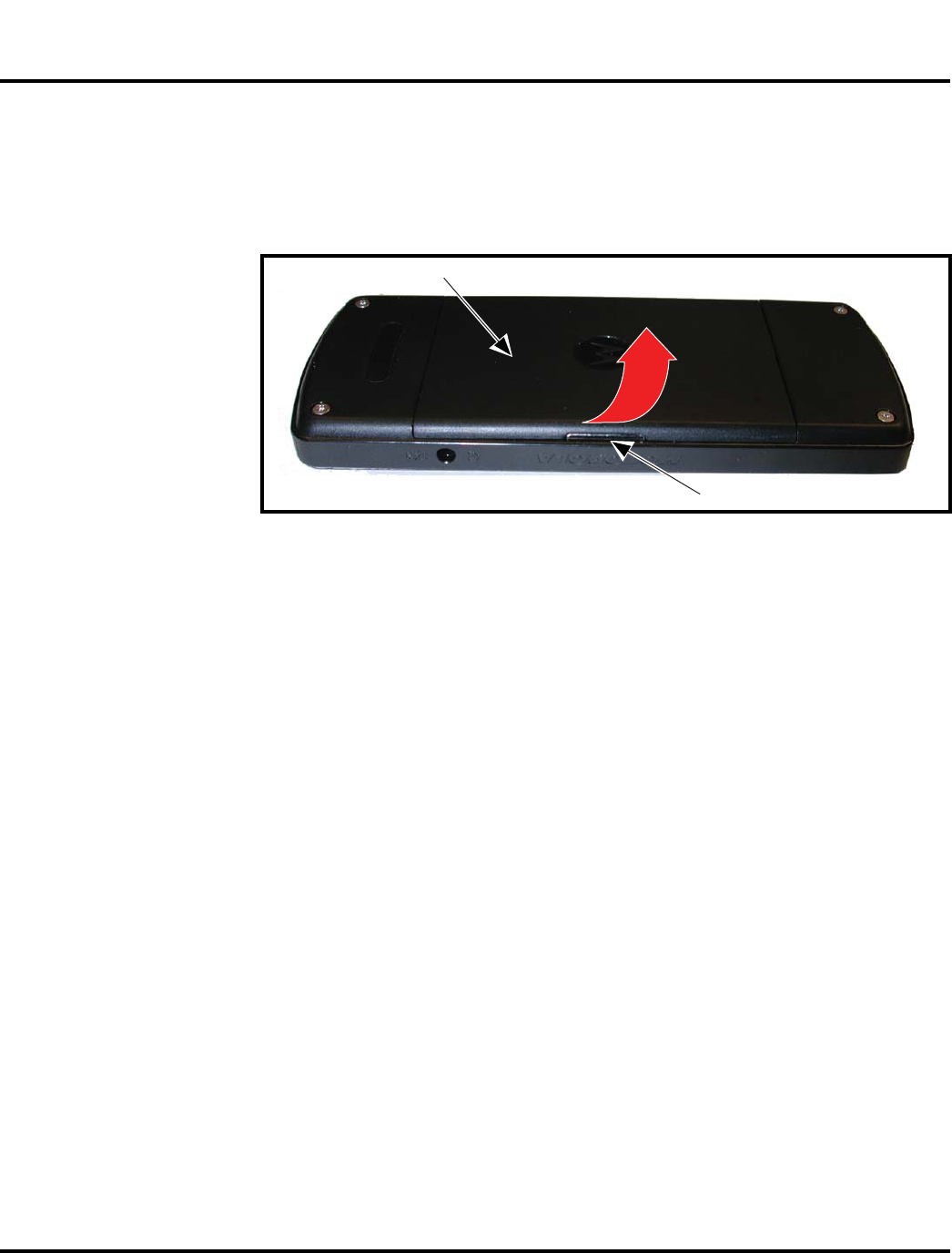
Removing and Replacing the Battery Cover
1. Ensure the phone is turned off.
2. Press down on the battery cover latch on the back of the phone and lift it up in
the direction of the arrow, then lift the battery cover away from the phone (see
Figure 3).
3. To replace, align the battery cover to the back of the phone.
4. Gently press the battery cover into position until the battery cover snaps into
place.
061558o
Figure 3. Removing the Battery Cover
Battery cover
Battery cover latch
26 October 27, 2006 6809505A65-A
Disassembly MOTOFONE F3
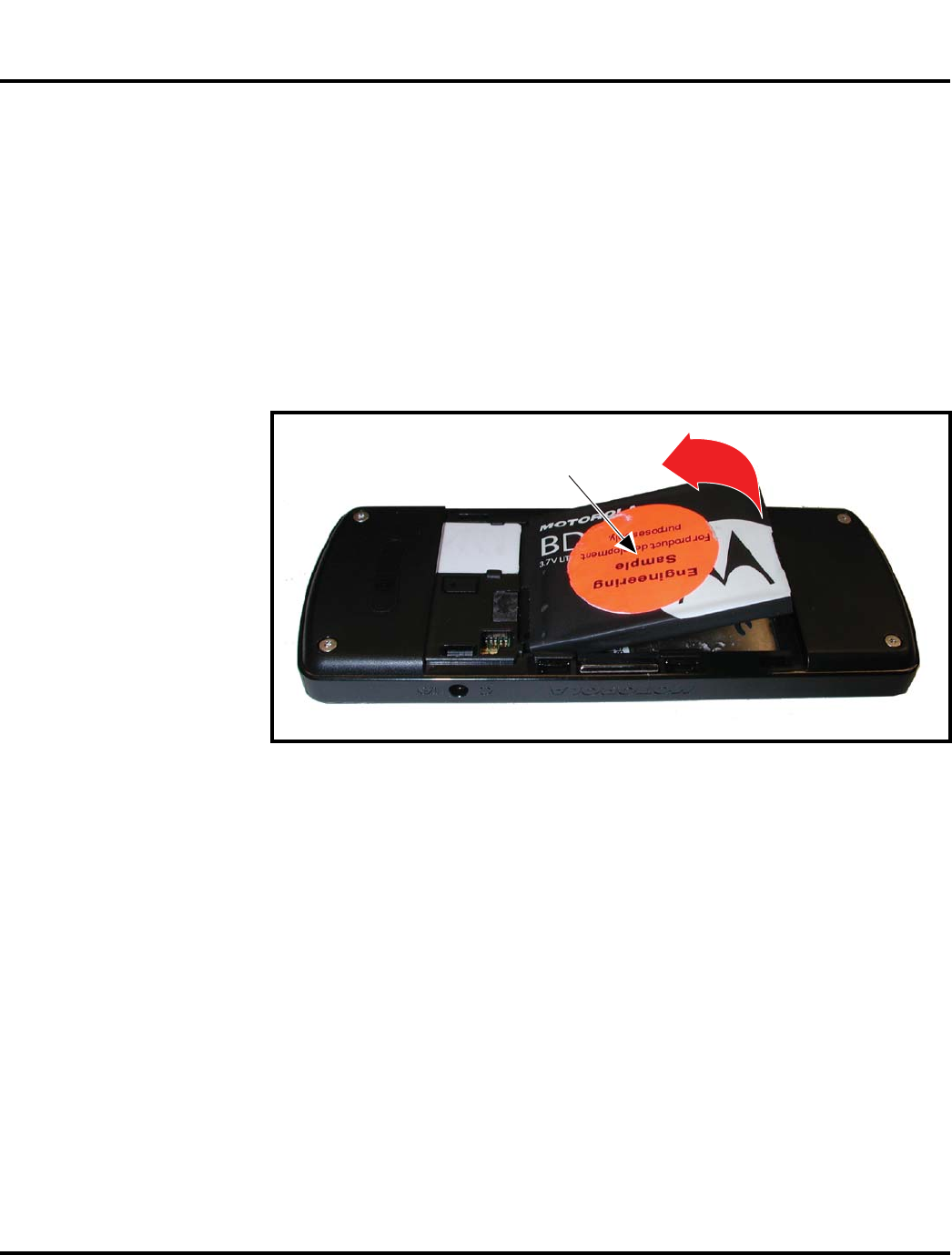
Removing and Replacing the Battery
Before handling the battery, please observe the battery cautions listed below.
1. Remove the battery cover, as described in the procedures.
2. Lift the end of the battery, as shown in Figure 4.
3. Lift the battery out of the battery compartment.
4. To replace, insert the bottom end of the battery into the battery compartment
with contacts facing downward.
5. Press the top of the battery into the battery compartment.
6. Replace the battery cover as described in the procedures.
G
Do not handle batteries with wet or sweaty hands.
Do not short the positive or negative terminals.
Non conductive tweezers or grasping tools are to be used for battery connector
manipulation, assembly, and disassembly.
061559o
Figure 4. Removing and Replacing the Battery
E
There is a danger of explosion if the Lithium ion battery is replaced incorrectly.
Replace only with the same type of battery or equivalent as recommended by the
battery manufacturer. Dispose of used batteries according to the manufacturer’s
instructions.
Battery
6809505A65-A October 27, 2006 27
Level 1 and 2 Service Manual Disassembly
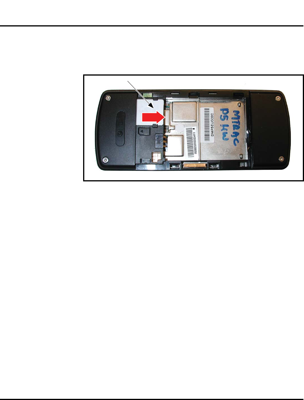
Removing and Replacing the Subscriber Identity Module (SIM)
1. Remove the battery cover, and battery as described in the procedures.
2. Remove the SIM from the phone by sliding it in the direction indicated, as
shown in Figure 5.
3. To replace, carefully slide the SIM all the way into the SIM holder. Observe
the notched corner when inserting the SIM.
4. Replace the battery and the battery cover as described in the procedures.
061560o
Figure 5. Removing the SIM
SIM
28 October 27, 2006 6809505A65-A
Disassembly MOTOFONE F3
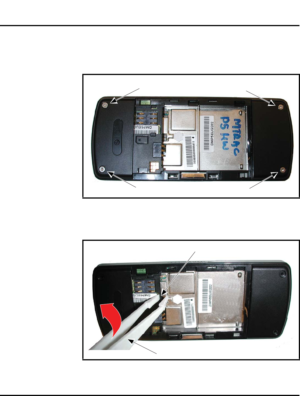
Removing and Replacing the Rear Housing
1. Remove the battery cover, battery, SIM, as described in the procedures.
2. Use a T5 driver to remove 4 housing screws (see Figure 6). Set the screws aside
for reuse.
3. Use the plastic tweezers to release the housing latch next to the battery
contacts. under the rear housing (see Figure 7).
061561o
Figure 6. Housing Screw Locations
061604o
Figure 7. Releasing the Housing Latch
Housing screw
Housing screw
Housing screw
Housing screw
Plastic tweezers
Housing latch
6809505A65-A October 27, 2006 29
Level 1 and 2 Service Manual Disassembly
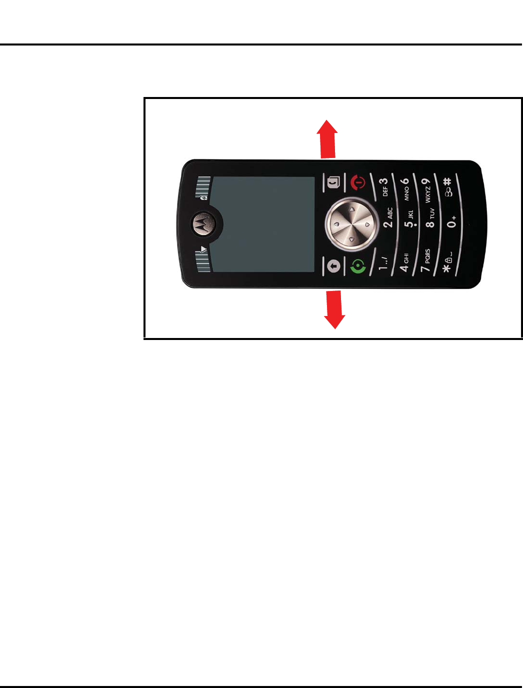
4. Apply outward pressure to the left and right sides of the battery compartment
to release the housing latches on the sides of the phone (see Figure 8).
5. Carefully lift the rear housing from the phone.
6. To replace, align the rear housing to the phone.
7. Lower the rear housing onto the phone.
8. Gently press the rear housing onto the phone to engage the latches on the sides
of the phone.
9. Engage the housing latch in the center of the phone by gently pressing on the
rear housing near the battery contacts.
10. Insert and tighten the 4 housing screws using the T5 driver. Tighten to 8.9Ncm
+/- 0.55. Do not overtighten.
11. Replace the SIM, battery, battery cover as described in the procedures.
061562o
Figure 8. Releasing the Side Housing Latches
30 October 27, 2006 6809505A65-A
Disassembly MOTOFONE F3
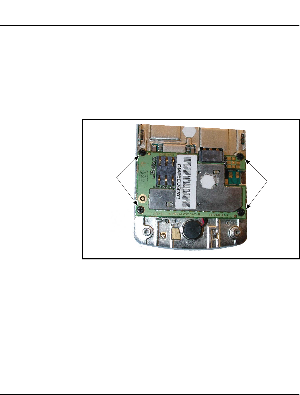
Removing and Replacing the Transceiver Board Assembly
1. Remove the battery cover, battery, SIM, rear housing, as described in the
procedures.
2. Use a size 0 Phillips screwdriver to remove the 4 main board screws (see
Figure 9).
G
This product contains static-sensitive devices. Use anti-static handling procedures
to prevent electrostatic discharge (ESD) and component damage.
061563o
Figure 9. Removing the Main Board Screws
Main board
screwsMain board
screws
6809505A65-A October 27, 2006 31
Level 1 and 2 Service Manual Disassembly
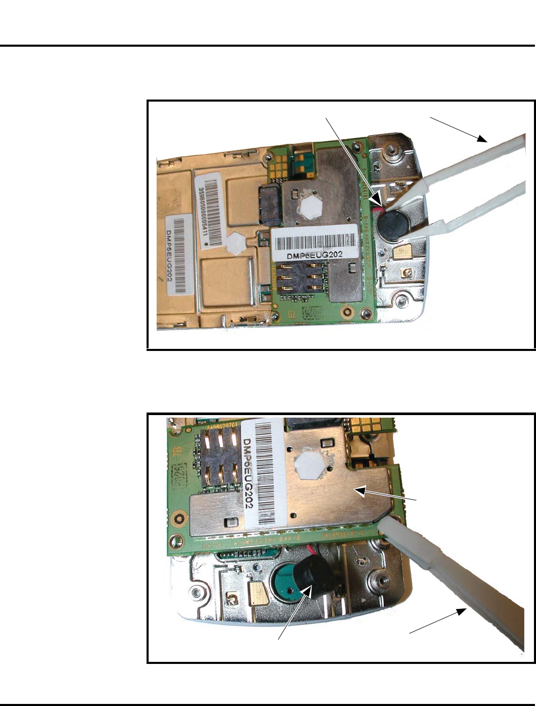
3. Use the plastic tweezers to lift the microphone assembly out of its place on the
chassis. Avoid damage to the microphone wires.
4. Carefully lift the main board from the front chassis.
061564o
Figure 10. Removing the Microphone Assembly
061565o
Figure 11. Removing the Transceiver Board Assembly
Microphone assembly Plastic tweezers
Main board
Plastic tweezers
Microphone assembly

32 October 27, 2006 6809505A65-A
Disassembly MOTOFONE F3
5. To replace, align the main board assembly to the chassis.
6. Insert and tighten the 4 main board screws with the size 0 Phillips screwdriver.
7. Place the microphone assembly into the opening in the chassis. Avoid damage
to the microphone wires.
8. Replace the rear housing, SIM, battery, and battery cover as described in the
procedures.
6809505A65-A October 27, 2006 33
Level 1 and 2 Service Manual Disassembly
Removing the Keypad Lens
1. Remove the battery cover, battery, SIM, rear housing, as described in the
procedures.
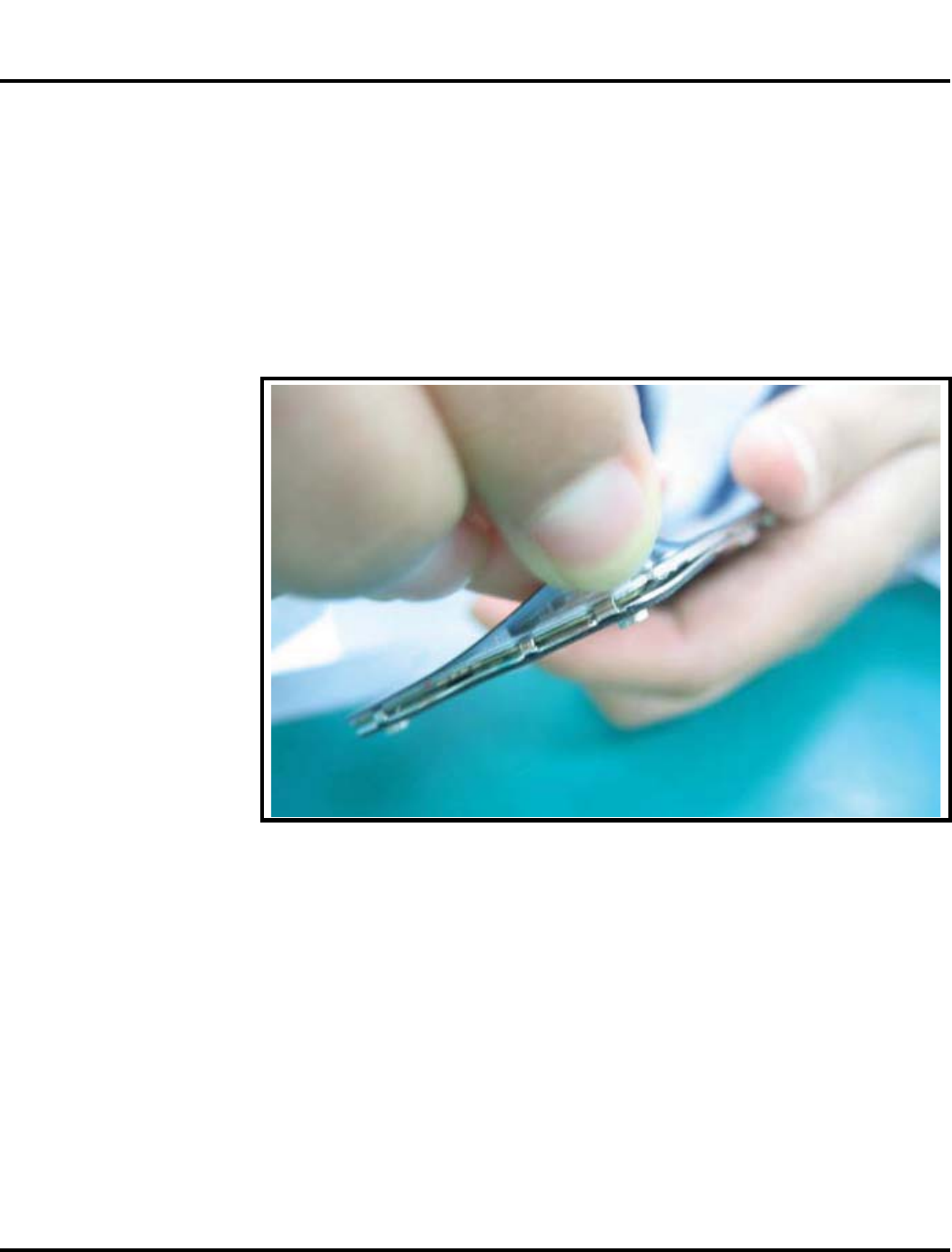
2. Remove the keypad lens by carefully lifting one corner of the keypad lens by
hand and peeling the entire keypad lens away from the chassis (see Figure 12).
G
This product contains static-sensitive devices. Use anti-static handling procedures
to prevent electrostatic discharge (ESD) and component damage.
061614o
Figure 12. Removing the Keypad Lens
34 October 27, 2006 6809505A65-A
Subscriber Identity Module (SIM) and Identification Label MOTOFONE F3
Subscriber Identity Module (SIM) and Identification Label
SIM
A SIM is required to access the existing local GSM network, or remote networks
when traveling (if a roaming agreement has been made with the provider).
The SIM card contains:
• All the data necessary to access GSM services
• The ability to store user information such as phone numbers
• All information required by the network provider to provide access to the
network
Identification
Each Motorola GSM phone is labeled with a variety of identifying numbers. The
following information describes the current identifying labels.
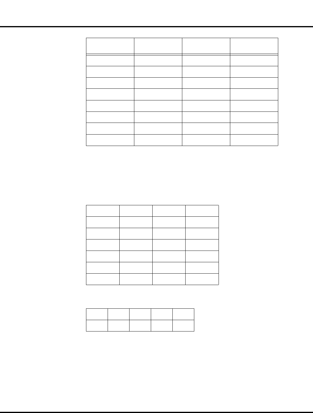
Mechanical Serial Number (MSN)
The MSN is an individual unit identity number and remains with the unit through-
out its life.
The MSN can be used to log and track a phone on Motorola's Service Center
Database.
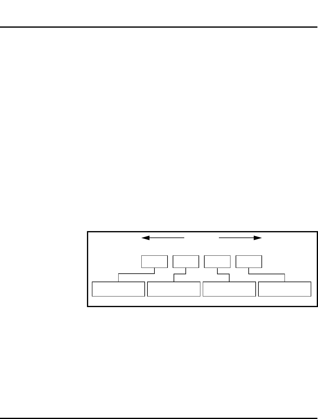
The MSN is divided into 4 sections, as shown in Figure 13.
000807a
Figure 13. MSN label breakdown
MSN 10 Digits
3 Digits 1 Digit 2 Digits 4 Digits
APC DC DC SNR
Account Product Code
i.e. StarTAC Phone130
Distribution Center
i.e. Easter Inch
Date Code: Year and
Month of Shipment
Unit's individual serial
number
TM
6809505A65-A October 27, 2006 35
Level 1 and 2 Service Manual Subscriber Identity Module (SIM) and Identification
Label
International Mobile Station Equipment Identity (IMEI)
The International Mobile station Equipment Identity (IMEI) number is an
individual number unique to the PCB and is stored within the unit's memory.
The IMEI uniquely identifies an individual mobile station and thereby provides a
means for controlling access to GSM networks based on mobile station types or
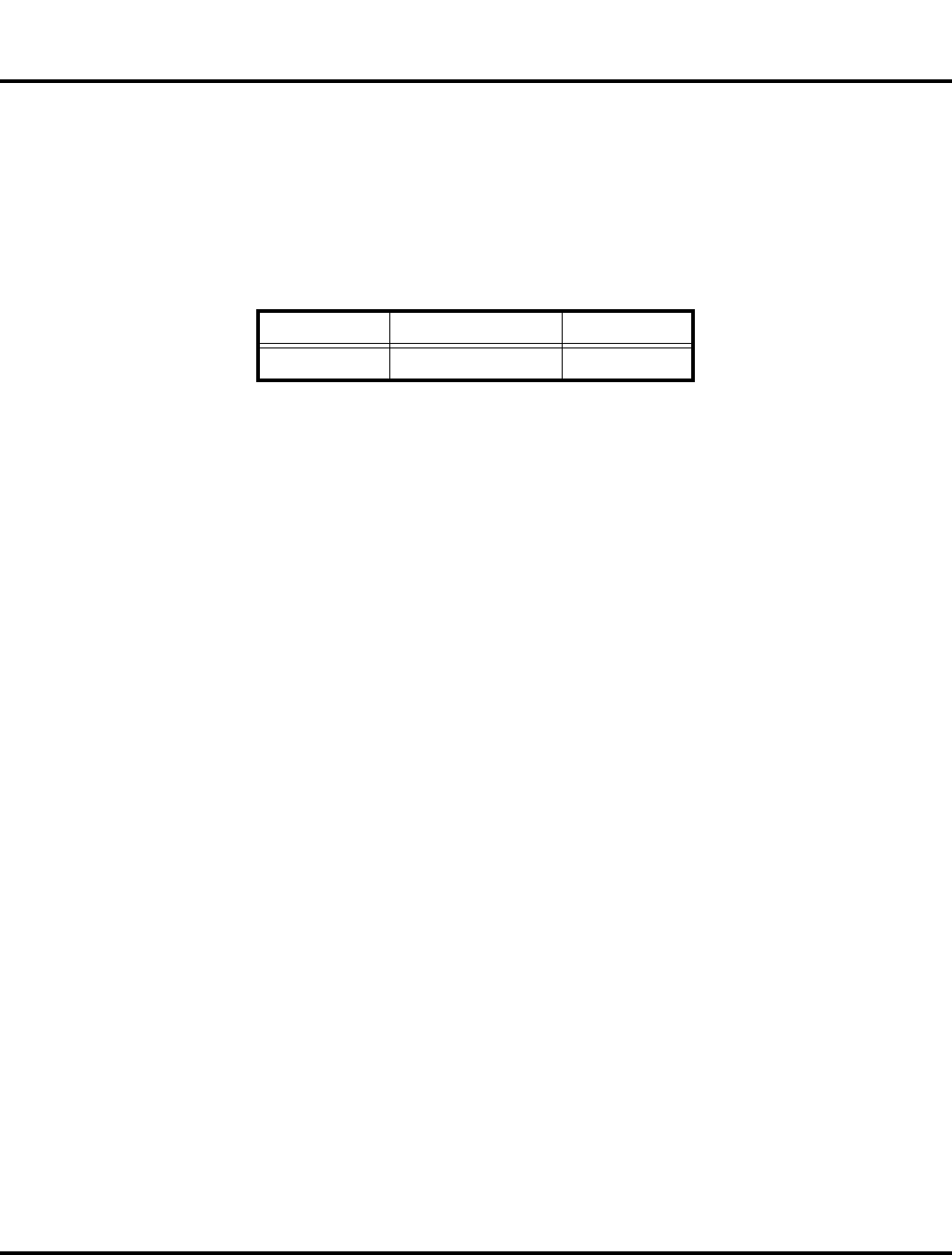
individual units. The full IMEI structure is listed in Table 2.
Where
TAC Type Allocation Code, formerly known as Type Approval Code
NN Reporting body identifier
XXXXXX Type Identifier
ZZZZZZ Individual unit serial number
APhase 1 = 0.
Phase 2 = check digit defined as a function of all other IMEI digits
Other label number configurations present are:
•TRANSCEIVER NUMBER: Identifies the product type. Normally the SWF
number. (i.e. V100).
•PACKAGE NUMBER: Identifies the equipment type, mode, and language in
which the product is shipped.
Table 2. IMEI Number Breakdown
TAC Serial Number Check Digit
NNXXXXXX ZZZZZZ A

36 October 27, 2006 6809505A65-A
Troubleshooting Chart MOTOFONE F3
Troubleshooting Chart
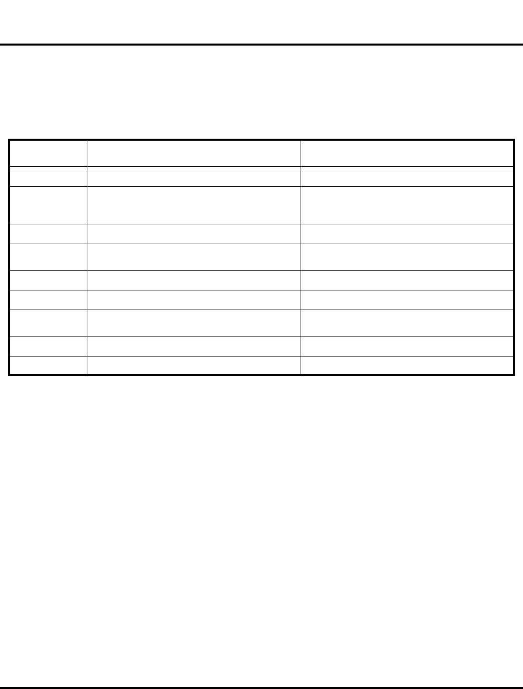
Table 3. Level 1 and 2 Troubleshooting Chart
Symptom Probable Cause Verification And Remedy
1. Telephone will not turn on or stay on. a) Battery either discharged or
defective.
Measure the voltage at TP_BATT+ with battery
attached. If voltage is below 3.0V, attach a
charger to the phone and ensure that the phone
is charging. If the phone does not charge,
change the battery and repeat the measurement
charging procedure. If the phone still does not
turn on, proceed to b).
b) Transceiver board defective. Forward unit to a level 3 service center for
replacement.
2. Telephone exhibits poor reception or
erratic operation such as calls frequently
dropping or weak or distorted audio.
a) Speaker/antenna assembly
defective
Check connection between the speaker/antenna
assembly and the transceiver board. If the
contact is intermittent visually, replace with a
known good speaker/antenna assembly. If the
fault is still present, proceed to b.
b) Transceiver board defective. Forward unit to a level 3 service center for
replacement.
3. No display. a) Connections between transceiver
and display faulty.
Check connections between transceiver board
and display. If display still does not come up,
proceed to b.
b) Display module defective.
Replace with a known good display module.
Verify that the fault has been cleared with the
new display module and reassemble the unit.
4. Incoming call alert transducer audio
distorted or volume is too low. a) Faulty antenna/speaker assembly.
Replace the antenna/speaker assembly with a
known good antenna/speaker assembly. If the
problem goes away, replace with a new antenna/
speaker assembly. Else proceed to b.
b) Transceiver board defective Forward unit to a level 3 service center for
replacement.
5. Telephone transmit audio is weak.
(usually indicated by called parties
complaining of difficulty in hearing voice).
a) Microphone defective. Replace the microphone as described in the
procedures. If fault is not cleared, proceed to b.
b) Transceiver board defective Forward unit to a level 3 service center for
replacement.
6. Receive audio from earpiece speaker is
weak or distorted.
a) Contacts between earpiece
speaker and transceiver board faulty.
Replace the earpiece speaker with a known
good one. Reassemble with a new front housing
if the fault goes away. If the fault is still present,
proceed to b.
b) Transceiver board defective. Forward unit to a level 3 service center for
replacement.
7. Telephone will not recognize or accept
SIM card. a) SIM card defective.
Check the SIM card contacts for dirt. Clean if
necessary, and check if fault has been cleared.
If the contacts are clean, insert a known good
SIM card into the telephone. Power up the unit
and confirm that the card has been accepted. If
the fault goes away, replace the defective SIM
card. If the SIM card is not at fault, proceed to b.
b) Transceiver board defective Forward unit to a level 3 service center for
replacement.
8. No or weak audio when using headset. a) Headset plug not pushed in fully. Ensure the headset plug is fully seated in the
jack.

6809505A65-A October 27, 2006 37
Level 1 and 2 Service Manual Part Numbers
Programming: Software Upgrade and Flexing
Contact your local technical support engineer for information about equipment and
procedures for flashing and flexing.
Part Numbers
The following section provides a reference for the parts associated with
F3 telephones.
b) Faulty jack on rear housing.
Replace the rear housing. Verify that the fault
has been cleared and reassemble the unit with
the new rear housing.
Table 3. Level 1 and 2 Troubleshooting Chart (Continued)
Symptom Probable Cause Verification And Remedy
38 October 27, 2006 6809505A65-A
Part Numbers MOTOFONE F3
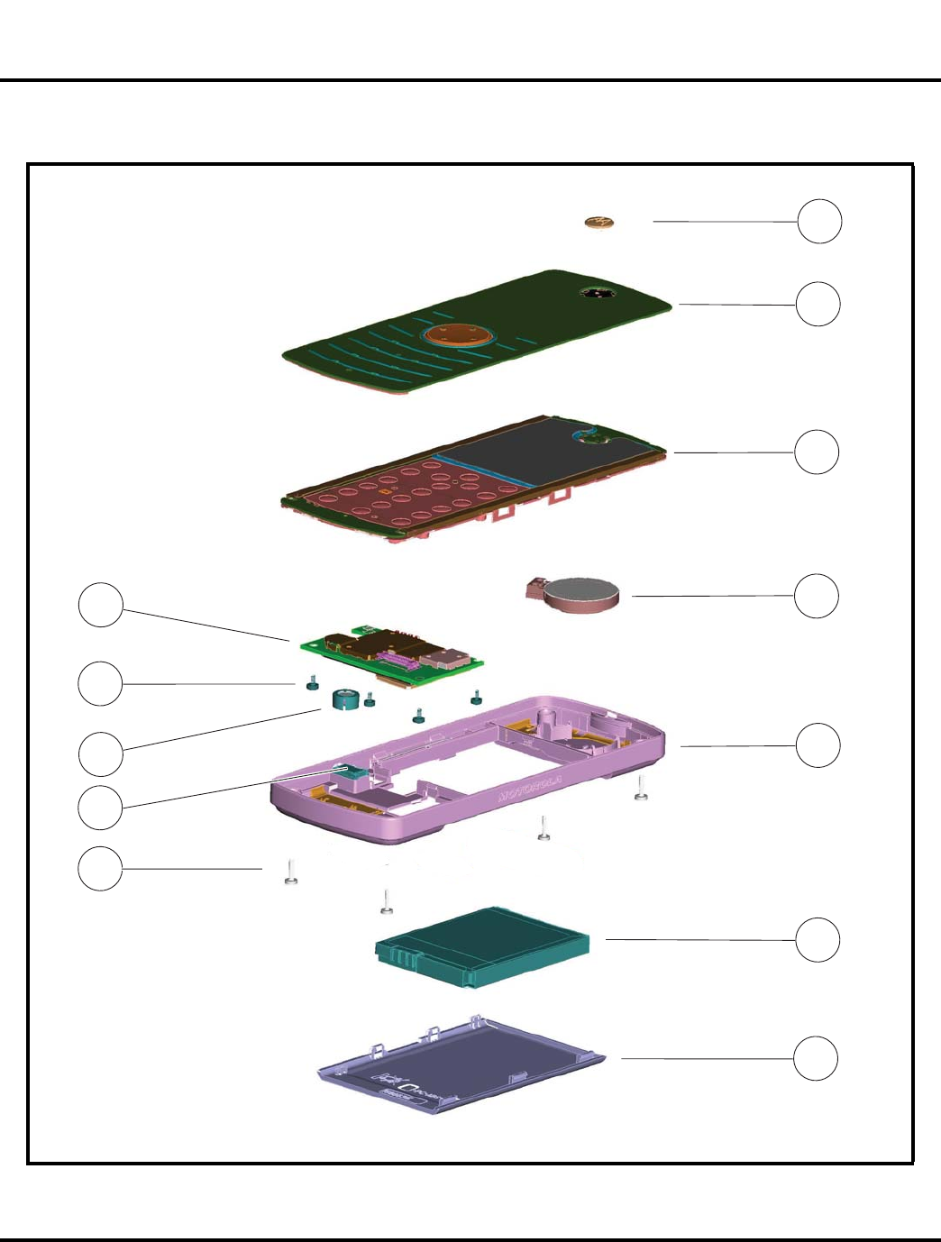
Exploded View Diagram
061549o
Figure 14. Exploded View Diagram
1
2
3
4
5
6
7
8
10
10
12
12
11
11
9
6809505A65-A October 27, 2006 39
Level 1 and 2 Service Manual Part Numbers
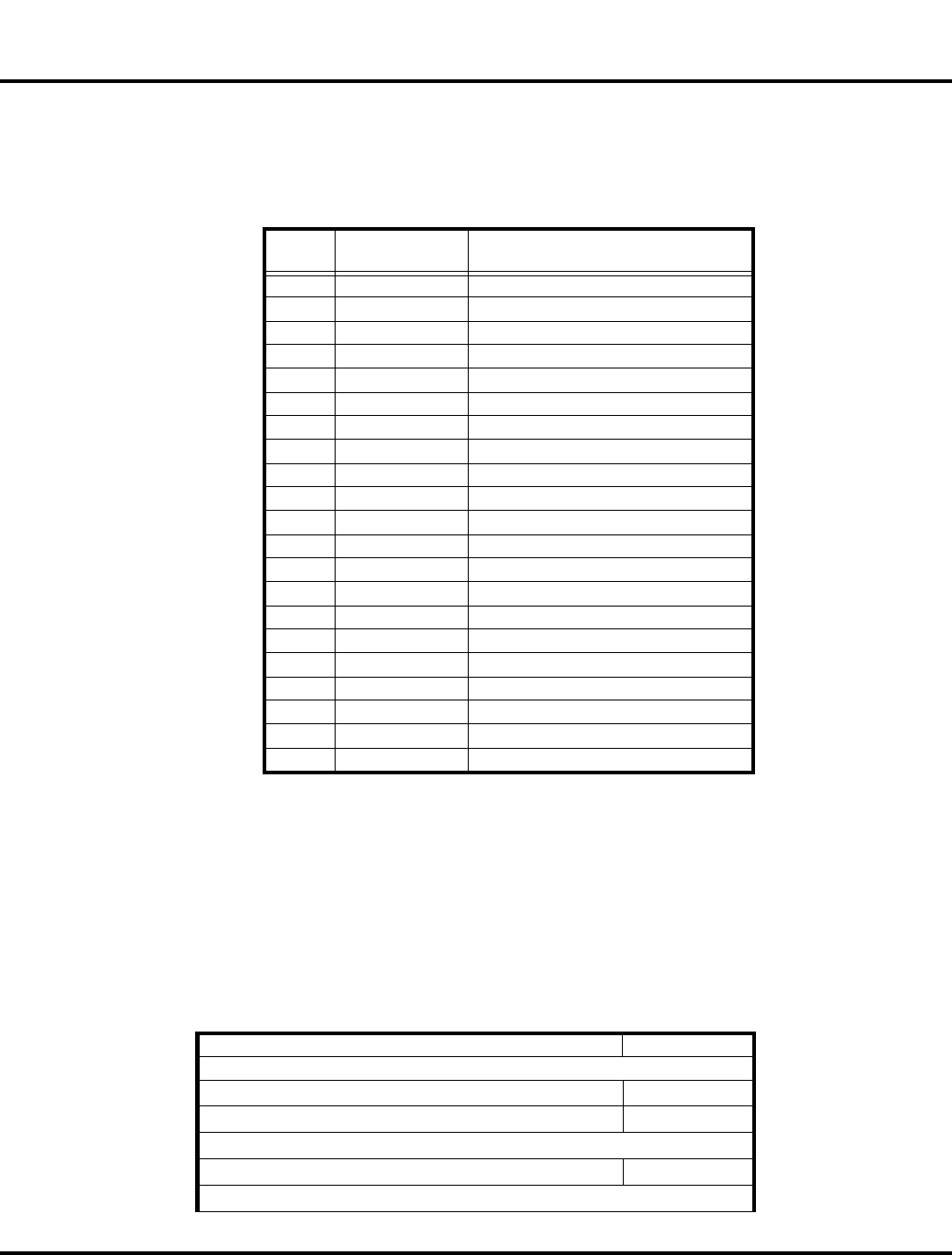
Exploded View Parts List
Part numbers are provided only for reference. Contact your local Motorola parts
organization for current part number information
.
For information on ordering parts please contact EMEA at +49 461 803 1404.
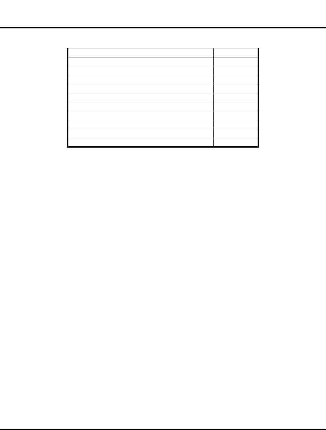
Accessories
Table 4. Exploded View Parts List
Item
Number
Motorola Part
Number Description
1 3388674Z01 Medallion
2 Keypad Lens assembly
2a 0188045Z06 US/Euro GREY
2b 0188045Z14 US/Euro RED
2c 0188045Z15 US/Euro BLUE
3 Keypad PCB Assembly
CHLG4610 Euro Band
CHLG4617 US Band
4 5088767Z02 Speaker/Vibrator Transducer
5 Rear Housing Assembly
0164078T01 Euro Band
0164078T02 US Band
6 SNN5796 Battery Pack
7 1588631Z01 Battery Door
8 0388668Z01 Screw M1.4x6 (4pcs)
9 0988673Z05 DC/Headset Jack
10 5088694Z01 Mic Assembly
11 0388691Z01 Screw M1.4x2.6 (4pcs)
12 PWA, Main PCB Assembly
CHLG4614 Euro Band
CHLG4616 US Band
E
There is a danger of explosion if the Lithium ion battery pack is replaced incorrectly.
Replace only with the same type of battery or equivalent as recommended by the
battery manufacturer. Dispose of used batteries according to the manufacturer’s
instructions.
Table 5. Accessories
Accessory Description Kit Number
Audio & Connectivity
Mono Wired Headset (2.75mm barrel) SYN1839A
TTY Adapter SKN6242A
In-Vehicle Solutions
Vehicle Power Adapter
SYN1829A
Power Solutions
40 October 27, 2006 6809505A65-A
Part Numbers MOTOFONE F3
Battery SNN5796A
Travel charger (F3 only) - Argentina SPN5326A
Travel charger (F3 only) - Australia SPN5323A
Travel charger (F3 only) - BRAZIL SPN5320A
Travel charger (F3 only) - EURO SPN5324A
Travel charger (F3 only) - INDIA SPN5322A
Travel charger (F3 only)- MEXICO SPN5319A
Travel charger (F3 only) - PRC SPN5318A
Travel charger (F3 only) - TWN SPN5321A
Travel charger (F3 only) - UK/HK SPN5325A
Travel charger (F3 only) - US ENG SPN5317A
Table 5. Accessories (Continued)

6809505A65-A October 27, 2006 Index-1
Level 1 and 2 Service Manual Index
Index
A
antenna, removing and replacing
26
B
battery
charge indicator
13
function
13
battery cover, removing and replacing
25
battery, removing and replacing
26
C
Canadian Interference-Causing Equipment regulations
5
changes
product
5
copyrights
computer software
6
D
disassembly
24
E
Electrophoretic Display (EPD)
13
EPD
13
exploded view diagram
38
exploded view parts list
39
F
FCC rules
5
I
identification
international mobile station equipment identity
35
mechanical serial number
34
product
5
identification, labels
34
IMEI
35
Introduction
5
M
microphone, removing and replacing
34
MSN
34
N
names
product
5
O
operation
12
battery
13
controls, indicators, and I/O connectors
12
overview, product
11
P
part numbers
accessories
39
parts
exploded view diagram
38
exploded view parts list
39
replacement parts
37
product
changes
5
identification
5
names
5
product overview
11
features
11
R
Rear Housing, removing and replacing
28
regulatory agency compliance
5
removing
antenna
26
battery
13, 26
battery cover
25
microphone
34
Rear Housing
28
SIM
27
transceiver board
34
Transceiver Board Assembly
30
replacement parts
ordering
7
replacing
antenna
26
battery
26
battery cover
25
microphone
34
Rear Housing
28
SIM
27
transceiver board
34
Transceiver Board Assembly
30
S
1 and 2
Index
MOTOFONE F3
6809505A65-A

Index-2 October 27, 2006 6809505A65-A
Index MOTOFONE F3
serial number
mechanical
34
service manual
about
6
audience
6
conventions
7
scope
6
service policy
7
customer support
7
out of box failure
7
product support
7
shut down
upon battery removal
13
SIM, description
34
SIM, removing and replacing
27
specifications
9
subscriber identity module (SIM)
34
support
customer
7
product
7
T
test equipment
23
tools, disassembly
23
Transceiver Board Assembly, removing and replacing
30
transceiver board, removing and replacing
34
troubleshooting
troubleshooting chart
36
W
warranty service
7