Motorola Canopy Powerline Mu Users Manual ........................... User Guide
Powerline MU to the manual e67a5365-3479-4ccc-83ce-d2b0c1e4bc0d
2015-01-23
: Motorola Motorola-Canopy-Powerline-Mu-Users-Manual-271783 motorola-canopy-powerline-mu-users-manual-271783 motorola pdf
Open the PDF directly: View PDF ![]() .
.
Page Count: 112 [warning: Documents this large are best viewed by clicking the View PDF Link!]
- 1 ABOUT THIS USER GUIDE 8
- 2 OVERVIEW OF POWERLINE MU 11
- 2.2 Powerline MU Products 14
- 2.3 Ordering Equipment Plug Types 14
- 3 Planning the Powerline MU Network 15
- 3.4 Building Electrical Considerations 17
- 4 Installing Powerline MU 18
- 5 Hardware Installation 33
- 6 CONFIGURING THE POWERLINE MU GATEWAY 36
- 6.2 Configuration and Maintenance 38
- 6.3 Advanced 43
- 6.4 IP Address 51
- 6.5 Powerline 52
- 7 Powerline Modem 58
- 7.2 Powerline Modem Screen Map 59
- 7.3 Configuring the Powerline Modem 59
- 7.3.1 System Info 60
- 7.3.2 System Password 61
- 7.3.3 System Logs 62
- 7.3.4 Reset 63
- 7.3.5 Backup 64
- 7.3.6 Site Info 65
- 7.3.7 Advanced Packet Priority 66
- 7.3.8 Advanced Bandwidth Control 67
- 7.3.9 Advanced SNMP Configuration 68
- 7.3.10 Advanced SNMP Access Control 70
- 7.3.11 Operating Mode (Modem Repeater Function) 70
- 7.3.12 VLAN Configuration 72
- 7.4 IP Configuration 73
- 8 Legal and Regulatory Notices 79
- 8.3 Legal Notices 89
- 9 Additional Resources 92
- 10 History of Changes in This Document 93
- 11 Technical Specifications 94
- Appendix A International Electric Grid Plug Types 101
- Appendix B Signal Distances 110

Powerline MU User Guide
Powerline MU
User Guide
PowerlineMU-UG-en
Issue 4.0
August, 2007

Trademarks, Product Names, and Service Names
MOTOROLA, the stylized M Logo, Canopy and all other trademarks indicated as such
herein are registered trademarks of Motorola, Inc.® Reg. U.S. Pat & Tm. Office. All other
product or service names are the property of their respective owners.
© 2007 Motorola, Inc. All rights reserved.
http://www.motorola.com/canopy

Powerline MU
Page 3 of 112
TABLE OF CONTENTS
1 ABOUT THIS USER GUIDE.......................................................................................8
1.1 Becoming Familiar with This User Guide ........................................................... 8
1.2 Getting Additional Help...................................................................................... 9
1.3 Sending Feedback........................................................................................... 10
2 OVERVIEW OF POWERLINE MU............................................................................ 11
2.1 Powerline MU Features ................................................................................... 12
2.1.1 Security.............................................................................................................. 12
2.1.2 Bandwidth Management.................................................................................... 13
2.1.3 Network Operations........................................................................................... 13
2.2 Powerline MU Products ................................................................................... 14
2.3 Ordering Equipment Plug Types...................................................................... 14
3 Planning the Powerline MU Network ..................................................................... 15
3.1 Canopy Wireless .............................................................................................15
3.2 Powerline MU .................................................................................................. 15
3.3 Connecting the Canopy Network to the Gateway.............................................16
3.3.1 Ethernet from SM to Gateway........................................................................... 16
3.3.2 Ethernet from SM to Powerline MU Hybrid Adapter to Powerline MU Hybrid
Adapter to Gateway ........................................................................................................ 17
3.4 Building Electrical Considerations.................................................................... 17
3.4.1 Main Planning.................................................................................................... 17
3.4.2 Owners of Electrical Equipment ........................................................................ 17
3.4.3 Gateway Location.............................................................................................. 17
4 Installing Powerline MU.......................................................................................... 18
4.1 Two-Phase (Single-Phase) Installation............................................................ 21
4.2 Three-Phase Installation.................................................................................. 22
4.2.1 Mass Metered.................................................................................................... 23
4.2.2 Using a Panel Extender (multiple electrical panels).......................................... 24
4.2.3 Individually Metered .......................................................................................... 25
4.2.4 Multiple Transformer ......................................................................................... 30
5 Hardware Installation..............................................................................................33
5.1 Upgrading Firmware ........................................................................................33
5.2 Equipment Staging .......................................................................................... 33

Powerline MU
Page 4 of 112
5.3 Installation ....................................................................................................... 34
5.3.1 Mount the Gateway ........................................................................................... 34
5.3.2 Install Modems .................................................................................................. 35
6 CONFIGURING THE POWERLINE MU GATEWAY ................................................ 36
6.1 Connect to the Gateway .................................................................................. 36
6.1.1 User Interface Navigation tips ........................................................................... 37
6.2 Configuration and Maintenance ....................................................................... 38
6.2.1 System Information ........................................................................................... 38
6.2.2 Date and Time................................................................................................... 38
6.2.3 System Password Configuration ....................................................................... 39
6.2.4 Logs................................................................................................................... 40
6.2.5 Reboot ............................................................................................................... 41
6.2.6 Backup and Restore Settings............................................................................ 42
6.2.7 Site Info ............................................................................................................. 42
6.3 Advanced ........................................................................................................ 43
6.3.1 BAM Configuration ............................................................................................ 43
6.3.2 SNMP Configuration.......................................................................................... 44
6.3.3 SNMP Access Control....................................................................................... 46
6.3.4 VLAN Configuration........................................................................................... 46
6.4 IP Address....................................................................................................... 51
6.4.1 IP Configuration................................................................................................. 51
6.5 Powerline ........................................................................................................ 52
6.5.1 Modem List ........................................................................................................ 52
6.5.2 NEK Configuration............................................................................................. 53
6.5.3 PSD Setting ....................................................................................................... 54
6.5.4 Remote NEK ..................................................................................................... 56
7 Powerline Modem ................................................................................................... 58
7.1 Connect to the Modem .................................................................................... 58
7.1.1 User Interface Navigation tips ........................................................................... 58
7.2 Powerline Modem Screen Map........................................................................ 59
7.3 Configuring the Powerline Modem................................................................... 59
7.3.1 System Info ....................................................................................................... 60
7.3.2 System Password.............................................................................................. 61
7.3.3 System Logs...................................................................................................... 62
7.3.4 Reset ................................................................................................................. 63

Powerline MU
Page 5 of 112
7.3.5 Backup............................................................................................................... 64
7.3.6 Site Info ............................................................................................................. 65
7.3.7 Advanced Packet Priority .................................................................................. 66
7.3.8 Advanced Bandwidth Control............................................................................ 67
7.3.9 Advanced SNMP Configuration ........................................................................ 68
7.3.10 Advanced SNMP Access Control...................................................................... 70
7.3.11 Operating Mode (Modem Repeater Function) .................................................. 70
7.3.12 VLAN Configuration........................................................................................... 72
7.4 IP Configuration............................................................................................... 73
7.4.1 IP Configuration with NAT Enabled................................................................... 74
7.4.2 WAN .................................................................................................................. 75
7.4.3 DMZ................................................................................................................... 76
7.4.4 Scan Devices .................................................................................................... 77
7.4.5 Network Encryption Key .................................................................................... 77
7.4.6 PSD Setting ....................................................................................................... 78
8 Legal and Regulatory Notices................................................................................ 79
8.1 Important Note on Modifications ...................................................................... 79
8.2 National and Regional Regulatory Notices.......................................................79
8.2.1 U.S. Federal Communication Commission (FCC) Notification ......................... 79
8.2.2 Declarations of Conformity ................................................................................ 79
8.3 Legal Notices................................................................................................... 89
8.3.1 Software License Terms and Conditions .......................................................... 89
8.3.2 Hardware Warranty in U.S. ............................................................................... 91
8.3.3 Limit of Liability .................................................................................................. 91
9 Additional Resources............................................................................................. 92
10 History of Changes in This Document .................................................................. 93
11 Technical Specifications ........................................................................................ 94
Appendix A International Electric Grid Plug Types ................................................. 101
Appendix B Signal Distances..................................................................................... 110
LIST OF FIGURES
Figure 1 Powerline MU Network Overview ...................................................................11
Figure 2 Electrical Symbols...........................................................................................19

Powerline MU
Page 6 of 112
Figure 3 Sample Diagram A...........................................................................................19
Figure 4 Sample Diagram B...........................................................................................20
Figure 5 Two-phase installation....................................................................................22
Figure 6 Three-phase installation .................................................................................22
Figure 7 Mass-metered installation...............................................................................23
Figure 8 Wiring the Panel Extender ..............................................................................24
Figure 8 Wiring the Panel Extender ..............................................................................24
Figure 9 Mass Metered Building with Panel Extender Capacitive Coupling ..............25
Figure 10 Inductive Coupling Installation Diagram......................................................26
Figure 11 Inductive Coupler Connection, One Transformer .......................................27
Figure 12 Inductive Coupler Connection, Multiple Transformers...............................31
Figure 13 Individually-metered installation (capacitive coupling) ..............................32
Figure 14 Gateway connected to laptop .......................................................................36
Figure 15 System Information Screen ..........................................................................38
Figure 16 Date and Time Screen ...................................................................................38
Figure 17 System Password Configuration Screen .....................................................39
Figure 18 Logs Screen...................................................................................................40
Figure 19 Reboot and Reset to Defaults Screen ..........................................................41
Figure 20 Backup and Restore Settings Screen ..........................................................42
Figure 21 Site Info Screen .............................................................................................42
Figure 22 BAM Configuration........................................................................................43
Figure 23 SNMP Configuration......................................................................................44
Figure 24 SNMP Access Control ...................................................................................46
Figure 25 VLAN Configuration ......................................................................................46
Figure 26 An Example Network Configuration for VLAN Implementation..................47
Figure 27 Example of VLAN Configuration Screen in the Gateway. ..........................48
Figure 28. Example Configuration of a Modem in VLAN Pass-Through Mode. .........49
Figure 29. Modem LUID Range Configuration in the Powerline MU Gateway...........50
Figure 30 IP Configuration.............................................................................................51
Figure 31 Modem List ....................................................................................................52
Figure 32 NEK Configuration ........................................................................................53
Figure 33 PSD Setting....................................................................................................54
Figure 34 Modem NEK Screen (Powerline Modem) .....................................................56
Figure 35 Modem NEK Screen (Hybrid Adapter)..........................................................56
Figure 36 Modem Connected to Laptop .......................................................................58

Powerline MU
Page 7 of 112
Figure 37 System Info Screen .......................................................................................60
Figure 38 System Password Screen .............................................................................61
Figure 39 System Logs Screen .....................................................................................62
Figure 40 Reset Screen..................................................................................................63
Figure 41 Backup Screen...............................................................................................64
Figure 42 Site Info Screen .............................................................................................65
Figure 43 Advanced Packet Priority .............................................................................66
Figure 44 Advanced Bandwidth Control.......................................................................67
Figure 45 Advanced SNMP Configuration....................................................................68
Figure 46 SNMP Access Control Screen ......................................................................70
Figure 47 IP Operating Mode (Normal) .........................................................................70
Figure 48 Typical Set Up for the Modem Repeater ......................................................71
Figure 49 Operating Mode (Repeater)...........................................................................71
Figure 50 Operating Mode (Use with Re;eater) ............................................................72
Figure 51 VLAN Configuration (Modem).......................................................................72
Figure 52 IP Address with NAT Enabled Screen..........................................................74
Figure 53 IP Address WAN ............................................................................................75
Figure 54 IP Address DMZ.............................................................................................76
Figure 55 Scan Devices Screen.....................................................................................77
Figure 56 Network Encryption Key Screen...................................................................77
Figure 57 PSD Setting Screen .......................................................................................78
LIST OF TABLES
Table 1 Where to find information in this user guide ....................................................8
Table 2: Examples of where to find information in this user guide ..............................8
Table 3: Admonition types...............................................................................................9
Table 4 Powerline MU Carriers Linked to Carrier Frequency. .....................................55
Powerline MU
Page 8 of 112
1 ABOUT THIS USER GUIDE
In future issues, this section will identify features, descriptions, and revisions that are new
since the last previous issue of this document.
1.1 BECOMING FAMILIAR WITH THIS USER GUIDE
Quick Reference
The Powerline MU User Guide describes the following:
Table 1 Where to find information in this user guide
Planning and installing Powerline MU Chapters 2 through 5
Configuring and maintaining Powerline MU Chapters 6 and 7
Examples
Directions to commonly sought pieces of information are given as examples in Table 2.
Table 2: Examples of where to find information in this user guide
If you want to know… then see…
What Powerline MU devices are included in this
manual
Section 2.2
How to plan your Powerline MU network Chapter 3
How to install Powerline MU devices Chapter 5
This document also employs a set of consistently used admonitions. Each type of
admonition has a general purpose that underlies the specific information in the box.
These purposes are indicated below.
Powerline MU
Page 9 of 112
Table 3: Admonition types
Admonition
Label General Message
NOTE:
informative content that may
◦ defy common or cursory logic.
◦ describe a peculiarity of the Canopy implementation.
◦ add a conditional caveat.
◦ provide a reference.
◦ explain the reason for a preceding statement or provide background
for what immediately follows.
RECOMMENDATION:
suggestion for an easier, quicker, or safer action or practice.
IMPORTANT:
informative content that may
◦ identify an indication that you should watch for.
◦ advise that your action can disturb something that you may not want
disturbed.
◦ reiterate something that you presumably know but should always
keep in mind.
CAUTION!
a notice that the risk of harm to equipment or service exists.
WARNING!
a notice that the risk of harm to person exists.
1.2 GETTING ADDITIONAL HELP
To get information or assistance as soon as possible for problems that you encounter,
use the following sequence of action:
1. Search this document, the user manuals that support the modules, and the
software release notes of supported releases
a. in the Table of Contents for the topic.
b. in the Adobe Reader® search capability for keywords that apply.1
2. Visit the Canopy systems website at http://www.motorola.com/canopy.
3. Ask your Canopy products supplier to help.
1 Reader is a registered trademark of Adobe Systems, Incorporated.

Powerline MU
Page 10 of 112
4. Gather information such as
◦ the IP addresses and MAC addresses of any affected Powerline devices.
◦ the software releases that operate on these modules.
◦ data from the Event Log page of the modules.
◦ the configuration of software features on these modules.
5. Escalate the problem to Canopy systems Technical Support (or another Tier 3
technical support that has been designated for you) as follows. You may either
◦ send e-mail to technical-support@canopywireless.com.
◦ call 1 888 605 2552 (or +1 217 824 9742).
For warranty assistance, contact your reseller or distributor for the process.
1.3 SENDING FEEDBACK
We welcome your feedback on Canopy system documentation. This includes feedback
on the structure, content, accuracy, or completeness of our documents, and any other
comments you have. Please send your comments to
technical-documentation@canopywireless.com.
Powerline MU
Page 11 of 112
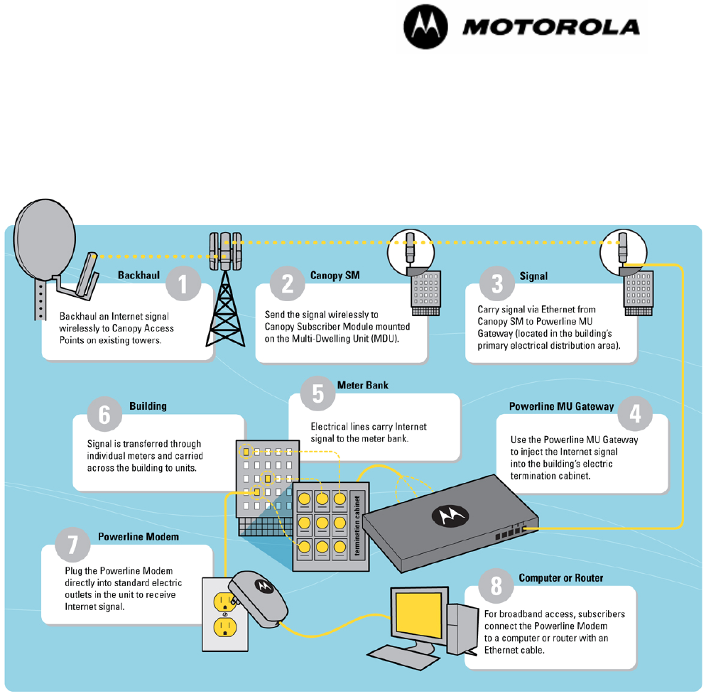
2 OVERVIEW OF POWERLINE MU
Motorola Powerline MU Solution provides a broadband over low-voltage power line
access solution that delivers reliable performance to multiple-dwelling units while
mitigating interference by using low voltage wires. Motorola Powerline MU is designed
for and works with the Canopy™ wireless broadband Internet platform. The standard
Canopy system provides the broadband backbone for the system, creating a wireless
transport system to the hotel, apartment building, or other multiple dwelling unit.
Figure 1 Powerline MU Network Overview
The Canopy Subscriber Module (SM) is the termination unit of the wireless part of the
system and consists of a single transceiver that operates with a 60-degree antenna and
communicates with one or more Access Points (AP). The synchronization and control of
the SM is accomplished via the received AP signal. After the SM is turned on, it scans
the channels and automatically registers with an AP.
The Category 5 Ethernet output cable from the SM plugs directly into the Powerline MU
Gateway unit or via a Powerline MU Hybrid Adapter. Power to the SM is supplied by use
of the SM “pigtail” electric cord. The integrated Subscriber Module (SM)-Powerline
Gateway unit provides signal routing to the Modem devices within the home.
When the Gateway is connected to the low voltage side of the power transformer, digital
data is transmitted over the power line. By using this technique and adding notch filtering

Powerline MU
Page 12 of 112
to Powerline MU carriers, the potential for radio frequency interference is significantly
reduced, especially in the HF radio amateur bands.
Within the home or business, the Powerline Modem fits into any standard AC power
outlet and performs the power line to Ethernet conversion, using the same circuitry as the
Powerline MU Gateway. An Ethernet cable from the Modem to a computer or router
completes the connection.
The Powerline Modem uses the HomePlug® protocol and can coexist without
interference in the same home, but retail HomePlug units cannot take the place of the
Powerline Modem
Careful planning of the Canopy wireless segment of your Powerline MU system is
essential to a successful completion of the network. See “Designing Your Canopy
Network” in the Canopy System User Guide. Follow that guide carefully to achieve a
strong signal at the subscriber modules in the Powerline MU network.
2.1 POWERLINE MU FEATURES
2.1.1 Security
Powerline MU provides the following security solutions:
◦ User ID and Password - The default User ID is admin. The default Password is
Motorola (case sensitive). We recommend these be changed when the system
is deployed to help prevent unauthorized users from accessing the system. This
can be done both locally and via Prizm. A factory reset will change them back to
the defaults.
◦ Authentication (Requires Prizm) - The recommended Authentication method is
via Motorola's Prizm EMS. In addition to monitoring and maintaining
the Powerline equipment, it can also be used for MAC-based authentication for
both the MU and end users. Much like Canopy today, Powerline MU devices can
be managed via Prizm.
◦ Encryption - Data on the Powerline MU network is encrypted using 56-bit Data
Encryption Standard (DES), the HomePlug standard. This prevents any
HomePlug modem from establishing a connection on the network that does not
have the correct Network Encryption Key (NEK). Not only will the modem not be
able to connect to the network, the data packets will not transmit out of the
Ethernet port of the modem to attempt to be decrypted.
◦ Modem isolation - The are two levels of Modem isolation:
A. The first is Virtual Local Area Network (VLAN) tagging. When a Modem is
plugged in, it tries to communicate with a Gateway. If the NEK is correct, the
Gateway and the Modem establish one to one Powerline VLAN communication.
This is internal to the Gateway, so the VLAN ID can be viewed but cannot be
changed without requiring a Gateway reconfiguration. This prevents modems on
the network from having access to data on other modems.
B. The second is in the Modem itself. The modem by default acts as a router.
It requests a DHCP address on the WAN side for management purposes. It also
has a DHCP server for the LAN side so the PC or other device will obtain a
private IP address. In addition, Network Address Translation (NAT) is on, so
each modem (and PC or system under that modem) are on their own private IP
network. The modem addressing can be set to static and NAT turned off if that is
the way the network has been designed.

Powerline MU
Page 13 of 112
These multiple layers of security have been implemented to ensure the security of
the Powerline MU system.
2.1.2 Bandwidth Management
Individual modems may be set for downlink and uplink sustained rates. The network
operator can also select one of eight levels of Quality of Service (QoS) for all traffic to
and from that modem or can use three Type of Service (ToS) bits (three higher order
DSCP bits), which are part of the IP header, to determine QoS of individual packets.
In either case, eight indicated priorities map to 4 classes of service, using the scheme
recommended in 802.1D. See QoS screen, Figure 44 Advanced Packet Priority.
If QoS is set manually using the Web page then it will be added as a part of the VLAN
tag, not part of the IP header.
2.1.3 Network Operations
Powerline MU provides IP address configuration, NAT configuration, and DHCP
configuration for manually or automatically obtaining IP addresses.
By default, NAT is enabled in the Modem.

Powerline MU
Page 14 of 112
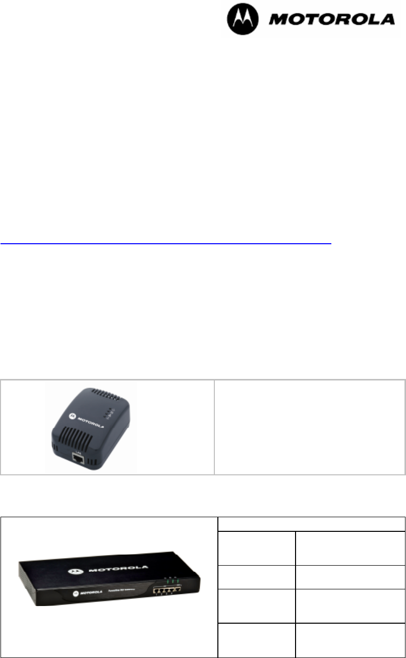
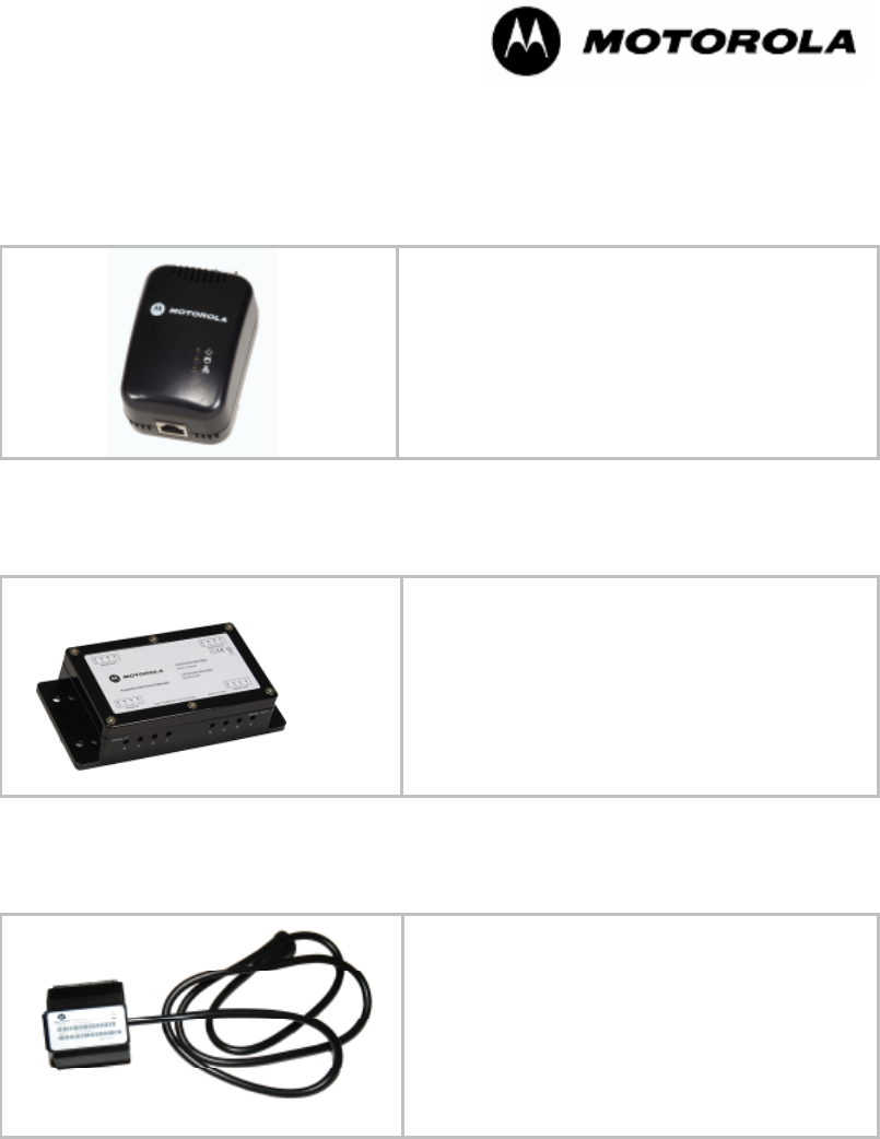
2.2 POWERLINE MU PRODUCTS
The following products are available for Powerline MU networks.
Product Name Part Number
Powerline Modem (US Plug) 0171486N01
Powerline Modem (Type C Plug) 0171486N03
Powerline MU Modem (Type G Plug) 0171486N14
Powerline MU Gateway (US Plug) 0171486N11
Powerline MU Gateway (Type C Plug) 0171486N04
Powerline MU Gateway power cord (Type G Plug) 0171486N19
Powerline MU Gateway 3 capacitive cords (Type G
Plug)
0171486N20
Powerline MU Hybrid Adapter (US Plug) 0171486N02
Powerline MU Hybrid Adapter (Type C Plug) 0171486N08
Powerline MU Panel Extender 0171486N07
Powerline MU Inductive Coupler 500 0171486N21
Powerline MU Inductive Coupler 100 0171486N22
Powerline MU Inductive Coupler 250 0171486N23
Powerline MU Inductive Coupler 750
(available Q4, 2007)
TBD
2.3 ORDERING EQUIPMENT PLUG TYPES
For the Modem and Hybrid Adapters, a plug type must be specified, which will determine
the appropriate part number. See Appendix A for plug types by country to validate your
choice. US Plug and Type C plug Gateways ship with one 6-foot power cord and three 3-
foot coupling cords of the respective plug type. For Gateways using G or I plugs, one
matching power cord and one matching coupling cord kit must be specified by plug type
and ordered in addition to the Type C plug Gateway.
If, however, you plan to install the Gateway using inductive couplers, you need only order
the appropriate power cord.
Before ordering inductive couplers, please see the size chart in section 4.2.3.
Powerline MU
Page 15 of 112
3 Planning the Powerline MU Network
The Powerline MU network consists of three major design considerations:
• Canopy wireless devices
• Powerline MU devices
• Electrical distribution within the building
3.1 CANOPY WIRELESS
Careful planning of the Canopy segment of your network is essential to successful
installation. Measure distances carefully and examine the physical constraints around
the power line installations.
A site survey questionnaire is posted at
http://motorola.canopywireless.com/support/library/?region=1&cat=8
Install Canopy devices, including Backhauls (BH) as needed, Access Points (APs),
Cluster Management Modules (CMMs) as needed, and Subscriber Modules (SMs)
according to installation information provided in the Canopy System User Guide.
3.2 POWERLINE MU
The Powerline MU section of the network consists of the following Motorola Powerline
products:
• Powerline Modem – CPE and Powerline-to-Ethernet adapter
In Package:
1 Powerline Modem
1 Ethernet Cable
Powerline MU Gateway – Head-end and controller for Powerline network
In Package:
1 Powerline MU
Gateway
8 wood screws for
mounting on board or
wall
1 6’ (1.8 meters)
power cord
8 anchors for mounting
on dry wall or plaster
3 3’ (.9 meters)
capacitive
injection cords
6 small screws for
attaching mounting
brackets to Gateway
2 mounting
brackets
Powerline MU
Page 16 of 112
• Powerline MU Hybrid Adapter -- Optional Twisted Pair adapter for utilizing unused
phone lines for Gateway to Canopy Radio connectivity
In Package:
1 Powerline MU Hybrid Adapter
1 CD for changing the name and NEK of the device
• Powerline MU Panel Extender – Accessory to provide coupling between four
separate low-voltage distribution panels
In Package:
1 Powerline MU Panel Extender
Powerline MU Inductive Couplers – Accessory to provide inductive coupling between
the Powerline MU Gateway and electrical termination cabinets.
In Package:
1 Powerline MU Inductive Coupler
Three sizes available August, 2007
See size chart in section 4.2.3.
3.3 CONNECTING THE CANOPY NETWORK TO THE GATEWAY
Internet feed to the Gateway must be considered before the Gateway location is decided.
3.3.1 Ethernet from SM to Gateway
The simplest connection is from the Canopy Subscriber Module (SM) via shielded
Ethernet cable directly to the Gateway. Use straight-through shielded outdoor Ethernet
cables that adhere to Category 5 and 5e (TIA/EIA 568-B). The SM must be plugged into
an AC outlet, as it does not get power over the Ethernet cable.

Powerline MU
Page 17 of 112
This connection may not be possible because of distances limitations (100 meters) or
structural obstacles.
3.3.2 Ethernet from SM to Powerline MU Hybrid Adapter to Powerline MU Hybrid
Adapter to Gateway
Connect the SM to a Powerline MU Hybrid Adapter plugged in to an AC outlet. Use a
straight-through shielded Ethernet cable that adheres to Category 5 and 5e (TIA/EIA 568-
B). Connect a telephone wire to the RJ11 jack on the Powerline MU Hybrid Adapter and
run the telephone wire over existing twisted pair telephone wires to another Hybrid
Adapter that is near the Gateway.
Connect the second Hybrid Adapter to the Gateway using the same kind of Ethernet
cable defined above.
3.4 BUILDING ELECTRICAL CONSIDERATIONS
Most buildings have the same basic layout electrically. They all have a main feed that is
then distributed to the customer premise.
3.4.1 Main Planning
You will need to involve the building manager, a qualified electrician and, perhaps, the
local utility and a local inspector, depending on local regulations and where you
connect the Gateway.
3.4.2 Owners of Electrical Equipment
The meter or the meter bank is usually the separation between the utility (line side) and
the customer (load side). In multiple units buildings (MUs), the building typically owns all
of the equipment all the way to the transformer outside the building, except the meters.
The utility owns the meters and the outside transformer and must be included in plans
that involve gaining access to these devices.
NOTE: Typical Powerline MU installations do not require gaining access to those
devices.
3.4.3 Gateway Location
Choose the location for the MU Gateway(s) and discuss with the building management
who needs to be involved.
The closer you connect to the customer premise, the better, but remember that you will
want to connect to the point that serves the most customers with the least signal loss.
Determine the location of the broadband entrance point, which is the Internet access
device, such as the Motorola Canopy SM.
Determine how to connect the Gateway to the Internet access device:
• Ethernet (from the Motorola Canopy SM)
• Ethernet via fiber
• Powerline MU Hybrid Adapter using telephone wiring
• Other Ethernet connection

Powerline MU
Page 18 of 112
4 Installing Powerline MU
WARNING!
A qualified electrician is required to connect the Powerline MU Gateway to the electrical
panels in the building.
NOTE:
Every effort has been made to use diagrams, symbols, wiring colors and
labels that are accepted universally across all countries. In cases where that is
impossible, North American references are used in this documentation.
The following steps will guide you with your installation:
1. Gather information
You will need to gather information about the electrical system in the building in order to
design your network.
• Locate all distribution points and electrical panels on the electrical
diagram. These areas provide optimal locations for Gateway placement.
• Locate any electricity (power) meters or electricity (power) meter banks.
• Identify which areas of the building are powered by each panel.
• Identify all electrical closets and risers.
• Determine potential connectivity from the panel locations to the main
Internet access point, including telephone cable and conduit access.
2. Find or create an electrical diagram of the building.
Electrical diagrams, which provide details of the building’s electrical layout, are typically
available from the property manager or electrician Perform a site survey to know where
all the power panels are located and determine how you will connect the gateways to the
Internet access point. Be sure you know who has to be involved from an electrical
connectivity standpoint; utility, building owner, etc.
It is a requirement of the standard for electrical installations in buildings that a diagram
chart or schedule is provided, giving details of the installation. Thus such a diagram
should be available, and if any modifications are made when installing the Powerline MU,
they must be recorded.
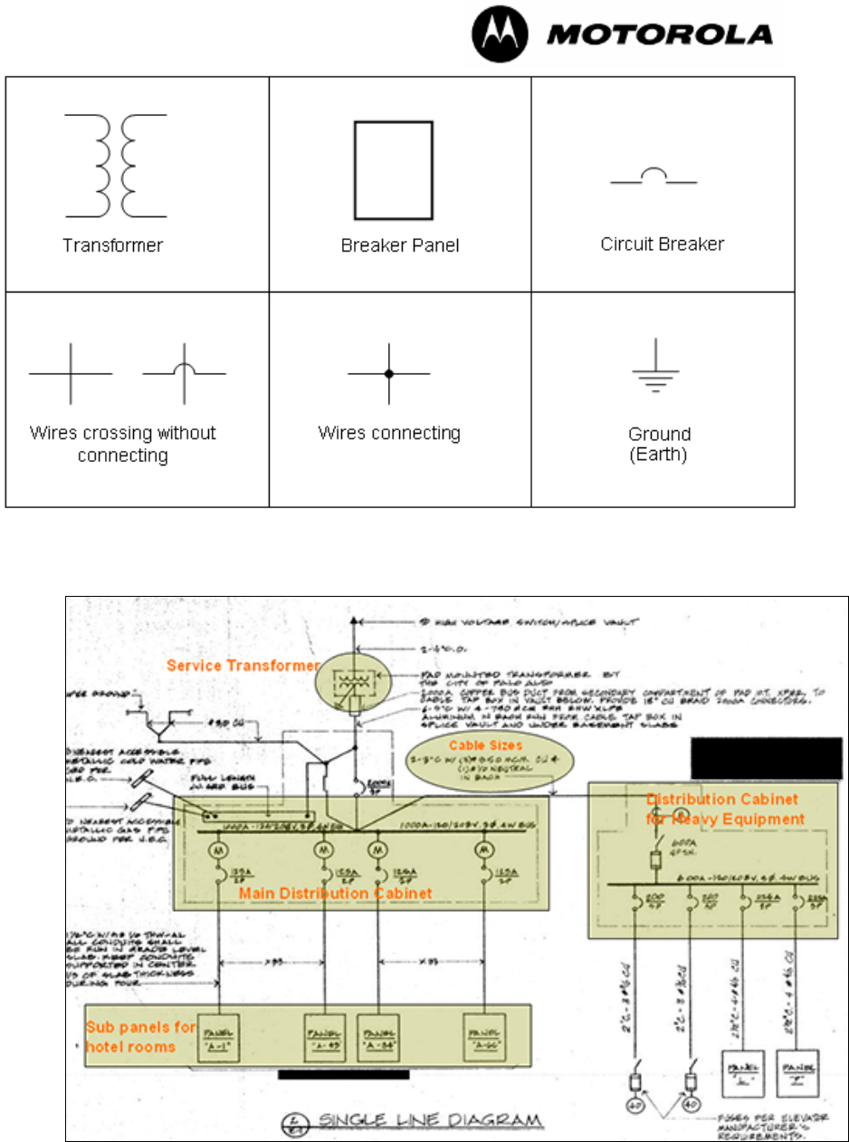
If no electrical diagram is available, however, create one. The following symbols are often
used to denote various electrical devices and connections. Symbols may differ according
to the country of local code where the Powerline MU is being installed. For example,
“Ground” is called “Earth” in some countries. The symbols used in various countries can
be found on the International Electrotechnical Commission (IEC) website (www.iec.ch).
Powerline MU
Page 19 of 112
Figure 2 Electrical Symbols
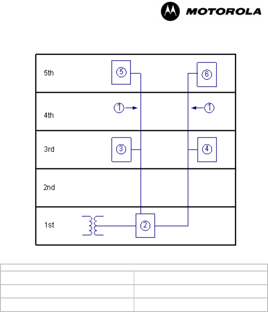
Figure 3 Sample Diagram A
Powerline MU
Page 20 of 112
Figure 4 Sample Diagram B
Legend
(1) 3 Phase, 4 Wire (4) Sub-panel 2 (Sub-distribution Board goes to
rooms 211-220 and to rooms 311-320)
(2) Main Panel (Main Distribution Board) (5) Sub-panel 3 (Sub-distribution Board goes to
rooms 401-410 and to rooms 501-510)
(3) Sub-panel 1 (Sub-distribution Board goes to
rooms 201-210 and to rooms 301-310)
(6) Sub-panel 4 (Sub-distribution Board goes to
rooms 411-420 and to rooms 511-520)
If you create an electrical diagram, include the following information:
• Determine the feeder routes for the electrical distribution.
• Note locations of all distribution points, electrical panels and meter banks.
• Diagram which rooms are connected to which location.
• Include dimensions of the building.
• Note the number of floors.
• Include the dimensions of each floor.
• Note the number of rooms per floor.

Powerline MU
Page 21 of 112
3. Choose the location(s) for the Gateway (s)
Choose the best location(s) for the MU Gateway or Gateways. Select locations that
place the Gateways as close to the users as possible. The gateway also must be close to
the power panel where the network signal will be coupled to the AC distribution.
As with all networking equipment, you should make sure that the area where you are
mounting the equipment has proper ventilation and is not too hot.
4. Determine the location of the broadband access router.
5. Determine how to connect the Gateway(s) to the Internet access device.
– Ethernet
– Hybrid Adapter using telephone wiring
– Wireless
– Powerline with different encryption key
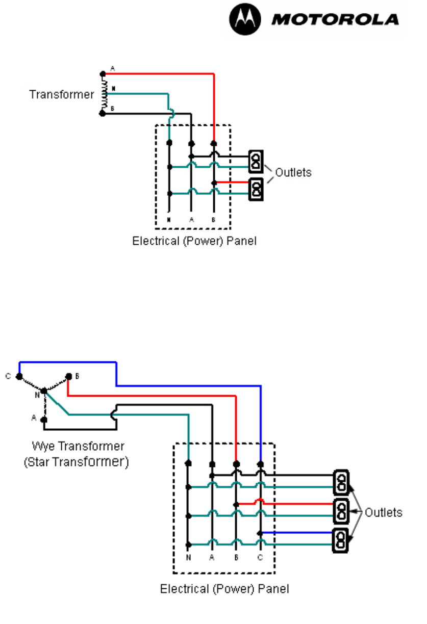
4.1 TWO-PHASE (SINGLE-PHASE) INSTALLATION
Some apartment buildings may be wired for two-phases only, with a single phase to each
apartment. For this type of building, follow instructions for mass-metered installation and
connect only two outlets to the Gateway.
Powerline MU
Page 22 of 112
US colors are shown here. In other countries, the colors may be different.
The electrical (power) panel is sometimes called a distribution panel.
Figure 5 Two-phase installation
4.2 THREE-PHASE INSTALLATION
Most large buildings are served by three-phase electrical service.
European colors are L1=Brown, L2=Black, L3=Grey, N=Blue.
In some countries the electrical (power) panel is called a distribution board.
Figure 6 Three-phase installation
Powerline MU
Page 23 of 112
Commercial building installations will fit in one of the following categories:
• Mass Metered
• Individually Metered, single or three-phase
• Multiple Transformer
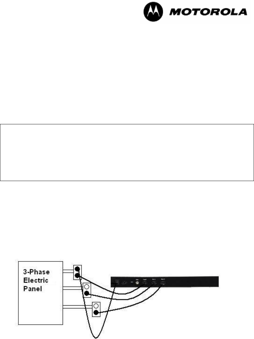
4.2.1 Mass Metered
Mass-metered electrical distribution is typically found in hotels, dormitories, and some
older apartments. These have one meter where the power enters the building, followed
by a large distribution panel that distributes electricity to other smaller sub or breaker
panels, to the rooms or a combination of both.
You must have a qualified electrician install an AC outlet for each low-voltage phase in
the electrical panel for the building. This can be up to three phases.
In the UK and Ireland, former codes required a two-meter distance between outlets on
different phases. While this is no longer considered necessary, some electricians may
prefer that installation. If so, to accommodate the length of the injection cords, install the
outlets in a triangular design so that the Gateway is in the middle and post a caution sign
that the outlets are for use with the Powerline MU Gateway only.
Place the Gateway on a secure table or shelf, or mount it in a rack or on a wall or board.
Plug a capacitive injection cord from each phase outlet to the phase jacks in the
Gateway. (The capacitive injection cords are power cords, but they do not draw
power.)
Plug a power cord from the AC Power jack in the Gateway to an AC outlet (see
illustration).
Figure 7 Mass-metered installation
Powerline MU
Page 24 of 112
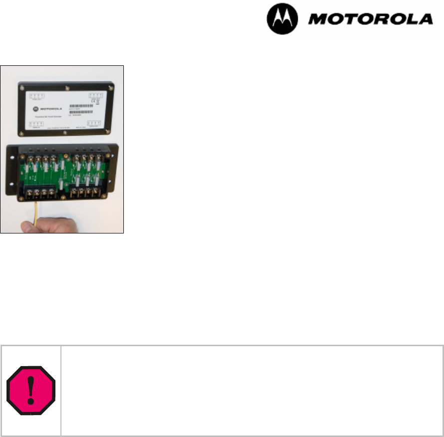
4.2.2 Using a Panel Extender (multiple electrical panels)
Figure 8 Wiring the Panel Extender
To wire the Panel Extender, open the housing and connect 10-
or 14-gauge wires as shown in Figure 8.
Figure 9 Wiring the Panel Extender
Pay careful attention to the “Signal Out” and Signal In” labels. The
“Signal Out” ports are isolated so that the RF signal can pass from
the “Signal In” port through the “Signal Out” ports, but the AC power
cannot, so be sure to connect the newly created outlets to the
“Signal In” port.
Figure 9 Wiring the Panel Extender
WARNING! You must have a qualified electrician install the Panel Extender(s).
The installation should be carried out in accordance with local codes. This
may include mounting the Panel Extender inside an enclosure with conduit
affixed to the enclosure, or using 4-core cable and cable glands.
Once connected, if the product is opened up or in any way mishandled, a risk
of electric shock exists. Installers should insure the Panel Extender is not
easily accessible; for example, housing the device in a locked enclosure.
Create new electrical outlets by extending each phase (typically three) plus neutral from
the first breaker panel. These outlets will be where the Gateway injects the signal onto
the electrical grid. Use unused breakers if available.
Extend four wires (each phase plus neutral) from the newly created outlets to the "Signal
In" port on the Panel Extender. Again, this can be done with the same type of wire used
to create the outlets. Refer to local code for conduit and wire size requirements.
Extend four wires (each phase plus neutral) from the Panel Extender "Signal Out" ports
to up to three additional breaker panels. Four wires will need to be installed and run for
EACH additional breaker panel that is connected. At the subsequent breaker panel,
directly connect the other end of the wire to a breaker on each phase, remembering to
also connect the neutral. Again, use unused breakers if they are available.
The ideal place to connect the Powerline MU Gateway is at the primary breaker panel
that feeds the outlets where signal is needed. Often, there will be additional breaker
panels in the same room or on adjacent floors that service additional outlets where signal
is needed. Signal can be injected into up to four breaker panels simultaneously with the
use of one Panel Extender.
Powerline MU
Page 25 of 112
NOTE: The Panel Extender can only connect breaker panels off of the same
transformer. Be sure that the SAME phases are connected to each other through the
Panel Extender. This can be done with off the shelf electrical testing equipment and by
your qualified electrician.
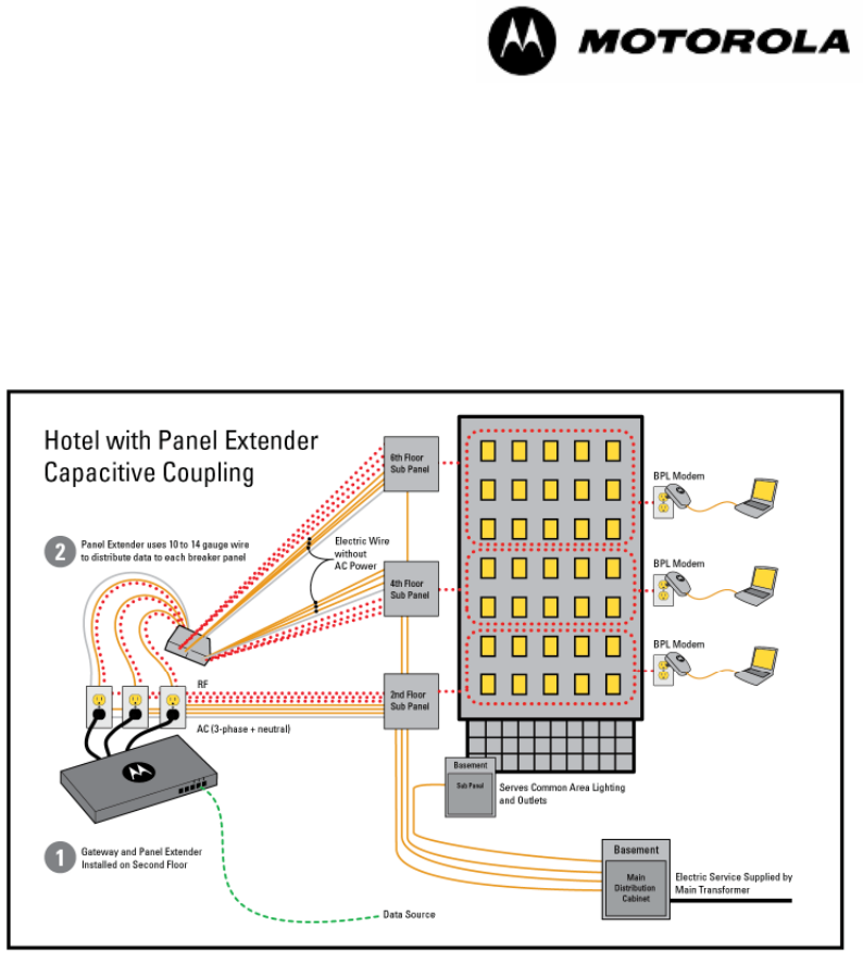
Figure 10 Mass Metered Building with Panel Extender Capacitive Coupling
4.2.3 Individually Metered
Typically found in apartments and condominiums, the individually metered building is
sometimes referred to as “Garden Style.” The electrical distribution will have a large
distribution area, typically located in the basement of the building, followed by one or
more areas that break off to meter banks. Meter banks are groups of meters that
individually monitor power consumption per user premise.
Installation of Powerline MU in individually metered buildings may be accomplished using
capacitive coupling or inductive coupling. The ideal way to install Powerline MU in an
individually metered building is with inductive coupling, which typically requires less time
because there is no need to create additional outlets and provides better signal
penetration because there is less area for signal loss to occur.
Powerline MU
Page 26 of 112
Inductive Coupling
WARNING! You must have a qualified electrician install Inductive Couplers.
Be sure to use proper safety gear, including properly rated electrical gloves
and eyewear. Also be sure to follow the National Electric Code and any local
codes that may apply.
Take care not to drop the open coupler onto bare wire.
Install Powerline MU Inductive Couplers in the termination cabinet. A typical termination
cabinet will consist of cables coming from the transformer outside (line side), a large fuse
breaker, then cables connecting to bus bars that feed the meter bank or banks (load
side). Installing the couplers as close to the load side as possible will generate the best
signal.
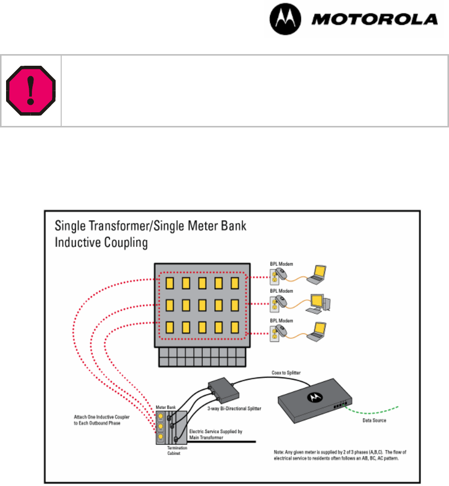
Figure 11 Inductive Coupling Installation Diagram
Inductive couplers are available in sizes to fit snugly on the cables in the cabinet.
Couplers, or “donuts, ”or “CT’s,” are metal rings that wrap around the cables so that the
signal penetrates the outer shield of the cable and onto the lines without actually touching
the bare wire The electrician should determine the size of the couplers.
The ideal location to install inductive couplers is in the termination cabinet. In the
termination cabinet there is a set of electrical cables which may differ in number and size.
This cabinet also houses the bars that feed behind the meter bank. Within the meter
bank, there are meters that measure consumption for each individual dwelling.
Sometimes there will be a larger distribution cabinet that services multiple termination
cabinets and subsequent meter banks. This would also be a location to install the
inductive couplers. In this distribution cabinet, there are multiple cables that feed the
individual termination cabinets. These will also range in both number and size.
Powerline MU
Page 27 of 112
Both the termination and distribution cabinets will be located in one or more electrical
closets in the building. Please consult the building engineer and a qualified electrician to
locate them.
Figure 12 Inductive Coupler Connection, One Transformer
Items Needed
• Couplers: A typical multiple unit will have 4 wires (3 phase + neutral). Some will
have 2 wires (1 phase + neutral) or 3 wires (2 phase + neutral). The sizes will
typically range from 2/0 to 600 MCM.. The most common sizes are 250 MCM
and 500 MCM. A qualified electrician can determine both the number of phases
and size of cabling by inspecting the electrical system. One coupler must be
installed on each phase, but NOT the neutral. In each case, be sure to
choose the proper number and size of couplers.
Powerline MU
Page 28 of 112
Inductive Coupler Sizes
Column A lists the American Wire Gauge sizes, Column B lists Metric Wire Gauge
sizes, and Column C measures the outer diameter of the electric wire installed in the
building. Use that information to choose the recommended Powerline MU Inductive
Coupler from Column D. Column E lists the inner diameter (the ferrite core) of the
Powerline MU Inductive Coupler and Column F provides the part number for that
coupler.
Conductor/Coupler Chart
Column A
Conductor
Size
(American
Wire Gauge)
Column B
Conductor
Size (Metric
Wire Gauge,
mm2)
Column C
Approx
Conductor
Outer Diameter
With Insulation
(mm)
Column D
Recommended
Powerline MU
Inductive
Coupler
Column E
Powerline MU
Coupler Inner
Diameter (mm)
Column F
Motorola
Part
Number
- 400 30.1 750* 31 TBD*
750 MCM - 29.4 750* 31
700 MCM - 28.5 750* 31
600 MCM - 26.7 750* 31
300 26.5 750* 31
500 MCM - 24.9 500 25.4 0171486N21
- 240 24.2 500 25.4
400 MCM - 22 500 25.4
- 185 21.1 500 25.4
350 MCM - 20.6 500 25.4
300 MCM 150 18.5 500 19.4
250 MCM - 17.8 250 19.4 0171486N23
- 120 17.5 250 19.4
4/0 - 16 250 19.4
- 95 15.4 250 19.4
3/0 - 14.7 250 19.4
- 70 13.7 100 14 0171486N22
2/0 - 13.5 100 14
1/0 - 12.2 100 14
- 50 12 100 14
*Powerline MU Inductive Coupler 750 available Q4, 2007.

Powerline MU
Page 29 of 112
• RG6 Coax cable
• Coax Splitters (must include 5-30 MHz in range). Number of splits and splitters
is determined by the number of cables and locations of coupler installation. If
possible, use bi-directional splitters. A possible source for bi-directional splitters
is the Radio Shack® 2-way splitter (Model 15-2587) and the Radio Shack 4-way
splitter (Model 15-2588).
Maximum dB Loss Chart
Number of Splits Maximum dB loss per split
2-way -3.5
3-way -5.7
4-way -7.5
• Conduit Fittings (compression connectors/setscrew couplings)
• Cable Ties as needed
• Rubber Grommets as needed
Procedure
1. Remove the panel of either the termination or distribution cabinets at the desired
location.
2. Determine number of couplers needed.
3. Determine the number of bi-directional splitters needed (if feeding multiple
cabinets).
4. Remove knock-out or create a small hole in the bottom or side of the cabinet.
5. Install conduit fitting in knock-out.
6. Mount the Gateway in the desired location. Be sure to note the distance between
the Gateway location and the location where the couplers will be installed.
7. After determining the length needed, create RG6 coax cable with standard F-
Connectors on each end.
8. Attach the F-Connector from one end of the cable to the back of the Gateway as
shown in Figure 12.
9. Attach the other F-Connector lead (from coax going to Gateway) to the inbound
port on the coax splitter. Attach terminators to any unused ports on the splitter.
10. Feed the coax end of the couplers through the conduit fitting and connect it to the
splitter.
11. Open the coupler by gently lifting on the latch on the housing. The housing is
hinged on the other side so it remains intact. The core itself will be in half, with
one half containing the insulated cable that will induce the RF signal onto the
electrical lines.
12. Connect one coupler to each phase in the cabinet, being sure the plastic case
latches securely together. Be sure the cable stays inside the core when latching.

Powerline MU
Page 30 of 112
Also, be sure not to touch any bare wire or bus bars. (See Figure). Note: To
reduce attenuation, attach the couplers to the LOAD side (to the meters)
cables, not the LINE side (from the transformer) cables, if possible.
13. Be sure couplers do not slide. If needed, use cable ties or rubber grommets to
assure stability.
14. Tighten the conduit fitting to secure the coax cables.
15. Replace the panel of the cabinet.
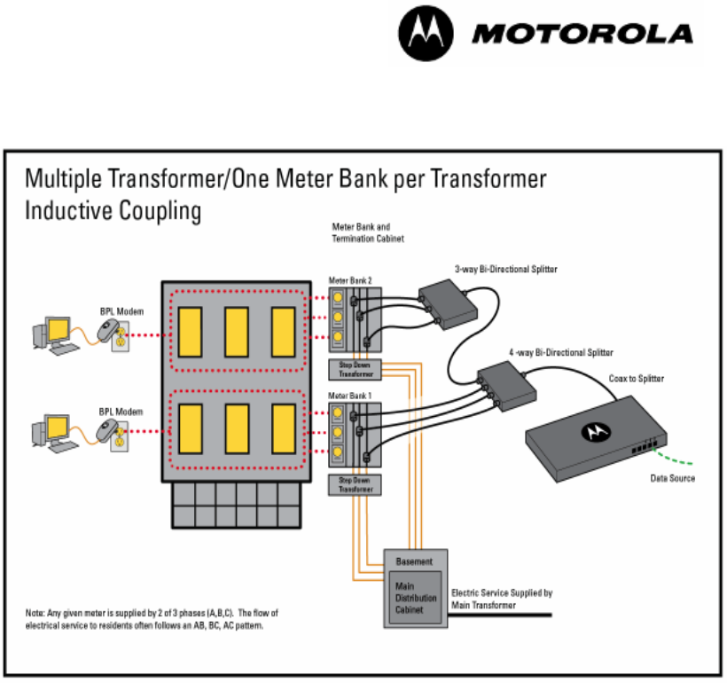
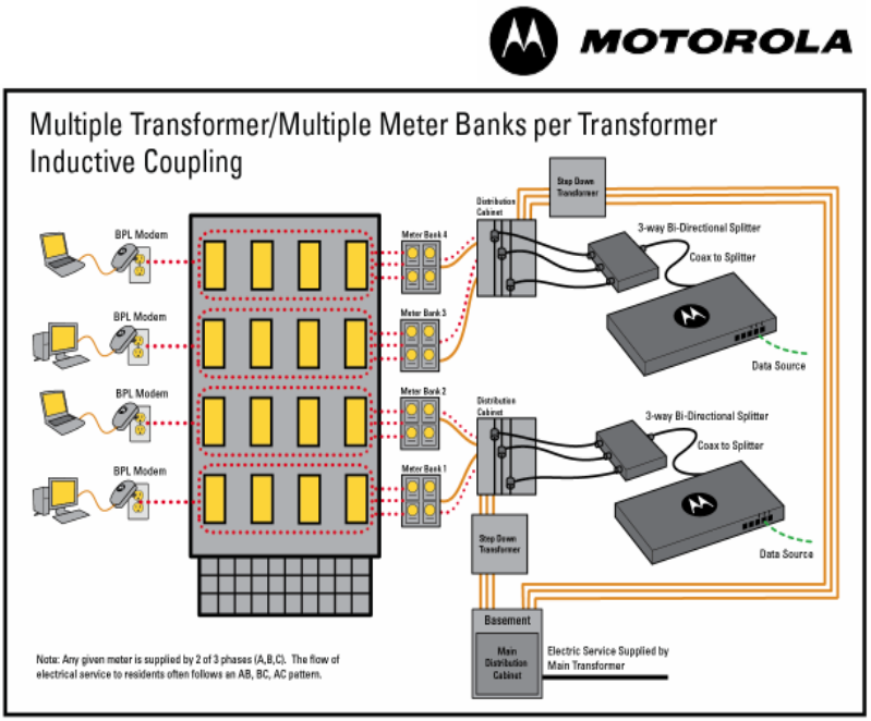
4.2.4 Multiple Transformer
Multiple transformer installations are typically found in high-rises and larger commercial
buildings. If this is a multiple-dwelling unit, it will probably be individually metered, but
with more than one transformer. These buildings often have transformers on multiple
floors and can even have different electrical feeds into the building. These situations
require more planning than the preceding installations and will often require additional
equipment, such as Panel Extenders and Hybrid Adapter units. They will sometimes
even require multiple Gateways. Ideal installation here is similar to the Individually
Metered scenario, but with more planning. The need here is to be sure you can get the
internet connection to each of these Gateways. This can be done with telco cables if
there is conduit.
All of these buildings have the same basic layout electrically. They all have a main feed
that then distributes to the consumer’s premise. The closer you get to the consumer, the
better, but you also want to plan to connect to the point that serves the most customers
with the least signal loss.
Here is one example of an effective coupling solution:
• Install Gateway in 2nd floor electrical closet.
• Couple floors 1-3 together with a Panel Extender.
• Either add a second Gateway on floor 5 for floors 4-6 or extend coupling from initial
Gateway by adding additional splitters, based on signal strength. Try to use no more than
two splits because of signal degradation.
• The signal will not travel back through the 2nd floor transformer and through the
transformers on other floors, so extending the coupling with additional couplers and
splitters will be necessary if one Gateway serves multiple meter banks.
Powerline MU
Page 31 of 112
Figure 13 Inductive Coupler Connection, Multiple Transformers
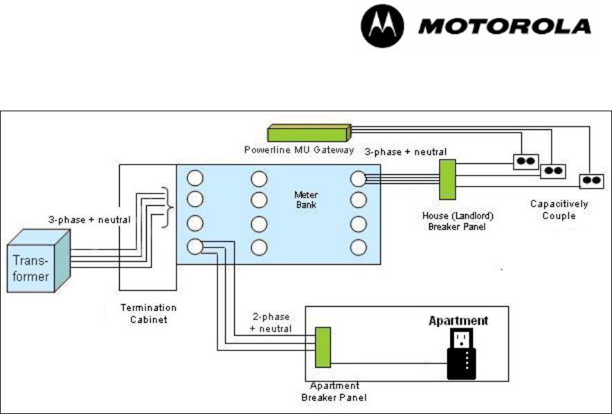
Capacitive Coupling
An ideal place to use capacitive coupling in an individually metered building is directly
after the meter bank. This reduces the attenuation that the meters cause to the signal,
and, in most cases, the local utility will not need to be involved. In some areas, this is not
possible due to the fact that you cannot access the area because of a conduit or other
enclosure.
In most cases, capacitive coupling in an individually metered building will have to be done
AFTER the meter bank. This is best done off of the house (or common or landlord) meter
if it is located in the same room or on the same meter bank as the individual unit meters.
In this case, the RF signal will have to penetrate through the house or common meter,
then through a SECOND meter to get to the individual units. For this reason, inductive
coupling is the better way to install Powerline MU in an individually metered
building.
Powerline MU
Page 32 of 112
Figure 14 Individually-metered installation (capacitive coupling)
Powerline MU
Page 33 of 112
5 Hardware Installation
5.1 UPGRADING FIRMWARE
NOTE: When Upgrading to Firmware Version 2.0 over the Powerline, you must upgrade
the Modems first, then upgrade the Gateway. Failure to do so in this order will result in
loss of communication between the Gateway and Modem.
Upgrades to Powerline MU firmware for the Gateway and the Modem are made available
along with the Canopy upgrade tool. You should become familiar with the tool. Firmware
upgrades and the information about the CNUT upgrade tool are available on the Canopy
website: www.canopywireless.com.
To upgrade the firmware via CNUT, use the following procedure:
Add the Modem to the network, using Edit
Add Canopy Elements to Network Root.
Enter the IP Address of the Modem in the "Add Network Element" window.
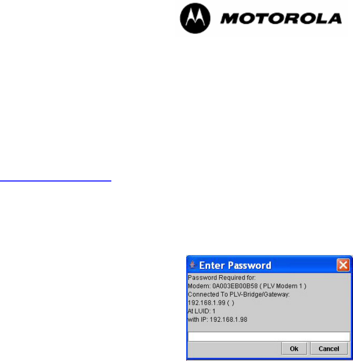
Discover all the Modems in the network, using View
Refresh/Discover Entire
Network. During the discovery process, if the
Enter Password pop-up dialog box appears,
select Cancel.
Add the appropriate Installation Packages to the
Network Updater, using
Update
Manage Packages.
Select the device to be upgraded by selecting the
check boxes next to the device. Upgrade the
device, using Update
Update Selected
Network Elements.
5.2 EQUIPMENT STAGING
Check the Powerline MU devices before installing.
To connect to the Gateway’s web based interface:
1. Connect your PC to the Gateway at one of the Ethernet LAN ports. Be sure the
Gateway is plugged into an AC outlet and turned on.
2. Open your Internet browser and enter the LAN address of the Gateway
connected to your computer.
3. Gateway Default Settings:
• IP 192.168.1.99
• Subnet 255.255.255.0
• DHCP not enabled
Default Login information
– User id admin
– Password Motorola

Powerline MU
Page 34 of 112
To connect to the Modem web based interface:
1. Connect your PC to the Modem Ethernet port.
2. The Modem’s default setting has a DHCP server enabled on the Ethernet
interface. Therefore, if you connect a computer as a DHCP client, you will
receive an IP address from the Modem. However, you may also static an IP
address as follows:
Set your computer’s IP address to
– IP 192.168.1.97
– Subnet 255.255.255.0
Open your Internet browser and enter the LAN address of the Modem connected to
your computer: 192.168.1.98
3. Default Login information
– User id admin
– Password Motorola
The Powerline MU Gateway can be placed on a stable shelf or table, wall mounted, or
installed in a standard 19” equipment rack.
Once installed, connect the power cord to an available receptacle.
5.3 INSTALLATION
Have a qualified electrician install power outlets for the Gateway and other devices in
your design.
Using the 3-foot (.9 meter) capacitive injection cords (included), plug Phase I, Phase II,
and Phase III into the corresponding outlets that were installed by the electrician. The
cords are power cords, but they do not draw electricity.
5.3.1 Mount the Gateway
Connect the Gateway(s) in the proposed location(s) and connect to the network.
The Gateway can be set on a stable shelf or table. It is also designed to mount in a
standard 19” rack. Simply attach the brackets and mount, using rack screws for your
particular rack. The Gateway can also be flush mounted against a wall, either into a wood
wall or on a plywood or solid wood backboard. If mounted in dry wall or plaster, use the
wall anchors supplied with the Gateway.
Plug the Gateway into an available AC outlet. Turn the Power Switch on the back of the
Gateway to ON.
Using a modem and your laptop computer, test connectivity and connection speed in a
sampling of the offices or apartments where connection to the Internet is desired.
Connect to the modem directly and use the Powerline scan feature.
If you have rooms that have a weak signal or no signal, verify that those rooms are
connected to the same area as the Gateway. Repeat this process for each proposed
Gateway location if the design has multiple Gateways. If there are areas with little or no
coverage you will need to modify your Powerline MU design layout.
Powerline MU
Page 35 of 112
Testing can also be achieved using two modems if you have knowledge of the phase
distribution within the building.
5.3.2 Install Modems
Plug Modems in desired locations in each room or unit. Test to be sure connectivity has
been established by connecting a computer and making sure all four lights on the modem
are lit.
If the AC Power light is not lit, you
do not have AC power to your
Modem. Choose another AC outlet.
If the Powerline light is not lit, you
are not connected to the Powerline
network. Try another outlet,
preferably closer to the breaker box
where your electrical power enters
the residence or business. You can use a wireless router at the Motorola Powerline
Modem location to re-establish a connection to the preferred computer location.
If the Ethernet to PC light is not lit, you do not have Ethernet connection to your computer
or router. Check that the Ethernet cable is seated correctly in the Modem jack and in your
PC or router. If that doesn’t help, call your service provider.
If the Registration light is not lit and the other lights are lit, the modem is not registering
on the network.
For more information, consult the Powerline MU Questionnaire and Troubleshooting
Guide on the Powerline MU User Guide section of the Canopy website:
www.motorola.canopywireless.com/support/library/?region=1&cat=8

Powerline MU
Page 36 of 112
6 CONFIGURING THE POWERLINE MU GATEWAY
You must configure the Powerline MU Gateway and Modems for your system. For
easiest setup, configure the components before they are installed.
Gateway Configuration Interface Map
System
System Info
Date and Time
Password
Logs
Reboot
Backup
Site Info
Advanced
BAM Configuration
SNMP Configuration
SNMP Access Control
VLAN Configuration
IP Address
IP Configuration
Powerline
Modem List
NEK Configuration
PSD Settings
Remote NEK
6.1 CONNECT TO THE GATEWAY
To connect to the gateway, use a PC or laptop with a web browser.
Set a static IP address on your Laptop to 192.168.1.97. You may have to temporarily
disable anti-virus software or disable the proxy settings in your computer.
Using a standard CAT-5 Ethernet cable, connect your PC or laptop to one of the
numbered Ethernet ports on the front panel of the gateway. (see Figure 15).
Figure 15 Gateway connected to laptop

Powerline MU
Page 37 of 112
Open your web browser and enter the following Gateway default IP address:
http://192.168.1.99.
Enter your user ID and password.
Factory-installed defaults:
User ID: admin
Password: Motorola
When you first log in the System Info screen will display.
6.1.1 User Interface Navigation tips
The user interface is divided into four main categories:
• System: View and make changes in the system. View the system information
and logs. Set or change the time and date information, change the password,
backup the settings, reboot the system, view site information, and upgrade the
Gateway firmware.
• Advanced: The Advanced screen gives you links for setting up a BAM
(management) server, setting up SNMP Configuration and SNMP Access
Control.
• IP Address: Set the Gateway to obtain an IP address automatically or to use a
specific IP address.
• Powerline: Set the bridge table timeout, view a list of modems, modem MAC
addresses, VID’s, Link Speed, set the Network Encryption Key, and change the
PSD settings.
At the top of each screen is a Home link to go back to the System Information screen and
a Logout link to log out of the Gateway.
Powerline MU
Page 38 of 112
6.2 CONFIGURATION AND MAINTENANCE
6.2.1 System Information
Figure 16 System Information Screen
The System Information screen displays hardware and configuration information about
the Gateway. Select Refresh to view most current information.
6.2.2 Date and Time
Figure 17 Date and Time Screen
Powerline MU
Page 39 of 112
Use the Date and Time screen to set the current date and time on the Gateway (use 24-
hour time format). You can also set the date and time by entering the Network Time
Protocol (NTP) server and selecting Enable.
Select Apply.
6.2.3 System Password Configuration
The factory default user ID for the Gateway is admin and the factory default password is
Motorola. You should change the user ID and password as soon as you log in the first
time.
Use the System Password screen to change the user ID and password for this Gateway.
The user ID and password are case sensitive.
Figure 18 System Password Configuration Screen
Change the user ID and password to enhance security in the Gateway and select Apply.
Determine the auto-logout time (in seconds) and select Apply.
Powerline MU
Page 40 of 112
6.2.4 Logs
Figure 19 Logs Screen
The System Logs screen provides valuable diagnostic tools. The box at the top displays
the current logs.
Select Download to download the log to a file.
Select Clear to clear the log file.
Select Refresh to refresh the screen with current information.
You can set the system log to deliver log files to an email account daily or weekly.
Complete the text boxes on the page and select Apply to set up the system log. Enter
the IP address of the mail server.
Powerline MU
Page 41 of 112
6.2.5 Reboot
Figure 20 Reboot and Reset to Defaults Screen
It may become necessary to reboot the Gateway. Rebooting does not change your
configuration settings.
Select System Reboot to reboot the Gateway.
Select Factory Default to change your Gateway back to the factory default settings for IP
Address and the Password. Note: The PSD values and NEK is not changed during a
Factory Default.
Do not power off the Gateway before you see the affirmation screen.
.
Powerline MU
Page 42 of 112
6.2.6 Backup and Restore Settings
Figure 21 Backup and Restore Settings Screen
When you select Backup Settings you can save the Gateway settings to a local file. To
restore settings, browse for the desired file and select Restore Settings.
6.2.7 Site Info
Figure 22 Site Info Screen
Enter site information and select Apply.
Powerline MU
Page 43 of 112
6.3 ADVANCED
6.3.1 BAM Configuration
Figure 23 BAM Configuration
Enable Authentication Mode and add one or more Authentication Server IPs to use a
bandwidth manager. Select Use Default Key to use the all zeroes key, as shown in the
screen above, or select “Use This Key” and enter a key. The Key must match the key
entered in the bandwidth manager.
64 to 64Kbps 257 to 512 -- 512Kbps 2049 to 4096 -- 4Mbps
65 to 128 -- 128Kbps 513 to 1024 --1Mbps 4097 t0 10240-- 10Mbps
129 to 256 -- 256Kbps 1025 to 2048 -- 2Mbps >10241 -- 42.5Mbps (full speed)
Powerline MU
Page 44 of 112
6.3.2 SNMP Configuration
Figure 24 SNMP Configuration
What is SNMP?
The Simple Network Management Protocol (SNMP) is a TCP/IP application layer protocol
that allows the exchange of management information between network devices. SNMP
enables you to manage network performance and troubleshoot and solve network
problems.
To manage a module, SNMP supports the set command, which instructs the agent to
change the data that manages the module.
To monitor a network element, SNMP supports:
◦ the get command, which instructs the agent to send information about the
module to the manager in the NMS.
◦ traversal operations, which the manager uses to identify supported objects and to
format information about those objects into relational tables.
In a typical Canopy network, the manager issues these commands to the agents of more
than one module.
When a specified event occurs in the module, the agent initiates a trap, for which the
agent sends an unsolicited asynchronous message to the manager.
Select Apply.
NOTE:

Powerline MU
Page 45 of 112
SNMP Get community string can be used to do a "get" operation on the OID's belonging to the
following groups:
whispPlvGatewayInfoGroup, whispPlvGatewayConfigGroup, whispPlvGatewayTrapConfigGroup
and whispPlvGatewayPowerlineGroup of WHISP-PLV-GATEWAY-MIB.
Get community string does not support "set" operation on any of the OID's belonging to WHISP-
PLV-GATEWAY-MIB.
SNMP Set community string can be used to do a "get" and "set" operation on the OID's belonging
to the following groups:
whispPlvGatewayInfoGroup, whispPlvGatewayConfigGroup, whispPlvGatewayTrapConfigGroup
and whispPlvGatewayPowerlineGroup of WHISP-PLV-GATEWAY-MIB.
SNMP Admin Community string can be used to do "get" and "set" operations on all the OID's of
WHISP-PLV-GATEWAY-MIB.
Following table represents the WHISP-PLV-GATEWAY-MIB groups and the community strings
that can be used to access them.
Access Rights using
Groups in WHISP-PLV-GATEWAY-MIB Get
Community
String
Set
Community
String
Admin
Community
String
whispPlvGatewayInfoGroup Get Get Get
whispPlvGatewayConfigGroup Get Get and Set Get and Set
whispPlvGatewayTrapConfigGroup Get Get and Set Get and Set
whispPlvGatewayPowerlineGroup Get Get and Set Get and Set
whispPlvGatewayAdmConfigGroup No Access No Access Get and Set
whispPlvGatewayAdmLanConfigGroup No Access No Access Get and Set
whispPlvGatewayAdmSnmpAccessConfigGroup
No Access No Access Get and Set
whispPlvGatewayAdmWanConfigGroup No Access No Access Get and Set
whispPlvGatewayAdmModemGroup No Access No Access Get and Set
SNMP Get community string can be used to do “get” operation only on all the OID’s of RFC1213-
MIB. SNMP Set and Admin community strings configured in this page can be used to do "get"
and "set" operations on all the OID's of RFC1213-MIB.
Please note that SNMP Manager should load WHISP-GLOBAL-REG-MIB
and WHISP-TC-MIB, to use WHISP-PLV-GATEWAY-MIB.
Powerline MU
Page 46 of 112
6.3.3 SNMP Access Control
Figure 25 SNMP Access Control
Use this screen to control which IP addresses and networks are allowed to SNMP
manage the Gateway. Enter the Access Network Address and Mask and select Apply.
6.3.4 VLAN Configuration
Figure 26 VLAN Configuration
VLAN Configuration Feature, new in Powerline Gateway 2.0
With the new 2.0 Firmware, you will be able to support VLANs in your Powerline MU
network. This functionality enables maximum network performance by allowing for
network isolation, network segmentation and tagging and un-tagging of packets.
A major difference between Motorola Canopy and Powerline MU VLAN functionality is
that unlike Motorola Canopy, Powerline MU can only support either VLAN tagged or
untagged packets, but not both at the same time. Once the mode of operation for the
Powerline MU
Page 47 of 112
Gateway and Modem has been selected, care must be taken to ensure that the entire
network has been properly configured to support VLAN functionality.
There are two main ways that VLAN functionality can be implemented over Powerline.
The first way assumes that the Modems are configured for NAT mode, and the second
method assumes that the Modems are configured in Bridge mode. Figure 4 shows the
test set up for both implementation examples.
Figure 27 An Example Network Configuration for VLAN Implementation.
VLAN Implementation using Modems in NAT Mode
The following steps should be followed when operating Powerline MU in VLAN pass-
through mode. The Powerline MU Gateway must be enabled for VLAN by checking the
“VLAN Enable” box as shown in Figure 28. Figure 28 Example of VLAN Configuration
Screen in the Gateway.Next, enter the Management VID (VLAN ID) for the Powerline
network.
Note: Powerline Management VID must be different from Canopy Management
VID.
After the Gateway has been configured for VLAN pass-through, the LAN and WAN ports
will have different functionality. Where there was no differentiation between the LAN and
WAN ports in standard operating mode, in VLAN mode, the LAN port will only accept
VLAN tagged packets whereas the WAN port will only accept untagged packets.
The WAN port can be used for:
• Connecting a non-VLAN enabled Canopy network to the Gateway, thus allowing for a
hybrid network where the Powerline network is VLAN enabled and the Canopy
network is non-VLAN enabled.
• Connecting to a PC or other non-VLAN IP device to the Powerline network.
Powerline MU
Page 48 of 112
The LAN ports can be used for:
• Extending the network to other Powerline Gateways or other Ethernet based IP
devices since these ports are Bridged.
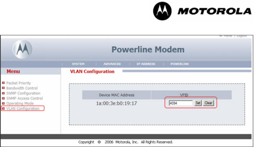
Next, Powerline Modems can now be configured for VLAN pass-through by entering the
VPID (VLAN Pass-Through ID) for the Modem. For example (as shown in Figure 6),
Ethernet packets from devices connected to the Modem will be sent to the LAN port of
the Gateway and tagged with the Modem’s PLC (Powerline) MAC address
(1a:00:3e:b0:19:17 ). Depending on whether the request packets were tagged with the
Management VLAN ID or VPID, the response packets will be tagged with the respective
VLAN ID. For example, if a PC connected to the LAN port of the Gateway sends packets
tagged with VLAN ID = 4094, then the Modem will respond with VLAN ID 4094. If the PC
pings with VLAN ID = 4 (Management VLAN ID), the Modem will respond with VLAN ID
4.
Note: Pass-through VPID can not be the same as the Powerline Management VID.
Powerline MU Modems have a powerful feature that will tag and un-tag packets, however
there is about a 15% decrease in aggregate bandwidth availability because of the
overhead in processing VLAN packets.
DHCP packets sent from the LAN port of the Gateway to the DHCP server will be tagged
with the Management VLAN ID of the Powerline network. To ensure proper network
operation, you will need to either un-tag and tag packets from your DHCP server or install
a VLAN capable network card on the DHCP server.
DMZ can be configured when using the Modem in NAT mode; however, you will not be
able to access the WAN IP address of the Modem until an Ethernet device is connected
to the LAN port of the Modem. As in the prior example, the Modem will match ingress
packet VLAN ID with egress VLAN ID.
Figure 28 Example of VLAN Configuration Screen in the Gateway.
Powerline MU
Page 49 of 112
Figure 29. Example Configuration of a Modem in VLAN Pass-Through Mode.
VLAN Implementation using Modems in Bridge Mode:
Configuration of the Gateway is the same when operating the Modems in Bridge mode.
There are a few differences that you must keep in mind when the modem is in Bridge
Mode.
• It is recommended that DHCP not be enabled for devices connected to the Modem
since DHCP requests are tagged with the VPID.
• Ethernet devices connected to Powerline Modems can be configured for VLAN pass-
through by entering the VPID (VLAN Pass-Through ID) next to the MAC address of
the device. Note: The Modem can only support 128 VPID devices.
• Again, ensure that the Management VID is not used as VPID.
• You may mix Bridge mode and NAT mode Modems on the same Powerline network.
Gateway LUID Range Configuration
Firmware version 2.0 allows for the configuration of the LUID range assignment for
Powerline MU modems (seeFigure 30). This feature allows the ISP full control over their
Powerline deployment by controlling the number of Modems which can register to a
particular Gateway, which can be particularly useful in large-scale MDU deployments. It
is highly recommended that this feature be used to prevent packet collision from Modems
in the same Powerline network by ensuring that multiple Gateways do not assign
overlapping Modem LUIDs.
Note: When deploying multiple Gateways over the same electric grid, it is important to
isolate the Gateways either electrically or ensure that they are using different NEKs.
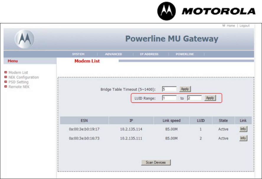
Powerline MU
Page 50 of 112
Figure 30. Modem LUID Range Configuration in the Powerline MU Gateway.
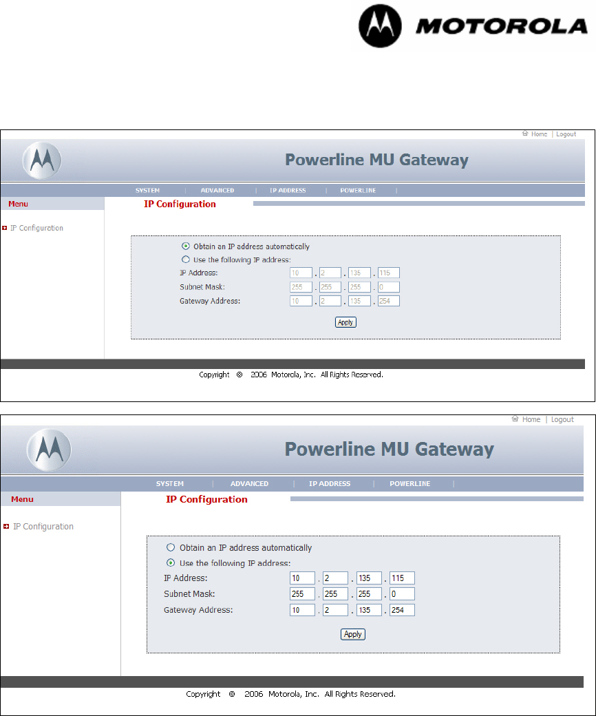
Powerline MU
Page 51 of 112
6.4 IP ADDRESS
6.4.1 IP Configuration
Figure 31 IP Configuration
On this page, you may configure the Gateway to obtain an IP address automatically, or
enter a static P address.
The default IP address is 192.168.1.99.
The subnet mask allows you to break down what appears to be a single large network
into smaller ones, which reduces network overhead.
Select Apply.
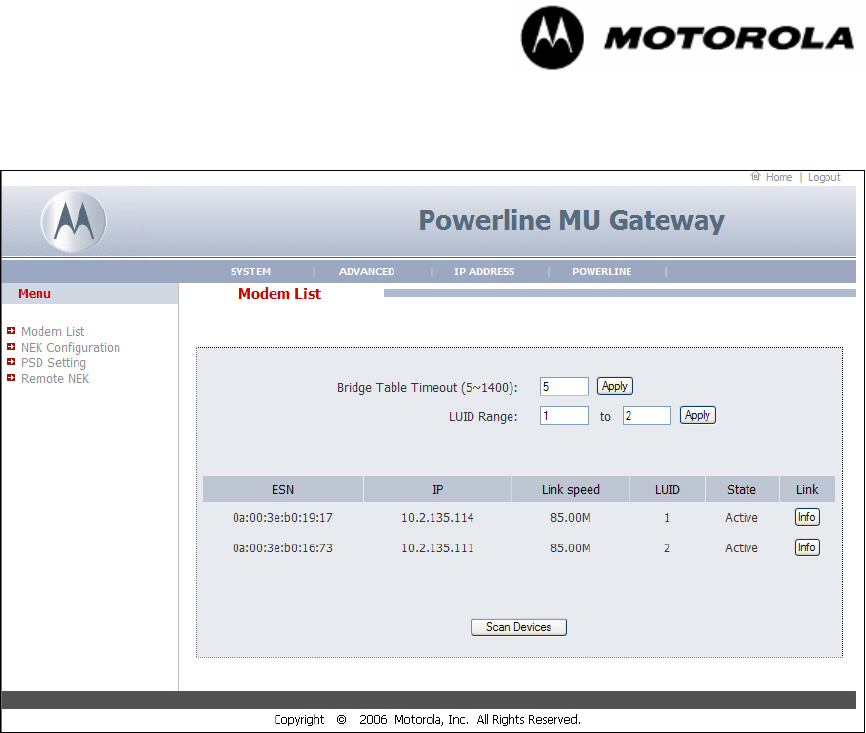
Powerline MU
Page 52 of 112
6.5 POWERLINE
6.5.1 Modem List
Figure 32 Modem List
The Modem List displays a list of all the modems that appear on the Powerline MU
Network. Select Scan Devices to update the list.
Powerline MU
Page 53 of 112
6.5.2 NEK Configuration
Figure 33 NEK Configuration
You may choose a Network Encryption Key (NEK). Remember to change all the
Modems’ NEKs to match the Gateway.
Use the Remote NEK screen to change the NEK on the Modems and any Hybrid Adapter
Modems in the logical network. Hybrid Adapters must match the NEK of each other, but
should not match the Gateway NEK.
The Hybrid Adapter must be physically connected to the Gateway using the Ethernet
cable to change the NEK via this web page.
Select Apply.
Another method for changing the NEK and name of the hybrid adapter is to use the
Administration Utility provided on the CD that was packaged with each Hybrid Adapter.
To install the administration utility, insert the CD in the CD drive of your computer.
Installation should start automatically. If it does not, select RUN and browse for
setup.exe. Select OK.
A manual for using the administration utility is included with the program.
You must have your computer physically connected to the Hybrid Adapter via an Ethernet
cable to make changes using the administration utility.
Both Hybrid Adapters in a system must have the same NEK. Use an NEK that is not the
same as the one for the rest of the network.
Powerline MU
Page 54 of 112
6.5.3 PSD Setting
Figure 34 PSD Setting
The PSD (Power Spectral Density) setting screen provides a place for the end user to
adjust power levels for each Powerline subcarrier. The factory default is 128. Each
subcarrier can be raised or lowered in small steps from 255 down to a value of 0, which
will turn it off.
At a PSD value of 128, the power output of the device is about 22dBm, or -50dBm/Hz.
Lowering the values of the PSD setting will lower the power output of the Gateway and/or
Modem and correspondingly will decrease the distance at which the devices will be able
to communicate. Raising the PSD value increases power output, but if it is raised above
approximately 169, noise will start to degrade the signal. When using the Fixed Value
check box to set all PSD values. The maximum practical value that can be configured is
169. However, setting the PSD value to 169 or higher can cause intermittent behavior
and it is recommended that you use the default value and stay well below 169. If you
wish to change each value, you must do so individually.
The PSD page is designed to allow the system operator to respond quickly to any radio
frequency complaint and adjust Powerline carriers accordingly.
Grayed out values are reserved amateur operator radio frequencies and cannot be
adjusted.
Select Apply.
Powerline MU Carriers Linked to Carrier Frequency.
The following chart links carrier frequency to a carrier channel. If you receive a complaint
from an amateur radio operator that your Powerline MU system is causing interference,
you must work with that person to find out on what frequency the interference exists.
When you have determined the offending frequency, find it on the chart and turn down
the related PSD setting until the interference no longer exists.
The device passes United States FCC testing at PSD settings 128 and lower. Do not
exceed a PSD setting of 60 to be compliant with European regulations. In other regions,
the recommended settings may be different.
Powerline MU
Page 55 of 112
Table 4 Powerline MU Carriers Linked to Carrier Frequency.
Carrier # Center Freq
(MHz) Carrier # Center Freq
(MHz) Carrier # Center Freq
(MHz)
1 4.4921875 29 10.1562500 57 15.6250000
2 4.8828125 30 10.3515625 58 15.8203125
3 5.0781250 31 10.5468750 59 16.0156250
4 5.2734375 32 10.7421875 60 16.2109375
5 5.4687500 33 10.9375000 61 16.4062500
6 5.6640625 34 11.1328125 62 16.6015625
7 5.8593750 35 11.3281250 63 16.7968750
8 6.0546875 36 11.5234375 64 16.9921875
9 6.2500000 37 11.7187500 65 17.1875000
10 6.4453125 38 11.9140625 66 17.3828125
11 6.6406250 39 12.1093750 67 17.5781250
12 6.8359375 40 12.3046875 68 17.7734375
13 7.0312500 41 12.5000000 69 17.9687500
14 7.2265625 42 12.6953125 70 18.1640625
15 7.4218750 43 12.8906250 71 18.3593750
16 7.6171875 44 13.0859375 72 18.5546875
17 7.8125000 45 13.2812500 73 18.7500000
18 8.0078125 46 13.4765625 74 18.9453125
19 8.2031250 47 13.6718750 75 19.1406250
20 8.3984375 48 13.8671875 76 19.3359375
21 8.5937500 49 14.0625000 77 19.5312500
22 8.7890625 50 14.2578125 78 19.7265625
23 8.9843750 51 14.4531250 79 19.9218750
24 9.1796875 52 14.6484375 80 20.1171875
25 9.3750000 53 14.8437500 81 20.3125000
26 9.5703125 54 15.0390625 82 20.5078125
27 9.7656250 55 15.2343750 83 20.7031250
28 9.9609375 56 15.4296875 84 20.8984375
Notched
Powerline MU
Page 56 of 112
6.5.4 Remote NEK
Figure 35 Modem NEK Screen (Powerline Modem)
Figure 36 Modem NEK Screen (Hybrid Adapter)
The NEK on the Modems must be the same as the NEK on the Gateway. Change the
NEK on the Modems BEFORE you change the NEK on the Gateway. Then, change the
NEK on the Gateway
Check “Select All” to make the change on all the Powerline Modems in the system.
Enter the NEK. Select Apply.
Select Powerline MU Adapter if there is a pair of Powerline MU Hybrid Adapters in the
system. The two Hybrid Adapters must have matching NEKs, but they should not agree

Powerline MU
Page 57 of 112
with the NEK on the Gateway. Only the Hybrid Adapter that is connected to the Gateway
can be changed.
To change the NEK of the Hybrid Adapter that connects to the Canopy SM or other
broadband access device, physically carry that Hybrid Adapter to the Gateway and plug it
in to the Ethernet jack. Enter the MAC address of the Hybrid Adapter and the desired
NEK. Be sure both Hybrid Adapters in the system have matching NEKs. Select Apply.
Powerline MU Hybrid Adapter Administration Utility
If desired, you can connect the Hybrid Adapter to a computer and change the NEK for
that device using the Hybrid Adapter Administration Utility. This utility is supplied on the
CD that is in the box with the Powerline MU Hybrid Adapter.
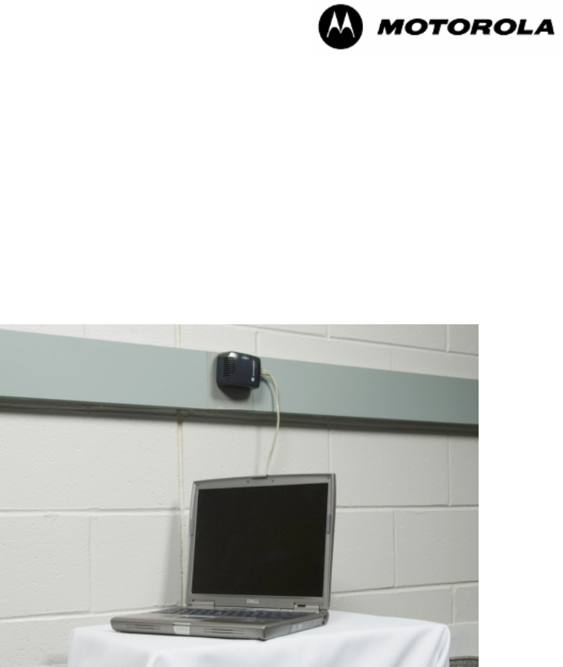
Powerline MU
Page 58 of 112
7 Powerline Modem
Install the Powerline Modem according to the directions included in the package.
Remember that the Gateway NEK and Modems NEK must match.
7.1 CONNECT TO THE MODEM
To connect to the modem, use a PC or laptop with a working Ethernet port and a web
browser.
Set a static IP address on your laptop to 192.168.1.97. You may have to temporarily
disable anti-virus software on your computer.
Using a standard CAT-5 Ethernet cable, connect your PC or laptop to the Ethernet port
on the modem.
Figure 37 Modem Connected to Laptop
Open your web browser and enter the following address:
http://192.168.1.98.
Enter your user ID and password.
Factory-installed defaults:
User ID: admin
Password: Motorola
When you first log in to the Modem, the first page displayed will be the System Info
screen.
7.1.1 User Interface Navigation tips
The user interface is divided into four main categories:

Powerline MU
Page 59 of 112
• System: View and make changes in the system. View the system information
and logs. Set or change the time and date information, change the password,
backup the settings, reboot the system, and upgrade the Modem firmware.
• Advanced: The Advanced screen gives you links for setting Packet Priority,
Bandwidth Control, SNMP Configuration and SNMP Access Control.
• IP Address: Set the Modem to obtain an IP address automatically or to use a
specific IP address. Set WAN and DMZ attributes, if desired.
• Powerline: Scan devices. Set the Network Encryption Key and view or change
PSD settings..
At the top of each screen is a Home link to go back to the System Information screen and
a Logout link to log out of the Modem.
7.2 POWERLINE MODEM SCREEN MAP
Use the following screen map to locate a screen.
System
System Info
Password
Logs
Reset
Backup
Site Info
Advanced
Packet Priority
Bandwidth Control
SNMP Configuration
SNMP Access Control
Operating Mode (Modem Repeater)
VLAN Configuration
IP Address
IP Configuration
WAN
DMZ
Powerline
Scan Devices
NEK Configuration
PSD Settings
7.3 CONFIGURING THE POWERLINE MODEM
Open an Internet browser (for example, Internet Explorer, Mozilla, or Firefox).
In the address field, type 192.168.1.98 (modem default IP address).
In the welcome screen, enter your User ID and password. The factory default User ID is
admin. The password is Motorola. The User ID and password are case sensitive.
Select Login.
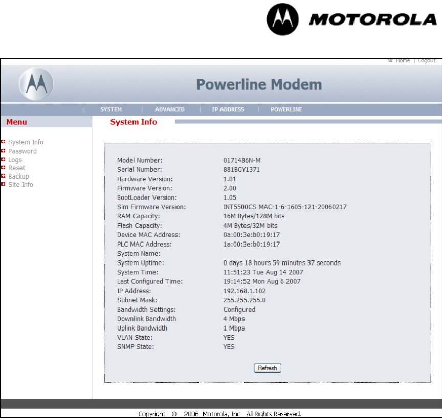
Powerline MU
Page 60 of 112
7.3.1 System Info
Figure 38 System Info Screen
The System Info page gives you a view of the Modem’s status and settings. Select
Refresh to update the information on the screen.
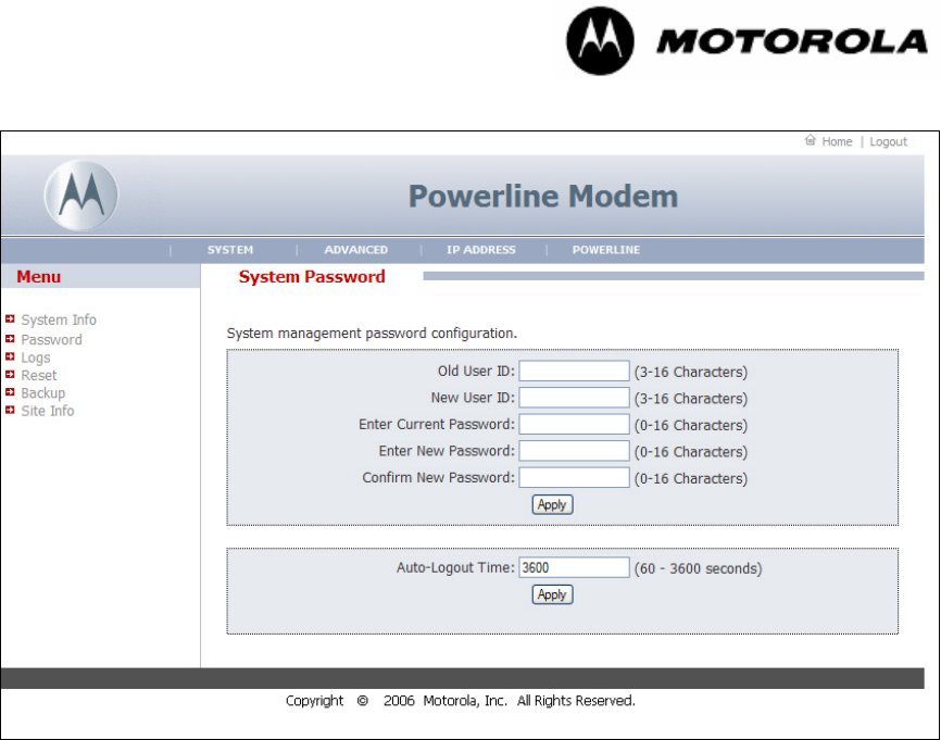
Powerline MU
Page 61 of 112
7.3.2 System Password
Figure 39 System Password Screen
You can change the login information for a modem. The default user ID is admin. The
default password is Motorola. For added security, change the user ID and password
when you configure the modem.
To change the user ID and password:
Enter the old user ID.
Enter the new user ID.
Enter the current password.
Enter the new password.
Enter the new password again.
Select Apply.
To change the time the system will logout automatically, enter a new time, in seconds, in
the box and select Apply.
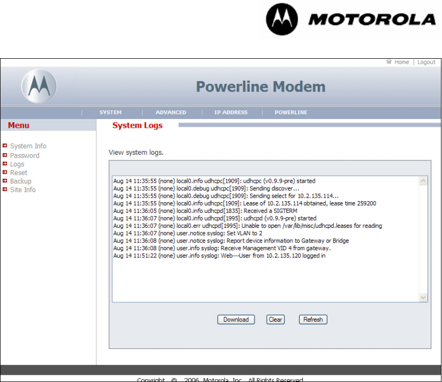
Powerline MU
Page 62 of 112
7.3.3 System Logs
Figure 40 System Logs Screen
The Powerline Modem maintains a system log which displays potential security threats
and system information.
Select Download to save the current information to a file. Select Refresh to update the
information on the screen. Select Clear to clear the logs.
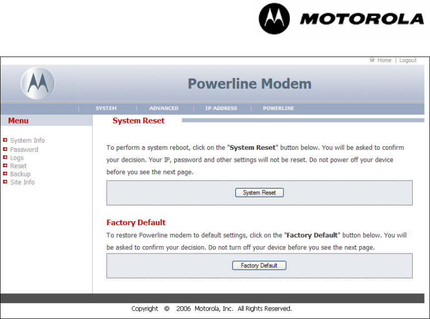
Powerline MU
Page 63 of 112
7.3.4 Reset
Figure 41 Reset Screen
It may become necessary to reset the Modem if it begins working improperly. Resetting
does not change your configuration settings.
Select System Reset to reboot the Modem.
Select Factory Default to change your Modem back to the factory default The NEK &
PSD settings are not changed. Do not power off the Modem before you see the
affirmation screen.
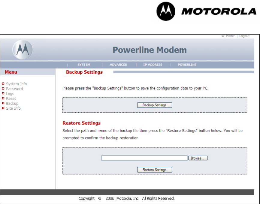
Powerline MU
Page 64 of 112
7.3.5 Backup
Figure 42 Backup Screen
Select Backup Settings to save the current settings to a file. Name the directory and
filename.
Use the Browse button to find the file with the settings you want to restore. Then select
Restore Settings.
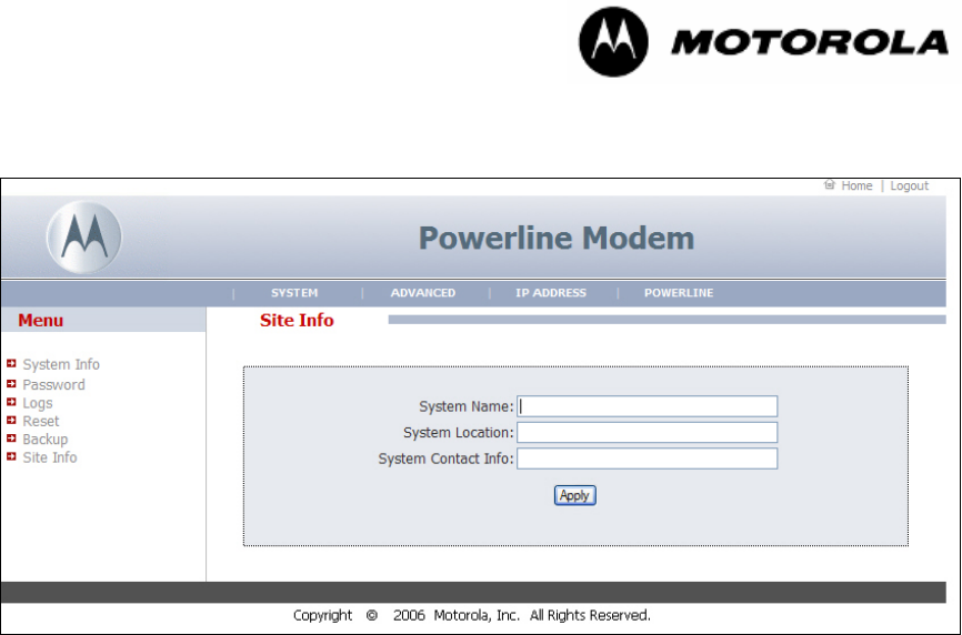
Powerline MU
Page 65 of 112
7.3.6 Site Info
Figure 43 Site Info Screen
Enter the name and location of the modem and the contact information for that modem.
Select Apply.
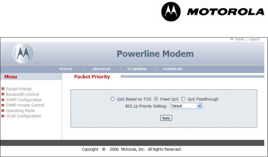
Powerline MU
Page 66 of 112
7.3.7 Advanced Packet Priority
Figure 44 Advanced Packet Priority
Choose the desired Quality of Service (QoS) setting, either based on Type of Service
(ToS), Fixed QoS, or QoS Passthrough. If you choose Fixed QoS, use the drop-down
menu to select the desired priority setting.
Type Of Service (TOS) bits are a set of three-precedence bit flags in the IP header.
When any one of these bit flags is set, routers may handle the datagram differently than
those with no TOS bits set. Each of the three precedence bits has a different purpose
and only one of the TOS bits may be set at any time, so combinations are not allowed.
The bit flags are called Priority bits because they enable the application transmitting the
data to tell the network the type of network service it requires.
The network operator can select one of eight levels of QoS for all traffic to and from that
modem or can use three ToS bits (three higher order DSCP bits), which are part of the
VLAN tag, to determine QoS of individual packets. Select Apply.
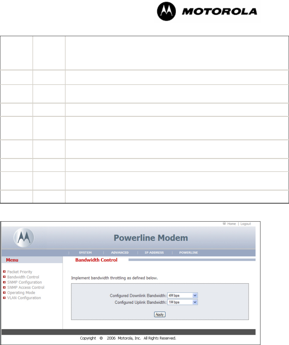
Powerline MU
Page 67 of 112
User
Priorities or
3-bit ToS
setting
Class of
Service
Application class
7 3 Network Control—characterized by a “must get there” requirement to maintain and
support the network infrastructure.
6 3 “Voice”—characterized by less than 10 ms delay, and hence maximum jitter (one
way transmission through the LAN infrastructure of a single campus).
5 2 “Video” or “Audio” —characterized by less than 100 ms delay.
4 2 Controlled Load—important business applications subject to some form of
“admission control,” be that pre-
planning of the network requirement at one extreme
to bandwidth reservation per flow at the time the flow is started at the other.
3 1 Excellent Effort—or “CEO’s best effort,” the best-effort type services that an
information services organization would deliver to its most important customers.
2 0 Best Effort—LAN traffic as we know it today.
1 0 Background—bulk transfers and other activities that are permitted on the network
but that should not impact the use of the network by other users and applications.
0 1 Default
7.3.8 Advanced Bandwidth Control
Figure 45 Advanced Bandwidth Control
Individual modems may be set for downlink and uplink sustained rates. The Advanced
Bandwidth Control allows you to set a specific speed for the specific modem. Use this
control to provide different service to different customers. Select Apply.
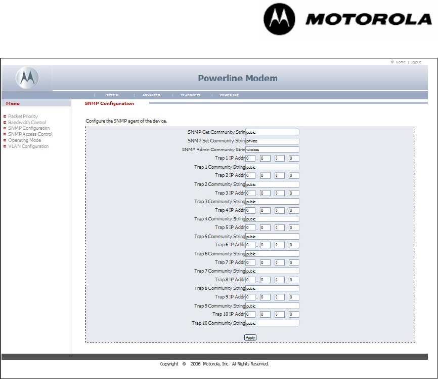
Powerline MU
Page 68 of 112
7.3.9 Advanced SNMP Configuration
Figure 46 Advanced SNMP Configuration
What is SNMP?
The Simple Network Management Protocol (SNMP) is a TCP/IP application layer protocol
that allows the exchange of management information between network devices. SNMP
enables you to manage network performance and troubleshoot and solve network
problems.
To manage a module, SNMP supports the set command, which instructs the agent to
change the data that manages the module.
To monitor a network element, SNMP supports
◦ the get command, which instructs the agent to send information about the
module to the manager in the NMS.
◦ traversal operations, which the manager uses to identify supported objects and to
format information about those objects into relational tables.
In a typical Canopy network, the manager issues these commands to the agents of more
than one module.
When a specified event occurs in the module, the agent initiates a trap, for which the
agent sends an unsolicited asynchronous message to the manager.
Note: The Powerline Modem supports RFC1213-MIB and WHISP-PLV-MODEM-MIB.

Powerline MU
Page 69 of 112
SNMP Get community string can be used to do a "get" operation on the OID's belonging
to the following groups:
whispPlvModemInfoGroup, whispPlvModemConfigGroup,
whispPlvModemTrapConfigGroup of WHISP-PLV-MODEM-MIB.
Get community string does not support "set" operation on any of the OID's belonging to
WHISP-PLV-MODEM-MIB.
SNMP Set community string can be used to do a "get" and "set" operation on the OID's
belonging to the following groups:
whispPlvModemInfoGroup, whispPlvModemConfigGroup,
whispPlvModemTrapConfigGroup of WHISP-PLV-MODEM-MIB.
SNMP Admin Community string can be used to do "get" and "set" operations on all the
OID's of WHISP-PLV-MODEM-MIB.
Following table represents the WHISP-PLV-MODEM-MIB groups and the community
strings that can be used to access them.
Access Rights using
Groups in WHISP-PLV-MODEM-MIB Get
Community
String
Set
Community
String
Admin
Community
String
whispPlvModemInfoGroup Get Get Get
whispPlvModemConfigGroup Get Get and Set Get and Set
whispPlvModemTrapConfigGroup Get Get and Set Get and Set
whispPlvModemAdmConfigGroup No Access No Access Get and Set
whispPlvModemAdmWConfigGroup No Access No Access Get and Set
whispPlvModemAdmSnmpAcessConfigGroup No Access No Access Get and Set
SNMP Get community string can be used to do “get” operation only on all the OID’s of
RFC1213-MIB.
SNMP Set and Admin community strings configured in this page can be used to do "get"
and "set" operations on all the OID's of RFC1213-MIB.
Please note that SNMP Manager should load WHISP-GLOBAL-REG-MIB
and WHISP-TC-MIB, to use WHISP-PLV-MODEM-MIB.
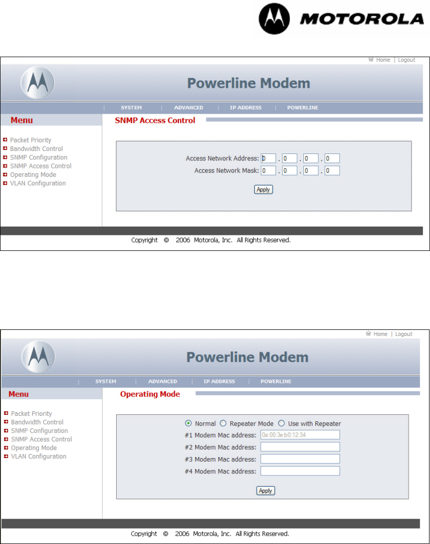
Powerline MU
Page 70 of 112
7.3.10 Advanced SNMP Access Control
Figure 47 SNMP Access Control Screen
Use this screen to control which IP addresses and networks are allowed to SNMP
manage the Modem. Enter the Access Network Address and Mask and select Apply.
7.3.11 Operating Mode (Modem Repeater Function)
Figure 48 IP Operating Mode (Normal)
The “Operating Mode” option allows any Powerline MU Modem to behave as a Repeater
for another Powerline Modem. By turning the first Modem into a Repeater, you can now
connect up to four other Modems through the first Modem (see Figure 49) . The Modem
Repeater is for use in a single residence or office, not for the whole building.
Requirements:
• Modem 2 can not connect to the Gateway.
• In Modem 2, “PowerlineScan Devices” shows the MAC address of Modem 1 with a
good Link Speed (> 20 Mbps).
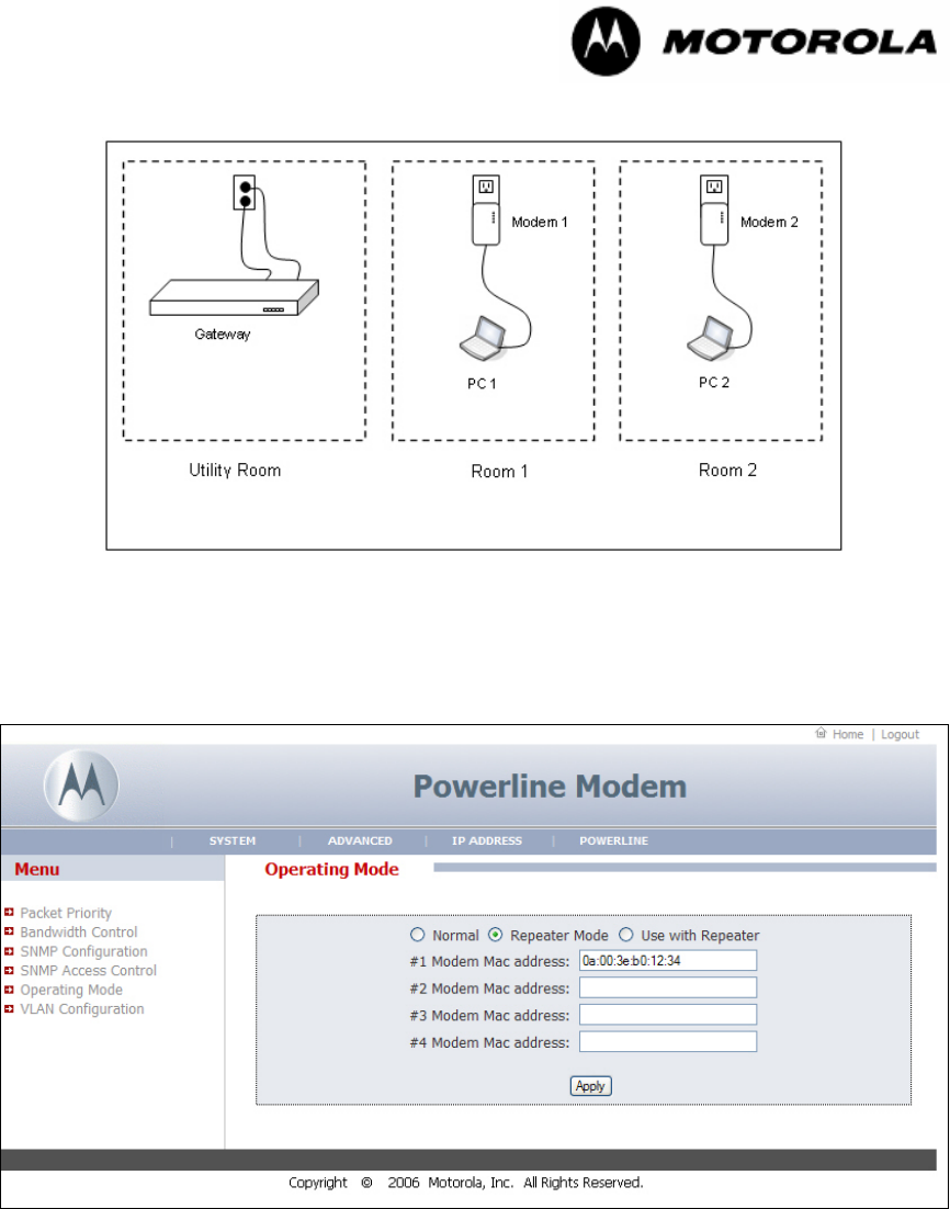
Powerline MU
Page 71 of 112
• Modem 1, Modem 2, and Gateway have the same NEK.
Figure 49 Typical Set Up for the Modem Repeater
Procedure:
To connect Modem 2 to the Gateway, first enable Modem 1 as a Repeater (see Figure
50).
Figure 50 Operating Mode (Repeater)
Procedure:
• Log into Modem 1 and open the “Operating Mode” menu on the left hand panel.
• Select the radio button for “Repeater Mode.”
• Enter the MAC address of Modem 2 into the text input box. Select Apply.
• Log into Modem 2, and open the “Operating Mode” menu on the left hand panel.
• Select the “Use with Repeater” radio button and select Apply.
Note: Modems will reboot when changing the Operating Mode.
Powerline MU
Page 72 of 112
Figure 51 Operating Mode (Use with Re;eater)
General guidelines when using Modems as Repeaters:
• The maximum bandwidth available to Modem 2 is limited to the maximum bandwidth
between the Gateway and Modem 1.
• The maximum bandwidth through Modem 2 will be about ½ of the maximum
bandwidth over Powerline. Indeed you will be able to go about twice the distance
from the Gateway to Modem 1. For example, if the max Layer 2 bandwidth between
the Gateway and Modem 1 is 40 Mbps, then the max usable Layer 2 bandwidth
between Gateway 1 and Modem 2 will be about 20 Mbps.
7.3.12 VLAN Configuration
Figure 52 VLAN Configuration (Modem)
If the Gateway is set up for VLAN pass-through, Modems can now be configured for VLAN pass-
through by entering the VPID (VLAN Pass-Through ID) for the Modem. Ethernet packets from
devices connected to the Modem will be sent to the LAN port of the Gateway and tagged with the
Modem’s PLC (Powerline) MAC address (1a:00:3e:b0:19:17 ). Depending on whether the
Powerline MU
Page 73 of 112
request packets were tagged with the Management VLAN ID or VPID, the response packets will
be tagged with the respective VLAN ID. For example, if a PC connected to the LAN port of the
Gateway sends packets tagged with VLAN ID = 4094, then the Modem will respond with VLAN ID
4094. If the PC pings with VLAN ID = 4 (Management VLAN ID), the Modem will respond with
VLAN ID 4.
7.4 IP CONFIGURATION
Set the Modem to obtain an IP address automatically, or enter a different IP address.
The default IP address is 192.168.1.98.
In the screen shown above, NAT is not enabled.
Powerline MU
Page 74 of 112
7.4.1 IP Configuration with NAT Enabled
Figure 53 IP Address with NAT Enabled Screen
If enabled, NAT (Network Address Translation) allows the Modem to act as an agent
between the Internet and the local network. This means that only a single, unique IP
address is required to represent an entire group of computers.
Powerline MU
Page 75 of 112
7.4.2 WAN
Figure 54 IP Address WAN
Choose whether you want the Modem to obtain an IP address automatically (default) or
to use an IP address you enter.
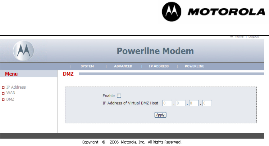
Powerline MU
Page 76 of 112
7.4.3 DMZ
Figure 55 IP Address DMZ
The DMZ (Demilitarized Zone) feature allows you to specify one computer on your
network to be placed outside the firewall. DMZ can be used for connecting servers that
need to be accessible from the outside world. This may be necessary if the firewall is
causing problems with a particular application, such as a game or video conference
application.
DMZ can be configured when using the Modem in NAT mode; however, you will not be
able to access the WAN IP address of the Modem until an Ethernet device is connected
to the LAN port of the Modem. As in the prior example, the Modem will match ingress
packet VLAN ID with egress VLAN ID.
Use this feature on a temporary basis. The computer in the DMZ is not protected by the
firewall.
View and enable or disable the DMZ setting.
IP Address of Virtual DMZ Host: Enter the IP address of the DMZ host.
Select Apply to save the setting.
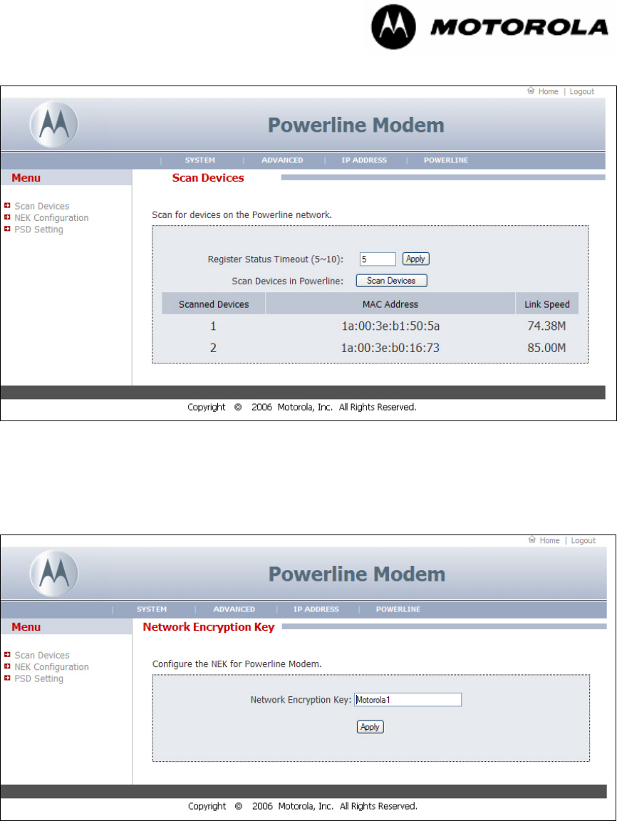
Powerline MU
Page 77 of 112
7.4.4 Scan Devices
Figure 56 Scan Devices Screen
Select Scan Devices. A list of scanned devices on the Powerline Network and the
associated MAC addresses and Link Speed will appear in the box.
7.4.5 Network Encryption Key
Figure 57 Network Encryption Key Screen
To change the Modem Network Encryption Key, enter the new network encryption key
and select Apply. The NEK must be the same as entered in the Gateway.
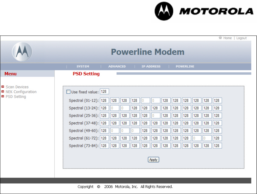
Powerline MU
Page 78 of 112
7.4.6 PSD Setting
Figure 58 PSD Setting Screen
The PSD (Power Spectral Density) setting screen provides a place for the end user to
adjust power levels for each Powerline subcarrier. The factory default is 128. Each
subcarrier can be raised or lowered in small steps from 255 down to a value of 0, which
will turn it off.
At a PSD value of 128, the power output of the device is about 22dBm, or -50dBm/Hz.
Lowering the values of the PSD setting will lower the power output of the gateway and/or
modem and correspondingly will decrease the distance at which the devices will be able
to communicate. Raising the PSD value increases power output, but if it is raised above
approximately 169, noise will start to degrade the signal.
Refer to PSD information for the Gateway, in Section 6.5.3.
The PSD web page is designed to allow the system operator to respond quickly to any
radio frequency complaint and adjust Powerline carriers accordingly.
Grayed out values are reserved HAM radio frequencies and cannot be adjusted.
Select Apply

Powerline MU
Page 79 of 112
8 Legal and Regulatory Notices
8.1 IMPORTANT NOTE ON MODIFICATIONS
Intentional or unintentional changes or modifications to the equipment must not be made unless
under the express consent of the party responsible for compliance. Any such modifications could
void the user’s authority to operate the equipment and will void the manufacturer’s warranty.
8.2 NATIONAL AND REGIONAL REGULATORY NOTICES
8.2.1 U.S. Federal Communication Commission (FCC) Notification
This device complies with part 15 of the US FCC Rules and Regulations. Operation is subject to
the following two conditions: (1) This device may not cause harmful interference, and (2) This
device must accept any interference received, including interference that may cause undesired
operation.
This equipment has been tested and found to comply with the limits for a Class B digital device,
pursuant to Part 15 of the US FCC Rules. These limits are designed to provide reasonable
protection against harmful interference in a residential installation. This equipment generates, uses,
and can radiate radio-frequency energy and, if not installed and used in accordance with these
instructions, may cause harmful interference to radio communications. If this equipment does
cause harmful interference to radio or television reception, which can be determined by turning the
equipment on and off, the user is encouraged to correct the interference by one or more of the
following measures:
◦ Increase the separation between the affected equipment and the unit;
◦ Connect the affected equipment to a power outlet on a different circuit from that which the
receiver is connected to;
◦ Consult the dealer and/or experienced radio/TV technician for help.
8.2.2 Declarations of Conformity
A signed declaration of conformity to the requirements of the Council of the European
Communities follows:
Powerline MU
Page 80 of 112
DECLARATION OF CONFORMITY (Gateway)
Česky [Czech] Motorola tímto prohlašuje, že tento Motorola Powerline MU 0171486Nyy
series, je ve shodě se základními požadavky a dalšími příslušnými
ustanoveními směrnice 1999/5/ES.
Dansk [Danish]
Undertegnede Motorola erklærer herved, at følgende udstyr Motorola
Powerline
MU 0171486Nyy series, overholder de væsentli
ge krav og øvrige relevante krav
i direktiv 1999/5/EF
Hierbij verklaart Motorola dat het toestel Motorola Powerline MU 0171486Nyy
series, in overeenstemming is met de essentiële eisen en de andere
relevante bepalingen van richtlijn 1999/5/EG
Nederlands
[Dutch]
Bij deze verklaart Motorola dat deze Motorola Powerline MU 0171486Nyy
series, voldoet aan de essentiële eisen en aan de overige relevante
bepalingen van Richtlijn 1999/5/EC.
English Hereby, Motorola, declares that this Motorola Powerline MU 0171486Nyy
series, is in compliance with the essential requirements and other relevant
provisions of Directive 1999/5/EC.
Eesti [Estonian]
Käesolevaga kinnitab Motorola seadme Motorola Powerline MU 0171486Nyy
series, vastavust direktiivi 1999/5/EÜ põhinõuetele ja nimetatud direktiivist
tulenevatele teistele asjakohastele sätetele.
Suomi [Finnish]
Motorola vakuuttaa täten että Motorola Powerline MU 0171486Nyy series,
tyyppinen laite on direktiivin 1999/5/EY oleellisten vaatimusten ja sitä
koskevien direktiivin muiden ehtojen mukainen.
Par la présente Motorola déclare que l'appareil Motorola Powerline MU
0171486Nyy series, est conforme aux exigences essentielles et aux autres
dispositions pertinentes de la directive 1999/5/CE
Français
[French]
Par la présente, Motorola déclare que ce Motorola Powerline MU
0171486Nyy series, est conforme aux exigences essentielles et aux autres
dispositions de la directive 1999/5/CE qui lui sont applicables
Hiermit erklärt Motorola, dass sich diese Motorola Powerline MU 0171486Nyy
series, in Übereinstimmung mit den grundlegenden Anforderungen und den
anderen relevanten Vorschriften der Richtlinie 1999/5/EG befindet". (BMWi)
Deutsch
[German]
Hiermit erklärt Motorola die Übereinstimmung des Gerätes Motorola
Powerline MU 0171486Nyy series, mit den grundlegenden Anforderungen
und den anderen relevanten Festlegungen der Richtlinie 1999/5/EG. (Wien)
Ελληνική
[Greek]
ΜΕ ΤΗΝ ΠΑΡΟΥΣΑ Motorola ∆ΗΛΩΝΕΙ ΟΤΙ Motorola Powerline MU
0171486Nyy series, ΣΥΜΜΟΡΦΩΝΕΤΑΙ ΠΡΟΣ ΤΙΣ ΟΥΣΙΩ∆ΕΙΣ
ΑΠΑΙΤΗΣΕΙΣ ΚΑΙ ΤΙΣ ΛΟΙΠΕΣ ΣΧΕΤΙΚΕΣ ∆ΙΑΤΑΞΕΙΣ ΤΗΣ Ο∆ΗΓΙΑΣ
1999/5/ΕΚ

Powerline MU
Page 81 of 112
Magyar
[Hungarian]
Alulírott, Motorola nyilatkozom, hogy a Motorola Powerline MU 0171486Nyy
series, megfelel a vonatkozó alapvetõ követelményeknek és az 1999/5/EC
irányelv egyéb elõírásainak.
Íslenska
[Icelandic]
Hér með lýsir Motorola yfir því að Motorola Powerline MU 0171486Nyy
series, er í samræmi við grunnkröfur og aðrar kröfur, sem gerðar eru í
tilskipun 1999/5/EC.
Italiano [Italian]
Con la presente Motorola dichiara che questo Motorola Powerline MU
0171486Nyy series, è conforme ai requisiti essenziali ed alle altre
disposizioni pertinenti stabilite dalla direttiva 1999/5/CE.
Latviski
[Latvian]
Ar šo Motorola deklarē, ka Motorola Powerline MU 0171486Nyy series, atbilst
Direktīvas 1999/5/EK būtiskajām prasībām un citiem ar to saistītajiem
noteikumiem.
Lietuvių
[Lithuanian]
Šiuo Motorola deklaruoja, kad šis Motorola Powerline MU 0171486Nyy
series, atitinka esminius reikalavimus ir kitas 1999/5/EB Direktyvos nuostatas.
Malti [Maltese] Hawnhekk, Motorola, jiddikjara li dan Motorola Powerline MU 0171486Nyy
series, jikkonforma mal-ħtiġijiet essenzjali u ma provvedimenti oħrajn relevanti
li hemm fid-Dirrettiva 1999/5/EC
Norsk
[Norwegian]
Motorola erklærer herved at utstyret Motorola Powerline MU 0171486Nyy
series, er i samsvar med de grunnleggende krav og øvrige relevante krav i
direktiv 1999/5/EF.
Slovensky
[Slovak]
Motorola týmto vyhlasuje, že Motorola Powerline MU 0171486Nyy series,
spĺňa základné požiadavky a všetky príslušné ustanovenia Smernice
1999/5/ES.
Slovensko
[Slovenian]
Motorola izjavlja, da je ta Motorola Powerline MU 0171486Nyy series, v
skladu z bistvenimi zahtevami in ostalimi relevantnimi določili direktive
1999/5/ES.
Svenska
Swedish
Härmed intygar Motorola att denna Motorola Powerline MU 0171486Nyy
series, står I överensstämmelse med de väsentliga egenskapskrav och övriga
relevanta bestämmelser som framgår av direktiv 1999/5/EG.
Español
[Spanish]
Por medio de la presente Motorola declara que el Motorola Powerline MU
0171486Nyy series, cumple con los requisitos esenciales y cualesquiera
otras disposiciones aplicables o exigibles de la Directiva 1999/5/CE
Polski [Polish] Niniejszym, firma Motorola oświadcza, że produkt serii Motorola Powerline
MU 0171486Nyy series, spełnia zasadnicze wymagania i inne istotne
postanowienia Dyrektywy 1999/5/EC.
Português
[Portuguese]
Motorola declara que este Motorola Powerline MU 0171486Nyy series, está
conforme com os requisitos essenciais e outras disposições da Directiva
1999/5/CE.
Powerline MU
Page 82 of 112
DECLARATION OF CONFORMITY
Motorola declares under it sole responsibility that the products, to which this
declaration relates, conform to the applicable essential requirements of the following
Directive(s) of the Council of the European Communities:
• 1999/5/EC of the European Parliament and of the Council of 9 March 1999 on the
radio equipment and telecommunications terminal equipment and the mutual
recognition of their conformity (R&TTE Directive).
• 89/336/EEC of 3 May 1989 on the approximation of the laws of the Member States
relating to electromagnetic compatibility (EMC Directive).
• 72/23/EEC of 19 February 1973 on the harmonization of the laws of the Member
States relating to electrical equipment designed for use within certain voltage limits
(LV Directive).
Product: Model: Motorola Powerline MU Gateway 0171486Nyy
Where “yy”=”04”
Model
Number
Description
0171486N04
Powerline MU Gateway Type C Plug – 2
round pin European
Manufacturer: Motorola Inc.
Description: Power Line Communication Device (PLC Gateway)
Conformity: Harmonized standards used to demonstrate conformity:
The products have been shown to meet the following requirements:
a) Safety – certified to EN 60950-1:2001+A11:2004 First Edition
b) EMC – certified to meet EN55022:1998+A1:2000+A2:2003 (class B),
EN55024:1998+A1:2001+A2:2003, CISPR/I/xyz/DPAS CISPR 22 A2 f9 Ed 4.0
with T-ISN, EN 61000-3-2:2000+A2:2005, EN 61000-3-3+A1:2001+A2:2005
Year of first application of CE mark: 2007
Notified Body number: 0682
Notified Body address: CETECOM ICT Services GmbH, Untertürkheimer Straße 6-
10, D-66117 Saarbrücken, Germany
Signature:
______________________ _______________________
Name: Philip Bolt Aaron Ratner
Title:_______________________ Title: Canopy Quality Manager
Date: June 1, 2007

Powerline MU
Page 83 of 112
DECLARATION OF CONFORMITY (Modem)
Česky [Czech] Motorola tímto prohlašuje, že tento Motorola Powerline MU 0171486Nxx
series, je ve shodě se základními požadavky a dalšími příslušnými
ustanoveními směrnice 1999/5/ES.
Dansk [Danish]
Undertegnede Motorola erklærer herved, at følgende udstyr Motorola
Powerline
MU 0171486Nxx series,
overholder de væsentlige krav og øvrige relevante krav
i direktiv 1999/5/EF
Hierbij verklaart Motorola dat het toestel Motorola Powerline MU 0171486Nxx
series, in overeenstemming is met de essentiële eisen en de andere
relevante bepalingen van richtlijn 1999/5/EG
Nederlands
[Dutch]
Bij deze verklaart Motorola dat deze Motorola Powerline MU 0171486Nxx
series, voldoet aan de essentiële eisen en aan de overige relevante
bepalingen van Richtlijn 1999/5/EC.
English Hereby, Motorola, declares that this Motorola Powerline MU 0171486Nxx
series, is in compliance with the essential requirements and other relevant
provisions of Directive 1999/5/EC.
Eesti [Estonian]
Käesolevaga kinnitab Motorola seadme Motorola Powerline MU 0171486Nxx
series, vastavust direktiivi 1999/5/EÜ põhinõuetele ja nimetatud direktiivist
tulenevatele teistele asjakohastele sätetele.
Suomi [Finnish]
Motorola vakuuttaa täten että Motorola Powerline MU 0171486Nxx series,
tyyppinen laite on direktiivin 1999/5/EY oleellisten vaatimusten ja sitä
koskevien direktiivin muiden ehtojen mukainen.
Par la présente Motorola déclare que l'appareil Motorola Powerline MU
0171486Nxx series, est conforme aux exigences essentielles et aux autres
dispositions pertinentes de la directive 1999/5/CE
Français
[French]
Par la présente, Motorola déclare que ce Motorola Powerline MU
0171486Nxx series, est conforme aux exigences essentielles et aux autres
dispositions de la directive 1999/5/CE qui lui sont applicables
Hiermit erklärt Motorola, dass sich diese Motorola Powerline MU 0171486Nxx
series, in Übereinstimmung mit den grundlegenden Anforderungen und den
anderen relevanten Vorschriften der Richtlinie 1999/5/EG befindet". (BMWi)
Deutsch
[German]
Hiermit erklärt Motorola die Übereinstimmung des Gerätes Motorola
Powerline MU 0171486Nxx series, mit den grundlegenden Anforderungen
und den anderen relevanten Festlegungen der Richtlinie 1999/5/EG. (Wien)
Ελληνική
[Greek]
ΜΕ ΤΗΝ ΠΑΡΟΥΣΑ Motorola ∆ΗΛΩΝΕΙ ΟΤΙ Motorola Powerline MU
0171486Nxx series, ΣΥΜΜΟΡΦΩΝΕΤΑΙ ΠΡΟΣ ΤΙΣ ΟΥΣΙΩ∆ΕΙΣ
ΑΠΑΙΤΗΣΕΙΣ ΚΑΙ ΤΙΣ ΛΟΙΠΕΣ ΣΧΕΤΙΚΕΣ ∆ΙΑΤΑΞΕΙΣ ΤΗΣ Ο∆ΗΓΙΑΣ
1999/5/ΕΚ

Powerline MU
Page 84 of 112
Magyar
[Hungarian]
Alulírott, Motorola nyilatkozom, hogy a Motorola Powerline MU 0171486Nxx
series, megfelel a vonatkozó alapvetõ követelményeknek és az 1999/5/EC
irányelv egyéb elõírásainak.
Íslenska
[Icelandic]
Hér með lýsir Motorola yfir því að Motorola Powerline MU 0171486Nxx
series, er í samræmi við grunnkröfur og aðrar kröfur, sem gerðar eru í
tilskipun 1999/5/EC.
Italiano [Italian]
Con la presente Motorola dichiara che questo Motorola Powerline MU
0171486Nxx series, è conforme ai requisiti essenziali ed alle altre
disposizioni pertinenti stabilite dalla direttiva 1999/5/CE.
Latviski
[Latvian]
Ar šo Motorola deklarē, ka Motorola Powerline MU 0171486Nxx series, atbilst
Direktīvas 1999/5/EK būtiskajām prasībām un citiem ar to saistītajiem
noteikumiem.
Lietuvių
[Lithuanian]
Šiuo Motorola deklaruoja, kad šis Motorola Powerline MU 0171486Nxx
series, atitinka esminius reikalavimus ir kitas 1999/5/EB Direktyvos nuostatas.
Malti [Maltese] Hawnhekk, Motorola, jiddikjara li dan Motorola Powerline MU 0171486Nxx
series, jikkonforma mal-ħtiġijiet essenzjali u ma provvedimenti oħrajn relevanti
li hemm fid-Dirrettiva 1999/5/EC
Norsk
[Norwegian]
Motorola erklærer herved at utstyret Motorola Powerline MU 0171486Nxx
series, er i samsvar med de grunnleggende krav og øvrige relevante krav i
direktiv 1999/5/EF.
Slovensky
[Slovak]
Motorola týmto vyhlasuje, že Motorola Powerline MU 0171486Nxx series,
spĺňa základné požiadavky a všetky príslušné ustanovenia Smernice
1999/5/ES.
Slovensko
[Slovenian]
Motorola izjavlja, da je ta Motorola Powerline MU 0171486Nxx series, v
skladu z bistvenimi zahtevami in ostalimi relevantnimi določili direktive
1999/5/ES.
Svenska
Swedish
Härmed intygar Motorola att denna Motorola Powerline MU 0171486Nxx
series, står I överensstämmelse med de väsentliga egenskapskrav och övriga
relevanta bestämmelser som framgår av direktiv 1999/5/EG.
Español
[Spanish]
Por medio de la presente Motorola declara que el Motorola Powerline MU
0171486Nxx series, cumple con los requisitos esenciales y cualesquiera
otras disposiciones aplicables o exigibles de la Directiva 1999/5/CE
Polski [Polish] Niniejszym, firma Motorola oświadcza, że produkt serii Motorola Powerline
MU 0171486Nxx series, spełnia zasadnicze wymagania i inne istotne
postanowienia Dyrektywy 1999/5/EC.
Português
[Portuguese]
Motorola declara que este Motorola Powerline MU 0171486Nxx series, está
conforme com os requisitos essenciais e outras disposições da Directiva
1999/5/CE.
Powerline MU
Page 85 of 112
DECLARATION OF CONFORMITY
Motorola declares under it sole responsibility that the products, to which this
declaration relates, conform to the applicable essential requirements of the following
Directive(s) of the Council of the European Communities:
• 1999/5/EC of the European Parliament and of the Council of 9 March 1999 on the
radio equipment and telecommunications terminal equipment and the mutual
recognition of their conformity (R&TTE Directive).
• 89/336/EEC of 3 May 1989 on the approximation of the laws of the Member States
relating to electromagnetic compatibility (EMC Directive).
• 72/23/EEC of 19 February 1973 on the harmonization of the laws of the Member
States relating to electrical equipment designed for use within certain voltage limits
(LV Directive).
Product: Model: Motorola Powerline MU Modem 0171486Nxx
Where “xx”=”03”, “14”
Model
Number
Description
0171486N03
Powerline MU Modem Type C Plug – 2
round pin European
0171486N14
Powerline MU Modem Type G Plug –
UK, Ireland
Manufacturer: Motorola Inc.
Description: Power Line Communication Device (PLC Modem)
Conformity: Harmonized standards used to demonstrate conformity:
The products have been shown to meet the following requirements:
c) Safety – certified to EN 60950-1:2001+A11:2004 First Edition
d) EMC – certified to meet EN55022:1998+A1:2000+A2:2003 (class B),
EN55024:1998+A1:2001+A2:2003, CISPR/I/xyz/DPAS CISPR 22 A2 f9 Ed 4.0
with T-ISN, EN 61000-3-2:2000+A2:2005, EN 61000-3-3+A1:2001+A2:2005
Year of first application of CE mark: 2007
Notified Body number: 0682
Notified Body address: CETECOM ICT Services GmbH, Untertürkheimer Straße 6-
10, D-66117 Saarbrücken, Germany
Signature:
______________________ _______________________
Name: Philip Bolt Aaron Ratner
Title:_______________________ Title: Canopy Quality Manager
Date: June 1, 2007

Powerline MU
Page 86 of 112
DECLARATION OF CONFORMITY (Hybrid Adapter)
Česky [Czech] Motorola tímto prohlašuje, že tento Motorola Powerline MU 0171486N08, je
ve shodě se základními požadavky a dalšími příslušnými ustanoveními
směrnice 1999/5/ES.
Dansk [Danish]
Undertegnede Motorola erklærer herved, at følgende udstyr Motorola
Powerline
MU 0171486N08, overholder de væsentlige krav og øvrige relevante krav i
direktiv 1999/5/EF
Hierbij verklaart Motorola dat het toestel Motorola Powerline MU
0171486N08, in overeenstemming is met de essentiële eisen en de andere
relevante bepalingen van richtlijn 1999/5/EG
Nederlands
[Dutch]
Bij deze verklaart Motorola dat deze Motorola Powerline MU 0171486N08,
voldoet aan de essentiële eisen en aan de overige relevante bepalingen van
Richtlijn 1999/5/EC.
English Hereby, Motorola, declares that this Motorola Powerline MU 0171486N08, is
in compliance with the essential requirements and other relevant provisions of
Directive 1999/5/EC.
Eesti [Estonian]
Käesolevaga kinnitab Motorola seadme Motorola Powerline MU 0171486N08,
vastavust direktiivi 1999/5/EÜ põhinõuetele ja nimetatud direktiivist
tulenevatele teistele asjakohastele sätetele.
Suomi [Finnish]
Motorola vakuuttaa täten että Motorola Powerline MU 0171486N08, tyyppinen
laite on direktiivin 1999/5/EY oleellisten vaatimusten ja sitä koskevien
direktiivin muiden ehtojen mukainen.
Par la présente Motorola déclare que l'appareil Motorola Powerline MU
0171486N08, est conforme aux exigences essentielles et aux autres
dispositions pertinentes de la directive 1999/5/CE
Français
[French]
Par la présente, Motorola déclare que ce Motorola Powerline MU
0171486N08, est conforme aux exigences essentielles et aux autres
dispositions de la directive 1999/5/CE qui lui sont applicables
Hiermit erklärt Motorola, dass sich diese Motorola Powerline MU
0171486N08, in Übereinstimmung mit den grundlegenden Anforderungen und
den anderen relevanten Vorschriften der Richtlinie 1999/5/EG befindet".
(BMWi)
Deutsch
[German]
Hiermit erklärt Motorola die Übereinstimmung des Gerätes Motorola
Powerline MU 0171486N08, mit den grundlegenden Anforderungen und den
anderen relevanten Festlegungen der Richtlinie 1999/5/EG. (Wien)
Ελληνική
[Greek]
ΜΕ ΤΗΝ ΠΑΡΟΥΣΑ Motorola ∆ΗΛΩΝΕΙ ΟΤΙ Motorola Powerline MU
0171486N08, ΣΥΜΜΟΡΦΩΝΕΤΑΙ ΠΡΟΣ ΤΙΣ ΟΥΣΙΩ∆ΕΙΣ ΑΠΑΙΤΗΣΕΙΣ ΚΑΙ
ΤΙΣ ΛΟΙΠΕΣ ΣΧΕΤΙΚΕΣ ∆ΙΑΤΑΞΕΙΣ ΤΗΣ Ο∆ΗΓΙΑΣ 1999/5/ΕΚ

Powerline MU User Guide March, 2007
Issue 2.0 Page 87 of 112
Magyar
[Hungarian]
Alulírott, Motorola nyilatkozom, hogy a Motorola Powerline MU 0171486N08,
megfelel a vonatkozó alapvetõ követelményeknek és az 1999/5/EC irányelv
egyéb elõírásainak.
Íslenska
[Icelandic]
Hér með lýsir Motorola yfir því að Motorola Powerline MU 0171486N08, er í
samræmi við grunnkröfur og aðrar kröfur, sem gerðar eru í tilskipun
1999/5/EC.
Italiano [Italian]
Con la presente Motorola dichiara che questo Motorola Powerline MU
0171486N08, è conforme ai requisiti essenziali ed alle altre disposizioni
pertinenti stabilite dalla direttiva 1999/5/CE.
Latviski
[Latvian]
Ar šo Motorola deklarē, ka Motorola Powerline MU 0171486N08, atbilst
Direktīvas 1999/5/EK būtiskajām prasībām un citiem ar to saistītajiem
noteikumiem.
Lietuvių
[Lithuanian]
Šiuo Motorola deklaruoja, kad šis Motorola Powerline MU 0171486N08,
atitinka esminius reikalavimus ir kitas 1999/5/EB Direktyvos nuostatas.
Malti [Maltese] Hawnhekk, Motorola, jiddikjara li dan Motorola Powerline MU 0171486N08,
jikkonforma mal-ħtiġijiet essenzjali u ma provvedimenti oħrajn relevanti li
hemm fid-Dirrettiva 1999/5/EC
Norsk
[Norwegian]
Motorola erklærer herved at utstyret Motorola Powerline MU 0171486N08, er i
samsvar med de grunnleggende krav og øvrige relevante krav i direktiv
1999/5/EF.
Slovensky
[Slovak]
Motorola týmto vyhlasuje, že Motorola Powerline MU 0171486N08, spĺňa
základné požiadavky a všetky príslušné ustanovenia Smernice 1999/5/ES.
Slovensko
[Slovenian]
Motorola izjavlja, da je ta Motorola Powerline MU 0171486N08, v skladu z
bistvenimi zahtevami in ostalimi relevantnimi določili direktive 1999/5/ES.
Svenska
Swedish
Härmed intygar Motorola att denna Motorola Powerline MU 0171486N08, står
I överensstämmelse med de väsentliga egenskapskrav och övriga relevanta
bestämmelser som framgår av direktiv 1999/5/EG.
Español
[Spanish]
Por medio de la presente Motorola declara que el Motorola Powerline MU
0171486N08, cumple con los requisitos esenciales y cualesquiera otras
disposiciones aplicables o exigibles de la Directiva 1999/5/CE
Polski [Polish] Niniejszym, firma Motorola oświadcza, że produkt serii Motorola Powerline
MU 0171486N08, spełnia zasadnicze wymagania i inne istotne postanowienia
Dyrektywy 1999/5/EC.
Português
[Portuguese]
Motorola declara que este Motorola Powerline MU 0171486N08, está
conforme com os requisitos essenciais e outras disposições da Directiva
1999/5/CE.

Powerline MU User Guide March, 2007
Issue 2.0 Page 88 of 112
DECLARATION OF CONFORMITY
Motorola declares under it sole responsibility that the products, to which this declaration
relates, conform to the applicable essential requirements of the following Directive(s) of
the Council of the European Communities:
• 1999/5/EC of the European Parliament and of the Council of 9 March 1999 on the
radio equipment and telecommunications terminal equipment and the mutual
recognition of their conformity (R&TTE Directive).
• 89/336/EEC of 3 May 1989 on the approximation of the laws of the Member States
relating to electromagnetic compatibility (EMC Directive).
• 72/23/EEC of 19 February 1973 on the harmonization of the laws of the Member
States relating to electrical equipment designed for use within certain voltage limits
(LV Directive).
Product: Model: Motorola Powerline MU Hybrid Adapter 0171486N08
Manufacturer: Motorola Inc.
Description: Powerline MU PHO Adapter
Conformity: Harmonized standards used to demonstrate conformity:
The products have been shown to meet the following requirements:
e) Safety – certified to EN 60950-1:2001+A11:2004
f) EMC – certified to meet EN55022:1998+A1:2000+A2:2003 (class B),
EN55024:1998+A1:2001+A2:2003, EN 61000-3-2:2000+A2:2005, EN 61000-3-
3+A1:2001+A2:2005
Year of first application of CE mark: 2007
Testing facility name: Shenzhen Huatongwei International Inspection Co., Ltd
Testing facility address: Keji Nan No. 12 Road, Hi-tech Park, Shenzhen, China
Signature:
______________________ _______________________
Name: Philip Bolt Aaron Ratner
Title: ________________ Title: Canopy Quality Manager
Date: June 1, 2007
Powerline MU User Guide March, 2007
Issue 2.0 Page 89 of 112
8.3 LEGAL NOTICES
8.3.1 Software License Terms and Conditions
ONLY OPEN THE PACKAGE, OR USE THE SOFTWARE AND RELATED PRODUCT IF YOU
ACCEPT THE TERMS OF THIS LICENSE. BY BREAKING THE SEAL ON THIS DISK KIT /
CDROM, OR IF YOU USE THE SOFTWARE OR RELATED PRODUCT, YOU ACCEPT THE
TERMS OF THIS LICENSE AGREEMENT. IF YOU DO NOT AGREE TO THESE TERMS, DO NOT
USE THE SOFTWARE OR RELATED PRODUCT; INSTEAD, RETURN THE SOFTWARE TO
PLACE OF PURCHASE FOR A FULL REFUND. THE FOLLOWING AGREEMENT IS A LEGAL
AGREEMENT BETWEEN YOU (EITHER AN INDIVIDUAL OR ENTITY), AND MOTOROLA, INC.
(FOR ITSELF AND ITS LICENSORS). THE RIGHT TO USE THIS PRODUCT IS LICENSED ONLY
ON THE CONDITION THAT YOU AGREE TO THE FOLLOWING TERMS.
Now, therefore, in consideration of the promises and mutual obligations contained herein, and for
other good and valuable consideration, the receipt and sufficiency of which are hereby mutually
acknowledged, you and Motorola agree as follows:
Grant of License. Subject to the following terms and conditions, Motorola, Inc., grants to you a
personal, revocable, non-assignable, non-transferable, non-exclusive and limited license to use on a
single piece of equipment only one copy of the software contained on this disk (which may have been
pre-loaded on the equipment)(Software). You may make two copies of the Software, but only for
backup, archival, or disaster recovery purposes. On any copy you make of the Software, you must
reproduce and include the copyright and other proprietary rights notice contained on the copy we
have furnished you of the Software.
Ownership. Motorola (or its supplier) retains all title, ownership and intellectual property rights to the
Software and any copies,
including translations, compilations, derivative works (including images) partial copies and portions of
updated works. The Software is Motorola’s (or its supplier's) confidential proprietary information. This
Software License Agreement does not convey to you any interest in or to the Software, but only a
limited right of use. You agree not to disclose it or make it available to anyone without Motorola’s
written authorization. You will exercise no less than reasonable care to protect the Software from
unauthorized disclosure. You agree not to disassemble, decompile or reverse engineer, or create
derivative works of the Software, except and only to the extent that such activity is expressly
permitted by applicable law.
Termination. This License is effective until terminated. This License will terminate immediately
without notice from Motorola or judicial resolution if you fail to comply with any provision of this
License. Upon such termination you must destroy the Software, all accompanying written materials
and all copies thereof, and the sections entitled Limited Warranty, Limitation of Remedies and
Damages, and General will survive any termination.
Limited Warranty. Motorola warrants for a period of ninety (90) days from Motorola’s or its
customer’s shipment of the Software to you that (i) the disk(s) on which the Software is recorded will
be free from defects in materials and workmanship under normal use and (ii) the Software, under
normal use, will perform substantially in accordance with Motorola’s published specifications for that
release level of the Software. The written materials are provided "AS IS" and without warranty of any
kind. Motorola's entire liability and your sole and exclusive remedy for any breach of the foregoing
limited warranty will be, at Motorola's option, replacement of the disk(s), provision of downloadable
patch or replacement code, or refund of the unused portion of your bargained for contractual benefit
up to the amount paid for this Software License.
THIS LIMITED WARRANTY IS THE ONLY WARRANTY PROVIDED BY MOTOROLA, AND
MOTOROLA AND ITS LICENSORS EXPRESSLY DISCLAIM ALL OTHER WARRANTIES, EITHER
EXPRESS OF IMPLIED, INCLUDING BUT NOT LIMITED TO IMPLIED WARRANTIES OF
MERCHANTABILITY AND FITNESS FOR A PARTICULAR PURPOSE AND NONINFRINGEMENT.
MOTOROLA DOES NOT WARRANT THAT THE OPERATION OF THE SOFTWARE WILL BE
UNINTERRUPTED OR ERROR-FREE, OR THAT DEFECTS IN THE SOFTWARE WILL BE
CORRECTED. NO ORAL OR WRITTEN REPRESENTATIONS MADE BY MOTOROLA OR AN
AGENT THEREOF SHALL CREATE A WARRANTY OR IN ANY WAY INCREASE THE SCOPE OF
Powerline MU User Guide March, 2007
Issue 2.0 Page 90 of 112
THIS WARRANTY. MOTOROLA DOES NOT WARRANT ANY SOFTWARE THAT HAS BEEN
OPERATED IN EXCESS OF SPECIFICATIONS, DAMAGED, MISUSED, NEGLECTED, OR
IMPROPERLY INSTALLED. BECAUSE SOME JURISDICTIONS DO NOT ALLOW THE
EXCLUSION OR LIMITATION OF IMPLIED WARRANTIES, THE ABOVE LIMITATIONS MAY NOT
APPLY TO YOU.
Limitation of Remedies and Damages. Regardless of whether any remedy set forth herein fails of
its essential purpose, IN NO EVENT SHALL MOTOROLA OR ANY OF THE LICENSORS,
DIRECTORS, OFFICERS, EMPLOYEES OR AFFILIATES OF THE FOREGOING BE LIABLE TO
YOU FOR ANY CONSEQUENTIAL, INCIDENTAL, INDIRECT, SPECIAL OR SIMILAR DAMAGES
WHATSOEVER (including, without limitation, damages for loss of business profits, business
interruption, loss of business information and the like), whether foreseeable or unforeseeable, arising
out of the use or inability to use the Software or accompanying written materials, regardless of the
basis of the claim and even if Motorola or a Motorola representative has been advised of the
possibility of such damage. Motorola's liability to you for direct damages for any cause whatsoever,
regardless of the basis of the form of the action, will be limited to the price paid for the Software that
caused the damages. THIS LIMITATION WILL NOT APPLY IN CASE OF PERSONAL INJURY
ONLY WHERE AND TO THE EXTENT THAT APPLICABLE LAW REQUIRES SUCH LIABILITY.
BECAUSE SOME JURISDICTIONS DO NOT ALLOW THE EXCLUSION OR LIMITATION OF
LIABILITY FOR CONSEQUENTIAL OR INCIDENTAL DAMAGES, THE ABOVE LIMITATION MAY
NOT APPLY TO YOU.
Maintenance and Support. Motorola shall not be responsible for maintenance or support of the
software. By accepting the license granted under this agreement, you agree that Motorola will be
under no obligation to provide any support, maintenance or service in connection with the Software or
any application developed by you. Any maintenance and support of the Related Product will be
provided under the terms of the agreement for the Related Product.
Transfer. In the case of software designed to operate on Motorola equipment, you may not transfer
the Software to another party except: (1) if you are an end-user, when you are transferring the
Software together with the Motorola equipment on which it operates; or 2) if you are a Motorola
licensed distributor, when you are transferring the Software either together with such Motorola
equipment or are transferring the Software as a licensed duly paid for upgrade, update, patch, new
release, enhancement or replacement of a prior version of the Software. If you are a Motorola
licensed distributor, when you are transferring the Software as permitted herein, you agree to transfer
the Software with a license agreement having terms and conditions no less restrictive than those
contained herein. You may transfer all other Software, not otherwise having an agreed restriction on
transfer, to another party. However, all such transfers of Software are strictly subject to the conditions
precedent that the other party agrees to accept the terms and conditions of this License, and you
destroy any copy of the Software you do not transfer to that party. You may not sublicense or
otherwise transfer, rent or lease the Software without our written consent. You may not transfer the
Software in violation of any laws, regulations, export controls or economic sanctions imposed by the
US Government.
Right to Audit. Motorola shall have the right to audit annually, upon reasonable advance notice and
during normal business hours, your records and accounts to determine compliance with the terms of
this Agreement.
Export Controls. You specifically acknowledge that the software may be subject to United States
and other country export control laws. You shall comply strictly with all requirements of all applicable
export control laws and regulations with respect to all such software and materials.
US Government Users. If you are a US Government user, then the Software is provided with
"RESTRICTED RIGHTS" as set forth in subparagraphs (c)(1) and (2) of the Commercial Computer
Software-Restricted Rights clause at FAR 52 227-19 or subparagraph (c)(1)(ii) of the Rights in
Technical Data and Computer Software clause at DFARS 252.227-7013, as applicable.
Disputes. You and Motorola hereby agree that any dispute, controversy or claim, except for any
dispute, controversy or claim involving intellectual property, prior to initiation of any formal legal
process, will be submitted for non-binding mediation, prior to initiation of any formal legal process.
Cost of mediation will be shared equally. Nothing in this Section will prevent either party from
resorting to judicial proceedings, if (i) good faith efforts to resolve the dispute under these procedures
have been unsuccessful, (ii) the dispute, claim or controversy involves intellectual property, or (iii)
Powerline MU User Guide March, 2007
Issue 2.0 Page 91 of 112
interim relief from a court is necessary to prevent serious and irreparable injury to that party or to
others.
General. Illinois law governs this license. The terms of this license are supplemental to any written
agreement executed by both parties regarding this subject and the Software Motorola is to license
you under it, and supersedes all previous oral or written communications between us regarding the
subject except for such executed agreement. It may not be modified or waived except in writing and
signed by an officer or other authorized representative of each party. If any provision is held invalid,
all other provisions shall remain valid, unless such invalidity would frustrate the purpose of our
agreement. The failure of either party to enforce any rights granted hereunder or to take action
against the other party in the event of any breach hereunder shall not be deemed a waiver by that
party as to subsequent enforcement of rights or subsequent action in the event of future breaches.
8.3.2 Hardware Warranty in U.S.
Motorola U.S. offers a warranty covering a period of one year from the date of purchase by the
customer. If a product is found defective during the warranty period, Motorola will repair or replace the
product with the same or a similar model, which may be a reconditioned unit, without charge for parts
or labor.
8.3.3 Limit of Liability
IN NO EVENT SHALL MOTOROLA BE LIABLE TO YOU OR ANY OTHER PARTY FOR ANY
DIRECT, INDIRECT, GENERAL, SPECIAL, INCIDENTAL, CONSEQUENTIAL, EXEMPLARY OR
OTHER DAMAGE ARISING OUT OF THE USE OR INABILITY TO USE THE PRODUCT
(INCLUDING, WITHOUT LIMITATION, DAMAGES FOR LOSS OF BUSINESS PROFITS,
BUSINESS INTERRUPTION, LOSS OF BUSINESS INFORMATION OR ANY OTHER PECUNIARY
LOSS, OR FROM ANY BREACH OF WARRANTY, EVEN IF MOTOROLA HAS BEEN ADVISED OF
THE POSSIBILITY OF SUCH DAMAGES. (Some states do not allow the exclusion or limitation of
incidental or consequential damages, so the above exclusion or limitation may not apply to you.) IN
NO CASE SHALL MOTOROLA’S LIABILITY EXCEED THE AMOUNT YOU PAID FOR THE
PRODUCT.

Powerline MU User Guide March, 2007
Issue 2.0 Page 92 of 112
9 Additional Resources
Canopy provides two additional resources where you can raise questions and find answers:
◦ Canopy User Community at http://www.canopywireless.com/community.
This resource facilitates communication with other users and with authorized
Canopy experts. Available forums include General Discussion, Network Monitoring
Tools, and Suggestions.
◦ Canopy Knowledge Base at http://www.canopywireless.com/kbase.
This resource facilitates exploration and searches, provides recommendations, and
describes tools. Available categories include
− General (Answers to general questions provide an overview of the Canopy
system.)
− Product Alerts
− Helpful Hints
− FAQs (frequently asked questions)
− Hardware Support
− Software Support
− Tools
Powerline MU User Guide March, 2007
Issue 2.0 Page 93 of 112
10 History of Changes in This Document
Version 2.0
The document is an updated version of the Version 1.2 document.
Additions include more PSD settings information, more QoS information, and more feature
information. These changes occur throughout the document.
Version 3.0
This document is an updated version of the Version 2.0 document.
Additions include the installation instructions for the inductive coupler, technical
specifications, and GUI screens for Gateway version 1.20 and for the Modem version 1.27.
Version 4.0
This document is an updated version of the Version 3.0 document.
Additions include the additional features in the Gateway and Modem firmware versions 2.0,
including the new features, the modem repeater and VLAN pass-through.
Also added are the plug types table and drawings in Appendix A.
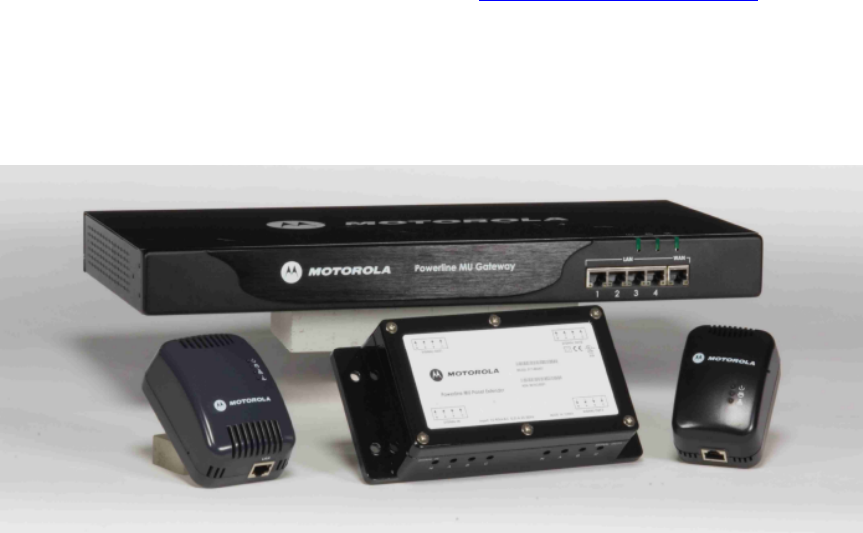
Powerline MU User Guide March, 2007
Issue 2.0 Page 94 of 112
11 Technical Specifications
August 2007
Motorola Powerline MU is a new broadband solution that combines the Motorola Canopy®
system with Broadband over Powerline (BPL) technology to deliver broadband services to
homes, businesses and buildings that have been previously underserved or served only at
high cost by other broadband access technologies.
Powerline MU solution allows service providers to deploy and manage a Broadband over
Powerline network for Multi-Dwelling Unit or Multi-Tenant Unit buildings such as apartment
buildings, hotels or retail outlets. Complementing and completing the MOTOwi4 portfolio,
Powerline MU uses Canopy technology as the network backbone. Powerline MU provides
a complete BPL solution from a leading manufacturer.
Please refer to Motorola’s ordering instructions to select equipment best suited for the
customer’s electrical configuration. You can also visit http://www.canopywireless.com for
more information.
Powerline MU Solution
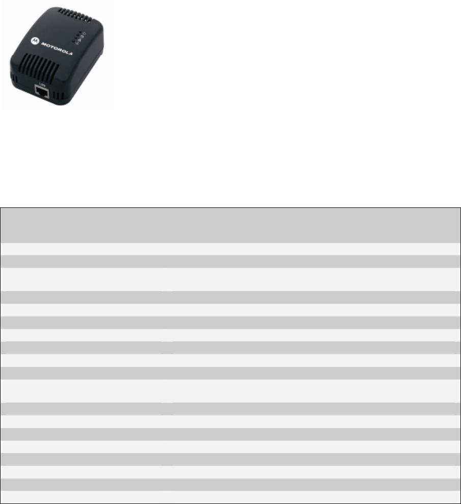
Powerline MU User Guide March, 2007
Issue 2.0 Page 95 of 112
Powerline Modem
• Plugs into a standard AC power outlet to receive Internet signal
• Performs Powerline to Ethernet conversion
• Ethernet output connects to a computer or supplies broadband
input to a home network router or gateway
• Network Address Translation (NAT) for network isolation and
protection
• QoS Support: Maps Ethernet QoS to Powerline QoS using
VLAN priority
• Bandwidth management for service class differentiation
• Subscriber Authentication
• 6-foot Ethernet cable provided
• Additional plug types available upon request
Part Number Type A (US) Plug: 0171486N01
Type C Plug: 0171486N03
Type G Plug: 0171486N14
Product Name Motorola Powerline Modem
Description Customer Premise Equipment in a Powerline MU solution
Modulation Type: OFDM, QAM 256/64/16, DQPSK, DBPSK and ROBO mode
(FSK)
Power Input: 100 – 240 VAC, 50/60 Hz
Power Consumption 7 Watts
Network Management: SNMP v2c
Powerline Interface HomePlug v 1.01 Turbo
Data Interface Ethernet IEEE 802.3 10/100 Base T
Powerline Encryption 56 bit DES
Network Security Firewall/NAT
Connectors RJ45, Input power/PLC, plug Type A, C, or G plugs available
(other plug types available on demand)
LED Status Lights Power on, Powerline, Ethernet, Authentication
Dimensions 1.6 in. x 2.6 in. x 3.75 in. (4.1 cm x 6.6 cm x 9.5 cm)
Weight .394 lbs (178.6 g)
Operating temperature: 0°C to 50°C (32°F to 122°F)
Safety UL/cUL/CE/CB
Industry Canada ICES-003 Class B
EN EN55022 CE 0682 Class B
FCC Part 15 Class B
Available Now!
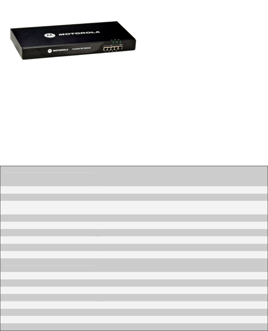
Powerline MU User Guide March, 2007
Issue 2.0 Page 96 of 112
Powerline MU Gateway
• Injects the Internet signal into the
building’s electric distribution
• Performs Ethernet to Powerline
conversion
• Ethernet input connects to Canopy
Subscriber Module or other broadband
source
• Four port Ethernet Switch
• Three Powerline outputs connect to
three electrical phases via capacitive
coupling cables (3 feet in length)
• QoS Support: Maps Ethernet QoS to Powerline QoS using VLAN priority
• Bandwidth management for service class differentiation
• Using BAM (Bandwidth Authentication Manager) provides authentication for associated
Powerline Modems within its network
• Plugs into a standard AC power outlet with 6 foot power cord
• Additional plug types available upon request
Part Number Type A (US) Plug: 0171486N11
Type C Plug: 0171486N04
Type G Plug: 0171486N19
Product Name Motorola Powerline MU Gateway
Description Head End Controller Equipment in a Powerline MU solution
Modulation Type: OFDM, QAM 256/64/16, DQPSK, DBPSK and ROBO mode
(FSK)
Power Input: 100 – 240 VAC, 50/60 Hz
Power Consumption: 7 Watts
Network Management: SNMP v2c
Powerline Interface HomePlug v 1.01 Turbo
Data Interface Ethernet IEEE 802.3 10/100 Base T
Powerline Encryption 56 bit DES
Connectors 5 RJ45, 3 AC coupling connections, Input power (plug Types
A, C, G available)
LED Status Lights WAN, 4 LAN, Power on, PLC, Collision
Dimensions 1.75 in. x 17.3 in. x 7.98 in. (4.44 cm x 44.0 cm x 20.3 cm)
Weight 5.99 lbs (2715 g)
Operating temperature: 0°C to 50°C (32°F to 122°F)
Safety UL/cUL/CE
Industry Canada ICES-003 Class B
EN EN55022 CE 0682 Class B
FCC Part 15 Class B
Available Now!
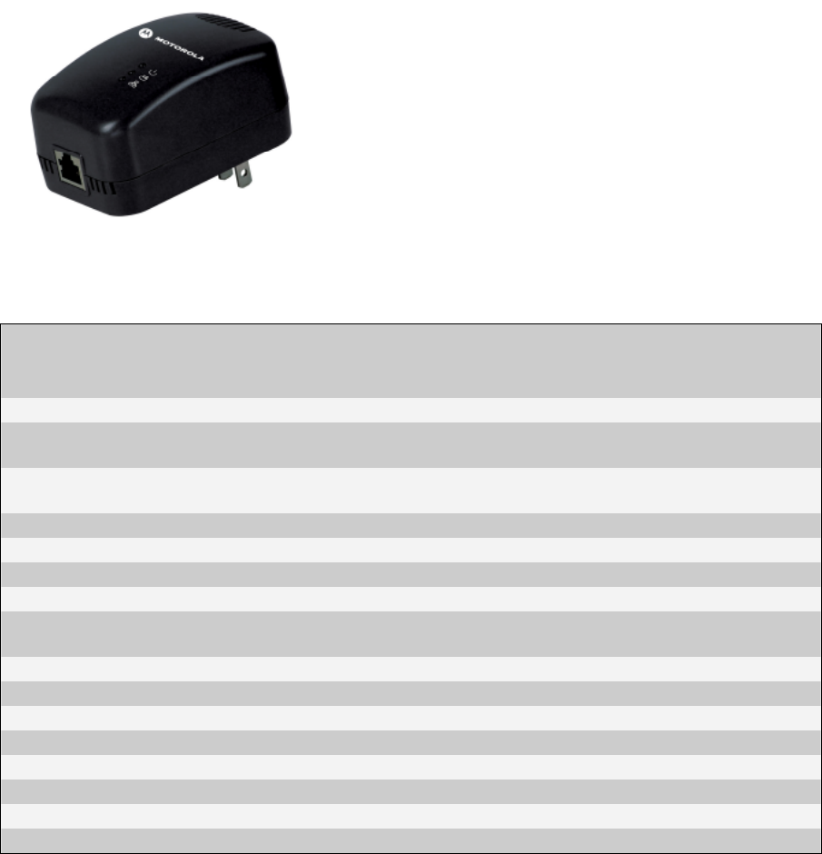
Powerline MU User Guide March, 2007
Issue 2.0 Page 97 of 112
Powerline MU Adapter Available Now!
• Used in pairs
• One Adapter converts data from an Ethernet source
to Powerline and transports over telephone wiring
to a second Adapter that converts data back to
Ethernet to deliver to the Gateway
• Provides greater flexibility for connecting Powerline
MU Gateway(s) to the primary internet access point
• Plugs into a standard AC power outlet (US plug
pictured, Type C plug also available)
• Additional plug types available upon request
Part Number US Plug: 0171486N02
C-Type Plug: 0171486N08
G-type Plug: 0171486N25
Product Name Powerline MU Adapter
Description Optional Powerline MU converter between telephone wiring
and Ethernet
Modulation Type: OFDM, QAM 256/64/16, DQPSK, DBPSK and ROBO mode
(FSK)
Power Input: 100 – 240 VAC, 50/60 Hz
Data Interface Ethernet IEEE 802.3 10/100 Base T
Flow Control IEEE 802.3x
Twisted Pair HomePlug v 1.01 Turbo
Connectors 1 RJ45, 1 RJ11, Input power (plug types A-US, C-European
and G available)
LED Status Lights Power on, Powerline, Ethernet
Dimensions 1.8 in. x 2.4 in. x 3.5 in. (4.57 cm x 6.1 cm x 8.89 cm)
Weight .276 lbs (125 g)
Operating temperature: 0°C to 50°C (32°F to 122°F)
Safety UL/cUL/CE
Industry Canada ICES-003 Class B
EN CE Class B
FCC Part 15 Class B
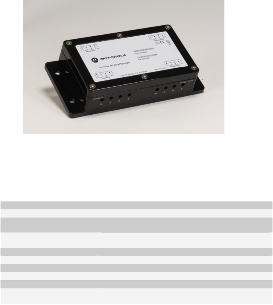
Powerline MU User Guide March, 2007
Issue 2.0 Page 98 of 112
Powerline MU Panel Extender Available Now!
• Useful in mass-metered buildings such as hotels and corporate facilities which have a large
distribution panel that distributes electricity to other smaller breaker panels
• Connect up to three phases from one breaker panel to the Powerline MU Panel Extender
and transmit signal to up to three additional breaker panels
• Provides efficiency in signal distribution while mitigating signal loss
Part Number 0171486N07
Part Name Powerline MU Panel Extender
Description Optional Powerline MU extender to couple up to four breaker
panels together
High Voltage Interface
Up to 277 VAC (phase-neutral), Up to 480 VAC (phase-
phase), Accepts up to 14 AWG wires
Input current 1 mA @ 50/60 Hz
Connectors 4 blocks of 4-pin terminals, 1 block per electrical panel
Dimensions 1.8 in. x 7.9 in. x 3.8 in. (4.5 cm x 20 cm x 9.6 cm)
Weight .85 lbs (385 g)
Operating temperature: 0°C to 50°C (32°F to 122°F)
Safety CE/
UL authorization (In conjunction with Powerline MU Gateway)
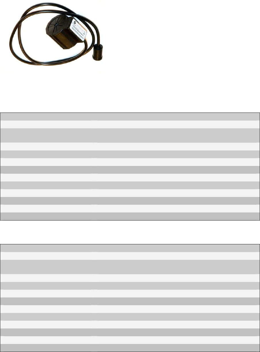
Powerline MU User Guide March, 2007
Issue 2.0 Page 99 of 112
Powerline MU Inductive Coupler
• Useful in individually-metered and multiple
transformer buildings such as apartments and
condominiums which have one or more meter
banks with meters that monitor power
consumption to individual residences
• Connect one coupler per phase just before the
meter bank in the Termination Cabinet over the
insulated portion of the electric cable
• Provides efficiency in signal distribution by
injecting on the larger wires just before the meter bank and subsequent branching to
individual residences with no contact to the actual metal conductor
• Three coupler sizes to accommodate various wiring gauges
500
Part Number 0171486N21
Part Name Powerline MU Inductive Coupler 500
Description Optional Powerline MU coupler to Induce Signal onto in-
building cables before the Meter Bank.
High Voltage Interface Fits up to 500 MCM cable rated 380A
Cable 75 Ohm Coaxial
Connectors F-Connector (Coaxial)
Center Conductor 600v rated 22-gauge stranded copper THHN wire
Dimensions 2.8 in x 2.3 in x 2.2 in (70.14 mm x 58.3 mm x 55mm)
Inner Diameter of core 1 in (25.4 mm)
Outer Diameter of Core 2.02 in (51.31 mm)
Weight .90 lbs
Operating temperature -40°C to 55°C (-40°F to 131°F)
Safety UL authorization (In conjunction with Powerline MU Gateway)
250
Part Number 0171486N23
Part Name Powerline MU Inductive Coupler 250
Description Optional Powerline MU coupler to Induce Signal onto in-
building cables before the Meter Bank.
High Voltage Interface Fits up to 250 MCM cable rated 255A
Cable 75 Ohm Coaxial
Connectors F-Connector (Coaxial)
Center Conductor 600v rated 22-guage stranded copper THHN wire
Dimensions 2.8 in x 2.3 in x 2.2 in (70.14 mm x 58.3 mm x 55mm)
Inner Diameter of core .76 in (19.4 mm)
Outer Diameter of Core 2.02 in (51.31 mm)
Weight .99 lbs
Operating temperature -40°C to 55°C (-40°F to 131°F)
Safety UL authorization (In conjunction with Powerline MU Gateway)
Powerline MU User Guide March, 2007
Issue 2.0 Page 100 of 112
100
Part Number 0171486N22
Part Name Powerline MU Inductive Coupler 100
Description Optional Powerline MU coupler to Induce Signal onto in-
building cables before the Meter Bank.
High Voltage Interface Fits up to 2/0 AWG cable rated at 175A
Cable 75 Ohm Coaxial
Connectors F-Connector (Coaxial)
Center Conductor 600v rated 22-guage stranded copper THHN wire
Dimensions 2.8 in x 2.3 in x 2.2 in (70.14 mm x 58.3 mm x 55mm)
Inner Diameter of core .55 in (14 mm)
Outer Diameter of Core 2.02 in (51.31 mm)
Weight 1.05 lbs
Operating temperature -40°C to 55°C (-40°F to 131°F)
Safety UL authorization (In conjunction with Powerline MU Gateway)
Inductive Coupler Sizes
Column A lists the American Wire Gauge sizes, Column B lists Metric Wire Gauge sizes, and
Column C measures the outer diameter of the electric wire installed in the building. Use that
information to choose the recommended Powerline MU Inductive Coupler from Column D. Column
E lists the inner diameter (the ferrite core) of the Powerline MU Inductive Coupler.
A
Conductor Size
(American Wire
Gauge)
B
Conductor Size
(Metric Wire
Gauge, mm2)
C
Approx Conductor
Outer Diameter With
Insulation (mm)
D
Recommended
Powerline MU
Inductive Coupler
E
Powerline MU
Coupler Inner
Diameter (mm)
- 400 30.1 750* 31
750 MCM - 29.4 750* 31
700 MCM - 28.5 750* 31
600 MCM - 26.7 750* 31
300 26.5 750* 31
500 MCM - 24.9 500 25.4
- 240 24.2 500 25.4
400 MCM - 22 500 25.4
- 185 21.1 500 25.4
350 MCM - 20.6 500 25.4
300 MCM 150 18.5 500 19.4
250 MCM - 17.8 250 19.4
- 120 17.5 250 19.4
4/0 - 16 250 19.4
- 95 15.4 250 19.4
3/0 - 14.7 250 19.4
- 70 13.7 100 14
2/0 - 13.5 100 14
1/0 - 12.2 100 14
- 50 12 100 14
* Powerline MU Inductive Coupler 750 will be available Q4 2007.

Powerline MU User Guide March, 2007
Issue 2.0 Page 101 of 112
Appendix A International Electric Grid Plug Types
International Electric Grid and Plug Types
COUNTRY VOLTAGE FREQUENCY PLUG COMMENTS
Afghanistan 20 V 50 Hz C & F *
* A UN correspondent reports C and F
common in Kabul, but its likely a variety of
plugs may be used around the country.
Some sources report Type D also in use.
Other reports indicate voltage variances
from 160V to 280V.
Albania 220 V* 50 Hz C & F *Voltage variations common
Algeria 230 V 50 Hz C* & F
*A variation of Type C with a ground post offset about
1/2-inch from center may also be found.
American Samoa 120 V 60 Hz A, B, F & I
Andorra 230 V 50 Hz C & F
Angola 220 V 50 Hz C
Anguilla 110 V 60 Hz
A (maybe
B)
Antigua 230 V* 60 Hz A & B *Airport area is reportedly Antigua power is 110 V.
Argentina 220 V 50 Hz C & I*
*Neutral and line wires are reversed from
that used in Australia and elsewhere. Click
here for more.
Armenia 220 V 50 Hz C & F
Aruba 127 V* 60 Hz A, B & F *Lago Colony 115V
Australia 240 V 50 Hz I
*Outlets typically controlled by adjacent
switch. Click here for more.
Austria 230 V 50 Hz F Type C may be found, but rare.
Azerbaijan 220 V 50 Hz C, F
Azores 220 V* 50 Hz B, C, & F *Ponta Delgada 110 V; to be converted to 220 V
Bahamas 120 V 60 Hz A & B
Bahrain 230 V* 50 Hz* G *Awali 110 V, 60 Hz
Balearic Islands 220 V 50 Hz C & F
Bangladesh 220 V 50 Hz A, C, D, G & K
Barbados 115V 50 Hz A, B
Belarus 220 V 50 Hz C & F
Belgium 230 V 50 Hz E
Notes from correspondents: a 'C' style plug can be used
with 'E' and 'F' receptacles. All double-insulated
appliances are indeed fitted with a 'C' plug, and can be
used in any compatible receptacle (C E F and narrow L).
Type C receptacles are prohibited in Belgium.
Belize 110/220 V 60 Hz B & G
Benin 220 V 50 Hz E
Bermuda 120 V 60 Hz A & B

Powerline MU User Guide March, 2007
Issue 2.0 Page 102 of 112
Bhutan 230 V 50 Hz D, F, & G
Type M plugs also identified by some
sources.
Bolivia 220/230 V* 50 Hz A & C *La Paz & Viacha 115V
Bosnia 220 V 50 Hz C & F
Botswana 231V 50 Hz M Type G may be found, but rare.
Brazil 110/220 V* 60 Hz A & B, C
*127 V found in states of Bahia, Paraná (including
Curitiba), Rio de Janeiro, São Paulo and Minas Gerais
(though 220 V may be found in some hotels). Other
areas are 220 V only, with the exception of Fortaleza (240
V). Outlets (click for more) are often a combination of
type A and C and can accept either type plug.
Brunei 240 V 50 Hz G
Bulgaria 230 V 50 Hz C* & F*
*Outlets are reported as type F, though both type C and F
plugs may be encountered.
Burkina Faso 220 V 50 Hz C & E
Burundi 220 V 50 Hz C & E
Cambodia 230 V 50 Hz A & C*
*Some outlets are a combination of type A and C and can
accept either type plug. Plug G may be found in some
hotels.
Cameroon 220 V 50 Hz C, E
Canada 120 V 60 Hz A & B
Canary Islands 220 V 50 Hz C, E, & L
Type L plugs/outlets may have different pin spacing. The
smaller and closer pins are for a rated current of 10 A, the
bigger and wider pins are for a rated current of 16 A.
Cape Verde 220 V 50 Hz C & F
Cayman Islands 120 V 60 Hz A & B
Central African
Republic 220 V 50 Hz C & E
Chad 220 V 50 Hz D, E & F
Channel Islands 230 V 50 Hz G
Chile 220 V 50 Hz C & L
China, People's
Republic of 220 V 50 Hz A, I, G
The "official" plug type is like type A but slightly shorter
and without holes in blades. Type A and I outlets are
common, and Type G might also be found. Click here for
photos and more info.
Colombia 110 V 60 Hz A & B
Comoros 220 V 50 Hz C & E
Congo, People's
Rep. of 230 V 50 Hz C & E
Congo, Dem.
Rep. of (former
Zaire) 220 V 50 Hz C & D
Cook Islands 240 V 50 Hz I
Costa Rica 120 V 60 Hz A & B
Côte d'Ivoire 220 V 50 Hz C & E

Powerline MU User Guide March, 2007
Issue 2.0 Page 103 of 112
(Ivory Coast)
Croatia 230 V 50 Hz C & F
Cuba 110/220 V 60 Hz
A & B, C,
F & L
Most older hotels 110 V. Some newer hotels 220 V.
Some outlets are a combination of type A and C and can
accept either type plug.
Cyprus 240 V 50 Hz G
Czech Republic 230 V 50 Hz E
Denmark 230 V 50 Hz C & K
Denmark's connectors have slight differences from those
used elsewhere. While pin diameter and spacing is
standard, outlets may have different housing depths
which could interfere with standard adaptors -- one report
says this is due to "childproofing." Also, Plug C fits into K-
type outlets (but not vice versa).
Djibouti 220 V 50 Hz C & E
Dominica 230 V 50 Hz D & G
Dominican
Republic 110 V 60 Hz A Type J may exist in some hotels.
East Timor 220 V 50 Hz C, E, F, I,
A UN correspondent reports "power is poor in the country
with frequent brownouts and blackouts. I suspect that
surges are frequent as we go through a lot of surge-
protecting power bars." Further he reports than Type I is
common as much construction is done by Australians;
type C is common in building built during Indonesian
occupation; type E is less common; type F is common in
offices but not hotels.
Ecuador 120-127 V 60 Hz A & B
Egypt 220 V 50 Hz C
El Salvador 115V 60 Hz A & B
England (See
United Kingdom)
Equatorial Guinea 220 V* 50 Hz C & E
*Voltage varies between 150 & 175V with frequent
outages
Eritrea 230 V 50 Hz C
Estonia 230 V 50 Hz F Type C may be found in older buildings. Type E plugs
may work in either C or F type outlets.
Ethiopia 220 V 50 Hz D, J, & L
Faeroe Islands 220 V 50 Hz C & K
Falkland Islands 240 V 50 Hz G
Fiji 240 V 50 Hz I
Finland 230 V 50 Hz C & F
France 230 V 50 Hz E
Type C plugs may be found on some appliances, and will
fit the Type E outlet. Type C outlets may be found in
older buildings. Type A may be found in older buildings
but is illegal.
French Guiana 220 V 50 Hz C & E
Gaza 230 V 50 Hz H

Powerline MU User Guide March, 2007
Issue 2.0 Page 104 of 112
Gabon 220 V 50 Hz C
Gambia 230 V 50 Hz G
Georgia 220 V 50 Hz C
Germany 230 V 50 Hz C & F
Ghana 230 V 50 Hz D & G
Gibraltar 240 V 50 Hz C & G
Great Britain (See
United Kingdom)
Greece 220 V 50 Hz C, D, E & F
Greenland 220 V 50 Hz C & K
Grenada
(Windward Is.) 230 V 50 Hz G
Guadeloupe 230 V 50 Hz C, D, & E
Guam 110 V 60 Hz A & B
Guatemala 120 V 60 Hz A, B, G, & I
Guinea 220 V 50 Hz C, F & K
Guinea-Bissau 220 V 50 Hz C
Guyana 240 V* 60 Hz* A, B, D & G
*Inside the capital city of Georgetown, both 120 V and
240 V at either 50 or 60 Hz are found, depending on the
part of the city (50 Hz most common). Actual voltage may
vary from area to area.
Haiti 110 V 60 Hz A & B
Honduras 110 V 60 Hz A & B
Hong Kong 220 V* 50 Hz G, M Type M replaced by Type G but still found.
Hungary 230 V 50 Hz C & F
Iceland 220 V 50 Hz C & F
India 230 V 50 Hz C & D Click here for photos and more info.
Indonesia
127/230
V* 50 Hz C, F & G
*Conversion to 230 V in progress; complete in principal
cities
Iran 230 V 50 Hz C
Iraq 230 V 50 Hz C, D, & G
Ireland (Eire) 230 50 Hz G
Type D once common and may be
occasionally found.
Isle of Man 240 V 50 Hz C & G
Israel 220 V 50 Hz C
Italy 230 V 50 Hz C, F & L
Type L plugs/outlets may have different pin spacing. The
smaller and closer pins are for a rated current of 10 A, the
bigger and wider pins are for a rated current of 16 A.
Both kinds are currently used and comply to the relevant
Italian (CEI) regulations. Some outlets have overlapping
holes to accept either older or newer types.
Ivory Coast (See
Côte d'Ivoire)

Powerline MU User Guide March, 2007
Issue 2.0 Page 105 of 112
Jamaica 110 V 50 Hz A & B
Japan 100 V 50/60 Hz* A, B
*Eastern Japan 50 Hz (Tokyo, Kawasaki, Sapporo,
Yokohoma, and Sendai); Western Japan 60 Hz (Osaka,
Kyoto, Nagoya, Hiroshima)
Jordan 230 V 50 Hz D, F, G & J* *Type C may be found in some hotels.
Kenya 240 V 50 Hz G
Kazakhstan 220 V 50 Hz C
Kiribati 240 V 50 Hz I
Korea, South 220 V 60 Hz C & F*
*Type F likely to be found in offices and
hotels. 110 V power with plugs A & B was
previously used but is being phased out.
Older buildings may still have this, and
some hotels offer both 110 V and 220 V
service.
Kuwait 240 V 50 Hz D* & G
*Type D primarily used for 15A service, Type G primarily
for 13A service..
Laos 230 V 50 Hz A, B, C, E & F
Latvia 220 V 50 Hz C & F
Lebanon 110/220 V 50 Hz A, B, C, D & G
Lesotho 220 V 50 Hz M
Liberia 120 V 60 Hz A & B
Libya 127 V* 50 Hz D *Barce, Benghazi, Derna, Sebha & Tobruk 230 V
Lithuania 220 V 50 Hz C & F
Liechtenstein 230 V 50 Hz J
Luxembourg 220 V 50 Hz C & F
Macau 220 V 50 Hz D & G
Macedonia 220 V 50 Hz C & F
Madagascar 220 V 50 Hz C & E
Madeira 220 V 50 Hz C & F
Malawi 230 V 50 Hz G
Malaysia 240 V 50 Hz G
Maldives 230 V 50 Hz
A, D, G, J, K &
L
Mali 220 V 50 Hz C & E
Malta 240 V 50 Hz G
Martinique 220 V 50 Hz C, D, & E
Mauritania 220 V 50 Hz C
Mauritius 230 V 50 Hz C & G
Mexico 127 V 60 Hz A & B

Powerline MU User Guide March, 2007
Issue 2.0 Page 106 of 112
Micronesia
(Federal States
of) 120 V 60 Hz A & B
Monaco 127/220 V 50 Hz C, D, E F
Mongolia 220 V 50 Hz C & E
Montenegro 220 V 50 Hz C & F
Montserrat
(Leeward Is.) 230 V 60 Hz A & B
Morocco
127/220
V* 50 Hz C & E *Conversion to 220 V only underway
Mozambique 220 V 50 Hz C, F & M*
*Type M found especially near the border with South
Africa, including the capitol, Maputo.
Type G* found primarily in better hotels. Also, many of
major
Myanmar
(formerly Burma) 230 V 50 Hz C, D, F & G* hotels chains are said to have multipurpose outlets, which
will take Australian 3-pin plugs and perhaps other types.
Namibia 220 V 50 Hz M
Nauru 240 V 50 Hz I
Nepal 230 V 50 Hz C & D
Netherlands 230 V 50 Hz C & F
Netherlands
Antilles
127/220
V* 50 Hz A, B, & F
*St. Martin 120 V 60 Hz; Saba &(St. Eustatius 110 V 60
Hz A, maybe B
New Caledonia 220 V 50 Hz F
New Zealand 230 V 50 Hz I
Nicaragua 120 V 60 Hz A
Niger 220 V 50 Hz
A, B, C, D, E &
F
Nigeria 240 V 50 Hz D & G
Northern Ireland
(see United
Kingdom)
Norway 230 V 50 Hz C & F
Okinawa 100 V* 60 Hz A, B & I *Military facilities 120 V
Oman 240 V* 50 Hz G *Voltage variations common
Pakistan 220 V 50 Hz C & D
Palmyra Atoll 120 V 60 Hz A & B
Panama 110 V* 60 Hz A, B *Panama City 120 V
Papua New
Guinea 240 V 50 Hz I
Paraguay 220 V 50 Hz C
Peru 220 V* 60 Hz* A, B & C *Talara 110/220 V; Arequipa 50 Hz
Philippines 220 V 60 Hz A, B, C Type A most commonly found.
Poland 230 V 50 Hz C & E

Powerline MU User Guide March, 2007
Issue 2.0 Page 107 of 112
Portugal 230 V 50 Hz C & F
Puerto Rico 120 V 60 Hz A & B
Qatar 240 V 50 Hz D & G
Réunion Island 220 V 50 Hz E
Romania 230 V 50 Hz C & F
Russia 220 V 50 Hz F & C
Type F used in new construction. Type C common in
older structures.
Rwanda 230 V 50 Hz C & J
St. Kitts and Nevis
(Leeward Is.) 230 V 60 Hz D & G
St. Lucia
(Windward Is.) 240 V 50 Hz G
St. Vincent
(Windward Is.) 230 V 50 Hz
A, C, E, G, I &
K
Samoa 230 V 50 Hz I
Saudi Arabia 127/220 V 60 Hz A, B, F & G
Scotland (See
United Kingdom)
Senegal 230 V 50 Hz C, D, E & K
Serbia 220 V 50 Hz C & F
Seychelles 240 V 50 Hz G
Sierra Leone 230 V 50 Hz D & G
Singapore 230 V 50 Hz G
Type A adaptors are widely available from
shops as an extension set of 2 to 5 sets of
sockets; most commonly used for audio
and video equipment.
Slovak Republic 230 V 50 Hz E
Slovenia 220 V 50 Hz C & F
Somalia 220 V* 50 Hz C *Berbera 230 V; Merca 110/220 V
*Grahamstad & Port Elizabeth 250V; also found in King
Williams
South Africa
220/230
V* 50 Hz M** ** Types C & G can also be found in some areas.
Spain 230 V 50 Hz C & F
A correspondent reports that in Barcelona's Barrio Gothic,
voltage is 120 V 60 Hz using Types C & F plugs. Step up
transformers are required to use typical European
devices.
Sri Lanka 230 V 50 Hz D
Sudan 230 V 50 Hz C & D
Suriname 127 V 60 Hz C & F
Swaziland 230 V 50 Hz M
Sweden 230 V 50 Hz C & F

Powerline MU User Guide March, 2007
Issue 2.0 Page 108 of 112
Switzerland 230 V 50 Hz J
Type C plugs are common on appliances,
and will fit the Type J outlet.
Syria 220 V 50 Hz C, E, & L
Tahiti 110/220 V 60 Hz A, B, E
Information is based mainly on hotel experiences
reported by travelers.
Tajikistan 220 V 50 Hz C & I
Taiwan 110 V 60 Hz A, B
Tanzania 230 V 50 Hz D & G
Thailand 220 V 50 Hz A & C*
*Some outlets are a combination of type A and C and can
accept either type plug.
Togo 220 V* 50 Hz C *Lome 127 V
Tonga 240 V 50 Hz I
Trinidad & Tobago 115V 60 Hz A & B
Tunisia 230 V 50 Hz C & E
Turkey 230 V 50 Hz C & F
Turkmenistan 220 V 50 Hz B & F
Uganda 240 V 50 Hz G
Ukraine 220 V 50 Hz C
United Arab
Emirates 220 V* 50 Hz G
*Outlets typically controlled by adjacent switch.
United Kingdom 230 V* 50 Hz G Though nominal voltage has been officially changed to
230 V, 240 V is within tolerances and commonly found.
United States of
America 120 V 60 Hz A & B
Uruguay 220 V 50 Hz C, F, I* & L
Type F becoming more common as a result of computer
use. *Neutral and line wires are reversed from that used
in Australia and elsewhere. Click here for more.
Uzbekistan 220 V 50 Hz C & I
Vanuatu 230 V 50 Hz I
Some Type G may linger from British
Colonial period, but are a rarity.
Venezuela 120 V 60 Hz A & B
Vietnam
127/220
V* 50 Hz A, C & G
*To be standardized at 220 V. Type G
found in newer hotels, primarily those built
by Singaporean and Hong Kong
developers.
Virgin Islands
(British and U.S.) 115V 60 Hz A & B
Wales (See
United Kingdom)
Yemen, Rep. of 220/230 V 50 Hz A, D & G
Zambia 230 V 50 Hz C, D & G
Zimbabwe 220 V 50 Hz D & G
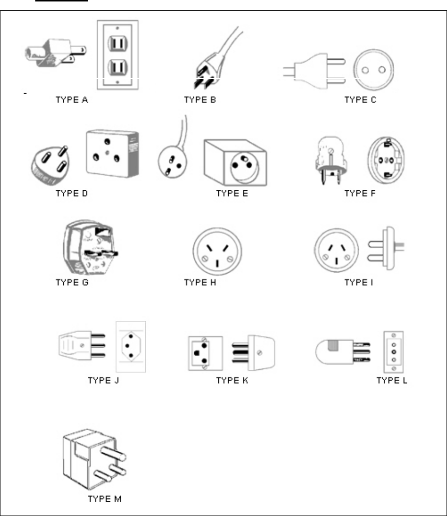
Powerline MU User Guide March, 2007
Issue 2.0 Page 109 of 112
Plug Types
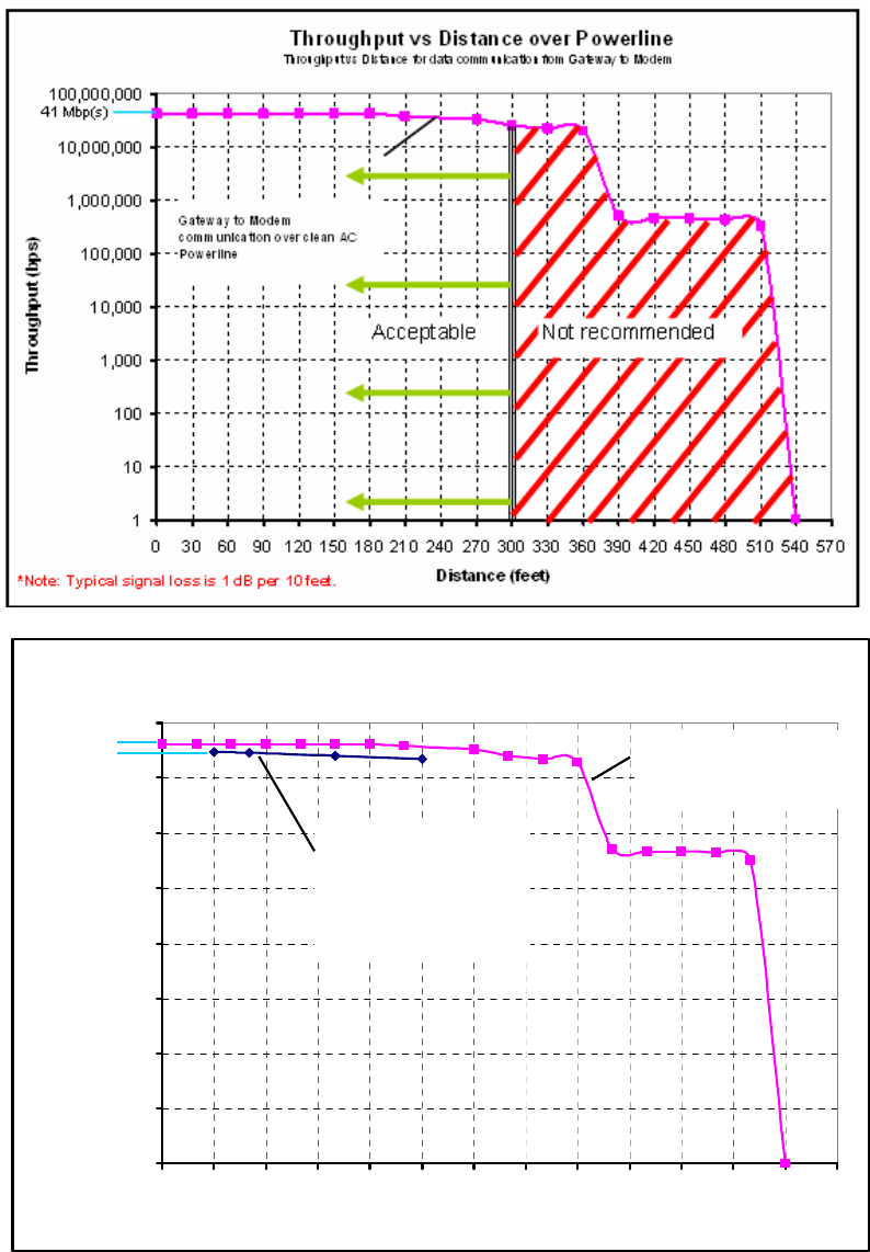
Powerline MU User Guide March, 2007
Issue 2.0 Page 110 of 112
Appendix B Signal Distances
Signal distances will vary based on the age, condition and “noise” on the lines on which the
is being transmitted. The following charts show distances based on ideal conditions with
little or no outside interference. The Powerline MU system is designed to be used in an
indoor environment.
Throughput vs Distance over Coax and Phone Wire
1
10
100
1,000
10,000
100,000
1,000,000
10,000,000
100,000,000
0 300 600 900 1200 1500 1800 2100 2400 2700 3000 3300 3600 3900
Distance (feet)
Throughput (bps)
Throughput vs Distance for data communication from Gateway to Modem
Gateway to Modem Powerline
Communication over Coax
(ideal conditions, no noise)*
Hybrid Adapter Communication
over Phone Wire
(ideal conditions, no noise)*
Hybrid tested to 1500 feet. Greater
distances may be possible.
41 Mbp(s)
33 Mbp(s)
*Note: Typical signal loss is 1.5 dB per 100 feet.
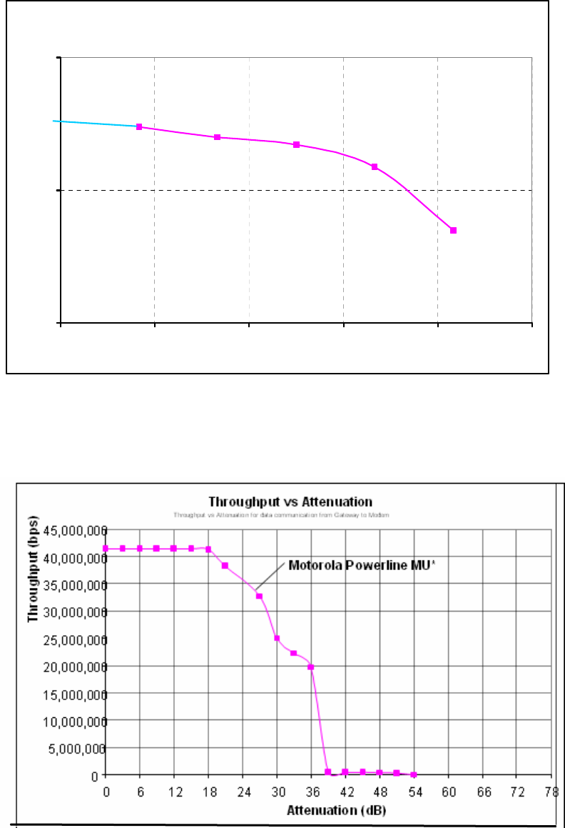
Powerline MU User Guide March, 2007
Issue 2.0 Page 111 of 112
Greater distances may be achieved if the wires are in conduit, reducing the potential for
outside interference.
Note: Typical signal loss is 3 dB per 10 feet minus 1-4 dB insertion loss
(to account for wired connections from Panel Extender to Breaker Panel).
* Represents Maximum throughput with UDP Layer 3 traffic (untagged data packets)
Throughput vs Distance for Panel Extender
1
10
100
0 30 60 90 120 150
Distance (feet)
Throughput (bps)
Throughput vs Distance for data communication from Panel Extenter to Panel Extender using 12-gauge wire
30 Mbp(s)
*Note: Typical signal loss is 3 dB per 10 feet minus 1-4
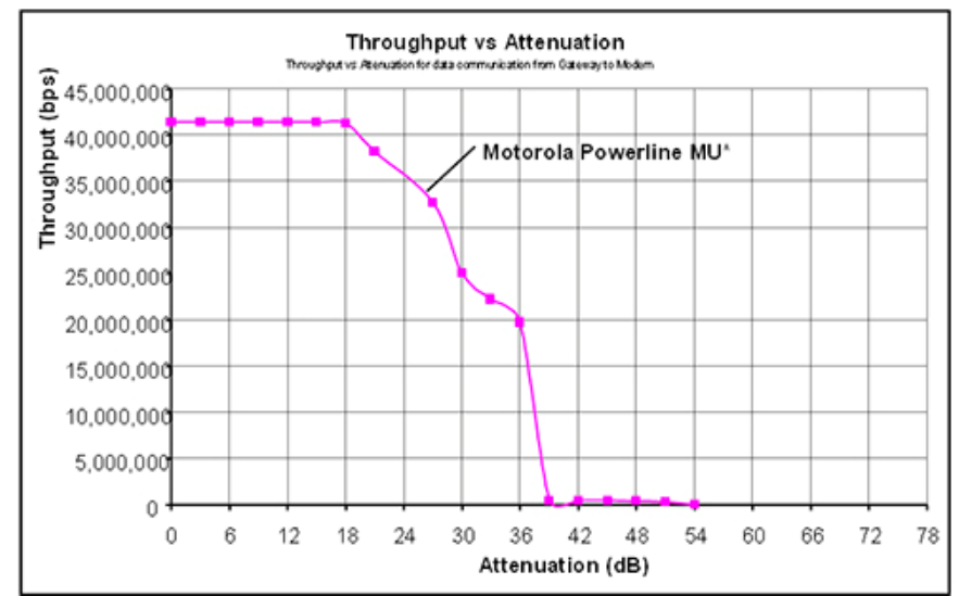
Powerline MU User Guide March, 2007
Issue 2.0 Page 112 of 112
• Signal begins to diminish at around 18dB of attenuation
• Signal drops quickly at 36dB
• Signal is not available after 40dB
* Represents maximum throughput with UDP Layer 3 traffic (untagged data packets)
