Moxa W2004 Wireless Serial Device Server User Manual Part 1
Moxa Inc. Wireless Serial Device Server Part 1
UserManual.wiki
>
Moxa
>
W2004 User Manual
>
User Manual Part 1
Contents
1.
User Manual Part 1
2.
Users Manual Part 2
User Manual Part 1
Navigation menu
Upload a User Manual
Namespaces
Wiki Guide
HTML
PDF
Info
Views
User Manual
Discussion / Help
Navigation


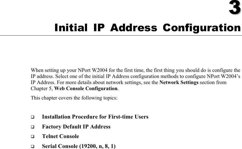

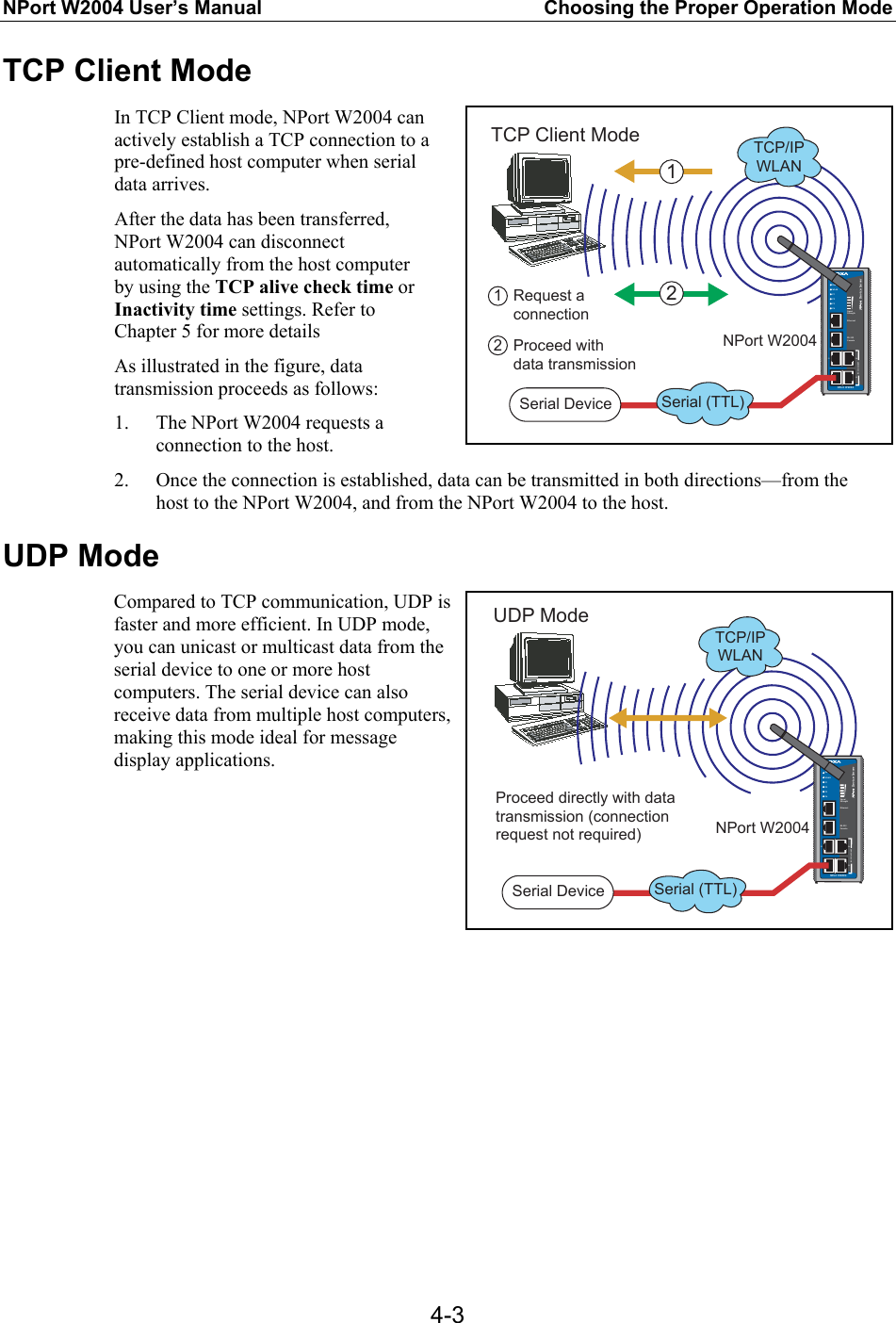
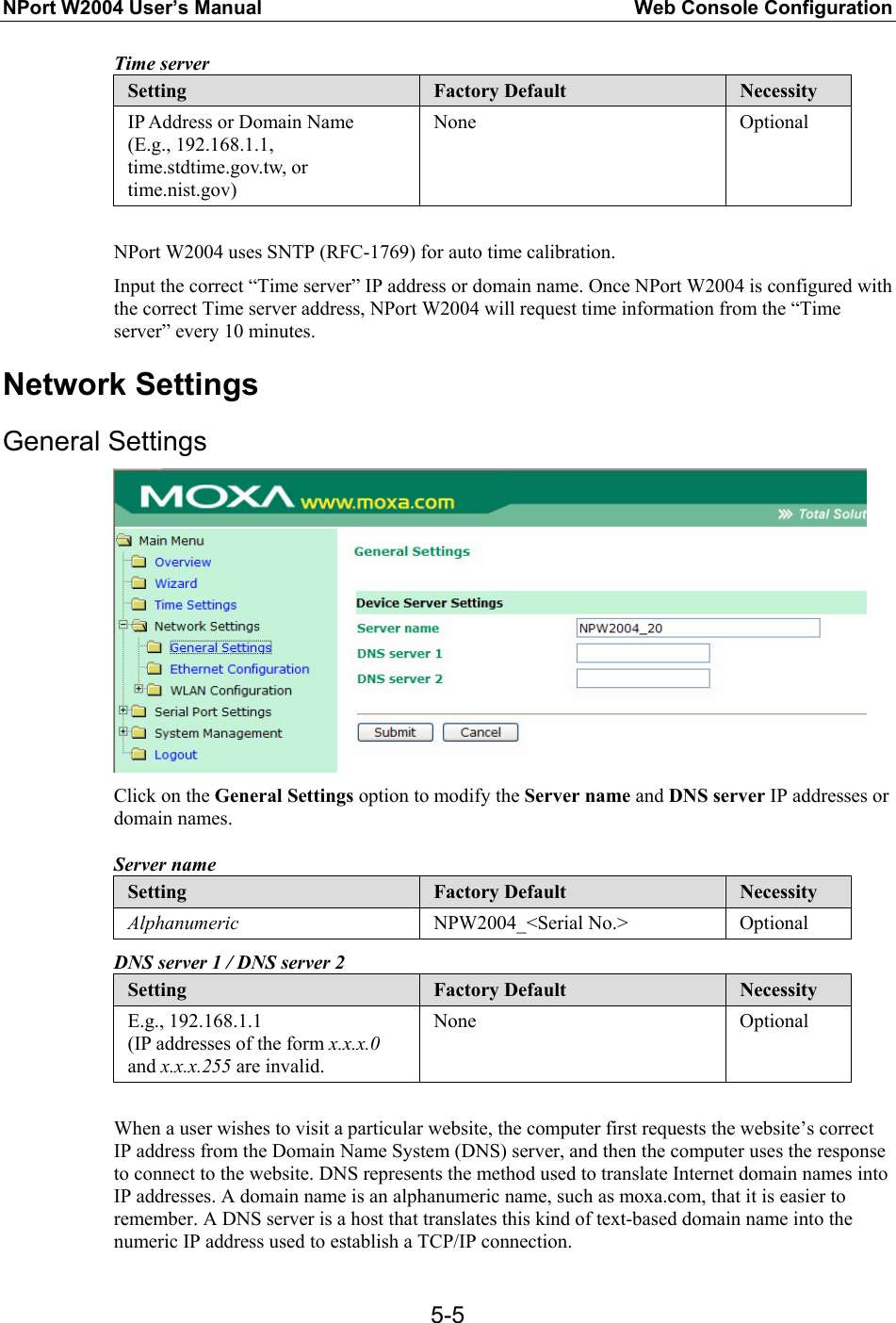
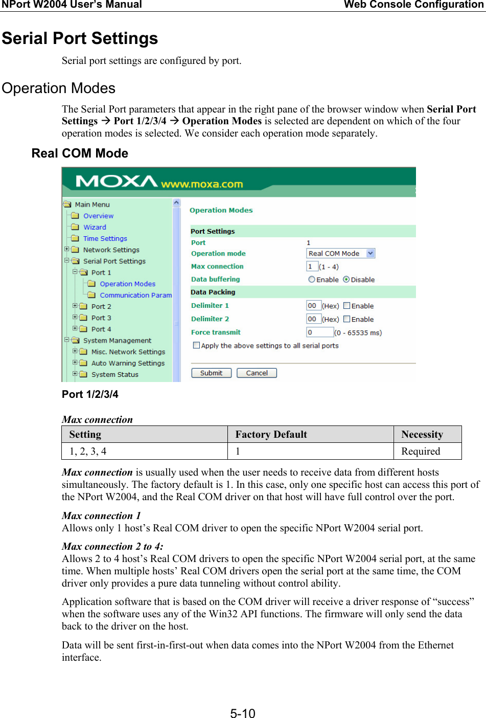
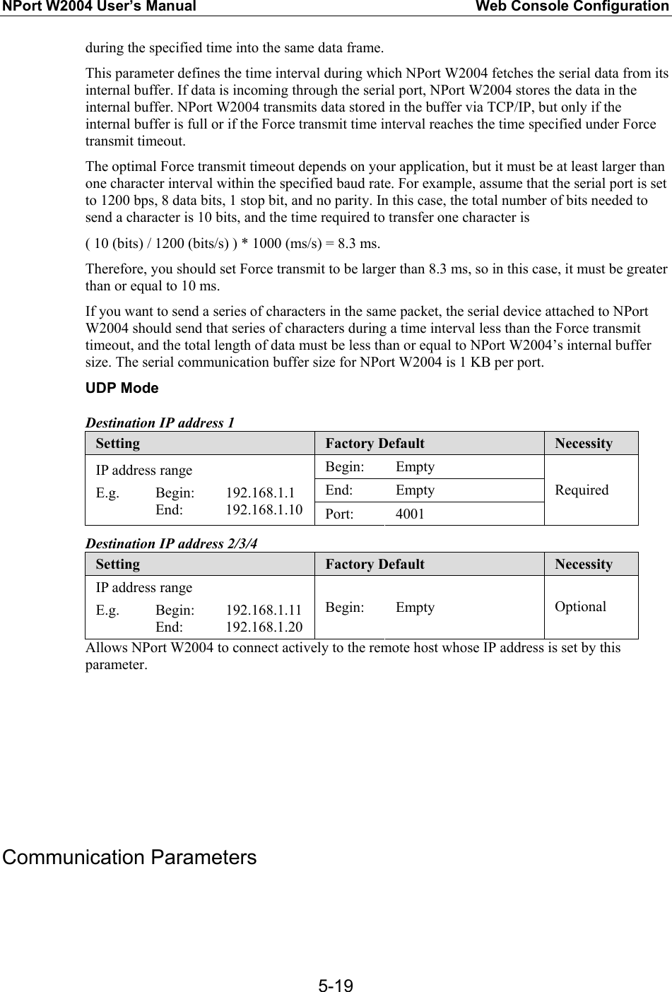
![NPort W2004 User’s Manual Web Console Configuration 5-4Time Settings NPort W2004 has a built-in Real-Time Clock that allows you to add real-time information to functions such as Auto warning “Email” or “SNMP Trap.” ATTENTION First time users should select the time zone first. The Console will display the “real time” according to the time zone compared to GMT. If you would like to modify the real time clock, select “Local time.” NPort W2004’s firmware will modify the GMT time according to the Time Zone. Time zone Setting Factory Default Necessity User selectable time zone GMT (Greenwich Mean Time) Optional Local tim (yy/mm/dd)e Setting Factory Default Necessity User adjustable time (2000/1/1-2037/12/31) GMT (Greenwich Mean Time) Optional Click on the [ Modify ] button to open the Modify time settings window to input the correct local time.](https://usermanual.wiki/Moxa/W2004.User-Manual-Part-1/User-Guide-492972-Page-28.png)