Moxa WAPA003 IEEE 802.11a/b/g miniPCI module User Manual WAPA003 20151228
Moxa Inc. IEEE 802.11a/b/g miniPCI module WAPA003 20151228
Moxa >
Contents
- 1. User Manual rv1
- 2. (WAPA003) UserMan
- 3. User manual
- 4. WAPA003 UserMan 20100804
- 5. (WAPA003) UserMan_20151228
(WAPA003) UserMan_20151228

Moxa
IEEE
802.11
b/g MiniPCI Module
W
A
P
A003
User
’
s
Manual
www
.moxa.com
First Edition, June 2009
2009 Moxa Inc. All rights reserved.
Reproduction without permission is prohibited.

WAPA003
User’s
Manual
The hardware and software described in this manual is furnished under a license agreement and may be used
only in accordance with the terms of that agreement.
Copyright Notice
Copyright
2009 Moxa Inc.
All rights reserved.
Reproduction without permission is prohibited.
Trademarks
MOXA is a registered trademark of Moxa Inc.
All other trademarks or registered marks in this manual belong to their respective manufacturers.
Disclaimer
Information in this document is subject to change without notice and does not represent a commitment on the
part of Moxa.
Moxa provides this document “as is,” without warranty of any kind, either expressed or implied, including, but
not limited to, its particular purpose. Moxa reserves the right to make improvements and/or changes to this
manual, or to the products and/or the programs described in this manual, at any time.
Information provided in this manual is intended to be accurate and reliable. However, Moxa assumes no
responsibility for its use, or for any infringements on the rights of third parties that may result from its use.
This product might include unintentional technical or typographical errors. Changes are periodically made to the
information herein to correct such errors, and these changes are incorporated into new editions of the
publication.
Technical Support Contact Information
www.moxa.com/support
Moxa Americas:
Toll-free: 1-888-669-2872
Tel: +1-714-528-6777
Fax: +1-714-528-6778
Moxa China (Shanghai office):
Toll-free: 800-820-5036
Tel: +86-21-5258-9955
Fax: +86-10-6872-3958
Moxa Europe:
Tel: +49-89-3 70 03 99-0
Fax: +49-89-3 70 03 99-99
Moxa Asia-Pacific:
Tel: +886-2-8919-1230
Fax: +886-2-8919-1231
Table of
Contents
Chapter
1
Introduction
Overview
Features
Specification
Chapter
2
Getting
Started
Module Layout
Block Diagram
Hardware Installation
Software Installation

WAPA003 User’s Manual Introduction
1
Introduction
The following topics are covered in this chapter:
Overview
Features
Specifications

WAPA003 User’s Manual Introduction
Overview
WAPA003 Mini-PCI Module is designed to provide wireless communication for all wireless
device based systems. It communicates via the standard 802.11b/g protocols. The WAPA003
uses the AR5414 wireless chipset from Atheros. This module is connected to the PCI bus
through a Mini-PCI connector and special circuitry to allow for compatibility with either 3.3V or 5V PCI
signaling.
.
Features
All-CMOS single chip for IEEE 802.11b/g compatible WLANs
No external VCOs or SAW filters needed
Baseband in-phase (I) and quadrature (Q) signals, converts them to the desired frequency,
and drives the RF signal off-chip
Integrated low-noise amplifier (LNA)
External PA and/or LNA can be used for special applications
Advanced wideband receiver with best path sequencer for better range and multipath resistance
than conventional equalizer-based designs
Extended tuning range (2.300-2.500) for worldwide use
High speed UART with DMA supports data rates up to 1 Mbps
WAPA003 User’s Manual Introduction
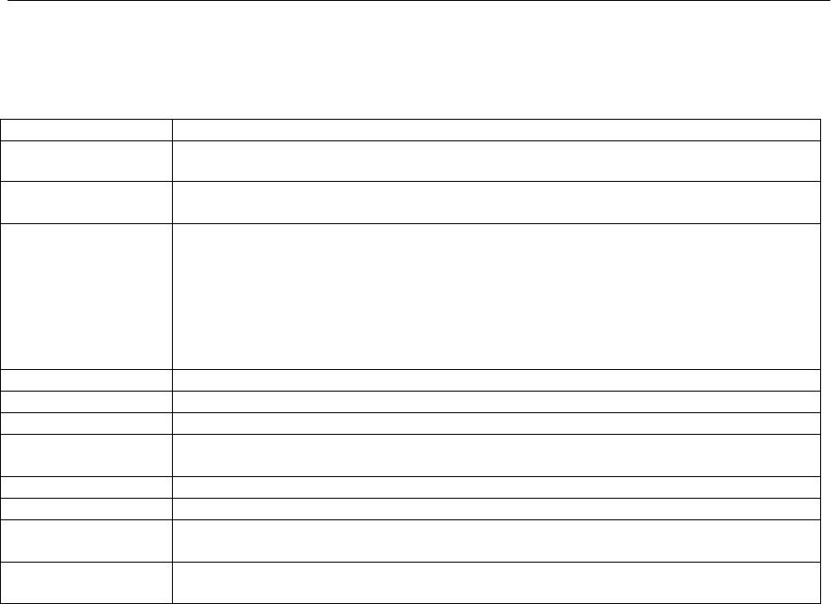
Specification
Features WAPA003
Chi
p
se
t
Atheros AR5414
Receive Sensitivity 802.11b :-84
d
B
m
(typicall
y
)
802.11g : -80dBm(typically)
Baseband
Processor
(BBP)
˙ 802.11
b
suppor
t
rate: 1M, 2M, 5.5M, 11M
b
p
s
˙ 802.11g support rate : 6M, 9M, 12M,18M,24M, 36M, 48M, 54M bps
˙ Modulation scheme: BPSK, QPSK, 16 QAM, 64 QAM, DBPSK,DQPSK, and CCK
˙ 802.11e-compatible bursting
˙ Support for draft IEEE h, i and j standards
˙ Atheros Extended Range feature supported (Turbo Mode), Atheros Super A/G mode
with up to 108 Mbps
security engine WEP64,WEP128, WEP256, AES-CCM, TKIP ,WPS
Bus Interface Mini PCI standard bus co
m
p
lain
t
Connectors Defined BTB connecto
r
is using 2x40
p
ins heade
r
, and Sup
p
ort Mini-PCI standa
r
d
.
Power
r
equi
r
e
m
en
t
1.8V +/-5%
3.3V +/-10%
Di
m
ension 53
m
m
×32
m
m
Weigh
t
15g
O
p
erating
Temperature -40
t
o +80 ℃
Sto
r
age
Temperature: -40
t
o +150℃

2
Getting Started
This chapter covers the module layout, and block diagram, hardware installation of the WAPA003. Software
installation is covered in the next chapter.
The following topics are covered:
Module Layout
Block Diagram
Hardware Installation
Software Installation
WAPA003 User’s Manual Getting Started
Module Layout
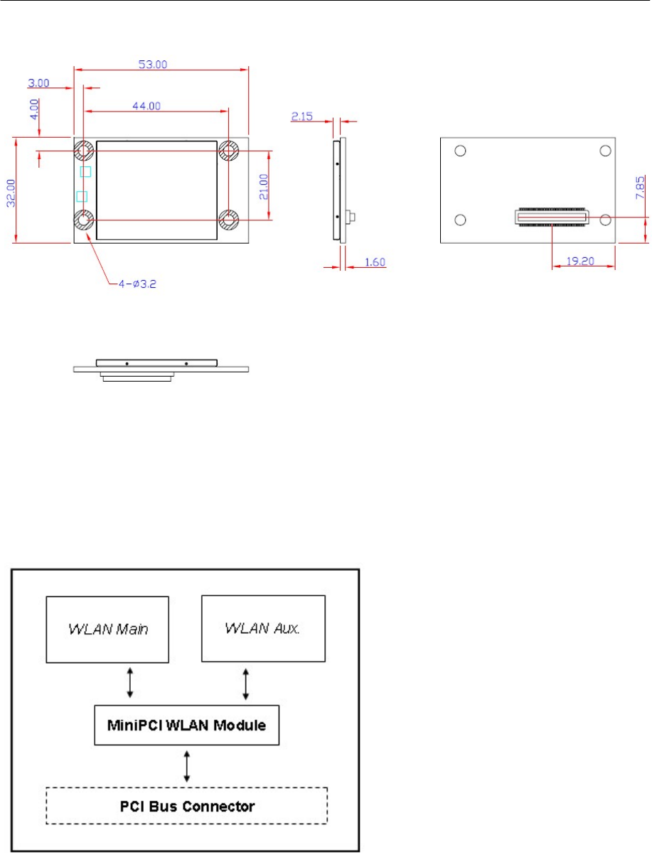
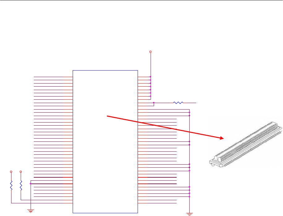
Block Diagram
1. Below is a block diagram of the WAPA003. Primary board components are in bold, while external
connections are italicized.
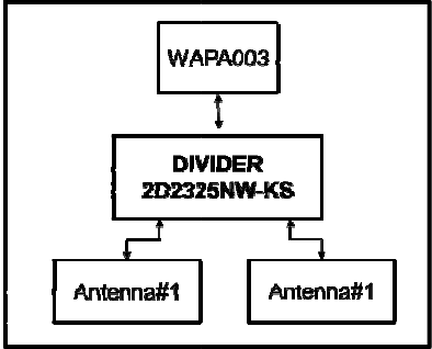
2. Below is a diagram of DIVIDER 2D2325NW-KS. WAPA003 can via divider to share power to 2 antennas.
WAPA0
0
0
3 User’s
M
M
anual Gettin
g
g
Started
WAPA003 User’s Manual Getting Started
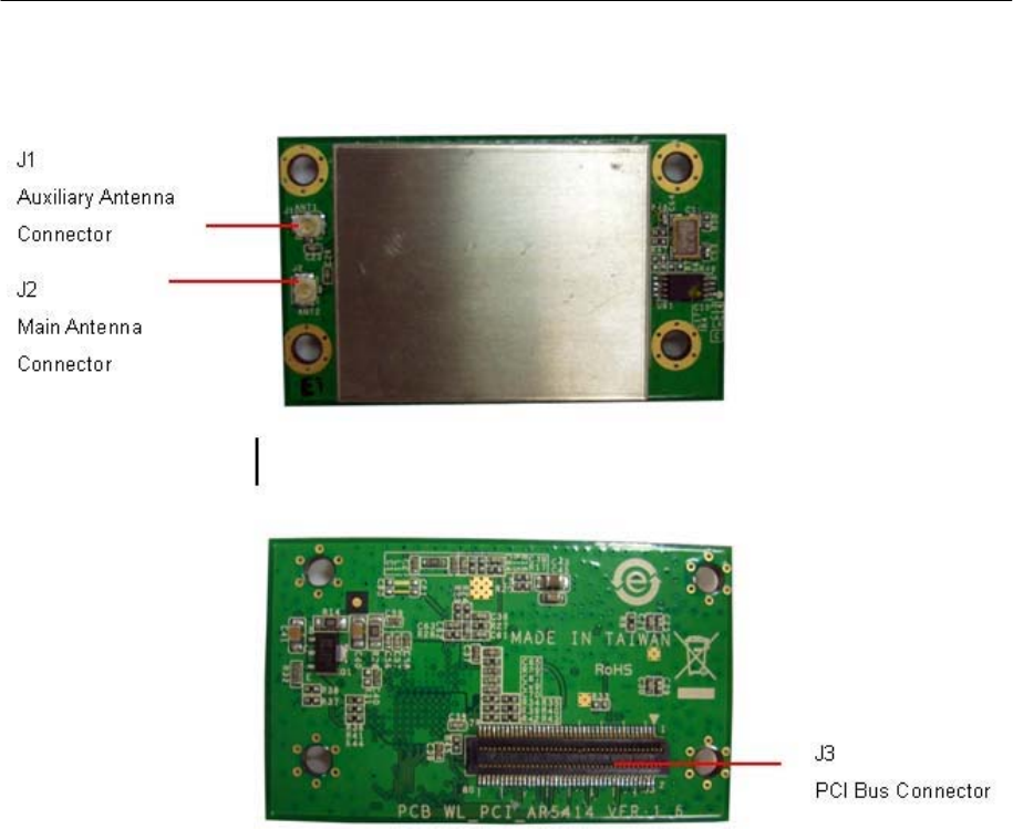
Connector Locations
WAPA003 User’s Manual Getting Started
42
58
66
3
5
7
4
6
8
15 16
24
26
29
31
33
37
30
32
34
38
41
57
59 60
65
71
73
75
72
74
76
MiniPCI Bus Connector PIN Assignments
3.3V_CON
J1
AD0
AD1
AD2
AD3
AD4
1
AD0
AD1
AD2
9
AD3
2
3.3V
3.3V-2
3.3V-3
3.3V-4
10
AD5
AD6
11
AD4
13
AD5
3.3V-5
12
3.3V-6
14
AD7
AD8
AD6
17
AD7
3.3V-7
3.3V-8
18
3.3V_AUX
R26
GPIO_5
AD9
19
AD8
3.3VAUX
20
AD10
21
AD9
3.3VAUX-1
22
AD11
AD12
AD13
23
AD10
25
AD11
27
AD12
GND-11
GND-12
GND-13
28
R
R0402
PCI_RST_L
AD14
AD15
AD16
AD17
AD18
AD19
AD13
AD14
AD15
35
AD16
AD17
AD18
RST#
CLK
CLKRUN#
INTA#
36
REQ#
GNT#
PCI_CLK
PCI_CLKRUN_L
PCI_INT_L
PCI_REQ_L
PCI_GNT_L
PCI_PERR_L
AD20
39
AD19
PERR#
40
AD21
AD22
AD23
43
AD20
45
AD21
47
AD22
GND-14
44
GND-15
46
PAR
48
PCI_PAR
PCI_IRDY
_L
AD24
49
AD23
IRDY
#
50
PCI_TRDY
_L
AD25
AD26
51
AD24
53
AD25
AD26
TRDY
#
52
FRAME#
54
STOP#
PCI_FRAME_L
PCI_STOP_L
AD27
AD28
55
AD27
GND-3
56
3.3V
3.3V
AD29
AD30
AD31
AD28
61
AD29
AD30
GND-4
GND-5
62
SERR#
PCI_SERR_L
PCI_DEVSEL_L
63
AD31
DEVSEL#
64
PCI_IDSEL_L
R9
R8
67
GND
IDSEL
68
PCI_PME_L
187
187
PCI_CBE0_L
69
GND-1
PME#
70
R0603
R0603
PCI_CBE1_L
PCI_CBE2_L
PCI_CBE3_L
MPC I _11
MPC I _12
CBE0#
CBE1#
CBE2#
77
CBE3#
LED1-GRNP
GND-6
GND-7
GND-8
GND-9
78
LED1-GRNN
RF_DISABLE
MPCI_14
79
LED2-Y
ELP
LED2-Y
ELN
80
DEFINE
BOARD
EDGE

WAPA003 User’s Manual Getting Started
Hardware Installation
The WAPA003 can be installed into all Moxa wireless system board series. It can be located
below the CPU.
Step
for
Installation
1. Attach the Main WLAN antenna to connector J1.
2. If using an Auxiliary WLAN antenna, attach it to connector J2.
3. Install the WAPA 003 miniPCI card on the system board. Apply pressure to both bus
connectors and gently press the board onto the stack. The board should slide into the matching
bus connectors. Do not attempt to force the board, as this can lead to bent/broken pins.
4. Screw on the WAPA003 miniPCI card.
5. If any power boards are to be stacked above the WAPA003, install them.
6. Screw on the all the necessary chassis.
Software Installation
After physically installing the WAPA003, your operating system must be configured to recognize
the new system board.
Step
for
Installation
1. Apply power to the system board.
2. Connect system board and PC with Ethernet cable.
3. Open a browser and type: 192.168.127.253 to open the system login webpage.
4. Login the webpage with default password: root in order to verify that all of the hardware is
install properly.
Federal Communication Commission Interference
Statement
This equipment has been tested and found to comply with the limits for a Class B digital device, pursuant to Part
15 of the FCC Rules. These limits are designed to provide reasonable protection against harmful interference in a
residential installation. This equipment generates, uses and can radiate radio frequency energy
and, if not
installed and used in accordance with the instructions, may cause harmful interference to radio communications.
However, there is no guarantee that interference will not occur in a particular installation. If this equipment does
cause harmful interference to radio or television reception, which can be determined by turning the equipment
off and on, the user is encouraged to try to correct the interference by one of the following measures:
- Reorient or relocate the receiving antenna.
- Increase the separation between the equipment and receiver.
- Connect the equipment into an outlet on a circuit different from that to which the receiver is connected.
- Consult the dealer or an experienced radio/TV technician for help.
WAPA003 User’s Manual Getting Started
FCC
Caution:
To assure continued compliance, (example - use only shielded interface cables when connecting to computer or
peripheral devices) any changes or modifications not expressly approved by the party responsible for compliance
could void the user's authority to operate this equipment.
This device complies with Part 15 of the FCC Rules. Operation is subject to the following two conditions: (1)
This device may not cause harmful interference, and
(2) This device must accept any interference received, including interference that may cause undesired operation.
IMPORTANT
NO
TE:
This module is restricted to mobile configuration. To comply with FCC RF exposure compliance requirements,
the antenna used for this transmitter must be installed to provide a separation distance of at least 20 cm from all
persons and must not be co-located or operating in conjunction with any other antenna or
transmitter. This transmitter module must not be co-located or operating in conjunction with any other antenna
or transmitter
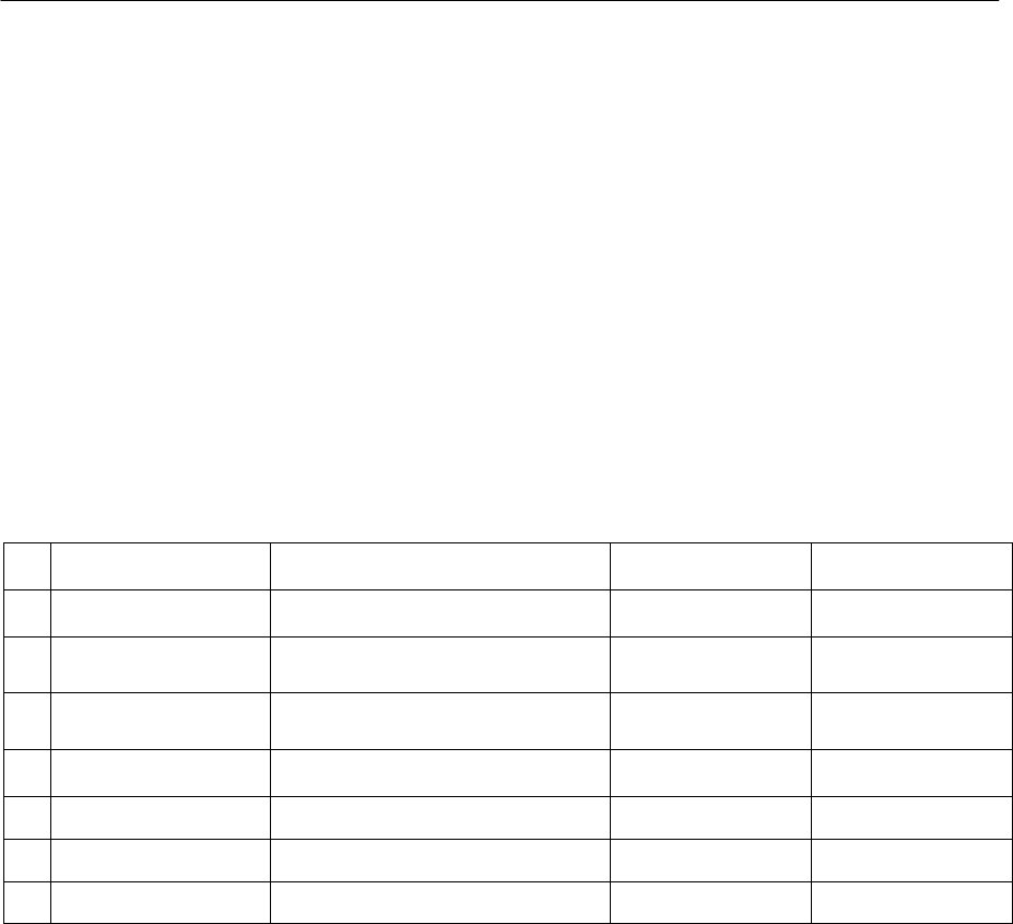
AntennaList
No. Manufacturer Part No. Antenna Type Peak Gain
1 KINSUN SMA-Male-RP (main)(aux) Dipole 2dBi for 2.4GHz
2 KINSUN ANT-WSB-ANM-05
(main)(aux) Dipole 5dBi for 2.4GHz
3 KINSUN ANT-WDB-ANM-0609
(main)(aux) Dipole 6dBi for 2.4GHz
4 Antenna Technology AT1515 Panel 11dBi for 2.4GHz
5 Antenna Technology AT1524 Panel 8dBi for 2.4GHz
6 Antenna Technology AT1539 Panel 14dBi for 2.4GHz
7 DIAMOND TK2632 Panel 14dBi for 2.4GHz
Note:
1. The antenna of EUT conforms to FCC 15.203.
2. Only the higher gain antenna was tested and recorded in this report
3. Addition three new antenna (AT1515, AT1524, AT1539, TK2632), antenna gain is higher with the
original application.
4. No.6 (Antenna Technology / AT1539) and No.7(DIAMOND/ TK2632) are same antennas with
different marketing name.
MoxaAmericasInc.
MoxaCorporatePlaza
601ValenciaAvenue,#100
Brea,California92823
Tel:1‐888‐MOXA‐USA(1‐888‐669‐2872)
+1‐714‐528‐6777
Fax:+1‐714‐528‐6778
Email:usa@moxa.com
Web:www.moxa.com