Mueller Systems CCOM-AC Spread Spectrum Transmitter User Manual
Mueller Systems, LLC Spread Spectrum Transmitter
Contents
- 1. Manual
- 2. User Manual
User Manual

1
CCOMInstallation&OperationManual
880‐0017‐001RevA04
Revision History
Rev Description of change Changed by Effective Date
A00Originated&ReleasedBruggemann04/08
A01UpdatedtoincludeFCCnoticesandlabelsCullinan12/08
A02MinorUpdatesforFCCnoticesandexternalantennaCullinan12/08
A04MinorUpdatesforFCCnoticesforantennaseparation Cullinan1/09

2
MANUFACTURER
ArkionSystems
230UnionStreet
NewBedfordMA,02740
TableofContents
1) Intendeduse……………………………………………………………………………………..4
2) EnvironmentalCaution………………………………………………………………………4
3) Installation&Operation…………………………………………………………………….4
4) Maintenance……………………………………………………………………………………..7
5) Labels&Locations…………………………………………………………………………….7
5.1ExplanationsofLabels&Symbols………………………………………………..8
5.2CCOMLabels……………………………………………………………………………….8
5.3LocationsofCCOMLabels…………………………………………….…………..12
5.4CCOMOrderableEndItems……………………………………………………...14
6) FCCLabels…………………………………………………………………………….15
3
FCCInformation
ChangesormodificationsnotexpresslyapprovedbytheArKionSystemscouldvoidthe
user'sauthoritytooperatetheequipment.
IMPORTANTNOTE:TocomplywithFCCRFexposurecompliancerequirements,the
antennausedforthistransmittermustbeinstalledtoprovideaseparationdistanceofat
least35cmfromallpersonsandmustnotbeco‐locatedoroperatinginconjunctionwith
anyotherantennaortransmitter.
“NOTE:ThisequipmenthasbeentestedandfoundtocomplywiththelimitsforaClassB
digitaldevice,pursuanttoPart15oftheFCCRules.Theselimitsaredesignedtoprovide
reasonableprotectionagainstharmfulinterferenceinaresidentialinstallation.This
equipmentgenerates,usesandcanradiateradiofrequencyenergyand,ifnotinstalledand
usedinaccordancewiththeinstructions,maycauseharmfulinterferencetoradio
communications.However,thereisnoguaranteethatinterferencewillnotoccurina
particularinstallation.Ifthisequipmentdoescauseharmfulinterferencetoradioor
televisionreception,whichcanbedeterminedbyturningtheequipmentoffandon,the
userisencouragedtotrytocorrecttheinterferencebyoneormoreofthefollowing
measures:
‐‐Reorientorrelocatethereceivingantenna.
‐‐Increasetheseparationbetweentheequipmentandreceiver.
‐‐Connecttheequipmentintoanoutletonacircuitdifferentfromthattowhichthereceiveris
connected.
‐‐Consultthedealeroranexperiencedradio/TVtechnicianforhelp.

4
1) IntendedUse:
TheCCOMunitisintendedforindoor&outdooruseasanunattendeddatacollectorfor
automaticmetermetering&controlapplications.Theunitisattached(hardwired)toan
externalpowersource,10‐30VDC,15WfortheCCOM_DC&100‐240VAC ,50/60HZ,
15WforaCCOMAC.Theexternalpowerhookupistomeetappropriatelocal&national
electricalcodes&beperformedbyanappropriatelylicensedprofessional.
ACModel(InputRated100‐240VAC,15W,50/60Hz,‐30C‐+70C)
DCModel(RequiresanexternalDCsourceof10‐30VDC,15W)
2) EnvironmentalCautions:
Theconnectiontoanexternalpowersourceshouldonlybeperformedbytheappropriate
professional,properlylicensedwithinthelocaljurisdiction.OutdoorsCCOMinstallation
shouldonlybeattemptedwhenweatherconditionspermitsafelyaccomplishingthistask.
Thelead‐acidbatteriesutilizedwithinthisproductshouldbedisposedofintheproper
manner.ContactManufacturerfordisposaldetails.
3) CCOMInstallation&Operation:
TheCCOMunitisa7.3”x10.4”x3.7”NEMA4plasticboxwhichcontainsweighsbetween
2.5&7.5lbs(dependinguponoptions).Itdissipatesbetween4watts(standby)&15watts
(worstcasescenario).Typically,theCCOMisfastenedtoatelephonepolewithtwoscrews
andtheninputpowerisattached&applied.
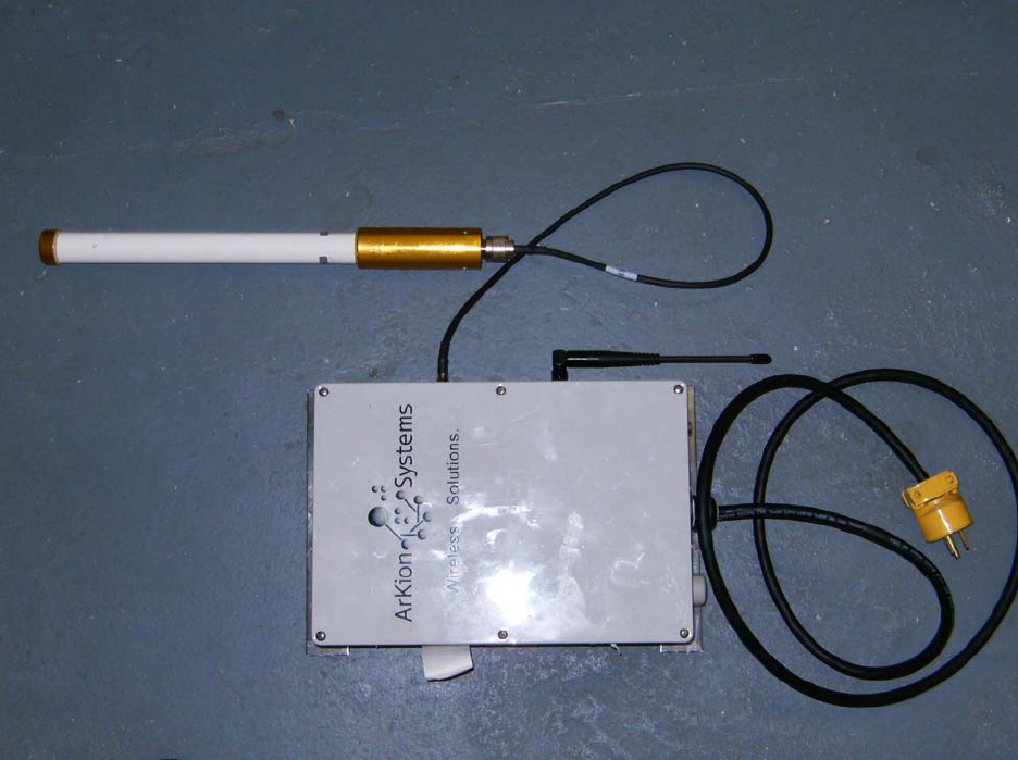
AtypicalCCOMunit,havingbothGPRS(top)&RFDC(bottom)antennasattachedisshown
belowinFigure1.
5
Figure1:CCOMACPWRwithRFDC&GPRSoptions.
TheCCOMpowerinputcanbeeither1030VDC(fortheCCOM_DCDCversion)and
100240VAC50/60HZ(fortheCCOM_ACACversion).Theexternalappearancewillbe
identicalexceptthattheDCversionwillhaveayellowpowercord&theACversionhasa
blackpowercord.Bothversionsalsohaveuniqueexternalstickersidentifyingthetype&
configurationofCCOM.
ThebottomoftheCCOMhasapowercordattachedinthemiddle.Totherightofthatisan
airventandagreenLEDtoindicatethattheunitispoweredup.Ontherightsidearetwo

6
RFantennas.Thetopantenna(inthisexample)isfortheGPRS&thebottomisforthe
RFDC.Apre‐drilledmountingplateisattachedtoboththetop&bottomoftheCCOM.
Therearenoother(operator/installer)accessiblecontrolsordisplays.
AnyuseoftheCCOMproductinotherthantheintendedmannerspecifiedbythe
manufacturermayimpairtheprotectionprovidedbytheequipment.
Installationisachievedasfollows:
InstallationInstructions:
WARNING!Becausetheinstallationistypicallytoatelephonepole,orasimilarhighobject,
andinvolvesconnectingthepowercordtolivepowerlines,onlypersonneltrained&
licensedproperlyforthelocaljurisdictionshouldperformthisinstallation.
A. Pickasafepolelocationwherethepowercordcanreachtheinputpower
source.InstalltheCCOMtothetelephone(orotherwooden)polebyutilizingthe
screws&thepre‐drilledmountingplateslocatedatthetop&bottomofthe
CCOMbox.Keeptheboxvertical/plumbasmuchaspossible.
B. Connectthecolorcodedwirestothepowersource.Thisoperationshouldbe
performedbyaproperlylicensedprofessional.
C. ColorCode:FortheCCOM_AC(hasablackjacketedpowercord),theblackwire
isthepowerinput(nominally110VAC)&thewhitewireisreturn.Forthe
CCOM_DC(hasayellowjacketedpowercord),thewhitewireisthepowerinput
(10‐30VDC)&theblackwireisreturn.
D. Afterconnectinginputpower,verifythatthegreenLEDonthebottomofthe
CCOMislit.
E. Thiscompletesthephysicalinstallation.Fromthistimeforward,additionalsteps
tocontroltheCCOMarealldoneremotelyviatheGPRSRFlink.
4) Maintenance:
TherearenouserserviceableitemswithinaCCOM.Nocleaningisrequired.Thefuses&
batteriesshouldbereplacedbyproperlytrained&licensedpersonnelonly.These

7
replacementsshouldonlybeperformedaftertheunithasbeenremovedfromtheinput
powersourcebypersonneltrained&licensedproperlyforthelocaljurisdiction.Usedfuses
&batteriesshouldbedisposedofproperly.Forallothermaintenanceissuesconsult
manufacturer.
TheCCOMbatterypacksareavailablefromthemanufacturer.These
replacementsshouldonlybeperformedaftertheunithasbeenremovedfrom
theinputpowersourcebypersonneltrained&licensedproperlyforthelocal
jurisdiction,orbythemanufacturer.
TheCCOMfusesarecommerciallyavailable.Thesereplacementsshouldonlybe
performedaftertheunithasbeenremovedfromtheinputpowersourceby
personneltrained&licensedproperlyforthelocaljurisdiction,orbythe
manufacturer.Thefuseratings&CharacteristicsforaCCOM_ACarelisted
below:
o TheBatteryLineFuseisa5Aslowblow250V
01218005.HXP,Littelfuse
o TheCCOM_ACPWBfuse(F3)isa2Afastblow250V
37312000410,Wickman(Littelfuse)
Thefuseratings&CharacteristicsforaCCOM_DCarelistedbelow:
o TheCCOM_DCPWBfuse(F1)isa2Afastblow250V
37312000410,Wickman(Littelfuse)
5)ProductIdentificationandSafetyLabels&Locations
5.1ExplanationofHazardswithRelatedLabelsandSymbols
ServicepersonnelshouldbetrainedtorecognizeunexpectedHAZARDSandto
reactaccordingly.LabelsbelowareusedonCCOMproduct
8
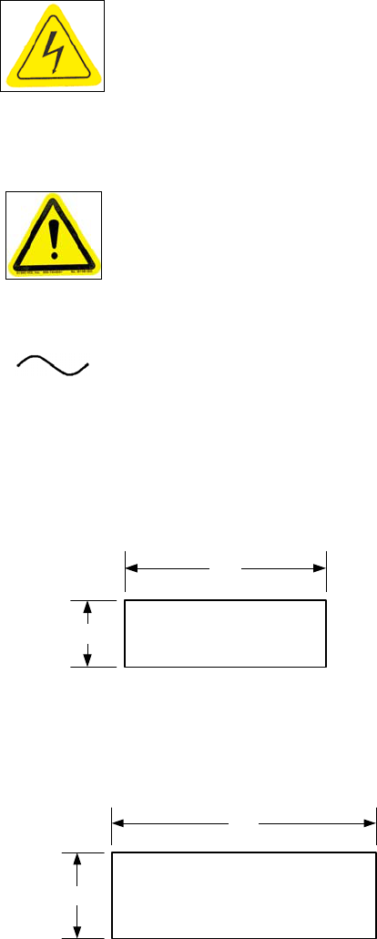
Caution,riskofelectricshock(locatedatShockHazards)
Labelisdefinedas“Caution,refertoManual”
Alternatingcurrent(seerating/modelLabel)
5.2CCOMUnitLabels:
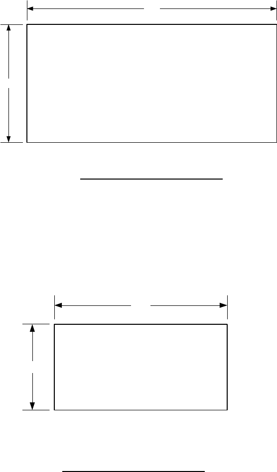
SlowBlowFuse(locatednextto5Afuse)
Use2A,FastBlowFuse(locatednextto2Afuse)
1.75
.50 FUSE RATING 2A
FAST BLOW
1.00
.25 FUSE RATING 5A
SLOW BLOW
9
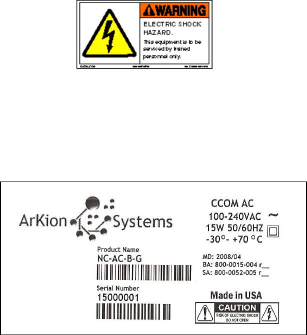
ElectricShockHazardWarning
FinishedGoodsLabel(CCOM,AC,Battery‐backup,GPRSModemshown)
10
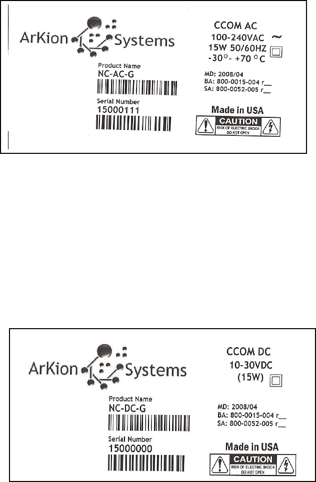
FinishedGoodsLabel(CCOM,AC,GPRSModemshown)
FinishedGoodsLabel(CCOM,DC,GPRSModemshown)
11
BatteryWarningLabels
BATTERYWARNINGLABEL#1
BATTERYWARNINGLABEL#2
DANGER OF EXPLOSION
IF BATTERY IS INCORRECTLY
REPLACED. REPLACE ONLY
WITH THE SAME TYPE
RECOMMENDED BY THE
MANUFACTURER
2.00
1.00
3.00
1.50
BATTERY WARNING
DO NOT SHORT OUT - DO NOT PUT IN FIRE
MAY RELEASE TOXIC MATERIALS OR
CAUSE BURNS
SEALED-LEAD BATTERY MUST BE
RECYCLED OR DISPOSED OF PROPERLY
12
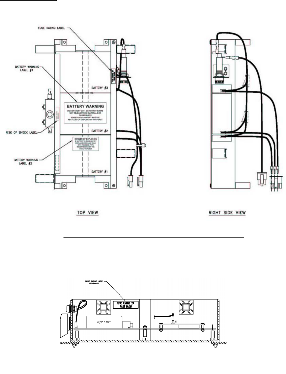
5.3LabelLocations
BatteryWarning,ROS&FuseLabellocationsonBatteryPack
CCOMPWB2AFuseLabellocationinsideenclosure
13
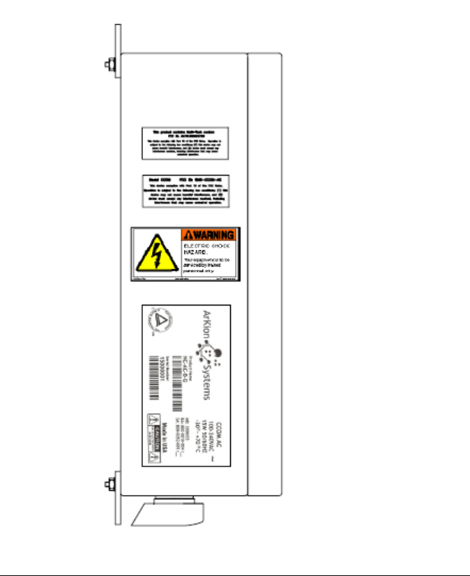
Product&ElectricalShockWarningLabellocationsoutsideenclosure

14
5.4–ArKionSystemsNetworkCollectorOrderableEndItems
NetworkCollector‐CentralCommunicationsModule(CCOM)ProductName
NetworkCollector,ACPower,Back‐upbattery,PhoneModemNC‐AC‐B‐P
NetworkCollector,ACPower,PhoneModemNC‐AC‐P
NetworkCollector,DCPower,PhoneModemNC‐DC‐P
NetworkCollector,ACPower,BatteryBack‐Up,GPRS/GSMModemNC‐AC‐B‐G
NetworkCollector,ACPower,GPRS/GSMModemNC‐AC‐G
NetworkCollector,DCPower,GPRS/GSMModemNC‐DC‐G
NetworkCollector,ACPower,BatteryBack‐up,CDMAModemNC‐AC‐B‐C
NetworkCollector,ACPower,CDMAModemNC‐AC‐C
NetworkCollector,DCPower,CDMAModemNC‐DC‐C
NetworkCollector,ACPower,BatteryBack‐up,EthernetNC‐AC‐B‐E
NetworkCollector,ACPower,EthernetNC‐AC‐E
NetworkCollector,DCPower,EthernetNC‐DC‐E
NetworkCollector,ACPower,BatteryBack‐up,WiFiNC‐AC‐B‐W
NetworkCollector,ACPower,WiFiNC‐AC‐W
NetworkCollector,DCPower,WiFiNC‐DC‐W
NetworkCollector,ACPower,BatteryBack‐up,MaxStreamRadioNC‐AC‐B‐M
NetworkCollector,ACPower,MaxStreamRadioNC‐AC‐M
NetworkCollector,DCPower,MaxStreamRadioNC‐DC‐M
SolarPower,includingsolarpanel,battery,andcharger‐pairwithDCpoweredCCOMNC‐SP

15
6)FCCIdentificationLabels
ThisisillustrationofFCClabelforCCOM.
Figure 1. FCC Label
WhentheCCOMisequippedwithGPRSWAN(WideAreaNetwork)interfacethefollowinglabelis
included
Figure 2. FCC Label
This product contains Module FCC ID: AU792U03G23720
This device complies with Part 15 of the FCC Rules. Operation
is subject to the following two conditions; (1) this device may not
cause harmful interference, and (2) this device must accept any
interference received,
including interference that may cause
Model CCOM FCC ID: SM6-CCOM-
A
C
This device complies with Part 15 of the FCC Rules. Operation
is subject to the following two conditions; (1) this device may not
cause harmful interference, and (2) this device must accept any
interference received, including interference that may cause
undesired operation.