Multi Tech Systems 92U03G23730 GSM Modems User Manual MultiVOIP Gatekeeper Software Guide
Multi Tech Systems Inc GSM Modems MultiVOIP Gatekeeper Software Guide
UserManual.wiki
>
Multi Tech Systems
>
92U03G23730 User Manual
User Guide
Navigation menu
Upload a User Manual
Namespaces
Wiki Guide
HTML
PDF
Info
Views
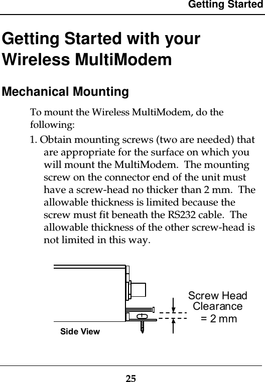
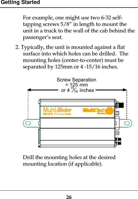
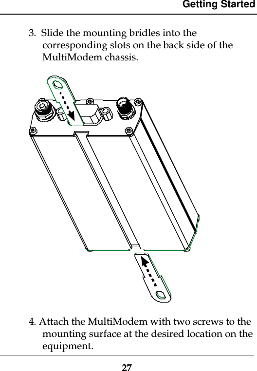
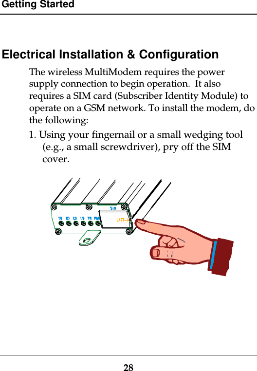
User Manual
Discussion / Help
Navigation