Multi Tech Systems 92U05E06805 Wireless Modem GSM 850/900/1800/1900 MHz User Manual S000304G to EGSM2
Multi Tech Systems Inc Wireless Modem GSM 850/900/1800/1900 MHz S000304G to EGSM2
Contents
- 1. User Guide MTCBA E
- 2. User Guide MTCBA E U
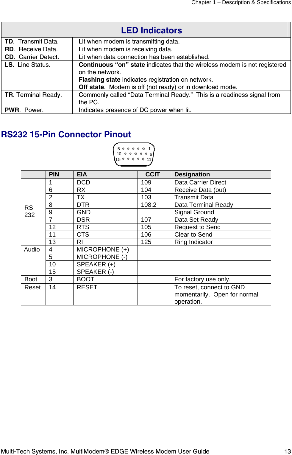
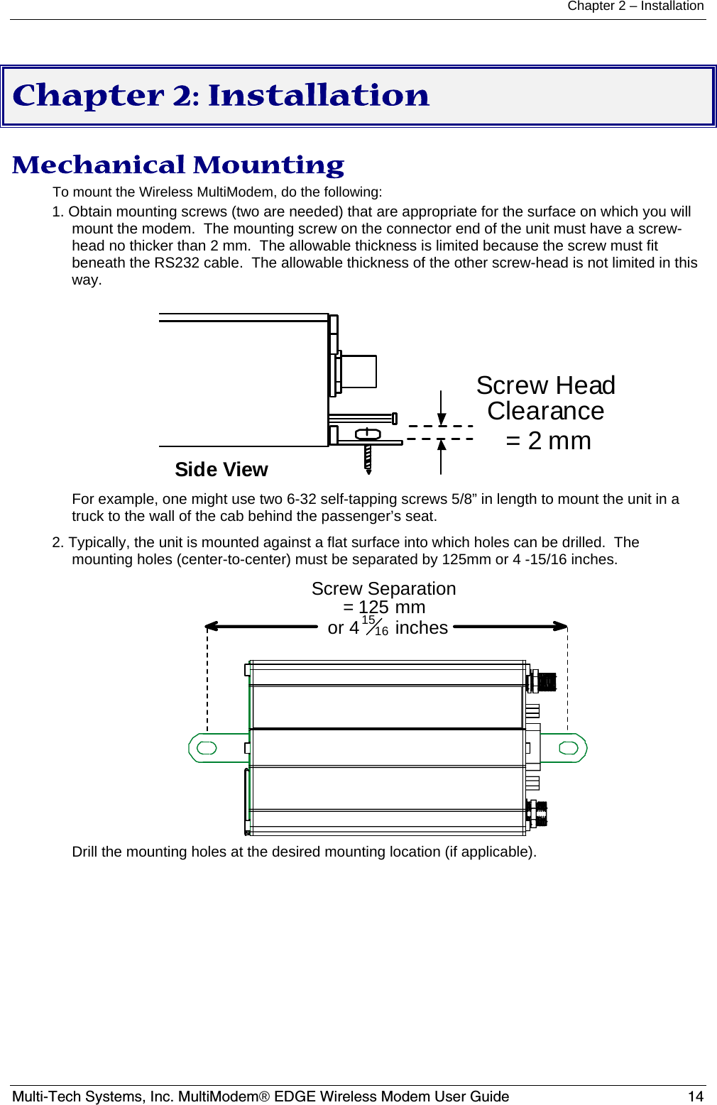
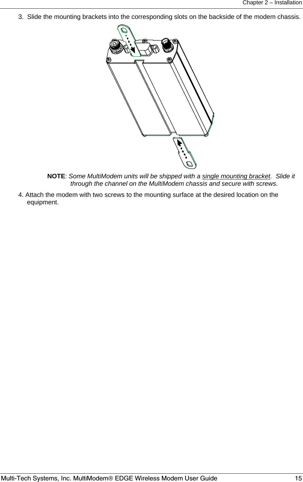
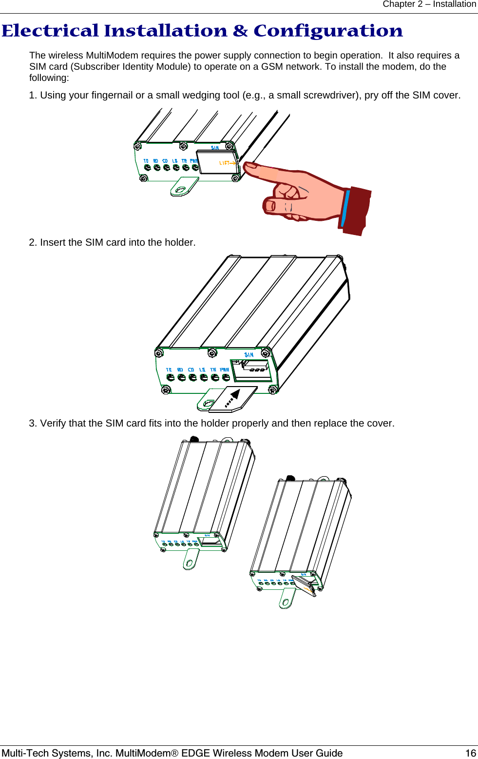
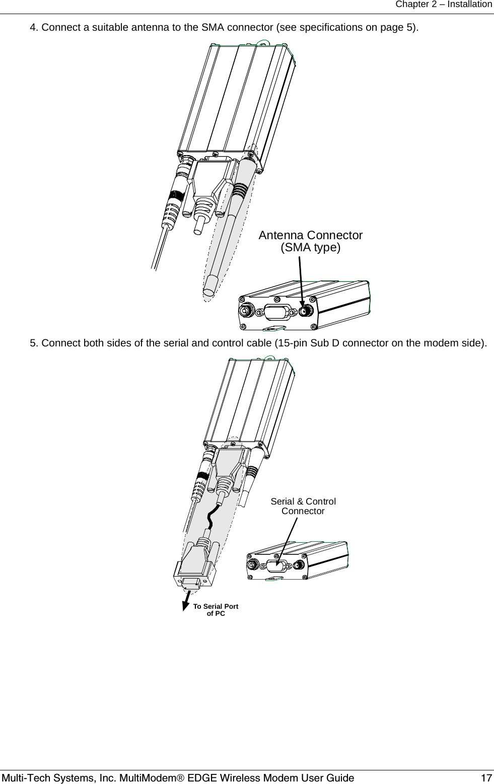
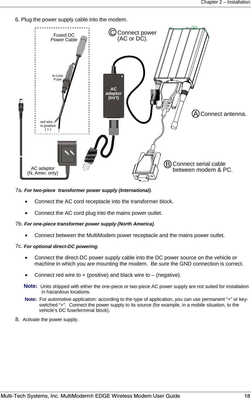
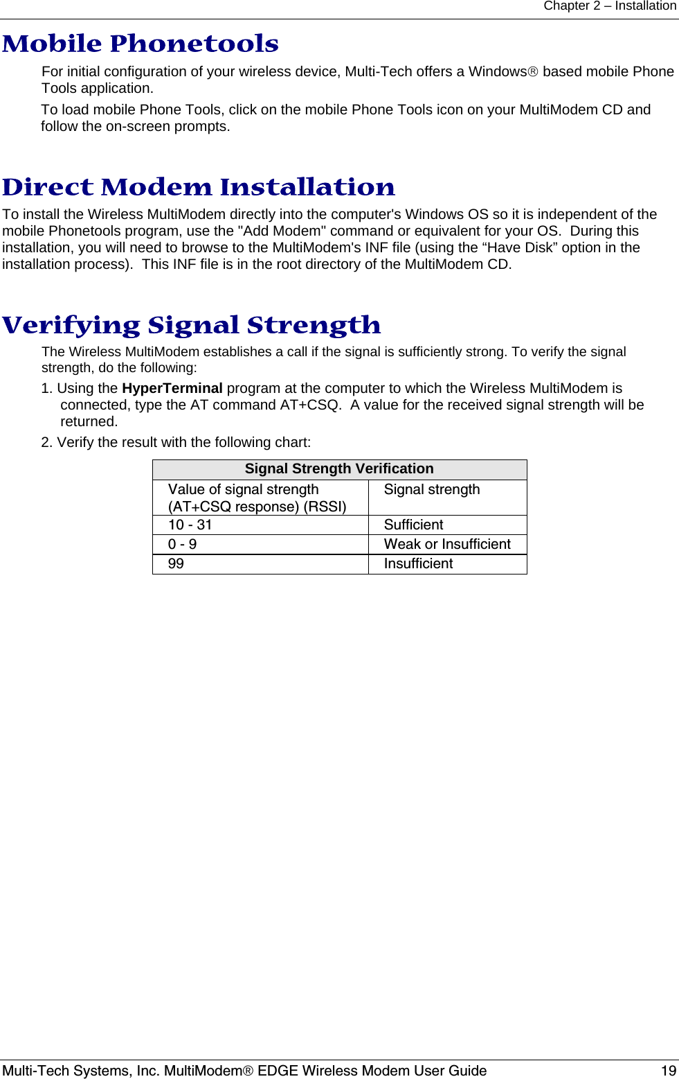
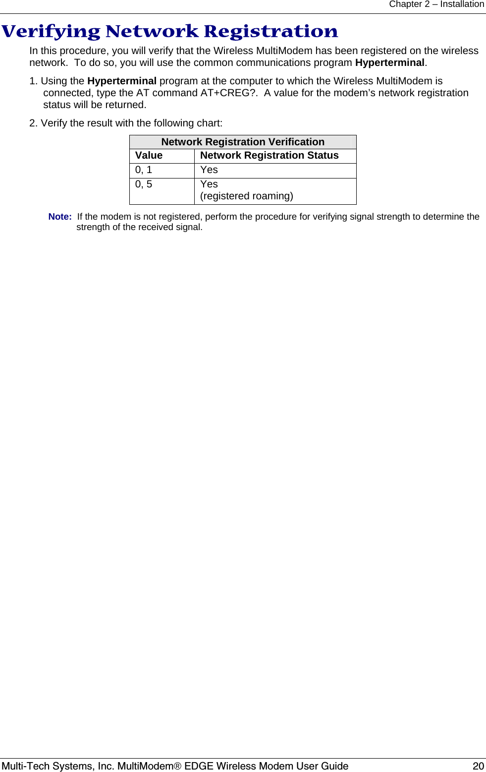
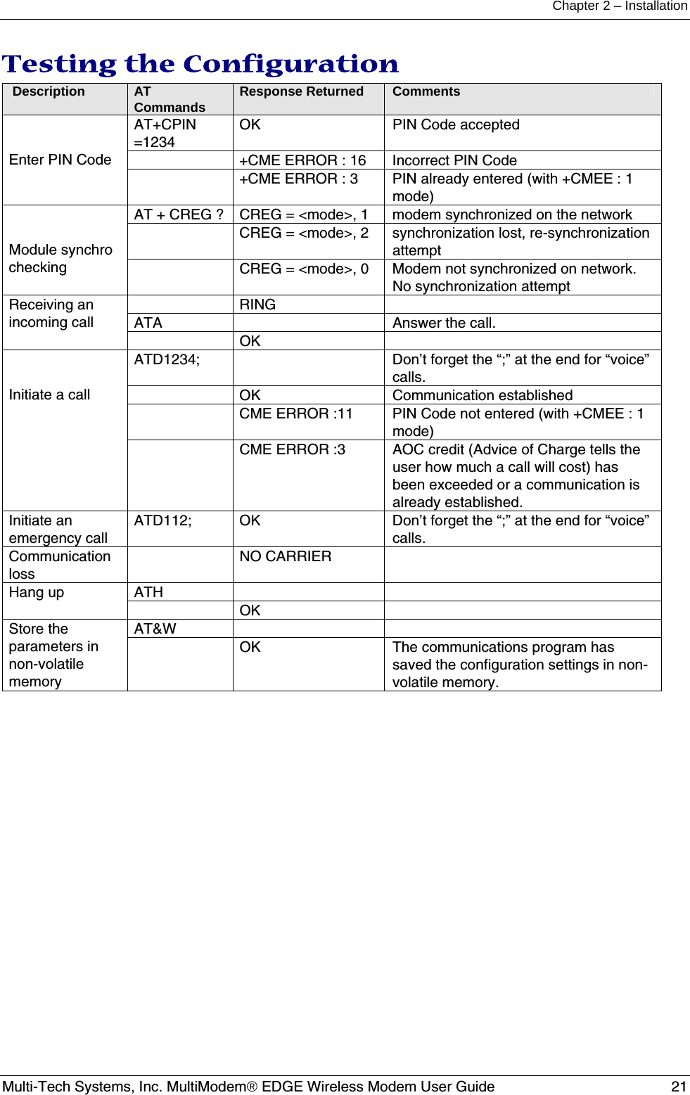
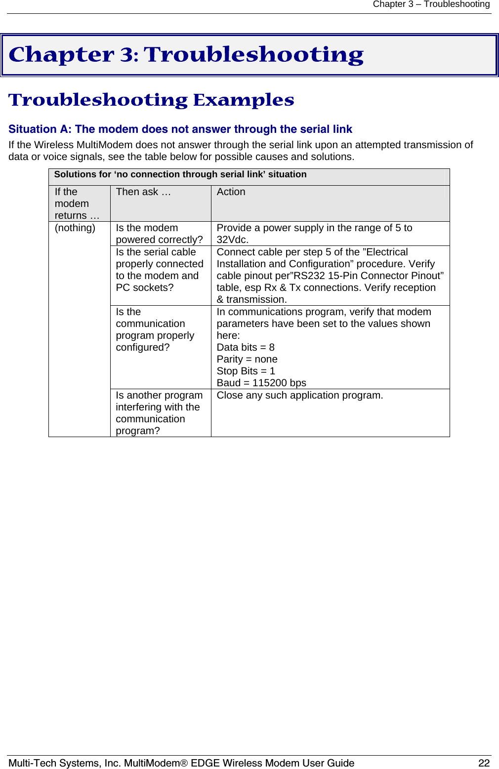
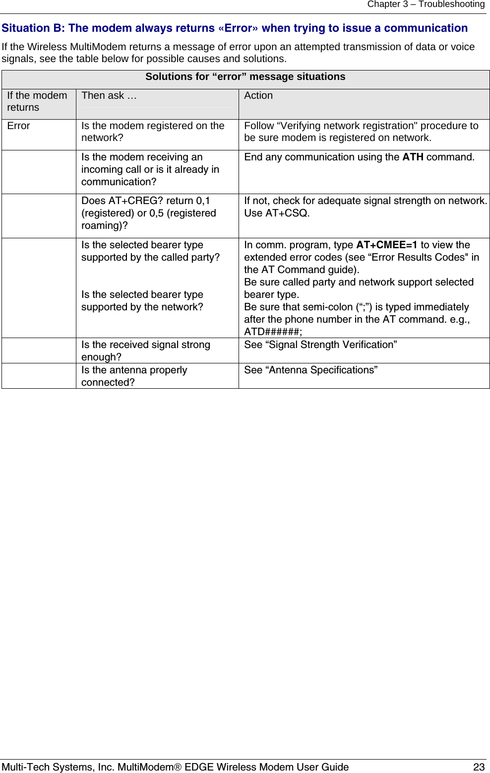
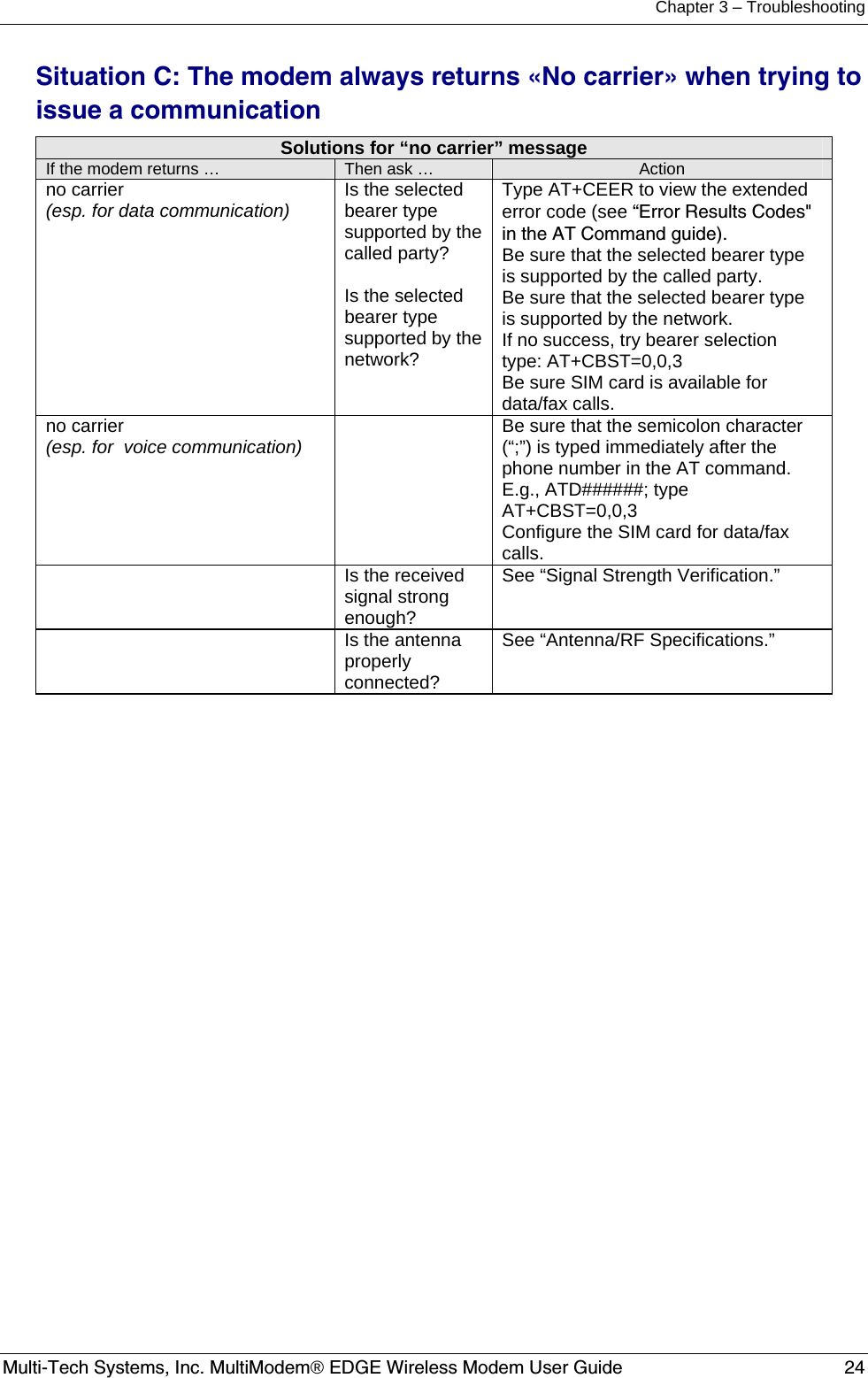
User Guide MTCBA E