Multi Tech Systems 92U07A31817 GSM/GPRS Modem Module User Manual
Multi Tech Systems Inc GSM/GPRS Modem Module
UserManual.wiki
>
Multi Tech Systems
>
92U07A31817 User Manual
User Manual
Navigation menu
Upload a User Manual
Namespaces
Wiki Guide
HTML
PDF
Info
Views
User Manual
Discussion / Help
Navigation
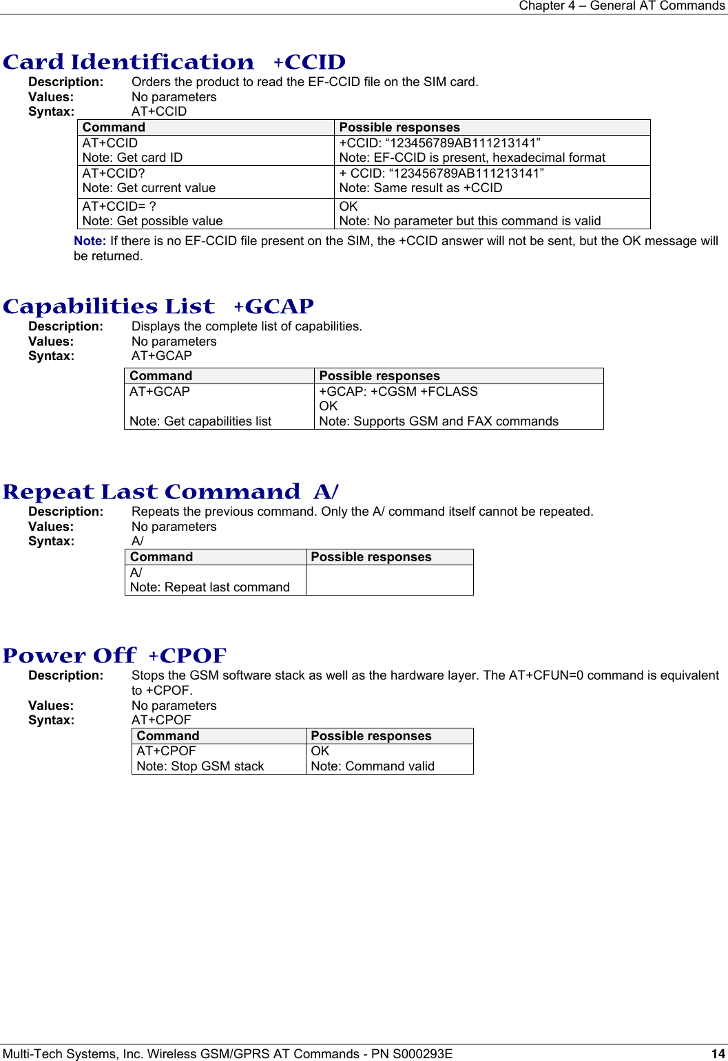
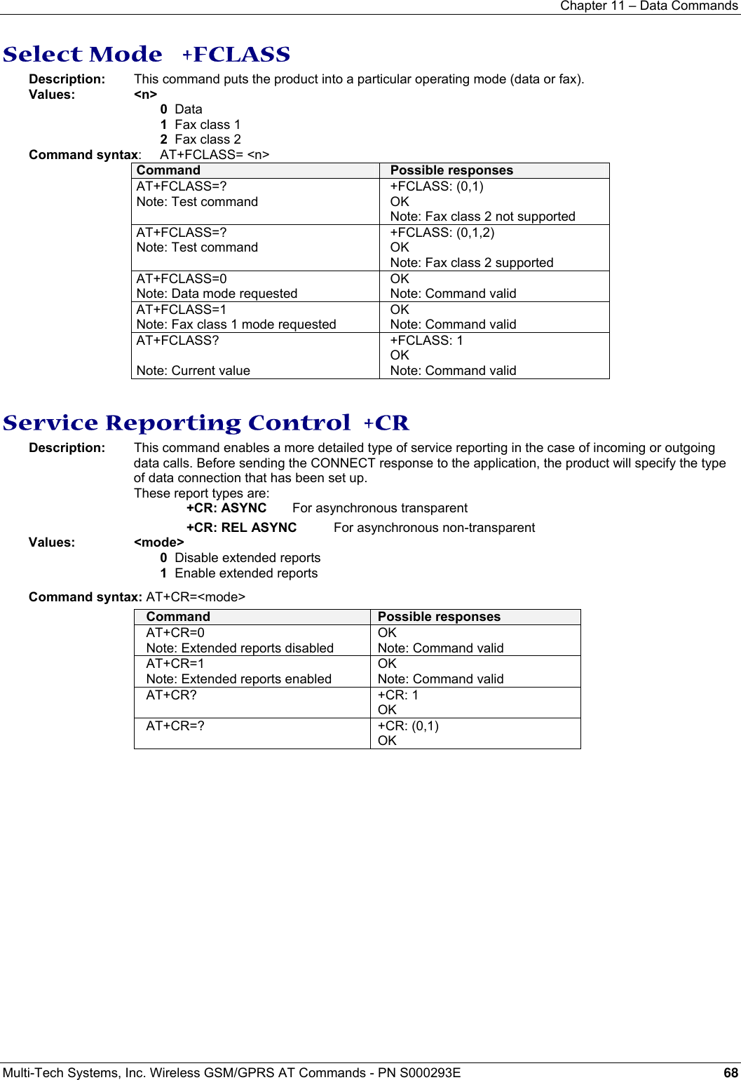
![Chapter 1 – Introduction Multi-Tech Systems, Inc. Wireless GSM/GPRS AT Commands - PN S000293E 9 Chapter 1 – Introduction Scope of This Document This document describes the AT-command based messages exchanged between an application and the Multi-Tech Systems, Inc. products in order to manage GSM-related events or services. Related Documents This interface specification is based on the following recommendations: [1] ETSI GSM 07.05: Digital cellular telecommunications system (Phase 2); Use of DTE-DCE interface for Short Message Service (SMS) and Cell Broadcast Service (CBS) [2] ETSI GSM 07.07: Digital cellular telecommunications system (Phase 2); AT command set for GSM Mobile Equipment (ME) [3] ITU-T Recommendation V.25 ter: Serial asynchronous automatic dialing and control [4] ETSI GSM 03.40: Digital cellular telecommunications system (Phase 2); Technical implementation of the Short Message Service (SMS) Point-to-Point (PP) [5] ETSI GSM 03.38: Digital cellular telecommunications system (Phase 2); Alphabets and language-specific information [6] ETSI GSM 04.80: Digital cellular telecommunications system (Phase 2): Mobile radio interface layer 3, Supplementary service specification, Formats and coding Definitions The words, “Mobile Station” (MS) or “Mobile Equipment” (ME) are used for mobile terminals supporting GSM services. A call from a GSM mobile station to the PSTN is called a “mobile originated call” (MOC) or “outgoing call”, and a call from a fixed network to a GSM mobile station is called a “mobile terminated call” (MTC) or “incoming call”. In this document, the word “product” refers to any Multi-Tech product supporting the AT commands interface.](https://usermanual.wiki/Multi-Tech-Systems/92U07A31817/User-Guide-789840-Page-9.png)
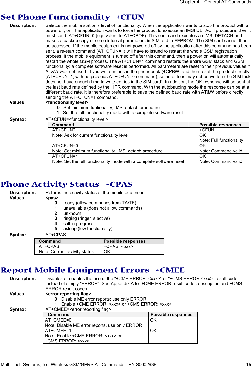
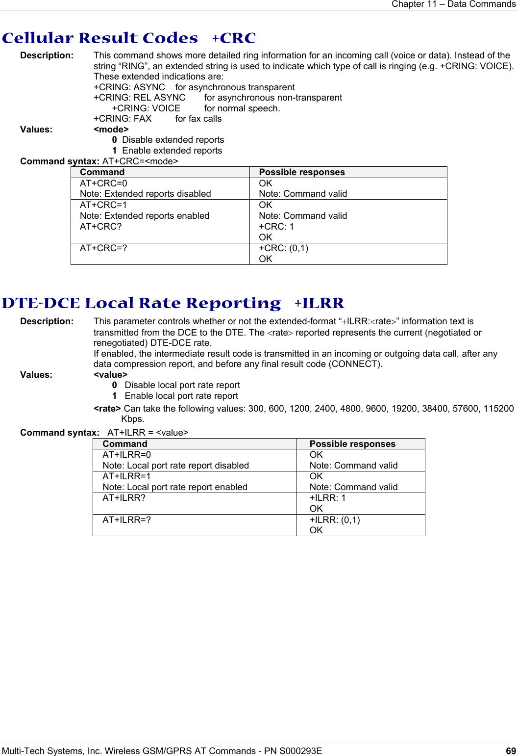
![Chapter 5 – AT Call Control Commands Multi-Tech Systems, Inc. Wireless GSM/GPRS AT Commands - PN S000293E 17 Chapter 5 – AT Call Control Commands Dial Command D Description: The ATD command sets a voice, data or fax call. As per GSM 02.30, the dial command also controls supplementary services. For a data or a fax call, the application sends the following ASCII string to the product (the bearer must be previously selected with the +CBST command): ATD<nb> where <nb> is the destination phone number; For a voice call, the application sends the following ASCII string to the product: (the bearer may be selected previously, if not a default bearer is used). ATD<nb>; where <nb> is the destination phone number. Please note that for an international number, the local international prefix does not need to be set (usually 00) but does need to be replaced by the ‘+’ character. Example: to set up a voice call to Multi-Tech offices from another country, the AT command is: “ATD+17637853600;” Note that some countries/regions may have specific numbering rules for their GSM handset numbering. Values: <nb> Destination phone number <I> Optional parameter <I> means “invocation” (restrict CLI presentation) <i> Means “suppresssion” (allow CLI presentation) <mem> Phonebook (one of SM, LD, MC, ME, RC, MT or SN). A default value can be selected by +CPBS command. <index> Call number at indicated offset from the phonebook selected by the +CPBS command. <name> Call number corresponding to given name from the phonebook selected by the +CPBS command. The response to the ATD command is one of the following: Verbose result code Numeric code (with ATV0 set) Description OK 0 if the call succeeds, for voice call only CONNECT <speed> 10,11,12,13,14,15 if the call succeeds, for data calls only, <speed> takes the value negotiated by the product. BUSY 7 If the called party is already in communication NO ANSWER 8 If no hang up is detected after a fixed network time-out NO CARRIER 3 Call setup failed or remote user release. Use the AT+CEER command to know the failure cause Direct Dialing from a Phonebook (stored in the SIM card) can be performed with the following commands: ATD> <index>; to call <index> from the selected phonebook (by the +CPBS command) ATD> “BILL”; to call “BILL” from the selected phonebook ATD> mem <index> (mem is SM, LD, MC, ME, RC, MT or SN, see +CPBS command) allows direct dialing from a phonebook number. Does not function with ON mem. Syntax: ATD<nb>[<I>][;] ATD>[<mem>]<index>[<I>][;] ATD>[<mem>]<name>[<I>][;] Command Possible responses AT+CPBS? Note: Which phonebook is selected ? +CPBS:”SM”,8,10 Note: ADN phonebook is selected, 8 locations are used and 10 locations are available ATD>SM6; Note: Call index 6 from AND phonebook OK Note: Call succeeds](https://usermanual.wiki/Multi-Tech-Systems/92U07A31817/User-Guide-789840-Page-17.png)
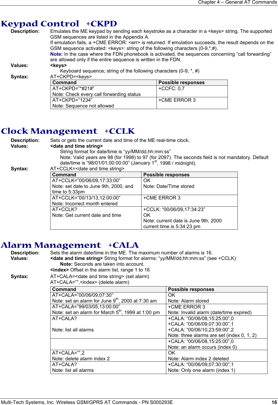
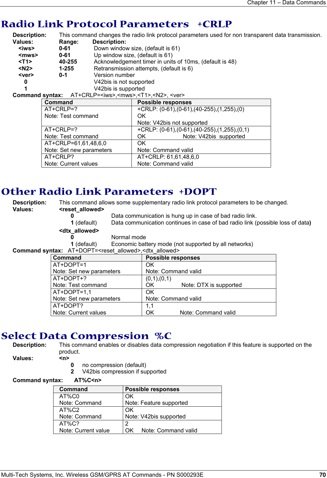
![Chapter 5 – AT Call Control Commands Multi-Tech Systems, Inc. Wireless GSM/GPRS AT Commands - PN S000293E 20 Automatic Dialing with DTR %D Description: This command enables and disables: Automatic dialing of the phone number stored in the first location of the ADN phonebook, Automatic sending of the short message (SMS) stored in the first location of the SIM. The number is dialed when DTR OFF switches ON. The short message is sent when DTR OFF switches ON. Values: <n> Enable or disables automatic message transmission or number dialing. Informs the product that the number is a voice rather than a fax or data number. 0 Disables automatic DTR number dialing / message transmission. 1; Enables automatic DTR dialing if DTR switches from OFF to ON; Dials the phone number in the first location of the ADN phonebook. Voice call. 1 Activates automatic DTR dialing if DTR switches from OFF to ON; Dials the phone number in the first location of the ADN phonebook. Data or Fax call. 2 Activates automatic DTR message transmission if DTR switches from OFF to ON. Syntax: AT%D<n>[;] Command Possible responses AT%D1; Note: Activates DTR number dialing OK Note: Command has been executed DTR is OFF DTR switches ON Note: The number in the first location of the ADN is dialed automatically DTR switches OFF Note: The product goes on-hook AT%D2 Note: Activates DTR short message sending OK Note: Command has been executed Automatic Answer S0 Description: This S0 parameter determines and controls the product automatic answering mode. Values: <value> is the number of rings before automatic answer (3 characters padded with zeros) Range of values is 0 to 255. Syntax: ATS0=<value> Command Possible responses ATS0=2 Note: Automatic answer after 2 rings OK ATS0? Note: Current value 002 OK Note: always 3 characters padded with zeros ATS0=0 Note: No automatic answer OK Note: Command valid All others S-parameters (S6,S7,S8 …) are not implemented. Incoming Call Bearer +CICB Description: This command sets the type of incoming calls when no incoming bearer is given (see +CSNS). Note: Setting the +CICB command affects the current value of +CSNS. Values: <mode> 0 Data 1 Fax 2 Speech Syntax: AT+CICB=<mode> Command Possible responses AT+CICB=1 Note: If no incoming bearer, force a fax call OK Note: Command accepted AT+CICB=2 Note: If no incoming bearer, force a voice call OK Note: Command accepted AT+CICB? Note: Interrogate value +CICB: 2 OK Note: Default incoming bearer: voice call AT+CICB=? Note: Test command +CICB: (0-2) OK Note: Speech, data or fax default incoming bearer](https://usermanual.wiki/Multi-Tech-Systems/92U07A31817/User-Guide-789840-Page-20.png)

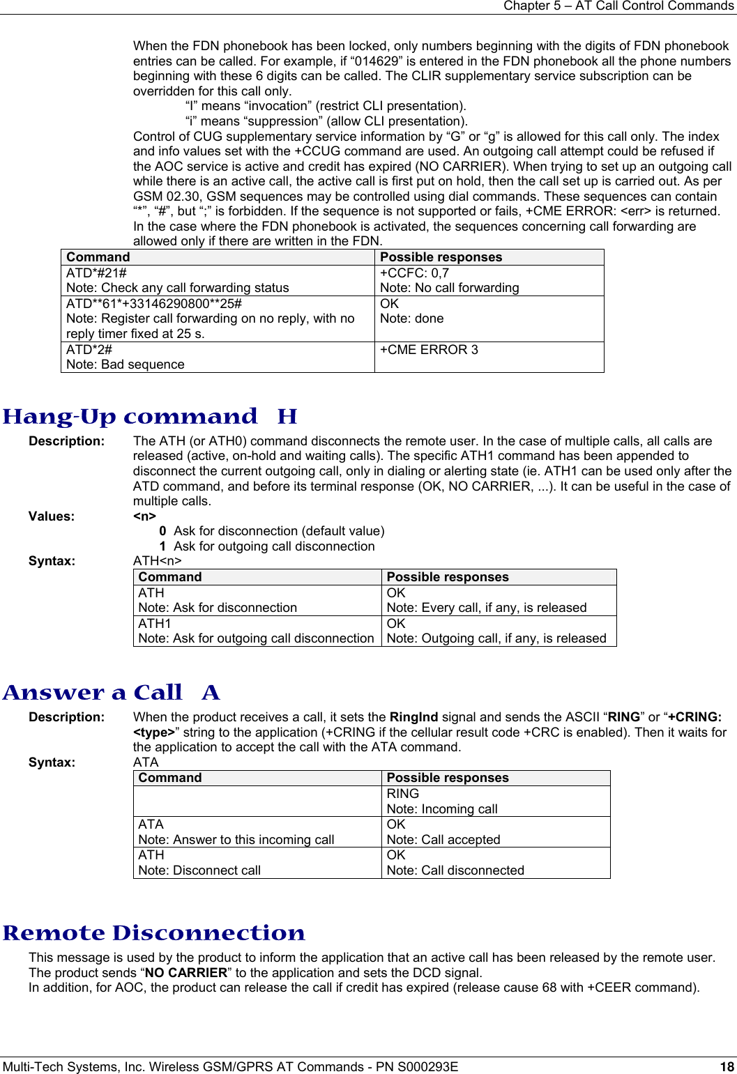
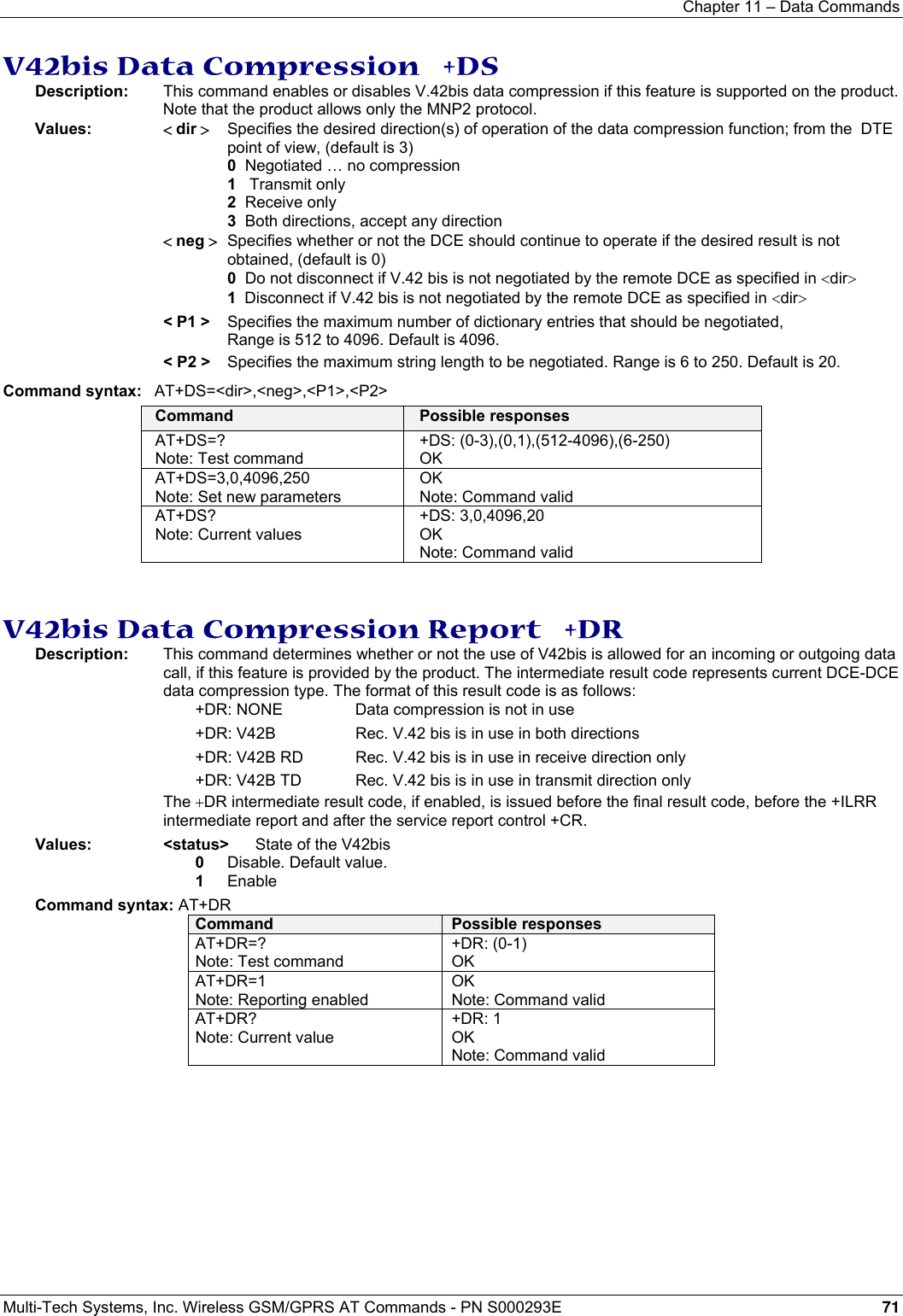
![Chapter 5 – AT Call Control Commands Multi-Tech Systems, Inc. Wireless GSM/GPRS AT Commands - PN S000293E 23 Echo Cancellation +ECHO Description: This command enables, disables or configures the Echo Cancellation functions for voice calls (in rooms, in cars, etc.). It is necessary to tune the Microphone gain (AT+VGT) and the Speaker gain (AT+VGR) before activating the Echo Cancellation. Values: <mode> 0 Deactivate Echo 1 Activate Echo When mode = 1 is choosen, AlgoId is mandatory. <AlgoId> 1 Echo cancellation 1 3 Echo cancellation 3 To use Echo cancellation 3, the ECHO feature must be activated. Echo cancellation 1 (4 parameters): <Volout> The parameter <Volout> specifies the maximum attenuation of the switch 0 31 db (default) 1 29 db 2 27 db 3 25 db … 14 3 db 15 1 db <Step> The parameter <Step> specifies the attenuation step between attenuation and no attenuation. 0 1 db 1 2 db 2 3 db <PcmThRel> specifies the relative threshold between max and min energy information. The allowed range is [0 - 31]. Default = 10. <PcmThMax> specifies threshold of max energy information. The allowed range is [0 - 31]. Default = 7. Echo Cancellation 3 (3 parameters): <AlgoParam> high value leads to high echo attenuation but the full-duplex quality will be less efficient. The allowed range is [ 0 ; 63 ]. (30 by default) <NoiseThres> indicates the noise threshold. Low value leads to high noise attenuation. The threshold 32767 indicates no noise attenuation. The allowed range is [0 ;32767]. The default is 8000. <NmbTaps> indicates the Number of Taps of the Adaptive Filter. The allowed range is [64 -256]. The default is 256. 64 taps = short Echo 256 taps = long Echo. Read Command: AT+ECHO? This command returns the current settings of the Echo cancellation. Returns: +ECHO: <Status>,<AlgoId>, <Param1>,<Param2>, <Param3>, <Param4>, <Param5>,<Param6> The number of parameters displayed depends on the algorythm used. For Echo cancellation 1, 4 parameters are displayed, 3 parameters are displayed for Echo cancellation 3. <Status> 0 Echo Deactivated. 1 Echo Activated for Mic/Spk one. 2 Echo Activated for Mic/Spk two. 3 Reset the product. Note: You can activate/deactivate the echo cancellation during a call without resetting the product if the <AlgoId> parameter is not changed, but you have to use the syntax with all parameters: AT+ECHO=1,3,30,8000,256 for instance.](https://usermanual.wiki/Multi-Tech-Systems/92U07A31817/User-Guide-789840-Page-23.png)
![Chapter 5 – AT Call Control Commands Multi-Tech Systems, Inc. Wireless GSM/GPRS AT Commands - PN S000293E 24 Syntax: AT+ECHO= <mode> [,<AlgoId>, <Param1>,<Param2>,<Param3>,<Param4>,<Param5>,<Param6>] Command Possible responses AT+CMEE=1 Note: Enables the use of result code OK AT+SPEAKER? + SPEAKER: 0 OK Note: Speaker ONE and Micro ONE are activeAT+SIDET=0 Note: Deactivate the Sidetone OK AT+SIDET? +SIDET: 0,0 AT+ECHO? Note: Read current settings +ECHO: 0,1,0,3,10,7 OK AT+ECHO=1,1,0,3,10,7 Note: Active Echo cancellation 1 for Mic/Spk one.OK AT+ECHO? Note: Read current settings +ECHO: 1,1,0,3,10,7 OK AT+ECHO=1,3,30,8000,256 Note: Activate the Echo cancellation 3 +CME ERROR: 519 Note: The new algorithm will be activated after a reset of the product AT+ECHO? Note: Read the Echo cancellation settings +ECHO: 3,3,30,8000,256 OK AT+CFUN=1 Note: Reset the product OK AT+ECHO? Note: Read current settings +ECHO: 1,3,30,8000,256 OK AT+ECHO=0 Note: Deactivate the Echo Cancellation OK SideTone Modification +SIDET Description: This command sets the level of audio feedback in the speaker (microphone feedback in the speaker). Values: <val1> 0 SideTone is disabled 1 SideTone is enabled <val2> (default value 0 will be used if this parameter is not given) 0 0 db 1 - 6 db 2 - 12 db 3 - 18 db Syntax: AT+SIDET=<val1>,<val2> Command Possible responses AT+SIDET=1,0 OK Note: Command valid AT+SIDET? Note: Current value +SIDET: 1,0 OK Note: Command valid](https://usermanual.wiki/Multi-Tech-Systems/92U07A31817/User-Guide-789840-Page-24.png)
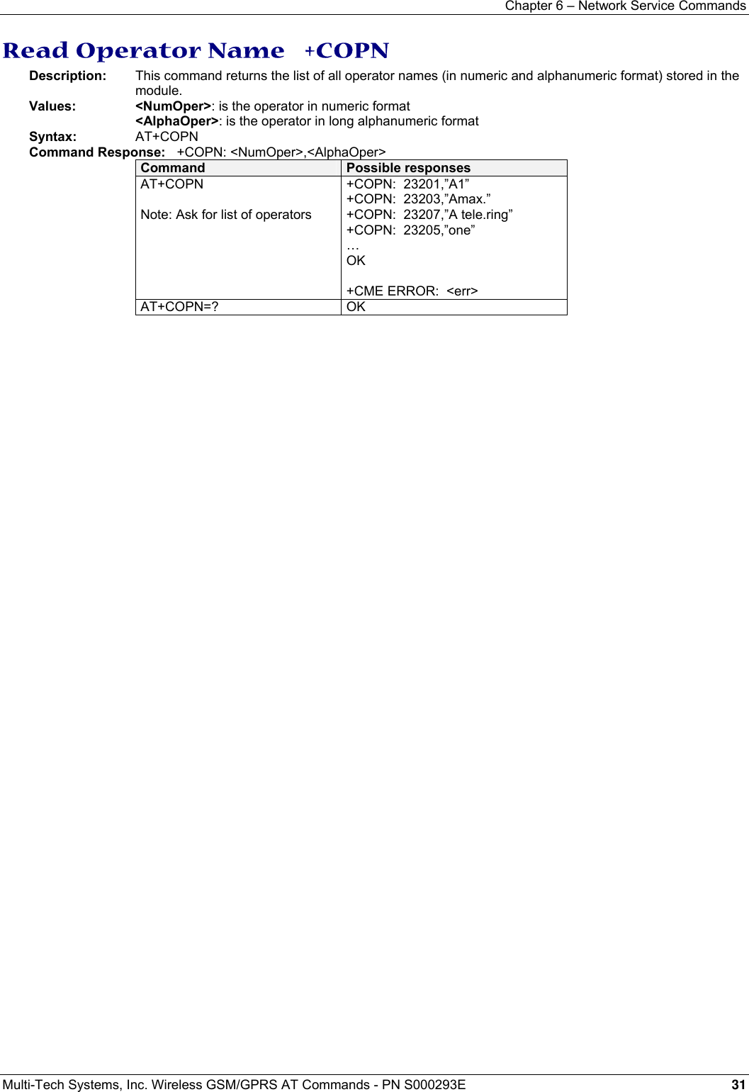
![Chapter 6 – Network Service Commands Multi-Tech Systems, Inc. Wireless GSM/GPRS AT Commands - PN S000293E 26 Chapter 6 – Network Service Commands Signal Quality +CSQ Description: This command determines the received signal strength indication (<rssi>) and the channel bit error rate (<ber>) with or without a SIM card inserted. Values: <rssi>: 0 -113 dBm or less 1 -111 dBm 2 to 30 -109 to –53 dBm 31 -51dBm or greater 99 not known or not detectable <ber>: 0…7: as RXQUAL values in the table GSM 05.08 99 not known or not detectable Syntax: AT+CSQ Command Possible responses AT+CSQ +CSQ: <rssi>,<ber> (Note: <rssi> and <ber> as defined below) OK Operator Selection +COPS Description: There are three possible ways of selecting an operator (PLMN): 1) The product is in manual mode. It then tries to find the operator specified by the application and if found, tries to register. 2) The product is in automatic mode. It then tries to find the home operator and if found, tries to register. If not found, the product automatically searches for another network. 3) The product enters into manual/automatic mode, and then tries to find an operator as specified by the application (as in manual mode). If this attempt fails, it enters automatic mode. If this is successful, the operator specified by the application is selected. The mobile equipment then enters into automatic mode. Note: The read command returns the current mode and the currently selected operator. In manual mode, this PLMN may not be the one set by the application (as it is in the search phase). These commands are not allowed during one communication. Values: <mode> 0 automatic (default value) 1 manual 2 deregistration ; ME will be unregistered until <mode>=0 or 1 is selected. 3 set only <format> (for read command AT+COPS?) 4 manual / automatic (<oper> shall be present), if manual selection fails, automatic mode is entered. <format> <format>: format of <oper> field 0 long alphanumeric format <oper> 1 short alphanumeric format <oper> 2 numeric <oper> (default value) <stat>: status of <oper> <stat> 0 unknown 1 available 2 current 3 forbidden <oper>: operator identifier (MCC/MNC in numeric format only for operator selection) The long alphanumeric format can be up to 16 characters long (see Appendix A for operator names description, field is “Name”). The short alphanumeric format can be up to 8 characters long. Syntax: AT+COPS=<mode>, [<format> [ , <oper> ] ] (To force an attempt to select and register on a network, the application must send this command)](https://usermanual.wiki/Multi-Tech-Systems/92U07A31817/User-Guide-789840-Page-26.png)
![Chapter 6 – Network Service Commands Multi-Tech Systems, Inc. Wireless GSM/GPRS AT Commands - PN S000293E 27 Possible responses for AT+COPS=<mode>: OK (Network is selected with full service) +CME ERROR: 30 (No network service), +CME ERROR: 32 (Network not allowed – emergency calls only) +CME ERROR: 3 (not allowed during one Communication) +CME ERROR: 4 (Incorrect parameters) +CME ERROR: 527 (Please wait, and retry your selection later) +CME ERROR: 528 (Location update failure – emergency calls only) +CME ERROR: 529 (Selection failure – emergency calls only) Response syntax for AT+COPS?: +COPS: <mode> [, <format>, <oper> ] Response syntax for AT+COPS=?: +COPS: [list of supported (<stat>, long alphanumeric <oper>, short alphanumeric <oper>s, numeric <oper>) s] If an incoming call occurs during a PLMN list request, the operation is aborted (+CME ERROR: 520) and the unsolicited RING appears. Command Possible responses AT+COPS? Note: Ask for current PLMN +COPS: 0,2,20801 OK Note: Home PLMN is France Telecom Orange AT+COPS=? Note: Ask for PLMN list +COPS: (2,”F Itinéris”,”Itline”,”20801”), (3,”F SFR”,”SFR”,”20810”) OK Note: Home PLMN is France Telecom SFR network has been detected AT+COPS=1,2,20810 Note: Ask for registration on SFR network +CME ERROR: 32 Note: Network not allowed – emergency calls only AT+COPS=1,1,23433 Note: Ask for registration on UK Orange network +CME ERROR: 529 Note: Selection failed – emergency calls only AT+COPS=0 Note: Ask for registration on home network OK Note: Succeeded AT+COPS=3,0 Note: Set <format> to long alphanumeric OK AT+COPS? Note: Ask for current PLMN +COPS: 0,0,”Orange F” OK Note: Home PLMN is France Telecom Orange AT+COPS=2 Note: Ask for deregistration from network OK Note: Succeeded AT+COPS? Note: Ask for current PLMN +COPS: 2 Note: ME is unregistered until <mode>=0 or 1 is selected](https://usermanual.wiki/Multi-Tech-Systems/92U07A31817/User-Guide-789840-Page-27.png)
![Chapter 6 – Network Service Commands Multi-Tech Systems, Inc. Wireless GSM/GPRS AT Commands - PN S000293E 28 Network Registration +CREG Description: This command is used by the application to ascertain the registration status of the product. Values: <mode> 0 Disable network registration unsolicited result code (default) 1 Enable network registration code result code +CREG: <stat> 2 Enable network registration and location information unsolicited result code +CREG: <stat>,<lac>,<ci> if there is a change of network cell. <stat> 0 not registered, ME is not currently searching for a new operator. 1 registered, home network. 2 not registered, ME currently searching for a new operator to register to. 3 registration denied. 4 unknown. 5 registered, roaming. <lac>: string type; two byte location area code in hexadecimal format (e.g. “00C3” equals 195 in decimal). <ci>: string type; two byte cell ID in hexadecimal format. Syntax: Command Syntax: AT+CREG= <mode> Response syntax: +CREG: <mode>, <stat> [ ,<lac>,<ci> ] for AT+CREG? Command only Command Possible responses AT+CREG? +CREG: <mode>,<stat> OK Note: As defined here-above AT+CREG=0 Note: Disable network registration unsolicited result codeOK Note: Command valid AT+CREG=1 Note: Enable network registration unsolicited result code OK Note: Command valid AT+CREG=2 Note: Enable network registration and location information unsolicited result code OK Note: Command valid AT+CREG=? +CREG: (0-2) Note: 0,1,2 <mode> values are supported Read Operator Name +WOPN Description: This command returns the operator name in alphanumeric format when given the numeric format. With E-ONS feature, lac is an optional parameter to read names from OPL/PNN sim files. If it is not entered, name will be given with current lac. Note that in limited service, current lac is set to 0. Values: <format> is the required format. Only long (0) and short (1) alphanumeric formats are supported. <NumOper> is the operator in numeric format. <AlphaOper> is the operator in long or short alphanumeric format (see Appendix A for description). <lac> is the two byte Location Area Code to be used to get the PLMN name. If it is not entered, Current lac will be used (0 if limited service). Syntax: Command syntax: AT+WOPN=<format>,<NumOper> Response syntax: +WOPN: <format>,<AlphaOper> Command Possible responses AT+WOPN=? Note: Test command OK AT+WOPN=0,20801 Note: Give an operator in numeric format +WOPN: 0,”Orange F” OK Note: Alphanumeric answer AT+WOPN=0,99999 Note: Give a wrong operator +CME ERROR: 22 Note: Not found AT+WOPN=0,2081,36 Note: Give an operator in numeric format for lac 36 +WOPN: 0, “OrangeF” OK Note: Alphanumeric answer](https://usermanual.wiki/Multi-Tech-Systems/92U07A31817/User-Guide-789840-Page-28.png)
![Chapter 6 – Network Service Commands Multi-Tech Systems, Inc. Wireless GSM/GPRS AT Commands - PN S000293E 29 Selection of Preferred PLMN List +CPLS Description: This command selects one PLMN selector with access technology list in the SIM card that is used by AT+CPOL command. Values: <List>: 0 User controlled PLMN selector with access technology EF_PLMNwAct Note: if this file is not found EF_PLMNSel will be selected 1 Operator controlled PLMN selector with access technology EF_OPLMNwAct 2 Home PLMN selector with access technology EF_HPLMNwAct Syntax: AT+CPLS= <List> Command Possible responses AT+CPLS? Note: Ask for selection of the SIM file +CPLS: 1 OK Note: EF_OPLMNwAct is selected AT+CPLS=0 Note: selection of EF_PLMNwAct Note: if EF_PLMNwAct is not present, EF_PLMNsel will be selected AT+CPLS=1 Note: selection of EF_OPLMNwAct +CME ERROR: 3 Note: EF_OPLMNwAct is not present AT+CPLS=? Note: Get possible values +CPLS: (0-2) OK Note: The 3 files with Acces technology are present and can be selected AT+CPLS=? Note: Get possible values +CPLS: (0) OK Note: Only EF_PLMNwAct or EF_PLMNsel can be selected Preferred Operator List +CPOL Description: This command edits (or updates) the SIM preferred list of networks. This list is read in the SIM file selected by the command AT+CPLS. Values: <index>: position of the operator record in the Sim preferred operator list. Use AT+CPOL=? to view the maximum index of the selected EF. <format> 0 long alphanumeric format for <oper> 1 short alphanumeric format for <oper> 2 numeric format for <oper> <oper>: characterstring or integer (see <format>) indicating operator identifier. <GSM_AcT>: GSM access technology <GSMcomp_Act>: GSM compact access technology <Utran_Act>: UTRA access technology 0 access technology not selected 1 access technology selected Syntax: AT+CPOL= [<index>] [,<format>[,<oper>[,<GSM_AcT>,<GSMcomp_Act>,<Utran_Act>]]] The different possibilities are: AT+CPOL = <index> to delete an entry. AT+CPOL = , <format> to set the format used by the read command (AT+CPOL?). AT+CPOL = , <format>, <oper> to put <oper> in the next free location. AT+CPOL = <index> , <format> , <oper> to write <oper> in the <format> at the <index>. AT+CPOL = <index>,<format>,<oper>,<GSM_AcT>,<GSMcp_Act>,<Utran_Act> To write <oper> in the <format> at the <index> precising the access technology (in the case of EF_PLMNwact, EF_HPLMNwact or EF_OPLMNwact is present). Note: Per default if Acces technology parameters are not given, the GSM access technology will be chosen. The supported format are those of the +COPS command. The length of this list is limited to 85 entries for EF_PLMNsel, and 51 for EF_PLMNwAct, EF_OPLMNwAct, EF_HPLMNwAct. (See table on next page)](https://usermanual.wiki/Multi-Tech-Systems/92U07A31817/User-Guide-789840-Page-29.png)
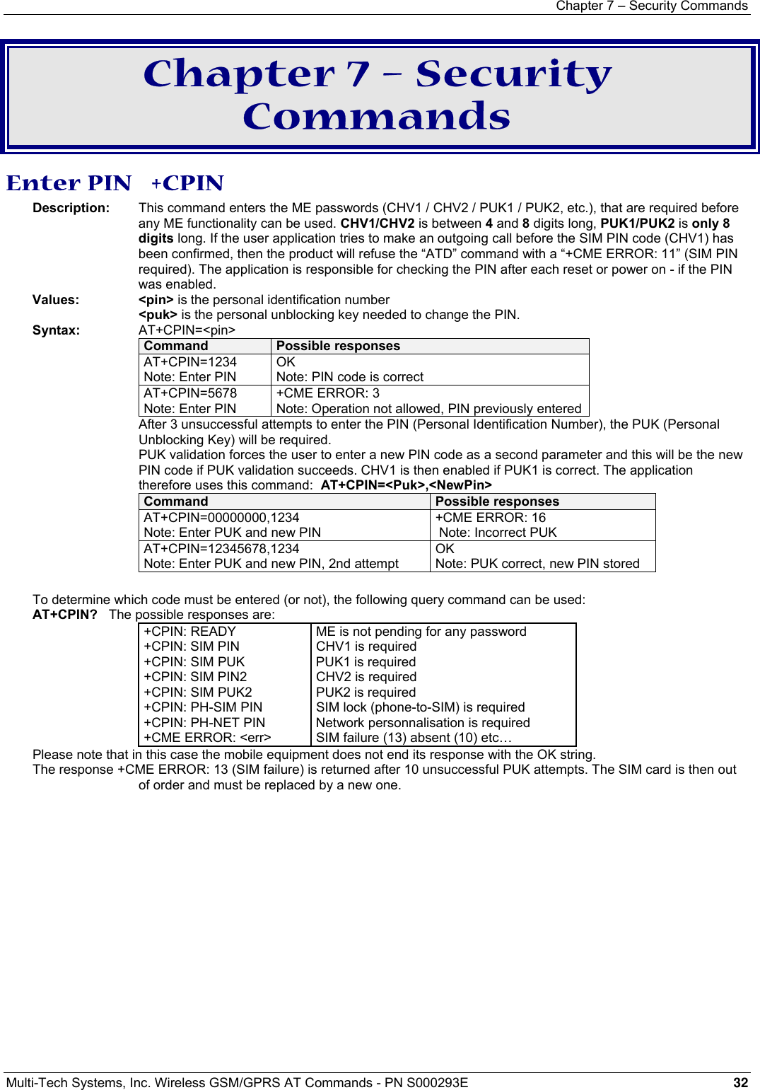
![Chapter 7 – Security Commands Multi-Tech Systems, Inc. Wireless GSM/GPRS AT Commands - PN S000293E 35 Facility Lock +CLCK Description: This command locks, unlocks or interrogates an ME or network facility <fac>. Note: Test SIM cards (with MCC=001 & MNC=01) do not check “PS”, “PN”, “PU”, “PP” and “PC” locks. Values: <fac> supported facilities: “PS”: SIM lock facility with an 8-digit password. “SC“: PIN enabled (<mode> = 1) / disabled (<mode> = 0) “AO”: BAOC (Barr All Outgoing Calls) “OI”: BOIC (Barr Outgoing International Calls) “OX”: BOIC-exHC (Barr Outgoing. International Calls except to Home Country) “AI”: BAIC (Barr All Incoming Calls) “IR”: BIC-Roam (Barr Inc. When Roaming outside Home Country) “AB”: All Barring services “AG”: All outGoing barring services “AC”: All inComing barring services “PN”: Network lock with an 8-digit password (NCK). “PU”: Network Subset lock with an 8-digit password (NSCK). “PP”: Service Provider lock with an 8-digit password (SPCK). “PC”: Corporate lock with an 8-digit password (CCK). “FD”: SIM Fixed Dialing Numbers (FDN) memory feature (PIN2 is required as <password>) <mode> 0 unlock the facility 1 lock the facility 2 query status <class> A facility status can be changed for only one class, or for all classes (7 or omitted). 1 Voice (telephony) 2 Data (apply to all bearer services) 4 Fax (facsimile services) 8 Short Message service 7 Equal to all classes (Default value) Any attempt to combine different classes will result in activation / deactivation / interrogation of all classes. Password maximum length is given with the AT+CPWD=? Command. Note: It will not possible to lock the FDN phonebook if this one is not loaded. Command syntax: AT+CLCK= <fac>,<mode>[,<passwd>[,<class>] ] Response syntax: +CLCK: <status> [ ,<class1> ]<CR><LF>+CLCK: <status>,<class2> [ … ] ] Command Possible responses AT+CLCK=”SC”,1,1234 Note: Enable PIN OK Note: PIN was correct AT+CLCK? Note: Read PIN status +CLCK:(“PS”,0),(“SC”,0),(“FD”,0),(“PN“,0),(“PU“,0),(“PP“,0),(“PC“,0) OK Note: PIN is enabled, no SIM lock, no network lock, no information on Call barring (no longer supported in GSM Technical Specification 07.07) AT+CLCK=”SC”,0,5555 Note: Disable PIN +CME ERROR: 16 Note: PIN was wrong AT+CPIN=1234 Note: Enter PIN OK Note: PIN was good AT+CLCK=? Note: Request supported facilities +CLCK: (“PS”,”SC”,”AO”,”OI”,”OX”,”AI”,”IR”,”AB”,”AC”, ”FD”,"PN","PU","PP",”PN”) OK Note: Supported facilities AT+CLCK=”PN”,1,12345678 Note: Activate network lock OK Network lock activated AR+CLCK=”AO”,1,1234,2 Note: Activate all outgoing calls except data calls OK Note: Call barring is activate AT+CLCK=”AO”,2 Note: Query BAOC status +CLCK: 1,2 OK Note: BAOC activate for data calls only AT+CLCK=”SC”,0,0000 Note: Disable PIN +CME ERROR: 521 Note: PIN deactivation is forbidden with this SIM card](https://usermanual.wiki/Multi-Tech-Systems/92U07A31817/User-Guide-789840-Page-35.png)
![Chapter 8 – Phonebook Commands Multi-Tech Systems, Inc. Wireless GSM/GPRS AT Commands - PN S000293E 39 Write Phonebook Entry +CPBW Description: This command writes a phonebook entry in location number <index> in the current phonebook memory storage. “RC” and “MC” phonebooks could be erased only by +CPBW. Adding a field and/or modifying a field is not allowed for these phonebooks. This command is not allowed for “EN”, “LD”, “MC”, “RC”, “MT”, and “SN” phonebooks (they cannot be written). Note: +CSCS (Select Character set) does not affect the format for phonebook entries. Values: <index> Integer type value depending on the capacity of the phonebook memory. <number> Phone number in ASCII format. <type> TON/NPI (Type of address byte in integer format). Note: for the <type> parameter, all values are allowed from 0 to 255, but the MSB will be set to 1 in all cases (ex: a <type> value of 17 will be written as 145). <text> String type. Note: For the <text> parameter all strings starting with “80” , “81” or “81” are considered in UCS2 format. See the Appendix G (Coding of Alpha fields in the SIM for UCS2). Syntax: AT+CPBW=<index>[,<number>[,<type>[,<text>]]] Command Possible responses AT+CPBW=? Note: Test command +CPBW: (1-50),60,(129,145),10 OK Note: 50 locations, phone number = 60 digits max, TON/NPI of 129 or 145, text length = 10 AT+CPBW= 3 Note: Erase location 3 OK Note: Location 3 erased AT+CPBW=5,”112”,129,”SOS” Note: Write at location 5 OK Note: Location 5 written AT+CPBW=5,”01290917”,129,”Jacky” Note: Overwrite location 5 OK Note: Location 5 overwritten AT+CPBW=6,”01292349”,129,”8000410042” Note: write location 6 (UCS2 format for the <text> field) OK Note: Location 6 is written AT+CPBW=,”+33145221100”,145,”SOS” Note: Write at the first location available OK Note: First location available is written AT+CPBW=,”0345221100”,129,”SOS” Note: Write at the first location available +CME ERROR: 20 Note: Phonebook full AT+CPBW=57,”112”,129,”WM” Note: Write at location 57 (wrong) +CME ERROR: 21 Note: Invalid index AT+CPBW=7,”012345678901234567890”,129,”WAVE” Note: Write at location 7 a phone number exceeding the limit (21 digits) +CME ERROR: 26 Note: Phone number too long AT+CPBW=7,”0122334455”,129,”TEL” Note: Write at location 7 along text (11 characters) +CME ERROR: 24 Note: Text too long AT+CPBW=8,”01292349”,129,”80xyz” Note: write location OK Note: Location 8 is written. The string has a wrong UCS2 format, it is therefore considered as an ASCII string When the fixed dialing phonebook (FDN) is locked, this command is not allowed. Moreover, when the FDN is unlocked, PIN2 is required to write in the FDN phonebook. But if PIN2 authentication has been performed during the current session, the +CPBW command with FDN is allowed. Command Possible responses AT+CPBS=”FD” Note: Choose FDN OK AT+CPBW=5,”01290917”,129,”Jacky” Note: Write in FDN at location 5 +CME ERROR: 17 Note: SIM PIN2 is required AT+CPIN? SIM PIN2 Note: SIM PIN2 is required AT+CPIN=5678 Note: Enter SIM PIN2 OK AT+CPBW=5,”01290917”,129,”Jacky” Note: Write in FDN at location 5 OK Note: Writing in FDN is now allowed](https://usermanual.wiki/Multi-Tech-Systems/92U07A31817/User-Guide-789840-Page-39.png)
![Chapter 8 – Phonebook Commands Multi-Tech Systems, Inc. Wireless GSM/GPRS AT Commands - PN S000293E 42 Avoid Phonebook Initialization +WAIP Description: This specific command allows the initialization of all phonebooks to be inhibited during subsequent boots. Values: <mode> 0 Normal initialization (with phonebooks) 1 No phonebook initialization Syntax: AT+WAIP=<mode> Command Possible responses AT+WAIP? Note: Current values ? +WAIP:0 OK Note: Default value (init phonebooks) AT+WAIP=? Note: Possible values ? +WAIP: (0,1) OK Note: Disable / enable AT+WAIP =1 Note: Inhibit initialization of phonebooks (next boot) OK Note: no answer AT&W Note: Save modifications in EEPROM Caution: The given value should be stored in EEPROM. Therefore, the AT&W command must be used to save the new <mode> value. Note: phonebook commands are allowed if +WAIP=1 (after boot). If a phonebook command is entered, a “+CME ERROR: 3” is returned. Delete Calls Phonebook +WDCP Description: This specific command deletes the calls listed in some phonebooks. Values: <calls phonebook> “LD” SIM (ME extended) Last dialing phonebook “MC” ME missed calls list phonebook “RC” ME received calls list phonebook Syntax: +WDCP=<calls phonebook> Command Possible responses AT+WDCP? OK AT+WDCP=? Note: Possible values ? +WDCP: ("LD","MC","RC") OK Note: Identifiers of the phonebooks supporting a list of callsAT+WDCP=”LD” Note: Delete all the content of Last Dialing phonebook.OK Note: Last Dialing phonebook is now empty. Set Voice Mail Number +CSVM Description: This commands sets/gets and enables/disables the voice mail number in memory.. Values: <mode> 0 Disable the voice mail number 1 Enable the voice mail number <number> Phone number in ASCII format. <type> TON/NPI (Type of address byte in integer format). Note: For the <type> parameter, all values are allowed from 0 to 255, but the MSB will be set to 1 in all cases (ex: a <type> value of 17 will be written as 145). Syntax: AT+CSVM=<mode>[,<number>[,<type>]] Command Possible responses AT+CSVM? Note: Get mail number +CSVM: 1,”660”,129 OK Note: Voice mail number “660” is activated AT+CSVM=? Note: Possible values ? +CSVM: (0-1),(129,145) OK Note: activation/deactivation and format 129 & 145 are supported AT+CSVM=0,”888”,129 Note: Disable Voice Mail number and change value to “888”. OK](https://usermanual.wiki/Multi-Tech-Systems/92U07A31817/User-Guide-789840-Page-42.png)
![Chapter 9 – Short Messages Commands Multi-Tech Systems, Inc. Wireless GSM/GPRS AT Commands - PN S000293E 43 Chapter 9 – Short Messages Parameters Definition <da> Destination Address, coded according to the GSM Technical Specification 03.40 TP-DA <dcs> Data Coding Scheme, coded according to document [5] <dt> Discharge Time in string format: “yy/MM/dd,hh:mm:ss±zz”(Year [00-99], Month [01-12], Day [01-31], Hour, Minute, Second and Time Zone [quarters of an hour] ) <fo> First Byte, coded according to SMS-SUBMIT first byte in document [4], default value is 17 for SMS-SUBMIT <index> Place of storage in memory <length> Text mode (+CMGF=1): number of characters PDU mode (+CMGF=0): length of the TP data unit in bytes <mem1> Memory used to list, read and delete messages (+CMGL, +CMGR and +CMGD) <mem2> Memory used to write and send messages (+CMGW, +CMSS) <mid> CBM Message Identifier <mr> Message Reference <oa> Originator Address <pid> Protocol Identifier <pdu> For SMS: GSM 04.11 SC address followed by GSM Technical Specification 03.40 TPDU in hexadecimal format, coded as specified in doc [4] For CBS: GSM Technical Specification 03.41 TPDU in hexadecimal format <ra> Recipient Address <sca> Service Center Address <scts> Service Center Time Stamp in string format: “yy/MM/dd,hh:mm:ss±zz” (Year/Month/Day,Hour:Min:Seconds±TimeZone) <sn> CBM Serial Number <st> Status of a SMS-STATUS-REPORT <stat> Status of message in memory <tooa> Type-of-Address of <oa> <tora> Type-of-Address of <ra> <tosca> Type-of-Address of <sca> <total1> Number of message locations in <mem1> <total2> Number of messages locations in <mem2> <used1> Total number of messages locations in <mem1> <used2> Total number of messages locations in <mem2> <vp> Validity Period of the short message, default value is 167](https://usermanual.wiki/Multi-Tech-Systems/92U07A31817/User-Guide-789840-Page-43.png)
![Chapter 9 – Short Messages Commands Multi-Tech Systems, Inc. Wireless GSM/GPRS AT Commands - PN S000293E 44 Select Message Service +CSMS Description: The supported services include originated (SMS-MO) and terminated short messages (SMS-MT) as well as Cell Broadcast Message (SMS-CB) services. Values: <service> 0 SMS AT commands are compatible with GSM 07.05 Phase 2 version 4.7.0. 1 SMS AT commands are compatible with GSM 07.05 Phase 2 + version . Syntax: AT+CSMS=<service> Command Possible responses AT+CSMS=0 Note: SMS AT command Phase 2 version 4.7.0 +CSMS: 1,1,1 OK Note: SMS-MO, SMS-MT and SMS-CB supported AT+CSMS=1 Note: SMS AT command Phase 2 + +CSMS: 1,1,1 Note: SMS-MO, SMS-MT and SMS-CB supported AT+CSMS? Note: Current values ? +CSMS: 0,1,1,1 OK Note: GSM 03.40 and 03.41 (SMS AT command Phase 2 version 4.7.0 AT+CSMS=? Note: Possible services +CSMS: (0,1) OK New Message Acknowledgement +CNMA Description: This command allows reception of a new message routed directly to the TE to be acknowledged., In TEXT mode, only positive acknowledgement to the network (RP-ACK) is possible. In PDU mode, either positive (RP-ACK) or negative (RP-ERROR) acknowledgement to the network is possible. Acknowledgement with +CNMA is possible only if the +CSMS parameter is set to 1 (+CSMS=1) when a +CMT or +CDS indication is shown (see +CNMI command). If no acknowledgement occurs within the network timeout, an RP-ERROR is sent to the network. The <mt> and <ds> parameters of the +CNMI command are then reset to zero (do not show new message indication). Values: <n>: Type of acknowledgement in PDU mode 0 send RP-ACK without PDU (same as TEXT mode) 1 send RP-ACK with optional PDU message 2 send RP-ERROR with optional PDU message <length>: Length of the PDU message Syntax: Command syntax in text mode: AT+CNMA Command syntax in PDU mode: AT+CNMA [ = <n> [ , <length> [ <CR> Note: PDU is entered using <ackpdu> format instead of <pdu> format (e.g., SMSC address field is not present). PDU is entered <ctrl-Z / ESC> ] ] ] Example of new message acknowledgement in TEXT mode Command Possible responses AT+CMGF=1 Note: Set TEXT mode OK Note: TEXT mode valid AT+CNMI=2,2,0,0,0 Note: <mt>=2 OK +CMT: “123456”,”98/10/01,12:30 00+00”,129,4 ,32,240, “15379”,129,5<CR><LF> Received message Note: message received AT+CNMA Note: acknowledge the message received OK Note: send positive acknowledgement to the network AT+CNMA Note: try to acknowledge again +CMS ERROR: 340 Note: no +CNMA acknowledgment expected](https://usermanual.wiki/Multi-Tech-Systems/92U07A31817/User-Guide-789840-Page-44.png)
![Chapter 9 – Short Messages Commands Multi-Tech Systems, Inc. Wireless GSM/GPRS AT Commands - PN S000293E 45 Example of new message acknowledgement in PDU mode: Command Possible responses AT+CMGF=0 Note: Set PDU mode OK Note: PDU mode valid +CMT: ,29 07913366003000F1240B913366920547F30000003003419404800B506215D42ECFE7E17319 Note: message received AT+CNMA=2,<length> <CR> … Pdu message … <Ctrl-Z/ESC> Note: negative acknowledgement for the message. OK Note: send a negative acknowledgement to the network (RP-ERROR) with PDU message (<ackpdu> format). Preferred Message Storage +CPMS Description: This command allows the message storage area to be selected (for reading, writing, etc). Values: <mem1>: Memory used to list, read and delete messages. It can be: “SM” SMS message storage in SIM (default) “BM” CBM message storage (in volatile memory). “SR” Status Report message storage (in SIM if the EF-SMR file exists, otherwise in the ME non volatile memory) Note: “SR” ME non-volatile memory is cleared when another SIM card is inserted. It is kept, even after a reset, while the same SIM card is used. <mem2>: Memory used to write and send messages “SM” SMS message storage in SIM (default). If the command is correct, the following message indication is sent: +CPMS: <used1>,<total1>,<used2>,<total2> When <mem1> is selected, all following +CMGL, +CMGR and +CMGD commands are related to the type of SMS stored in this memory. Syntax: AT+CPMS=<mem1>,[<mem2>] Command Possible responses AT+CPMS=? Note: Possible message storages +CPMS: ((“SM”,”BM”,”SR”),(“SM”)) OK Note: Read, list, delete: SMS, CBM or SMS Status Report Write, send: SMS AT+CPMS? Note: Read +CPMS: “SM”,3, 10,”SM”,3,10 OK Note: Read, write…SMS from/to SIM 3 SMS are stored in SIM. 10 is the total memory available in SIM AT+CPMS=”AM” Note: Select false message storage+CMS ERROR: 302 AT+CPMS=”BM” Note: Select CBM message storage+CPMS: 2,20,3,10 OK Note: Read, list, delete CBM from RAM 2 CBM are stored in RAMAT+CPMS? Note: Read +CPMS: “BM”,2,20,”SM”,3,10 OK Note: Read list, delete CBM from RAM, Write SMS to SIM](https://usermanual.wiki/Multi-Tech-Systems/92U07A31817/User-Guide-789840-Page-45.png)
![Chapter 9 – Short Messages Commands Multi-Tech Systems, Inc. Wireless GSM/GPRS AT Commands - PN S000293E 48 New Message Indication +CNMI Description: This command selects the procedure for message reception from the network. Values: <mode>: controls the processing of unsolicited result codes Note: Only <mode>=2 is supported. Any other value for <mode> (0,1 or 3) is accepted (return code will be OK), but the processing of unsolicited result codes will be the same as with <mode>=2. 0 Buffer unsolicited result codes in the TA. If TA result code buffer is full, indications can be buffered in some other place, or the oldest indications may be discarded and replaced with the new received indications 1 Discard indication and reject new received message unsolicited result codes when TA-TE link is reserved. Otherwise forward them directly to the TE 2 Buffer unsolicited result codes in the TA when TA-TE link is reserved and flush them to the TE after reservation. Otherwise forward them directly to the TE 3 Forward unsolicited result codes directly to the TE. TA-TE link specific inband used to embed result codes and data when TA is in on-line data mode <mt>: sets the result code indication routing for SMS-DELIVERs. Default is 0. 0 No SMS-DELIVER indications are routed. 1 SMS-DELIVERs are routed using unsolicited code: +CMTI: “SM”,<index> 2 SMS-DELIVERs (except class 2 messages) are routed using unsolicited code: +CMT: [<alpha>,] <length> <CR> <LF> <pdu> (PDU mode) or +CMT: <oa>,[<alpha>,] <scts> [,<tooa>, <fo>, <pid>, <dcs>, <sca>, <tosca>, <length>] <CR><LF><data> (text mode) 3 Class 3 SMS-DELIVERs are routed directly using code in <mt>=2 ; Message of other classes result in indication <mt>=1 <bm>: Set the rules for storing received CBMs (Cell Broadcast Message) types depend on its coding scheme, the setting of Select CBM Types (+CSCB command) and <bm>. Default is 0. 0 No CBM indications are routed to the TE. The CBMs are stored. 1 The CBM is stored and an indication of the memory location is routed to the customer application using unsolicited result code: +CBMI: “BM”, <index> 2 New CBMs are routed directly to the TE using unsolicited result code. +CBM: <length><CR><LF><pdu> (PDU mode) or +CBM:<sn>,<mid>,<dcs>,<page>,<pages>(Text mode) <CR><LF> <data> 3 Class 3 CBMs: as <bm>=2. Other classes CBMs: as <bm>=1. <ds> for SMS-STATUS-REPORTs. Default is 0. 0 No SMS-STATUS-REPORTs are routed. 1 SMS-STATUS-REPORTs are routed using unsolicited code: +CDS: <length> <CR> <LF> <pdu> (PDU mode) or +CDS: <fo>,<mr>, [<ra>] , [<tora>], <scts>,<dt>,<st> (Text mode) 2 SMS-STATUS-REPORTs are stored and routed using the unsolicited result code: +CDSI: “SR”,<index> <bfr> Default is 0. 0 TA buffer of unsolicited result codes defined within this command is flushed to the TE when <mode> 1…3 is entered (OK response shall be given before flushing the codes) 1 TA buffer of unsolicited result codes defined within this command is cleared when <mode> 1…3 is entered. Syntax: AT+CNMI=<mode>,<mt>,<bm>,<ds>,<bfr> Command Possible responses AT+CNMI=2,1,0,0,0 Note: <mt>=1 OK AT+CMTI: “SM”,1 Note: message received AT+CNMI=2,2,0,0,0 Note: <mt>=2 OK +CMT: “123456”,”98/10/01,12:30 00+00”,129,4,32,240, “15379”,129,5<CR><LF> Note: message received AT+CNMI=2,0,0,1,0 Note: <ds>=1 OK AT+CMGS=”+33146290800”<CR> Message to send <ctrl-Z> Note: Send a message in text mode +CMGS: 7 OK Note: Successful transmission +CDS: 2, 116, ”+33146290800”, 145, “98/10/01,12:30:07+04”, “98/10/01 12:30:08+04”, 0 Note: message was correctly delivered](https://usermanual.wiki/Multi-Tech-Systems/92U07A31817/User-Guide-789840-Page-48.png)
![Chapter 9 – Short Messages Commands Multi-Tech Systems, Inc. Wireless GSM/GPRS AT Commands - PN S000293E 49 Read Message +CMGR Description: This command allows the application to read stored messages. The messages are read from the memory selected by the +CPMS command. Command syntax: AT+CMGR=<index> Response syntax for text mode: +CMGR: <stat>,<oa>,[<alpha>,] <scts> [,<tooa>,<fo>,<pid>,<dcs>,<sca>,<tosca>,<length>] <CR><LF> <data> (for SMS-DELIVER only) +CMGR: <stat>,<da>,[<alpha>,] [,<toda>,<fo>,<pid>,<dcs>, [<vp>], <sca>, <tosca>,<length>]<CR><LF> <data> (for SMS-SUBMIT only) +CMGR: <stat>,<fo>,<mr>,[<ra>],[<tora>],<scts>,<dt>,<st> (for SMS-STATUS-REPORT only) Response syntax for PDU mode: +CMGR: <stat>, [<alpha>] ,<length> <CR><LF> <pdu> A message read with status “REC UNREAD” will be updated in memory with the status “REC READ”. Note: The <stat> parameter for SMS Status Reports is always “READ”. Command Possible responses AT+CMTI: “SM”,1 Note: New message received AT+CMGR=1 Note: Read the message +CMGR: “REC UNREAD”,”0146290800”, ”98/10/01,18:22:11+00”,<CR><LF> ABCdefGHI OK AT+CMGR=1 Note: Read the message again +CMGR: “REC UNREAD”,”0146290800”, ”98/10/01,18:22:11+00”,<CR><LF> ABCdefGHI OK Note: Message is read now AT+CMGR=2 Note: Read at a wrong index +CMS ERROR: 321 Note: Error: invalid index AT+CMGF=0 ;+CMGR=1 Note: In PDU mode +CMGR: 2,,<length> <CR><LF><pdu> OK Note: Message is stored but unsent, no <alpha>field AT+CMGF=1;+CPMS=”SR”;+CNMI=,,,2 Reset to text mode, set read memory to “SR”, and allow storage of further SMS Status Report into “SR” memory OK AT+CMSS=3 Send an SMS previously stored +CMSS: 160 OK +CDSI: “SR”,1 New SMS Status Report stored in “SR” memory at index 1 AT+CMGR=1 Read the SMS Status Report +CMGR: "READ",6,160, "+33612345678",129,"01/05/31,15:15:09+00", "01/05/31,15:15:09+00",0 OK](https://usermanual.wiki/Multi-Tech-Systems/92U07A31817/User-Guide-789840-Page-49.png)
![Chapter 9 – Short Messages Commands Multi-Tech Systems, Inc. Wireless GSM/GPRS AT Commands - PN S000293E 50 List Message +CMGL Description: This command allows the application to read stored messages, by indicating the type of the message to read. The messages are read from the memory selected by the +CPMS command. Values: <stat> possible values (status of messages in memory): Text mode possible values PDU mode possible values Status of messages in memory “REC UNREAD” 0 received unread messages “REC READ” 1 received read messages “STO UNSENT” 2 stored unsent messages “STO SENT” 3 stored sent messages “ALL” 4 all messages Note: For SMS Status Reports, only “ALL” / 4 and “READ” / 1 values of the <stat> parameter will list messages ; other values will only return OK. Command syntax: AT+CMGL=<stat> Response syntax for text mode: +CMGL: <index>,<stat>,<da/oa>[,<alpha>], [<scts>, <tooa/toda>, <length>] <CR><LF><data> (for SMS-DELIVER and SMS-SUBMIT, may be followed by other <CR><LF>+CMGL:<index>…) +CMGL: <index>,<stat>,<fo>,<mr>,[<ra>],[<tora>],<scts>,<dt>,<st> (for SMS-STATUS-REPORT only, may be followed by other <CR><LF>+CMGL:<index>…) Response syntax for PDU mode: +CMGL: <index>,<stat>, [<alpha>], <length> <CR><LF> <pdu> (for SMS-DELIVER, SMS-SUBMIT and SMS-STATUS-REPORT, may be followed by other <CR><LF>+CMGL:<index>…) Command Possible responses AT+CMGL=“REC UNREAD” Note: List unread messages in text mode +CMGL: 1,”REC UNREAD”,”0146290800”, <CR><LF> Unread message ! +CMGL: 3,”REC UNREAD”, “46290800”, <CR><LF> Another message unread! OK Note: 2 messages are unread, these messages will then have their status changed to “REC READ” (+CSDH:0) AT+CMGL=”REC READ” Note: List read messages in text mode +CMGL: 2,”REC READ”,”0146290800”, <CR><LF> Keep cool OK AT+CMGL=”STO SENT” Note: List stored and sent messages in text mode OK Note: No message found AT+CMGL=1 Note: List read messages in PDU mode +CMGL: 1,1,,26 <CR><LF> 07913366003000F3040B913366920547F40013001190412530400741AA8E5A9C5201 OK](https://usermanual.wiki/Multi-Tech-Systems/92U07A31817/User-Guide-789840-Page-50.png)
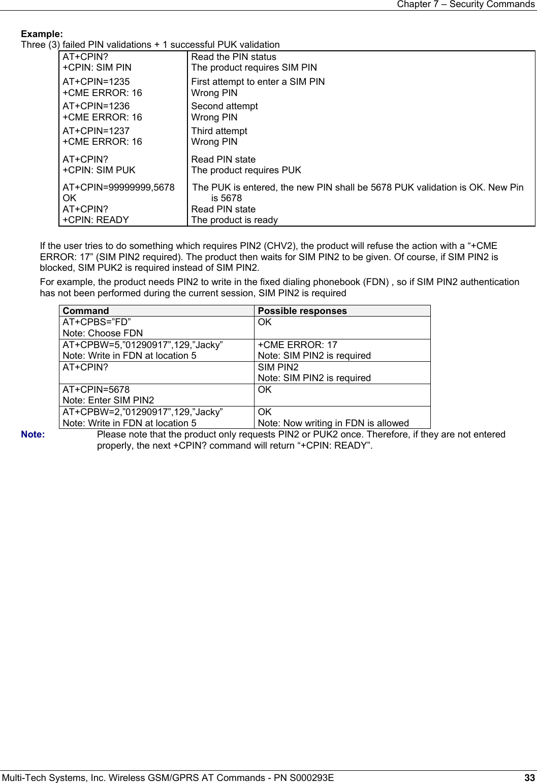
![Chapter 9 – Short Messages Commands Multi-Tech Systems, Inc. Wireless GSM/GPRS AT Commands - PN S000293E 51 Send Message +CMGS Description: The <address> field is the address of the terminal to which the message is sent. To send the message, simply type, <ctrl-Z> character (ASCII 26). The text can contain all existing characters except <ctrl-Z> and <ESC> (ASCII 27). This command can be aborted using the <ESC> character when entering text. In PDU mode, only hexadecimal characters are used (‘0’…’9’,’A’…’F’). Values: <ctrl-Z / ESC > Note: Type this to send the message Command syntax in text mode: AT+CMGS= <da> [ ,<toda> ] <CR> Text is entered: <ctrl-Z / ESC > Command syntax in PDU mode: AT+CMGS= <length> <CR> PDU is entered: <ctrl-Z / ESC > Command Possible responses AT+CMGS=”+33146290800”<CR> Please call me soon, Fred. <ctrl-Z> Note: Send a message in text mode +CMGS: <mr> OK Note: Successful transmission AT+CMGS=<length><CR><pdu><ctrl-Z> Note: Send a message in PDU mode +CMGS: <mr> OK Note: Successful transmission The message reference <mr> is returned to the application and allocated by the product. This number begins with 0, is incremented by one for each outgoing message (successes and failures), and is cyclic on one byte (0 follows 255). Note: This number is not a storage number. Outgoing messages are not stored. Write Message to Memory +CMGW Description: This command stores a message in memory (either SMS-SUBMIT or SMS-DELIVERs). The memory location <index> is returned (no choice possible as with phonebooks +CPBW). Text or PDU is entered as described for the Send Message +CMGS command. Values: <oa/da> Originating or Destination Address Value in string format <tooa/toda> Type of Originating / Destination Address <stat> Integer type in PDU mode (default 2 for +CMGW) or string type in text mode (default “STO UNSENT” for +CMGW). Indicates the status of message in memory. If <stat> is omitted, the stored message is considered as a message to send 0 “REC UNREAD” 1 “REC READ” 2 “STO UNSENT” 3 “STO SENT” <length>: Length of the actual data unit in bytes Command syntax in text mode: (<index> is returned in both cases) AT+CMGW= <oa/da> [,<tooa/toda> [,<stat> ] ] <CR> Enter text : <ctrl-Z / ESC> Command syntax in PDU mode: AT+CMGW= <length> [,<stat>] <CR> Give PDU: <ctrl-Z / ESC> Response syntax: +CMGW: <index> or +CMS ERROR: <err> if writing fails Command Possible responses AT+CMGW=”+33146290800”<CR> Hello how are you ?<ctrl-Z> Note: Write a message in text mode +CMGW: 4 OK Note: Message stored in index 4 AT+CMGW=<length><CR><pdu><ctrl-Z> Note: Write a message in PDU mode +CMGW: <index> OK Note: Message stored in <index>](https://usermanual.wiki/Multi-Tech-Systems/92U07A31817/User-Guide-789840-Page-51.png)
![Chapter 9 – Short Messages Commands Multi-Tech Systems, Inc. Wireless GSM/GPRS AT Commands - PN S000293E 52 Send Message from Storage +CMSS Description: This command sends a message stored at location value <index>. Values: <index> location of stored message <da> desination address <toda> type of destination address <mr> message reference Command syntax: AT+CMSS=<index>[,<da> [,<toda>] ] Response syntax: +CMSS: <mr> or +CMS ERROR: <err> if sending fails If a new recipient address <da> is given, it will be used instead of the one stored with the message Command Possible responses AT+CMGW=0660123456<CR> Today is my birthday +CMGW: 5 OK Note: Message stored with index 5 AT+CMSS=5, 0680654321 Note: Send the message 5 to a different destination number AT+CMSS:<mr> OK Note: Successful transmission AT+CMSS=5, 0680654321 Note: Send the message 5 to a different destination number +CMSS:<mr> OK Note: Successful transmission Set Text Mode Parameters +CSMP Description: This command selects a value for <vp>, <pid>, and <dcs>. Values: <fo> byte comprises 6 different fields: B7 B6 B5 b4 b3 b2 b1 b0 RP UDHI SRR VPF RD MTI RP Reply Path, not used in text mode. UDHI User Data Header Information, b6=1 if the beginning of the User Data field contains a Header in addition to the short message. This option is not supported in +CSMP command, but can be used in PDU mode (+CMGS). SRR Status Report Request, b5=1 if a status report is requested. This mode is supported. VPF Validity Period Format b4=0 & b3=0 -> <vp> field is not present b4=1 & b3=0 -> <vp> field is present in relative format Others formats (absolute & enhanced) are not supported. RD Reject Duplicates, b2=1 to instruct the SC to reject an SMS-SUBMIT for an SM still held in the SC that has the same <mr> and <da> as the previously submitted SM from the same <oa>. MTI Message Type Indicator b1=0 & b0=0 -> SMS-DELIVER (in the direction SC to MS) b1=0 & b0=1 -> SMS-SUBMIT (in the direction MS to SC) In text mode <vp> is only coded in “relative” format. The default value is 167 (24 hours). This means that one byte can describe different values: VP value Validity period value 0 to 143 (VP + 1) x 5 minutes (up to 12 hours) 144 to 167 12 hours + ( (VP – 143) x 30 minutes ) 168 to 196 (VP – 166) x 1 day 197 to 255 (VP – 192) x 1 week <pid> is used to indicate the higher layer protocol being used or indicates interworking with a certain type of telematic device. For example, 0x22 is for group 3 telefax, 0x24 is for voice telephone, 0x25 is for ERMES. <dcs> is used to determine the way the information is encoded. Compressed text is not supported. Only GSM default alphabet, 8 bit data and UCS2 alphabet are supported. Syntax: AT+CSMP=<fo>, <vp>, <pid>,<dcs> Command Possible responses AT+CSMP? Note: current values +CSMP: 0,0,0,0 OK Note: No validity period <dcs>= PCCP437 alphabet (8 bits Æ 7 bits) AT+CMPS=17,23,64,244 Note:<vp> = 23 (2 hours, relative format) <dcs> = GSM 8 bits alphabet OK Note: Command correct](https://usermanual.wiki/Multi-Tech-Systems/92U07A31817/User-Guide-789840-Page-52.png)
![Chapter 9 – Short Messages Commands Multi-Tech Systems, Inc. Wireless GSM/GPRS AT Commands - PN S000293E 53 Delete Message +CMGD Description: This command deletes one or several messages from preferred message storage (“BM” SMS CB ‘RAM storage’, “SM” SMSPP storage ‘SIM storage’ or “SR” SMS Status-Report storage). Values: <index> (1-20) When the preferred message storage is “BM” Integer type values in the range of location numbers of SIM Message memory when the preferred message storage is “SM” or “SR”. <DelFlag> 0 Delete message at location <index>. 1 Delete All READ messages 2 Delete All READ and SENT messages 3 Delete All READ, SENT and UNSENT messages 4 Delete All messages. Note: When the preferred message storage is “SR”, as SMS status reports are assumed to have a “READ” status, if <DelFlag> is greater than 0, all SMS status reports will be deleted. Syntax: AT+CMGD=<Index> [,<DelFalg>] Command Possible responses +CMTI:”SM”,3 Note: New message received AT+CMGR=3 Note: Read it +CMGR: “REC UNREAD”,”0146290800”, “98/10/01,18:19:20+00” <CR><LF> Message received! Note: Unread message received from 0146290800 on the 01/10/1998 at 18H19m 20s AT+CMGD=3 Note: Delete it OK Note: Message deleted AT+CMGD=1,0 OK Note: The message from the preferred message storage at the location 1 is deleted AT+CMGD=1,1 OK Note: All READ messages from the preferred message storage are deleted AT+CMGD=1,2 OK Note: All READ messages and SENT mobile originated messages are deleted AT+CMGD=1,3 OK Note: All READ, SENT and UNSENT messages are deleted AT+CMGD=1,4 OK Note: All messages are deleted Service Center Address +CSCA Description: This command indicates the service center to which the message must be sent. The product has no default value for this address. If the application tries to send a message without having indicated the service center address, an error will be generated. Therefore, the application must indicate the SC address when initializing the SMS. This address is then permanently valid. The application may change it if necessary. Values: <sca> service center address Syntax: AT+CSCA Command Possible responses AT+CMGS= “+33146290800”<CR> Hello, how are you?<ctrl-Z> Note: Send a message +CMS ERROR: 330 Note: service center unknown AT+CSCA=”0696741234” Note: Service center initialization OK AT+CMGS=”+33146290800”<CR> Happy Birthday ! <ctrl-Z> Note: +CMGS: 1 OK Note: Successful transmission](https://usermanual.wiki/Multi-Tech-Systems/92U07A31817/User-Guide-789840-Page-53.png)
![Chapter 9 – Short Messages Commands Multi-Tech Systems, Inc. Wireless GSM/GPRS AT Commands - PN S000293E 54 Select Cell Broadcast Message Types +CSCB Description: This command selects which types of CBMs are to be received by the ME. This command is allowed in both PDU and text modes. Values: The <bm> parameter of +CNMI command controls the message indication. The activation of CBM reception (<mode>=0) can select only specific Message Indentifiers (list in <mids>) for specific Languages (list in <dcss>), but the deactivation stops any reception of CBMs (only AT+CSCB=1 is allowed). Message Identifiers (<mids> parameter) indicates the type of message identifiers for which the ME should listen. <dcss> Supported languages 0 for German 8 for Portuguese 1 for English 9 for Finnish 2 for Italian 10 for Norwegian 3 for French 11 for Greek 4 for Spanish 12 for Turkish 5 for Dutch 13 for Hungarian 6 for Swedish 14 for Polish 7 for Danish 32 for Czech Syntax: AT+CSCB= <mode>, [ <mids>, [ <dcss> ] ] Important Note: Test read command (AT+CSCB ? is not supported). Command Possible responses AT+CSCB=0,”15-17,50,86”,” ” Note: Accept SMS-CB types, 15,16,17,50 and 86 in any language OK Note: CBMs can be received +CBM: 10<CR><LF> 00112233445566778899 Note: CBM length of a received Cell Broadcast message (SMS-CB), CBM bytes in PDU mode AT+CSCB=1 Note: Deactivate the reception of CBMs OK Note: CBM reception is completely stopped Cell Broadcast Message Identifiers +WCBM Description: This specific command is used to read the EF-CBMI SIM file. The EF-CBMI file is not used with the +CSCB command. The application should read this file (using AT+WCBM ?) and combine the Message Identifiers with those required by the application. Values: <mids> message identifiers Syntax: AT+WCBM= <mids> Command Possible responses AT+WCBM=”10,100,1000,10000” Note : Write 4 messages identifiers in EFCBMI OK Note : CBMIs AT+WCBM? Note : Read the CBMIs in EF-CBMI +WCBM=”10,100,1000,100000” OK Note : 4 CBMIs are stored in EF-CBMI](https://usermanual.wiki/Multi-Tech-Systems/92U07A31817/User-Guide-789840-Page-54.png)
![Chapter 9 – Short Messages Commands Multi-Tech Systems, Inc. Wireless GSM/GPRS AT Commands - PN S000293E 55 Message Status Modification +WMSC Description: This command allows the manipulation of a message status. The accepted status changes are from READ to NOT READ and vice versa, and also from SENT to NOT SENT and vice versa. Values: <loc> location number of the stored message <interger> <status> new status to be stored, as in the +CMGL command PDU Mode Text Mode 0 “REC UNREAD” 1 “REC READ” 2 “STO UNSENT” 3 “STO SENT” Syntax: AT+WMSC= <loc>, <status> Command Possible responses AT+CMGR=2 +CMGR: “REC READ”,”+336290918”,,”99/05/01 14:19:44+04” <CR><LF> Hello All of you! OK AT+WMSC=2,”REC UNREAD” AT+CMGR=2 +CMGR: “REC UNREAD”,”+336290918”,,”99/05/01 14:19:44+04” <CR><LF> Hello All of you! OK Note: If all parameters are correct, the product overwrites the whole SMS in SIM. Only the first byte (Status byte) is changed. Possible responses: OK if the location is valid +CMS ERROR: 321 if <loc> is invalid or free +CMS ERROR: 302 if the new <status> and the previous one are incompatible (1) Message Overwriting +WMGO Description: The +CMGW command writes an SMS to the first location available. To write an SMS to a specified location, the +WMGO command forces the product to write an SMS (with the +CMGW command) to the location specified with +WMGO, but for just one +CMGW command. Important Notes: • If the external application specifies a free location and an incoming message is received before the AT+CMGW command occurs, the product may store the incoming message at the specified available location. If the user then issues an AT+CMGW command without changing the location with another AT+WMGO, the received message will be overwritten. • The location number is not kept over a software reset. Values: <loc> location number of the SIM record to write or overwrite. The number depends on the SIM capacity. Syntax: AT+WMGO= <loc> Command Possible responses AT+CMGW=”+33146290800”<CR> Hello how are you?<ctrl-Z> Note: Write a message in text mode +CMGW: 4 OK Note: Message stored in index 4 AT+WMGO=4 AT+CMGW=”+33146299704”<CR> You are overwritten<ctrl-Z> +CMGW: 4 OK Note: New Message stored in index 4 AT+WMGO? +WMGO: 4 OK AT+WMGO=999 +CMS ERROR:321 AT+WMGO=? +WMGO: [<range of location>] OK](https://usermanual.wiki/Multi-Tech-Systems/92U07A31817/User-Guide-789840-Page-55.png)
![Chapter 10 – Supplementary Services Commands Multi-Tech Systems, Inc. Wireless GSM/GPRS AT Commands - PN S000293E 57 Chapter 10 – Supplementary Services Commands Call Forwarding +CCFC Description: This commands allows control of the "call forwarding" supplementary service.. Values: <reason> 0 Unconditional 1 Mobile busy 2 No reply 3 Not reachable 4 All call forwarding 5 All conditional call forwarding <mode> 0 Disable 1 Enable 2 Interrogate 3 Registration 4 Erasure <type> TON/NPI (Type of address byte in integer format) (default 145 when dialing string includes international access code character “+”; otherwise, 129). <class> 1 Voice 2 Data 3 Fax 4 Short Messages 5 All classes Note: The combination of different classes is not supported, it will only result in the activation / deactivation / status request of all classes (7). In the case where the FDN phonebook is activated, the registration is restricted to the phone numbers written in the FDN. If <Class> parameter is not given in the command, 7 is used as the default value. <subaddr> not managed <satype> not managed <time> For <reason> = 2 (No reply), 4 (all call forwarding) and 5 (all conditional call forwarding), time to wait (1 to 30) in seconds before call is forwarded. Default value is 20. <status> 0 not active 1 active Command syntax: AT+CCFC= <reason>, <mode> [, <number> [,<type> [,<class> [,<subaddr> [, <satype> [,<time> ] ] ] ] ] ] Response syntax: +CCFC: <status>, <class1> [, <number>, <type> [,<subaddr>, <satype> [,<time> ] ] ] [ <CR><LF>+CCFC: <status>, <class2> [, <number>, <type> [,<subaddr>, <satype> [,<time> ] ] ] [ … ] ] Command Possible responses AT+CCFC=0,3,”0146290800” Note: Register to an unconditional call forwarding OK Note: Command valid AT+CCFC=0,2 Note: Interrogate unconditional call forwarding +CCFC:1,1,”0146290800”,129 Note: Call forwarding active for voice <CR><LF>+CCFC:1,2,”0146290802”,129 Note: Call forwarding active for data <CR><LF>+CCFC:1,4,”0146290804”,129 OK Note: Call forwarding active for fax AT+CCFC=0,4 Note: Erase unconditional call forwarding OK Note: Command valid +CCFC responses are not sorted by <class> parameter, but only by the order of network response.](https://usermanual.wiki/Multi-Tech-Systems/92U07A31817/User-Guide-789840-Page-57.png)
![Chapter 10 – Supplementary Services Commands Multi-Tech Systems, Inc. Wireless GSM/GPRS AT Commands - PN S000293E 58 Call Barring +CLCK Description: This command allows control of the call barring supplementary service. Locking, unlocking or querying the status of call barring is possible for all classes or for a specific class. Values: <fac> “AO”, “OI”, “OX” barring outgoing calls “AI”, “IR” barring incoming calls “AG”, “AC”, “AB barring all calls (<mode>=0 only) <mode> 0 Unlocks the facility 1 Locks the facility 2 Query status <class> See description for the +CLCK command (Facility Lock) or +CCFC (Call forwarding). Note: A combination of different classes is not supported. It will only result in the activation/deactivation/status_request for all classes (7). <status> 0 Not active 1 Active Command Syntax: AT+CLCK= <fac>, <mode> [, <password> [, <class> ] ] Response Syntax: +CLCK: <status> [, <class1> [ <CR><LF>+CLCK: <status>, <class2> [… ] ] (for <mode>=2 and command successful) Command Possible responses AT+CLCK=”AO”,1,1234 OK Note: Command valid AT+CLCK=”AO”,0,5555 +CME ERROR: 16 Note: Wrong password AT+CLCK=”AO”,0,1234 OK Note: Command valid Modify SS Password +CPWD Description: This command changes the supplementary service password. Values: <fac> See +CLCK command with only “P2” facility added (SIM PIN2). Note: Regardless of the specified facility, the change of password applies to barring all calls. <OldPassword>, (NewPassword> The password code is over 8 digits for P2 facility (4 to 8 digits) The password code is over 4 digits for other facilities (1 to 4 digits) Syntax: AT+CPWD=<fac>,<OldPassword>, <NewPassword> Command Possible responses AT+CPWD=”AO”,1234,5555 Note: Change Call Barring password OK Note: Password changed AT+CPWD=”AO”,1234,5555 Note: Change password +CME ERROR: 16 Note: Wrong password AT+CPWD=”AO”,5555,1234 Note: Change password OK Note: Password changed](https://usermanual.wiki/Multi-Tech-Systems/92U07A31817/User-Guide-789840-Page-58.png)
![Chapter 10 – Supplementary Services Commands Multi-Tech Systems, Inc. Wireless GSM/GPRS AT Commands - PN S000293E 59 Call Waiting +CCWA Description: This command controls the call waiting supplementary service. The product will send a +CCWA unsolicited result code when the call waiting service is enabled. Values: <n>: result code presentation status in the TA 0 Disable 1 Enable <mode> 0 Disable 1 Enable 2 Query status <class> 1 Voice 2 Data 4 Fax 8 Short Messages 7 All classes (voice, data, and fax) Note: A combination of different classes is not supported. It will only result in the activation / deactivation / status request for all classes (7). <status> 0 Not Active 1 Active <alpha>: Optional string type alphanumeric representation of <number> corresponding to the entry found in the ADN or FDN phonebook. Command Syntax: AT+CCWA=<n>, [ <mode> [, <class> ] ] Response Syntax: +CCWA: <status> [, <class1> [ <CR><LF>+CCWA: <status>, <class2> [ … ] ] (for <mode>=2 and command successful) Unsolicited Result: +CCWA: <number>, <type>, <class> [ ,<alpha>] (when waiting service is enabled) Command Possible responses AT+CCWA=1,1,1 Note: Enable call waiting for voice calls OK Note: Command valid AT+CCWA=1,2 Note: Interrogate call waiting +CCWA:1,1 OK Note: Call waiting active for voice calls +CCWA:”0146290800”,145,1,”FREDDY” or +CCWA:”0146290800”,145,1,”8023459678FFFF” (UCS2 format) Note: Number and name of the waiting voice call AT+CCWA=1,0,7 Note: Erase call waiting OK Note: Command valid +CCWA:,,1 Note: voice call waiting (no number) Calling Line Identification Restriction +CLIR Description: This command controls the Calling Line Identification restriction supplementary service. Values: <n> Sets the line ID restriction for outgoing calls 0 Presentation indicator is used according to the subscription of the CLIR service 1 CLIR invocation 2 CLIR suppression <m> Shows the subscriber CLIR status in the network 0 CLIR not provisioned 1 CLIR provisioned in permanent mode 2 Unknown (no network…) 3 CLIR temporary mode presentation restricted 4 CLIR temporary mode presentation allowed Command syntax: AT+CLIR=<n> Response syntax: +CLIR:<n>,<m> (for AT+CLIR ?) Command Possible responses AT+CLIR=2 OK Note: Command valid AT+CLIR ? Note: Ask for current functionality +CLIR:<n>,<m> OK Note: <n> and <m> as defined above](https://usermanual.wiki/Multi-Tech-Systems/92U07A31817/User-Guide-789840-Page-59.png)
![Chapter 10 – Supplementary Services Commands Multi-Tech Systems, Inc. Wireless GSM/GPRS AT Commands - PN S000293E 60 Calling Line Identification Presentation +CLIP Description: This command controls the calling line identification presentation supplementary service. When presentation of the CLI (Calling Line Identification) is enabled (and calling subscriber allows), +CLIP response is returned after every RING (or +CRING) result code. Values: <n> Parameter sets/shows the result code presentation in the TA 0 Disable 1 Enable <m> parameter shows the subscriber CLIP service status in the network 0 CLIP not provisioned 1 CLIP provisioned 2 Unknown (no network…) Command syntax: AT+CLIP=<n> Response syntax: +CLIP: <n>,<m> (as response to AT+CLIP) +CLIP: <number>, <type>[ ,<subaddr>, <satype>, <alpha> ] (for an incoming call, after each RING or +CRING indication Command Possible responses AT+CLIP=1 Note: Enable CLIP OK Note: CLIP is enabled AT+CLIP? Note: Ask for current functionality +CLIP:<n>,<m> OK Note: <n> and <m> defined as below RING Note: Incoming call +CLIP: “0146290800”,129,1,,,”FRED” Note: Incoming call with number and name presentation RING Note: Incoming call +CLIP: “0146290800”,129,1,, “8000204212FFFF” Note: Incoming call with number and name presentation (UCS2 format) AT+CLIP=0 Note: Disable CLIP presentation OK Note: Command valid Connected Line Identification Presentation +COLP Description: This command controls the connected line identification presentation supplementary service - useful for call forwarding of the connected line. Values: <n> Parameter sets/shows the result code presentation status in the TA 0 Disable 1 Enable <m> Parameter shows the subscriber COLP service status in the network 0 COLP not provisioned 1 COLP provisioned 2 Unknown (no network) Command syntax: AT+COLP=<n> Response syntax: +COLP: <n>,<m> (as response to AT+COLP?) +COLP: <number>,<type> [ ,<subaddr>, <satype>, <alpha> ] After ATD command, before OK or CONNECT <speed> Command Possible responses AT+COLP=1 Note: Activate COLP OK Note: Command valid AT+COLP? Note: Ask for current functionality +COLP:1,1 OK Note: COLP is enabled and provisioned ATD146290928; Note: Outgoing call +COLP:”0146290928”,129,,,”JOE” or +COLP:“0146290800”,129,1,,,”8000204212FFFF” (UCS2 format) OK Note: Connected outgoing line number and name presentation AT+COLP=0 Note: Deactivate COLP OK Note: Command valid](https://usermanual.wiki/Multi-Tech-Systems/92U07A31817/User-Guide-789840-Page-60.png)
![Chapter 10 – Supplementary Services Commands Multi-Tech Systems, Inc. Wireless GSM/GPRS AT Commands - PN S000293E 63 List Current Calls +CLCC Description: This command returns a list of current calls. Values: <idx> integer type, call identification as described in GSM 02.30 <dir> 0 mobile originated (MO) call 1 mobile terminated (MT) call <stat> (state of the call): 0 active 1 held 2 dialing (MO call) 3 alerting (MO call) 4 incoming (MT call) 5 waiting (MT call) <mode> (teleservice): 0 voice 1 data 2 fax 9 unknown <mpty> 0 call is not one of multiparty (conference) call parties 1 call is one of multiparty (conference) call parties <number> string type phone number in format specified by <type> <type> type of address byte in integer format <alpha> optional string type alphanumeric representation of <number> corresponding to the entry found in phonebook. (for UCS2 format see commands examples +CLIP, +CCWA or +COLP) Command syntax: AT+CLCC Response syntax: OK (if no calls are available) Else: +CLCC: <id1>, <dir>, <stat>, <mode>, <mpty> [ ,<number>, <type> [ <alpha> ] ] [<CR><LF> +CLCC: <id2>, <dir>, <stat>, <mode>, <mpty> [ ,<number>, <type> [<alpha> ] ] [. . . ] ] ] <CR><LF> OK Command Possible responses RING Note: Incoming call AT+CLCC +CLCC: 1,1,4,0,0,”0146294079”,129 OK ATA Note: Answering the call OK AT+CLCC +CLCC: 1,1,1,0,0,”0146294079”,129 OK ATD0146299704 Note: Outgoing Call OK AT+CLCC Note: Before the phone called is ringing +CLCC: 1,0,2,0,0,”0146294079”,129 OK AT+CLCC Note: The phone called is ringing +CLCC: 1,0,3,0,0,”0146294079”,129 OK AT+CLCC Note: The call is being answered +CLCC: 1,0,0,0,0,”0146294079”,129 OK](https://usermanual.wiki/Multi-Tech-Systems/92U07A31817/User-Guide-789840-Page-63.png)
![Chapter 10 – Supplementary Services Commands Multi-Tech Systems, Inc. Wireless GSM/GPRS AT Commands - PN S000293E 64 Supplementary Service Notifications +CSSN Description: This command refers to supplementary service related network initiated notifications. Values: <n> Parameter sets/shows the +CSSI result code presentation status 0 disable 1 enable <m> Parameter sets/shows the +CSSU result code presentation status 0 disable 1 enable <code1> 4 closed User Group call, with CUG <index> 5 outgoing calls are barred 6 incoming calls are barred 7 CLIR suppression rejected <code2> 1 closed User Group call, with CUG <index> 2 call has been put on hold (during a voice call, <number> & <type> fields may be present) 3 call has been retrieved (during a voice call, <number> & <type> fields may be present) 4 multiparty call entered (during a voice call, <number> & <type> fields may be present) 5 call on hold has been released (during a voice call) 7 call is being connected (alerting) with the remote party in alerting state in Explicit Call Transfer operation (during a voice call) 8 call has been connected with the other remote party in Explicit Call Transfer operation (during a voice call, <number> & <type> fields may be present) <index> Closed User Group index <number> String type phone number <type> Type of address Command syntax: AT+CSSN= <n>, <m> When <n>=1 and a supplementary service notification is received after a mobile originated call setup, intermediate result code +CSSI:<code1>[,<index>] is sent before any other MO call setup result codes. When <m>=1 and a supplementary service notification is received during a call, unsolicited result code +CSSU:<code2>[,<index>[,<number>,<type>]] is sent.](https://usermanual.wiki/Multi-Tech-Systems/92U07A31817/User-Guide-789840-Page-64.png)
![Chapter 10 – Supplementary Services Commands Multi-Tech Systems, Inc. Wireless GSM/GPRS AT Commands - PN S000293E 65 Unstructured Supplementary Service Data +CUSD Description: The USSD supplementary service is described in GSM 02.90. It is based on sequences of digits which may be entered by a mobile user with a handset. A sequence entered is sent to the network which replies with an alphanumerical string, for display only, or for display plus request for the next sequence. This command is used to: • Enable or disable the CUSD indication sent to the application by the product when an incoming USSD is received • Send and receive USSD strings Values: <n> 0 Disable the result code presentation 1 Enable the result code presentation 2 Cancel session (not applicable to read command response) <m> 0 no further user action required (network initiated USSD-Notify, or no further information needed after mobile initiated operation) 1 further user action required (network initiated USSD-Request, or further information needed after mobile initiated operation) 2 USSD terminated by network 4 Operation not supported <str> is network string, converted in the selected character set <dcs> is the data coding scheme received (GSM TS 03.38). Command syntax: AT+CUSD = <n> [ ,<str> [ <dcs> ] ] Note: In case of enabled presentation, a +CUSD (as direct answer to a send USSD) is then indicated with: +CUSD: <m> [,<str>,<dcs> ] Command Syntax To Send and Receive USSD: AT+CUSD= <n> [,<str> [,<dcs>]] Note: Please be aware that the send USSD command needs the user to re-enter the <n> parameter! Values for “To Send and Receive USSD” <str> The USSD string to be sent. <dcs> The default alphabet and the UCS2 alphabet are supported. When the product sends a USSD, an OK response is first returned, the intermediate +CUSD indication comes subsequently. In case of error, a +CUSD: 4 indication is returned. Closed User Group +CCUG Description: The Closed User Group Supplementary Service enables subscribers to form closed user groups with restricted access (both access to and from). The CUG supplementary service is described in GSM 02.85. This service is provided on prior arrangement with the service provider. Subscription options should be selected at implementation. The +CCUG command is used to: Activate/deactivate the control of CUG information for all following outgoing calls, Select a CUG index. Suppress outgoing access (OA). OA allows a member of a CUG to place calls outside the CUG. Suppress the preferential CUG. Preferential is the default CUG used by the network when it does not receive an explicit CUG index. Values: <n> 0 Disable CUG mode (default) 1 Enable CUG mode <index> 0-9 CUG index (0 default), 10 Preferred CUG <info> 0 No information (default) 1 Suppress OA 2 Suppress preferential CUG 3 Suppress OA and preferential CUG Note: To activate the control of the CUG information by call, add [G] or [g] to the ATD command. Index and info values will be used. Command syntax: AT+CCUG = <n> [ ,<index> [ <info> ] ]](https://usermanual.wiki/Multi-Tech-Systems/92U07A31817/User-Guide-789840-Page-65.png)
![Chapter 14 – V.24 and V.25 Commands Multi-Tech Systems, Inc. Wireless GSM/GPRS AT Commands - PN S000293E 81 DTE-DCE Character Framing +ICF Description: This command determines the local serial port start-stop (asynchronous) character framing that the DCE uses. Values: <format> 0 Autodetect (not supported) 1 8 Data 2 Stop (supported) <parity> parameter is ignored 2 8 Data 1 Parity 1 Stop (supported) If no <parity> provided, 3 is used by default as <parity> value 3 8 Data 1 Stop (supported) <parity> parameter is ignored 4 7 Data 2 Stop (supported) <parity> parameter is ignored 5 7 Data 1 Parity 1 Stop (supported) If no <parity> provided, 3 is used by default as <parity> value 6 7 Data 1 Stop (supported) <parity> parameter is ignored <parity> 0 Odd (supported) 1 Even (supported) 2 Mark (supported) 3 Space (supported) 4 None (supported) Notes: • Setting a character framing different from 8N1 will disable autobauding if it was activated. Setting it back to 8N1 will not re-enable autobaud. • Setting the framing to 8N1 will let autobauding be enabled, if it was already enabled (implying framing was already 8N1). Command syntax: AT+ICF= <format>[, <parity>] Command Possible responses AT+ICF? +ICF: 3,4 OK Note: Current values AT+ICF=? +ICF: (1-6),(0-4) OK Note: Possible values AT+ICF=2,0 OK Note: New values](https://usermanual.wiki/Multi-Tech-Systems/92U07A31817/User-Guide-789840-Page-81.png)
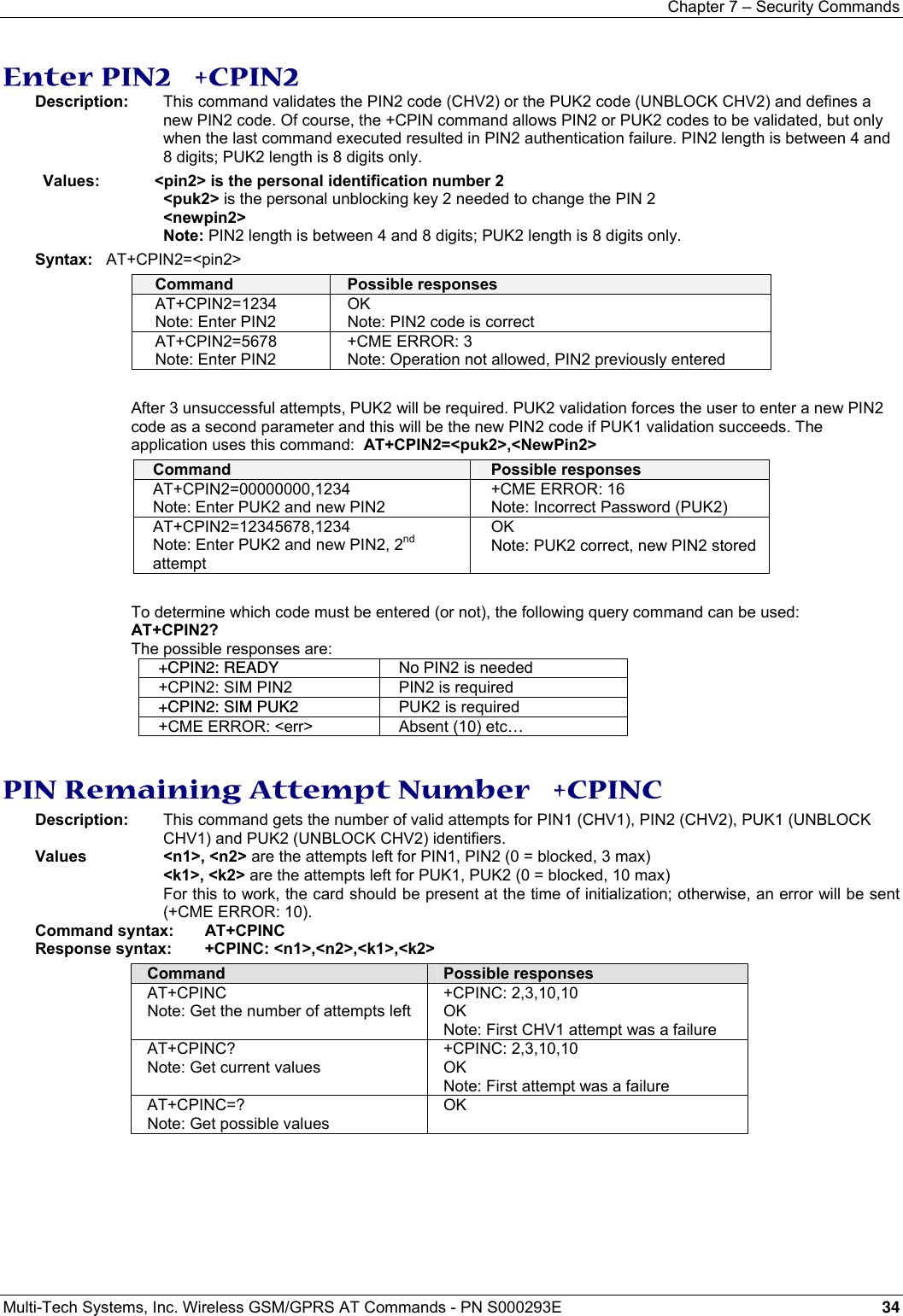
![Chapter 15 – Specific AT Commands Multi-Tech Systems, Inc. Wireless GSM/GPRS AT Commands - PN S000293E 88 • Combination of the requested dump is supported (addition of the values 1, 2, 4, and 8): Value Requested Dump Value Requested Dump 1 +CCED response: Main Cell only 9 +CSQ response; then +CCED response with Main Cell only 2 +CCED response: Neighbors 1 to 6 10 +CSQ response; then +CCED response with Neighbors 1 to 6 3 +CCED response: Main Cell; then Neighbors 1 to 6 11 +CSQ response; then +CCED response with Main Cell; then Neighbors 1 to 6 4 +CCED response: Timing Advance Only 12 +CSQ response; then +CCED response with Timing Advance Only 5 +CCED response: Main Cell; then Timing Advance 13 +CSQ response; then +CCED response with Main Cell; then Timing Advance 6 +CCED response: Neighbors 1 to 6; then Timing Advance 14 +CSQ response; then +CCED response with Neighbors 1 to 6; then Timing Advance 7 +CCED response: Main Cell; then Timing Advance; then Neighbors 1 to 6; with each Timing Advance inserted between cell’s results 15 +CSQ response; then +CCED response with Main Cell, then its Timing Advance; then Neighbors 1 to 6; with each Timing Advance inserted between cell’s results 8 +CSQ response: Main Cell RSSI indications No value Last value used for +CCED request or 15 • If requested dump parameter is not provided, one of the last +CCED commands sill be used (or 15 by default) will be used. • Values of MCC/MNC are set to 0 in the case of “No service”. Command syntax: AT+CCED=<mode>[, <requested dump>] Command Possible responses AT+CCED=0 Note: Last request was AT_CCED=0,3 (main cell and neighbors 1 to 6): you can see MCC,MNC sequences (here 208,20) +CCED:208,20,0002,0418,37,706,24,,,0,,,0,208,20,0006,989b,37,835,20,208,,20,0002,02a9,37,831,12,208,20,0101,7966,34,818,508,20,0006,9899,39,713,9,208,20,0002,0a72,33,711,12,208,20,0101,03fb,36,824,10,1 OK AT+CCED=0,1 Note: Only Main Cell request +CCED:208,20,0002,0418,37,706,25,,,0,,,0 OK AT+CCED=0,1 Note: Call in progress: RxLev and RxQual are empty, RxLevFull, RxLevSub, RxQualFull, and RxQualSub have data +CCED:208,10,189C,,19,85,,31,32,,0,0 OK](https://usermanual.wiki/Multi-Tech-Systems/92U07A31817/User-Guide-789840-Page-88.png)
![Chapter 15 – Specific AT Commands Multi-Tech Systems, Inc. Wireless GSM/GPRS AT Commands - PN S000293E 90 Command syntax: AT+WIND= <IndLevel > Command Possible responses AT+WIND? +WIND: 0 OK AT+WIND=255 OK Note: The SIM has been removed. +WIND: 0 Note :The SIM presence pin has been detected as “SIM inserted” Note: The SIM has been removed. +WIND: 1 Note :The SIM presence pin has been detected as “SIM inserted” Note: The network service is available for an emergency call +WIND: 7 Note: The initialization has been completed +WIND: 4 Additional Notes: • The AT+WIND? command is supported and indicates the <allowed bit flows>. • AT+WIND settings are automatically stored in non volatile memory (EEPROM). This means the &W command does not need to be used and the selected flows are always activated after boot. • Default value is 0: no flow activated, no indication. • AT+WIND=? gives the possible value range (0-4095) • The unsolicited response will then be: +WIND: <event> [ ,<idx> ] <idx>: Call identifier, defined in +CLCC command. • Or for event 10: +WIND: <event>,<phonebook>,<status>,…,<phonebook>,<status> • Or for event 11: +WIND: <event>,[“<checksum of SM>”],[“<checksum of FD>”],[“<checksum of ON>”],[“<checksum of SN>”] ,[“<checksum of EN>”],[“<checksum of LD>”] Analog Digital Converter Measurements +ADC Description: This command gets the (DC level * 1024) of ADC A and ADC B, and possibly ADC C. These voltages are coded on 10 bits. Values: <n> 0 Select 2 converters 1 Select 3 converters <ADCValA> ADC A value, coded on 10 bits. The value returned includes the resistor bridge. Values are updated every 10 seconds. Displayed on modes 0 and 1. <ADCValB> ADC B value, coded on 10 bits. Displayed on modes 0 and 1. <ADCValC> ADC C value, coded on 10 bits. Displayed on mode 1 only. Command syntax: AT+ADC Command Possible responses AT+ADC=? Note: Ask for the list of possible values +ADC: (0-1) Note: possible values 0 or 1 AT+ADC=0 Note: Select 2 converters (mode 0) OK Note: 2 converters mode selected AT+ADC? Note: Ask for the current values of converters in mode 0 +ADC: 500,412 OK Note: ADC A, ADC B on 10 bits AT+ADC=1 Note: Select 3 converters (mode 1) OK Note: 3 converters mode selected AT+ADC? Note: Ask for the current values of converters in mode 1 +ADC: 712,698,997 OK Note: ADC A, ADC B, ADC C on 10 bits](https://usermanual.wiki/Multi-Tech-Systems/92U07A31817/User-Guide-789840-Page-90.png)
![Chapter 15 – Specific AT Commands Multi-Tech Systems, Inc. Wireless GSM/GPRS AT Commands - PN S000293E 92 Indicator Control +CIND Description: This command is used to read or set the values of ME indicators. If ME does not allow setting of indicators or if ME is not currently reachable, an error code is returned. Values: <ind> interger type value, which shall be in rante of corresponding <desc>: 0 Indicator is OFF or in a state that can be identified as an “OFF” state. 1 Indicator is ON or in a state that is more substantial than the “OFF” state. 2 This value is more substantial than 1, and so on. Note: If the indicator is a simple ON/OFF style element, it has only values 0 and 1. <desc> battchg: Battery charge level (0-5) signal: Signal quality (0-5) service: Service availability (0-1) message: Message received (0-1) call: Call in progress (0-1) roam: Roaming memory storage status in the MT (0-1) smsfull: SMS memory storage status in the MT (0-1) 0 Memory locations are available. 1 Memory full. Command syntax: AT+CIND=[<ind>[,<ind>[,…]]] Response syntax: +CIND: <ind>[,<ind>[,…]] or +CIND: (<desc>,(list of supported <ind>s))[,(<desc>,(list of supported <ind>s)) [,…]] Command Possible responses AT+CIND=[<ind>[,<ind>[,…]]] Note: Ask for key press event report +CME ERROR: <err> Note: ME not reachable AT+CIND? Note: read ME indicators current values +CIND: <ind>[,<ind>[,…]] AT+CIND=? Note: read ME indicators possible values +CIND: (<desc>,(list of supported <ind>s))[,(<desc>,(list of supported <ind>s)) [,…]] OK AT+CIND? +CIND: 1,2,1,1,0,0,0 Note: battchg:1 – max=5, signal:2 - max=5, service:1 – we are registered on the network, message:1 – an SMS has been received, call:0 – no call in progress, roam:0 – not roaming, smsfull:0 – SIM card is not full of SMS AT+CIND=? Note: read possible value for ME indicators +CIND: (“battchg”,(0-5)),(“signal”,(0-5)),(“service”:(0-1)),(“message”,(0-1)),(“call”,(0-1)),(“roam”,(0-1)),(“smsfull”,(0-1)) OK](https://usermanual.wiki/Multi-Tech-Systems/92U07A31817/User-Guide-789840-Page-92.png)
![Chapter 15 – Specific AT Commands Multi-Tech Systems, Inc. Wireless GSM/GPRS AT Commands - PN S000293E 93 Mobile Equipment Control Mode +CMEC Description: This command selects the equipment that operates the ME keypad, writes to the ME display, and sets the ME indicators. If operation mode is not allowed by the ME, +CME ERROR: <err> is returned. Values: <keyp> (keypad): 0 ME can be operated only through its keypad (execute command of +CKPD cannot be used). 1 ME can be operated only from TE (with command +CKPD). 2 ME can be operated only from both TE keypad and TE. <idsp> 0 Only ME can write to its display (only command +CDIS can be used to read the indicators). 1 Only TE can write to ME display (with command +CDIS). 2 ME display can be written by both ME and TE. <ind> 0 Only ME can set the status of its indicators (command +CIND can only be used to read the indicators). 1 Only TE can set the status of ME indicators (with command +CIND). 2 ME indicators can be set by both ME and TE Command Syntax: AT+CMEC=[<keyp>[,<disp>[,<ind>]]] Response Syntax: +CMEC: <keyp>,<disp>,<ind> Command Possible responses AT+CMEC=[<keyp>[,<disp>[,<ind>]]] +CME ERROR: <err> AT+CMEC=[<keyp>[,<disp>[,<ind>]]] OK AT+CMEC? +CMEC: 2,0,0 OK AT+CMEC=? +CMEC: (2),(0),(0) OK Note: no change allowed Read Language Preference +WLPR Description: Read a Language Preference value of EF-LP. The first indices should have the highest priority. Values: <index> Offset in the available languages range (SIM dependent) <value> Values for language Language example: <value> Language <value> Language 0 German 10 Norwegian 1 English 11 Greek 2 Italian 12 Turkish 3 French 13 Hungarian 4 Spanish 14 Polish 5 Dutch 32 Czech 6 Swedish 33 Hebrew 7 Danish 34 Arabic 8 Portuguese 35 Russian 9 Finnish 36 Icelandic Command syntax: AT+WLPR= <index > Response syntax: +WLPR: <value> Command Possible responses AT+WLPR? Note: Read command +WLPR: 4 OK Note: Four language preferences are available in EF-LP AT+WLPR=1 Note: Read first EF-LP index value +WLPR: 5 OK Note: Language preference is 5](https://usermanual.wiki/Multi-Tech-Systems/92U07A31817/User-Guide-789840-Page-93.png)

![Chapter 15 – Specific AT Commands Multi-Tech Systems, Inc. Wireless GSM/GPRS AT Commands - PN S000293E 95 Input/Output Management +WIOM Description: This command sets the default GPIOs configuration (input or output) after reset, and each GPIO default value (if set as an output) after reset. Note: This command is allowed only on a GPIO not allocated by the Open-AT embedded application or for bus operations. Values: <GpioDir> Bit table parameter indicating each GPIO direction. 0 Input 1 Output. Default. Default value: 255 (all GPIOs set as outputs). <GpioVal> Bit table parameter indicating each output-configured GPIO value (each bit gives the corresponding GPIO default value). 0 Reset. Default. 1 Set The GPIOs set as inputs by the <GpioDir> parameter are not affected by the value set by the <GpioVal> parameter. Notes: • <GpioDir> bit values for GPI and GPO are ignored. • <GpioVal> bit values for GPI are ignored. Command Syntax AT+WIOM=[<GpioDir>],[<GpioVal>] Command Possible responses AT+WIOM? +WIOM: 255,0 OK On reset, all GPIOs are set to 0, as an output. AT+WIOM=? +WIOM: (0-255),(0-255) OK Range allowed for the parameters. AT+WIOM=254 Set GPIO 0 as an input, and all others as outputs.OK AT+WIOM=,128 Set GPIO 7 default output value to 1. OK AT+WIOM? +WIOM: 254,128 OK Abort Command +WAC Description: This command allows SMS, SS and PLMN selection related commands to be aborted. Values: No parameters Command syntax: AT+WAC Example: Command Syntax Return Command Possible responses AT+WAC AT+COPS=? Note: Available PLMN AT+WAC=? OK AT+WAC Note: Abort the request of PLMN list OK AT+WAC? OK](https://usermanual.wiki/Multi-Tech-Systems/92U07A31817/User-Guide-789840-Page-95.png)
![Chapter 15 – Specific AT Commands Multi-Tech Systems, Inc. Wireless GSM/GPRS AT Commands - PN S000293E 96 Play Tone +WTONE Description: This command allows a tone to be played on the current speaker or on the buzzer. Frequency, gain and duration can be set. Values: <mode> 0 Stop playing. 1 Play a tone <dest> Sets the destination (mandatory if <mode>=1) 1 Speaker 2 Buzzer <freq> Sets tone frequency (in Hz) (mandatory if <mode>=1). 1 Speaker. Range is between 1Hz and 3999Hz. 2 Buzzer. Range is between 1Hz and 50000Hz. <gain> (0-15): Sets the tone gain. Range is 0 to 15. Default 9. <gain> Speaker (db) Buzzer (db) 0 0 -0.25 1 -0.5 -0.5 2 -1 -1 3 -1.5 -1.5 4 -2 -2 5 -3 -3 6 -6 -6 7 -9 -9 8 -12 -12 9 -15 -15 10 -18 -18 11 -24 -24 12 -30 -30 13 -36 -40 14 -42 -infinite 15 -infinite -infinite <duration> (0-50) Sets tone duration (unit of 100 ms). Range is 0 to 50. Default 0. When this parameter is equal to 0, the duration is infinite, and the tone can be stopped by AT+WTONE=0. Command syntax: AT+WTONE=<mode>[,<dest>,<freq>,<gain>,<duration>] Response syntax: OK or +CME ERROR: <err> Command Possible responses AT+WTONE=1,1,300,9,50 Note: Play a tone OK Note: Done AT+WTONE=0 Note: Stop playing OK Note: Done AT+WTONE=? Note: Test command OK Note: Done AT+WTONE? Note: Current value ERROR](https://usermanual.wiki/Multi-Tech-Systems/92U07A31817/User-Guide-789840-Page-96.png)
![Chapter 15 – Specific AT Commands Multi-Tech Systems, Inc. Wireless GSM/GPRS AT Commands - PN S000293E 97 Play DTMF Tone +WDTMF Description: This command allows a DTMF tone to be played on the current speaker. DTMF, gain, and duration can be set. This command is only used to play a DTMF tone. To send a DTMF over the GSM network, use the +VTS command. Values: <mode> 0 Stop playing. 1 Play a DTMF tone <dtmf> Sets the DTMF to play in (mandatory if <mode>=1). Value must be in {0-9,*,#,A,B,C,D} <gain> (0-15) Sets tone gain. The values are identical to those of the +WTONE (speaker) command. Range is 0 to 15 (see array on previous page). By default, the value is 9. <duration> (0-50) Sets the tone duration (unit of 100 ms). Range 0 to 50. Default 0 (1-> 0,1 s., 50 -> 5 s.) When this parameter is 0 (default value), the duration is infinite, and the DTMF tone can be stopped by AT+WDTMF=0. Command syntax: AT+WDTMF=<mode>[,<dtmf>,<gain>,<duration>] Response syntax: OK or +CME ERROR: <err> Command Possible responses AT+WDTMF=1,"*",9,100 Note: Play a DTMF tone OK Note: Done AT+WDTMF=0 Note: Stop playing OK Note: Done AT+WDTMF=? Note: Test command +WDTMF: (0-1),(0-9,*,#,A,B,C,D),(0-15),(0-50) OK Note: Done AT+WDTMF? Note: Current value ERROR Downloading +WDWL Description: This command switches the product to download mode. Downloading is performed using the 1K-XMODEM protocol. Values: No parameters Command syntax: AT+WDWL Command Possible responses AT+WDWL Note: Switch on downloading mode +WDWL: 0 Note: Start the downloading … Note: Downloading in progress AT+CFUN=1 Note: Reset the product at the end OK Note: Reset completed. New software running](https://usermanual.wiki/Multi-Tech-Systems/92U07A31817/User-Guide-789840-Page-97.png)
![Chapter 15 – Specific AT Commands Multi-Tech Systems, Inc. Wireless GSM/GPRS AT Commands - PN S000293E 100 Ring Indicator Mode +WRIM Description: This command sets or returns the state of the Ring Indicator Mode. • In up-down RI mode, no pulses are sent before unsolicited AT response, and up-down signals are sent when receiving an incoming call. • In pulse RI mode, an electrical pulse is sent on the Ring Indicator signal just before sending any unsolicited AT response in order not to lose AT responses when client tasks are in sleep state. Still in RI mode, when receiving incoming calls, electrical pulses are sent on the RI signal. • Pulse RI Mode + Pulse On Packet Downloaded: based on Pulse RI mode but an electrical pulse is also sent on the Ring Indicator signal just before sending a downloaded data packet (GPRS or CSD) if the remote client has dropped down his RTS signal. Values: <mode> 0 Up-down RI mode 1 Pulse RI mode 2 Pulse RI mode + Pulse on Downloaded Packet <n> used only in mode RI Pulse + Pulse on Downloaded Packet (<mode>=2). 0 Duration of pulse is 5 µs 1-33 Duration of pulse is n x 30 µs Important: Pulse duration may be increased by up to 3 ms, due to interrupt processes overhead. Note: Remind that this mode corresponds to the case where the remote equipment has dropped its RTS signal to stop its flow control. Command syntax: AT+WRIM=<n> Command Possible responses AT+WRIM=<n> OK AT+WRIM=0 Note: Select up-down RI mode OK Note: up-down RI mode selected AT+WRIM=1 Note: Select pulse RI mode OK Note: pulse RI mode selected AT+WRIM=? Note: Ask the list of possible values +WRIM: (0-1) OK Note: possible values 0 or 1 AT+WRIM? Note: Ask the current value +WRIM: 1 OK Note: current RI mode is pulse RI. Command syntax: AT+WRIM=<mode>[,<n>] Command Possible responses AT+WRIM=0 Note: Select up-down RI mode OK Note: up-down RI mode selected AT+WRIM=1 Note: Select pulse RI mode OK Note: pulse RI mode selected AT+WRIM=2,0 Note: Select mode pulse RI + Pulse on downloaded packet; pulse duration is 5 µs OK Note: mode pulse RI + Pulse on downloaded packet selectedAT+WRIM=? Note: Ask for the list of possible values +WRIM: (0-2),(0-33) OK Note: possible values 0, 1, or 2 AT+WRIM? Note: Ask for the current value +WRIM: 1,0 OK Note: current RI mode is pulse RI.](https://usermanual.wiki/Multi-Tech-Systems/92U07A31817/User-Guide-789840-Page-100.png)
![Chapter 15 – Specific AT Commands Multi-Tech Systems, Inc. Wireless GSM/GPRS AT Commands - PN S000293E 102 Custom Character Set +WCCS Description: This command edits and displays the custom character set tables. The “CUSTOM” mode of +CSCS and the +WPCS commands use this character set. In this mode, when the user enters a string, this string is converted into GSM alphabet using the Custom To GSM table. In a similar way, when the user requests a string display, the string is converted from GSM alphabet using the GSM To Custom table. In edition mode, the edition session is terminated by <ctrl-Z>, or aborted by <ESC>. Only hexadecimal characters (‘0’…’9’, ‘A’…’F’) can be used. The number of characters entered must equal the edition range requested, otherwise the command will terminate with a “+CME ERROR: 3” result. Values: <mode> 0 Display the table 1 Edit the table <table> 0 Custom To GSM conversion table 1 GSM To Custom conversion table <char 1>, <char 2> Character range to display/edit. 0…127 for GSM To Custom conversion table 0…255 for Custom To GSM conversion table Note: If only <char 1> is present, only this char is displayed/edited. See Appendix C for informative examples on phonebooks. Command syntax: AT+WCCS=<mode>,<table>,<char 1>[,<char 2>] Command Possible responses AT+WCCS=0,0,120,130 Note: Display from character 120 to character 130 of the Custom To GSM conversion table +WCCS: 11, 78797A2020202020097E05 OK Note: 11 characters displayed AT+WCCS=1,0,115<CR> 20<ctrl-Z> Note: Edit character 115 of the Custom To GSM conversion table OK Note: Edition successful AT+WCCS=1,1,0,4<CR> 40A324A5E8<ctrl-Z> Note: Edit the 5 first characters of the GSM To Custom conversion tableOK Note: Edition successful AT+WCCS=1,1,200 Note: Edit character 200 of GSM To Custom conversion table +CME ERROR: 3 Note: Index out of range](https://usermanual.wiki/Multi-Tech-Systems/92U07A31817/User-Guide-789840-Page-102.png)
![Chapter 15 – Specific AT Commands Multi-Tech Systems, Inc. Wireless GSM/GPRS AT Commands - PN S000293E 103 Lock +WLCK Description: This command allows the ME to be locked on a specific network operator. Note: Test SIM cards (with MCC=001 & MNC=01) doesn’t check these locks. Values: <fac> “PS” SIM lock facility with a 8 digits password (PCK). “PN” Network lock with a 8 digits password (NCK). “PU” Network subset lock with a 8 digits password (NSCK). “PP” Service provider lock with a 8 digits password (SPCK). “PC” Corporate lock with a 8 digits password (CCK). <CnlType> Type of lock for co-operative network list (CNL) 0 Automatic (co-operative network list retrieved from EFCNL SIM file) Note: EFCNL file must be present in SIM to use automatic mode. 1 Manual (co-operative network list is given in the <CnlData> parameter) <CnlData> Co-operative network list (hexa string type) using same format as in EFCNL SIM file (ETSI GSM 11.11 or 3GPP 04.08). Note: Only if <CnlType> = 1 Command syntax: AT+WLCK=<fac>,<passwd>,<NetId>[,<GID1>[,GID2]] [,<CnlType>[,<CnlData>]] Response syntax: +WLCK: <status> Command Possible responses AT+WLCK="PN",12345678,20810 Note: Activate network lock on SFR (208,10) OK Note: Network lock activated AT+WLCK="PS",12345678,208105923568974 Note: Activate SIM lock OK Note: SIM lock activated AT+WLCK="PU",12345678,2081035 Note: Activate Network Subset lock on SFR (208, 10, 35). OK Note: Network Subset lock activated AT+WLCK="PU",12345678,20810 +CME ERROR: 3 Note: Need 7 digits of IMSI to perform a service provider lock AT+WLCK=”PP”,12345678,20810,”E5” Note: Activate Service Provider lock on SFR (208, 10) and GID1 (0xE5). OK Note: Service Provider lock activated. AT+WLCK=”PC”,12345678,20810,”E5”,”10” Note: Activate Corporate lock on SFR (208, 10), GID1 (0xE5) and GID2 (0x10). OK Note: Corporate lock activated. AT+WLCK=”PN”,12345678,20810,0 Note: Activate Network lock on SFR (208, 10) using co-operative network list from SIM file EFCNL (must be present in SIM) OK Note: Network lock activated on SFR and co-operative network list present in SIM AT+WLCK=”PN”,12345678,20801,1,”02F802FFFFFF02F801FFFFFF” Note: Activate Network lock on F ORANGE (208, 01) with manual co-operative network list including SFR (208, 10) and Bouygues Telecom (208, 20) OK Note: Network lock activated on F ORANGE (primary network), SFR and Bouygues Telecom (co-operative networks)](https://usermanual.wiki/Multi-Tech-Systems/92U07A31817/User-Guide-789840-Page-103.png)
![Chapter 15 – Specific AT Commands Multi-Tech Systems, Inc. Wireless GSM/GPRS AT Commands - PN S000293E 104 CPHS Command +CPHS Description: This command is used to activate, deactivate or interrogate a CPHS feature (e.g., Voice Mail Indicator, Mail Box Number…) Note: This command may answer +CME ERROR: 3 if the CPHS feature is disabled or if the SIM card does not support this CPHS feature. Values: <mode> 0 Deactivate a CPHS feature 1 Activate a CPHS feature 2 Interrogate a CPHS status Note: The deactivate or activate command has no effect on Alternate Line Service, Network Operator Name, CPHS Information, and Customer Profile Service features. <fctId> 1 Voice Mail Indicator 2 Mail Box Number 3 Alternate Line Service 4 Diverted Call Indicator 5 Network Operator Name 6 CPHS Information 7 Customer Service Profile Note: The Customer Profile Service and Alternate Line Service features are activated if the field is set in CPHS Information and CSP files. The Network Operator is activated if at least one of the two format names exist (Long or Short format). This is done in initialization. <precision> used only if <mode>=2 and <fctId> = 5 to 7 if <fctId>=5, this field is <type format> (See +WNON) if <fctId>=6, this field is <date field> (See +WCPI) if <fctId>=7, this field is <service> (See +WCSP) <Status> 0 CPHS feature disabled 1 CPHS feature enabled Command syntax: AT+CPHS=<Mode>,<FctId> Command Possible responses AT+CPHS=<Mode>,<FctId> [,precision] OK AT+CPHS=<Mode>,<FctId> [,precision] +CME ERROR: 3 AT+CPHS? +CPHS: <FctId1>,<Status><CR<LF> +CPHS: <FctId2>,<Status><CR<LF> … +CPHS: <FctIdn>,<Status><CR<LF> OK AT+CPHS= OK](https://usermanual.wiki/Multi-Tech-Systems/92U07A31817/User-Guide-789840-Page-104.png)
![Chapter 15 – Specific AT Commands Multi-Tech Systems, Inc. Wireless GSM/GPRS AT Commands - PN S000293E 107 Network Operator Name +WNON Description: This indication provides the name of the network operator (as a character string). This command is the response to the AT+CPHS 2,5 [,<type format>] command. Values: <type format> 0 Long format operator name 1 Short format operator name. Default. <operator name> The name of the operator in long or short format Command Syntax: AT+CHPS=2,5[,<type format>] Response Syntax: +WNON: <type format>,<operator name> Command Possible responses AT+CPHS=1,5 Note: Get Operator Name +WNON: 0,”Orange F” OK AT+CPHS=2,5,1 Note: Get short format Operator Name +WNON: 1,”Orange” OK AT+CPHS=2,5,0 +CME ERROR: 3 Note: CPHS feature is not allowed or format name is not accessible AT+CPHS=2,5,1 +CME ERROR: 3 Note: CPHS feature is not allowed or format name is not accessible AT+CPHS=2,5,1 Note: Deactivatation of Network Operator Name feature OK Note: No effect CPHS Information +WCPI Description: This indication provides CPHS information; i.e., which data fields are present in the SIM. This command is the response to the AT+CPHS 2,6 [,<data field>] command. Values: <data field> value indicating the field of CPHS information If <precision> field is omitted in the AT+CPHS command, all fields of CPHS Information will be displayed. <status> 0 data field is set 1 data field is unset When all CPHS Information is requested, the status corresponds to a bit field. Note: The field CSP Service (<data field> = 1) is used to set the CSP feature at initialization. Command Syntax: AT+CHPS=2,6[,<data field>] Response Syntax: +WCPI: <data field>,<status> Command Possible responses AT+CPHS=2,6 Note: Get current status for all CPHS Information fields+WCPI: 0,”0033000F” OK AT+CPHS=2,6,13 Note: Get the current status of Call Forward Activated Indicator for Line 1 +WCPI: 13,1 OK Note: Call Forward is active for Line 1 AT+CPHS=2,6,22 Note: Get current status for Line 2 Mailbox Number +WCPI: 22,0 OK Note: Mailbox Number for Line 2 is not available AT+CPHS=2,6,17 +CME ERROR: 3 Note: Wrong data field AT+CPHS=2,6,22 Note: Get current status for Line 2 Mailbox Number +CME ERROR: 3 Note: CPHS feature is not allowed AT+CPHS=0,6 Note: Deactivatation of CPHS Information feature OK Note: No effect](https://usermanual.wiki/Multi-Tech-Systems/92U07A31817/User-Guide-789840-Page-107.png)
![Chapter 15 – Specific AT Commands Multi-Tech Systems, Inc. Wireless GSM/GPRS AT Commands - PN S000293E 108 Customer Service Profile +WCSP Description: This indication tells whether or not a service is accessible to the customer. This command is the response to the AT+CPHS 2,7 [,<service>] command. Values: <service> value indicating the CSP field to display (See Appendix B). <status> 0 service is not customer-accessible 1 service is customer-accessible Note: The field Alternate Line Service (CPHS Teleservices Group) sets the ALS feature at initialization. Command Syntax: AT+CHPS=2,7[,<service>] Response Syntax: +WCSP: <service>,<status> Command Possible responses AT+WCSP=? ERROR AT+WCSP? ERROR AT+CPHS=2,7 +CME ERROR: 3 Note: Syntax error AT+CPHS=2,7,9 Note: Get current status of Barring All Outgoing Calls +WCSP: 9,1 OK Note: Barring or All Outgoing Calls is customer accessibleAT+CPHS=2,7,11 Note: Get current status of Barring All Outgoing International Calls +WCSP: 11,1 OK Note: Barring or All International Outgoing Calls is customer accessible AT+CPHS=2,7,2 Note: Get current status of Call Forwarding on User Busy +CME ERROR: 3 Note: CPHS feature is not allowed AT+CPHS=0,7 Note: Deactivatation of CPHS Information OK Note: No effect Customer Storage Mirror +WMIR Description: This command makes a mirror copy of the current configuration parameters in the EEPROM. In the case of a memory problem for the storage: if a customer mirror already exists, this one will be restored. Otherwise, the default mirrored parameters are restored. Values: No parameters Command syntax: AT+WMIR Command Possible responses AT+WMIR=? OK AT+WMIR Note: Build the Customer Mirror OK Change Default Player +WCDP Description: This command allows the default melody player to be selected. Values: <player> 0 Buzzer 1 Speaker Command syntax: AT+WCDP = <player> Command Possible responses AT+WCDP=? +WCDP: (0-1) OK AT+WCDP=0 Note: Select the buzzer OK AT+WCDP? +WCDP: 0 OK](https://usermanual.wiki/Multi-Tech-Systems/92U07A31817/User-Guide-789840-Page-108.png)
![Chapter 15 – Specific AT Commands Multi-Tech Systems, Inc. Wireless GSM/GPRS AT Commands - PN S000293E 110 Alternate Line Service +WALS Description: This command allows you to set and to get the active line. The CPHS command can be used to know which line is active. Values: <CmdType> 0 Set active line 1 Get active line <Lineld> Used only for <CmdType> 1 Line 1 2 Line 2 Command syntax: AT+WALS = <CmdType>[,<Lineld>] Response syntax: Response to AT+CPHS=2,3: +WALS = <Lineld> Command Possible responses AT+WALS? +WALS: 1 OK Note: Display current active line AT+WALS=? +WALS: (0-1),(1-2) OK AT+WALS = 0,1 Note: Activate Line 1 +WALS: 1 OK AT+WALS = 0,2 Note: Activate Line 2 +CME ERROR: 3 Note: When the ALS feature is not allowed AT+WALS = 1 Note: Get the current Active Line +WALS: 1 Note: Display the current Active Line AT+WALS = 1,2 +CME ERROR: 3 Note: Syntax error AT+CPHS=0,3 Note: Deactivation of ALS feature OK Note: No effect AT+CPHS=2,3 Note: Interrogate ALS feature +WALS: 1 Note: Display the current Active Line +CME ERROR: 3 Note: In the case where the ALS feature is not allowed Open AT Control Command +WOPEN Description: This command starts, stops, deletes, and gets information about the current Open AT embedded application. Note: This command is available only if the Open AT feature is enabled. Values: <Mode> 0 Stop the embedded application. If this one was running, the product resets 1 Start the embedded application. If this one was stopped, the product resets 2 Get the Open AT library versions 3 Erase the objects flash of Open-AT embedded application 4 Erase the Open AT embedded application Note: Mode = 3 and 4 are only available only if Open AT embedded application is stopped (AT+WOPEN=0). <IntVersion> ASCII string giving the internal Open AT library version. <ExtVersion> ASCII string giving the external Open AT library version. Note: If no embedded application is loaded, the <ExtVersion> parameter does not appear. Command syntax: AT+WOPEN=<Mode> Response syntax: +WOPEN: <Mode>[,<IntVersion>[<ExtVersion>]]](https://usermanual.wiki/Multi-Tech-Systems/92U07A31817/User-Guide-789840-Page-110.png)
![Chapter 15 – Specific AT Commands Multi-Tech Systems, Inc. Wireless GSM/GPRS AT Commands - PN S000293E 112 Set Standard Tone +WSST Description: This command sets and gets the sound level of the Standard Tones. Values: <sound level> 0 Max volume (default) 15 Min volume Range [0 ; 15] <ring tone level> 0 Max volume (default) 15 Min volume Range [0 ; 15] Command syntax: AT+WSST=[<sound level>][,<ring tone level>] Command Possible responses AT+WSST=0 Note: Set volume to Max. OK AT+WSST=15 Note: Set volume to Min. OK AT+WSST=,5 Note: Set ring tone level to 5 OK AT+WSST? Note: get current standard tones sound level +WSST: 15,5 OK Note: current standard tones level is 15 (min.), and ring tone level is 5. AT+WSST=? Note: supported parameters +WSST: (0-15),(0-15) OK Hang-up +WATH Description: This command disconnects the remote user, specifying a release cause and the location. In the case of multiple calls, all calls are released (active, on-hold and waiting calls). Values: <RelCause>: decimal value from 1 to 127 See table “Failure Cause from GSM 04.08 recommendation.” <location>: optional parameter (default value =0) values as defined in 04.08 0 user 1 private network serving the local user 2 public network serving the local user 3 transit network 4 public network serving the remote user 5 private network serving the remote user 7 international network 10 network beyond interworking point Note: “AT+WATH=0” is the same as “ath.” Command Syntax: AT+WATH=<RelCause>,<location> Command Possible responses AT+WATH=31 Note: Ask for disconnection with release cause=normal and location=USER OK Note: Every call, if any, are released AT+WATH=? +WATH: (1-127),(0-5,7,10) AT+WATH=17,2 Note: Ask for disconnection with release cause=user busy and location= public network serving the local user OK Note: Every call, if any, are released](https://usermanual.wiki/Multi-Tech-Systems/92U07A31817/User-Guide-789840-Page-112.png)
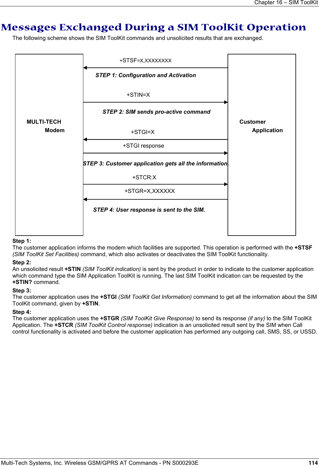
![Chapter 16 – SIM ToolKit Multi-Tech Systems, Inc. Wireless GSM/GPRS AT Commands - PN S000293E 115 SIM Toolkit Commands SIM ToolKit Set Facilities +STSF Description: This command allows SIM ToolKit facilities to be activated, deactivated or configured. Values: <mode> 0 Deactivates the SIM ToolKit functionalities. 1 Activates the SIM ToolKit functionalities. 2 Configures the SIM ToolKit functionalities. <Config> (160060C01F – 5FFFFFFF7F) (hex format) <Timeout> 1-255 Timeout for user responses (multiple of 10 seconds). <Autoresponse> 0 Automatic response is not activated 1 Automatic response is activated Notes about Autoresponse: • The activation or deactivation of the SIM ToolKit functionalities requires the use of the +CFUN (Set phone functionality) command to reset the product (this operation is not necessary if PIN is not entered yet). • The <Config> parameter gives the coding of the TERMINAL PROFILE, precisely the list of SIM Application ToolKit facilities that are supported by the customer application. • The <Timeout> parameter (multiple of 10 seconds) sets the maximum time the user has for reacting (to select an item, to input a text, etc). • When the <Autoresponse> is activated, the +STIN indication for Play Tone (5), Refresh (7), Send SS (8), Send SMS (9) or Send USSD (10) is automatically followed by the corresponding +STGI response. Note about Bits: Some bits are related to the product only and not to the customer application. The product automatically sets these bits to either 0 or 1 whatever the user enters with the +STSF command. Those values are given in Appendix D. Each facility is coded on 1 bit: • bit = 1: facility is supported by the customer application. • bit = 0: facility is not supported by the customer application. Only the first five bytes of the TERMINAL PROFILE (Class 2) can be configured. The other are set to 0. (See structure of TERMINAL PROFILE in APPENDIX E.) Command syntax: +STSF=<mode>[,<config>][,<Timeout>][,<AutoResponse>] Command Possible responses AT+STSF=<Mode>[,<Config>] [,<Timeout>][,<AutoResponse>] OK +CME ERROR: <err> AT+STSF? +STSF: <Mode>,<Config>,<Timeout>,<Autoresponse> AT+STSF=? +STSF: (0-2), (160060C01F - 5FFFFFFF7F),(1-255),(0-1) OK](https://usermanual.wiki/Multi-Tech-Systems/92U07A31817/User-Guide-789840-Page-115.png)
![Chapter 16 – SIM ToolKit Multi-Tech Systems, Inc. Wireless GSM/GPRS AT Commands - PN S000293E 118 SIM ToolKit Get Information +STGI Description: This command allows to get the information (text to display, menu information, priorities) of a pro-active command sent from the SIM. The information is returned only after receiving a SIM ToolKit indication (+STIN).) Values: Values are listed after the Command Table Command syntax: +STGI=<CmdType> Command Possible responses AT+STGI=<CmdType> See Table 1 +CME ERROR: <err> AT+STGI=? +STGI: (0-11) OK Table of Command Types Cmd Type Description Possible responses 0 Get information about Setup Menu pro-active command. +STGI: <Alpha Identifier menu> +STGI: <Id1>,<NbItems>,<Alpha Id1 Label>,<Help Info>[,<NextActionId>]<CR><LF>+STGI: <Id2>,<NbItems>,<Alpha Id2 Label>,<Help Info>[,<NextActionId>]<CR><LF>[…]] No action expected from SIM. 1 Get information about Display text pro-active command. +STGI: <Prior>,<Text>,<ClearMode> No action expected from SIM. 2 Get information about Get Inkey pro-active command. +STGI: <Format>,<HelpInfo>[,<TextInfo>] SIM expects key pressed (+STGR). 3 Get information about Get Input pro-active command. +STGI: <Format>,<EchoMode>,<SizeMin>,<SizeMax>, <HelpInfo>[,<TextInfo>] SIM expects key input (+STGR). 4 Get information about Setupt call pro-active command. +STGI: <Type>,<CalledNb>,<SubAddress>,<Class> SIM expects user authorization (+STGR). 5 Get information about Play Tone pro-active command. +STGI: <ToneType>[,<TimeUnit>,<TimeInterval>,<TextInfo>] No action. 6 Get information about Sel Item pro-active command. +STGI: <DefaultItem>, <Alpha Identifier menu><CR><LF> +STGI: <Id1>,<NbItems>,<Alpha Id1 Label>,<Help Info>[,<NextActionId>]<CR><LF>+STGI: <Id2>,<NbItems>,<Alpha Id2 Label>,<Help Info>[,<NextActionId>]<CR><LF>[…]] SIM expects an item choice (+STGR). 7 Get information about Refresh pro-active command. +STGI: <RefreshType> No action (Refresh done automatically by product). 8 Get information about Send SS pro-active command. +STGI:<TextInfo> No action (Send SS done automatically by product). 9 Get information about Send SMS pro-active command. +STGI: <TextInfo> No action (Send SMS done automatically by product). 10 Get information about Send USSD pro-active command. +STGI: <TextInfo> No action (Send USSD done automatically by product). 11 Get information about SETUP EVENT LIST pro-active command. +STGI: <Evt> Values for the SIM ToolKit Get Information Command: Values when CmdType=0 (Setup menu) <Alpha Idenitifer menu> Alpha identifier of the main menu. <Idx> (1-255) Menu item Identifier. <NbItems> (1-255) Number of items in the main menu. <Alpha Idx Label> Alpha identifier label of items in ASCII format. <HelpInfo> 0 No help information available. 1 Help information available. <NextActionId> Contains a pro-active command identifier.(see the table in APPENDIX F) Compared to other commands the customer application can always get information about setup menu after having received the +STIN:0 indication.](https://usermanual.wiki/Multi-Tech-Systems/92U07A31817/User-Guide-789840-Page-118.png)
![Chapter 16 – SIM ToolKit Multi-Tech Systems, Inc. Wireless GSM/GPRS AT Commands - PN S000293E 121 Unsolicited Result: SIM ToolKit Control Response +STCR Description: When the customer application makes an outgoing call or an outgoing SMS and if the call control facility is activated, CALL CONTROL and SMS CONTROL responses can be identified. This is also applicable to SS calls.) Values: <Result> 0 Control response not allowed. 1 Control response with modification. <Number> Called number, Service Center Address or SS String in ASCII format. <MODestAddr> MO destination address in ASCII format. <TextInfo> Text information in ASCII format. Command Syntax: +STCR: <Result>[,<Number>,<MODestAddr>,<TextInfo>] SIM ToolKit Give Response +STGR Description: This command allows the application/user to select an item in the main menu, or to answer the following proactive commands:) • GET INKEY Key Pressed By The User. • GET INPUT Message Entered By The User. • SELECT ITEM Selected Item. • SETUP CALL User Confirmation. • DISPLAY TEXT User Confirmation To Clear The Message. • SETUP EVENT LIST Reporting events. It is also possible to terminate the current proactive command session by sending a Terminal Response to the SIM, with the following parameters: • BACKWARD MOVE Process a backward move • BEYOND CAPABILITIES Command beyond ME capabilities • UNABLE TO PROCESS ME is currently unable to process command • NO RESPONSE No response from the user • END SESSION User abort. Command syntax: +STGR=<CmdType>[,<Result>,<Data>] Command Possible responses AT+STGR=<CmdType>[,<Result>,<Data>] OK +CME ERROR: <err> For GetInput with <Result>=1: AT+STGR=3,1<CR> <Data><Ctrl Z> OK +CME ERROR: <err> For GetInkey with <Result>=1 AT+STGR=2,1,”<Data>” OK +CME ERROR: <err> AT+STGR=? OK](https://usermanual.wiki/Multi-Tech-Systems/92U07A31817/User-Guide-789840-Page-121.png)
![Chapter 17 – GPRS Commands Multi-Tech Systems, Inc. Wireless GSM/GPRS AT Commands - PN S000293E 125 Command Syntax: Command Possible responses AT+CGDCONT=[<cid> [,<PDP_type> [,<APN> [,<PDP_addr> [,<d_comp> [,<h_comp>]]]]]] OK ERROR AT+CGDCONT? +CGDCONT: <cid>, <PDP_type>, <APN>,<PDP_addr>, <data_comp>, <head_comp> [<CR><LF>+CGDCONT: <cid>, <PDP_type>, <APN>,<PDP_addr>, <data_comp>, <head_comp> [...]] OK AT+CGDCONT=? +CGDCONT: (range of supported <cid>s), <PDP_type>,,,(list of supported <d_comp>s), (list of supported <h_comp>s) [<CR><LF>+CGDCONT: (range of supported <cid>s), <PDP_type>,,,(list of supported <d_comp>s),(list of supported <h_comp>s) [...]] OK AT+CGDCONT: 1, “IP” “internet”; AT+CGCONT=? +CGCONT: (1-4), “IP”,,,(0-1,(0-1) +CGCONT: (1-4), “PPP”,,,0,0,0 OK AT+CGCONT? +CGCONT: 1, “IP”,”internet”,,0,0 +CGCONT: 2, “IP”,”abc.com”,,0,0 OK](https://usermanual.wiki/Multi-Tech-Systems/92U07A31817/User-Guide-789840-Page-125.png)
![Chapter 17 – GPRS Commands Multi-Tech Systems, Inc. Wireless GSM/GPRS AT Commands - PN S000293E 126 Quality of Service Profile Requested +CGQREQ Description: This command allows the DTE to specify a Quality of Service Profile that is used when the modem sends an Activate PDP Context Request message to the network. The set command specifies a profile for the context identified by the local context identification parameter, <cid>. Since this is the same parameter that is used in the +CGDCONT command, the +CGQREQ command is effectively an extension to the +CGDCONT command. The QoS profile consists of a number of parameters, each of which may be set to a separate value. A special form of the set command, +CGQREQ= <cid>, causes the requested profile for context number <cid> to become undefined. The read command returns the current settings for each defined context. The test command returns values supported as a compound value. If the modem supports several PDP types, the parameter value ranges for each PDP type are returned on a separate line. Command Syntax: Command Possible Response(s) AT+CGQREQ=[<cid> [,<precedence > [,<delay> [,<reliability.> [,<peak> [,<mean>]]]]]] OK ERROR AT+CGQREQ? +CGQREQ: <cid>, <precedence >, <delay>, <reliability>, <peak>, <mean> [<CR><LF>+CGQREQ: <cid>, <precedence >, <delay>, <reliability.>, <peak>, <mean> […]] OK AT+CGQREQ=? +CGQREQ: <PDP_type>, (list of supported <precedence>s), (list of supported <delay>s), (list of supported <reliability>s) , (list of supported <peak>s), (list of supported <mean>s) [<CR><LF>+CGQREQ: <PDP_type>, (list of supported <precedence>s), (list of supported <delay>s), (list of supported <reliability>s) , (list of supported <peak>s), (list of supported <mean>s) […]] OK AT +CGQREQ=1,1,4,5,2,14 OK AT+CGQREQ=? +CGQREG: “IP”, (1-3), (1-4), (1-5), (1-9), (1-31) +CGQREQ: “PPP”, (1-3), (1-4), (1-5), (1-9), (1-31) OK AT+CGQREQ? +CGQREQ: 1,1,4,5,2,14 OK Summary List of Values: <cid>: a numeric parameter that specifies a particular PDP context definition. <precedence>: a numeric parameter that specifies the precedence class <delay>: a numeric parameter that specifies the delay class <reliability>: a numeric parameter that specifies the reliability class <peak>: a numeric parameter that specifies the peak throughput class <mean>: a numeric parameter that specifies the mean throughput class Note: If a value is omitted for a particular class then the value is considered to be unspecified. Details about Values: <cid> Range 1- 3 <precedence> 0 Subscribed precedence - Subscribed by the Network by default if value is omitted 1 High priority - Service commitments shall be maintained ahead of precedence classes 2 and 3 2 Normal priority - Service commitments shall be maintained ahead of precedence class 3 3 Low priority - Service commitments shall be maintained after precedence classes 1 and 2 <delay> 0 Subscribed 1 Delay class 1 2 Delay class 2 3 Delay class 3 4 Delay class 4](https://usermanual.wiki/Multi-Tech-Systems/92U07A31817/User-Guide-789840-Page-126.png)
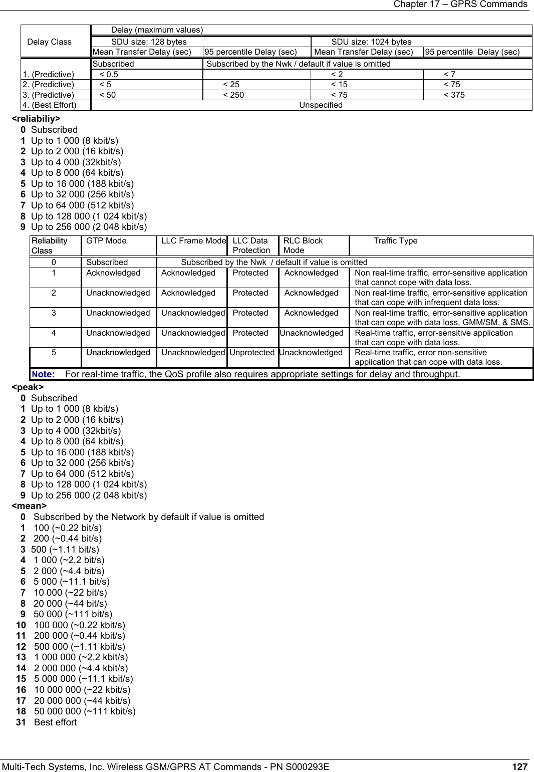
![Chapter 17 – GPRS Commands Multi-Tech Systems, Inc. Wireless GSM/GPRS AT Commands - PN S000293E 128 Quality of Service Profile Minimum Acceptable +CGQMIN Description: This command allows the DTE to specify a minimum acceptable profile which is checked by the modem against the negotiated profile returned in the Activate PDP Context Accept message. The set command specifies a profile for the context identified by the local context identification parameter, <cid>. Since this is the same parameter that is used in the +CGDCONT command, the +CGQMIN command is effectively an extension to the +CGDCONT command. The QoS profile consists of a number of parameters, each of which may be set to a separate value. A special form of the set command, +CGQMIN= <cid> causes the minimum acceptable profile for context number <cid> to become undefined. In this case no check is made against the negotiated profile. The read command returns the current settings1 for each defined context. The test command returns values supported as a compound value. If the modem supports several PDP types, the parameter value ranges for each PDP type are returned on a separate line. Values: <cid>: a numeric parameter which specifies a particular PDP context . <precedence>: a numeric parameter which specifies the precedence class. <delay>: a numeric parameter which specifies the delay class. <reliability>: a numeric parameter which specifies the reliability class. <peak>: a numeric parameter which specifies the peak throughput class. <mean>: a numeric parameter which specifies the mean throughput class. Note: If a value is omitted for a particular class then this class is not checked. Command Syntax: Command Possible Response(s) AT+CGQMIN=[<cid> [,<precedence > [,<delay> [,<reliability.> [,<peak> [,<mean>]]]]]] OK ERROR AT+CGQMIN? +CGQMIN: <cid>, <precedence >, <delay>, <reliability>, <peak>, <mean> [<CR><LF>+CGQMIN: <cid>, <precedence >, <delay>, <reliability.>, <peak>, <mean> […]] OK AT+CGQMIN=? +CGQMIN: <PDP_type>, (list of supported <precedence>s), (list of supported <delay>s), (list of supported <reliability>s) , (list of supported <peak>s), (list of supported <mean>s) [<CR><LF>+CGQMIN: <PDP_type>, (list of supported <precedence>s), (list of supported <delay>s), (list of supported <reliability>s) , (list of supported <peak>s), (list of supported <mean>s) […]] OK AT+CGQMIN = 1,1,4,5,2,31 OK AT+CGQMIN=? +CGQMIN: “IP”,(1-3),(1-4),(1-5),(1-9),(1-31) +CGQMIN: “PPP”,(1-3),(1-4),(1-5),(1-9),(1-31) OK AT+CGQMIN? +CGQMIN=? 1,1,4,5,2,14 OK](https://usermanual.wiki/Multi-Tech-Systems/92U07A31817/User-Guide-789840-Page-128.png)
![Chapter 17 – GPRS Commands Multi-Tech Systems, Inc. Wireless GSM/GPRS AT Commands - PN S000293E 129 GPRS Attach or Detach +CGATT Description: The execution command is used to attach the modem to, or detach the modem from, the GPRS service. After the command has completed, the modem remains in V.25ter command state. If the modem is already in the requested state, the command is ignored and the OK response is returned. If the requested state cannot be achieved, an ERROR or +CME ERROR response is returned. Extended error responses are enabled by the +CMEE command. Any active PDP contexts will be automatically deactivated when the attachment state changes to detached. The read command returns the current GPRS service state. The test command is used for requesting information on the supported GPRS service states. Values: <state>: indicates the state of GPRS attachment 0 Detached 1 Attached Other values are reserved and will result in an ERROR response to the execution command. Command Syntax: Command Possible Responses AT+CGATT= [<state>] OK ERROR AT+CGATT? +CGATT: <state> OK AT+CGATT=? +CGATT: (list of supported <state>s) OK AT+CGATT=1 OK](https://usermanual.wiki/Multi-Tech-Systems/92U07A31817/User-Guide-789840-Page-129.png)
![Chapter 17 – GPRS Commands Multi-Tech Systems, Inc. Wireless GSM/GPRS AT Commands - PN S000293E 130 PDP Context Activate or Deactivate +CGACT Description: The execution command activates or deactivates the specified PDP context (s). After the command has completed, the modem remains in V.25ter command state. If any PDP context is already in the requested state, the state for that context remains unchanged. If the requested state for any specified context cannot be achieved, an ERROR or +CME ERROR response is returned. Extended error responses are enabled by the +CMEE command. If the modem is not GPRS attached when the activation form of the command is executed, the modem first performs a GPRS attach and them attempts to activate the specified contexts. If the attach fails then the modem responds with ERROR or, if extended error responses are enabled, with the appropriate failure-to-attach error message. If no <cid>s are specified the activation form of the command activates the first activable defined contexts. If no <cid>s are specified the deactivation form of the command deactivates all active contexts. One PDP context can be activated at the same time. The read command returns the current activation states for all the defined PDP contexts. The test command is used for requesting information on the supported PDP context activation states. Values: <state>: indicates the state of PDP context activation 0 Deactivated 1 Activated Other values are reserved and will result in an ERROR response to the execution command. <cid>: a numeric parameter which specifies a particular PDP context. Before a context can be activated, the modem must be attached to the GPRS network by performing an automatic GPRS attach. Command Syntax: Command Possible Response(s) AT+CGACT=[<state> [,<cid>[,<cid>[,…]]]] OK ERROR AT+CGACT? +CGACT: <cid>, <state> [<CR><LF>+CGACT: <cid>, <state> [...]] OK AT+CGACT=? +CGACT: (list of supported <state>s) OK AT+CGACT=1,1 OK AT+CGACT? +CGACT: 1,1 OK AT+CGACT=? +CGACT: (0-1) OK](https://usermanual.wiki/Multi-Tech-Systems/92U07A31817/User-Guide-789840-Page-130.png)
![Chapter 17 – GPRS Commands Multi-Tech Systems, Inc. Wireless GSM/GPRS AT Commands - PN S000293E 131 Enter Data State +CGDATA Description: The command causes the modem to perform the necessary actions to set up communication between the DTE and the network. This may include performing a GPRS attach and one PDP context activations. If the <cid> value is not defined to the modem, the modem will return an ERROR or +CME ERROR response. Otherwise, the modem issues the intermediate result code CONNECT and enters V.25ter online data state. GPRS attachment and PDP context activation procedures may take place prior to or during the PDP startup if they have not already been performed using the +CGATT and +CGACT commands. If no <cid> is given, the modem attempts to activate the context with whatever information is available to the modem. The other context parameters is set to their default values (No APN, default QOS parameters, dynamic IP address requested). If the activation is successful, data transfer may proceed. After data transfer and layer 2 protocol termination procedure completion, the V.25ter command state is re-entered and the modem returns the final result code OK. In case of an abnormal termination or start up, the V.25ter command state is re-entered and the modem returns the final result code NO CARRIER or, if enabled, +CME ERROR. Attach, activate and other errors may be reported. This command may be used in both normal and modem compatibility modes. Note: The goal of this command is the same than ATD*99***. Values: <cid>: a numeric parameter which specifies a particular PDP context definition. Command Syntax: Command Possible Response(s) AT+CGDATA=[<cid>] CONNECT ERROR AT+CGDATA=? +CGDATA: OK AT+CGDATA=? +CGDATA: OK AT+CGDATA=1 CONNECT](https://usermanual.wiki/Multi-Tech-Systems/92U07A31817/User-Guide-789840-Page-131.png)
![Chapter 17 – GPRS Commands Multi-Tech Systems, Inc. Wireless GSM/GPRS AT Commands - PN S000293E 132 GPRS Mobile Station Class +CGCLASS Description: The set command is used to set the modem to operate according to the specified GPRS mobile class. If the requested class is not supported, an ERROR or +CME ERROR response is returned. The read command returns the current GPRS mobile class. The test command is used for requesting information on the supported GPRS mobile classes. Defined Values: <class>: a string parameter which indicates the GPRS mobile class (in descending order of functionality) A class A (highest) B class B CG class C in GPRS only mode CC class C in circuit switched only mode (lowest) Other values are reserved and will result in an ERROR response to the set command. If the modem is GPRS attached when the set command is issued with a <class> = CC specified, a GPRS detach request is sent to the network. If the modem is GSM attached when the set command is issued with a <class> = CG specified, a GSM detach request is sent to the network. Class A is not supported. Note: During switch-On in CG class, the modem always performs an automatic GPRS attach (the ATTACH-STATUS parameter of +WGPRS is ignored). But if the modem is not already GPRS- attached when switching from B/CC class to CG class, then no automatic GPRS attach is performed. About the automatic attachment (see Note above): AT+CGCLASS? +CGCLASS: “B” OK AT+CGATT? +CGATT: 0 OK AT+CGCLASS=”CG” OK AT+CGATT? +CGATT: 0 OK AT+CGATT=1 OK AT+CPOF OK AT+CFUN=1 OK AT+CGCLASS? +CGCLASS: “CG” OK AT+CGATT? +CGATT: 1 OK Command Syntax: Command Possible Response(s) AT+CGCLASS= [<class>] OK ERROR AT+CGCLASS? +CGCLASS: <class> OK AT+CGCLASS=? +CGCLASS: (list of supported <class>s) OK AT+CGCLASS=”CG” Note: Enter GPRS Class C mode OK AT+CGCLASS=”CC” Note: Enter GMS mode OK AT+CGCLASS=”A” Note: Chosen class not supported +CME ERROR: 150 AT+CGCLASS=? +CGCLASS: (“CG”,”CC”) OK AT+CGCLASS? +CGCLASS: (“CC”) OK](https://usermanual.wiki/Multi-Tech-Systems/92U07A31817/User-Guide-789840-Page-132.png)
![Chapter 17 – GPRS Commands Multi-Tech Systems, Inc. Wireless GSM/GPRS AT Commands - PN S000293E 133 Select Service for MO SMS Messages +CGSMS Description: The set command specifies the service or service preference that the modem will use to send MO SMS messages. The read command returns the currently selected service or service preference. The test command requests information on the currently available services and service preferences. Values: <service>: a numeric parameter which indicates the service or service preference to be used 0 GPRS 1 Circuit switched 2 GPRS preferred (use circuit switched if GPRS is not available) 3 Circuit switched preferred (use GPRS if circuit switched not available) Other values are reserved and will result in an ERROR response to the set command. Command Syntax: Command Possible Responses AT+CGSMS= [<service>] OK ERROR At+CGSMS? +CGSMS: <service> OK AT+CGSMS=? +CGSMS: (list of currently available <service>s) OK AT +CGSMS=0 OK AT+CGSMS=? +CGSMS=(0-3) OK](https://usermanual.wiki/Multi-Tech-Systems/92U07A31817/User-Guide-789840-Page-133.png)
![Chapter 17 – GPRS Commands Multi-Tech Systems, Inc. Wireless GSM/GPRS AT Commands - PN S000293E 134 GPRS Event Reporting +CGEREP Description: Set command enables or disables sending of unsolicited result codes, +CGEV: XXX from modem to DTE in the case of certain events occurring in the GPRS modem or the network. <mode> controls the processing of unsolicited result codes specified within this command. Read command returns the current mode and buffer settings. Test command returns the modes and buffer settings supported by the modem as compound values. Values: <mode>: 0 Buffer unsolicited result codes in the modem; if modem result code buffer is full, the oldest ones can be discarded. No codes are forwarded to the DTE. 2 Buffer unsolicited result codes in the modem when modem-DTE link is reserved (e.g. in on-line data mode) and flush them to the DTE when modem-DTE link becomes available; otherwise forward them directly to the DTE. <bfr> 0 Modem buffer of unsolicited result codes defined within this command is cleared when <mode> 1 or 2 is entered. This is the only case supported. 1 Modem buffer of unsolicited result codes defined within this command is flushed to the DTE when <mode> 2 is entered. This case is not supported. The software provides a combination of all modes. When a serial link is available, indications are forwarded directly to the DTE. If a serial link is reserved (e.g., in on-line data mode) or the modem result code buffer is full, the oldest ones can be discarded. Command Syntax: Command Possible Responses AT+CGEREP=[<mode>] OK ERROR AT+CGEREP? +CGEREP: <mode>,<bfr> OK AT+CGEREP=? +CGEREP: (list of supported <mode>s), (list of supported <bfr>s) OK Result Codes and Corresponding Events: The following unsolicited result codes and the corresponding events are defined: +CGEV: REJECT <PDP_type>, <PDP_addr> A network request for PDP context activation occurred when the modem was unable to report it to the DTE with a +CRING unsolicited result code and was automatically rejected. +CGEV: NW REACT <PDP_type>, <PDP_addr>, [<cid>] The network has requested a context reactivation. The <cid> that was used to reactivate the context is provided if known to the modem. +CGEV: NW DEACT <PDP_type>, <PDP_addr>, [<cid>] The network has forced a context deactivation. The <cid> that was used to activate the context is provided if known to the modem. +CGEV: ME DEACT <PDP_type>, <PDP_addr>, [<cid>] The mobile equipment has forced a context deactivation. The <cid> that was used to activate the context is provided if known to the modem. +CGEV: NW DETACH The network has forced a GPRS detach. This implies that all active contexts have been deactivated. These are not reported separately. +CGEV: ME DETACH The mobile equipment has forced a GPRS detach. This implies that all active contexts have been deactivated. These are not reported separately. +CGEV: NW CLASS <class> The network has forced a change of MS class. The highest available class is reported. +CGEV: ME CLASS <class> The mobile equipment has forced a change of MS class. The highest available class is reported.](https://usermanual.wiki/Multi-Tech-Systems/92U07A31817/User-Guide-789840-Page-134.png)
![Chapter 17 – GPRS Commands Multi-Tech Systems, Inc. Wireless GSM/GPRS AT Commands - PN S000293E 135 GPRS Network Registration Status +CGREG Description: The set command controls the presentation of an unsolicited result code +CGREG: <stat> when <n>=1 and there is a change in the modem's GPRS network registration status, or code +CGREG: <stat>[,<lac>,<ci>] when <n>=2 and there is a change of the network cell. The read command returns the status of result code presentation and an integer <stat> which shows whether the network has currently indicated the registration of the modem. Location information elements <lac> and <ci> are returned only when <n>=2 and modem is registered in the network. Values: <n> 0 Disable network registration unsolicited result code 1 Enable network registration unsolicited result code +CGREG: <stat> 2 Enable network registration and location information unsolicited result code +CGREG: <stat>[,<lac>,<ci>] <stat> 0 Not registered; the modem is not currently searching a new operator to which to register 1 Registered, home network 2 Not registered, but modem is currently searching a new operator to which to register 3 Registration denied 4 Unknown 5 Registered, roaming <lac> String type; two byte location area code in hexadecimal format <ci> String type; two byte cell ID in hexadecimal format Command Syntax: Command Possible response(s) AT+CGREG=[<n>] +CGREG: stat>[,<lac>,<ci>] OK AT+CGREG? +CGREG: <n>,<stat>[,<lac>,<ci>] OK Note: +CME ERROR: <err> AT+CGREG=? +CGREG: (list of supported <n>s) OK Request GPRS IP Service D Description: This command causes the modem to perform whatever actions are necessary to establish communication between the DTE and the external PDN. The V.25ter 'D' (Dial) command causes the modem to enter the V.25ter online data state and, with the DTE, to start the specified layer 2 protocol. The modem return CONNECT to confirm acceptance of the command prior to entering the V.25ter online data state. No further commands may follow on the AT command line. The detailed behavior after the online data state has been entered is described briefly in clause 9, for IP, of GSM 07.60. GPRS attachment and PDP context activation procedures may take place prior to or during the PDP startup if they have not already been performed using the +CGATT and +CGACT commands. If <cid> is supported, its usage is the same as in the +CGDATA command. The +CGDCONT, +CGQREQ, etc. commands may then be used in the modem initialization AT command string to set values for for PDP type, APN, QoS etc… If <cid> is not supported or is supported but omitted, the modem attempt to activate the context using the 'Empty PDP type' (GSM 04.08). (No PDP address or APN is sent in this case and only one PDP context subscription record is present in the HLR for this subscriber.) Values: <GPRS_SC_IP>: (GPRS Service Code for IP) a digit string (value 99), which identifies a request to use the GPRS with IP (PDP types IP and PPP) <cid>: a digit string which specifies a particular PDP context definition. Command Syntax: Command Possible Responses D*<GPRS_SC_IP>[***<cid>]# CONNECT ERROR Example: ATD*99***1# CONNECT ATD*99***2# ERROR](https://usermanual.wiki/Multi-Tech-Systems/92U07A31817/User-Guide-789840-Page-135.png)
![Chapter 17 – GPRS Commands Multi-Tech Systems, Inc. Wireless GSM/GPRS AT Commands - PN S000293E 137 Automatic Response to a Network Request for PDP Context Activation +CGAUTO Description: The set command disables or enables an automatic positive response (auto-answer) to the receipt of a Request PDP Context Activation message from the network. It also provides control over the use of the V.25ter basic commands 'S0', 'A and 'H' for handling network requests for PDP context activation. The setting does not affect the issuing of the unsolicited result code RING or +CRING. The test command returns values of <n> supported by the modem as a compound value. When the +CGAUTO=0 command is received, the modem will not perform a GPRS detach if it is attached. Subsequently, when the modem announces a network request for PDP context activation by issuing the unsolicited result code RING or +CRING, the DTE may manually accept or reject the request by issuing the +CGANS command or may simply ignore the network request. When the +CGAUTO=1 command is received, the modem will attempt to perform a GPRS attach if it is not already attached. Failure will result in ERROR or, if enabled, +CME ERROR being returned to the DTE. Subsequently, when the modem announces a network request for PDP context activation by issuing the unsolicited result code RING or +CRING to the DTE, this is followed by the intermediate result code CONNECT. The modem then enters V.25ter online data state and follows the same procedure as it would after having received a +CGANS=1 with <cid> values specified. Values: <n> 0 Turn off automatic response for GPRS only For <n> = 0 GPRS network requests are manually accepted or rejected by the +CGANS command. 1 Turn on automatic response for GPRS only For <n> = 1 GPRS network requests are automatically accepted according to the description above. 2 Modem compatibility mode, GPRS only For <n> = 2, automatic acceptance of GPRS network requests is controlled by the 'S0' command. Manual control uses the 'A' and 'H' commands, respectively, to accept and reject GPRS requests. (+CGANS may also be used.) Incoming circuit switched calls can be neither manually nor automatically answered 3 Modem compatibility mode, GPRS and circuit switched calls (default) For <n> = 3, automatic acceptance of both GPRS network requests and incoming circuit switched calls is controlled by the 'S0' command. Manual control uses the 'A' and 'H' commands, respectively, to accept and reject GPRS requests. (+CGANS may also be used.) Circuit switched calls are handled as described elsewhere in this specification. Note: In class C GPRS the modem can’t receive GPRS and GSM incoming calls simultaneously. Command Syntax: Command Possible response(s) AT+CGAUTO=[<n>] OK ERROR AT+CGAUTO? +CGAUTO: <n> OK AT+CGAUTO=? +CGAUTO: (0-3) OK Example: AT+CGAUTO=? +CGAUTO: (0-2) OK AT+CGAUTO? +CGAUTO: 2 OK AT+CGAUTO=0 OK](https://usermanual.wiki/Multi-Tech-Systems/92U07A31817/User-Guide-789840-Page-137.png)
![Chapter 17 – GPRS Commands Multi-Tech Systems, Inc. Wireless GSM/GPRS AT Commands - PN S000293E 138 Manual Response to a Network Request for PDP Context Activation +CGANS Description: The execution command requests the modem to respond to a network request for GPRS PDP context activation which has been signalled to the DTE by the RING or +CRING: unsolicited result code. The <response> parameter allows the DTE to accept or reject the request. If <response> is 0, the request is rejected and the modem returns OK to the DTE. If <response> is 1, the following procedure is followed by the modem. PDP context activation procedures take place prior to or during the PDP startup. One <cid> may be specified in order to provide the values needed for the context activation request. During the PDP startup procedure the modem has the PDP type and the PDP address provided by the network in the Request PDP Context Activation message. If a <cid> is given his informations must matching with the PDP type and PDP address in the network request as follows - The PDP type must match exactly. The PDP addresses are considered to match if they are identical or if the address in the context definition is unspecified. If any of this information is in conflict, the command will fail. The context is activated using the values for PDP type and PDP address provided by the network, together with the other information found in the PDP context definition. An APN may or may not be required, depending on the application. If no <cid> is given, the modem will attempt to activate the context using the values for PDP type and PDP address provided by the network, together with any other relevant information known to the modem. The other context parameters will be set to their default values. If the activation is successful, data transfer may proceed. After data transfer is complete, and the layer 2 protocol termination procedure has completed successfully, the V.25ter command state is re-entered and the modem returns the final result code OK. In the event of an erroneous termination or a failure to startup, the V.25ter command state is re-entered and the modem returns the final result code NO CARRIER or, if enabled, +CME ERROR. Attach, activate and other errors may be reported. It is also an error to issue the +CGANS command when there is no outstanding network request. This command may be used in both normal and modem compatibility modes. Values: <response>: is a numeric parameter which specifies how the request should be responded to. 0 reject the request 1 accept and request that the PDP context be activated If <response> is omitted it is assumed to be 0. Other values are reserved and will result in the ERROR response. <cid>: a numeric parameter which specifies a particular PDP context definition. Command Syntax: Command Possible response(s) AT+CGANS=[<response>, [<cid>]] OK ERROR AT+CGANS=? +CGANS: (list of supported <response>s), (list of supported <L2P>s) OK Example: +CRING: GPRS "IP", "122.41.74.238" AT+CGANS=1 CONNECT AT+CGANS=? +CGANS= (0-1) OK](https://usermanual.wiki/Multi-Tech-Systems/92U07A31817/User-Guide-789840-Page-138.png)
![Chapter 17 – GPRS Commands Multi-Tech Systems, Inc. Wireless GSM/GPRS AT Commands - PN S000293E 139 Show PDP Address +CGPADDR Description: The execution command returns a list of PDP addresses for the specified context identifiers. The test command returns a list of defined <cid>s. Values: <cid>: A numeric parameter which specifies a particular PDP context definition. If no <cid> is specified, the addresses for all defined contexts are returned. <PDP_address>: A string that identifies the modem in the address space applicable to the PDP. The address may be static or dynamic. For a static address, it will be the one set by the +CGDCONT command when the context was defined. For a dynamic address it will be the one assigned during the last PDP context activation that used the context definition referred to by <cid>. <PDP_address> is omitted if none is available. Command Syntax: Command Possible response(s) AT+CGPADDR=[<cid> [,<cid> [,…]]] +CGPADDR: <cid>,<PDP_addr> [<CR><LF>+CGPADDR: <cid>,<PDP_addr> [...]] OK AT+CGPADDR=? +CGPADDR: (list of defined <cid>s) OK Example: In this example, 3 <cid>s are defined: AT+CGPADDR=1 +CGPADDR=1,"107.210.5.4" OK AT+CGPADDR=? +CGAPDDR= (1-32) OK AT+CGPADDR +CGPADDR: 1, +CGPADDR: 2,"10.3.73.151" +CGPADDR: 3, +CGPADDR: 4, Cellular Result Codes +CRC Description: This command enables a more detailed ring indication, in case of incoming call (voice or data). Instead of the string “RING”, an extended string is used to indicate which type of call is ringing (e.g. +CRING: VOICE). These extended indications are: +CRING: ASYNC for asynchronous transparent +CRING: REL ASYNC for asynchronous non-transparent +CRING: VOICE for normal speech. +CRING: FAX for fax calls +CRING: GPRS GPRS network request for PDP context activation If the modem is unable to announce to the DTE the network's request (for example it is in V.25ter online data state) the modem reject the request. No corresponding unsolicited result code is issued when the modem returns to a command state. Values: No parameters Command Syntax: Command Possible responses AT+CRC=0 Note: Extended reports disabled OK Note: Command valid AT+CRC=1 Note: Extended reports enabled OK Note: Command valid AT+CRC? +CRC: 1 OK AT+CRC=? +CRC: (0,1) OK](https://usermanual.wiki/Multi-Tech-Systems/92U07A31817/User-Guide-789840-Page-139.png)
![Chapter 17 – GPRS Commands Multi-Tech Systems, Inc. Wireless GSM/GPRS AT Commands - PN S000293E 141 GPRS Parameters Customization +WGPRS Description: This command modifies some of the GPRS parameters, such as the ATTACH-STATUS (the modem doesn’t automatically make a GPRS attachment after initialization), the PDP-INIT-STATUS (activate automatically some defined PDP Contexts after initialization) and the use of NAT (IP address translation on PPP). In addition, this command permits the automatic setting of some PDP contexts after initialization. Note: The modem must be rebooted to activate the new setup. Values: <mode>: a numeric parameter which specifies a GPRS parameter: 0 ATTACH-STATUS (the modem doesn’t automatically make a GPRS attachment after init) 1 PDP-INIT-STATUS (automatically activate some define PDP Contexts after init) 2 Set ACTIVABLE automatically after init a define PDP context 3 NAT <parameter>: a numeric parameter that control the <mode> 0 Off 1 On <cid>: (PDP Context Identifier) a numeric parameter (1-32) which specifies a particular PDP context definition. The parameter is local to the DTE-modem interface and is used in other PDP context-related commands. Note: When the module is set in “CG” class, the modem always automatically makes a GPRS attachment after initialization, so AT+WGPRS? Always gives +WGPRS: 0,0 for the parameter 0. Command Syntax: AT+WGPRS AT+WGPRS=<mode>,<parameter>,[<cid>] OK ERROR AT+WGPRS=? +WGPRS: <mode>, <parameter1>,[<cid>] [<CR><LF>+WGPRS: <mode>, <parameter>,[<cid>] [...]] OK AT+WGPRS? +WGPRS:<mode>(list of supported <parameter>),[(list of supported <cid>)][<CR><LF>+WGPRS:<mode>(list of supported <parameter>),[(list of supported <cid>)] [...]] OK Example: AT+WGPRS=2,1,3 AT+WGPRS? +WGPRS: 2,0,3 OK +WGPRS: 0,0 +WGPRS: 2,0,4 AT+WGPRS=? +WGPRS: 1,0 +WGPRS: 3,1 +WGPRS: (0-3),(0-1),(0-4) +WGPRS: 2,1,1 OK OK +WGPRS: 2,0,2 <CR><LF>](https://usermanual.wiki/Multi-Tech-Systems/92U07A31817/User-Guide-789840-Page-141.png)
![Appendix A – Result Codes, Failure Causes, Other Tables Multi-Tech Systems, Inc. Wireless GSM/GPRS AT Commands - PN S000293E 145 Appendix A – Result Codes, Failure Causes, Other Tables Chapter Summary The following tables are listed in Appendix A: • ME error result code:+CME ERROR: <error> • Message service failure result code: +CMS ERROR <er> • Specific error results codes • Failure Cause from GMS 05.08 recommendation (+CEER) • Specific Failure Cause for +CEER • GSM 04.11 Annex E-2: Mobile originating SM-transfer • Unsolicited result codes • Final result codes • Intermediate result codes • Parameter storage • GMS sequences list • Operator names • Data Commands and Multiplexing ME Error Result Code: +CME ERROR: <error> <error> Meaning Resulting from the following commands 3 Operation not allowed All GSM 07.07 commands (+CME ERROR: 3) 4 Operation not supported All GSM 07.07 commands (+CME ERROR: 4) 5 PH-SIM PIN required (SIM lock) All GSM 07.07 commands (+CME ERROR: 5) 10 SIM not inserted All GSM 07.07 commands (+CME ERROR: 10) 11 SIM PIN required All GSM 07.07 commands (+CME ERROR: 11) 12 SIM PUK required All GSM 07.07 commands (+CME ERROR: 12) 13 SIM failure All GSM 07.07 commands (+CME ERROR: 13) 16 Incorrect password +CACM, +CAMM, +CPUC, +CLCK, +CPWD, +CPIN, +CPIN2 (+CME ERROR: 16) 17 SIM PIN2 required +CPBW (FDN), +CLCK (FDN), 18 SIM PUK2 required +CACM, +CAMM, +CPUC, +CPBW (FDN), +CPIN, +CPIN2, +CLCK (FDN), +CPWD 20 Memory full +CPBW 21 Invalid index +CPBR, +CPBW, ATD>[mem]index, +WMGO 22 Not found +CPBF, +CPBP, +CPBN, +CGSN, +WOPN, ATD>[mem]”name” 24 Text string too long +CPBW, +CPIN, +CPIN2, +CLCK, +CPWD 26 Dial string too long +CPBW, ATD, +CCFC 27 Invalid characters in dial string +CPBW 30 No network service +VTS, +COPS=?, +CLCK, +CCFC, +CCWA, +CUSD 32 Network not allowed – emergency calls only +COPS 40 Network personal PIN required (Network lock) All GSM 07.07 commands (+CME ERROR: 40) 103 Illegal MS (#3) +CGATT 106 Illegal ME (#6) +CGATT 107 GPRS services not allowed (#7) +CGATT 111 PLMN not allowed (#11) +CGATT 112 Location area not allowed (#12) +CGATT 113 Roaming not allowed in this area (#13) +CGATT 132 service option not supported (#32) +CGACT +CGDATA ATD*99 133 requested service option not subscribed (#33) +CGACT +CGDATA ATD*99 134 service option temporarily out of order (#34) +CGACT +CGDATA ATD*99 148 unspecified GPRS error All GPRS commands 149 PDP authentication failure +CGACT +CGDATA ATD*99 150 invalid mobile class +CGCLASS +CGATT](https://usermanual.wiki/Multi-Tech-Systems/92U07A31817/User-Guide-789840-Page-145.png)
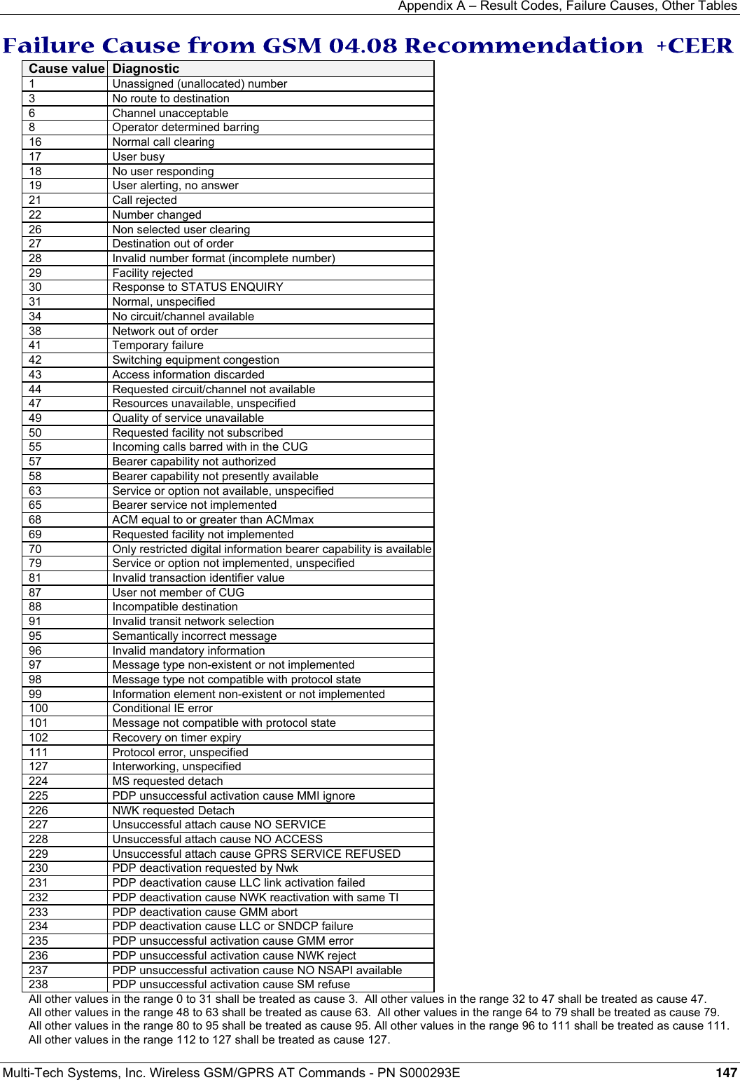
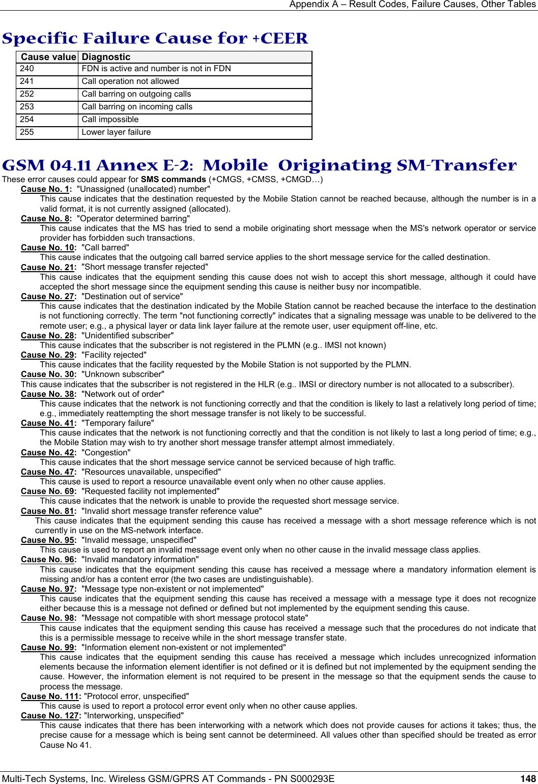
![Appendix A – Result Codes, Failure Causes, Other Tables Multi-Tech Systems, Inc. Wireless GSM/GPRS AT Commands - PN S000293E 149 Unsolicited Result Codes Verbose Result Code Numeric (V0 set) Description +CALA: < time string>,<index> As verbose Alarm notification +CBM: <length><pdu> (PDU) or +CBM:<sn>,<mid>,<dcs>,<page>,<pages>… (Text mode) As verbose Cell Broadcast Message directly displayed +CBMI: “BM”,<index> As verbose Cell Broadcast Message stored in mem at location <index> +CCCM: <ccm> As verbose Current Call Meter value +CCED: <values> As verbose (specific) Cell Environment Description indication +CCWA:<number>,<type>, <class> [,<alpha>] As verbose Call Waiting number +CDS: <fo>, <mr>… (text mode) or +CDS: <length>,… (PDU) As verbose SMS status report after sending a SMS +CDSI: <mem>,<index> As verbose Incoming SMS Status Report after sending a SMS, stored in <mem> (“SR”) at location <index> +CKEV: <keynb> As verbose Key press or release +CLIP: <number>, <type> [,,,<alpha>] As verbose Incoming Call Presentation +CMT: <oa>… (text mode) or +CMT: [<alpha>,]… (PDU) As verbose Incoming message directly displayed +CMTI: <mem>,<index> As verbose Incoming message stored in <mem> (“SM”) at location <index> +CREG: <stat> [,<lac>,<ci>] As verbose Network registration indication +CRING: <type> As verbose Incoming call type (VOICE, FAX ...) +CSQ: <RxLev>,99 As verbose Automatic RxLev indication with AT+CCED=1,8 command +CSSU: <code2>[<number>,<type>] As verbose Supplementary service notification during a call +STIN: <ind> As verbose (specific) SIM ToolKit Indication +WIND: <IndicationNb> [,<CallId>] As verbose (specific) Specific unsolicited indication (SIM Insert/Remove, End of init, Reset, Alerting, Call creation/release) +WVMI: <LineId>,<Status> As verbose (specific) Voice Mail Indicator notification (cf. +CPHS command) +WDCI: <LineId>,<Status> As Verbose (specific) Diverted call indicator RING 2 Incoming call signal from network +CIEV As Verbose (specific) Indicator event reporting Final Result Codes Verbose Result Code Numeric (V0 set) Description +CME ERROR: <err> As verbose Error from GSM 07.05 commands +CMS ERROR: <err> As verbose Error from SMS commands (07.07) BUSY 7 Busy signal detected ERROR 4 Command not accepted NO ANSWER 8 Connection completion timeout NO CARRIER 3 Connection terminated OK 0 Acknowledges correct execution of a command line RING 2 Incoming call signal from network Intermediate Result Codes Verbose Result Code Numeric (V0 set) Description +COLP:<number>,<type> as verbose Outgoing Call Presentation +CR: <type> as verbose Outgoing Call report control +ILRR: <rate> as verbose Local TA-TE data rate CONNECT 300 10 Data connection at 300 bauds CONNECT 1200 11 Data connection at 1200 bauds CONNECT 1200/75 12 Data connection at 1200/75 bauds CONNECT 2400 13 Data connection at 2400 bauds CONNECT 4800 14 Data connection at 4800 bauds CONNECT 9600 15 Data connection at 9600 bauds CONNECT 14400 16 Data connection at 14400 bauds +CSSI: <code1>[,<index>] As verbose Supplementary service notification during a call setup](https://usermanual.wiki/Multi-Tech-Systems/92U07A31817/User-Guide-789840-Page-149.png)
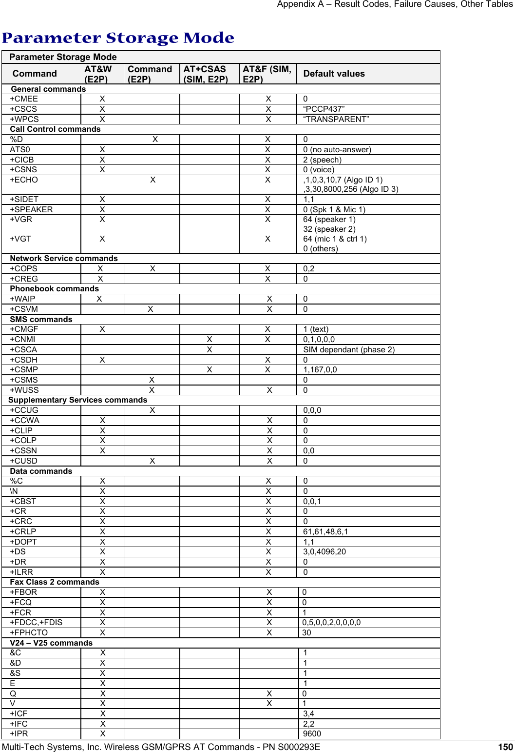
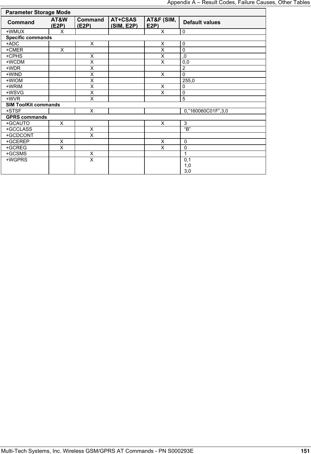
![Appendix A – Result Codes, Failure Causes, Other Tables Multi-Tech Systems, Inc. Wireless GSM/GPRS AT Commands - PN S000293E 152 GSM Sequences List In accordance with GSM Technical Specification 02.30, the product supports the following GSM sequences, which can be used through the ATD and the +CKPD commands. Security **04*OLDPIN*NEWPIN*NEWPIN# Change PIN code **042*OLDPIN2*NEWPIN2*NEWPIN2# Change PIN2 code **05*PUK*NEWPIN*NEWPIN# Unlock PIN code **052*PUK2*NEWPIN2*NEWPIN2# Unlock PIN2 code *#06# Show the IMEI number Call Forwarding *SC# or *SC**bs# Activate **SC*PhoneNumber# or Register and activate **SC*PhoneNumber*BS# or **SC*PhoneNumber*[BS]*T# or *SC*PhoneNumber# or *SC*PhoneNumber*BS# or *SC*PhoneNumber*[BS]*T# *#SC# or *#SC**BS# Check status #SC# or #SC**BS# Deactivate ##SC# or ##SC**BS# Unregistered and deactivate The Service codes (SC) are: 002 all call forwarding 004 all conditional call forwarding 21 call forwarding unconditional 61 call forwarding on no answer 62 call forwarding on not reachable 67 call busy The Network service codes (BS) are: No code All tele and bearer services 10 All teleservices 11 Telephony 12 All data teleservices 13 Fax services 16 Short Message Services 17 Voice Group Call Service 18 Voice Broadcast Service 19 All teleservices except SMS 20 All bearer services 21 All asynchronous services 22 All synchronous services 24 All data circuit synchronous 25 All data circuit asynchronous 26 All dedicated packet access 27 All dedicated PAD access The no reply condition timer (T) is only used for SC = 002, 004 or 61.](https://usermanual.wiki/Multi-Tech-Systems/92U07A31817/User-Guide-789840-Page-152.png)
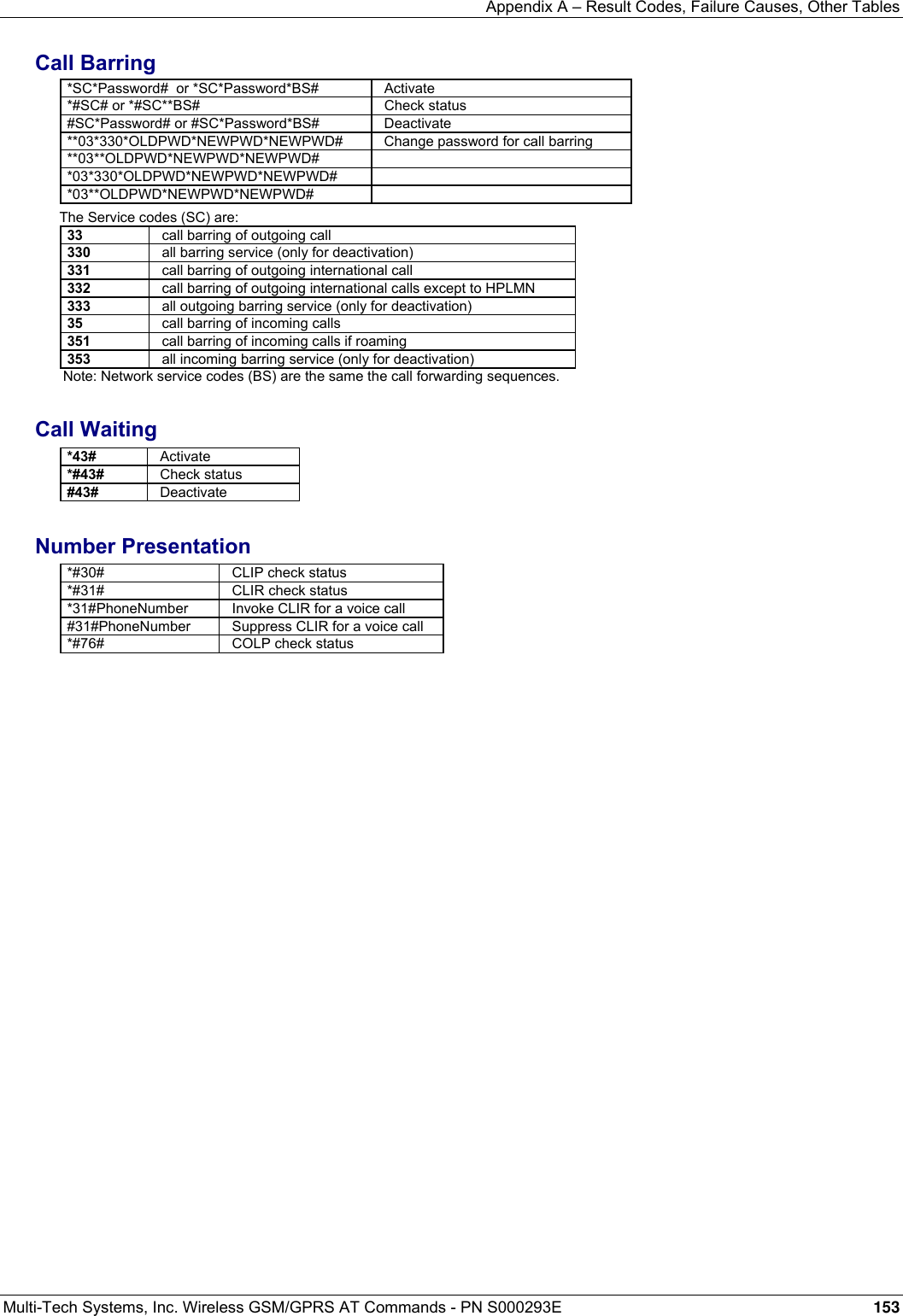
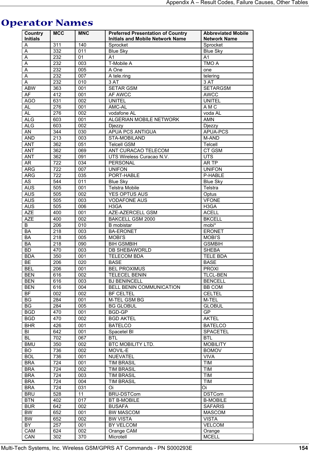
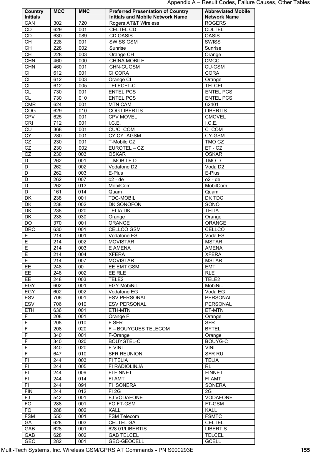
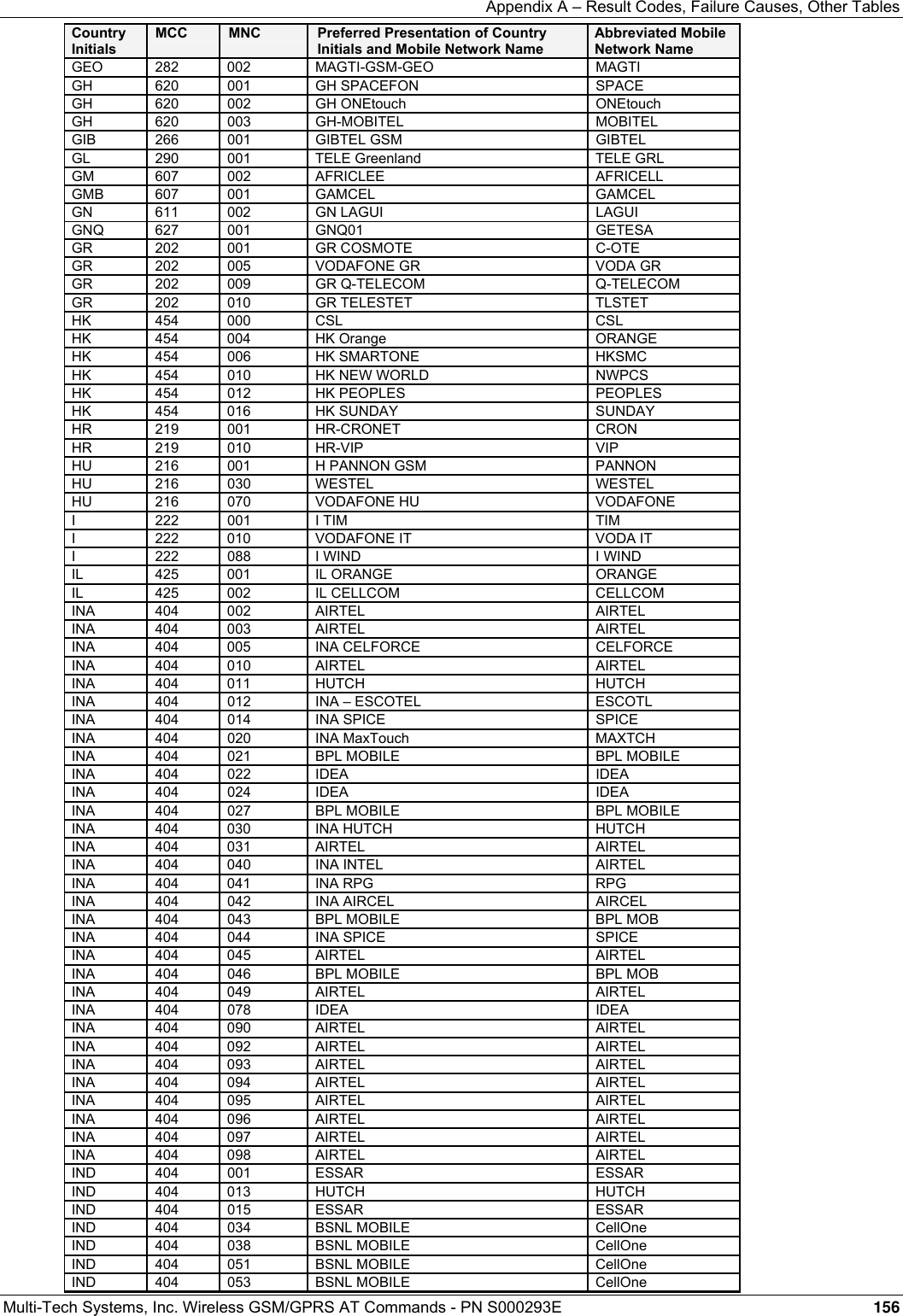
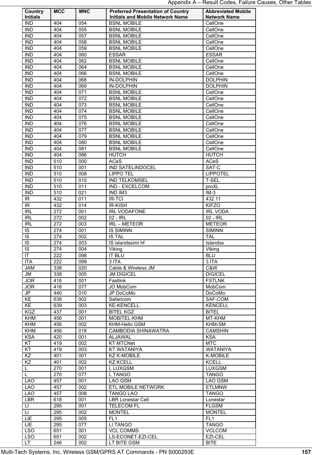
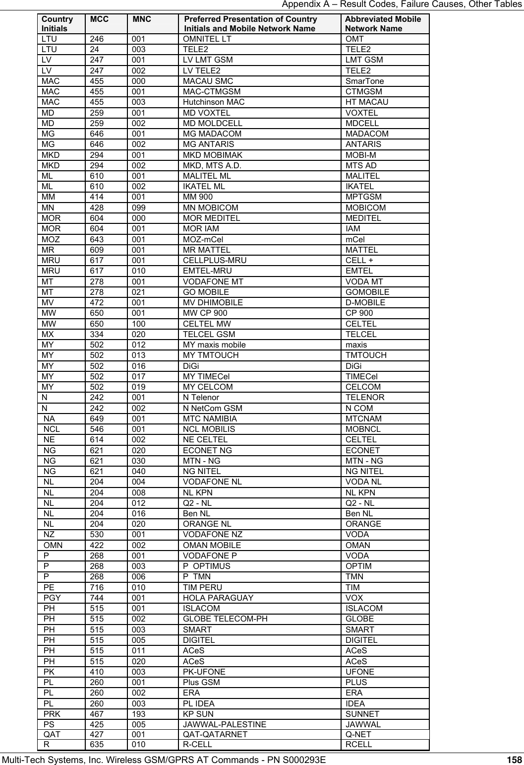
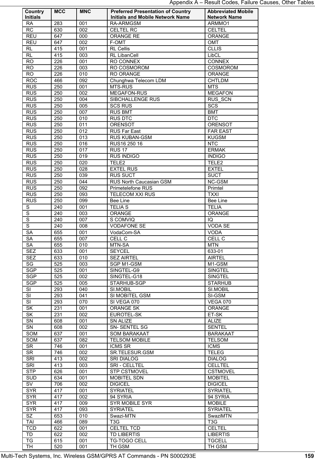
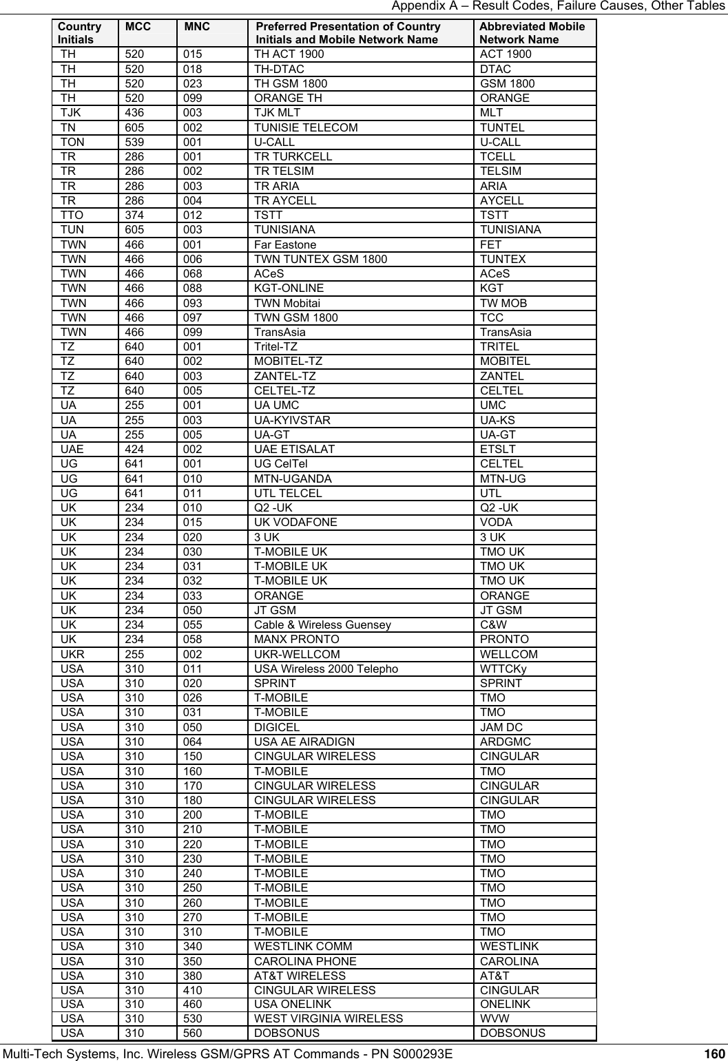
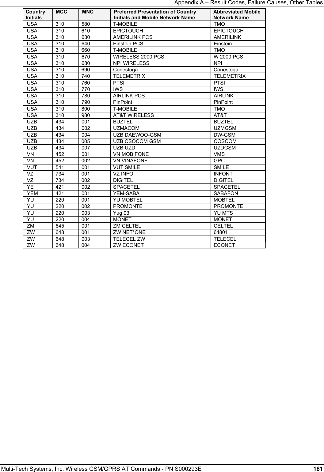
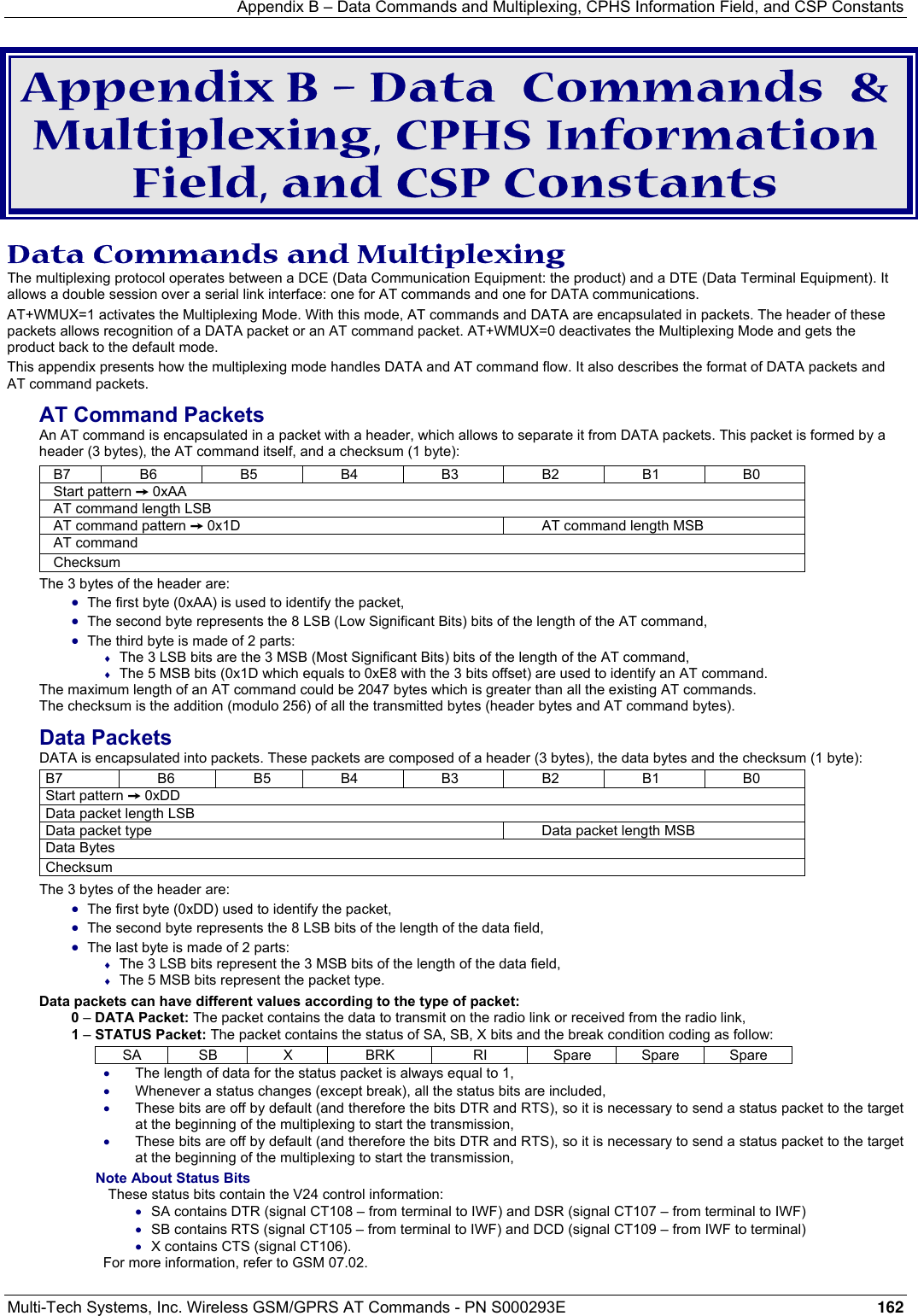
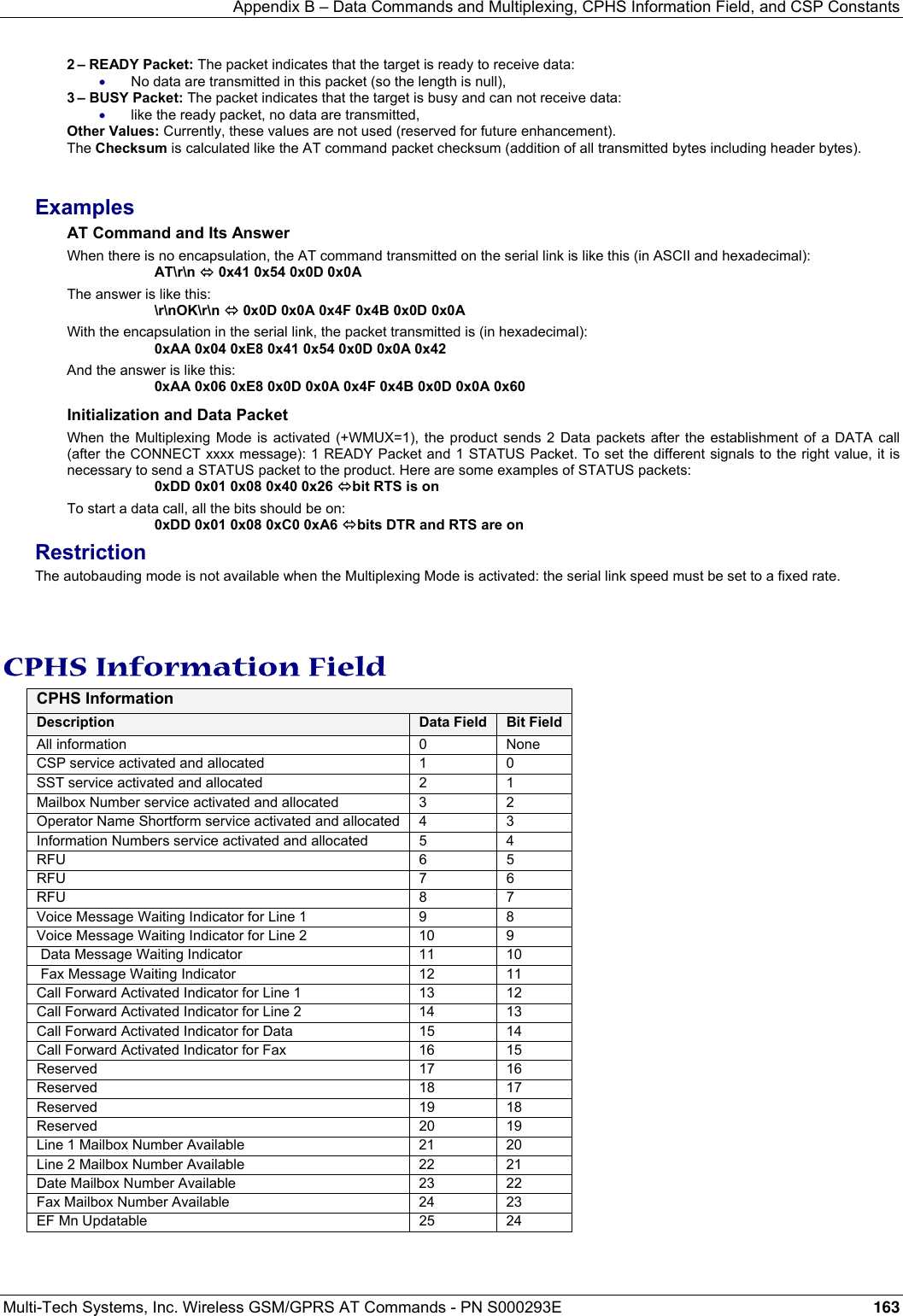
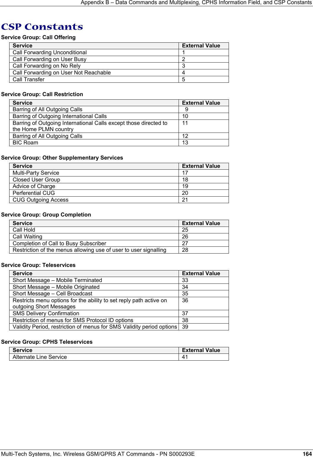
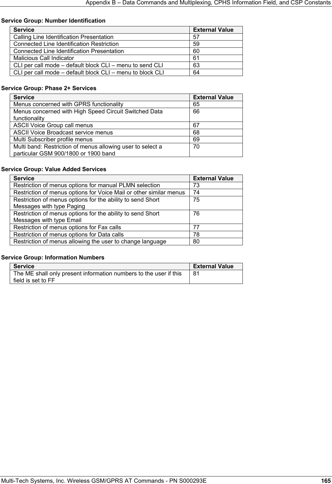
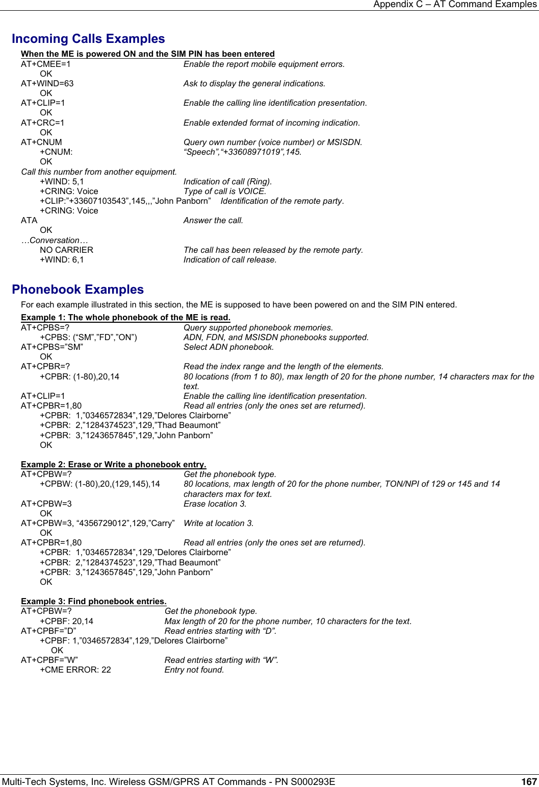
![Appendix C – AT Command Examples Multi-Tech Systems, Inc. Wireless GSM/GPRS AT Commands - PN S000293E 168 Examples of Short Messages Example 1: Send a short message. AT+CNMI=0,1,1,1,0 SMS-DELIVERs are directly stored. SMS-STATUS-REPORTs are displayed. OK AT+CSMP=17,169,0,0 SMS-SUBMIT message with a validity period (one day). OK AT+CMGF=1 ” ” Text mode to send a Short Message. OK AT+CSCA=”+33608080706” Set Service Center Address to +33608080706. OK AT+CMGS=0601290800 Send a SMS-SUBMIT to mobile phone. Product sends a 4-character sequence: 0x0D 0x0A 0x3E 0x20. This is the first text line Edit first line and press carriage return (<CR>, 0x0D). This is the last text line Edit last line and send message by pressing <ctrl-Z> (0x1A). +CMGS: 5 Success: message reference 5 is returned from the SMS Service Center. +CDS: 2,5,”0601290800”,129,”99/05/01 14:15:10+04. ” ” ” ” Success: report of successful message delivery received. Example 1: Read a short message. AT+CMGF=1 Text mode to read Short Messages. AT+CMGL=”ALL” List all stored messages. +CMGL: 1,”REC READ”,”+336290918”,,”99/05/01 14:15:10+04” I will be late. This is the first message. +CMGL: 2,”REC UNREAD”,”+336290918”,,”99/05/01 14:19:44+04” Traffic jam on Broadway. This is the second message. OK AT+CMGR=1 ” ” Read the first message. +CMGR: ”REC READ”,”+336290918”,,”99/05/01 14:19:44+04” OK Fax Class 2 Examples The normal characters are generated DTE. The bold characters are modem generated. Example 1: Send a fax Class 2. AT+FCLASS=2 Select fax class 2. OK AT+FLID="LocalFax" OK ATD0601234567 Call establishment. +FCON Connection OK. [+FCSI:"RemoteFax"] +FDIS:0,3,0,2,0,0,0,0 OK AT+FDT Beginning of the data transfer. +FDCS:0,3,0,2,0,0,0,0 CONNECT <0x11h> Send carrier. First page data terminated by <0x10h><0x03h>. OK Page transmitted. AT+FET=0 Send another page. +FPTS:1 First page acquitted. OK AT+FDT CONNECT <0x11h> Send carrier. Second page data terminated by <0x10h><0x03h>. OK Page transmitted. AT+FET=2 No more pages. +FPTS:1 First page acknowledged. +FHNG:0 Normal end of connection. OK](https://usermanual.wiki/Multi-Tech-Systems/92U07A31817/User-Guide-789840-Page-168.png)
![Appendix C – AT Command Examples Multi-Tech Systems, Inc. Wireless GSM/GPRS AT Commands - PN S000293E 169 Example 2: Receive a fax Class 2. AT+FCR=1 OK AT+FLID="LocalFax" OK RING Incoming call. ATA Answer. +FCON Connection OK. [+FTSI:"RemoteFax"] +FDCS:0,3,0,2,0,0,0,0 OK AT+FDR +FCFR +FDCS:0,3,0,2,0,0,0,0 CONNECT <0x12h> Receive page carrier. First page data terminated by <0x10h><0x03h> OK Page received. +FPTS:1 First page acknowledged. +FET:0 To receive another page. OK AT+FDR +FDCS:0,3,0,2,0,0,0,0 CONNECT <0x12h> Receive page carrier. Second page data terminated by <0x10h><0x03h> OK Page received +FPTS:1 Second page acknowledged. +FET:2 No more page to receive. OK AT+FDR +FHNG:0 Normal end of connection. OK](https://usermanual.wiki/Multi-Tech-Systems/92U07A31817/User-Guide-789840-Page-169.png)