Multi Tech Systems 92U07A31817 GSM/GPRS Modem Module User Manual
Multi Tech Systems Inc GSM/GPRS Modem Module
User Manual

Wireless GSM/GPRS
Modems
MultiModem GPRS (MTCBA-G)
ModemModule GPRS (MTMMC-G)
SocketModem GPRS (MTSMC-G)
AT Commands
Fax Commands
V.24 and V.25 Commands
SIM Application Toolkit Commands
Reference Guide

Copyright and Technical Support
Multi-Tech Systems, Inc. Wireless GSM/GPRS AT Commands - PN S000293E 2
AT Commands for Wireless GSM/GPRS Modems
Reference Guide
Products: MTCBA-G-xx, MTMMC-G-xx, and MTSMC-G-xx
PN S000293E, Revision E
Copyright
This publication may not be reproduced, in whole or in part, without prior expressed written permission from Multi-Tech
Systems, Inc. All rights reserved. Copyright © 2003-2005, by Multi-Tech Systems, Inc.
Multi-Tech Systems, Inc. makes no representations or warranties with respect to the contents hereof and specifically
disclaims any implied warranties of merchantability or fitness for any particular purpose. Furthermore, Multi-Tech
Systems, Inc. reserves the right to revise this publication and to make changes from time to time in the content hereof
without obligation of Multi-Tech Systems, Inc. to notify any person or organization of such revisions or changes.
Revisions
Revision Level Date Description
A 07/15/03 Initial release.
B 03/08/04 Added Values to each command. Added new commands.
C 09/28/04 Changed data/fax call to ATD<nb>; and voice call to ATD<nb>
Changed Autobauding is supported (operating from 2400 to 115200)
D 08/04/05 Added “Length of Phone Numbers” section to Chapter 3. Changed maximum length of
phone numbers to 60 digits. Added <mode> to +CMGF values. Added new command,
+CMMS. Removed values 2 and 4 from \N. Increased I/O ports to ten in the index value
of +WIOR and +WIOW. Added more text to +WRIM. Removed one note from +CGCONT.
Changed the font size from 10 point to 9 point; this brought the manual under 200 pages.
E 01/23/06 Added and to products listed on the cover.
Trademarks
MultiModem, SocketModem, and the Multi-Tech logo are registered trademarks of Multi-Tech Systems, Inc.
ModemModule is a trademark of Multi-Tech Systems, Inc.
World Headquarters
Multi-Tech Systems, Inc.
2205 Woodale Drive
Mounds View, Minnesota 55112
Phone: 763-785-3500 or 800-328-9717
Fax: 763-785-9874
Technical Support
Country By Email By Phone
France: support@multitech.fr (33) 1-64 61 09 81
India: support@multitechindia.com 91 (124) 6340778
U.K.: support@multitech.co.uk (44) 118 959 7774
U.S. and Canada: support@multitech.com (800) 972-2439
Rest of the World: support@multitech.com (763) 717-5863
Internet Address: http://www.multitech.com

Table of Contents
Multi-Tech Systems, Inc. Wireless GSM/GPRS AT Commands - PN S000293E 3
Contents
Chapter 1 – Introduction................................................................................................................................................9
Scope of This Document ............................................................................................................................................9
Related Documents....................................................................................................................................................9
Definitions ..................................................................................................................................................................9
Chapter 2 – AT Command Features ...........................................................................................................................10
Line Settings ............................................................................................................................................................10
Command Line.........................................................................................................................................................10
Information Responses and Result Codes ...............................................................................................................10
Chapter 3 – General Behaviors...................................................................................................................................11
SIM Card Insertion and Removal Procedures ..........................................................................................................11
Background Initialization ..........................................................................................................................................11
About the Length of Phone Numbers .......................................................................................................................11
Chapter 4 – General AT Commands ...........................................................................................................................12
Manufacturer Identification +CGMI.........................................................................................................................12
Request Model Identification +CGMM....................................................................................................................12
Request Revision Identification +CGMR ................................................................................................................12
Product Serial Number +CGSN..............................................................................................................................12
Select TE Character Set +CSCS............................................................................................................................13
Phonebook Character Set +WPCS ........................................................................................................................13
Request IMSI +CIMI...............................................................................................................................................13
Card Identification +CCID.......................................................................................................................................14
Capabilities List +GCAP.........................................................................................................................................14
Repeat Last Command A/ .......................................................................................................................................14
Power Off +CPOF ...................................................................................................................................................14
Set Phone Functionality +CFUN ............................................................................................................................15
Phone Activity Status +CPAS.................................................................................................................................15
Report Mobile Equipment Errors +CMEE...............................................................................................................15
Keypad Control +CKPD .........................................................................................................................................16
Clock Management +CCLK....................................................................................................................................16
Alarm Management +CALA....................................................................................................................................16
Chapter 5 – AT Call Control Commands....................................................................................................................17
Dial Command D....................................................................................................................................................17
Hang-Up command H.............................................................................................................................................18
Answer a Call A......................................................................................................................................................18
Remote Disconnection .............................................................................................................................................18
Extended Error Report +CEER ..............................................................................................................................19
DTMF Signals +VTD, +VTS ...................................................................................................................................19
Redial Last Telephone Number DL ........................................................................................................................19
Automatic Dialing with DTR %D.............................................................................................................................20
Automatic Answer S0.............................................................................................................................................20
Incoming Call Bearer +CICB ..................................................................................................................................20
Single Numbering Scheme +CSNS........................................................................................................................21
Gain Control +VGR, +VGT.....................................................................................................................................21
Microphone Mute Control +CMUT..........................................................................................................................22
Speaker & Microphone Selection +SPEAKER .......................................................................................................22
Echo Cancellation +ECHO .....................................................................................................................................23
SideTone Modification +SIDET ..............................................................................................................................24
Initialize Voice Parameters +VIP ............................................................................................................................25

Table of Contents
Multi-Tech Systems, Inc. Wireless GSM/GPRS AT Commands - PN S000293E 4
Chapter 6 – Network Service Commands ..................................................................................................................26
Signal Quality +CSQ ...............................................................................................................................................26
Operator Selection +COPS ....................................................................................................................................26
Network Registration +CREG.................................................................................................................................28
Read Operator Name +WOPN................................................................................................................................28
Selection of Preferred PLMN List +CPLS...............................................................................................................29
Preferred Operator List +CPOL..............................................................................................................................29
Read Operator Name +COPN................................................................................................................................31
Chapter 7 – Security Commands................................................................................................................................32
Enter PIN +CPIN ....................................................................................................................................................32
Enter PIN2 +CPIN2 ................................................................................................................................................34
PIN Remaining Attempt Number +CPINC..............................................................................................................34
Facility Lock +CLCK...............................................................................................................................................35
Change Password +CPWD ....................................................................................................................................36
Chapter 8 – Phonebook Commands ..........................................................................................................................37
Select Phonebook Memory Storage +CPBS...........................................................................................................37
Read Phonebook Entries +CPBR ..........................................................................................................................37
Find Phonebook Entries +CPBF ............................................................................................................................38
Write Phonebook Entry +CPBW.............................................................................................................................39
Phonebook Phone Search +CPBP.........................................................................................................................40
Move Action in Phonebook +CPBN........................................................................................................................40
Subscriber Number +CNUM...................................................................................................................................41
Avoid Phonebook Initialization +WAIP ...................................................................................................................42
Delete Calls Phonebook +WDCP...........................................................................................................................42
Set Voice Mail Number +CSVM ..............................................................................................................................42
Chapter 9 – Short Messages .......................................................................................................................................43
Parameters Definition...............................................................................................................................................43
Select Message Service +CSMS ............................................................................................................................44
New Message Acknowledgement +CNMA.............................................................................................................44
Preferred Message Storage +CPMS......................................................................................................................45
Preferred Message Format +CMGF.......................................................................................................................46
Save Settings +CSAS ............................................................................................................................................46
Restore Settings +CRES........................................................................................................................................46
Show Text Mode Parameters +CSDH.....................................................................................................................47
New Message Indication +CNMI ............................................................................................................................48
Read Message +CMGR .........................................................................................................................................49
List Message +CMGL.............................................................................................................................................50
Send Message +CMGS .........................................................................................................................................51
Write Message to Memory +CMGW.......................................................................................................................51
Send Message from Storage +CMSS ....................................................................................................................52
Set Text Mode Parameters +CSMP ........................................................................................................................52
Delete Message +CMGD .......................................................................................................................................53
Service Center Address +CSCA ............................................................................................................................53
Select Cell Broadcast Message Types +CSCB......................................................................................................54
Cell Broadcast Message Identifiers +WCBM..........................................................................................................54
Message Status Modification +WMSC ...................................................................................................................55
Message Overwriting +WMGO...............................................................................................................................55
Unchange SMS Status +WUSS .............................................................................................................................56
More Messages to Send +CMMS ..........................................................................................................................56
Chapter 10 – Supplementary Services Commands ..................................................................................................57
Call Forwarding +CCFC ..........................................................................................................................................57

Table of Contents
Multi-Tech Systems, Inc. Wireless GSM/GPRS AT Commands - PN S000293E 5
Call Barring +CLCK................................................................................................................................................58
Modify SS Password +CPWD ................................................................................................................................58
Call Waiting +CCWA ..............................................................................................................................................59
Calling Line Identification Restriction +CLIR ..........................................................................................................59
Calling Line Identification Presentation +CLIP .......................................................................................................60
Connected Line Identification Presentation +COLP ...............................................................................................60
Advice of Charge +CAOC ......................................................................................................................................61
Accumulated Call Meter +CACM............................................................................................................................61
Accumulated Call Meter Maximum +CAMM...........................................................................................................62
Price Per Unit and Currency Table +CPUC............................................................................................................62
Call Related Supplementary Services +CHLD .......................................................................................................62
List Current Calls +CLCC.......................................................................................................................................63
Supplementary Service Notifications +CSSN.........................................................................................................64
Unstructured Supplementary Service Data +CUSD ...............................................................................................65
Closed User Group +CCUG ....................................................................................................................................65
Chapter 11 – Data Commands ....................................................................................................................................66
Using AT Commands During a Data Connection .....................................................................................................66
Bearer Type Selection +CBST ...............................................................................................................................67
Select Mode +FCLASS ..........................................................................................................................................68
Service Reporting Control +CR ...............................................................................................................................68
Cellular Result Codes +CRC..................................................................................................................................69
DTE-DCE Local Rate Reporting +ILRR..................................................................................................................69
Radio Link Protocol Parameters +CRLP ................................................................................................................70
Other Radio Link Parameters +DOPT.....................................................................................................................70
Select Data Compression %C.................................................................................................................................70
V42bis Data Compression +DS..............................................................................................................................71
V42bis Data Compression Report +DR..................................................................................................................71
Select Data Error Correcting Mode \N....................................................................................................................72
Chapter 12 – Fax Commands......................................................................................................................................73
Transmit Speed +FTM............................................................................................................................................73
Receive Speed +FRM ............................................................................................................................................73
HDLC Transmit Speed +FTH .................................................................................................................................73
HDLC Receive Speed +FRH..................................................................................................................................74
Stop Transmission and Wait +FTS.........................................................................................................................74
Receive Silence +FRS ...........................................................................................................................................74
Setting Up the PC Fax Application: ..........................................................................................................................74
Chapter 13 – Fax Class 2 Commands ........................................................................................................................75
Transmit Data +FDT...............................................................................................................................................75
Receive Data +FDR ................................................................................................................................................75
Transmit Page Punctuation +FET ...........................................................................................................................75
Page Transfer Status Parameters +FPTS...............................................................................................................75
Terminate Session +FK..........................................................................................................................................76
Page Transfer Bit Order +FBOR ............................................................................................................................76
Buffer Size Report +FBUF......................................................................................................................................76
Copy Quality Checking +FCQ .................................................................................................................................76
Capability to Receive +FCR ....................................................................................................................................76
Current Sessions Parameters +FDIS ......................................................................................................................77
DCE Capabilities Parameters +FDCC....................................................................................................................78
Local ID String +FLID.............................................................................................................................................78
Page Transfer Timeout Parameter +FPHCTO ........................................................................................................78
Fax Class 2 Indication Messages.............................................................................................................................79

Table of Contents
Multi-Tech Systems, Inc. Wireless GSM/GPRS AT Commands - PN S000293E 6
Chapter 14 – V.24 and V.25 Commands .....................................................................................................................80
Fixed DTE Rate +IPR.............................................................................................................................................80
DTE-DCE Character Framing +ICF........................................................................................................................81
DTE-DCE Local Flow Control +IFC........................................................................................................................82
Set DCD Signal &C ................................................................................................................................................82
Set DTR Signal &D.................................................................................................................................................82
Set DSR Signal &S.................................................................................................................................................83
Back to Online Mode O ...........................................................................................................................................83
Result Code Suppression Q...................................................................................................................................83
DCE Response Format V.......................................................................................................................................83
Default Configuration Z ..........................................................................................................................................83
Save Configuration &W ...........................................................................................................................................84
Auto-Tests &T ........................................................................................................................................................84
Echo E....................................................................................................................................................................84
Restore Factory Settings &F ..................................................................................................................................84
Display Configuration &V .......................................................................................................................................85
Request Identification Information I ........................................................................................................................85
Multiplexing Mode +WMUX .....................................................................................................................................86
Chapter 15 – Specific AT Commands ........................................................................................................................87
Cell Environment Description +CCED....................................................................................................................87
General Indications +WIND....................................................................................................................................89
Analog Digital Converter Measurements +ADC ......................................................................................................90
Mobile Equipment Event Reporting +CMER ..........................................................................................................91
Indicator Control +CIND ...........................................................................................................................................92
Mobile Equipment Control Mode +CMEC................................................................................................................93
Read Language Preference +WLPR......................................................................................................................93
Write Language Preference +WLPW .....................................................................................................................94
Read GPIO Value +WIOR.......................................................................................................................................94
Write GPIO Value +WIOW .....................................................................................................................................94
Input/Output Management +WIOM ........................................................................................................................95
Abort Command +WAC..........................................................................................................................................95
Play Tone +WTONE...............................................................................................................................................96
Play DTMF Tone +WDTMF....................................................................................................................................97
Downloading +WDWL ............................................................................................................................................97
Voice Rate +WVR ..................................................................................................................................................98
Data Rate +WDR ...................................................................................................................................................98
Select Voice Gain +WSVG.....................................................................................................................................99
Status Request +WSTR .........................................................................................................................................99
Scan +WSCAN.......................................................................................................................................................99
Ring Indicator Mode +WRIM ................................................................................................................................100
32kHz Power Down Mode +W32K .......................................................................................................................101
Change Default Melody +WCDM .........................................................................................................................101
Custom Character Set +WCCS............................................................................................................................102
Lock +WLCK ........................................................................................................................................................103
CPHS Command +CPHS.....................................................................................................................................104
Unsolicited Result: Voice Mail Indicator +WVMI...................................................................................................106
Unsolicited Result: Diverted Call Indicator +WDCI...............................................................................................106
Network Operator Name +WNON ........................................................................................................................107
CPHS Information +WCPI....................................................................................................................................107
Customer Service Profile +WCSP.........................................................................................................................108
Customer Storage Mirror +WMIR.........................................................................................................................108

Table of Contents
Multi-Tech Systems, Inc. Wireless GSM/GPRS AT Commands - PN S000293E 7
Change Default Player +WCDP ............................................................................................................................108
CPHS Mail Box Number +WMBN ........................................................................................................................109
Alternate Line Service +WALS.............................................................................................................................110
Open AT Control Command +WOPEN ................................................................................................................110
Reset +WRST ......................................................................................................................................................111
Set Standard Tone +WSST..................................................................................................................................112
Hang-up +WATH..................................................................................................................................................112
Chapter 16 – SIM ToolKit...........................................................................................................................................113
Overview of SIM Application ToolKit ......................................................................................................................113
Messages Exchanged During a SIM ToolKit Operation .........................................................................................114
SIM Toolkit Commands ..........................................................................................................................................115
SIM ToolKit Set Facilities +STSF .........................................................................................................................115
SIM ToolKit Indication +STIN ...............................................................................................................................117
SIM ToolKit Get Information +STGI......................................................................................................................118
Unsolicited Result: SIM ToolKit Control Response +STCR..................................................................................121
SIM ToolKit Give Response +STGR ....................................................................................................................121
Chapter 17 – GPRS commands ................................................................................................................................124
Define PDP Context +CGDCONT ........................................................................................................................124
Quality of Service Profile Requested +CGQREQ..................................................................................................126
Quality of Service Profile Minimum Acceptable +CGQMIN ..................................................................................128
GPRS Attach or Detach +CGATT ........................................................................................................................129
PDP Context Activate or Deactivate +CGACT .....................................................................................................130
Enter Data State +CGDATA.................................................................................................................................131
GPRS Mobile Station Class +CGCLASS .............................................................................................................132
Select Service for MO SMS Messages +CGSMS ................................................................................................133
GPRS Event Reporting +CGEREP ......................................................................................................................134
GPRS Network Registration Status +CGREG......................................................................................................135
Request GPRS IP Service D................................................................................................................................135
Network Requested PDP Context Activation..........................................................................................................136
Automatic Response to a Network Request for PDP Context Activation +CGAUTO ...........................................137
Manual Response to a Network Request for PDP Context Activation +CGANS..................................................138
Show PDP Address +CGPADDR.........................................................................................................................139
Cellular Result Codes +CRC................................................................................................................................139
Service Reporting Control +CR ............................................................................................................................140
Extended Error Report +CEER ............................................................................................................................140
GPRS Parameters Customization +WGPRS .......................................................................................................141
Full GPRS AT Command Examples.......................................................................................................................142
GPRS-Related Errors +CME ERROR..................................................................................................................143
Specific GPRS Failure Cause for +CEER ..............................................................................................................143
Chapter 18 – Other AT Commands...........................................................................................................................144
V.25ter Recommendation.......................................................................................................................................144
GSM 07.05 Recommendation ................................................................................................................................144
GSM 07.07 Recommendation ...............................................................................................................................144
Appendix A – Result Codes, Failure Causes, Other Tables ...................................................................................145
ME Error Result Code: +CME ERROR: <error>...................................................................................................145
Message Service Failure Result Code +CMS ERROR: <er>................................................................................146
Specific Error Result Codes ...................................................................................................................................146
Failure Cause from GSM 04.08 Recommendation +CEER...................................................................................147
Specific Failure Cause for +CEER .........................................................................................................................148
GSM 04.11 Annex E-2: Mobile Originating SM-Transfer......................................................................................148
Unsolicited Result Codes .......................................................................................................................................149

Table of Contents
Multi-Tech Systems, Inc. Wireless GSM/GPRS AT Commands - PN S000293E 8
Final Result Codes .................................................................................................................................................149
Intermediate Result Codes.....................................................................................................................................149
Parameter Storage Mode .......................................................................................................................................150
GSM Sequences List..............................................................................................................................................152
Operator Names.....................................................................................................................................................154
Appendix B – Data Commands & Multiplexing, CPHS Information Field, and CSP Constants ........................162
Data Commands and Multiplexing..........................................................................................................................162
CPHS Information Field..........................................................................................................................................163
CSP Constants.......................................................................................................................................................164
Appendix C - AT Command Examples.....................................................................................................................166
Examples ...............................................................................................................................................................166
Appendix D - ME SIM ToolKit Support .....................................................................................................................170
Appendix E – Structure of the Terminal Profile.......................................................................................................171
Appendix F – Command Type and Next Action Indicator .....................................................................................173
Appendix G – Coding of Alpha fields in the SIM for UCS2.....................................................................................174
Appendix H – Specification of Power Down Control via RS232 ............................................................................175
Appendix I – Conditions for Command Execution and SIM Dependence.............................................................176
General Commands ...............................................................................................................................................176
Call Control Commands .........................................................................................................................................176
Network Service Commands..................................................................................................................................176
Security Commands ...............................................................................................................................................177
Phonebook Commands..........................................................................................................................................177
Short Messages Commands ..................................................................................................................................177
Supplementary Services Commands .....................................................................................................................177
Data Commands ....................................................................................................................................................178
Fax Commands......................................................................................................................................................178
Class 2 Commands ................................................................................................................................................178
V24-V25 Commands ..............................................................................................................................................178
Specific AT Commands..........................................................................................................................................179
SIM ToolKit Commands .........................................................................................................................................179
Index ...........................................................................................................................................................................180

Chapter 1 – Introduction
Multi-Tech Systems, Inc. Wireless GSM/GPRS AT Commands - PN S000293E 9
Chapter 1 – Introduction
Scope of This Document
This document describes the AT-command based messages exchanged between an application and the Multi-Tech Systems,
Inc. products in order to manage GSM-related events or services.
Related Documents
This interface specification is based on the following recommendations:
[1] ETSI GSM 07.05: Digital cellular telecommunications system (Phase 2);
Use of DTE-DCE interface for Short Message Service (SMS) and Cell Broadcast Service (CBS)
[2] ETSI GSM 07.07: Digital cellular telecommunications system (Phase 2);
AT command set for GSM Mobile Equipment (ME)
[3] ITU-T Recommendation V.25 ter: Serial asynchronous automatic dialing and control
[4] ETSI GSM 03.40: Digital cellular telecommunications system (Phase 2);
Technical implementation of the Short Message Service (SMS) Point-to-Point (PP)
[5] ETSI GSM 03.38: Digital cellular telecommunications system (Phase 2);
Alphabets and language-specific information
[6] ETSI GSM 04.80: Digital cellular telecommunications system (Phase 2):
Mobile radio interface layer 3, Supplementary service specification, Formats and coding
Definitions
The words, “Mobile Station” (MS) or “Mobile Equipment” (ME) are used for mobile terminals supporting GSM services.
A call from a GSM mobile station to the PSTN is called a “mobile originated call” (MOC) or “outgoing call”, and a call from
a fixed network to a GSM mobile station is called a “mobile terminated call” (MTC) or “incoming call”.
In this document, the word “product” refers to any Multi-Tech product supporting the AT commands interface.

Chapter 2 – AT Command Features
Multi-Tech Systems, Inc. Wireless GSM/GPRS AT Commands - PN S000293E 10
Chapter 2 – AT Command
Features
Line Settings
A serial link handler is set with the following default values (factory settings): autobaud, 8 bits data, 1 stop bit, no parity,
RTS/CTS flow control. Please use the +IPR, +IFC and +ICF commands to change these settings.
Command Line
Commands always start with AT (which means ATtention) and finish with a <CR> character.
Information Responses and Result Codes
Responses start and end with <CR><LF>, except for the ATV0 DCE response format and the ATQ1 (result code
suppression) commands.
• If command syntax is incorrect, an ERROR string is returned.
• If command syntax is correct but with some incorrect parameters, the +CME ERROR: <Err> or +CMS ERROR:
<SmsErr> strings are returned with different error codes.
• If the command line has been performed successfully, an OK string is returned.
In some cases, such as “AT+CPIN?” or (unsolicited) incoming events, the product does not return the OK string as a
response.
In the following examples <CR> and <CR><LF> are intentionally omitted.

Chapter 3 – General Behaviors
Multi-Tech Systems, Inc. Wireless GSM/GPRS AT Commands - PN S000293E 11
Chapter 3 – General Behaviors
SIM Card Insertion and Removal Procedures
SIM card Insertion and Removal procedures are supported. There are software functions relying on positive reading of the
hardware SIM detect pin. This pin state (open/closed) is permanently monitored.
When the SIM detect pin indicates that a card is present in the SIM connector, the product tries to set up a logical SIM
session. The logical SIM session will be set up or not depending on whether the detected card is a SIM Card or not. The
AT+CPIN? command delivers the following responses:
• If the SIM detect pin indicates “absent”, the response to AT+CPIN? is “+CME ERROR 10” (SIM not inserted).
• If the SIM detect pin indicates “present”, and the inserted Card is a SIM Card, the response to AT+CPIN? is
“+CPIN: xxx” depending on SIM PIN state.
• If the SIM detect pin indicates “present”, and the inserted Card is not a SIM Card, the response to AT+CPIN? is
CME ERROR 10.
• These last two states are not given immediately due to background initialization. Between the hardware SIM
detect pin indicating “present” and the previous results the AT+CPIN? sends “+CME ERROR: 515” (Please wait,
init in progress).
When the SIM detect pin indicates card absence, and if a SIM Card was previously inserted, an IMSI detach procedure is
performed, all user data is removed from the product (Phonebooks, SMS etc.). The product then switches to emergency
mode.
Background Initialization
After entering the PIN (Personal Identification Number), some SIM user data files are loaded into the product
(Phonebooks, SMS status, etc.). Please be aware that it might take some time to read a large phonebook.
The AT+CPIN? command response comes just after the PIN is checked. After this response user data is loaded (in
background). This means that some data may not be available just after PIN entry is confirmed by ’OK’. The reading of
phonebooks will then be refused by “+CME ERROR: 515” or “+CMS ERROR: 515” meaning, “Please wait, service is not
available, init in progress”.
This type of answer may be sent by the product at several points:
• When trying to execute another AT command before the previous one is completed (before response),
• When switching from ADN to FDN (or FDN to ADN) and trying to read the relevant phonebook immediately,
• When asking for +CPIN? status immediately after SIM insertion and before the product has determined if the
inserted card is a valid SIM Card.
About the Length of Phone Numbers
Phone numbers can be made of up to 60 digits. The first 20 digits are stored in the SIM in the phonebook file (EFADN,
EFFDN or EFLND) corresponding to the selected phonebook. The next digits are stored in other extension SIM files (EFEXT1
or EFEXT2).
Example:
Number of Digits Nb of Records in EFADN Nb of Records in EFEXT1
1 to 20 1 0
21 to 40 1 1
41 to 60 1 2
If there are no more free records in the EFEXT1, the behavior is:
• if the user tries to store an entry that exceeds 20 digits: +CME: 20
• if the user tries to dial an number that exceeds 20 digits: +CME: 20
Since the maximum length for the numbers in the ADN, FDN, and LND phonebooks is 60 digits:
• if the user tries to dial a number that exceeds 60 digits: +CME: 3
Before the user can perform a call, the number of free records in the EFEXT1 is checked for availability of free space to
store this number.
• If there are free records left, the call is setup.
• Otherwise, +CME: 20 error is returned (Memory Full).
See Recommendation 3GPP 11.11 for more details.

Chapter 4 – General AT Commands
Multi-Tech Systems, Inc. Wireless GSM/GPRS AT Commands - PN S000293E 12
Chapter 4 – General AT
Commands
Manufacturer Identification +CGMI
Description: Displays the manufacturer identification.
Values: No parameters
Syntax: AT+CGMI
Command Possible responses
AT+CGMI
Note: Get manufacturer identification
WAVECOM MODEM
OK
Note: Command valid, Wavecom modem
Request Model Identification +CGMM
Description: Displays the supported frequency bands. With multi-band products the response may be a combination
of different bands.
Values: No parameters
Syntax: AT+CGMM
Command Possible responses
AT+CGMM
Note: Get hardware version
MULTIBAND 900 E 1800
OK
Note: Multiband: GSM 900 MHz extended band and DCS
1800
AT+CGMM
Note: Get hardware version
MULTIBAND G850 1900
OK
Note: Multiband: GSM 850 and PCS
Request Revision Identification +CGMR
Description: Displays the revised software version.
Values: No parameters
Syntax: AT+CGMR
Command Possible responses
AT+CGMR
Note: Get software version
640b09gg.Q2406A 1266500 070403
17:06
OK
Note: Software release 6.40b, generated on the 4th
of July 2003
Product Serial Number +CGSN
Description: Allows the user application to get the IMEI (Interrnational Mobile Equipment Identity, 15-digit number) of
the product.
Values: No parameters
Syntax: AT+CGSN
Command Possible responses
AT+CGSN
Note: Get the IMEI
012345678901234
OK
Note: IMEI read from EEPROM
AT+CGSN
Note: Get the IMEI
+CME ERROR: 22
Note: IMEI not found in EEPROM

Chapter 4 – General AT Commands
Multi-Tech Systems, Inc. Wireless GSM/GPRS AT Commands - PN S000293E 13
Select TE Character Set +CSCS
Description: Informs the ME which character set is used by the TE. The ME can convert each character of entered
or displayed strings. This is used to send, read or write short messages. See also +WPCS for the
phonebooks’ character sets.
Values: <Character Set>
GSM GSM default alphabet.
PCCP437 PC character set code page 437.
CUSTOM User defined character set (cf. +WCCS command).
HEX Hexadecimal mode. No character set used; the user can read or write hexadecimal values.
Default: GSM alphabet
Syntax: AT+CSCS=<Character Set>
Command Possible responses
AT+CSCS=”GSM”
Note: GSM default alphabet
OK
Note: Command valid
AT+CSCS=”PCCP437”
Note: PC character set code
OK
Note: Command valid
AT+CSCS=?
Note: Get possible values
+CSCS: ("GSM","PCCP437","CUSTOM","HEX")
OK
Note: Possible values
Phonebook Character Set +WPCS
Description: Informs the ME which character set is used by the TE for the phonebooks. The ME can convert each
character of entered or displayed strings. This is used to read or write phonebook entries. See also
+CSCS for the short messages character sets.
Values: <Character Set>
TRANSPARENT Transparent mode. The strings are displayed and entered as they are stored in
SIM or in ME.
CUSTOM User defined character set (cf. +WCCS command).
HEX Hexadecimal mode. No character set used; the user can read or write
hexadecimal values.
Syntax: AT+WPCS=<Character Set>
Command Possible responses
AT+WPCS=”TRANSPARENT”
Note: Transparent mode
OK
Note: Command valid
AT+WPCS=”CUSTOM”
Note: Custom character set
OK
Note: Command valid
AT+WPCS=?
Note: Get possible values
+WPCS: ("TRANSPARENT","HEX","CUSTOM")
OK
Note: Possible values
Request IMSI +CIMI
Description: Reads and identifies the IMSI (International Mobile Subscriber Identity) of the SIM card. The PIN may
need to be entered before reading the IMSI.
Values: No parameters
Syntax: AT+CIMI
Command Possible responses
AT+CIMI
Note: Read the IMSI
208200120320598
OK
Note: IMSI value (15 digits), starting with MCC (3 digits) / MNC (2 digits, 3
for PCS 1900)

Chapter 4 – General AT Commands
Multi-Tech Systems, Inc. Wireless GSM/GPRS AT Commands - PN S000293E 14
Card Identification +CCID
Description: Orders the product to read the EF-CCID file on the SIM card.
Values: No parameters
Syntax: AT+CCID
Command Possible responses
AT+CCID
Note: Get card ID
+CCID: “123456789AB111213141”
Note: EF-CCID is present, hexadecimal format
AT+CCID?
Note: Get current value
+ CCID: “123456789AB111213141”
Note: Same result as +CCID
AT+CCID= ?
Note: Get possible value
OK
Note: No parameter but this command is valid
Note: If there is no EF-CCID file present on the SIM, the +CCID answer will not be sent, but the OK message will
be returned.
Capabilities List +GCAP
Description: Displays the complete list of capabilities.
Values: No parameters
Syntax: AT+GCAP
Command Possible responses
AT+GCAP
Note: Get capabilities list
+GCAP: +CGSM +FCLASS
OK
Note: Supports GSM and FAX commands
Repeat Last Command A/
Description: Repeats the previous command. Only the A/ command itself cannot be repeated.
Values: No parameters
Syntax: A/
Command Possible responses
A/
Note: Repeat last command
Power Off +CPOF
Description: Stops the GSM software stack as well as the hardware layer. The AT+CFUN=0 command is equivalent
to +CPOF.
Values: No parameters
Syntax: AT+CPOF
Command Possible responses
AT+CPOF
Note: Stop GSM stack
OK
Note: Command valid

Chapter 4 – General AT Commands
Multi-Tech Systems, Inc. Wireless GSM/GPRS AT Commands - PN S000293E 15
Set Phone Functionality +CFUN
Description: Selects the mobile station’s level of functionality. When the application wants to stop the product with a
power off, or if the application wants to force the product to execute an IMSI DETACH procedure, then it
must send: AT+CFUN=0 (equivalent to AT+CPOF). This command executes an IMSI DETACH and
makes a backup copy of some internal parameters in SIM and in EEPROM. The SIM card cannot then
be accessed. If the mobile equipment is not powered off by the application after this command has been
sent, a re-start command (AT+CFUN=1) will have to issued to restart the whole GSM registration
process. If the mobile equipment is turned off after this command, then a power on will automatically
restart the whole GSM process. The AT+CFUN=1 command restarts the entire GSM stack and GSM
functionality: a complete software reset is performed. All parameters are reset to their previous values if
AT&W was not used. If you write entries in the phonebook (+CPBW) and then reset the product directly
(AT+CFUN=1, with no previous AT+CFUN=0 command), some entries may not be written (the SIM task
does not have enough time to write entries in the SIM card). In addition, the OK response will be sent at
the last baud rate defined by the +IPR command. With the autobauding mode the response can be at a
different baud rate, it is therefore preferable to save the defined baud rate with AT&W before directly
sending the AT+CFUN=1 command.
Values: <functionality level>
0 Set minimum funtionality; IMSI detach procedure
1 Set the full functionality mode with a complete software reset
Syntax: AT+CFUN=<functionality level>
Command Possible responses
AT+CFUN?
Note: Ask for current functionality level
+CFUN: 1
OK
Note: Full functionality
AT+CFUN=0
Note: Set minimum functionality, IMSI detach procedure
OK
Note: Command valid
AT+CFUN=1
Note: Set the full functionality mode with a complete software reset
OK
Note: Command valid
Phone Activity Status +CPAS
Description: Returns the activity status of the mobile equipment.
Values: <pas>
0 ready (allow commands from TA/TE)
1 unavailable (does not allow commands)
2 unknown
3 ringing (ringer is active)
4 call in progress
5 asleep (low functionality)
Syntax: AT+CPAS
Command Possible responses
AT+CPAS
Note: Current activity status
+CPAS: <pas>
OK
Report Mobile Equipment Errors +CMEE
Description: Disables or enables the use of the “+CME ERROR: <xxx>” or “+CMS ERROR:<xxx>” result code
instead of simply “ERROR”. See Appendix A for +CME ERROR result codes description and +CMS
ERROR result codes.
Values: <error reporting flag>
0 Disable ME error reports; use only ERROR
1 Enable +CME ERROR: <xxx> or +CMS ERROR: <xxx>
Syntax: AT+CMEE=<error reporting flag>
Command Possible responses
AT+CMEE=0
Note: Disable ME error reports, use only ERROR
OK
AT+CMEE=1
Note: Enable +CME ERROR: <xxx> or
+CMS ERROR: <xxx>
OK

Chapter 4 – General AT Commands
Multi-Tech Systems, Inc. Wireless GSM/GPRS AT Commands - PN S000293E 16
Keypad Control +CKPD
Description: Emulates the ME keypad by sending each keystroke as a character in a <keys> string. The supported
GSM sequences are listed in the Appendix A.
If emulation fails, a +CME ERROR: <err> is returned. If emulation succeeds, the result depends on the
GSM sequence activated: <keys>: string of the following characters (0-9,*,#).
Note: In the case where the FDN phonebook is activated, the sequences concerning “call forwarding”
are allowed only if the entire sequence is written in the FDN.
Values: <keys>
Keyboard sequence; string of the following characters (0-9, *, #)
Syntax: AT+CKPD=<keys>
Command Possible responses
AT+CKPD=”*#21#”
Note: Check every call forwarding status
+CCFC: 0,7
AT+CKPD=”1234”
Note: Sequence not allowed
+CME ERROR 3
Clock Management +CCLK
Description: Sets or gets the current date and time of the ME real-time clock.
Values: <date and time string>
String format for date/time is “yy/MM/dd,hh:mm:ss”
Note: Valid years are 98 (for 1998) to 97 (for 2097). The seconds field is not mandatory. Default
date/time is “98/01/01,00:00:00” (January 1st, 1998 / midnight).
Syntax: AT+CCLK=<date and time string>
Command Possible responses
AT+CCLK=”00/06/09,17:33:00”
Note: set date to June 9th, 2000, and
time to 5:33pm
OK
Note: Date/Time stored
AT+CCLK=”00/13/13,12:00:00”
Note: Incorrect month entered
+CME ERROR 3
AT+CCLK?
Note: Get current date and time
+CCLK: “00/06/09,17:34:23”
OK
Note: current date is June 9th, 2000
current time is 5:34:23 pm
Alarm Management +CALA
Description: Sets the alarm date/time in the ME. The maximum number of alarms is 16.
Values: <date and time string> String format for alarms: “yy/MM/dd,hh:mm:ss” (see +CCLK)
Note: Seconds are taken into account.
<index> Offset in the alarm list, range 1 to 16
Syntax: AT+CALA=<date and time string> (set alarm)
AT+CALA=””,<index> (delete alarm)
Command Possible responses
AT+CALA=”00/06/09,07:30”
Note: set an alarm for June 9th, 2000 at 7:30 am
OK
Note: Alarm stored
AT+CALA=”99/03/05,13:00:00”
Note: set an alarm for March 5th, 1999 at 1:00 pm
+CME ERROR 3
Note: Invalid alarm (date/time expired)
AT+CALA?
Note: list all alarms
+CALA: “00/06/08,15:25:00”,0
+CALA: “00/06/09,07:30:00”,1
+CALA: “00/06/10,23:59:00”,2
Note: three alarms are set (index 0, 1, 2)
+CALA: “00/06/08,15:25:00”,0
Note: an alarm occurs (index 0)
AT+CALA=””,2
Note: delete alarm index 2
OK
Note: Alarm index 2 deleted
AT+CALA?
Note: list all alarms
+CALA: “00/06/09,07:30:00”,1
Note: Only one alarm (index 1)
Chapter 5 – AT Call Control Commands
Multi-Tech Systems, Inc. Wireless GSM/GPRS AT Commands - PN S000293E 17
Chapter 5 – AT Call Control
Commands
Dial Command D
Description: The ATD command sets a voice, data or fax call. As per GSM 02.30, the dial command also controls
supplementary services.
For a data or a fax call, the application sends the following ASCII string to the product (the bearer must
be previously selected with the +CBST command):
ATD<nb> where <nb> is the destination phone number;
For a voice call, the application sends the following ASCII string to the product: (the bearer may be
selected previously, if not a default bearer is used).
ATD<nb>; where <nb> is the destination phone number.
Please note that for an international number, the local international prefix does not need to be set
(usually 00) but does need to be replaced by the ‘+’ character.
Example: to set up a voice call to Multi-Tech offices from another country, the AT command is:
“ATD+17637853600;”
Note that some countries/regions may have specific numbering rules for their GSM handset numbering.
Values: <nb> Destination phone number
<I> Optional parameter <I> means “invocation” (restrict CLI presentation)
<i> Means “suppresssion” (allow CLI presentation)
<mem> Phonebook (one of SM, LD, MC, ME, RC, MT or SN). A default value can be selected by
+CPBS command.
<index> Call number at indicated offset from the phonebook selected by the +CPBS command.
<name> Call number corresponding to given name from the phonebook selected by the +CPBS
command.
The response to the ATD command is one of the following:
Verbose result code Numeric code
(with ATV0 set)
Description
OK 0 if the call succeeds, for voice call only
CONNECT <speed> 10,11,12,13,14,15 if the call succeeds, for data calls only, <speed> takes
the value negotiated by the product.
BUSY 7 If the called party is already in communication
NO ANSWER 8 If no hang up is detected after a fixed network time-out
NO CARRIER 3 Call setup failed or remote user release. Use the
AT+CEER command to know the failure cause
Direct Dialing from a Phonebook (stored in the SIM card) can be performed with the following commands:
ATD> <index>; to call <index> from the selected phonebook (by the +CPBS command)
ATD> “BILL”; to call “BILL” from the selected phonebook
ATD> mem <index> (mem is SM, LD, MC, ME, RC, MT or SN, see +CPBS command) allows direct
dialing from a phonebook number. Does not function with ON mem.
Syntax: ATD<nb>[<I>][;]
ATD>[<mem>]<index>[<I>][;]
ATD>[<mem>]<name>[<I>][;]
Command Possible responses
AT+CPBS?
Note: Which phonebook is selected ?
+CPBS:”SM”,8,10
Note: ADN phonebook is selected, 8
locations are used and 10 locations are
available
ATD>SM6;
Note: Call index 6 from AND phonebook
OK
Note: Call succeeds

Chapter 5 – AT Call Control Commands
Multi-Tech Systems, Inc. Wireless GSM/GPRS AT Commands - PN S000293E 18
When the FDN phonebook has been locked, only numbers beginning with the digits of FDN phonebook
entries can be called. For example, if “014629” is entered in the FDN phonebook all the phone numbers
beginning with these 6 digits can be called. The CLIR supplementary service subscription can be
overridden for this call only.
“I” means “invocation” (restrict CLI presentation).
“i” means “suppression” (allow CLI presentation).
Control of CUG supplementary service information by “G” or “g” is allowed for this call only. The index
and info values set with the +CCUG command are used. An outgoing call attempt could be refused if
the AOC service is active and credit has expired (NO CARRIER). When trying to set up an outgoing call
while there is an active call, the active call is first put on hold, then the call set up is carried out. As per
GSM 02.30, GSM sequences may be controlled using dial commands. These sequences can contain
“*”, “#”, but “;” is forbidden. If the sequence is not supported or fails, +CME ERROR: <err> is returned.
In the case where the FDN phonebook is activated, the sequences concerning call forwarding are
allowed only if there are written in the FDN.
Command Possible responses
ATD*#21#
Note: Check any call forwarding status
+CCFC: 0,7
Note: No call forwarding
ATD**61*+33146290800**25#
Note: Register call forwarding on no reply, with no
reply timer fixed at 25 s.
OK
Note: done
ATD*2#
Note: Bad sequence
+CME ERROR 3
Hang-Up command H
Description: The ATH (or ATH0) command disconnects the remote user. In the case of multiple calls, all calls are
released (active, on-hold and waiting calls). The specific ATH1 command has been appended to
disconnect the current outgoing call, only in dialing or alerting state (ie. ATH1 can be used only after the
ATD command, and before its terminal response (OK, NO CARRIER, ...). It can be useful in the case of
multiple calls.
Values: <n>
0 Ask for disconnection (default value)
1 Ask for outgoing call disconnection
Syntax: ATH<n>
Command Possible responses
ATH
Note: Ask for disconnection
OK
Note: Every call, if any, is released
ATH1
Note: Ask for outgoing call disconnection
OK
Note: Outgoing call, if any, is released
Answer a Call A
Description: When the product receives a call, it sets the RingInd signal and sends the ASCII “RING” or “+CRING:
<type>” string to the application (+CRING if the cellular result code +CRC is enabled). Then it waits for
the application to accept the call with the ATA command.
Syntax: ATA
Command Possible responses
RING
Note: Incoming call
ATA
Note: Answer to this incoming call
OK
Note: Call accepted
ATH
Note: Disconnect call
OK
Note: Call disconnected
Remote Disconnection
This message is used by the product to inform the application that an active call has been released by the remote user.
The product sends “NO CARRIER” to the application and sets the DCD signal.
In addition, for AOC, the product can release the call if credit has expired (release cause 68 with +CEER command).

Chapter 5 – AT Call Control Commands
Multi-Tech Systems, Inc. Wireless GSM/GPRS AT Commands - PN S000293E 19
Extended Error Report +CEER
Description: This command gives the cause of call release when the last call set up (originating or answering) failed.
Values: No parameters
Syntax: AT+CEER
Command Possible responses
ATD123456789;
Note: Outgoing voice call
NO CARRIER
Note: Call setup failure
AT+CEER
Note: Ask for reason of release
+CEER: Error <xxx>
OK
Note: <xxx>is the cause information element values from GSM
recommendation 04.08 or specific Call accepted
Note: “NO CARRIER” indicates that the AT+CEER information is available for failure diagnosis.
DTMF Signals +VTD, +VTS
+VTD
Description: The product enables the user application to send DTMF tones over the GSM network. This command is
used to define tone duration (the default value is 300ms). To define this duration, the application uses:
AT+VTD=<n> where <n>*100 gives the duration in ms. If n < 4, tone duration is 300 ms.
Values: <n> tone duration.
*100 is the duration in ms. If < 4, tone duration is 300 ms; if n > 255, the value used is modulo 256.
Default value: 300 ms, that is <n> = 3.
Syntax: AT+VTD=<n>
Command Possible responses
AT+VTD=6
Note: To define 600 ms tone duration
OK
Note: Command valid
AT+VTD=0
Note: To set the default value
OK
+VTDS
Description: The product enables the user application to send DTMF tones over the GSM network. This command
enables tones to be transmitted only when there is an active call.
To transmit DTMF tones (only when there is an active call), the application uses:
AT+VTS=<Tone>
where <Tone> is in {0-9,*,#,A,B,C,D}
Values: <Tone> DTMF tone to transmit. Tone is in {0-9, *, #, A, B, C, D}
Syntax: AT+VTS=<Tone>
Command Possible responses
AT+VTS=A
OK
Note: Command valid
AT+VTS=11
Note: To set the default value
+CME ERROR: 4
Note: If the <Tone> is wrong
AT+VTS=4
+CME ERROR: 3
Note: If there is no communication
Example:
To send tone sequence 13#, the application sends:
AT+VTS=1;+VTS=3;+VTS=#
OK
Redial Last Telephone Number DL
Description: This command redials the last number used in the ATD command. The last number dialed is displayed
followed by “;” for voice calls only.
Values: No parameters
Syntax: ATDL
Command Possible responses
ATDL
Note: Redial last number
0146290800;
OK
Note: Last call was a voice call. Command valid

Chapter 5 – AT Call Control Commands
Multi-Tech Systems, Inc. Wireless GSM/GPRS AT Commands - PN S000293E 20
Automatic Dialing with DTR %D
Description: This command enables and disables:
Automatic dialing of the phone number stored in the first location of the ADN phonebook,
Automatic sending of the short message (SMS) stored in the first location of the SIM.
The number is dialed when DTR OFF switches ON. The short message is sent when DTR OFF
switches ON.
Values: <n> Enable or disables automatic message transmission or number dialing.
Informs the product that the number is a voice rather than a fax or data number.
0 Disables automatic DTR number dialing / message transmission.
1; Enables automatic DTR dialing if DTR switches from OFF to ON; Dials the phone number in
the first location of the ADN phonebook. Voice call.
1 Activates automatic DTR dialing if DTR switches from OFF to ON; Dials the phone number in
the first location of the ADN phonebook. Data or Fax call.
2 Activates automatic DTR message transmission if DTR switches from OFF to ON.
Syntax: AT%D<n>[;]
Command Possible responses
AT%D1;
Note: Activates DTR number dialing
OK
Note: Command has been executed
DTR is OFF
DTR switches ON
Note: The number in the first location of the ADN is dialed automatically
DTR switches OFF
Note: The product goes on-hook
AT%D2
Note: Activates DTR short message sending
OK
Note: Command has been executed
Automatic Answer S0
Description: This S0 parameter determines and controls the product automatic answering mode.
Values: <value> is the number of rings before automatic answer (3 characters padded with zeros)
Range of values is 0 to 255.
Syntax: ATS0=<value>
Command Possible responses
ATS0=2
Note: Automatic answer after 2 rings
OK
ATS0?
Note: Current value
002
OK
Note: always 3 characters padded with zeros
ATS0=0
Note: No automatic answer
OK
Note: Command valid
All others S-parameters (S6,S7,S8 …) are not implemented.
Incoming Call Bearer +CICB
Description: This command sets the type of incoming calls when no incoming bearer is given (see +CSNS).
Note: Setting the +CICB command affects the current value of +CSNS.
Values: <mode>
0 Data
1 Fax
2 Speech
Syntax: AT+CICB=<mode>
Command Possible responses
AT+CICB=1
Note: If no incoming bearer, force a fax call
OK
Note: Command accepted
AT+CICB=2
Note: If no incoming bearer, force a voice call
OK
Note: Command accepted
AT+CICB?
Note: Interrogate value
+CICB: 2
OK
Note: Default incoming bearer: voice call
AT+CICB=?
Note: Test command
+CICB: (0-2)
OK
Note: Speech, data or fax default incoming bearer
Chapter 5 – AT Call Control Commands
Multi-Tech Systems, Inc. Wireless GSM/GPRS AT Commands - PN S000293E 21
Single Numbering Scheme +CSNS
Description: Selects the bearer to be used when an MT single numbering scheme call is set up (see +CICB).
Note: Setting the +CSNS command affects the current value of +CICB.
Values: <mode>
0 Voice
2 Fax
4 Data
Syntax: AT+CSNS
Command Possible responses
AT+CSNS=2 Note: force a fax call OK Note: Command accepted
AT+CSNS=0 Note: force a voice call OK Note: Command accepted
AT+CSNS? Note: Interrogate value +CSNS: 0 Note: Default incoming bearer: voice call
AT+CSNS=? Note: Test command +CSNS: (0,2,4) Note: Voice, data or fax default incoming
bearer
Gain Control +VGR, +VGT
Description: This command is used by the application to tune the receive gain of the speaker and the transmit gain
of the microphone.
Values: <Rgain> is the reception gain
<Tgain> is the transmission gain
Syntax: AT+VGR=<Rgain> and AT+VGT=<Tgain>
Command Possible responses
AT+VGR=25
OK Note: Command valid
AT+VGT=45 OK Note: Command valid
AT+VGR?
Note: Interrogate value
+VGR: 64
OK Note: Default receive gain
AT+VGR=?
Note: Test command
+VGR: (0-255)
OK Note: Possible values
AT+VGT?
Note: Interrogate value
+VGT: 64
OK Note: Default transmit gain
AT+VGT=?
Note: Test command
+VGT: (0-255)
OK Note: Possible values
Note: For the AT+VGT? command with controller 1 set, the value is the lower value of range, whereas with controller 2,
value corresponds to the entered value with AT+VGT=xx.
The application sends:
AT+VGR=<val> for receive gain AT+VGT=<val>
Controller 1
for transmit gain
Controller 1
AT+VGT=<val>
Controller 2
for transmit gain
Controller 2
0 to 15 +6 db 0 to 31 +30 db 0 +0 db
16 to 31 +4 db 32 to 63 +33 db 1 +0,5 db
32 to 47 +2 db 64 to 95 +36 db 2 +1 db
48 to 63 +0 db 96 to 127 +39 db 3 +1,5 db
64 to 79 -2 db 128 to 159 +42 db … …
80 to 95 -4 db 160 to 191 +45 db 19 +9,5 db
96 to 111 -6 db 192 to 223 +48 db 20 +10 db
112 to 127 -8 db 224 to 255 +51 db 21 (**) +10.5 db
128 to 143 -10 db 22 (**) +11 db
144 to 159 -12 db 23 (**) +11.5 db
160 to 175 -14 db …
176 to 191 -16 db 58 (**) +29 db
192 to 207 -18 db 59 (**) +29.5 db
208 to 223 -20 db 60 (**) +30 db
224 to 255 (*) -22 db 61 +30,5 db
62 +31 db
… …
101 +50,5 db
102 to 127 +51 db
128 to 243 -6,5 db
244 -6 db
245 -5,5 db
246 -5 db
… …
255 -0,5 db
The gain values listed here are relative, for absolute (electrical) values please refer to the specific hardware
documentation of the module used in the application.

Chapter 5 – AT Call Control Commands
Multi-Tech Systems, Inc. Wireless GSM/GPRS AT Commands - PN S000293E 22
Microphone Mute Control +CMUT
Description: This command mutes the microphone input on the product (for the active microphone set with the
+SPEAKER command). This command is only allowed during a call.
Values: <mode>
0 microphone mute off (default value).
1 microphone mute on.
Syntax: AT+CMUT=<mode>
Command Possible responses
AT+CMUT=?
Note: Test command
+CMUT: (0,1)
OK
Note: Enable / disable mute
AT+CMUT?
Note: Ask for current value
+CMUT: 0
OK
Note: Current value is OFF
AT+CMUT=1
Note: Mute ON (call active)
OK
Note: Command valid
AT+CMUT?
Note: Ask for current value
+CMUT: 1
OK
Note: Mute is active (call active)
AT+CMUT=0
Note: Mute OFF (call not active)
+CME ERROR:3
Note: Command not valid
Speaker & Microphone Selection +SPEAKER
Description: This specific command selects the speaker and the microphone set.
Values: <ActiveSpkMic>
0 Speaker One, Micro One
1 Speaker Two, Micro Two
Syntax: AT+SPEAKER=<ActiveSpkMic>
Command Possible responses
AT+SPEAKER=0
Note: Speaker ONE and Micro ONE
OK
Note: Command valid
AT+SPEAKER?
+SPEAKER: 0
OK
Note: Speaker ONE and Micro ONE are active
AT+SPEAKER=? +SPEAKER: (0,1)
OK

Chapter 5 – AT Call Control Commands
Multi-Tech Systems, Inc. Wireless GSM/GPRS AT Commands - PN S000293E 23
Echo Cancellation +ECHO
Description: This command enables, disables or configures the Echo Cancellation functions for voice calls (in rooms,
in cars, etc.). It is necessary to tune the Microphone gain (AT+VGT) and the Speaker gain (AT+VGR)
before activating the Echo Cancellation.
Values: <mode>
0 Deactivate Echo
1 Activate Echo
When mode = 1 is choosen, AlgoId is mandatory.
<AlgoId>
1 Echo cancellation 1
3 Echo cancellation 3
To use Echo cancellation 3, the ECHO feature must be activated.
Echo cancellation 1 (4 parameters):
<Volout> The parameter <Volout> specifies the maximum attenuation of the switch
0 31 db (default)
1 29 db
2 27 db
3 25 db
…
14 3 db
15 1 db
<Step> The parameter <Step> specifies the attenuation step between attenuation and no attenuation.
0 1 db
1 2 db
2 3 db
<PcmThRel> specifies the relative threshold between max and min energy information.
The allowed range is [0 - 31]. Default = 10.
<PcmThMax> specifies threshold of max energy information.
The allowed range is [0 - 31]. Default = 7.
Echo Cancellation 3 (3 parameters):
<AlgoParam> high value leads to high echo attenuation but the full-duplex quality will be less efficient.
The allowed range is [ 0 ; 63 ]. (30 by default)
<NoiseThres> indicates the noise threshold. Low value leads to high noise attenuation. The
threshold 32767 indicates no noise attenuation. The allowed range is [0 ;32767].
The default is 8000.
<NmbTaps> indicates the Number of Taps of the Adaptive Filter. The allowed range is [64 -256].
The default is 256.
64 taps = short Echo
256 taps = long Echo.
Read Command: AT+ECHO?
This command returns the current settings of the Echo cancellation.
Returns: +ECHO: <Status>,<AlgoId>, <Param1>,<Param2>, <Param3>, <Param4>,
<Param5>,<Param6>
The number of parameters displayed depends on the algorythm used. For Echo cancellation 1, 4
parameters are displayed, 3 parameters are displayed for Echo cancellation 3.
<Status>
0 Echo Deactivated.
1 Echo Activated for Mic/Spk one.
2 Echo Activated for Mic/Spk two.
3 Reset the product.
Note: You can activate/deactivate the echo cancellation during a call without resetting the product if the
<AlgoId> parameter is not changed, but you have to use the syntax with all parameters:
AT+ECHO=1,3,30,8000,256 for instance.

Chapter 5 – AT Call Control Commands
Multi-Tech Systems, Inc. Wireless GSM/GPRS AT Commands - PN S000293E 24
Syntax: AT+ECHO= <mode> [,<AlgoId>, <Param1>,<Param2>,<Param3>,<Param4>,<Param5>,<Param6>]
Command Possible responses
AT+CMEE=1
Note: Enables the use of result code
OK
AT+SPEAKER?
+ SPEAKER: 0
OK
Note: Speaker ONE and Micro ONE are active
AT+SIDET=0
Note: Deactivate the Sidetone
OK
AT+SIDET? +SIDET: 0,0
AT+ECHO?
Note: Read current settings
+ECHO: 0,1,0,3,10,7
OK
AT+ECHO=1,1,0,3,10,7
Note: Active Echo cancellation 1 for Mic/Spk one.
OK
AT+ECHO?
Note: Read current settings
+ECHO: 1,1,0,3,10,7
OK
AT+ECHO=1,3,30,8000,256
Note: Activate the Echo cancellation 3
+CME ERROR: 519
Note: The new algorithm will be activated
after a reset of the product
AT+ECHO?
Note: Read the Echo cancellation settings
+ECHO: 3,3,30,8000,256
OK
AT+CFUN=1
Note: Reset the product
OK
AT+ECHO?
Note: Read current settings
+ECHO: 1,3,30,8000,256
OK
AT+ECHO=0
Note: Deactivate the Echo Cancellation
OK
SideTone Modification +SIDET
Description: This command sets the level of audio feedback in the speaker (microphone feedback in the speaker).
Values: <val1>
0 SideTone is disabled
1 SideTone is enabled
<val2> (default value 0 will be used if this parameter is not given)
0 0 db
1 - 6 db
2 - 12 db
3 - 18 db
Syntax: AT+SIDET=<val1>,<val2>
Command Possible responses
AT+SIDET=1,0 OK
Note: Command valid
AT+SIDET?
Note: Current value
+SIDET: 1,0
OK
Note: Command valid

Chapter 5 – AT Call Control Commands
Multi-Tech Systems, Inc. Wireless GSM/GPRS AT Commands - PN S000293E 25
Initialize Voice Parameters +VIP
Description: This command allows factory settings for voice parameters to be restored from EEPROM.
These voice parameters include:
Gain control (+VGR & +VGT commands)
Gain controller (+WSVG command)
Microphone mute control (+CMUT command)
Speaker & Microphone selection (+SPEAKER command)
Echo cancellation (+ECHO command)
Side tone modification (+SIDET command)
Values: <n>
1 Restore all voice parameters.
Other values are not supported.
Syntax: AT+VIP=<n>
Command Possible responses
AT+VIP? +VIP: 1
OK
AT+VIP=2
Note: Syntax error
+CME ERROR: 3
AT+VIP=1
Note: Restore the factory settings from EEPROM
OK
Note: The command has been executed
AT+VIP=1
Note: Restore the factory settings from EEPROM
with the current Echo cancellation algo (different of
the default algo).
CME ERROR: 519
Note: Reset the product to accept the new algo.
AT+VIP=?
Note: List of supported <n>s
+VIP: (1)
OK

Chapter 6 – Network Service Commands
Multi-Tech Systems, Inc. Wireless GSM/GPRS AT Commands - PN S000293E 26
Chapter 6 – Network Service
Commands
Signal Quality +CSQ
Description: This command determines the received signal strength indication (<rssi>) and the channel bit error rate
(<ber>) with or without a SIM card inserted.
Values: <rssi>:
0 -113 dBm or less
1 -111 dBm
2 to 30 -109 to –53 dBm
31 -51dBm or greater
99 not known or not detectable
<ber>: 0…7: as RXQUAL values in the table GSM 05.08
99 not known or not detectable
Syntax: AT+CSQ
Command Possible responses
AT+CSQ
+CSQ: <rssi>,<ber> (Note: <rssi> and <ber> as defined below)
OK
Operator Selection +COPS
Description: There are three possible ways of selecting an operator (PLMN):
1) The product is in manual mode. It then tries to find the operator specified by the application and if
found, tries to register.
2) The product is in automatic mode. It then tries to find the home operator and if found, tries to
register. If not found, the product automatically searches for another network.
3) The product enters into manual/automatic mode, and then tries to find an operator as specified by
the application (as in manual mode). If this attempt fails, it enters automatic mode. If this is
successful, the operator specified by the application is selected. The mobile equipment then enters
into automatic mode.
Note: The read command returns the current mode and the currently selected operator. In manual
mode, this PLMN may not be the one set by the application (as it is in the search phase). These
commands are not allowed during one communication.
Values: <mode>
0 automatic (default value)
1 manual
2 deregistration ; ME will be unregistered until <mode>=0 or 1 is selected.
3 set only <format> (for read command AT+COPS?)
4 manual / automatic (<oper> shall be present), if manual selection fails, automatic mode is
entered.
<format> <format>: format of <oper> field
0 long alphanumeric format <oper>
1 short alphanumeric format <oper>
2 numeric <oper> (default value) <stat>: status of <oper>
<stat>
0 unknown
1 available
2 current
3 forbidden
<oper>: operator identifier (MCC/MNC in numeric format only for operator selection)
The long alphanumeric format can be up to 16 characters long (see Appendix A for operator names
description, field is “Name”). The short alphanumeric format can be up to 8 characters long.
Syntax: AT+COPS=<mode>, [<format> [ , <oper> ] ] (To force an attempt to select and register on a network,
the application must send this command)

Chapter 6 – Network Service Commands
Multi-Tech Systems, Inc. Wireless GSM/GPRS AT Commands - PN S000293E 27
Possible responses for AT+COPS=<mode>:
OK (Network is selected with full service)
+CME ERROR: 30 (No network service),
+CME ERROR: 32 (Network not allowed – emergency calls only)
+CME ERROR: 3 (not allowed during one Communication)
+CME ERROR: 4 (Incorrect parameters)
+CME ERROR: 527 (Please wait, and retry your selection later)
+CME ERROR: 528 (Location update failure – emergency calls only)
+CME ERROR: 529 (Selection failure – emergency calls only)
Response syntax for AT+COPS?: +COPS: <mode> [, <format>, <oper> ]
Response syntax for AT+COPS=?: +COPS: [list of supported (<stat>, long alphanumeric <oper>, short alphanumeric
<oper>s, numeric <oper>) s]
If an incoming call occurs during a PLMN list request, the operation is aborted
(+CME ERROR: 520) and the unsolicited RING appears.
Command Possible responses
AT+COPS?
Note: Ask for current PLMN
+COPS: 0,2,20801
OK
Note: Home PLMN is France Telecom Orange
AT+COPS=?
Note: Ask for PLMN list
+COPS: (2,”F Itinéris”,”Itline”,”20801”), (3,”F SFR”,”SFR”,”20810”)
OK
Note: Home PLMN is France Telecom SFR network has been
detected
AT+COPS=1,2,20810
Note: Ask for registration on SFR network
+CME ERROR: 32
Note: Network not allowed – emergency calls only
AT+COPS=1,1,23433
Note: Ask for registration on UK Orange network
+CME ERROR: 529
Note: Selection failed – emergency calls only
AT+COPS=0
Note: Ask for registration on home network
OK
Note: Succeeded
AT+COPS=3,0
Note: Set <format> to long alphanumeric
OK
AT+COPS?
Note: Ask for current PLMN
+COPS: 0,0,”Orange F”
OK
Note: Home PLMN is France Telecom Orange
AT+COPS=2
Note: Ask for deregistration from network
OK
Note: Succeeded
AT+COPS?
Note: Ask for current PLMN
+COPS: 2
Note: ME is unregistered until <mode>=0 or 1 is selected

Chapter 6 – Network Service Commands
Multi-Tech Systems, Inc. Wireless GSM/GPRS AT Commands - PN S000293E 28
Network Registration +CREG
Description: This command is used by the application to ascertain the registration status of the product.
Values: <mode>
0 Disable network registration unsolicited result code (default)
1 Enable network registration code result code +CREG: <stat>
2 Enable network registration and location information unsolicited result code +CREG:
<stat>,<lac>,<ci> if there is a change of network cell.
<stat>
0 not registered, ME is not currently searching for a new operator.
1 registered, home network.
2 not registered, ME currently searching for a new operator to register to.
3 registration denied.
4 unknown.
5 registered, roaming.
<lac>: string type; two byte location area code in hexadecimal format (e.g. “00C3” equals 195 in
decimal).
<ci>: string type; two byte cell ID in hexadecimal format.
Syntax:
Command Syntax: AT+CREG= <mode>
Response syntax: +CREG: <mode>, <stat> [ ,<lac>,<ci> ] for AT+CREG? Command only
Command Possible responses
AT+CREG?
+CREG: <mode>,<stat>
OK
Note: As defined here-above
AT+CREG=0
Note: Disable network registration unsolicited result code
OK
Note: Command valid
AT+CREG=1
Note: Enable network registration unsolicited result code
OK
Note: Command valid
AT+CREG=2
Note: Enable network registration and location
information unsolicited result code
OK
Note: Command valid
AT+CREG=? +CREG: (0-2)
Note: 0,1,2 <mode> values are supported
Read Operator Name +WOPN
Description: This command returns the operator name in alphanumeric format when given the numeric format.
With E-ONS feature, lac is an optional parameter to read names from OPL/PNN sim files. If it is not
entered, name will be given with current lac. Note that in limited service, current lac is set to 0.
Values: <format> is the required format. Only long (0) and short (1) alphanumeric formats are supported.
<NumOper> is the operator in numeric format.
<AlphaOper> is the operator in long or short alphanumeric format (see Appendix A for description).
<lac> is the two byte Location Area Code to be used to get the PLMN name. If it is not entered, Current
lac will be used (0 if limited service).
Syntax: Command syntax: AT+WOPN=<format>,<NumOper>
Response syntax: +WOPN: <format>,<AlphaOper>
Command Possible responses
AT+WOPN=?
Note: Test command
OK
AT+WOPN=0,20801
Note: Give an operator in numeric format
+WOPN: 0,”Orange F”
OK
Note: Alphanumeric answer
AT+WOPN=0,99999
Note: Give a wrong operator
+CME ERROR: 22
Note: Not found
AT+WOPN=0,2081,36
Note: Give an operator in numeric format for lac 36
+WOPN: 0, “OrangeF”
OK
Note: Alphanumeric answer

Chapter 6 – Network Service Commands
Multi-Tech Systems, Inc. Wireless GSM/GPRS AT Commands - PN S000293E 29
Selection of Preferred PLMN List +CPLS
Description: This command selects one PLMN selector with access technology list in the SIM card that is used by
AT+CPOL command.
Values: <List>:
0 User controlled PLMN selector with access technology EF_PLMNwAct
Note: if this file is not found EF_PLMNSel will be selected
1 Operator controlled PLMN selector with access technology EF_OPLMNwAct
2 Home PLMN selector with access technology EF_HPLMNwAct
Syntax: AT+CPLS= <List>
Command Possible responses
AT+CPLS?
Note: Ask for selection of the SIM file
+CPLS: 1
OK
Note: EF_OPLMNwAct is selected
AT+CPLS=0
Note: selection of EF_PLMNwAct
Note: if EF_PLMNwAct is not present, EF_PLMNsel will be
selected
AT+CPLS=1
Note: selection of EF_OPLMNwAct
+CME ERROR: 3
Note: EF_OPLMNwAct is not present
AT+CPLS=?
Note: Get possible values
+CPLS: (0-2)
OK
Note: The 3 files with Acces technology are present and can
be selected
AT+CPLS=?
Note: Get possible values
+CPLS: (0)
OK
Note: Only EF_PLMNwAct or EF_PLMNsel can be selected
Preferred Operator List +CPOL
Description: This command edits (or updates) the SIM preferred list of networks. This list is read in the SIM file
selected by the command AT+CPLS.
Values: <index>: position of the operator record in the Sim preferred operator list. Use AT+CPOL=? to view the
maximum index of the selected EF.
<format>
0 long alphanumeric format for <oper>
1 short alphanumeric format for <oper>
2 numeric format for <oper>
<oper>: characterstring or integer (see <format>) indicating operator identifier.
<GSM_AcT>: GSM access technology
<GSMcomp_Act>: GSM compact access technology
<Utran_Act>: UTRA access technology
0 access technology not selected
1 access technology selected
Syntax: AT+CPOL= [<index>] [,<format>[,<oper>[,<GSM_AcT>,<GSMcomp_Act>,<Utran_Act>]]]
The different possibilities are:
AT+CPOL = <index> to delete an entry.
AT+CPOL = , <format> to set the format used by the read command (AT+CPOL?).
AT+CPOL = , <format>, <oper> to put <oper> in the next free location.
AT+CPOL = <index> , <format> , <oper> to write <oper> in the <format> at the <index>.
AT+CPOL = <index>,<format>,<oper>,<GSM_AcT>,<GSMcp_Act>,<Utran_Act>
To write <oper> in the <format> at the <index> precising the access technology (in the case of
EF_PLMNwact, EF_HPLMNwact or EF_OPLMNwact is present).
Note: Per default if Acces technology parameters are not given, the GSM access technology will be
chosen.
The supported format are those of the +COPS command.
The length of this list is limited to 85 entries for EF_PLMNsel, and 51 for EF_PLMNwAct,
EF_OPLMNwAct, EF_HPLMNwAct.
(See table on next page)

Chapter 6 – Network Service Commands
Multi-Tech Systems, Inc. Wireless GSM/GPRS AT Commands - PN S000293E 30
Command Possible responses
AT+CPOL?
Note: Ask for preferred list of networks
With only EF_PLMNsel present
+CPOL:1,2,26201
+CPOL: 6,2,20810
OK
Note: Preferred list of networks in numeric format (read in
EF_PLMNsel)
AT+CPOL?
Note: Ask for preferred list of networks
With EF_PLMNwAct selected and present
+CPOL:1,2,26201,1,0,0
+CPOL: 6,2,20810,1,0,0
OK
Note: Preferred list of networks in numeric format (read in
EF_PLMNwAct)
GSM acces technology selected
GSM compact acces technology not selected
Utran acces technology not selected
AT+CPOL=,0
Note: Select long alphanumeric format
OK
AT+CPOL?
Note: Ask for preferred list of networks
With only EF_PLMNsel present
+CPOL: 1,0,”D1-TELEKOM”
+CPOL: 6,0,”F SFR”
OK
Note: Preferred list of networks in long alphanumeric format
AT+CPOL=7,2,20801
Note: Add a network to the list
OK
AT+CPOL?
Note: Ask for preferred list of networks
With only EF_PLMNsel present
+CPOL: 1,0,”D1-TELEKOM”
+CPOL: 6,0,”F SFR”
+CPOL: 7,0,”Orange F”
OK
Note: Preferred list of networks in long alphanumeric format
AT+CPOL=7
Note: Delete 7th location
OK
AT+CPOL?
Note: Ask for preferred list of networks
With only EF_PLMNsel present
+CPOL: 1,0,”D1-TELEKOM”
+CPOL: 6,0,”F SFR”
OK
Note: Preferred list of networks in long alphanumeric format
AT+CPOL=8,2,77777
Note: Add a new network to the list
With only EF_PLMNsel present
OK
AT+CPOL=8,2,77777,0,0,1
Note: Add a new network to the list
With EF_PLMNwact present
OK
Note: Acces technology UTRAN is selected
AT+CPOL=8,2,77777
Note: Add a new network to the list
With EF_PLMNwact present
OK
Note: Per default Acces technology GSM is selected
AT+CPOL?
Note: Ask for preferred list of networks
With only EF_PLMNsel present
+CPOL: 1,0,”D1-TELEKOM”
+CPOL: 6,0,”F SFR”
+CPOL: 8,2,77777”
OK
Note: Preferred networks list in long alphanumeric format; 8th
entry is unknown so the product edits it in the numeric format
AT+CPOL=9,0,”Orange F”
Note: Add a new network to the list (text format)
AT+CPOL?
Note: Ask for preferred list of networks
With only EF_PLMNsel present
+CPOL: 1,0,”D1-TELEKOM”
+CPOL: 6,0,”F SFR”
+CPOL: 8,2,77777”
+CPOL: 9,0,”Orange F”
OK
Note: Preferred list of networks in long alphanumeric format
AT+CPOL=? +CPOL: (1-16),(0-2)
OK
Note: The EF can accept 16 records. Supported formats are
0, 1, or 2.

Chapter 6 – Network Service Commands
Multi-Tech Systems, Inc. Wireless GSM/GPRS AT Commands - PN S000293E 31
Read Operator Name +COPN
Description: This command returns the list of all operator names (in numeric and alphanumeric format) stored in the
module.
Values: <NumOper>: is the operator in numeric format
<AlphaOper>: is the operator in long alphanumeric format
Syntax: AT+COPN
Command Response: +COPN: <NumOper>,<AlphaOper>
Command Possible responses
AT+COPN
Note: Ask for list of operators
+COPN: 23201,”A1”
+COPN: 23203,”Amax.”
+COPN: 23207,”A tele.ring”
+COPN: 23205,”one”
…
OK
+CME ERROR: <err>
AT+COPN=? OK

Chapter 7 – Security Commands
Multi-Tech Systems, Inc. Wireless GSM/GPRS AT Commands - PN S000293E 32
Chapter 7 – Security
Commands
Enter PIN +CPIN
Description: This command enters the ME passwords (CHV1 / CHV2 / PUK1 / PUK2, etc.), that are required before
any ME functionality can be used. CHV1/CHV2 is between 4 and 8 digits long, PUK1/PUK2 is only 8
digits long. If the user application tries to make an outgoing call before the SIM PIN code (CHV1) has
been confirmed, then the product will refuse the “ATD” command with a “+CME ERROR: 11” (SIM PIN
required). The application is responsible for checking the PIN after each reset or power on - if the PIN
was enabled.
Values: <pin> is the personal identification number
<puk> is the personal unblocking key needed to change the PIN.
Syntax: AT+CPIN=<pin>
Command Possible responses
AT+CPIN=1234
Note: Enter PIN
OK
Note: PIN code is correct
AT+CPIN=5678
Note: Enter PIN
+CME ERROR: 3
Note: Operation not allowed, PIN previously entered
After 3 unsuccessful attempts to enter the PIN (Personal Identification Number), the PUK (Personal
Unblocking Key) will be required.
PUK validation forces the user to enter a new PIN code as a second parameter and this will be the new
PIN code if PUK validation succeeds. CHV1 is then enabled if PUK1 is correct. The application
therefore uses this command: AT+CPIN=<Puk>,<NewPin>
Command Possible responses
AT+CPIN=00000000,1234
Note: Enter PUK and new PIN
+CME ERROR: 16
Note: Incorrect PUK
AT+CPIN=12345678,1234
Note: Enter PUK and new PIN, 2nd attempt
OK
Note: PUK correct, new PIN stored
To determine which code must be entered (or not), the following query command can be used:
AT+CPIN? The possible responses are:
+CPIN: READY ME is not pending for any password
+CPIN: SIM PIN CHV1 is required
+CPIN: SIM PUK PUK1 is required
+CPIN: SIM PIN2 CHV2 is required
+CPIN: SIM PUK2 PUK2 is required
+CPIN: PH-SIM PIN SIM lock (phone-to-SIM) is required
+CPIN: PH-NET PIN Network personnalisation is required
+CME ERROR: <err> SIM failure (13) absent (10) etc…
Please note that in this case the mobile equipment does not end its response with the OK string.
The response +CME ERROR: 13 (SIM failure) is returned after 10 unsuccessful PUK attempts. The SIM card is then out
of order and must be replaced by a new one.

Chapter 7 – Security Commands
Multi-Tech Systems, Inc. Wireless GSM/GPRS AT Commands - PN S000293E 33
Example:
Three (3) failed PIN validations + 1 successful PUK validation
AT+CPIN?
+CPIN: SIM PIN
Read the PIN status
The product requires SIM PIN
AT+CPIN=1235
+CME ERROR: 16
First attempt to enter a SIM PIN
Wrong PIN
AT+CPIN=1236
+CME ERROR: 16
Second attempt
Wrong PIN
AT+CPIN=1237
+CME ERROR: 16
Third attempt
Wrong PIN
AT+CPIN?
+CPIN: SIM PUK
Read PIN state
The product requires PUK
AT+CPIN=99999999,5678
OK
The PUK is entered, the new PIN shall be 5678 PUK validation is OK. New Pin
is 5678
AT+CPIN?
+CPIN: READY
Read PIN state
The product is ready
If the user tries to do something which requires PIN2 (CHV2), the product will refuse the action with a “+CME
ERROR: 17” (SIM PIN2 required). The product then waits for SIM PIN2 to be given. Of course, if SIM PIN2 is
blocked, SIM PUK2 is required instead of SIM PIN2.
For example, the product needs PIN2 to write in the fixed dialing phonebook (FDN) , so if SIM PIN2 authentication
has not been performed during the current session, SIM PIN2 is required
Command Possible responses
AT+CPBS=”FD”
Note: Choose FDN
OK
AT+CPBW=5,”01290917”,129,”Jacky”
Note: Write in FDN at location 5
+CME ERROR: 17
Note: SIM PIN2 is required
AT+CPIN? SIM PIN2
Note: SIM PIN2 is required
AT+CPIN=5678
Note: Enter SIM PIN2
OK
AT+CPBW=2,”01290917”,129,”Jacky”
Note: Write in FDN at location 5
OK
Note: Now writing in FDN is allowed
Note: Please note that the product only requests PIN2 or PUK2 once. Therefore, if they are not entered
properly, the next +CPIN? command will return “+CPIN: READY”.

Chapter 7 – Security Commands
Multi-Tech Systems, Inc. Wireless GSM/GPRS AT Commands - PN S000293E 34
Enter PIN2 +CPIN2
Description: This command validates the PIN2 code (CHV2) or the PUK2 code (UNBLOCK CHV2) and defines a
new PIN2 code. Of course, the +CPIN command allows PIN2 or PUK2 codes to be validated, but only
when the last command executed resulted in PIN2 authentication failure. PIN2 length is between 4 and
8 digits; PUK2 length is 8 digits only.
Values: <pin2> is the personal identification number 2
<puk2> is the personal unblocking key 2 needed to change the PIN 2
<newpin2>
Note: PIN2 length is between 4 and 8 digits; PUK2 length is 8 digits only.
Syntax: AT+CPIN2=<pin2>
Command Possible responses
AT+CPIN2=1234
Note: Enter PIN2
OK
Note: PIN2 code is correct
AT+CPIN2=5678
Note: Enter PIN2
+CME ERROR: 3
Note: Operation not allowed, PIN2 previously entered
After 3 unsuccessful attempts, PUK2 will be required. PUK2 validation forces the user to enter a new PIN2
code as a second parameter and this will be the new PIN2 code if PUK1 validation succeeds. The
application uses this command: AT+CPIN2=<puk2>,<NewPin2>
Command Possible responses
AT+CPIN2=00000000,1234
Note: Enter PUK2 and new PIN2
+CME ERROR: 16
Note: Incorrect Password (PUK2)
AT+CPIN2=12345678,1234
Note: Enter PUK2 and new PIN2, 2nd
attempt
OK
Note: PUK2 correct, new PIN2 stored
To determine which code must be entered (or not), the following query command can be used:
AT+CPIN2?
The possible responses are:
+CPIN2: READY No PIN2 is needed
+CPIN2: SIM PIN2 PIN2 is required
+CPIN2: SIM PUK2 PUK2 is required
+CME ERROR: <err> Absent (10) etc…
PIN Remaining Attempt Number +CPINC
Description: This command gets the number of valid attempts for PIN1 (CHV1), PIN2 (CHV2), PUK1 (UNBLOCK
CHV1) and PUK2 (UNBLOCK CHV2) identifiers.
Values <n1>, <n2> are the attempts left for PIN1, PIN2 (0 = blocked, 3 max)
<k1>, <k2> are the attempts left for PUK1, PUK2 (0 = blocked, 10 max)
For this to work, the card should be present at the time of initialization; otherwise, an error will be sent
(+CME ERROR: 10).
Command syntax: AT+CPINC
Response syntax: +CPINC: <n1>,<n2>,<k1>,<k2>
Command Possible responses
AT+CPINC
Note: Get the number of attempts left
+CPINC: 2,3,10,10
OK
Note: First CHV1 attempt was a failure
AT+CPINC?
Note: Get current values
+CPINC: 2,3,10,10
OK
Note: First attempt was a failure
AT+CPINC=?
Note: Get possible values
OK

Chapter 7 – Security Commands
Multi-Tech Systems, Inc. Wireless GSM/GPRS AT Commands - PN S000293E 35
Facility Lock +CLCK
Description: This command locks, unlocks or interrogates an ME or network facility <fac>.
Note: Test SIM cards (with MCC=001 & MNC=01) do not check “PS”, “PN”, “PU”, “PP” and “PC” locks.
Values: <fac> supported facilities:
“PS”: SIM lock facility with an 8-digit password.
“SC“: PIN enabled (<mode> = 1) / disabled (<mode> = 0)
“AO”: BAOC (Barr All Outgoing Calls)
“OI”: BOIC (Barr Outgoing International Calls)
“OX”: BOIC-exHC (Barr Outgoing. International Calls except to Home Country)
“AI”: BAIC (Barr All Incoming Calls)
“IR”: BIC-Roam (Barr Inc. When Roaming outside Home Country)
“AB”: All Barring services
“AG”: All outGoing barring services
“AC”: All inComing barring services
“PN”: Network lock with an 8-digit password (NCK).
“PU”: Network Subset lock with an 8-digit password (NSCK).
“PP”: Service Provider lock with an 8-digit password (SPCK).
“PC”: Corporate lock with an 8-digit password (CCK).
“FD”: SIM Fixed Dialing Numbers (FDN) memory feature (PIN2 is required as <password>)
<mode>
0 unlock the facility
1 lock the facility
2 query status
<class> A facility status can be changed for only one class, or for all classes (7 or omitted).
1 Voice (telephony)
2 Data (apply to all bearer services)
4 Fax (facsimile services)
8 Short Message service
7 Equal to all classes (Default value)
Any attempt to combine different classes will result in activation / deactivation / interrogation of all
classes. Password maximum length is given with the AT+CPWD=? Command.
Note: It will not possible to lock the FDN phonebook if this one is not loaded.
Command syntax: AT+CLCK= <fac>,<mode>[,<passwd>[,<class>] ]
Response syntax: +CLCK: <status> [ ,<class1> ]<CR><LF>+CLCK: <status>,<class2> [ … ] ]
Command Possible responses
AT+CLCK=”SC”,1,1234
Note: Enable PIN
OK
Note: PIN was correct
AT+CLCK?
Note: Read PIN status
+CLCK:(“PS”,0),(“SC”,0),(“FD”,0),(“PN“,0),(“PU“,0),(“PP“,0),(
“PC“,0)
OK Note: PIN is enabled, no SIM lock, no network lock,
no information on Call barring
(no longer supported in GSM Technical Specification
07.07)
AT+CLCK=”SC”,0,5555
Note: Disable PIN
+CME ERROR: 16
Note: PIN was wrong
AT+CPIN=1234
Note: Enter PIN
OK
Note: PIN was good
AT+CLCK=?
Note: Request supported facilities
+CLCK: (“PS”,”SC”,”AO”,”OI”,”OX”,”AI”,”IR”,”AB”,”AC”,
”FD”,"PN","PU","PP",”PN”)
OK Note: Supported facilities
AT+CLCK=”PN”,1,12345678
Note: Activate network lock
OK
Network lock activated
AR+CLCK=”AO”,1,1234,2
Note: Activate all outgoing calls except data calls
OK
Note: Call barring is activate
AT+CLCK=”AO”,2
Note: Query BAOC status
+CLCK: 1,2
OK Note: BAOC activate for data calls only
AT+CLCK=”SC”,0,0000
Note: Disable PIN
+CME ERROR: 521
Note: PIN deactivation is forbidden with this SIM card

Chapter 7 – Security Commands
Multi-Tech Systems, Inc. Wireless GSM/GPRS AT Commands - PN S000293E 36
Change Password +CPWD
Description: This command changes a password (PIN, call barring, NCK, etc.). The facility values (<fac>) are the
same as for the +CLCK command with a “P2” facility to manage SIM PIN2. For the network lock (“PN”),
unlocking is forbidden after 10 failed attempts to disable (unlock) the network lock with an incorrect
password.
Values: <fac> supported facilities:
“PS”: SIM lock facility with an 8-digit password.
“SC“: PIN enabled (<mode> = 1) / disabled (<mode> = 0)
“AO”: BAOC (Barr All Outgoing Calls)
“OI” : BOIC (Barr Outgoing International Calls)
“OX”: BOIC-exHC (Barr Outgoing. International Calls except to Home Country)
“AI” : BAIC (Barr All Incoming Calls)
“IR” : BIC-Roam (Barr Inc. When Roaming outside Home Country)
“AB”: All Barring services
“AG”: All outGoing barring services
“AC”: All inComing barring services
“P2”:
“FD”: SIM Fixed Dialing Numbers (FDN) memory feature (PIN2 is required as <password>)
“PN”
“PU”
“PP”
“PC”
<oldpwd>,<newpwd> 4 or up to 8 or 16 digits according to the facility.
Syntax: AT+CPWD= <fac>, <oldpwd>, <newpwd>
Command Possible responses
AT+CPWD=?
Note: Possible values
+CPWD: (“PS”,8),(“SC”,8),(“AO”,4),(“OI”,4),(“OX”,4),
(“AI”,4),(“IR,4),(“AB”,4),(“AG”,4),(“AC”,4),
(“P2”,8),(“FD”,8),("PN",8),("PU",8),("PP",8), ("PC",8)
OK
Note: CHV1/CHV2 must be on 8 digits maximum (4mn)
For call barring, on 4 digits maximum
AT+CPWD=”SC”,1234,5555
Note: Change PIN
OK
Note: PIN was correct
AT+CPWD=”SC”,1234,5555
Note: Change PIN
+CME ERROR: 16
Note: PIN was wrong
AT+CPIN=5555
Note: Enter PIN
OK
Note: PIN was correct
AT+CPWD=”PN”,12345678,00000000
Note: Change NCK
OK
Note: NCK changed for net lock

Chapter 8 – Phonebook Commands
Multi-Tech Systems, Inc. Wireless GSM/GPRS AT Commands - PN S000293E 37
Chapter 8 – Phonebook
Commands
Select Phonebook Memory Storage +CPBS
Description: This command selects phonebook memory storage. The available phonebooks are:
Values: “SM” ADN (SIM phonebook)
“FD” FDN (SIM Fix Dialing, restricted phonebook)
“ON” MSISDN (SIM own numbers)
“EN” EN (SIM emergency number)
“LD” LND (combined ME and SIM last dialing phonebook)
“MC” MSD (ME missed calls list)
“ME” ME (ME phonebook)
“MT” MT (combined ME and SIM phonebook)
“RC” LIC (ME received calls list)
“SN” SDN (Services dialing phonebook)
Syntax: AT+CPBS
Command Possible responses
AT+CPBS=”SM”
Note: Select ADN phonebook
OK
Note: ADN phonebook is selected
AT+CPBS=?
Note: Possible values
+CPBS: ("SM","LD","MC","ON","ME","RC","MT","SN")
OK
Note: only “EN” phonebook is not supported with this SIM card.
AT+CPBS?
Note: Status
+CPBS:”SM”,10,20
OK Note: ADN phonebook selected, 10 locations used, 20 locations
available
The ADN phonebook could not be selected as FDN is active.
Read Phonebook Entries +CPBR
Description: This command returns phonebook entries for a range of locations from the current phonebook memory
storage selected with +CPBS.
Note: For all phonebook read commands (+CPBR, +CPBF, +CPBN, +CPBP, +CNUM), the TON/NPI
MSB of each number is set to 1 (ex: a TON/NPI stored as 17 is displayed as 145).
Values: <first_entry>,<last_entry> Location or range of locations of the phonebook entry or entries
Syntax: AT+CPBR
Command Possible responses
AT+CPBR=?
Note: Test command
+CPBR: (1-50),60,10
OK
Note: 50 locations (from 1 to 50), max length for phone number is 60 digits, 10
characters max for the text
AT+CPBR=12,14
Note: Read entries from 12 to 14
+CPBR: 12,”112”,129,”Emergency”
+CPBR: 13,”+331290909”,145,”Fred”
+CPBR: 14,”0146290808”,129,”Zazi”
OK
Note: Display locations 12,13,14 with location, number, type (TON/NPI), Text
AT+CPBR=10
Note: Read entry 10
+CPBR:10,”0146290921”,129,”Rob”
OK
Note: Display location 10
AT+CPBR=11
Note: Read entry 11 (UCS2
format)
+CPBR:11,”0146290921”,129,”8000010002FFFF”
OK
Note: Display location 11
AT+CPBR=52
Note: Read entry 52 (wrong)
+CME ERROR: 21
Note: Invalid index

Chapter 8 – Phonebook Commands
Multi-Tech Systems, Inc. Wireless GSM/GPRS AT Commands - PN S000293E 38
Find Phonebook Entries +CPBF
Description: This command returns phonebook entries with alphanumeric fields starting with a given string. The
AT+CPBF= “” command can be used to display all phonebook entries sorted in alphabetical order. This
command is not allowed for "LD", "RC", "MC", "SN" phonebooks and for the “EN” phonebook, which
does not contain alphanumeric fields. It is possible to use this command with UCS2 strings. If a wrong
UCS2 format is entered, the string is considered as an ASCII string.
Values: <string> Searched starting string (depends on the format of the data stored in the phonebooks)
Syntax: AT+CPBF
Command Possible responses
AT+CPBF=?
Note: Test command
+CPBF: 60,10
OK
Note: Max length for phone number is 60 digits, 10 characters for
the text
AT+CPBF=“E”
Note: Read entries with “E”
+CPBF: 12,”112”,129,”Emergency”
+CPBF: 15,”+331290101”,145,”Eric”
OK
Note: Display locations with text field starting with “E”
AT+CPBF=”H”
Note: Read entries with “H”
+CME ERROR: 22
Note: Entry not found
AT+CPBF=”800001FFFF”
Note: Read entries starting with 0001 UCS2
character
+CPBF: 11, ”0146290921”,129,”8000010002FFFF”
OK
Note: Display locations with text field starting with 0001 UCS2
character
AT+CPBF=”8045C”
Note: Read entries with “8045C” (ASCII format)
+CME ERROR: 22
Note: Entry not found. The string has a wrong UCS2 format, it is
therefore considered as an ASCII string

Chapter 8 – Phonebook Commands
Multi-Tech Systems, Inc. Wireless GSM/GPRS AT Commands - PN S000293E 39
Write Phonebook Entry +CPBW
Description: This command writes a phonebook entry in location number <index> in the current phonebook memory
storage. “RC” and “MC” phonebooks could be erased only by +CPBW. Adding a field and/or modifying a
field is not allowed for these phonebooks.
This command is not allowed for “EN”, “LD”, “MC”, “RC”, “MT”, and “SN” phonebooks (they cannot be
written).
Note: +CSCS (Select Character set) does not affect the format for phonebook entries.
Values: <index> Integer type value depending on the capacity of the phonebook memory.
<number> Phone number in ASCII format.
<type> TON/NPI (Type of address byte in integer format).
Note: for the <type> parameter, all values are allowed from 0 to 255, but the MSB will be
set to 1 in all cases (ex: a <type> value of 17 will be written as 145).
<text> String type.
Note: For the <text> parameter all strings starting with “80” , “81” or “81” are considered in
UCS2 format. See the Appendix G (Coding of Alpha fields in the SIM for UCS2).
Syntax: AT+CPBW=<index>[,<number>[,<type>[,<text>]]]
Command Possible responses
AT+CPBW=?
Note: Test command
+CPBW: (1-50),60,(129,145),10
OK
Note: 50 locations, phone number = 60 digits max, TON/NPI
of 129 or 145, text length = 10
AT+CPBW= 3
Note: Erase location 3
OK
Note: Location 3 erased
AT+CPBW=5,”112”,129,”SOS”
Note: Write at location 5
OK
Note: Location 5 written
AT+CPBW=5,”01290917”,129,”Jacky”
Note: Overwrite location 5
OK
Note: Location 5 overwritten
AT+CPBW=6,”01292349”,129,”8000410042”
Note: write location 6 (UCS2 format for the <text> field)
OK
Note: Location 6 is written
AT+CPBW=,”+33145221100”,145,”SOS”
Note: Write at the first location available
OK
Note: First location available is written
AT+CPBW=,”0345221100”,129,”SOS”
Note: Write at the first location available
+CME ERROR: 20
Note: Phonebook full
AT+CPBW=57,”112”,129,”WM”
Note: Write at location 57 (wrong)
+CME ERROR: 21
Note: Invalid index
AT+CPBW=7,”012345678901234567890”,129,”WAVE”
Note: Write at location 7 a phone number exceeding
the limit (21 digits)
+CME ERROR: 26
Note: Phone number too long
AT+CPBW=7,”0122334455”,129,”TEL”
Note: Write at location 7 along text (11 characters)
+CME ERROR: 24
Note: Text too long
AT+CPBW=8,”01292349”,129,”80xyz”
Note: write location
OK
Note: Location 8 is written. The string has a wrong UCS2
format, it is therefore considered as an ASCII string
When the fixed dialing phonebook (FDN) is locked, this command is not allowed. Moreover, when the FDN is unlocked,
PIN2 is required to write in the FDN phonebook.
But if PIN2 authentication has been performed during the current session, the +CPBW command with FDN is allowed.
Command Possible responses
AT+CPBS=”FD”
Note: Choose FDN
OK
AT+CPBW=5,”01290917”,129,”Jacky”
Note: Write in FDN at location 5
+CME ERROR: 17
Note: SIM PIN2 is required
AT+CPIN?
SIM PIN2
Note: SIM PIN2 is required
AT+CPIN=5678
Note: Enter SIM PIN2
OK
AT+CPBW=5,”01290917”,129,”Jacky”
Note: Write in FDN at location 5
OK
Note: Writing in FDN is now allowed

Chapter 8 – Phonebook Commands
Multi-Tech Systems, Inc. Wireless GSM/GPRS AT Commands - PN S000293E 40
Phonebook Phone Search +CPBP
Description: This command orders the product to search the phonebook for an item with the same phone number as
that defined in the parameter.
Values: <PhoneNumber> coded according to GSM 07.07/GSM 07.05
Syntax: AT+CPBP=<PhoneNumber>
Command Possible responses
AT+CPBP=”+331290101”
Note: Search entries corresponding to this
phone number
+CPBP: 15,”+331290101”,145,”Eric”
OK
Note: Display the entry corresponding to the specified phone number
AT+CPBP=”+331290101”
Note: Search entries corresponding to this
phone number
+CPBP: 15,”01290101”,129,”Eric”
OK
Note: Display the entry corresponding to the specified phone number
AT+CPBP=”01290202”
Note: Search entries corresponding to this
phone number
+CPBP: 15,”+331290202”,145,”David”
OK
Note: Display the entry corresponding to the specified phone number
AT+CPBP=”+331288575”
Note: Search entries corresponding to this
phone number
+CPBP: 15,”+331290101”,145,”8045682344FFFF” (UCS2 format)
OK
Note: Display the entry corresponding to the specified phone number
AT+CPBP=”0129”
Note: Search entries corresponding to this
phone number
+CME ERROR: 22
Note: Entry not found
Move Action in Phonebook +CPBN
Description: This specific command instructs the product to make a forward or backward move in the phonebook (in
alphabetical order). This command is not allowed for the “EN” phonebook - which does not contain
alphanumeric fields.
Values: <mode>
0 First item
1 Last item
2 Next valid item in alphabetical order
3 Previous valid item in alphabetical order
4 Last item read (usable only if a read operation has been performed on the current phonebook
since the end of initialization (+WIND: 4))
5 Last item written (usable only if a write operation has been performed on the current
phonebook since the end of initialization (+WIND: 4))
Syntax: AT+CPBN=<mode>
Command Possible responses
AT+CPBN=?
Note: Test command
+CPBN: (0-5)
OK
Note: Possible modes
AT+CPBN=0
Note: Read the first location
+CPBN: 15,”+331290101”,145,”Eric”
OK
Note: Display the first location
AT+CPBN=2
Note: Read the next location
+CPBN: 5,”+33147658987”,145,”Frank”
OK
Note: Display the second location
AT+CPBN=2
Note: Read the next location
+CPBN: 6,”+331290302”,145,”Marc”
OK
Note: Display the third location
AT+CPBN=3
Note: Read the previous location
+CPBN: 5,”+33147658987”,145,”Frank”
OK
Note: Display the second location
AT+CPBN=1
Note: Read the last location
+CPBN: 6,”+331290302”,145,”Marc”
OK
Note: Display the last location
AT+CPBN=2
Note: Read the next location
+CPBP: 15,”+331290101”,145,”Eric”
OK
Note: Display the first location

Chapter 8 – Phonebook Commands
Multi-Tech Systems, Inc. Wireless GSM/GPRS AT Commands - PN S000293E 41
Using mode 4 and 5 with +CPBF command and CPBW:
Command Possible responses
AT+CPBF=”Er”
Note: Find ”Er” in phonebook
+CPBF: 15,”+331290101”,145,”Eric”
OK
Note: Display the location
AT+CPBN=2
Note: Read the next location
+CPBN: 5,”+33147658987”,145,”Frank”
OK
Note: Display the following location
AT+CPBF=”Er”
Note: Find ”Er” in phonebook
+CPBF: 15,”+331290101”,145,”Eric”
OK
Note: Display the location
AT+CPBN=4
Note: Get the last location read
+CPBF: 15,”+331290101”,145,”Eric”
OK
Note: Display the last location read
AT+CPBW=,”0146290800”,129,”WM”
Note: Write an item at the first location available
OK
Note: No information about this location
AT+CPBN=4
Note: Get the last location read
+CPBF: 15,”+331290101”,145,”Eric”
OK
Note: Display the last location read
AT+CPBN=38,”0146290800,129,”WM”
Note: Display the last item written with its location
AT+CPBN=4
Note: Get the last item read
AT+CPBN=38,”0146290800,129,”WM”
Note: Now the last item read is the last written item too
AT+CPBF=”800041FFFF”
Note: Find”800041” in phonebook
+CPBF: 15,”+3312345”,145,”8000414339FFFF”
OK
Note: Display this location
AT+CPBN=4
Note: Get the last location read
+CPBF: 15,”+3312345”,145,”8000414339FFFF”
OK
Note: Display the last location read
Note: The AT+CPBN=5 command is useful after an AT+CPBW command used without a location.
Subscriber Number +CNUM
Description: This command returns the subscriber MSISDN(s). If the subscriber has different MSISDNs for different
services, each MSISDN is returned in a separate line.
Values: <alphax> optional alphanumeric string associated with <numberx>
<numberx> string type phone number with format as specified by <typex>
<typex> type of address byte in integer format
Command syntax: AT+CNUM
Response syntax: +CNUM: <alpha1>, <number1>, <type1> <CR><LF> +CNUM: <alpha2>, <number2>, <type2> ….
Command Possible responses
AT+CNUM
Note: Get MSISDN(s)
+CNUM:”Phone”, “0612345678”,129
+CNUM:”Fax”, “0687654321”,129
+CNUM: “80001002FFFF”, “+0183773”, 145 (UCS2 format)
OK
Note: MSISDNs
AT+CNUM=? OK

Chapter 8 – Phonebook Commands
Multi-Tech Systems, Inc. Wireless GSM/GPRS AT Commands - PN S000293E 42
Avoid Phonebook Initialization +WAIP
Description: This specific command allows the initialization of all phonebooks to be inhibited during subsequent
boots.
Values: <mode>
0 Normal initialization (with phonebooks)
1 No phonebook initialization
Syntax: AT+WAIP=<mode>
Command Possible responses
AT+WAIP?
Note: Current values ?
+WAIP:0
OK
Note: Default value (init phonebooks)
AT+WAIP=?
Note: Possible values ?
+WAIP: (0,1)
OK Note: Disable / enable
AT+WAIP =1
Note: Inhibit initialization of phonebooks (next boot)
OK
Note: no answer
AT&W Note: Save modifications in EEPROM
Caution: The given value should be stored in EEPROM. Therefore, the AT&W command must be used to save the
new <mode> value.
Note: phonebook commands are allowed if +WAIP=1 (after boot). If a phonebook command is entered, a “+CME
ERROR: 3” is returned.
Delete Calls Phonebook +WDCP
Description: This specific command deletes the calls listed in some phonebooks.
Values: <calls phonebook>
“LD” SIM (ME extended) Last dialing phonebook
“MC” ME missed calls list phonebook
“RC” ME received calls list phonebook
Syntax: +WDCP=<calls phonebook>
Command Possible responses
AT+WDCP? OK
AT+WDCP=?
Note: Possible values ?
+WDCP: ("LD","MC","RC")
OK
Note: Identifiers of the phonebooks supporting a list of calls
AT+WDCP=”LD”
Note: Delete all the content of Last Dialing phonebook.
OK
Note: Last Dialing phonebook is now empty.
Set Voice Mail Number +CSVM
Description: This commands sets/gets and enables/disables the voice mail number in memory..
Values: <mode>
0 Disable the voice mail number
1 Enable the voice mail number
<number> Phone number in ASCII format.
<type> TON/NPI (Type of address byte in integer format).
Note: For the <type> parameter, all values are allowed from 0 to 255, but the MSB will be
set to 1 in all cases (ex: a <type> value of 17 will be written as 145).
Syntax: AT+CSVM=<mode>[,<number>[,<type>]]
Command Possible responses
AT+CSVM?
Note: Get mail number
+CSVM: 1,”660”,129
OK
Note: Voice mail number “660” is activated
AT+CSVM=?
Note: Possible values ?
+CSVM: (0-1),(129,145)
OK
Note: activation/deactivation and format 129 & 145 are supported
AT+CSVM=0,”888”,129
Note: Disable Voice Mail number and
change value to “888”.
OK

Chapter 9 – Short Messages Commands
Multi-Tech Systems, Inc. Wireless GSM/GPRS AT Commands - PN S000293E 43
Chapter 9 – Short Messages
Parameters Definition
<da> Destination Address, coded according to the GSM Technical Specification 03.40 TP-DA
<dcs> Data Coding Scheme, coded according to document [5]
<dt> Discharge Time in string format:
“yy/MM/dd,hh:mm:ss±zz”(Year [00-99], Month [01-12],
Day [01-31], Hour, Minute, Second and Time Zone [quarters of an hour] )
<fo> First Byte, coded according to SMS-SUBMIT first byte in document [4], default value is 17 for SMS-
SUBMIT
<index> Place of storage in memory
<length> Text mode (+CMGF=1): number of characters PDU mode (+CMGF=0): length of the TP data unit in
bytes
<mem1> Memory used to list, read and delete messages (+CMGL, +CMGR and +CMGD)
<mem2> Memory used to write and send messages (+CMGW, +CMSS)
<mid> CBM Message Identifier
<mr> Message Reference
<oa> Originator Address
<pid> Protocol Identifier
<pdu> For SMS: GSM 04.11 SC address followed by GSM Technical Specification 03.40 TPDU in
hexadecimal format, coded as specified in doc [4] For CBS: GSM Technical Specification 03.41 TPDU
in hexadecimal format
<ra> Recipient Address
<sca> Service Center Address
<scts> Service Center Time Stamp in string format: “yy/MM/dd,hh:mm:ss±zz”
(Year/Month/Day,Hour:Min:Seconds±TimeZone)
<sn> CBM Serial Number
<st> Status of a SMS-STATUS-REPORT
<stat> Status of message in memory
<tooa> Type-of-Address of <oa>
<tora> Type-of-Address of <ra>
<tosca> Type-of-Address of <sca>
<total1> Number of message locations in <mem1>
<total2> Number of messages locations in <mem2>
<used1> Total number of messages locations in <mem1>
<used2> Total number of messages locations in <mem2>
<vp> Validity Period of the short message, default value is 167

Chapter 9 – Short Messages Commands
Multi-Tech Systems, Inc. Wireless GSM/GPRS AT Commands - PN S000293E 44
Select Message Service +CSMS
Description: The supported services include originated (SMS-MO) and terminated short messages (SMS-MT) as
well as Cell Broadcast Message (SMS-CB) services.
Values: <service>
0 SMS AT commands are compatible with GSM 07.05 Phase 2 version 4.7.0.
1 SMS AT commands are compatible with GSM 07.05 Phase 2 + version .
Syntax: AT+CSMS=<service>
Command Possible responses
AT+CSMS=0
Note: SMS AT command Phase 2
version 4.7.0
+CSMS: 1,1,1
OK
Note: SMS-MO, SMS-MT and SMS-CB supported
AT+CSMS=1
Note: SMS AT command Phase 2 +
+CSMS: 1,1,1
Note: SMS-MO, SMS-MT and SMS-CB supported
AT+CSMS?
Note: Current values ?
+CSMS: 0,1,1,1
OK
Note: GSM 03.40 and 03.41 (SMS AT command Phase 2
version 4.7.0
AT+CSMS=?
Note: Possible services
+CSMS: (0,1)
OK
New Message Acknowledgement +CNMA
Description: This command allows reception of a new message routed directly to the TE to be acknowledged.,
In TEXT mode, only positive acknowledgement to the network (RP-ACK) is possible.
In PDU mode, either positive (RP-ACK) or negative (RP-ERROR) acknowledgement to the network is
possible.
Acknowledgement with +CNMA is possible only if the +CSMS parameter is set to 1 (+CSMS=1) when a
+CMT or +CDS indication is shown (see +CNMI command).
If no acknowledgement occurs within the network timeout, an RP-ERROR is sent to the network. The
<mt> and <ds> parameters of the +CNMI command are then reset to zero (do not show new message
indication).
Values:
<n>: Type of acknowledgement in PDU mode
0 send RP-ACK without PDU (same as TEXT mode)
1 send RP-ACK with optional PDU message
2 send RP-ERROR with optional PDU message
<length>: Length of the PDU message
Syntax:
Command syntax in text mode: AT+CNMA
Command syntax in PDU mode: AT+CNMA [ = <n> [ , <length> [ <CR>
Note: PDU is entered using <ackpdu> format instead of <pdu> format (e.g., SMSC address field is not
present).
PDU is entered <ctrl-Z / ESC> ] ] ]
Example of new message acknowledgement in TEXT mode
Command Possible responses
AT+CMGF=1
Note: Set TEXT mode
OK
Note: TEXT mode valid
AT+CNMI=2,2,0,0,0
Note: <mt>=2
OK
+CMT: “123456”,”98/10/01,12:30 00+00”,129,4
,32,240, “15379”,129,5<CR><LF>
Received message
Note: message received
AT+CNMA
Note: acknowledge the message received
OK
Note: send positive acknowledgement to the network
AT+CNMA
Note: try to acknowledge again
+CMS ERROR: 340
Note: no +CNMA acknowledgment expected

Chapter 9 – Short Messages Commands
Multi-Tech Systems, Inc. Wireless GSM/GPRS AT Commands - PN S000293E 45
Example of new message acknowledgement in PDU mode:
Command Possible responses
AT+CMGF=0
Note: Set PDU mode
OK
Note: PDU mode valid
+CMT: ,29
07913366003000F1240B913366920547F300000030034194048
00B506215D42ECFE7E17319
Note: message received
AT+CNMA=2,<length> <CR>
… Pdu message … <Ctrl-Z/ESC>
Note: negative acknowledgement for the
message.
OK
Note: send a negative acknowledgement to the network (RP-
ERROR) with PDU message (<ackpdu> format).
Preferred Message Storage +CPMS
Description: This command allows the message storage area to be selected (for reading, writing, etc).
Values: <mem1>: Memory used to list, read and delete messages. It can be:
“SM” SMS message storage in SIM (default)
“BM” CBM message storage (in volatile memory).
“SR” Status Report message storage (in SIM if the EF-SMR file exists, otherwise in the ME non
volatile memory)
Note: “SR” ME non-volatile memory is cleared when another SIM card is inserted. It is kept, even
after a reset, while the same SIM card is used.
<mem2>: Memory used to write and send messages
“SM” SMS message storage in SIM (default).
If the command is correct, the following message indication is sent:
+CPMS: <used1>,<total1>,<used2>,<total2>
When <mem1> is selected, all following +CMGL, +CMGR and +CMGD commands are related to the
type of SMS stored in this memory.
Syntax: AT+CPMS=<mem1>,[<mem2>]
Command Possible responses
AT+CPMS=?
Note: Possible message storages
+CPMS: ((“SM”,”BM”,”SR”),(“SM”))
OK
Note:
Read, list, delete: SMS, CBM or SMS Status Report
Write, send: SMS
AT+CPMS?
Note: Read
+CPMS: “SM”,3, 10,”SM”,3,10
OK
Note: Read, write…SMS from/to SIM
3 SMS are stored in SIM. 10 is the total memory available in SIM
AT+CPMS=”AM”
Note: Select false message storage
+CMS ERROR: 302
AT+CPMS=”BM”
Note: Select CBM message storage
+CPMS: 2,20,3,10
OK
Note: Read, list, delete CBM from RAM 2 CBM are stored in RAM
AT+CPMS?
Note: Read
+CPMS: “BM”,2,20,”SM”,3,10
OK
Note: Read list, delete CBM from RAM, Write SMS to SIM

Chapter 9 – Short Messages Commands
Multi-Tech Systems, Inc. Wireless GSM/GPRS AT Commands - PN S000293E 46
Preferred Message Format +CMGF
Description: The message formats supported are text mode and PDU mode. In PDU mode, a complete SMS
Message including all header information is given as a binary string (in hexadecimal format). Therefore,
only the following set of characters is allowed: {‘0’,’1’,’2’,’3’,’4’,’5’,’6’,’7’,’8’,’9’, ‘A’, ‘B’,’C’,’D’,’E’,’F’}. Each
pair of characters are converted to a byte (e.g.: ‘41’ is converted to the ASCII character ‘A’, whose
ASCII code is 0x41 or 65). In Text mode, all commands and responses are in ASCII characters. The
format selected is stored in EEPROM by the +CSAS command.
Values: <mode> PDU or Text Mode
0 PDU mode
1 Text mode
The <pdu> message is composed of the SC address (« 00 means no SC address given, use
default SC address read with +CSCA command) and the TPDU message. In this example, the
length of bytes of the TPDU buffer is 14, coded according to GSM Technical Specification 03.40 .
In this case the TPDU is: 0x01 0x03 0x06 0x91 0x21 0x43 0x65 0x00 0x00 0x04 0xC9 0xE9 0x34
0x0B, which is GSM 03.40:
<fo> 0x01 (SMS-SUBMIT, no validity period)
<mr> (TP-MR) 0x03 (Message Reference)
<da> (TP-DA) 0x06 0x91 0x21 0x43 0x65 (destination address +123456)
<pid> (TP-PID) 0x00 (Protocol Identifier)
<dcs> (TP-DCS) 0x00 (Data Coding Scheme: 7 bits alphabet)
<length> (TP-UDL) 0x04 (User Data Length, 4 characters of text)
TP-UD 0xC9 0xE9 0x34 0x0B (User Data: ISSY)
TPDU in hexadecimal format must be converted into two ASCII characters; e.g., an byte with
hexadecimal value 0x2A is presented to the ME as two characters ‘2’ (ASCII 50) and ‘A’ (ASCII 65).
Syntax: AT+CMGF
Command Possible responses
AT+CMGF ?
Note: Current message format
+CMGF: 1
OK
Note: Text mode
AT+CMGF=?
Note: Possible message format
+CMGF: (0-1)
OK
Note: Text or PDU modes are available
Example: Sending an SMS Message in PDU mode:
Command Possible responses
AT+CMGF=0
Note: Set PDU mode
OK
Note: PDU mode valid
AT+CMGS=14<CR>
0001030691214365000004C9E9340B
Note: Send complete MSG in PDU mode, no SC address
+CMGS: 4
OK
Note: MSG correctly sent, <mr> is returned
Save Settings +CSAS
Description: All settings specified by the +CSCA and +CSMP commands are stored in EEPROM if the SIM card is a
Phase 1 card or in the SIM card if it is a Phase 2 SIM card.
Values: No parameters
Syntax: AT+CSAS
Command Possible responses
AT+CSAS
Note: Store +CSCA and +CSMP parameters
OK
Note: Parameters saved
Restore Settings +CRES
Description: All settings specified in the +CSCA and +CSMP commands are restored from EEPROM if the SIM card
is Phase 1 or from the SIM card if it is a Phase 2 SIM card.
Values: No parameters
Syntax: AT+CRES
Command Possible responses
AT+CRES
Note: Restore +CSCA and +CSMP parameters
OK
Note: Parameters restored

Chapter 9 – Short Messages Commands
Multi-Tech Systems, Inc. Wireless GSM/GPRS AT Commands - PN S000293E 47
Show Text Mode Parameters +CSDH
Description: This command gives additional information on text mode result codes. This information is given in
brackets in the +CMTI, +CMT, +CDS, +CMGR, +CMGL commands.
Values: <n>: show indicator
0 do not show header values
1 show the values in result codes
Syntax: AT+CSDH
Command Possible responses
AT+CSDH=0
Note: Set value to “do not how”
OK
AT+CSDH?
Note: Current value
+CSDH: 0
OK Note: Do not show header values

Chapter 9 – Short Messages Commands
Multi-Tech Systems, Inc. Wireless GSM/GPRS AT Commands - PN S000293E 48
New Message Indication +CNMI
Description: This command selects the procedure for message reception from the network.
Values: <mode>: controls the processing of unsolicited result codes
Note: Only <mode>=2 is supported.
Any other value for <mode> (0,1 or 3) is accepted (return code will be OK), but the processing of
unsolicited result codes will be the same as with <mode>=2.
0 Buffer unsolicited result codes in the TA. If TA result code buffer is full, indications can be
buffered in some other place, or the oldest indications may be discarded and replaced with the
new received indications
1 Discard indication and reject new received message unsolicited result codes when TA-TE link
is reserved. Otherwise forward them directly to the TE
2 Buffer unsolicited result codes in the TA when TA-TE link is reserved and flush them to the TE
after reservation. Otherwise forward them directly to the TE
3 Forward unsolicited result codes directly to the TE. TA-TE link specific inband used to embed
result codes and data when TA is in on-line data mode
<mt>: sets the result code indication routing for SMS-DELIVERs. Default is 0.
0 No SMS-DELIVER indications are routed.
1 SMS-DELIVERs are routed using unsolicited code: +CMTI: “SM”,<index>
2 SMS-DELIVERs (except class 2 messages) are routed using unsolicited code: +CMT:
[<alpha>,] <length> <CR> <LF> <pdu> (PDU mode) or +CMT: <oa>,[<alpha>,] <scts>
[,<tooa>, <fo>, <pid>, <dcs>, <sca>, <tosca>, <length>] <CR><LF><data> (text mode)
3 Class 3 SMS-DELIVERs are routed directly using code in <mt>=2 ; Message of other classes
result in indication <mt>=1
<bm>: Set the rules for storing received CBMs (Cell Broadcast Message) types depend on its coding
scheme, the setting of Select CBM Types (+CSCB command) and <bm>. Default is 0.
0 No CBM indications are routed to the TE. The CBMs are stored.
1 The CBM is stored and an indication of the memory location is routed to the customer
application using unsolicited result code: +CBMI: “BM”, <index>
2 New CBMs are routed directly to the TE using unsolicited result code. +CBM:
<length><CR><LF><pdu> (PDU mode) or +CBM:<sn>,<mid>,<dcs>,<page>,<pages>(Text
mode) <CR><LF> <data>
3 Class 3 CBMs: as <bm>=2. Other classes CBMs: as <bm>=1.
<ds> for SMS-STATUS-REPORTs. Default is 0.
0 No SMS-STATUS-REPORTs are routed.
1 SMS-STATUS-REPORTs are routed using unsolicited code: +CDS: <length> <CR> <LF>
<pdu> (PDU mode) or +CDS: <fo>,<mr>, [<ra>] , [<tora>], <scts>,<dt>,<st> (Text mode)
2 SMS-STATUS-REPORTs are stored and routed using the unsolicited result code: +CDSI:
“SR”,<index>
<bfr> Default is 0.
0 TA buffer of unsolicited result codes defined within this command is flushed to the TE when
<mode> 1…3 is entered (OK response shall be given before flushing the codes)
1 TA buffer of unsolicited result codes defined within this command is cleared when <mode>
1…3 is entered.
Syntax: AT+CNMI=<mode>,<mt>,<bm>,<ds>,<bfr>
Command Possible responses
AT+CNMI=2,1,0,0,0
Note: <mt>=1
OK
AT+CMTI: “SM”,1
Note: message received
AT+CNMI=2,2,0,0,0
Note: <mt>=2
OK
+CMT: “123456”,”98/10/01,12:30 00+00”,129,4,32,240, “15379”,129,5<CR><LF>
Note: message received
AT+CNMI=2,0,0,1,0
Note: <ds>=1
OK
AT+CMGS=”+33146290800”<CR>
Message to send <ctrl-Z>
Note: Send a message in text mode
+CMGS: 7
OK
Note: Successful transmission
+CDS: 2, 116, ”+33146290800”, 145, “98/10/01,12:30:07+04”, “98/10/01 12:30:08+04”, 0
Note: message was correctly delivered

Chapter 9 – Short Messages Commands
Multi-Tech Systems, Inc. Wireless GSM/GPRS AT Commands - PN S000293E 49
Read Message +CMGR
Description: This command allows the application to read stored messages. The messages are read from the
memory selected by the +CPMS command.
Command syntax: AT+CMGR=<index>
Response syntax for text mode:
+CMGR: <stat>,<oa>,[<alpha>,] <scts> [,<tooa>,<fo>,<pid>,<dcs>,<sca>,<tosca>,<length>]
<CR><LF> <data> (for SMS-DELIVER only)
+CMGR: <stat>,<da>,[<alpha>,] [,<toda>,<fo>,<pid>,<dcs>, [<vp>], <sca>,
<tosca>,<length>]<CR><LF> <data> (for SMS-SUBMIT only)
+CMGR: <stat>,<fo>,<mr>,[<ra>],[<tora>],<scts>,<dt>,<st> (for SMS-STATUS-REPORT only)
Response syntax for PDU mode:
+CMGR: <stat>, [<alpha>] ,<length> <CR><LF> <pdu>
A message read with status “REC UNREAD” will be updated in memory with the status “REC READ”.
Note: The <stat> parameter for SMS Status Reports is always “READ”.
Command Possible responses
AT+CMTI: “SM”,1
Note: New message received
AT+CMGR=1
Note: Read the message
+CMGR: “REC UNREAD”,”0146290800”,
”98/10/01,18:22:11+00”,<CR><LF>
ABCdefGHI
OK
AT+CMGR=1
Note: Read the message again
+CMGR: “REC UNREAD”,”0146290800”,
”98/10/01,18:22:11+00”,<CR><LF>
ABCdefGHI
OK
Note: Message is read now
AT+CMGR=2
Note: Read at a wrong index
+CMS ERROR: 321
Note: Error: invalid index
AT+CMGF=0 ;+CMGR=1
Note: In PDU mode
+CMGR: 2,,<length> <CR><LF><pdu>
OK
Note: Message is stored but unsent, no <alpha>field
AT+CMGF=1;+CPMS=”SR”;+CNMI=,,,2
Reset to text mode, set read memory to “SR”, and allow
storage of further SMS Status Report into “SR” memory
OK
AT+CMSS=3
Send an SMS previously stored
+CMSS: 160
OK
+CDSI: “SR”,1
New SMS Status Report stored in “SR” memory at
index 1
AT+CMGR=1
Read the SMS Status Report
+CMGR: "READ",6,160,
"+33612345678",129,"01/05/31,15:15:09+00",
"01/05/31,15:15:09+00",0
OK

Chapter 9 – Short Messages Commands
Multi-Tech Systems, Inc. Wireless GSM/GPRS AT Commands - PN S000293E 50
List Message +CMGL
Description: This command allows the application to read stored messages, by indicating the type of the message to
read. The messages are read from the memory selected by the +CPMS command.
Values: <stat> possible values (status of messages in memory):
Text mode
possible values
PDU mode
possible values
Status of messages in memory
“REC UNREAD” 0 received unread messages
“REC READ” 1 received read messages
“STO UNSENT” 2 stored unsent messages
“STO SENT” 3 stored sent messages
“ALL” 4 all messages
Note: For SMS Status Reports, only “ALL” / 4 and “READ” / 1 values of the <stat> parameter will list
messages ; other values will only return OK.
Command syntax: AT+CMGL=<stat>
Response syntax for text mode:
+CMGL: <index>,<stat>,<da/oa>[,<alpha>], [<scts>, <tooa/toda>, <length>] <CR><LF><data> (for
SMS-DELIVER and SMS-SUBMIT, may be followed by other <CR><LF>+CMGL:<index>…)
+CMGL: <index>,<stat>,<fo>,<mr>,[<ra>],[<tora>],<scts>,<dt>,<st> (for SMS-STATUS-REPORT only,
may be followed by other <CR><LF>+CMGL:<index>…)
Response syntax for PDU mode:
+CMGL: <index>,<stat>, [<alpha>], <length> <CR><LF> <pdu> (for SMS-DELIVER, SMS-SUBMIT and
SMS-STATUS-REPORT, may be followed by other <CR><LF>+CMGL:<index>…)
Command Possible responses
AT+CMGL=“REC UNREAD”
Note: List unread messages in text
mode
+CMGL: 1,”REC UNREAD”,”0146290800”,
<CR><LF> Unread message !
+CMGL: 3,”REC UNREAD”, “46290800”, <CR><LF>
Another message unread!
OK
Note: 2 messages are unread, these messages will then
have their status changed to “REC READ” (+CSDH:0)
AT+CMGL=”REC READ”
Note: List read messages in text mode
+CMGL: 2,”REC READ”,”0146290800”,
<CR><LF>
Keep cool
OK
AT+CMGL=”STO SENT”
Note: List stored and sent messages in
text mode
OK
Note: No message found
AT+CMGL=1
Note: List read messages in PDU
mode
+CMGL: 1,1,,26
<CR><LF>
07913366003000F3040B913366920547F400130011904125
30400741AA8E5A9C5201
OK

Chapter 9 – Short Messages Commands
Multi-Tech Systems, Inc. Wireless GSM/GPRS AT Commands - PN S000293E 51
Send Message +CMGS
Description: The <address> field is the address of the terminal to which the message is sent. To send the message,
simply type, <ctrl-Z> character (ASCII 26). The text can contain all existing characters except <ctrl-Z>
and <ESC> (ASCII 27). This command can be aborted using the <ESC> character when entering text.
In PDU mode, only hexadecimal characters are used (‘0’…’9’,’A’…’F’).
Values: <ctrl-Z / ESC > Note: Type this to send the message
Command syntax in text mode:
AT+CMGS= <da> [ ,<toda> ] <CR>
Text is entered: <ctrl-Z / ESC >
Command syntax in PDU mode:
AT+CMGS= <length> <CR>
PDU is entered: <ctrl-Z / ESC >
Command Possible responses
AT+CMGS=”+33146290800”<CR>
Please call me soon, Fred. <ctrl-Z>
Note: Send a message in text mode
+CMGS: <mr>
OK
Note: Successful transmission
AT+CMGS=<length><CR><pdu><ctrl-Z>
Note: Send a message in PDU mode
+CMGS: <mr>
OK
Note: Successful transmission
The message reference <mr> is returned to the application and allocated by the product. This number begins with 0, is
incremented by one for each outgoing message (successes and failures), and is cyclic on one byte (0 follows 255).
Note: This number is not a storage number. Outgoing messages are not stored.
Write Message to Memory +CMGW
Description: This command stores a message in memory (either SMS-SUBMIT or SMS-DELIVERs). The memory
location <index> is returned (no choice possible as with phonebooks +CPBW). Text or PDU is entered
as described for the Send Message +CMGS command.
Values: <oa/da> Originating or Destination Address Value in string format
<tooa/toda> Type of Originating / Destination Address
<stat> Integer type in PDU mode (default 2 for +CMGW) or string type in text mode (default
“STO UNSENT” for +CMGW). Indicates the status of message in memory. If <stat> is
omitted, the stored message is considered as a message to send
0 “REC UNREAD”
1 “REC READ”
2 “STO UNSENT”
3 “STO SENT”
<length>: Length of the actual data unit in bytes
Command syntax in text mode: (<index> is returned in both cases)
AT+CMGW= <oa/da> [,<tooa/toda> [,<stat> ] ] <CR>
Enter text : <ctrl-Z / ESC>
Command syntax in PDU mode:
AT+CMGW= <length> [,<stat>] <CR>
Give PDU: <ctrl-Z / ESC>
Response syntax:
+CMGW: <index> or +CMS ERROR: <err> if writing fails
Command Possible responses
AT+CMGW=”+33146290800”<CR>
Hello how are you ?<ctrl-Z>
Note: Write a message in text mode
+CMGW: 4
OK
Note: Message stored in index 4
AT+CMGW=<length><CR><pdu><ctrl-Z>
Note: Write a message in PDU mode
+CMGW: <index>
OK
Note: Message stored in <index>
Chapter 9 – Short Messages Commands
Multi-Tech Systems, Inc. Wireless GSM/GPRS AT Commands - PN S000293E 52
Send Message from Storage +CMSS
Description: This command sends a message stored at location value <index>.
Values: <index> location of stored message
<da> desination address
<toda> type of destination address
<mr> message reference
Command syntax: AT+CMSS=<index>[,<da> [,<toda>] ]
Response syntax: +CMSS: <mr> or +CMS ERROR: <err> if sending fails
If a new recipient address <da> is given, it will be used instead of the one stored with the message
Command Possible responses
AT+CMGW=0660123456<CR>
Today is my birthday
+CMGW: 5
OK
Note: Message stored with index 5
AT+CMSS=5, 0680654321
Note: Send the message 5 to a different destination number
AT+CMSS:<mr>
OK
Note: Successful transmission
AT+CMSS=5, 0680654321
Note: Send the message 5 to a different destination number
+CMSS:<mr>
OK
Note: Successful transmission
Set Text Mode Parameters +CSMP
Description: This command selects a value for <vp>, <pid>, and <dcs>.
Values: <fo> byte comprises 6 different fields:
B7 B6 B5 b4 b3 b2 b1 b0
RP UDHI SRR VPF RD MTI
RP Reply Path, not used in text mode.
UDHI User Data Header Information, b6=1 if the beginning of the User Data field contains a Header
in addition to the short message. This option is not supported in +CSMP command, but can be
used in PDU mode (+CMGS).
SRR Status Report Request, b5=1 if a status report is requested. This mode is supported.
VPF Validity Period Format
b4=0 & b3=0 -> <vp> field is not present
b4=1 & b3=0 -> <vp> field is present in relative format
Others formats (absolute & enhanced) are not supported.
RD Reject Duplicates, b2=1 to instruct the SC to reject an SMS-SUBMIT for an SM still held in the
SC that has the same <mr> and <da> as the previously submitted SM from the same <oa>.
MTI Message Type Indicator
b1=0 & b0=0 -> SMS-DELIVER (in the direction SC to MS)
b1=0 & b0=1 -> SMS-SUBMIT (in the direction MS to SC)
In text mode <vp> is only coded in “relative” format. The default value is 167 (24 hours). This
means that one byte can describe different values:
VP value Validity period value
0 to 143 (VP + 1) x 5 minutes (up to 12 hours)
144 to 167 12 hours + ( (VP – 143) x 30 minutes )
168 to 196 (VP – 166) x 1 day
197 to 255 (VP – 192) x 1 week
<pid> is used to indicate the higher layer protocol being used or indicates interworking with a certain
type of telematic device. For example, 0x22 is for group 3 telefax, 0x24 is for voice telephone,
0x25 is for ERMES.
<dcs> is used to determine the way the information is encoded. Compressed text is not supported.
Only GSM default alphabet, 8 bit data and UCS2 alphabet are supported.
Syntax: AT+CSMP=<fo>, <vp>, <pid>,<dcs>
Command Possible responses
AT+CSMP?
Note: current values
+CSMP: 0,0,0,0
OK
Note: No validity period <dcs>= PCCP437
alphabet (8 bits Æ 7 bits)
AT+CMPS=17,23,64,244
Note:<vp> = 23 (2 hours, relative format) <dcs> = GSM 8
bits alphabet
OK
Note: Command correct

Chapter 9 – Short Messages Commands
Multi-Tech Systems, Inc. Wireless GSM/GPRS AT Commands - PN S000293E 53
Delete Message +CMGD
Description: This command deletes one or several messages from preferred message storage (“BM” SMS CB ‘RAM
storage’, “SM” SMSPP storage ‘SIM storage’ or “SR” SMS Status-Report storage).
Values: <index>
(1-20) When the preferred message storage is “BM”
Integer type values in the range of location numbers of SIM Message memory when the
preferred message storage is “SM” or “SR”.
<DelFlag>
0 Delete message at location <index>.
1 Delete All READ messages
2 Delete All READ and SENT messages
3 Delete All READ, SENT and UNSENT messages
4 Delete All messages.
Note: When the preferred message storage is “SR”, as SMS status reports are assumed to have a “READ”
status, if <DelFlag> is greater than 0, all SMS status reports will be deleted.
Syntax: AT+CMGD=<Index> [,<DelFalg>]
Command Possible responses
+CMTI:”SM”,3
Note: New message received
AT+CMGR=3
Note: Read it
+CMGR: “REC UNREAD”,”0146290800”,
“98/10/01,18:19:20+00” <CR><LF>
Message received!
Note: Unread message received from 0146290800 on the 01/10/1998 at 18H19m 20s
AT+CMGD=3
Note: Delete it
OK
Note: Message deleted
AT+CMGD=1,0 OK
Note: The message from the preferred message storage at the location 1 is deleted
AT+CMGD=1,1 OK
Note: All READ messages from the preferred message storage are deleted
AT+CMGD=1,2 OK
Note: All READ messages and SENT mobile originated messages are deleted
AT+CMGD=1,3 OK
Note: All READ, SENT and UNSENT messages are deleted
AT+CMGD=1,4 OK
Note: All messages are deleted
Service Center Address +CSCA
Description: This command indicates the service center to which the message must be sent. The product has no
default value for this address. If the application tries to send a message without having indicated the
service center address, an error will be generated. Therefore, the application must indicate the SC
address when initializing the SMS. This address is then permanently valid. The application may change
it if necessary.
Values: <sca> service center address
Syntax: AT+CSCA
Command Possible responses
AT+CMGS= “+33146290800”<CR>
Hello, how are you?<ctrl-Z>
Note: Send a message
+CMS ERROR: 330
Note: service center unknown
AT+CSCA=”0696741234”
Note: Service center initialization
OK
AT+CMGS=”+33146290800”<CR>
Happy Birthday ! <ctrl-Z>
Note:
+CMGS: 1
OK
Note: Successful transmission

Chapter 9 – Short Messages Commands
Multi-Tech Systems, Inc. Wireless GSM/GPRS AT Commands - PN S000293E 54
Select Cell Broadcast Message Types +CSCB
Description: This command selects which types of CBMs are to be received by the ME. This command is allowed in
both PDU and text modes.
Values: The <bm> parameter of +CNMI command controls the message indication.
The activation of CBM reception (<mode>=0) can select only specific Message Indentifiers (list in
<mids>) for specific Languages (list in <dcss>), but the deactivation stops any reception of CBMs
(only AT+CSCB=1 is allowed).
Message Identifiers (<mids> parameter) indicates the type of message identifiers for which the ME
should listen.
<dcss> Supported languages
0 for German 8 for Portuguese
1 for English 9 for Finnish
2 for Italian 10 for Norwegian
3 for French 11 for Greek
4 for Spanish 12 for Turkish
5 for Dutch 13 for Hungarian
6 for Swedish 14 for Polish
7 for Danish 32 for Czech
Syntax: AT+CSCB= <mode>, [ <mids>, [ <dcss> ] ]
Important Note: Test read command (AT+CSCB ? is not supported).
Command Possible responses
AT+CSCB=0,”15-17,50,86”,” ”
Note: Accept SMS-CB types, 15,16,17,50 and 86 in
any language
OK
Note: CBMs can be received
+CBM: 10<CR><LF>
00112233445566778899
Note: CBM length of a received Cell
Broadcast message (SMS-CB), CBM bytes
in PDU mode
AT+CSCB=1
Note: Deactivate the reception of CBMs
OK
Note: CBM reception is completely stopped
Cell Broadcast Message Identifiers +WCBM
Description: This specific command is used to read the EF-CBMI SIM file. The EF-CBMI file is not used with the
+CSCB command. The application should read this file (using AT+WCBM ?) and combine the Message
Identifiers with those required by the application.
Values: <mids> message identifiers
Syntax: AT+WCBM= <mids>
Command Possible responses
AT+WCBM=”10,100,1000,10000”
Note : Write 4 messages identifiers in EFCBMI
OK
Note : CBMIs
AT+WCBM?
Note : Read the CBMIs in EF-CBMI
+WCBM=”10,100,1000,100000”
OK
Note : 4 CBMIs are stored in EF-CBMI

Chapter 9 – Short Messages Commands
Multi-Tech Systems, Inc. Wireless GSM/GPRS AT Commands - PN S000293E 55
Message Status Modification +WMSC
Description: This command allows the manipulation of a message status. The accepted status changes are from
READ to NOT READ and vice versa, and also from SENT to NOT SENT and vice versa.
Values: <loc> location number of the stored message <interger>
<status> new status to be stored, as in the +CMGL command
PDU Mode Text Mode
0 “REC UNREAD”
1 “REC READ”
2 “STO UNSENT”
3 “STO SENT”
Syntax: AT+WMSC= <loc>, <status>
Command Possible responses
AT+CMGR=2 +CMGR: “REC READ”,”+336290918”,,”99/05/01
14:19:44+04” <CR><LF>
Hello All of you!
OK
AT+WMSC=2,”REC UNREAD”
AT+CMGR=2 +CMGR: “REC UNREAD”,”+336290918”,,”99/05/01
14:19:44+04” <CR><LF>
Hello All of you!
OK
Note: If all parameters are correct, the product overwrites the whole SMS in SIM.
Only the first byte (Status byte) is changed.
Possible responses:
OK if the location is valid
+CMS ERROR: 321 if <loc> is invalid or free
+CMS ERROR: 302 if the new <status> and the previous one are incompatible (1)
Message Overwriting +WMGO
Description: The +CMGW command writes an SMS to the first location available. To write an SMS to a specified
location, the +WMGO command forces the product to write an SMS (with the +CMGW command) to the
location specified with +WMGO, but for just one +CMGW command.
Important Notes:
• If the external application specifies a free location and an incoming message is received before the
AT+CMGW command occurs, the product may store the incoming message at the specified available
location. If the user then issues an AT+CMGW command without changing the location with another
AT+WMGO, the received message will be overwritten.
• The location number is not kept over a software reset.
Values: <loc> location number of the SIM record to write or overwrite. The number depends on the SIM
capacity.
Syntax: AT+WMGO= <loc>
Command Possible responses
AT+CMGW=”+33146290800”<CR>
Hello how are you?<ctrl-Z>
Note: Write a message in text mode
+CMGW: 4
OK
Note: Message stored in index 4
AT+WMGO=4
AT+CMGW=”+33146299704”<CR>
You are overwritten<ctrl-Z>
+CMGW: 4
OK
Note: New Message stored in index 4
AT+WMGO? +WMGO: 4
OK
AT+WMGO=999 +CMS ERROR:321
AT+WMGO=? +WMGO: [<range of location>]
OK

Chapter 9 – Short Messages Commands
Multi-Tech Systems, Inc. Wireless GSM/GPRS AT Commands - PN S000293E 56
Unchange SMS Status +WUSS
Description: The +WUSS command allows the SMS Status to be kept at UNREAD after +CMGR or +CMGL.
Values: <mode>
0 The SMS Status will change
1 The SMS Status will not change
Syntax: AT+WUSS = <mode>
Command Possible responses
AT+WUSS=1 OK
+CMTI: “SM”,10
Note: SMS has been received in index 10
AT+CMGR=10 +CMGR: “REC UNREAD”,”+33660669023”,,”03/02/ 13, 18:
36:35+00”<CR><LF>
Do you want to change state?
OK
AT+CMGR=10
+CMGR: “REC UNREAD ,”+33660669023”,,”03/02/ 13, 18:
36:35+00”<CR><LF>
Do you want to change state?
OK
Note: The state hasn’t been updated
AT+WUSS=0 OK
AT+CMGR=10 +CMGR: “REC UNREAD”,”+33660669023”,,”03/02/ 13, 18:
56:55+00”<CR><LF>
It is me again.
OK
AT+CMGR=10 +CMGR: “REC READ”,”+33660669023”,,”03/02/ 13, 18: 56:55+00”<CR><LF>
It is me again.
OK
More Messages to Send +CMMS
Description: This short message service-oriented AT command allows the link to be kept open while sending several
short messages with only a short delay between them.
Values: <mode>
0 Disable feature
1 Keep link opened while messages are sent. If the delay between two messages exceeds 5
seconds, the link is closed and the mode is reset to 0: the feaure is disabled.
2 Keep link opened while messages are sent. If the delay between two messages exceeds 5
seconds, the link is closed but the mode remains set to 2: the feaure is still enabled.
Note:
• IMPORTANT: Before sending the last SMS in the link, you must use the AT+CMSS=0
command. This command will indicate that the FOLLOWING SMS will be the last one.
• The delay of 5 seconds complies with Rec 3GPP 27.005...3.5.6
Command Syntax: AT+CMMS = <mode>
Command Possible responses
AT+CMMS=0
Note: Disable feature
OK
Note: Feature is disabled
AT+CMMS=1
Note: Enable feature 1 time
OK
Note: Feature is enabled; link is open
AT+CMMS=2
Note: Enable feature
OK
Note: Feature is enabled; link is open
AT+CMMS? +CMMS: 2
OK
AT+CMMS=? +CMMS: (0-2)
OK

Chapter 10 – Supplementary Services Commands
Multi-Tech Systems, Inc. Wireless GSM/GPRS AT Commands - PN S000293E 57
Chapter 10 – Supplementary
Services Commands
Call Forwarding +CCFC
Description: This commands allows control of the "call forwarding" supplementary service..
Values: <reason>
0 Unconditional
1 Mobile busy
2 No reply
3 Not reachable
4 All call forwarding
5 All conditional call forwarding
<mode>
0 Disable
1 Enable
2 Interrogate
3 Registration
4 Erasure
<type> TON/NPI (Type of address byte in integer format) (default 145 when dialing string includes
international access code character “+”; otherwise, 129).
<class>
1 Voice
2 Data
3 Fax
4 Short Messages
5 All classes
Note: The combination of different classes is not supported, it will only result in the activation /
deactivation / status request of all classes (7).
In the case where the FDN phonebook is activated, the registration is restricted to the phone
numbers written in the FDN.
If <Class> parameter is not given in the command, 7 is used as the default value.
<subaddr> not managed
<satype> not managed
<time> For <reason> = 2 (No reply), 4 (all call forwarding) and 5 (all conditional call forwarding), time
to wait (1 to 30) in seconds before call is forwarded. Default value is 20.
<status>
0 not active
1 active
Command syntax: AT+CCFC= <reason>, <mode> [, <number> [,<type> [,<class> [,<subaddr> [, <satype> [,<time> ] ] ] ]
] ]
Response syntax: +CCFC: <status>, <class1> [, <number>, <type> [,<subaddr>, <satype> [,<time> ] ] ] [
<CR><LF>+CCFC: <status>, <class2> [, <number>, <type> [,<subaddr>, <satype> [,<time> ] ] ] [ … ] ]
Command Possible responses
AT+CCFC=0,3,”0146290800”
Note: Register to an unconditional call forwarding
OK
Note: Command valid
AT+CCFC=0,2
Note: Interrogate unconditional call forwarding
+CCFC:1,1,”0146290800”,129
Note: Call forwarding active for voice
<CR><LF>+CCFC:1,2,”0146290802”,129
Note: Call forwarding active for data
<CR><LF>+CCFC:1,4,”0146290804”,129
OK
Note: Call forwarding active for fax
AT+CCFC=0,4
Note: Erase unconditional call forwarding
OK
Note: Command valid
+CCFC responses are not sorted by <class> parameter, but only by the order of network response.

Chapter 10 – Supplementary Services Commands
Multi-Tech Systems, Inc. Wireless GSM/GPRS AT Commands - PN S000293E 58
Call Barring +CLCK
Description: This command allows control of the call barring supplementary service. Locking, unlocking or querying
the status of call barring is possible for all classes or for a specific class.
Values: <fac>
“AO”, “OI”, “OX” barring outgoing calls
“AI”, “IR” barring incoming calls
“AG”, “AC”, “AB barring all calls (<mode>=0 only)
<mode>
0 Unlocks the facility
1 Locks the facility
2 Query status
<class>
See description for the +CLCK command (Facility Lock) or +CCFC (Call forwarding).
Note: A combination of different classes is not supported. It will only result in the
activation/deactivation/status_request for all classes (7).
<status>
0 Not active
1 Active
Command Syntax: AT+CLCK= <fac>, <mode> [, <password> [, <class> ] ]
Response Syntax: +CLCK: <status> [, <class1> [ <CR><LF>+CLCK: <status>, <class2> [… ] ]
(for <mode>=2 and command successful)
Command Possible responses
AT+CLCK=”AO”,1,1234
OK
Note: Command valid
AT+CLCK=”AO”,0,5555
+CME ERROR: 16
Note: Wrong password
AT+CLCK=”AO”,0,1234
OK
Note: Command valid
Modify SS Password +CPWD
Description: This command changes the supplementary service password.
Values: <fac> See +CLCK command with only “P2” facility added (SIM PIN2).
Note: Regardless of the specified facility, the change of password applies to barring all calls.
<OldPassword>, (NewPassword> The password code is over 8 digits for P2 facility (4 to 8 digits)
The password code is over 4 digits for other facilities (1 to 4 digits)
Syntax: AT+CPWD=<fac>,<OldPassword>, <NewPassword>
Command Possible responses
AT+CPWD=”AO”,1234,5555
Note: Change Call Barring password
OK
Note: Password changed
AT+CPWD=”AO”,1234,5555
Note: Change password
+CME ERROR: 16
Note: Wrong password
AT+CPWD=”AO”,5555,1234
Note: Change password
OK
Note: Password changed

Chapter 10 – Supplementary Services Commands
Multi-Tech Systems, Inc. Wireless GSM/GPRS AT Commands - PN S000293E 59
Call Waiting +CCWA
Description: This command controls the call waiting supplementary service. The product will send a +CCWA
unsolicited result code when the call waiting service is enabled.
Values: <n>: result code presentation status in the TA
0 Disable
1 Enable
<mode>
0 Disable
1 Enable
2 Query status
<class>
1 Voice
2 Data
4 Fax
8 Short Messages
7 All classes (voice, data, and fax)
Note: A combination of different classes is not supported. It will only result in the activation /
deactivation / status request for all classes (7).
<status>
0 Not Active
1 Active
<alpha>: Optional string type alphanumeric representation of <number> corresponding to the entry
found in the ADN or FDN phonebook.
Command Syntax: AT+CCWA=<n>, [ <mode> [, <class> ] ]
Response Syntax: +CCWA: <status> [, <class1> [ <CR><LF>+CCWA: <status>, <class2> [ … ] ]
(for <mode>=2 and command successful)
Unsolicited Result: +CCWA: <number>, <type>, <class> [ ,<alpha>] (when waiting service is enabled)
Command Possible responses
AT+CCWA=1,1,1
Note: Enable call waiting for voice calls
OK
Note: Command valid
AT+CCWA=1,2
Note: Interrogate call waiting
+CCWA:1,1
OK
Note: Call waiting active for voice calls
+CCWA:”0146290800”,145,1,”FREDDY”
or
+CCWA:”0146290800”,145,1,”8023459678FFFF” (UCS2 format)
Note: Number and name of the waiting voice call
AT+CCWA=1,0,7
Note: Erase call waiting
OK
Note: Command valid
+CCWA:,,1
Note: voice call waiting (no number)
Calling Line Identification Restriction +CLIR
Description: This command controls the Calling Line Identification restriction supplementary service.
Values: <n> Sets the line ID restriction for outgoing calls
0 Presentation indicator is used according to the subscription of the CLIR service
1 CLIR invocation
2 CLIR suppression
<m> Shows the subscriber CLIR status in the network
0 CLIR not provisioned
1 CLIR provisioned in permanent mode
2 Unknown (no network…)
3 CLIR temporary mode presentation restricted
4 CLIR temporary mode presentation allowed
Command syntax: AT+CLIR=<n>
Response syntax: +CLIR:<n>,<m> (for AT+CLIR ?)
Command Possible responses
AT+CLIR=2
OK
Note: Command valid
AT+CLIR ?
Note: Ask for current functionality
+CLIR:<n>,<m>
OK Note: <n> and <m> as defined above

Chapter 10 – Supplementary Services Commands
Multi-Tech Systems, Inc. Wireless GSM/GPRS AT Commands - PN S000293E 60
Calling Line Identification Presentation +CLIP
Description: This command controls the calling line identification presentation supplementary service. When
presentation of the CLI (Calling Line Identification) is enabled (and calling subscriber allows), +CLIP
response is returned after every RING (or +CRING) result code.
Values: <n> Parameter sets/shows the result code presentation in the TA
0 Disable
1 Enable
<m> parameter shows the subscriber CLIP service status in the network
0 CLIP not provisioned
1 CLIP provisioned
2 Unknown (no network…)
Command syntax: AT+CLIP=<n>
Response syntax: +CLIP: <n>,<m> (as response to AT+CLIP)
+CLIP: <number>, <type>[ ,<subaddr>, <satype>, <alpha> ] (for an incoming call, after each RING
or +CRING indication
Command Possible responses
AT+CLIP=1
Note: Enable CLIP
OK
Note: CLIP is enabled
AT+CLIP?
Note: Ask for current functionality
+CLIP:<n>,<m>
OK
Note: <n> and <m> defined as below
RING
Note: Incoming call
+CLIP: “0146290800”,129,1,,,”FRED”
Note: Incoming call with number and name presentation
RING
Note: Incoming call
+CLIP:
“0146290800”,129,1,, “8000204212FFFF”
Note: Incoming call with number and name presentation (UCS2 format)
AT+CLIP=0
Note: Disable CLIP presentation
OK
Note: Command valid
Connected Line Identification Presentation +COLP
Description: This command controls the connected line identification presentation supplementary service - useful for
call forwarding of the connected line.
Values: <n> Parameter sets/shows the result code presentation status in the TA
0 Disable
1 Enable
<m> Parameter shows the subscriber COLP service status in the network
0 COLP not provisioned
1 COLP provisioned
2 Unknown (no network)
Command syntax: AT+COLP=<n>
Response syntax: +COLP: <n>,<m> (as response to AT+COLP?)
+COLP: <number>,<type> [ ,<subaddr>, <satype>, <alpha> ]
After ATD command, before OK or CONNECT <speed>
Command Possible responses
AT+COLP=1
Note: Activate COLP
OK
Note: Command valid
AT+COLP?
Note: Ask for current functionality
+COLP:1,1
OK
Note: COLP is enabled and provisioned
ATD146290928;
Note: Outgoing call
+COLP:”0146290928”,129,,,”JOE”
or
+COLP:“0146290800”,129,1,,,”8000204212FFFF” (UCS2 format)
OK
Note: Connected outgoing line number and name presentation
AT+COLP=0
Note: Deactivate COLP
OK
Note: Command valid

Chapter 10 – Supplementary Services Commands
Multi-Tech Systems, Inc. Wireless GSM/GPRS AT Commands - PN S000293E 61
Advice of Charge +CAOC
Description: This refers to the Advice of Charge supplementary service (GSM 02.24 and GSM 02.86), which enables
the subscriber to obtain information on call cost. With <mode>=0, the command returns the current call
meter value (CCM) from the ME.
If AOC is supported, the command can also enable unsolicited event reporting on CCM information.
The unsolicited result code +CCCM: <ccm> is sent when the CCM value changes. Deactivation of
unsolicited event reporting is performed with the same command.
If AOC is supported, the Read command indicates whether unsolicited reporting is activated or not.
Values: <mode>
0 Query CCM value
1 Deactivate the unsolicited reporting of CCM value
2 Activate the unsolicited reporting of CCM value
<ccm>
String type; three bytes of the current call meter value in hexadecimal format (e.g. “00001E”
corresponds to the decimal value 30); value is in home units and bytes are coded in a similar way
as the ACMmax value in SIM
Command syntax: AT+CAOC= <mode>
Command Possible responses
AT+CAOC=0
Note: Query CCM value
+CAOC: “000A08”
OK
Note: Display Current Call Meter value (CCM=2568)
AT+CAOC=1
Note: Deactivate unsolicited report of CCM value
OK
Note: CCM report deactivated
AT+CAOC=2
Note: Activate unsolicited report of CCM value
OK
Note: CCM report activated
AT+CAOC ?
Note: Request mode
+CAOC:<mode>
OK
Note: Display unsolicited report mode (1 or 2)
AT+CAOC=?
Note: Request supported modes
+CAOC: (0-2)
OK
Note: 0,1,2 modes supported
Accumulated Call Meter +CACM
Description: This command resets the Advice of Charge for accumulated call meter value in SIM file EFACM. The
ACM contains the total number of home units for both the current and preceding calls. SIM PIN2 is
required to reset the value. If setting fails in an ME error, +CME ERROR: <err> is returned. The Read
command returns the current value of the ACM. The ACM value (entered or displayed) is in
hexadecimal format with 6 digits.
Values: <pin2 passwd> string type
<acm value> string type coded as <ccm> under +CAOC
Command Syntax: AT+CACM
Command Possible responses
AT+CACM?
Note: Request ACM value
+CACM: “000400”
OK
Note: Display ACM value (ACM=1024)
AT+CACM= 1234
Note: Request ACM reset, real PIN2 is “1234”
OK
Note: ACM value is reset
AT+CACM= 0000
Note: Request ACM reset with wrong PIN2 value
+CME ERROR: 16
Note: Incorrect password
AT+CACM ?
Note: Request ACM value
+CACM: “000000”
OK
Note: Display ACM value (ACM = 0)

Chapter 10 – Supplementary Services Commands
Multi-Tech Systems, Inc. Wireless GSM/GPRS AT Commands - PN S000293E 62
Accumulated Call Meter Maximum +CAMM
Description: The set command sets the Advice of Charge related to accumulated call meter maximum value in SIM
file EFACMmax. ACMmax contains the maximum number of home units the subscriber is allowed to
consume. When ACM (see +CACM) reaches ACMmax, calls are prohibited. SIM PIN2 is required to set
the value. If setting fails in an ME error, +CME ERROR: <err> is returned.
The Read command returns the current value of ACMmax.
The ACMmax value (entered or displayed) is in hexadecimal format with 6 digits.
Values: <ACMmax> String type coded as <CCM> under +CAOC. Value 0 disables ACMmax feature.
<pin2 passwd> String type
Command syntax: AT+CAMM:<ACMmax>,<pin2 passwd>
Command Possible responses
AT+CAMM=”000400”,1234
Note: Request ACMmax update, PIN2 is “1234”
OK
Note: ACMmax updated to 1024
AT+CAMM=”000400”,0000
Note: Request ACMmax update, PIN2 is “1234”
+CME ERROR: 16
Note: Incorrect password
AT+CAMM ?
Note: Request ACMmax value
+CAMM: “000400”
OK
Note: ACMmax = 1024
Price Per Unit and Currency Table +CPUC
Description: The set command sets the parameters for Advice of Charge related to price per unit and the currency
table in SIM file EFPUCT. PUCT information can be used to convert the home units (as used in +CAOC,
+CACM and +CAMM) into currency units. SIM PIN2 is required to set the parameters. If setting fails in
an ME error, +CME ERROR: <err> is returned..
Values: <currency> String type
<ppu> String type
<pin2 passwd> String type
Command syntax: AT+CPUC <currency>,<ppu>,<pin2 passwd>
Command Possible responses
AT+CPUC=”FFR”,”0.82”,1234
Note: Request Currency and Price per unit update
OK
AT+CPUC=”FFR”,”0.82”,1111
Note: Request Currency and PPU update (wrong PIN2)
+ CME ERROR: 16
Note: Incorrect password
AT+CPUC?
Note: Request Currency and Price
+CPUC:”FFR”,”0.82”
OK
Note: Currency= “FFR”
Price per unit= “0.82”
Call Related Supplementary Services +CHLD
Description: This command manages call hold and multiparty conversation (conference call). Calls can be put on
hold, recovered, released or added to a conversation.
Values: <n>
0 Release all held calls or set User Determined User Busy (UDUB) for a waiting call.
1 Release all active calls (if any exist) and accepts the other (held or waiting) call.
1x Release a specific call X (active, held or waiting)
2 Place all active calls (if any exist) on hold and accepts the other (held or waiting) call.
2x Place all active calls on hold except call X with which communication is supported.
3 Adds a held call to the conversation.
4 Connects the two calls and disconnects the subscriber from both calls (Explicit Call Transfer).
Command syntax: AT+CHLD= < n >
Response syntax: +CHLD: (0-4, 11-17, 21-27) for AT+CHLD=?
Command Possible responses
AT+CHLD=<n> OK
Note: If n is within the defined values
AT+CHLD=? +CHLD: (0-4, 11-17, 21-27)
OK

Chapter 10 – Supplementary Services Commands
Multi-Tech Systems, Inc. Wireless GSM/GPRS AT Commands - PN S000293E 63
List Current Calls +CLCC
Description: This command returns a list of current calls.
Values: <idx> integer type, call identification as described in GSM 02.30
<dir>
0 mobile originated (MO) call
1 mobile terminated (MT) call
<stat> (state of the call):
0 active
1 held
2 dialing (MO call)
3 alerting (MO call)
4 incoming (MT call)
5 waiting (MT call)
<mode> (teleservice):
0 voice
1 data
2 fax
9 unknown
<mpty>
0 call is not one of multiparty (conference) call parties
1 call is one of multiparty (conference) call parties
<number> string type phone number in format specified by <type>
<type> type of address byte in integer format
<alpha> optional string type alphanumeric representation of <number>
corresponding to the entry found in phonebook. (for UCS2 format see commands examples
+CLIP, +CCWA or +COLP)
Command syntax: AT+CLCC
Response syntax: OK (if no calls are available)
Else:
+CLCC: <id1>, <dir>, <stat>, <mode>, <mpty> [ ,<number>, <type>
[ <alpha> ] ]
[<CR><LF>
+CLCC: <id2>, <dir>, <stat>, <mode>, <mpty> [ ,<number>, <type>
[<alpha> ] ] [. . . ] ] ]
<CR><LF>
OK
Command Possible responses
RING
Note: Incoming call
AT+CLCC +CLCC: 1,1,4,0,0,”0146294079”,129
OK
ATA
Note: Answering the call
OK
AT+CLCC +CLCC: 1,1,1,0,0,”0146294079”,129
OK
ATD0146299704
Note: Outgoing Call
OK
AT+CLCC
Note: Before the phone called is ringing
+CLCC: 1,0,2,0,0,”0146294079”,129
OK
AT+CLCC
Note: The phone called is ringing
+CLCC: 1,0,3,0,0,”0146294079”,129
OK
AT+CLCC
Note: The call is being answered
+CLCC: 1,0,0,0,0,”0146294079”,129
OK

Chapter 10 – Supplementary Services Commands
Multi-Tech Systems, Inc. Wireless GSM/GPRS AT Commands - PN S000293E 64
Supplementary Service Notifications +CSSN
Description: This command refers to supplementary service related network initiated notifications.
Values: <n> Parameter sets/shows the +CSSI result code presentation status
0 disable
1 enable
<m> Parameter sets/shows the +CSSU result code presentation status
0 disable
1 enable
<code1>
4 closed User Group call, with CUG <index>
5 outgoing calls are barred
6 incoming calls are barred
7 CLIR suppression rejected
<code2>
1 closed User Group call, with CUG <index>
2 call has been put on hold (during a voice call, <number> & <type> fields may be present)
3 call has been retrieved (during a voice call, <number> & <type> fields may be present)
4 multiparty call entered (during a voice call, <number> & <type> fields may be present)
5 call on hold has been released (during a voice call)
7 call is being connected (alerting) with the remote party in alerting state in Explicit Call Transfer
operation (during a voice call)
8 call has been connected with the other remote party in Explicit Call Transfer operation (during a
voice call, <number> & <type> fields may be present)
<index> Closed User Group index
<number> String type phone number
<type> Type of address
Command syntax: AT+CSSN= <n>, <m>
When <n>=1 and a supplementary service notification is received after a mobile originated call setup,
intermediate result code +CSSI:<code1>[,<index>] is sent before any other MO call setup result
codes.
When <m>=1 and a supplementary service notification is received during a call, unsolicited result code
+CSSU:<code2>[,<index>[,<number>,<type>]] is sent.

Chapter 10 – Supplementary Services Commands
Multi-Tech Systems, Inc. Wireless GSM/GPRS AT Commands - PN S000293E 65
Unstructured Supplementary Service Data +CUSD
Description: The USSD supplementary service is described in GSM 02.90. It is based on sequences of digits which
may be entered by a mobile user with a handset. A sequence entered is sent to the network which
replies with an alphanumerical string, for display only, or for display plus request for the next sequence.
This command is used to:
• Enable or disable the CUSD indication sent to the application by the product when an incoming
USSD is received
• Send and receive USSD strings
Values: <n>
0 Disable the result code presentation
1 Enable the result code presentation
2 Cancel session (not applicable to read command response)
<m>
0 no further user action required (network initiated USSD-Notify, or no further information needed
after mobile initiated operation)
1 further user action required (network initiated USSD-Request, or further information needed after
mobile initiated operation)
2 USSD terminated by network
4 Operation not supported
<str> is network string, converted in the selected character set
<dcs> is the data coding scheme received (GSM TS 03.38).
Command syntax: AT+CUSD = <n> [ ,<str> [ <dcs> ] ]
Note: In case of enabled presentation, a +CUSD (as direct answer to a send USSD) is then indicated with:
+CUSD: <m> [,<str>,<dcs> ]
Command Syntax To Send and Receive USSD: AT+CUSD= <n> [,<str> [,<dcs>]]
Note: Please be aware that the send USSD command needs the user to re-enter the <n> parameter!
Values for “To Send and Receive USSD”
<str> The USSD string to be sent.
<dcs> The default alphabet and the UCS2 alphabet are supported.
When the product sends a USSD, an OK response is first returned, the intermediate +CUSD indication comes
subsequently. In case of error, a +CUSD: 4 indication is returned.
Closed User Group +CCUG
Description: The Closed User Group Supplementary Service enables subscribers to form closed user groups with
restricted access (both access to and from).
The CUG supplementary service is described in GSM 02.85. This service is provided on prior
arrangement with the service provider. Subscription options should be selected at implementation.
The +CCUG command is used to:
Activate/deactivate the control of CUG information for all following outgoing calls,
Select a CUG index.
Suppress outgoing access (OA). OA allows a member of a CUG to place calls outside the CUG.
Suppress the preferential CUG. Preferential is the default CUG used by the network when it does not
receive an explicit CUG index.
Values: <n>
0 Disable CUG mode (default)
1 Enable CUG mode
<index>
0-9 CUG index (0 default),
10 Preferred CUG
<info>
0 No information (default)
1 Suppress OA
2 Suppress preferential CUG
3 Suppress OA and preferential CUG
Note: To activate the control of the CUG information by call, add [G] or [g] to the ATD command.
Index and info values will be used.
Command syntax: AT+CCUG = <n> [ ,<index> [ <info> ] ]

Chapter 11 – Data Commands
Multi-Tech Systems, Inc. Wireless GSM/GPRS AT Commands - PN S000293E 66
Chapter 11 – Data Commands
Using AT Commands During a Data Connection
To use AT Commands during a data connection (such as while the product is in online mode), it is necessary either to
switch to offline mode, or to use the +WMUX command to enable Commands / Data multiplexing.
Switch from online to offline mode
To switch from online mode to offline mode, the “+++” sequence must be sent. Following this, the product gets back to
offline mode with an “OK” response, and an AT command can be sent.
Note: The “+++” sequence only works with the +ICF command using the following settings:
• 8 data bits, with no parity
• 7 data bits, with even parity
Switch from offline to online mode
See the ATO command description.

Chapter 11 – Data Commands
Multi-Tech Systems, Inc. Wireless GSM/GPRS AT Commands - PN S000293E 67
Bearer Type Selection +CBST
Description: This command applies to both outgoing and incoming data calls. For an outgoing call, the two
parameters (e.g. <speed> and <ce>) apply, whereas for an incoming call, only the <ce> parameter
applies.
Notes:
• For incoming calls, if <ce> is set to T only and the network offers NT only or vice versa, then the
call is released.
• The values 2 and 3 for the <ce> parameter are equivalent to the former values of 100 and 101.
Those values are managed for compatibility purposes, but they should no longer be used in the
new code (2 as former 100 and 3 as former 101).
Values: <speed>
0 (default) Autobauding (modem type: none)
1 300 bps (modem type: V.21)
2 1200 bps (modem type: V.22)
3 1200/75 bps (modem type: V.23)
4 2400 bps (modem type: V.22bis)
5 2400 bps (modem type: V.26ter)
6 4800 bps (modem type: V.32)
7 9600 bps (modem type: V.32)
8 Specific
12 9600 bps (modem type: V.34)
14(*) 1400 bps (modem type: V.34)
65 300 bps (modem type: V.110)
66 1200 bps (modem type: V.110)
68 2400 bps (modem type: V.110)
70 4800 bps (modem type: V.110)
71 9600 bps (modem type: V.110)
75(*) 14400 bps (modem type: V.110)
(*)This speed configures data and fax 14.4 kbps bearers.
<name> No data compression is provided and only asynchronous modem is supported (<name> = 0).
<ce> Connection element
0 Transparent only
1(default) Non transparent only
2 Transparent preferred
3 Non transparent preferred
Command syntax: AT+CBST= <speed>, <name>, <ce>
Command Possible responses
AT+CBST=?
Note: Test command
+CBST: (0-8,65,66,68,70,71),(0),(0-3)
OK
Note: Data 14,4 kbps not supported
AT+CBST=?
Note: Test command
+CBST: (0-8,12,14,65,66,68,70,71,75),(0),(0-3)
OK
Note: Data 14,4 kbps not supported
AT+CBST=7,0,1
Note: Ask for a bearer
OK
Note: Bearer supported
AT+CBST?
Note: Current values
+CBST:7,0,1
OK
Note: Command valid
AT+CBST=81,0,0
Note: Ask for a bearer
+CME ERROR: 4
Note: Bearer not supported

Chapter 11 – Data Commands
Multi-Tech Systems, Inc. Wireless GSM/GPRS AT Commands - PN S000293E 68
Select Mode +FCLASS
Description: This command puts the product into a particular operating mode (data or fax).
Values: <n>
0 Data
1 Fax class 1
2 Fax class 2
Command syntax: AT+FCLASS= <n>
Command Possible responses
AT+FCLASS=?
Note: Test command
+FCLASS: (0,1)
OK
Note: Fax class 2 not supported
AT+FCLASS=?
Note: Test command
+FCLASS: (0,1,2)
OK
Note: Fax class 2 supported
AT+FCLASS=0
Note: Data mode requested
OK
Note: Command valid
AT+FCLASS=1
Note: Fax class 1 mode requested
OK
Note: Command valid
AT+FCLASS?
Note: Current value
+FCLASS: 1
OK
Note: Command valid
Service Reporting Control +CR
Description: This command enables a more detailed type of service reporting in the case of incoming or outgoing
data calls. Before sending the CONNECT response to the application, the product will specify the type
of data connection that has been set up.
These report types are:
+CR: ASYNC For asynchronous transparent
+CR: REL ASYNC For asynchronous non-transparent
Values: <mode>
0 Disable extended reports
1 Enable extended reports
Command syntax: AT+CR=<mode>
Command Possible responses
AT+CR=0
Note: Extended reports disabled
OK
Note: Command valid
AT+CR=1
Note: Extended reports enabled
OK
Note: Command valid
AT+CR? +CR: 1
OK
AT+CR=? +CR: (0,1)
OK

Chapter 11 – Data Commands
Multi-Tech Systems, Inc. Wireless GSM/GPRS AT Commands - PN S000293E 69
Cellular Result Codes +CRC
Description: This command shows more detailed ring information for an incoming call (voice or data). Instead of the
string “RING”, an extended string is used to indicate which type of call is ringing (e.g. +CRING: VOICE).
These extended indications are:
+CRING: ASYNC for asynchronous transparent
+CRING: REL ASYNC for asynchronous non-transparent
+CRING: VOICE for normal speech.
+CRING: FAX for fax calls
Values: <mode>
0 Disable extended reports
1 Enable extended reports
Command syntax: AT+CRC=<mode>
Command Possible responses
AT+CRC=0
Note: Extended reports disabled
OK
Note: Command valid
AT+CRC=1
Note: Extended reports enabled
OK
Note: Command valid
AT+CRC? +CRC: 1
OK
AT+CRC=? +CRC: (0,1)
OK
DTE-DCE Local Rate Reporting +ILRR
Description: This parameter controls whether or not the extended-format “+ILRR:<rate>” information text is
transmitted from the DCE to the DTE. The <rate> reported represents the current (negotiated or
renegotiated) DTE-DCE rate.
If enabled, the intermediate result code is transmitted in an incoming or outgoing data call, after any
data compression report, and before any final result code (CONNECT).
Values: <value>
0 Disable local port rate report
1 Enable local port rate report
<rate> Can take the following values: 300, 600, 1200, 2400, 4800, 9600, 19200, 38400, 57600, 115200
Kbps.
Command syntax: AT+ILRR = <value>
Command Possible responses
AT+ILRR=0
Note: Local port rate report disabled
OK
Note: Command valid
AT+ILRR=1
Note: Local port rate report enabled
OK
Note: Command valid
AT+ILRR? +ILRR: 1
OK
AT+ILRR=? +ILRR: (0,1)
OK

Chapter 11 – Data Commands
Multi-Tech Systems, Inc. Wireless GSM/GPRS AT Commands - PN S000293E 70
Radio Link Protocol Parameters +CRLP
Description: This command changes the radio link protocol parameters used for non transparent data transmission.
Values: Range: Description:
<iws> 0-61 Down window size, (default is 61)
<mws> 0-61 Up window size, (default is 61)
<T1> 40-255 Acknowledgement timer in units of 10ms, (default is 48)
<N2> 1-255 Retransmission attempts, (default is 6)
<ver> 0-1 Version number
0 V42bis is not supported
1 V42bis is supported
Command syntax: AT+CRLP=<iws>,<mws>,<T1>,<N2>, <ver>
Command Possible responses
AT+CRLP=?
Note: Test command
+CRLP: (0-61),(0-61),(40-255),(1,255),(0)
OK
Note: V42bis not supported
AT+CRLP=?
Note: Test command
+CRLP: (0-61),(0-61),(40-255),(1,255),(0,1)
OK Note: V42bis supported
AT+CRLP=61,61,48,6,0
Note: Set new parameters
OK
Note: Command valid
AT+CRLP?
Note: Current values
AT+CRLP: 61,61,48,6,0
Note: Command valid
Other Radio Link Parameters +DOPT
Description: This command allows some supplementary radio link protocol parameters to be changed.
Values: <reset_allowed>
0 Data communication is hung up in case of bad radio link.
1 (default) Data communication continues in case of bad radio link (possible loss of data)
<dtx_allowed>
0 Normal mode
1 (default) Economic battery mode (not supported by all networks)
Command syntax: AT+DOPT=<reset_allowed>,<dtx_allowed>
Command Possible responses
AT+DOPT=1
Note: Set new parameters
OK
Note: Command valid
AT+DOPT+?
Note: Test command
(0,1),(0,1)
OK Note: DTX is supported
AT+DOPT=1,1
Note: Set new parameters
OK
Note: Command valid
AT+DOPT?
Note: Current values
1,1
OK Note: Command valid
Select Data Compression %C
Description: This command enables or disables data compression negotiation if this feature is supported on the
product.
Values: <n>
0 no compression (default)
2 V42bis compression if supported
Command syntax: AT%C<n>
Command Possible responses
AT%C0
Note: Command
OK
Note: Feature supported
AT%C2
Note: Command
OK
Note: V42bis supported
AT%C?
Note: Current value
2
OK Note: Command valid

Chapter 11 – Data Commands
Multi-Tech Systems, Inc. Wireless GSM/GPRS AT Commands - PN S000293E 71
V42bis Data Compression +DS
Description: This command enables or disables V.42bis data compression if this feature is supported on the product.
Note that the product allows only the MNP2 protocol.
Values: < dir > Specifies the desired direction(s) of operation of the data compression function; from the DTE
point of view, (default is 3)
0 Negotiated … no compression
1 Transmit only
2 Receive only
3 Both directions, accept any direction
< neg > Specifies whether or not the DCE should continue to operate if the desired result is not
obtained, (default is 0)
0 Do not disconnect if V.42 bis is not negotiated by the remote DCE as specified in <dir>
1 Disconnect if V.42 bis is not negotiated by the remote DCE as specified in <dir>
< P1 > Specifies the maximum number of dictionary entries that should be negotiated,
Range is 512 to 4096. Default is 4096.
< P2 > Specifies the maximum string length to be negotiated. Range is 6 to 250. Default is 20.
Command syntax: AT+DS=<dir>,<neg>,<P1>,<P2>
Command Possible responses
AT+DS=?
Note: Test command
+DS: (0-3),(0,1),(512-4096),(6-250)
OK
AT+DS=3,0,4096,250
Note: Set new parameters
OK
Note: Command valid
AT+DS?
Note: Current values
+DS: 3,0,4096,20
OK
Note: Command valid
V42bis Data Compression Report +DR
Description: This command determines whether or not the use of V42bis is allowed for an incoming or outgoing data
call, if this feature is provided by the product. The intermediate result code represents current DCE-DCE
data compression type. The format of this result code is as follows:
+DR: NONE Data compression is not in use
+DR: V42B Rec. V.42 bis is in use in both directions
+DR: V42B RD Rec. V.42 bis is in use in receive direction only
+DR: V42B TD Rec. V.42 bis is in use in transmit direction only
The +DR intermediate result code, if enabled, is issued before the final result code, before the +ILRR
intermediate report and after the service report control +CR.
Values: <status> State of the V42bis
0 Disable. Default value.
1 Enable
Command syntax: AT+DR
Command Possible responses
AT+DR=?
Note: Test command
+DR: (0-1)
OK
AT+DR=1
Note: Reporting enabled
OK
Note: Command valid
AT+DR?
Note: Current value
+DR: 1
OK
Note: Command valid

Chapter 11 – Data Commands
Multi-Tech Systems, Inc. Wireless GSM/GPRS AT Commands - PN S000293E 72
Select Data Error Correcting Mode \N
Description: If this feature is provided by the product, this command controls the preferred error correcting mode for
a data connection. It can only be used for transparent data transmission.
If the MNP2 feature is provided, the product authorizes MNP error correction mode.
Values: <n>
0(default) Disables error correction mode
5 Selects MNP error correction mode
Note: +E prefixed commands of V.25 ter are not used.
Command syntax: AT\N<n>
Command Possible responses
AT\N0
Note: no error correction
OK
AT\N?
Note: Current value
0
OK
Note: Command valid
AT\N4 +CME ERROR: 3

Chapter 12 – Fax Commands
Multi-Tech Systems, Inc. Wireless GSM/GPRS AT Commands - PN S000293E 73
Chapter 12 – Fax Commands
The fax service provided by the product is class 1 compatible. However, only the core commands defined by ITU T.31 are
supported. This means that commands such as AT+FAR, +FCC, etc. are not supported. Autobauding must be enabled to
set up the product for fax.
All set commands below return an ERROR response code if they are not issued during communication.
Transmit Speed +FTM
Description: This command sets the fax transmit speed.
Values: <speed>
24 2400 bps (modem type: V.27ter)
48 4800 bps (modem type: V.27ter)
72 7200 bps (modem type: V.29)
73 7200 bps (long) (modem type: V.17)
74 7200 bps (short) (modem type: V.17)
96 9600 bps (modem type: V.29)
97 9600 bps (long) (modem type: V.17)
98 9600 bps (short) (modem type: V.17)
121 12000 bps (long) (modem type: V.17)
122 12000 bps (short) (modem type: V.17)
145 14400 bps (long) (modem type: V.17)
146 14400 bps (short) (modem type: V.17)
Command syntax: AT+FTM=<speed>
Command Possible responses
AT+FTM=?
Note: Test command
(24,48,72,73,74,96,97,98,121,122,145,146)
OK
Note: Fax 14.4 kbps supported
Receive Speed +FRM
Description: This command sets the fax receive speed.
Values: The speed values are identical to those of the +FTM command.
Command syntax: AT+FRM=<speed>
Command Possible responses
AT+FRM=?
Note: Test command
(24,48,72,73,74,96,97,98,121,122,145,146)
OK
Note: Fax 14.4 kbps supported
HDLC Transmit Speed +FTH
Description: This command sets the fax transmit speed, using the HDLC protocol.
Values: <speed>
3 V.21 channels 300 bps.
Command syntax: AT+FTH=<speed>
Command Possible responses
AT+FTH=?
Note: Test command
(3)
OK

Chapter 12 – Fax Commands
Multi-Tech Systems, Inc. Wireless GSM/GPRS AT Commands - PN S000293E 74
HDLC Receive Speed +FRH
Description: This command sets the fax receive speed using the HDLC protocol.
Values: <speed>
3 V.21 channels 300 bps.
Command syntax: AT+FRH=<speed>
Command Possible responses
AT+FRH=?
Note: Test command
(3)
OK
Stop Transmission and Wait +FTS
Description: This command stops transmission for the period specified.
Values: <n>: silence period (units of 10 ms).
Command syntax: AT+FTS=<n>
Command Possible responses
AT+FTS=?
Note: Test command
(0-255)
OK
AT+FTS=50
Note: Stops transmission and waits for 0.5s
OK
Note: Command valid
Receive Silence +FRS
Description: This command causes the modem to stop listening to the network and report back to the DTE after the
specified period. It is aborted if any character is received from the application.
Values: <n> No listening period in units of 10 ms.
Command syntax: AT+FRS=<n>
Command Possible responses
AT+FRS=?
Note: Test command
(0-255)
OK
AT+FRS=50
Note: Stops transmission and waits for 0.5s
OK
Note: Command valid
Setting Up the PC Fax Application:
The recommended fax application is Delrina WinFax v8.0.
It should be configured as follows (menu Setup/Fax Modem Setup):
• Port: any com
• Model: Generic Class 1 (hardware flow control). A generic class 1 with software flow control can also be
selected.
• Init: default string is suitable for the product
• Reset: default string is suitable for the product
• Maximum Transmit Rate: 9600 baud (if higher rate will be automatically cut back to 9600 baud).
Other settings are of no relevance for the GSM unit. They can be modified.

Chapter 13 – Fax Class 2 Commands
Multi-Tech Systems, Inc. Wireless GSM/GPRS AT Commands - PN S000293E 75
Chapter 13 – Fax Class 2
Commands
If the feature is supported, the commands +FDT, +FDR, +FET, +FPTS and +FK must be used during communication only.
The other commands, +FBOR, +FBUF, +FCQ, +FCR, +FDCC, +FDIS, +FLID and +FPHCTO, cannot be used during
communication.
Transmit Data +FDT
Description: This command prefixes data transmission.
Syntax: No parameters
Command syntax: AT+FDT
Receive Data +FDR
Description: This command initiates data reception.
Values: No parameters
Command syntax: AT+FDR
Transmit Page Punctuation +FET
Description: This command punctuates page and document transmission after +FDT commands. It indicates
that the current page is complete, and whether or not there are additional pages to be sent.
Values: <ppm>
0 Another page next, same document
1 Another document next
2 No more pages or documents
3 Another partial page next
4 Another page, procedure interrupt
5 Another document, procedure interrupt
6 All done, procedure interrupt
Command syntax: AT+FET=<ppm>
The remote station should respond with +FPTS:<ppr>
Page Transfer Status Parameters +FPTS
Description: This command sets post page transfer response.
Values: <ppm>
1 Page good
2 Page bad ; retrain requested
3 page good ; retrain requested
4 Page bad ; interrupt requested
5 Page good ; interrupt requested
Command syntax: AT+FPTS=<ppr>

Chapter 13 – Fax Class 2 Commands
Multi-Tech Systems, Inc. Wireless GSM/GPRS AT Commands - PN S000293E 76
Terminate Session +FK
Description: This command causes the product to terminate the session.
Values: No parameters
Command syntax: AT+FK
Page Transfer Bit Order +FBOR
Description: This command sets the bit order for negotiation and fax page transfer. The order is related to the bit
order or radio link.
Values:
<n> Bit order for negotiation Bit order for page transfer
0(default) Same Same
1 Same Reverse
2 Reverse Same
3 Reverse Reverse
Command syntax: AT+FBOR=<n>
Command Possible responses
AT+FBOR=?
Note: Test command
(0-3)
OK
Buffer Size Report +FBUF
Description: This command requests the size of the exchange buffer between the modem and the fax application.
Note: Only the read command is supported.
Values: No parameters
Command syntax: AT+FBUF
Command Possible responses
AT+FBUF?
Note: Current value
1024
OK
Note: Command valid
Copy Quality Checking +FCQ
Description: This command controls Copy Quality checking for receiving faxes.
Values: <n>
0 Default value; the only value supported
Command syntax: AT+FCQ=<n>
Command Possible responses
AT+FCQ=?
Note: Test command
(0)
OK
Capability to Receive +FCR
Description: This commands controls the capability of the modem to accept incoming faxes.
Values: <n>
0 The modem will not accept incoming faxes.
1 The modem will accept incoming faxes (default).
Command syntax: AT+FCR=<n>
Command Possible responses
AT+FCR=?
Note: Test command
(0,1)
OK

Chapter 13 – Fax Class 2 Commands
Multi-Tech Systems, Inc. Wireless GSM/GPRS AT Commands - PN S000293E 77
Current Sessions Parameters +FDIS
Description: This command allows the DTE to parameter the capabilities used for the current session.
Values: (of the T30 standard):
<vr> Vertical Resolution
0 Normal: 98 lpi. (default)
1 Fine: 196 lpi
<br> Bit Rate
0 2400 bps (modem type: V.27 ter)
1 4800 bps (modem type: V.27 ter)
2 7200 bps (modem type: V.29)
3 9600 bps (modem type: V.29, V.17) Default value if 14.4 Kbps IS NOT supported
4 12000 bps (modem type: V.33, V.17) Only when product supports 14.4 kbps data
5 14400 bps (modem type: V.33, V.17) Only when product supports 14.4 kbps data
Default
<wd> Page Width
0 1728 pixels in 215 mm. (default)
1 2048 pixels in 255 mm
2 2432 pixels in 303 mm
<ln> Page Length
0 A4, 297 mm
1 B4, 364 mm
2 Unlimited (default)
<df> Data Compression Format
0 1-D modified huffman (default)
1 2-D modified read
2 2-D uncompressed mode
3 2-D modified modified read
<ec> Error Correction
0 Disable Fax ECM. Default value if fax ECM feature IS NOT supported.
1 Enable Fax ECM, 64 bytes/frame. Only when product supports fax Error Correction Mode
2 Enable Fax ECM, 256 bytes/frame. Default value if fax EMC feature IS supported. Only when
product supports fax Error Correction Mode feature.
<bf> Binary File Transfer,
0 Only 0 is supported.
<st> Scan Time per line,
<st> Description <vr>=0 Description <vr>=1
0(default) 0 ms 0 ms
1 5 ms 5 ms
2 10 ms 5 ms
3 10 ms 10 ms
4 20 ms 10 ms
5 20 ms 20 ms
6 40 ms 20 ms
7 40 ms 40 ms
Command syntax: AT+FDIS=<vr>,<br>,<wd>,<ln>,<df>,<ec>,<bf>,<st>
Command Possible responses
AT+FDIS=?
(0,1),(0-5),(0-2),(0-2),(0-3),(0),(0),(0-7)
OK
Note: Fax ECM not supported
Fax 14.4 kbps supported
(0,1),(0-3),(0-2),(0-2),(0-3),(0),(0),(0-7)
OK
Note: Fax ECM not supported
Fax 14.4 kbps not supported

Chapter 13 – Fax Class 2 Commands
Multi-Tech Systems, Inc. Wireless GSM/GPRS AT Commands - PN S000293E 78
DCE Capabilities Parameters +FDCC
Description: This command allows the DTE to parameter the capabilities used for any session.
Values: The parameters and default values are the same as for the +FDIS command. See previous page.
Command syntax: AT+FDCC=<vr>,<br>,<wd>,<ln>,<df>,<ec>,<bf>,<st>
Command Possible responses
AT+ FDCC=?
Note: Test command
(0,1),(0-5),(0-2),(0-2),(0-3),(0-2),(0),(0-7)
OK
Note: Fax ECM supported
Fax 14.4 kbps supported
(0,1),(0-5),(0-2),(0-2),(0-3),(0),(0),(0-7)
OK
Note: Fax ECM not supported
Fax 14.4 kbps supported
(0,1),(0-3),(0-2),(0-2),(0-3),(0-2),(0),(0-7)
OK
Note: Fax ECM supported
Fax 14.4 kbps not supported
(0,1),(0-3),(0-2),(0-2),(0-3),(0),(0),(0-7)
OK
Note: Fax ECM not supported
Fax 14.4 kbps not supported
Local ID String +FLID
Description: This command defines the local ID string to be defined.
Values: <string> The string has a limited size of 20 characters and accepts any characters between 32 and
127 as ASCII codes.
Command syntax: AT+FLID=”<string>”
Command Possible responses
AT+FLID=?
Note: Test command
(20),(32-127)
OK
Page Transfer Timeout Parameter +FPHCTO
Description: This command sets the period the modem waits for another page before it assumes there are no more
pages and aborts.
Values: <n> Waiting period for another page in seconds.
Range 0 to255. Default 30.
Command syntax: AT+FPHCT0=<n> (default is 30)
Command Possible responses
AT+FPHCTO=?
Note: Test command
(0-255)
OK

Chapter 13 – Fax Class 2 Commands
Multi-Tech Systems, Inc. Wireless GSM/GPRS AT Commands - PN S000293E 79
Fax Class 2 Indication Messages
The following messages are used to indicate DCE Responses. They are used in communication only.
+FCON:
This response indicates connection with a fax machine.
+FDCS <vr>,<br>,<wd>,<ln>,<df>,<ec>,<bf>,<st>:
This response reports current session capabilities. The parameters are the same than those of AT+FDIS command
(see 0).
+FDIS <vr>,<br>,<wd>,<ln>,<df>,<ec>,<bf>,<st>:
This response reports remote capabilities. The parameters are the same than those of AT+FDIS command (see 0).
+FCFR:
This response indicates confirmation to receive.
+FTSI “<string>”:
This response reports the received transmit station ID string.
+FCSI “<string>”:
This response reports the received called station ID string.
+FPTS <ppr>:
This response reports received page transfer status. The parameter is the same than the one of AT+FPTS command
(see 0).
+FET <ppm>:
This response reports post page message response. The parameter is the same than the one of AT+FET command
(see 0).
+FHNG <cause>:
This response reports the hang-up cause. It indicates that the call has been terminated.
<cause>
0: Normal end of connection.
10: Unspecified transmit phase A error.
20: Unspecified transmit phase B error.
40: Unspecified transmit phase C error.
50: Unspecified transmit phase D error.
70: Unspecified receive phase B error.
90: Unspecified receive phase C error.
100: Unspecified receive phase D error.

Chapter 14 – V.24 and V.25 Commands
Multi-Tech Systems, Inc. Wireless GSM/GPRS AT Commands - PN S000293E 80
Chapter 14 – V.24 and V.25
Commands
Fixed DTE Rate +IPR
Description: This commands specifies the data rate at which the DCE will accept commands.
Notes:
• Autobauding is supported (operating from 2400 to 115200 baud).
• Any AT command issued by the DTE must start with both capital ‘A’ and ‘T’ (or ‘/’) or both lower
case ‘a’ and ‘t’ (or ‘/’); otherwise, the DCE may return some garbage characters and become
desynchronized. Should this happen, the DTE simply issues ‘AT\r’ (at 2400 or 4800 bauds) once
or twice or just ‘AT’ (at 9600 bauds) to resynchronize the modem.
• The DTE waits for 1ms after receiving the last character of the AT response (which is always ‘\n’
or 0x0A) to send a new AT command at either the same rate or a new rate. Should this delay be
ignored, the DCE can become desynchronised. Once again, sending ’AT\r’ once or twice or just
‘AT’ causes the DCE to recover.
Caution: When starting up, if autobauding is enabled and no AT command has yet been received,
the product sends all unsolicited responses (like RING) at 9600 bauds.
Values: <value> Baud rates that can be used by the DCE
0 Enables autobauding
300
600
1200
2400
4800
9600
19200
38400
57600
115200
Command syntax: AT+IPR=<value>
Command Possible responses
AT+IPR?
+IPR: 9600
OK
Note: Current rate is 9600 bps
AT+IPR=?
+IPR: (0,2400,4800,9600,19200,38400,57600,115200), (300,600,1200)
OK
Note: Possible values, according to V25ter Recommendation:
The first set of values indicates the range of auto-detectable baud rates (including 0).
The second set of values indicates the baud rates supported by the DCE but not
auto-detectable.
AT+IPR=38400
OK
Note: Disable autobauding and set rate to 38400 bps
AT+IPR=0
OK
Note: Enable autobauding

Chapter 14 – V.24 and V.25 Commands
Multi-Tech Systems, Inc. Wireless GSM/GPRS AT Commands - PN S000293E 81
DTE-DCE Character Framing +ICF
Description: This command determines the local serial port start-stop (asynchronous) character framing that the
DCE uses.
Values: <format>
0 Autodetect (not supported)
1 8 Data 2 Stop (supported)
<parity> parameter is ignored
2 8 Data 1 Parity 1 Stop (supported)
If no <parity> provided, 3 is used by default as <parity> value
3 8 Data 1 Stop (supported)
<parity> parameter is ignored
4 7 Data 2 Stop (supported)
<parity> parameter is ignored
5 7 Data 1 Parity 1 Stop (supported)
If no <parity> provided, 3 is used by default as <parity> value
6 7 Data 1 Stop (supported)
<parity> parameter is ignored
<parity>
0 Odd (supported)
1 Even (supported)
2 Mark (supported)
3 Space (supported)
4 None (supported)
Notes:
• Setting a character framing different from 8N1 will disable autobauding if it was activated. Setting it back to 8N1
will not re-enable autobaud.
• Setting the framing to 8N1 will let autobauding be enabled, if it was already enabled (implying framing was already
8N1).
Command syntax: AT+ICF= <format>[, <parity>]
Command Possible responses
AT+ICF?
+ICF: 3,4
OK
Note: Current values
AT+ICF=?
+ICF: (1-6),(0-4)
OK
Note: Possible values
AT+ICF=2,0
OK
Note: New values

Chapter 14 – V.24 and V.25 Commands
Multi-Tech Systems, Inc. Wireless GSM/GPRS AT Commands - PN S000293E 82
DTE-DCE Local Flow Control +IFC
Description: This command is controls the operation of local flow control between the DTE and DCE.
Values: < DCE_by_DTE >
0 none (supported)
1 Xon/Xoff local circuit 103 (not supported)
2 RTS (supported)
3 Xon/Xoff global on circuit 103 (not supported)
Note: When this parameter is set to 2 (DTE invokes flow control through RTS) DCE behaviour is
as follows:
If the DCE has never detected RTS in the high (or ON) condition since startup then it ignores
RTS as it assumes that this signal is not connected. As soon as the DCE detects RTS high
the signal acts on it. Therefore subsequent RTS transition to OFF will prevent the DCE from
sending any further data in both online and offline modes. This behaviour allows the user to
use the default settings (hardware flow control) and leave RTS disconnected. In the case
where RTS is connected and is high at least once, it acts on the DCE.
< DTE_by_DCE >
0 none (supported)
1 Xon/Xoff circuit 104 (not supported)
2 CTS (supported)
Note: When this parameter is set to 0 (none) then CTS is kept high all the time.
Command syntax: AT+IFC=<DCE_by_DTE>,<DTE_by_DCE>
Command Possible responses
AT+IFC?
+IFC: 2,2
OK Note: Current values
AT+IFC=?
+IFC: (0,2),(0,2)
OK Note: Possible values
AT+IFC=0,0 OK Note: New values
Set DCD Signal &C
Description: This commands controls the Data Carrier Detect (DCD) signal.
Values: <n>
0 DCD always on
1 DCD matches the state of the remote modem’s data carrier
Command syntax: AT&C <n>
Command Possible responses
AT&C0
Note: DCD always on
OK
Note: Command valid
AT&C1
Note: DCD matches state of the remote modem’s data carrier
OK
Note: Command valid
Set DTR Signal &D
Description: This commands controls the Data Terminal Ready (DTR) signal.
Values: <n>
0 The DTR signal is ignored
1 Modem switches from data to command mode when DTR switches from ON to OFF
2 Upon DTR switch from ON to OFF, the call is released
Command syntax: AT&D <n>
Command Possible responses
AT&D0
Note: The DTR signal is ignored
OK
Note: Command valid
AT&D1
Note: Modem switches from data to command mode when
DTR switches from ON to OFF
OK
Note: Command valid
AT&D2
Note: Upon DTR switch from ON to OFF, the call is
released
OK
Note: Command valid

Chapter 14 – V.24 and V.25 Commands
Multi-Tech Systems, Inc. Wireless GSM/GPRS AT Commands - PN S000293E 83
Set DSR Signal &S
Description: This commands controls the Data Set Ready (DSR) signal.
Values: <n>
0 DSR always on
1 DSR off in command mode. DSR on in data mode.
Command syntax: AT&S
Command Possible responses
AT&S0
Note: DSR always on
OK
Note: Command valid
AT&S1
Note: DSR off in command mode, DSR on in data mode
OK
Note: Command valid
Back to Online Mode O
Description: If a connection has been established and the ME is in command mode, this command allows you to
return to online data mode.
Values: No parameters
Command syntax: ATO
Command Possible responses
ATO
Return from offline mode to online mode
OK
Result Code Suppression Q
Description: This command determines whether the mobile equipment sends result codes or not.
Values: <n>
0 DCE transmit result codes
1 Result codes are suppressed and not transmitted
Command syntax: ATQ
Command Possible responses
ATQ0
Note: DCE transmits result codes
OK
Note: Command valid
ATQ1
Note: Result codes are suppressed and not transmitted
Note: No response
DCE Response Format V
Description: This command determines the DCE response format, with or without header characters <CR><LF>.
Result codes are provided as numeric or verbose.
Values:
<n>=0 <n>=1
Information responses <text><CR><LF> <CR><LF>
<text><CR><LF>
Result codes <numeric code><CR> <CR><LF>
<verbose code><CR><LF>
Command syntax: ATV
Command Possible responses
ATV0
Note: DCE transmits limited headers and trailers and numeric result codes
0
Note: Command is valid (0 means OK)
ATV1
Note: DCE transmits full headers and trailers and verbose response text
OK
Note: Command valid
Default Configuration Z
Description: This command restores the configuration profile. Any call is released.
Syntax: No parameters
Command syntax: ATZ
Command Possible responses
ATZ OK Note: Command valid

Chapter 14 – V.24 and V.25 Commands
Multi-Tech Systems, Inc. Wireless GSM/GPRS AT Commands - PN S000293E 84
Save Configuration &W
Description: This command writes the active configuration to a non-volatile memory (EEPROM). For description of
the stored parameters, refer to Appendix A.
Values: No parameters
Command syntax: AT&W
Command Possible responses
AT&W
Note: Writes current configuration to EEPROM
OK
Note: Command valid
Auto-Tests &T
Description: This command runs various auto-tests.
Values: AT&T0 is used to perform auto-tests. The response will be OK if no software problem is detected
(EEPROM, RAM and ROM checksums), otherwise a simple ERROR response is sent.
AT&T1 is used to close the audio loop and AT&T2 is used to open the audio loop. This is used to
validate the audio loop (microphone to speaker).
<n>
0 Perform software auto-tests
The response will be OK if no software problem is detected (EEPROM, RAM, and ROM
checksums); otherwise, a simple ERROR response is sent.
1 Perform the audio loop test (close)
This is used to validate the audio loop (microphone to speaker)
2 Stop the audio loop test (open)
This is used to validate the audio loop (microphone to speaker)
Command syntax: AT&T
Command Possible responses
AT&T0
Note: Perform software auto-tests
OK
Note: No software problem detected, all checksums are correct
AT&T1
Note: Do the audio loop test (close)
OK
Note: Command valid
AT&T2
Note: Stop the audio loop test (open)
OK
Note: Command valid
Echo E
Description: This command is used to determine whether the modem echoes characters received by an external
application (DTE).
Values: <n>
0 Characters are not echoed
1 Characters are echoed
Command syntax: ATE <n>
Command Possible responses
ATE0
Note: Characters are not echoed
OK
Note: Done
ATE1
Note: Characters are echoed
OK
Note: Done
Restore Factory Settings &F
Description: This command is used to restore the factory settings from EEPROM. It only restores the parameters
that can be found in the Parameters Storage table with column AT&F checked. Those parameters are
restored in RAM and in E2P, overwriting the profile for AT&W.
Values: <n>
0 Restore factory settings
Command syntax: AT&F <n>
Command Possible responses
AT&F
Note: Ask for restoring the factory settings
OK
Note: Done
AT&F0
Note: Ask for restoring the factory settings
OK
Note: Done

Chapter 14 – V.24 and V.25 Commands
Multi-Tech Systems, Inc. Wireless GSM/GPRS AT Commands - PN S000293E 85
Display Configuration &V
Description: This command is used to display the modem configuration.
Values: <n>
0 Displays the modem configuration in RAM. Default value if no parameter provided.
1 Displays the modem configuration in EEPROM.
2 Displays the modem factory configuration.
Command syntax: AT&V <n>
The parameters displayed are the following:
Q: val 1, V: val 2, S0: val 3, S2: val 4, S3: val 5, S4: val 6, S5: val 7,
+CR: val 8, +CRC: val 9, +CMEE: val 10, +CBST: val 11,
+SPEAKER: val 12, +ECHO: val 13, &C: val 14, &D: val 15, %C: val 16,
+IPR: val 17, +ICF: val 18, +IFC: val 19
Command Possible responses
AT&V
Note: Display active parameters in RAM
Q:0 V:1 S0:000 S2:043 S3:013 S4:010 S5:008
+CR:0 +CRC:0 +CMEE:0 +CBST:0,0,1
+SPEAKER:0 +ECHO:0,0 &C:1 &D:2 %C:0
+IPR:9600 +ICF:3,4 +IFC:2,2
OK
Note: Done
For Echo the first value corresponds to Echo cancellation 1.
Request Identification Information I
Description: This command causes the product to transmit one or more lines of specific information text.
Values: <n>
0 Displays manufacturer followed by model identification. Equivalent to +CGMI and +CGMM.
3 Displays revision identification. Equivalent to +CGMR.
4 Displays modem configuration in RAM. Equivalent to &V0.
5 Displays modem configuration in EEPROM. Equivalent to &V1.
6 Displays modem data features. Lists the supported data rates, data modes, and fax classes.
7 Displays modem voice features.
Other values: OK string will be sent back.
Command syntax: ATI
Command Possible responses
ATI0
Note: Manufacturer and model identifications
WAVECOM MODEM
MULTIBAND G850 1900
OK
Note: Multiband GSM 850 and PCS
ATI3
Note: Revision identification
640b09gg.Q2406A 1266500 070403 17:04
OK
Note: Software release 6.40b, generated on the 4th of July 2003
ATI6
Note: Modem data features
DATA RATES:
AUTOBAUD,300,1200,1200/75,2400,4800,9600,14400
DATA MODES: T/NT,ASYNCHRONOUS
FAX CLASS 1,2
OK
Note: Done
ATI7
Note: Modem voice features
SPEECH CODINGS: FR,EFR,HR
OK
Note: Done

Chapter 14 – V.24 and V.25 Commands
Multi-Tech Systems, Inc. Wireless GSM/GPRS AT Commands - PN S000293E 86
Multiplexing Mode +WMUX
Description: This command manages the data / AT commands in multiplexing mode. See Appendix B for the Data /
Commands multiplexing protocol description.
Values: <mode>
0 Multiplexing disabled. When the product is online (data communication in progress), no AT
command can be used (default).
1 Multiplexing enabled. Data flows and AT commands are multiplexed while in online mode (data
communication in progress).<n>
Command syntax: AT+WMUX=<mode>
Command Possible responses
AT+WMUX=? +WMUX: (0-1)
OK
AT+WMUX? +WMUX: 0
OK
Note: Data / Commands multiplexing disabled.
AT+WMUX=1
Note: Enable Data / Commands multiplexing.
OK

Chapter 15 – Specific AT Commands
Multi-Tech Systems, Inc. Wireless GSM/GPRS AT Commands - PN S000293E 87
Chapter 15 – Specific AT
Commands
Cell Environment Description +CCED
Description: This command retrieves the parameters of the main cell and of up to six neighboring cells.
There are two possible methods for the external application to determine these cell parameters:
On request by the application
Automatically by the product every 5 seconds.
Automatic mode is not supported during registration.
Values: <mode>
0 One shot requested
1 Automatic shots requested
2 Stop automatic shots
<requested dump>
1 Main Cell:
• If the Cell Identity is available MCC, MNC, LAC, CI, BSIC, BCCH Freq (absolute), RxLev,
RxLev Full, RxLev Sub, RxQual, RxQual Full, RxQual Sub,Idle TS
• If the Cell Identity is not available MCC, MNC, LAC, BSIC, BCCH Freq (absolute), RxLev,
RxLev Full, RxLev Sub, RxQual, RxQual Full, RxQual Sub,Idle TS
2 Neighbor1 to Neighbor6:
• If the Cell Identity is available MCC, MNC, LAC, CI, BSIC, BCCH Freq (absolute), RxLev
• If the Cell Identity is not available MCC, MNC, LAC,, BSIC, BCCH Freq (absolute), RxLev
4 Timing Advance
8 Main cell RSSI indications (RxLev) in a range from 0 to 31
Notes:
• The response for the requested dump 1, 2, and 4 will be:
+CCED:<value>, … , <value n>
OK
Where <value> is the ASCII string of the values (in decimal form except the LAC and CI values
which are in hexadecimal form) of the parameters. If a field cannot be measured – or is
meaningless – the parameter is not filled in and two consecutive commas are sent.
• The response for the requested dump 8 will be a +CSQ response and not a +CCED. The 7.07
format for +CSQ is respected. The <ber> is not evaluated by this command, so the <ber> value
will always be 99.
+CSQ:<rssi>, 99
OK
When automatic shots are selected, this +CSQ response is sent every time the <rssi> measured
by the product changes. Automatic shots are supported in idle mode and during communication.
The activation or deactivation of this flow (8) does not affect the other flows.
• In idle mode, only RxLev measurements (on the main cell and on the neighboring cells) are
made.

Chapter 15 – Specific AT Commands
Multi-Tech Systems, Inc. Wireless GSM/GPRS AT Commands - PN S000293E 88
• Combination of the requested dump is supported (addition of the values 1, 2, 4, and 8):
Value Requested Dump Value Requested Dump
1 +CCED response: Main Cell only 9 +CSQ response; then +CCED response with
Main Cell only
2 +CCED response: Neighbors 1 to
6
10 +CSQ response; then +CCED response with
Neighbors 1 to 6
3 +CCED response: Main Cell; then
Neighbors 1 to 6
11 +CSQ response; then +CCED response with
Main Cell; then Neighbors 1 to 6
4 +CCED response: Timing
Advance Only
12 +CSQ response; then +CCED response with
Timing Advance Only
5 +CCED response: Main Cell; then
Timing Advance
13 +CSQ response; then +CCED response with
Main Cell; then Timing Advance
6 +CCED response: Neighbors 1
to 6; then Timing Advance
14 +CSQ response; then +CCED response with
Neighbors 1 to 6; then Timing Advance
7 +CCED response: Main Cell; then
Timing Advance; then Neighbors
1 to 6; with each Timing Advance
inserted between cell’s results
15 +CSQ response; then +CCED response with
Main Cell, then its Timing Advance; then
Neighbors 1 to 6; with each Timing Advance
inserted between cell’s results
8 +CSQ response: Main Cell RSSI
indications
No value Last value used for +CCED request or 15
• If requested dump parameter is not provided, one of the last +CCED commands sill be used (or 15 by default) will be
used.
• Values of MCC/MNC are set to 0 in the case of “No service”.
Command syntax: AT+CCED=<mode>[, <requested dump>]
Command Possible responses
AT+CCED=0
Note: Last request was AT_CCED=0,3 (main
cell and neighbors 1 to 6): you can see
MCC,MNC sequences (here 208,20)
+CCED:208,20,0002,0418,37,706,24,,,0,,,0,208,2
0,0006,989b,37,835,20,208,,20,0002,02a9,37,83
1,12,208,20,0101,7966,34,818,508,20,0006,9899
,39,713,9,208,20,0002,0a72,33,711,12,208,20,01
01,03fb,36,824,10,1
OK
AT+CCED=0,1
Note: Only Main Cell request
+CCED:208,20,0002,0418,37,706,25,,,0,,,0
OK
AT+CCED=0,1
Note: Call in progress: RxLev and RxQual are
empty, RxLevFull, RxLevSub, RxQualFull,
and RxQualSub have data
+CCED:208,10,189C,,19,85,,31,32,,0,0
OK

Chapter 15 – Specific AT Commands
Multi-Tech Systems, Inc. Wireless GSM/GPRS AT Commands - PN S000293E 89
General Indications +WIND
Description: This command provides a general mechanism to send unsolicited non-standardized indications to the
application. The indicators are:
• Indication of a physical change on the SIM detect pin from the connector (meaning SIM inserted,
SIM removed)
• Indication during mobile originated call setup that the calling party is ringing.
• Indication of the availability of the product to receive AT commands after boot.
For each of these indications, a “bit flow” has to be indicated.
Values: <IndLevel>
0 No unsolicited “+WIND: <IndNb>” will occur. Default.
1 (bit-0) Hardware SIM Insert/Remove indications (Rack open/close) or SIM presence after
software reset
2 (bit-1) Calling party alert indication
4 (bit-2) Product is ready to process AT commands (except phonebooks, AOC, SMS), but
still in emergency mode.
8 (bit-3) The product is ready to process all AT commands at the end of init or after
swapping to ADN in case of FDN configuration
16 (bit-4) A new call identifier has been created (after an ATD command, +CCWA indication)
32 (bit-5) An active, held or waiting call has been released by network or other party
64 (bit-6) Network service available indication
128 (bit-7) Network lost indication
256 (bit-8) Audio ON indication
512 (bit-9) SIM Phonebooks reload status
1024 (bit-10) Sim phonebooks checksum indication
2048 (bit-11) Interruption indication (only if FTR_INT is activated)
Combination (addition of the values) is used to allow more than one indication flow.
0 ≥ IndLevel ≤ 4095
The response is OK if the values are in the previous range.
<event>
0 The SIM presence pin has been detected as “SIM removed” (depending on 0 bit flow)
1 The SIM presence pin has been detected as “SIM inserted”
2 Calling party is alerting
3 Product is ready to process AT commands (except phonebooks, AOC, SMS), at init or after
AT+CFUN=1
4 Product is ready to process all AT commands, end of phonebook init or swap (FDN to ADN)
5 Call <idx> has been created (after ATD or +CCWA…)
6 Call <idx> has been released, after a NO CARRIER, a +CSSU: 5 indication, or after the
release of a call waiting
7: The network service is available for an emergency call.
8 The network is lost.
9 Audio ON.
10 Show reload status of each SIM phonebook after init phase (after Power-ON or SIM
insertion).
11 Show the checksum of Sim phonebooks after loading them
12 An interruption has occurred
Or for event 10:
<phonebook>: SIM phonebook (“SM”, “FD”, “ON”, “SN”, “EN”)
<status>:
0 Not Reloaded from SIM (no change since last init or SIM remove)
1 Reloaded from SIM to internal memory (at least one entry has changed)
Or for event 11:
<checksum>: 128-bit “fingerprint” of the phonebook.
Note: If the service of the phonebook is not loaded or not present, the checksum is not displayed and
two commas without checksum are displayed (,,).

Chapter 15 – Specific AT Commands
Multi-Tech Systems, Inc. Wireless GSM/GPRS AT Commands - PN S000293E 90
Command syntax: AT+WIND= <IndLevel >
Command Possible responses
AT+WIND? +WIND: 0
OK
AT+WIND=255 OK
Note: The SIM has been removed. +WIND: 0
Note :The SIM presence pin has been detected as “SIM inserted”
Note: The SIM has been removed. +WIND: 1
Note :The SIM presence pin has been detected as “SIM inserted”
Note: The network service is available for an
emergency call
+WIND: 7
Note: The initialization has been completed +WIND: 4
Additional Notes:
• The AT+WIND? command is supported and indicates the <allowed bit flows>.
• AT+WIND settings are automatically stored in non volatile memory (EEPROM). This means the &W
command does not need to be used and the selected flows are always activated after boot.
• Default value is 0: no flow activated, no indication.
• AT+WIND=? gives the possible value range (0-4095)
• The unsolicited response will then be:
+WIND: <event> [ ,<idx> ]
<idx>: Call identifier, defined in +CLCC command.
• Or for event 10:
+WIND: <event>,<phonebook>,<status>,…,<phonebook>,<status>
• Or for event 11:
+WIND: <event>,[“<checksum of SM>”],[“<checksum of FD>”],[“<checksum of ON>”],[“<checksum of
SN>”] ,[“<checksum of EN>”],[“<checksum of LD>”]
Analog Digital Converter Measurements +ADC
Description: This command gets the (DC level * 1024) of ADC A and ADC B, and possibly ADC C. These voltages
are coded on 10 bits.
Values: <n>
0 Select 2 converters
1 Select 3 converters
<ADCValA>
ADC A value, coded on 10 bits. The value returned includes the resistor bridge. Values are updated
every 10 seconds. Displayed on modes 0 and 1.
<ADCValB>
ADC B value, coded on 10 bits. Displayed on modes 0 and 1.
<ADCValC>
ADC C value, coded on 10 bits. Displayed on mode 1 only.
Command syntax: AT+ADC
Command Possible responses
AT+ADC=?
Note: Ask for the list of possible values
+ADC: (0-1)
Note: possible values 0 or 1
AT+ADC=0
Note: Select 2 converters (mode 0)
OK
Note: 2 converters mode selected
AT+ADC?
Note: Ask for the current values of converters in mode 0
+ADC: 500,412
OK
Note: ADC A, ADC B on 10 bits
AT+ADC=1
Note: Select 3 converters (mode 1)
OK
Note: 3 converters mode selected
AT+ADC?
Note: Ask for the current values of converters in mode 1
+ADC: 712,698,997
OK
Note: ADC A, ADC B, ADC C on 10 bits

Chapter 15 – Specific AT Commands
Multi-Tech Systems, Inc. Wireless GSM/GPRS AT Commands - PN S000293E 91
Mobile Equipment Event Reporting +CMER
Description: This command enables or disables sending of unsolicited result codes in the case of a key press.
Values: <keyp> (keypad)
0 No keypad event reporting.
1 Keypad event reportings are routed using unsolicited code: +CKEV: <key>, <press> only those
key pressings, which are not caused by +CKPD are indicated.
2 Keypad event reportings are routed using unsolicited code: +CKEV: <key>, <press> all key
pressings are indicated.
Note: As AT software does not manage the emulation of key press, the values 1 and 2 lead to
the same results.
<ind>
0 No indicator event reporting
1 Indicator event reporting using unsolicited result code. Only the indicator events not caused by
+CIND shall be indicated by the TA to the TE.
<key> Keyboard map is (5,5)
0 1 2 3 4
5 6 7 8 9
10 11 12 13 14
15 16 17 18 19
20 21 22 23 24
<press>
1 key press
0 key release
<indresp> Indicator order number (as specified for +CIND)
<value> New value of the indicator
Command Syntax: AT+CMER=<mode>,<keyp>,<disp>,<ind>,<bfr>
Response Syntax: +CKEV: <key>, <press> (key press event report)
Response Syntax: +CIEV: <indresp>, <value> (indicator event report)
Command Possible responses
AT+CMER=1
Note: Ask for key press event report
OK
+CKEV:12,1
+CKEV:12,0
Note: Key 12 has been pressed and released
AT+ADC?
Note: Ask for the current values of converters in mode 0
+ADC: 500,412
OK
Note: ADC A, ADC B on 10 bits
AT+CMER? +CMER: 3,1,0,0,0
OK

Chapter 15 – Specific AT Commands
Multi-Tech Systems, Inc. Wireless GSM/GPRS AT Commands - PN S000293E 92
Indicator Control +CIND
Description: This command is used to read or set the values of ME indicators. If ME does not allow setting of
indicators or if ME is not currently reachable, an error code is returned.
Values: <ind> interger type value, which shall be in rante of corresponding <desc>:
0 Indicator is OFF or in a state that can be identified as an “OFF” state.
1 Indicator is ON or in a state that is more substantial than the “OFF” state.
2 This value is more substantial than 1, and so on.
Note: If the indicator is a simple ON/OFF style element, it has only values 0 and 1.
<desc>
battchg: Battery charge level (0-5)
signal: Signal quality (0-5)
service: Service availability (0-1)
message: Message received (0-1)
call: Call in progress (0-1)
roam: Roaming memory storage status in the MT (0-1)
smsfull: SMS memory storage status in the MT (0-1)
0 Memory locations are available.
1 Memory full.
Command syntax: AT+CIND=[<ind>[,<ind>[,…]]]
Response syntax: +CIND: <ind>[,<ind>[,…]] or
+CIND: (<desc>,(list of supported <ind>s))[,(<desc>,(list of supported <ind>s)) [,…]]
Command Possible responses
AT+CIND=[<ind>[,<ind>[,…]]]
Note: Ask for key press event report
+CME ERROR: <err>
Note: ME not reachable
AT+CIND?
Note: read ME indicators current values
+CIND: <ind>[,<ind>[,…]]
AT+CIND=?
Note: read ME indicators possible values
+CIND: (<desc>,(list of supported <ind>s))[,(<desc>,(list
of supported <ind>s)) [,…]]
OK
AT+CIND? +CIND: 1,2,1,1,0,0,0
Note: battchg:1 – max=5, signal:2 - max=5, service:1 – we
are registered on the network, message:1 – an SMS has
been received, call:0 – no call in progress, roam:0 – not
roaming, smsfull:0 – SIM card is not full of SMS
AT+CIND=?
Note: read possible value for ME indicators
+CIND: (“battchg”,(0-5)),(“signal”,(0-5)),(“service”:(0-
1)),(“message”,(0-1)),(“call”,(0-1)),(“roam”,(0-
1)),(“smsfull”,(0-1))
OK

Chapter 15 – Specific AT Commands
Multi-Tech Systems, Inc. Wireless GSM/GPRS AT Commands - PN S000293E 93
Mobile Equipment Control Mode +CMEC
Description: This command selects the equipment that operates the ME keypad, writes to the ME display, and sets
the ME indicators. If operation mode is not allowed by the ME, +CME ERROR: <err> is returned.
Values: <keyp> (keypad):
0 ME can be operated only through its keypad (execute command of +CKPD cannot be used).
1 ME can be operated only from TE (with command +CKPD).
2 ME can be operated only from both TE keypad and TE.
<idsp>
0 Only ME can write to its display (only command +CDIS can be used to read the indicators).
1 Only TE can write to ME display (with command +CDIS).
2 ME display can be written by both ME and TE.
<ind>
0 Only ME can set the status of its indicators (command +CIND can only be used to read the
indicators).
1 Only TE can set the status of ME indicators (with command +CIND).
2 ME indicators can be set by both ME and TE
Command Syntax: AT+CMEC=[<keyp>[,<disp>[,<ind>]]]
Response Syntax: +CMEC: <keyp>,<disp>,<ind>
Command Possible responses
AT+CMEC=[<keyp>[,<disp>[,<ind>]]] +CME ERROR: <err>
AT+CMEC=[<keyp>[,<disp>[,<ind>]]] OK
AT+CMEC? +CMEC: 2,0,0
OK
AT+CMEC=? +CMEC: (2),(0),(0)
OK
Note: no change allowed
Read Language Preference +WLPR
Description: Read a Language Preference value of EF-LP. The first indices should have the highest priority.
Values: <index> Offset in the available languages range (SIM dependent)
<value> Values for language
Language example:
<value> Language <value> Language
0 German 10 Norwegian
1 English 11 Greek
2 Italian 12 Turkish
3 French 13 Hungarian
4 Spanish 14 Polish
5 Dutch 32 Czech
6 Swedish 33 Hebrew
7 Danish 34 Arabic
8 Portuguese 35 Russian
9 Finnish 36 Icelandic
Command syntax: AT+WLPR= <index >
Response syntax: +WLPR: <value>
Command Possible responses
AT+WLPR?
Note: Read command
+WLPR: 4
OK
Note: Four language preferences are available in EF-LP
AT+WLPR=1
Note: Read first EF-LP index value
+WLPR: 5
OK
Note: Language preference is 5

Chapter 15 – Specific AT Commands
Multi-Tech Systems, Inc. Wireless GSM/GPRS AT Commands - PN S000293E 94
Write Language Preference +WLPW
Description: Write a Language Preference value in EF-LP.
Values:
<index> Offset in the available languages range (SIM dependent)
<value> Values for language
Language example:
<value> Language <value> Language
0 German 10 Norwegian
1 English 11 Greek
2 Italian 12 Turkish
3 French 13 Hungarian
4 Spanish 14 Polish
5 Dutch 32 Czech
6 Swedish 33 Hebrew
7 Danish 34 Arabic
8 Portuguese 35 Russian
9 Finnish 36 Icelandic
Command syntax: AT+WLPW=<index >,<value>
Response syntax: OK or +CME ERROR: <err>
Command Possible responses
AT+WLPW=1,5
Note: Write Lang Pref equal to 5 in EF-LP with index 1
OK
Note: EF-LP correctly updated
Read GPIO Value +WIOR
Description: Read the requested GPI or GPIO pin value.
Notes:
• By default (e.g., after a reset), the I/O ports configuration is set by the +WIOM command.
• This command is allowed only on a GPIO not allocated by an Open-AT embedded application or
for bus operations.
Values: <index>
Ten I/O ports are available. The <index> value is between 0 and 9.
<value>
0 I/O port number <index> is reset.
1 I/O port number <index> is set.
Command syntax: AT+WIOR=<index>
Response syntax: +WIOR: <value>
Command Possible responses
AT+WIOR=0
Read I/O (number 0) value
+WIOR: 0
OK
GPIO number 0 is reset
Write GPIO Value +WIOW
Description: Set the requested GPO or GPIO pin value.
Notes:
• By default (e.g., after a reset), the I/O ports configuration is set by the +WIOM command.
• This command is allowed only on a GPIO not allocated by an Open-AT embedded application or
for bus operations.
Values: <index>
Ten I/O ports are available. The <index> value is between 0 and 9.
<value>
0 I/O port number <index> is reset.
1 I/O port number <index> is set.
Command syntax: AT+WIOW=<index >,<value>
Command Possible responses
AT+WIOW=2,0
Reset I/O (number 2)
OK
GPIO value is written

Chapter 15 – Specific AT Commands
Multi-Tech Systems, Inc. Wireless GSM/GPRS AT Commands - PN S000293E 95
Input/Output Management +WIOM
Description: This command sets the default GPIOs configuration (input or output) after reset, and each GPIO default
value (if set as an output) after reset.
Note: This command is allowed only on a GPIO not allocated by the Open-AT embedded application or
for bus operations.
Values: <GpioDir> Bit table parameter indicating each GPIO direction.
0 Input
1 Output. Default.
Default value: 255 (all GPIOs set as outputs).
<GpioVal> Bit table parameter indicating each output-configured GPIO value (each bit gives the
corresponding GPIO default value).
0 Reset. Default.
1 Set
The GPIOs set as inputs by the <GpioDir> parameter are not affected by the value set by the
<GpioVal> parameter.
Notes:
• <GpioDir> bit values for GPI and GPO are ignored.
• <GpioVal> bit values for GPI are ignored.
Command Syntax AT+WIOM=[<GpioDir>],[<GpioVal>]
Command Possible responses
AT+WIOM? +WIOM: 255,0
OK
On reset, all GPIOs are set to 0, as an output.
AT+WIOM=? +WIOM: (0-255),(0-255)
OK
Range allowed for the parameters.
AT+WIOM=254
Set GPIO 0 as an input, and all others as outputs.
OK
AT+WIOM=,128
Set GPIO 7 default output value to 1.
OK
AT+WIOM? +WIOM: 254,128
OK
Abort Command +WAC
Description: This command allows SMS, SS and PLMN selection related commands to be aborted.
Values: No parameters
Command syntax: AT+WAC Example:
Command Syntax Return Command Possible responses
AT+WAC AT+COPS=? Note: Available PLMN
AT+WAC=? OK AT+WAC Note: Abort the request of PLMN list OK
AT+WAC? OK

Chapter 15 – Specific AT Commands
Multi-Tech Systems, Inc. Wireless GSM/GPRS AT Commands - PN S000293E 96
Play Tone +WTONE
Description: This command allows a tone to be played on the current speaker or on the buzzer. Frequency, gain and
duration can be set.
Values: <mode>
0 Stop playing.
1 Play a tone
<dest> Sets the destination (mandatory if <mode>=1)
1 Speaker
2 Buzzer
<freq> Sets tone frequency (in Hz) (mandatory if <mode>=1).
1 Speaker. Range is between 1Hz and 3999Hz.
2 Buzzer. Range is between 1Hz and 50000Hz.
<gain> (0-15): Sets the tone gain. Range is 0 to 15. Default 9.
<gain> Speaker (db) Buzzer (db)
0 0 -0.25
1 -0.5 -0.5
2 -1 -1
3 -1.5 -1.5
4 -2 -2
5 -3 -3
6 -6 -6
7 -9 -9
8 -12 -12
9 -15 -15
10 -18 -18
11 -24 -24
12 -30 -30
13 -36 -40
14 -42 -infinite
15 -infinite -infinite
<duration> (0-50) Sets tone duration (unit of 100 ms). Range is 0 to 50. Default 0. When this
parameter is equal to 0, the duration is infinite, and the tone can be stopped by
AT+WTONE=0.
Command syntax: AT+WTONE=<mode>[,<dest>,<freq>,<gain>,<duration>]
Response syntax: OK or +CME ERROR: <err>
Command Possible responses
AT+WTONE=1,1,300,9,50
Note: Play a tone
OK
Note: Done
AT+WTONE=0
Note: Stop playing
OK
Note: Done
AT+WTONE=?
Note: Test command
OK
Note: Done
AT+WTONE?
Note: Current value
ERROR

Chapter 15 – Specific AT Commands
Multi-Tech Systems, Inc. Wireless GSM/GPRS AT Commands - PN S000293E 97
Play DTMF Tone +WDTMF
Description: This command allows a DTMF tone to be played on the current speaker. DTMF, gain, and duration can
be set. This command is only used to play a DTMF tone. To send a DTMF over the GSM network, use
the +VTS command.
Values: <mode>
0 Stop playing.
1 Play a DTMF tone
<dtmf> Sets the DTMF to play in (mandatory if <mode>=1).
Value must be in {0-9,*,#,A,B,C,D}
<gain> (0-15) Sets tone gain. The values are identical to those of the +WTONE (speaker)
command.
Range is 0 to 15 (see array on previous page). By default, the value is 9.
<duration> (0-50) Sets the tone duration (unit of 100 ms).
Range 0 to 50. Default 0 (1-> 0,1 s., 50 -> 5 s.)
When this parameter is 0 (default value), the duration is infinite, and the DTMF tone can be
stopped by AT+WDTMF=0.
Command syntax: AT+WDTMF=<mode>[,<dtmf>,<gain>,<duration>]
Response syntax: OK or +CME ERROR: <err>
Command Possible responses
AT+WDTMF=1,"*",9,100
Note: Play a DTMF tone
OK
Note: Done
AT+WDTMF=0
Note: Stop playing
OK
Note: Done
AT+WDTMF=?
Note: Test command
+WDTMF: (0-1),(0-9,*,#,A,B,C,D),(0-15),(0-50)
OK
Note: Done
AT+WDTMF?
Note: Current value
ERROR
Downloading +WDWL
Description: This command switches the product to download mode.
Downloading is performed using the 1K-XMODEM protocol.
Values: No parameters
Command syntax: AT+WDWL
Command Possible responses
AT+WDWL
Note: Switch on downloading mode
+WDWL: 0
Note: Start the downloading
…
Note: Downloading in progress
AT+CFUN=1
Note: Reset the product at the end
OK
Note: Reset completed. New software running

Chapter 15 – Specific AT Commands
Multi-Tech Systems, Inc. Wireless GSM/GPRS AT Commands - PN S000293E 98
Voice Rate +WVR
Description: This command allows the voice rate for bearer voice to be configured (available for outgoing calls only).
Values: <n>: Voice coding type.
0 FR
1 FR and EFR
2 FR, HR with HR preferred
3 HR, FR with FR preferred
4 EFR,HR with HR preferred
5 HR,EFR with EFR preferred.
Command syntax: AT+WVR=<n>
Command Syntax Return
AT+WVR=? +WVR: (0,2,3)
Note: Half Rate available.
AT+WVR=? +WVR: (0,1)
Note: If ERF available.
AT+WVR=? +WVR: (0)
Note: If HR and EFR available.
AT+WVR=? +WVR: (0-5)
Note: If HR and EFR available.
AT+WVR? +WVR: <n>
Command Syntax Return
AT+WVR=1
Note: Configure voice type FR and EFR
OK
Note: Bearer is configured
AT+WVR=6
Syntax error
+CME ERROR: 3
Note: Syntax error
AT+WVR?
Note: Ask the current value
+WVR: 1
OK
Data Rate +WDR
Description: This command allows the data rate for bearer data to be configured (available for outgoing calls only).
Values: <n>: Data coding type.
0 FR
1 FR, HR with HR preferred
2 HR, FR with FR preferred
Command syntax: AT+WDR=<n>
Command Syntax Return
AT+WDR=<n> OK
AT+WDR=? +WDR: (0-2)
Note: If Half Rate available.
AT+WDR=? +WDR: (0)
Note: If Half Rate note available.
AT+WDR? +WDR: <n>
Command Possible responses
AT+WDR=1
Note: Configure voice type FR,HR with HR preferred.
OK
Note: Bearer is configured
AT+WDR=3
Syntax error
+CME ERROR: 3
AT+WDR?
Note: Ask the current value
+WDR: 1
OK

Chapter 15 – Specific AT Commands
Multi-Tech Systems, Inc. Wireless GSM/GPRS AT Commands - PN S000293E 99
Select Voice Gain +WSVG
Description: The product has 2 voice gain controllers. This specific command selects the microphone gain
controller.
Values: <n> Controller
0 Controller 1 (Default)
1 Controller 2
Command syntax: AT+WSVG = <n>
Command Possible responses
AT+WSVG=<n>
AT+WSVG=0
Note: Select Controller 1 (Default)
OK
Note: Controller 1 selected
AT+WSVG=1
Note: Select Controller 2 (Default)
OK
Note: Controller 2 selected
AT+WSVG=?
Note: Get the list of possible values
+WSVG: (0-1)
Note: possible values 0 or 1
AT+WSVG?
Note: Get the current value
+WSVG: 1
Note: Controller 1 is selected
Status Request +WSTR
Description: This command returns some operation status. It can be used to check the state of the initialization
sequence; the different values returned are Not started, Ongoing, Finished.
Values: <status>
1 Initialization sequence
<value>
0 Not started
1 On going
2 Finished
2 Network status
<value>
0 No network
1 Network available
Command syntax: AT+WSTR=<status>
Response syntax: +WSTR: <status>,<value>
Command Possible responses
AT+WSTR=<status> +WSTR:<status>,<value>
AT+WSTR=1
Note: Select the status 1 (INIT SEQUENCE)
+WSTR: 1,2
OK Note: Init finished
AT+WSTR=2
Note: Select the status 2 (NETWORK STATUS)
+WSTR: 2,1
OK Note: The network is available
AT+WSTR=?
Note: Ask the list of possible values
+WSTR: (1-2)
Note: possible values: 1, 2
Scan +WSCAN
Description: This command displays the received signal strength indication (<rssi>) for a specified frequency (in
absolute format). This command is not allowed during communication.
Values: <absolute frequency> frequency in absolute format <rssi>
0 -113 dBm or less
1 -111 dBm
2...30 -109 to -53 dBm
31 -51dBm or greater
99 not known or not detectable
Command syntax: AT+WSCAN=<absolute frequency>
Response syntax: +WSCAN: <rssi>
Command Possible responses
AT+WSCAN=50
Note: Request <rssi> of absolute frequency 50
+WSCAN: 23
OK
Note: <rssi> is 23.
AT+WSCAN=1025
Note: Request power of absolute frequency 1025
CME ERROR: 3
Note: 1025 is not a valid absolute frequency

Chapter 15 – Specific AT Commands
Multi-Tech Systems, Inc. Wireless GSM/GPRS AT Commands - PN S000293E 100
Ring Indicator Mode +WRIM
Description: This command sets or returns the state of the Ring Indicator Mode.
• In up-down RI mode, no pulses are sent before unsolicited AT response, and up-down signals
are sent when receiving an incoming call.
• In pulse RI mode, an electrical pulse is sent on the Ring Indicator signal just before sending any
unsolicited AT response in order not to lose AT responses when client tasks are in sleep state.
Still in RI mode, when receiving incoming calls, electrical pulses are sent on the RI signal.
• Pulse RI Mode + Pulse On Packet Downloaded: based on Pulse RI mode but an electrical pulse
is also sent on the Ring Indicator signal just before sending a downloaded data packet (GPRS or
CSD) if the remote client has dropped down his RTS signal.
Values: <mode>
0 Up-down RI mode
1 Pulse RI mode
2 Pulse RI mode + Pulse on Downloaded Packet
<n> used only in mode RI Pulse + Pulse on Downloaded Packet (<mode>=2).
0 Duration of pulse is 5 µs
1-33 Duration of pulse is n x 30 µs
Important: Pulse duration may be increased by up to 3 ms, due to interrupt processes
overhead.
Note: Remind that this mode corresponds to the case where the remote equipment has dropped its
RTS signal to stop its flow control.
Command syntax: AT+WRIM=<n>
Command Possible responses
AT+WRIM=<n> OK
AT+WRIM=0
Note: Select up-down RI mode
OK
Note: up-down RI mode selected
AT+WRIM=1
Note: Select pulse RI mode
OK
Note: pulse RI mode selected
AT+WRIM=?
Note: Ask the list of possible values
+WRIM: (0-1)
OK
Note: possible values 0 or 1
AT+WRIM?
Note: Ask the current value
+WRIM: 1
OK
Note: current RI mode is pulse RI.
Command syntax: AT+WRIM=<mode>[,<n>]
Command Possible responses
AT+WRIM=0
Note: Select up-down RI mode
OK
Note: up-down RI mode selected
AT+WRIM=1
Note: Select pulse RI mode
OK
Note: pulse RI mode selected
AT+WRIM=2,0
Note: Select mode pulse RI + Pulse on downloaded
packet; pulse duration is 5 µs
OK
Note: mode pulse RI + Pulse on downloaded packet selected
AT+WRIM=?
Note: Ask for the list of possible values
+WRIM: (0-2),(0-33)
OK
Note: possible values 0, 1, or 2
AT+WRIM?
Note: Ask for the current value
+WRIM: 1,0
OK
Note: current RI mode is pulse RI.

Chapter 15 – Specific AT Commands
Multi-Tech Systems, Inc. Wireless GSM/GPRS AT Commands - PN S000293E 101
32kHz Power Down Mode +W32K
Description: This command allows the 32kHz power down mode to be enabled or disabled.
• When power down mode is entered, the product uses a 32kHz internal clock during inactivity
stages.
• When enabled, power down mode is active after 1 to 15 minutes. For additional information on
power down mode, see Specification of Power Down Control via RS232.
Values: <mode>
0 Disable 32kHz powerdown mode
1 Enable 32kHz powerdown mode
Command syntax: AT+W32K=<mode>
Command Possible responses
AT+W32K=1
Note: Enable 32kHz power down mode
OK
Note: 32kHz power down mode is enabled
AT+W32K=0
Note: Disable 32kHz power down mode
OK
Note: 32kHz power down mode is disabled
Change Default Melody +WCDM
Description: This command allows a manufacturer specific melody to be selected. This default melody will be played
for any new incoming voice call, either on the buzzer or on the speaker.
Values: <melody>
0 No melody (default)
1…10 Melody 1 to 10
<player>
0 Melody n°<melody> will be played on the buzzer for any new incoming voice call. Default.
1 Melody n°<melody> will be played on the speaker for any new incoming voice call.
Command syntax: AT+WCDM=<melody>,<player>
Command Possible responses
AT+WCDM=0
Note: Select no melody
OK
AT+WCDM=5
Note: Select melody n°5
OK
AT+WCDM?
Note: Indicate the current melody
+WCDM: 5,0
OK
Note: Melody n°5 is currently selected, and the buzzer is
selected to play it.
RING
Note: An incoming call occurs, and the melody n°5 is played
on the buzzer.
AT+WCDM=,1
Note: Select the speaker to play the
melody on.
OK
AT+WCDM? +WCDM: 5,1
OK
Note: Now the speaker is selected to play the melody if an
incoming call occurs.

Chapter 15 – Specific AT Commands
Multi-Tech Systems, Inc. Wireless GSM/GPRS AT Commands - PN S000293E 102
Custom Character Set +WCCS
Description: This command edits and displays the custom character set tables. The “CUSTOM” mode of +CSCS and
the +WPCS commands use this character set. In this mode, when the user enters a string, this string is
converted into GSM alphabet using the Custom To GSM table. In a similar way, when the user requests
a string display, the string is converted from GSM alphabet using the GSM To Custom table.
In edition mode, the edition session is terminated by <ctrl-Z>, or aborted by <ESC>. Only hexadecimal
characters (‘0’…’9’, ‘A’…’F’) can be used. The number of characters entered must equal the edition
range requested, otherwise the command will terminate with a “+CME ERROR: 3” result.
Values: <mode>
0 Display the table
1 Edit the table
<table>
0 Custom To GSM conversion table
1 GSM To Custom conversion table
<char 1>, <char 2> Character range to display/edit.
0…127 for GSM To Custom conversion table
0…255 for Custom To GSM conversion table
Note: If only <char 1> is present, only this char is displayed/edited.
See Appendix C for informative examples on phonebooks.
Command syntax: AT+WCCS=<mode>,<table>,<char 1>[,<char 2>]
Command Possible responses
AT+WCCS=0,0,120,130
Note: Display from character 120 to character 130 of the Custom To
GSM conversion table
+WCCS: 11,
78797A2020202020097E05
OK
Note: 11 characters displayed
AT+WCCS=1,0,115<CR>
20<ctrl-Z>
Note: Edit character 115 of the Custom To GSM conversion table
OK
Note: Edition successful
AT+WCCS=1,1,0,4<CR>
40A324A5E8<ctrl-Z>
Note: Edit the 5 first characters of the GSM To Custom conversion table
OK
Note: Edition successful
AT+WCCS=1,1,200
Note: Edit character 200 of GSM To Custom conversion table
+CME ERROR: 3
Note: Index out of range

Chapter 15 – Specific AT Commands
Multi-Tech Systems, Inc. Wireless GSM/GPRS AT Commands - PN S000293E 103
Lock +WLCK
Description: This command allows the ME to be locked on a specific network operator.
Note: Test SIM cards (with MCC=001 & MNC=01) doesn’t check these locks.
Values: <fac>
“PS” SIM lock facility with a 8 digits password (PCK).
“PN” Network lock with a 8 digits password (NCK).
“PU” Network subset lock with a 8 digits password (NSCK).
“PP” Service provider lock with a 8 digits password (SPCK).
“PC” Corporate lock with a 8 digits password (CCK).
<CnlType> Type of lock for co-operative network list (CNL)
0 Automatic (co-operative network list retrieved from EFCNL SIM file)
Note: EFCNL file must be present in SIM to use automatic mode.
1 Manual (co-operative network list is given in the <CnlData> parameter)
<CnlData> Co-operative network list (hexa string type) using same format as in EFCNL SIM file (ETSI
GSM 11.11 or 3GPP 04.08).
Note: Only if <CnlType> = 1
Command syntax: AT+WLCK=<fac>,<passwd>,<NetId>[,<GID1>[,GID2]] [,<CnlType>[,<CnlData>]]
Response syntax: +WLCK: <status>
Command Possible responses
AT+WLCK="PN",12345678,20810
Note: Activate network lock on SFR (208,10)
OK
Note: Network lock activated
AT+WLCK="PS",12345678,208105923568974
Note: Activate SIM lock
OK
Note: SIM lock activated
AT+WLCK="PU",12345678,2081035
Note: Activate Network Subset lock on SFR (208,
10, 35).
OK
Note: Network Subset lock activated
AT+WLCK="PU",12345678,20810
+CME ERROR: 3
Note: Need 7 digits of IMSI to perform a service
provider lock
AT+WLCK=”PP”,12345678,20810,”E5”
Note: Activate Service Provider lock on SFR
(208, 10) and GID1 (0xE5).
OK
Note: Service Provider lock activated.
AT+WLCK=”PC”,12345678,20810,”E5”,”10”
Note: Activate Corporate lock on SFR (208, 10),
GID1 (0xE5) and GID2 (0x10).
OK
Note: Corporate lock activated.
AT+WLCK=”PN”,12345678,20810,0
Note: Activate Network lock on SFR (208, 10)
using co-operative network list from SIM file
EFCNL (must be present in SIM)
OK
Note: Network lock activated on SFR and co-
operative network list present in SIM
AT+WLCK=”PN”,12345678,20801,1,”02F802FFF
FFF02F801FFFFFF”
Note: Activate Network lock on F ORANGE (208,
01) with manual co-operative network list
including SFR (208, 10) and Bouygues Telecom
(208, 20)
OK
Note: Network lock activated on F ORANGE (primary
network), SFR and Bouygues Telecom (co-operative
networks)

Chapter 15 – Specific AT Commands
Multi-Tech Systems, Inc. Wireless GSM/GPRS AT Commands - PN S000293E 104
CPHS Command +CPHS
Description: This command is used to activate, deactivate or interrogate a CPHS feature (e.g., Voice Mail Indicator,
Mail Box Number…)
Note: This command may answer +CME ERROR: 3 if the CPHS feature is disabled or if the SIM card
does not support this CPHS feature.
Values: <mode>
0 Deactivate a CPHS feature
1 Activate a CPHS feature
2 Interrogate a CPHS status
Note: The deactivate or activate command has no effect on Alternate Line Service, Network
Operator Name, CPHS Information, and Customer Profile Service features.
<fctId>
1 Voice Mail Indicator
2 Mail Box Number
3 Alternate Line Service
4 Diverted Call Indicator
5 Network Operator Name
6 CPHS Information
7 Customer Service Profile
Note: The Customer Profile Service and Alternate Line Service features are activated if the field is
set in CPHS Information and CSP files. The Network Operator is activated if at least one of the two
format names exist (Long or Short format). This is done in initialization.
<precision> used only if <mode>=2 and <fctId> = 5 to 7
if <fctId>=5, this field is <type format> (See +WNON)
if <fctId>=6, this field is <date field> (See +WCPI)
if <fctId>=7, this field is <service> (See +WCSP)
<Status>
0 CPHS feature disabled
1 CPHS feature enabled
Command syntax: AT+CPHS=<Mode>,<FctId>
Command Possible responses
AT+CPHS=<Mode>,<FctId> [,precision] OK
AT+CPHS=<Mode>,<FctId> [,precision] +CME ERROR: 3
AT+CPHS? +CPHS: <FctId1>,<Status><CR<LF>
+CPHS: <FctId2>,<Status><CR<LF>
…
+CPHS: <FctIdn>,<Status><CR<LF>
OK
AT+CPHS= OK

Chapter 15 – Specific AT Commands
Multi-Tech Systems, Inc. Wireless GSM/GPRS AT Commands - PN S000293E 105
CPHS Command Example
AT+CPHS? Interrogate the status of CPHS functionality
+CPHS: 1,0 Voice mail indicator functionality is deactivated
+CPHS: 2,0 Mail box number functionality is deactivated
+CPHS: 3,1 Alternate Line Serve functionality is activated
+CPHS: 4,0 Divert Call Indicator functionality is deactivated
+CPHS: 5,1 Network Operator functionality is activated
+CPHS: 6,1 CPHS Information functionality is activated
+CPHS: 7,1 Customer Service Profile functionality is activated
OK
AT+CPHS=3,1 Syntax error
+CME ERROR: 3
AT+CPHS=1,1 Activate the voice mail indicator functionality
OK
AT+CPHS? Interrogate the status of CPHS functionality
+CPHS: 1,1 Voice mail indicator functionality is activated
+CPHS: 2,0 Mail box number functionality is deactivated
+CPHS: 3,1 Alternate Line Serve functionality is activated
+CPHS: 4,0 Divert Call Indicator functionality is deactivated
+CPHS: 5,1 Network Operator functionality is activated
+CPHS: 6,1 CPHS Information functionality is activated
+CPHS: 7,1 Customer Service Profile functionality is activated
OK
**** the message box contains 1 message *****
+WVMI: 1,1 A message is waiting on Line 1
***** The message box contains a second message ***
+WVMI: 2,1 A message is waiting on Line 2
AT+CPHS=1,4 Activate Divert Call Indicator functionality
OK
****call forwarding is active on Line 1 *****
+WDCI: 1,1
AT+CPHS=2,1 Interrogate the status of voice mail indicator functionality
+WVMI: 1,1 a message is waiting on LINE 1
+WVMI: 2,1 a message is waiting on LINE 2
+WVMI: 3,0 no data waiting
+WVMI:4,0 no fax waiting
OK
AT+CPHS=1,2 Activate the mail box number functionality
OK
AT+WALS=1 Interrogate the status of activated Line
+WALS:2 Current line is number 2
OK
AT+CPHS=0,4 Deactivate the Divet Call Indicator functionality
OK
AT+CPHS? Interrogate the status of CPHS functionality
+CPHS: 1,1 Voice mail indicator functionality is activated
+CPHS: 2,1 The mail box number functionality is activated
+CPHS: 3,1 Alternate Line Serve functionality is activated
+CPHS: 4,0 Divert Call Indicator functionality is deactivated
+CPHS: 5,1 Network Operator functionality is activated
+CPHS: 6,1 CPHS Information functionality is activated
+CPHS: 7,1 Customer Service Profile functionality is activated
OK
AT+CPHS=2,2 Query current mail box numbers in SIM
+WMBN: 1,"19254871234",129,1 Mail box number for Line 1
+WMBN: 2,,,1 Mail box number for Line 2
+WMBN: 3,,,1 Mail box number for data Line
+WMBN: 4,,,1 Mail box number for fax Line
OK Only Line1 can be updated

Chapter 15 – Specific AT Commands
Multi-Tech Systems, Inc. Wireless GSM/GPRS AT Commands - PN S000293E 106
Unsolicited Result: Voice Mail Indicator +WVMI
Description: This unsolicited indication gives the status of the LINE 1, LINE 2, Data or Fax mailbox. The +CPHS
command can be used to know the status of the voice mail indicator for each line.
Values: <LineId>
1 Line 1
2 Line 2
3 Data
4 Fax
<Status>
0 No message waiting.
1 At least one message is waiting
Command Syntax: +WVMI: <LineId>,<Status>
Response Syntax: +WVMI: <LineId>,<Status>
Command Possible responses
AT+CPHS=1,1
Note: Activate Voice Mail Indicator feature
OK
AT+CPHS=2,1
Note: Get the current status of Voice Mail Indicator
+WVMI: 1,1 a message is waiting on Line 1
+WVMI: 2,1 a message is waiting on Line 2
+WVMI: 3,0 no data waiting
+WVMI: 4,0 no fax waiting
AT+CPHS=2,1 +CME ERROR: 3
Note: CPHS feature is not allowed
AT+CPHS=1,1
Note: Activatation of Voice Mail Indicator feature
OK
Note: Voice Mail Indicator feature is activated
+WVMI: 1,1 a message is waiting on Line 1
Unsolicited Result: Diverted Call Indicator +WDCI
Description: This unsolicited indication provides the call forwarding flags. The +CPHS command can be used to
know the status of the Divert Call Indicator for each line.
Values: <LineId>
1 Line 1
2 Line 2
3 Data
4 Fax
<flag>, <status>
0 Call forwarding is deactivated.
1 Call forwarding is activated.
Note: Call forwarding SS is set by the AT+CCFC command.
Command Syntax: +WDCI: <LineId>,<Status>
Response Syntax: +WDCI: <LineId>,<flag>
Command Possible responses
AT+CPHS=1,4
Note: Activate Divert Call Indicator feature
OK
AT+CPHS=2,4
Note: Get the current status of Divert Call Indicator
+WDCI: 1,1 divert call indicator is active on Line 1
+WDCI: 2,1 divert call indicator is active on Line 2
+WDCI: 3,0 divert call indicator is deactived on data
+WDCI: 4,0 divert call indicator is active on fax
AT+CPHS=2,4 +CME ERROR: 3
Note: CPHS feature is not allowed
AT+CPHS=1,4
Note: Activatation of Divert Call Indicator feature
OK
Note: Divert Call Indicator feature is activated
+WDCI: 1,1
Note: Call forwarding is active on Line 1

Chapter 15 – Specific AT Commands
Multi-Tech Systems, Inc. Wireless GSM/GPRS AT Commands - PN S000293E 107
Network Operator Name +WNON
Description: This indication provides the name of the network operator (as a character string). This command is the
response to the AT+CPHS 2,5 [,<type format>] command.
Values: <type format>
0 Long format operator name
1 Short format operator name. Default.
<operator name> The name of the operator in long or short format
Command Syntax: AT+CHPS=2,5[,<type format>]
Response Syntax: +WNON: <type format>,<operator name>
Command Possible responses
AT+CPHS=1,5
Note: Get Operator Name
+WNON: 0,”Orange F”
OK
AT+CPHS=2,5,1
Note: Get short format Operator Name
+WNON: 1,”Orange”
OK
AT+CPHS=2,5,0 +CME ERROR: 3
Note: CPHS feature is not allowed or format name is not accessible
AT+CPHS=2,5,1 +CME ERROR: 3
Note: CPHS feature is not allowed or format name is not accessible
AT+CPHS=2,5,1
Note: Deactivatation of Network
Operator Name feature
OK
Note: No effect
CPHS Information +WCPI
Description: This indication provides CPHS information; i.e., which data fields are present in the SIM. This command
is the response to the AT+CPHS 2,6 [,<data field>] command.
Values: <data field> value indicating the field of CPHS information
If <precision> field is omitted in the AT+CPHS command, all fields of CPHS Information will be
displayed.
<status>
0 data field is set
1 data field is unset
When all CPHS Information is requested, the status corresponds to a bit field.
Note: The field CSP Service (<data field> = 1) is used to set the CSP feature at initialization.
Command Syntax: AT+CHPS=2,6[,<data field>]
Response Syntax: +WCPI: <data field>,<status>
Command Possible responses
AT+CPHS=2,6
Note: Get current status for all CPHS Information fields
+WCPI: 0,”0033000F”
OK
AT+CPHS=2,6,13
Note: Get the current status of Call Forward Activated
Indicator for Line 1
+WCPI: 13,1
OK
Note: Call Forward is active for Line 1
AT+CPHS=2,6,22
Note: Get current status for Line 2 Mailbox Number
+WCPI: 22,0
OK
Note: Mailbox Number for Line 2 is not available
AT+CPHS=2,6,17
+CME ERROR: 3
Note: Wrong data field
AT+CPHS=2,6,22
Note: Get current status for Line 2 Mailbox Number
+CME ERROR: 3
Note: CPHS feature is not allowed
AT+CPHS=0,6
Note: Deactivatation of CPHS Information feature
OK
Note: No effect

Chapter 15 – Specific AT Commands
Multi-Tech Systems, Inc. Wireless GSM/GPRS AT Commands - PN S000293E 108
Customer Service Profile +WCSP
Description: This indication tells whether or not a service is accessible to the customer. This command is the
response to the AT+CPHS 2,7 [,<service>] command.
Values: <service> value indicating the CSP field to display (See Appendix B).
<status>
0 service is not customer-accessible
1 service is customer-accessible
Note: The field Alternate Line Service (CPHS Teleservices Group) sets the ALS feature at
initialization.
Command Syntax: AT+CHPS=2,7[,<service>]
Response Syntax: +WCSP: <service>,<status>
Command Possible responses
AT+WCSP=? ERROR
AT+WCSP? ERROR
AT+CPHS=2,7 +CME ERROR: 3 Note: Syntax error
AT+CPHS=2,7,9
Note: Get current status of Barring All Outgoing Calls
+WCSP: 9,1
OK
Note: Barring or All Outgoing Calls is customer accessible
AT+CPHS=2,7,11
Note: Get current status of Barring All Outgoing
International Calls
+WCSP: 11,1
OK
Note: Barring or All International Outgoing Calls is
customer accessible
AT+CPHS=2,7,2
Note: Get current status of Call Forwarding on User Busy
+CME ERROR: 3
Note: CPHS feature is not allowed
AT+CPHS=0,7
Note: Deactivatation of CPHS Information
OK
Note: No effect
Customer Storage Mirror +WMIR
Description: This command makes a mirror copy of the current configuration parameters in the EEPROM. In the
case of a memory problem for the storage: if a customer mirror already exists, this one will be restored.
Otherwise, the default mirrored parameters are restored.
Values: No parameters
Command syntax: AT+WMIR
Command Possible responses
AT+WMIR=? OK
AT+WMIR Note: Build the Customer Mirror OK
Change Default Player +WCDP
Description: This command allows the default melody player to be selected.
Values: <player>
0 Buzzer
1 Speaker
Command syntax: AT+WCDP = <player>
Command Possible responses
AT+WCDP=? +WCDP: (0-1)
OK
AT+WCDP=0 Note: Select the buzzer OK
AT+WCDP?
+WCDP: 0
OK

Chapter 15 – Specific AT Commands
Multi-Tech Systems, Inc. Wireless GSM/GPRS AT Commands - PN S000293E 109
CPHS Mail Box Number +WMBN
Description: This command sets the different mailbox numbers in SIM. The +CPHS command can be used to know
which mailbox numbers can be updated.
Values: <LineId>
1 Line 1
2 Line 2
3 Data
4 Fax
<number> Phone number in ASCII format
<type> TON/NPI (Type of address byte in integer format)
<name> name of mailbox
Notes:
• For the <name> parameter, all strings starting with “80”, “81”, or “82” are considered in
UCS2 format. See the Appendix G - Coding of Alpha Fields in the SIM for UCS2. If a
wrong UCS2 format is entered, the string is considered as an ASCII string.
• The AT command +WPCS affects the format of the Mailbox <name> entry.
<status> When checked with “AT+CPHS=2,2”, it indicates if the number can be updated or not:
0 Update is not possible
1 Update is possible
Command syntax: AT+WMBN = <LineId>,<number>,<type>
Response syntax: (AT+CPHS=2,2)
+WMBN = <LineId>,<number>,<type>,<status>
Command Possible responses
AT+WMBN=? OK
AT+WMBN? OK
AT+CPHS=2,2
Note: Get the current Mail Box Numbers in SIM
+WMBN: 1,"0123456789",129,”Maison” , 1
+WMBN: 2,”9876543210”,129,”Travail” , 1
+WMBN: 3,,,,1
+WMBN: 4,,,,1
OK
AT+WMBN=1,”+33122334455”,145
Note: Set mailbox number for line.
OK
Note: Mailbox number for Line 1 is set.
AT+WMBN=2
Note: Erase mailbox number & name for line 2
OK
AT+CPHS=2,2
Note: Get current Mail Box Numbers again
+WMBN: 1,"+ 33122334455",145,1
+WMBN: 2,,,,1
+WMBN: 3,,,,1
+WMBN: 4,,,,1
OK

Chapter 15 – Specific AT Commands
Multi-Tech Systems, Inc. Wireless GSM/GPRS AT Commands - PN S000293E 110
Alternate Line Service +WALS
Description: This command allows you to set and to get the active line. The CPHS command can be used to know
which line is active.
Values: <CmdType>
0 Set active line
1 Get active line
<Lineld> Used only for <CmdType>
1 Line 1
2 Line 2
Command syntax: AT+WALS = <CmdType>[,<Lineld>]
Response syntax: Response to AT+CPHS=2,3: +WALS = <Lineld>
Command Possible responses
AT+WALS? +WALS: 1
OK
Note: Display current active line
AT+WALS=? +WALS: (0-1),(1-2)
OK
AT+WALS = 0,1
Note: Activate Line 1
+WALS: 1
OK
AT+WALS = 0,2
Note: Activate Line 2
+CME ERROR: 3
Note: When the ALS feature is not allowed
AT+WALS = 1
Note: Get the current Active Line
+WALS: 1
Note: Display the current Active Line
AT+WALS = 1,2
+CME ERROR: 3
Note: Syntax error
AT+CPHS=0,3
Note: Deactivation of ALS feature
OK
Note: No effect
AT+CPHS=2,3
Note: Interrogate ALS feature
+WALS: 1
Note: Display the current Active Line
+CME ERROR: 3
Note: In the case where the ALS feature is not allowed
Open AT Control Command +WOPEN
Description: This command starts, stops, deletes, and gets information about the current Open AT embedded
application.
Note: This command is available only if the Open AT feature is enabled.
Values: <Mode>
0 Stop the embedded application. If this one was running, the product resets
1 Start the embedded application. If this one was stopped, the product resets
2 Get the Open AT library versions
3 Erase the objects flash of Open-AT embedded application
4 Erase the Open AT embedded application
Note: Mode = 3 and 4 are only available only if Open AT embedded application is stopped
(AT+WOPEN=0).
<IntVersion> ASCII string giving the internal Open AT library version.
<ExtVersion> ASCII string giving the external Open AT library version.
Note: If no embedded application is loaded, the <ExtVersion> parameter does not appear.
Command syntax: AT+WOPEN=<Mode>
Response syntax: +WOPEN: <Mode>[,<IntVersion>[<ExtVersion>]]

Chapter 15 – Specific AT Commands
Multi-Tech Systems, Inc. Wireless GSM/GPRS AT Commands - PN S000293E 111
Continued: Open AT Control Command
Command Possible responses
AT+WOPEN=? +WOPEN: (0-4)
OK
AT+WOPEN? +WOPEN: 0
OK
AT+WOPEN=2
Note: Get the Open AT library versions
+WOPEN: 2, “AT v2.00”, “AT v2.00”
OK
Note: Open AT v2.00 library version. An embedded application has been
downloaded on this product
AT+WOPEN=3 OK
Note: The objects flash are erased
AT+WOPEN=1
Note: Start the embedded application
OK
+WIND: 3
Note: Product reset in order to start the embedded application
AT+WOPEN = 3 +CME ERROR: 532
Note: the embedded application is activated so the objects flash are not erased
AT+WOPEN = 4 +CME ERROR: 532
Note: The embedded application is activated so it cannot be erased
AT+WOPEN=0
Note: Stop the embedded application
OK
+WIND: 3
Note: Product reset in order to stop the embedded application
AT+WOPEN=3 OK
Note: The objects flash are erased.
AT+WOPEN = 4 OK
Note: The embedded application is erased
AT+WOPEN? +CME ERROR: 3
Note: The Open AT feature is disabled.
Reset +WRST
Description: This command allows to reset the modem after the time specified by the second parameter.
Values: <val1>
0 timer reset is disabled
1 timer reset is enabled
<Delay> specify the time for reset
Range “000:00”- “168:59” (format hhh:mm)
<RemainTime> time before next reset
Range “000:01”- “168:59” (format hhh:mm)
Command syntax: AT+WRST =<Mode>,<Delay>
Response syntax: +WRST: <Mode>,<Delay>,<RemainTime>
Command Possible responses
AT+WRST=? OK
AT+WRST=0
Note: Disable timer
OK
AT+WRST=1,”001:03”
Note: Enable timer and put delay at 1 hour
3 minutes
OK
AT+WRST? +WRST: 1,”001:03”,”001:01”
OK
Note: Timer activated to reset after 1 hour and 3 minutes. At this
point, 1 hour and 1 minute remain before next reset.

Chapter 15 – Specific AT Commands
Multi-Tech Systems, Inc. Wireless GSM/GPRS AT Commands - PN S000293E 112
Set Standard Tone +WSST
Description: This command sets and gets the sound level of the Standard Tones.
Values: <sound level>
0 Max volume (default)
15 Min volume
Range [0 ; 15]
<ring tone level>
0 Max volume (default)
15 Min volume
Range [0 ; 15]
Command syntax: AT+WSST=[<sound level>][,<ring tone level>]
Command Possible responses
AT+WSST=0
Note: Set volume to Max.
OK
AT+WSST=15
Note: Set volume to Min.
OK
AT+WSST=,5
Note: Set ring tone level to 5
OK
AT+WSST?
Note: get current standard tones sound level
+WSST: 15,5
OK
Note: current standard tones level is 15 (min.), and ring tone level is 5.
AT+WSST=?
Note: supported parameters
+WSST: (0-15),(0-15)
OK
Hang-up +WATH
Description: This command disconnects the remote user, specifying a release cause and the location. In the case of
multiple calls, all calls are released (active, on-hold and waiting calls).
Values: <RelCause>:
decimal value from 1 to 127
See table “Failure Cause from GSM 04.08 recommendation.”
<location>:
optional parameter (default value =0)
values as defined in 04.08
0 user
1 private network serving the local user
2 public network serving the local user
3 transit network
4 public network serving the remote user
5 private network serving the remote user
7 international network
10 network beyond interworking point
Note: “AT+WATH=0” is the same as “ath.”
Command Syntax: AT+WATH=<RelCause>,<location>
Command Possible responses
AT+WATH=31
Note: Ask for disconnection with release cause=normal and
location=USER
OK
Note: Every call, if any, are released
AT+WATH=? +WATH: (1-127),(0-5,7,10)
AT+WATH=17,2
Note: Ask for disconnection with release cause=user busy
and location= public network serving the local user
OK
Note: Every call, if any, are released

Chapter 16 – SIM ToolKit
Multi-Tech Systems, Inc. Wireless GSM/GPRS AT Commands - PN S000293E 113
Chapter 16 – SIM ToolKit
Overview of SIM Application ToolKit
SIM ToolKit, also known as “SIM Application ToolKit,” introduces new functionalities which open the way to a broad range of
value added services. The principle is to allow service providers to develop new applications (e.g.. for banking, travel, ticket
booking, etc.) for subscribers and to download them into the SIM.
This solution allows new services to be accessible to the user by adding new SIM-based applications without modifying the
handset.
Functionality
The term SIM ToolKit refers to the functionalities described in the GSM Technical Specification 11.14. It introduces about
twenty-five new commands for the SIM. Three classes of ToolKit functionalities have been defined, with Class 1 offering a
subset of commands and Class 3 offering the full range of commands (See the Support of SIM ToolKit Classes table in
APPENDIX D).
The SIM Application ToolKit supports:
• profile download
• proactive SIM
• data download into SIM
• menu selection
• call control by SIM
Profile Download
The Profile Download instruction is sent by the customer application to the SIM as part of the initialization. It is used to
indicate which SIM Application ToolKit features the customer application supports. The AT command used for this
operation is +STSF (SIM ToolKit Set Facilities).
Proactive SIM
A proactive SIM provides a mechanism whereby the SIM can ask the customer application to perform certain actions.
These actions include:
• display menu
• display given text
• get user input
• send a short message
• play the requested tone
• set up a call
• provide location information
This mechanism allows SIM applications to generate powerful menu-driven sequences on the customer application and to
use services available in the network.
The commands used for this operation are:
+STIN (SIM ToolKit Indication),
+STGI (SIM ToolKit Get Information),
+STGR (SIM ToolKit Give Response).
Data Download to SIM
Data downloading to the SIM allows (SMS, phonebook…) data or programs (Java applets) received by SMS or by Cell
Broadcast to be transferred directly to the SIM Application.
This feature does not need any AT command. It is transparent to the customer application.
Menu Selection
A set of menu items is supplied by the SIM Application ToolKit. The menu selection command can then be used to inform
the SIM Application which menu item is selected.
The commands used for this operation are +STIN, +STGI and +STGR.
Call Control by SIM
The call control mechanism allows the SIM to check all dialed numbers, supplementary service control strings and USSD
strings before connecting to the network. This gives the SIM the ability to allow, bar or modify the string before the
operation starts.
The commands used for this operation are:
+STCR (SIM ToolKit Control Response)
+STGR (SIM ToolKit Give Response)
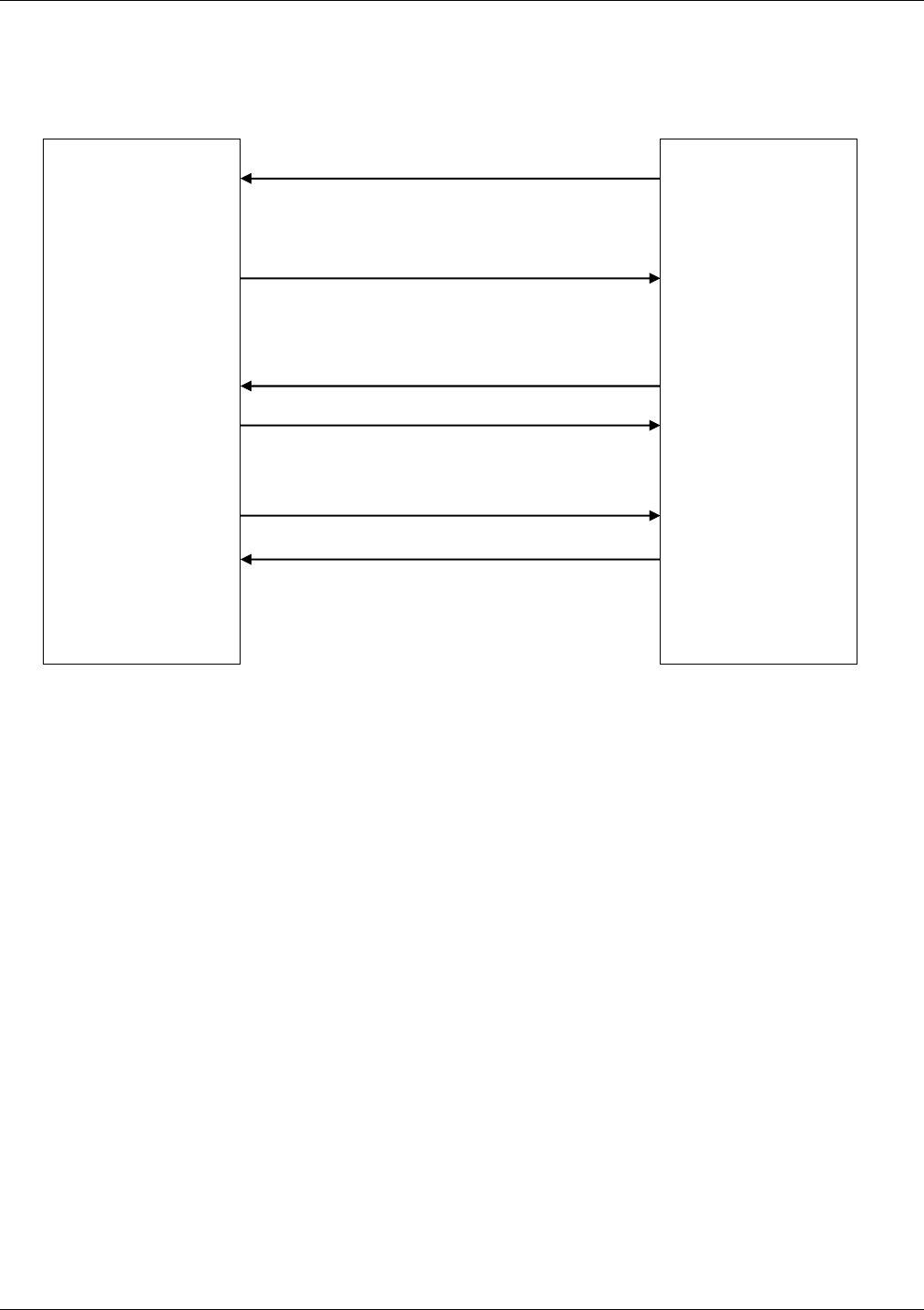
Chapter 16 – SIM ToolKit
Multi-Tech Systems, Inc. Wireless GSM/GPRS AT Commands - PN S000293E 114
Messages Exchanged During a SIM ToolKit Operation
The following scheme shows the SIM ToolKit commands and unsolicited results that are exchanged.
Step 1:
The customer application informs the modem which facilities are supported. This operation is performed with the +STSF
(SIM ToolKit Set Facilities) command, which also activates or deactivates the SIM ToolKit functionality.
Step 2:
An unsolicited result +STIN (SIM ToolKit indication) is sent by the product in order to indicate to the customer application
which command type the SIM Application ToolKit is running. The last SIM ToolKit indication can be requested by the
+STIN? command.
Step 3:
The customer application uses the +STGI (SIM ToolKit Get Information) command to get all the information about the SIM
ToolKit command, given by +STIN.
Step 4:
The customer application uses the +STGR (SIM ToolKit Give Response) to send its response (if any) to the SIM ToolKit
Application. The +STCR (SIM ToolKit Control response) indication is an unsolicited result sent by the SIM when Call
control functionality is activated and before the customer application has performed any outgoing call, SMS, SS, or USSD.
MULTI-TECH
Modem
Customer
Application
+STSF=X,XXXXXXXX
+STIN=X
+STGI=X
+STGI response
+STGR=X,XXXXXX
STEP 1: Configuration and Activation
STEP 2: SIM sends pro-active command
STEP 3: Customer application gets all the information.
STEP 4: User response is sent to the SIM.
+STCR:X

Chapter 16 – SIM ToolKit
Multi-Tech Systems, Inc. Wireless GSM/GPRS AT Commands - PN S000293E 115
SIM Toolkit Commands
SIM ToolKit Set Facilities +STSF
Description: This command allows SIM ToolKit facilities to be activated, deactivated or configured.
Values: <mode>
0 Deactivates the SIM ToolKit functionalities.
1 Activates the SIM ToolKit functionalities.
2 Configures the SIM ToolKit functionalities.
<Config>
(160060C01F – 5FFFFFFF7F) (hex format)
<Timeout>
1-255 Timeout for user responses (multiple of 10 seconds).
<Autoresponse>
0 Automatic response is not activated
1 Automatic response is activated
Notes about Autoresponse:
• The activation or deactivation of the SIM ToolKit functionalities requires the use of the +CFUN (Set phone
functionality) command to reset the product (this operation is not necessary if PIN is not entered yet).
• The <Config> parameter gives the coding of the TERMINAL PROFILE, precisely the list of SIM Application
ToolKit facilities that are supported by the customer application.
• The <Timeout> parameter (multiple of 10 seconds) sets the maximum time the user has for reacting (to select
an item, to input a text, etc).
• When the <Autoresponse> is activated, the +STIN indication for Play Tone (5), Refresh (7), Send SS (8), Send
SMS (9) or Send USSD (10) is automatically followed by the corresponding +STGI response.
Note about Bits:
Some bits are related to the product only and not to the customer application. The product automatically sets these bits
to either 0 or 1 whatever the user enters with the +STSF command. Those values are given in Appendix D.
Each facility is coded on 1 bit:
• bit = 1: facility is supported by the customer application.
• bit = 0: facility is not supported by the customer application.
Only the first five bytes of the TERMINAL PROFILE (Class 2) can be configured. The other are set to 0. (See structure
of TERMINAL PROFILE in APPENDIX E.)
Command syntax: +STSF=<mode>[,<config>][,<Timeout>][,<AutoResponse>]
Command Possible responses
AT+STSF=<Mode>[,<Config>]
[,<Timeout>][,<AutoResponse>]
OK
+CME ERROR: <err>
AT+STSF? +STSF: <Mode>,<Config>,<Timeout>,<Autoresponse>
AT+STSF=? +STSF: (0-2), (160060C01F - 5FFFFFFF7F),(1-255),(0-1)
OK

Chapter 16 – SIM ToolKit
Multi-Tech Systems, Inc. Wireless GSM/GPRS AT Commands - PN S000293E 116
SIM ToolKit Facilities Error Codes
+CME ERROR: 3 Operation not allowed. This error is returned when a wrong parameter is entered.
Example
AT+CMEE=1 Enable the reporting of mobile equipment errors
OK
AT+WIND=15 Set indications
OK
AT+CPAS Query ME Status
+CPAS: 0 ME is ready.
OK
AT+STSF=? Test command SIM ToolKit Set Facilities
+STSF: (0-2), (160060C01F – 5FFFFFFF7F),(1-255)
OK
AT+STSF?
+STSF: 0,”160060C000”,3 No activation of SIM ToolKit functionality
OK
AT+STSF=2,”5FFFFFFF7F” Set all SIM ToolKit facilities (class 3).
OK
AT+STSF=3 Syntax Error
+CME ERROR: 3
AT+STSF=1 Activation of SIM ToolKit functionality
OK
AT+CFUN=1 Reboot Software.
OK
AT+CPIN? Is the ME requiring a password?
+CPIN: SIM PIN Yes, SIM PIN required
AT+CPIN=0000
OK PIN OK
+WIND: 4 Init phase is complete
AT+STSF?
+STSF: 1,”5FFFFFFF7F”,3 SIM ToolKit functionality activated with all facilities
OK

Chapter 16 – SIM ToolKit
Multi-Tech Systems, Inc. Wireless GSM/GPRS AT Commands - PN S000293E 117
SIM ToolKit Indication +STIN
Unsolicited Result
In order to allow the customer application to identify the pro-active command sent via SIM ToolKit, a mechanism of
unsolicited SIM ToolKit indications (+STIN) is implemented.
Syntax: AT+STIN: <CmdType>
Option: <CmdType>
0 Indicates that a ‘Setup Menu’ pro-active command has been sent from the SIM.
1 Indicates that a ‘Display Text’ pro-active command has been sent from the SIM.
2 Indicates that a ‘Get Inkey’ pro-active command has been sent from the SIM.
3 Indicates that a ‘Get Input’ pro-active command has been sent from the SIM.
4 Indicates that a ‘Setup Call’ pro-active command has been sent from the SIM.
5 Indicates that a ‘Play Tone’ pro-active command has been sent from the SIM. (*)
6 Indicates that a ‘Sel Item’ pro-active command has been sent from the SIM.
7 Indicates that a ‘Refresh’ pro-active command has been sent from the SIM. (*)
8 Indicates that a ‘Send SS’ pro-active command has been sent from the SIM. (*)
9 Indicates that a ‘Send SMS’ pro-active command has been sent from the SIM. (*)
10 Indicates that a ‘Send USSD’ pro-active command has been sent from the SIM. (*)
11 Indicates that a ‘SETUP EVENT LIST’ pro-active command has been sent from the SIM.
98 Indicates the timeout when no response from user.
99 Indicates that a “End Session” has been sent from the SIM.
(*) if the automatic response parameter is activated, this indication is followed by the corresponding +STGI
response.
Last SIM ToolKit Indication
The last SIM ToolKit indication sent by the SIM can be requested by the AT+STIN? command. This command is only
usable between the sending of the STIN indication by the SIM (Step 2, Messages exchanged during a SIM ToolKit
operation) and the response of the user with the +STGI command (Step 3).
Command syntax: AT+STIN?
Command Possible responses
AT+STIN?
Note: Ask for the last SIM ToolKit indication sent by
the SIM
+STIN: 0
OK
Note: the last SIM ToolKit indication was a Setup Menu
AT+STGI=0 Note: Display the SIM ToolKit application menu
AT+STIN?
Note: Ask for the last SIM ToolKit indication sent by
the SIM
+CME ERROR: 4
Note: Operation not supported. The +STGI command has
been already used

Chapter 16 – SIM ToolKit
Multi-Tech Systems, Inc. Wireless GSM/GPRS AT Commands - PN S000293E 118
SIM ToolKit Get Information +STGI
Description: This command allows to get the information (text to display, menu information, priorities) of a pro-active
command sent from the SIM. The information is returned only after receiving a SIM ToolKit indication
(+STIN).)
Values: Values are listed after the Command Table
Command syntax: +STGI=<CmdType>
Command Possible responses
AT+STGI=<CmdType
>
See Table 1
+CME ERROR: <err>
AT+STGI=? +STGI: (0-11)
OK
Table of Command Types
Cmd
Type
Description Possible responses
0 Get information about Setup Menu
pro-active command.
+STGI: <Alpha Identifier menu>
+STGI: <Id1>,<NbItems>,<Alpha Id1 Label>,<Help Info>[,<NextActionId>]<CR><LF>
+STGI: <Id2>,<NbItems>,<Alpha Id2 Label>,<Help Info>[,<NextActionId>]<CR><LF>
[…]]
No action expected from SIM.
1 Get information about Display text pro-active
command.
+STGI: <Prior>,<Text>,<ClearMode>
No action expected from SIM.
2 Get information about Get Inkey pro-active
command.
+STGI: <Format>,<HelpInfo>[,<TextInfo>]
SIM expects key pressed (+STGR).
3 Get information about Get Input pro-active
command.
+STGI: <Format>,<EchoMode>,<SizeMin>,<SizeMax>,
<HelpInfo>[,<TextInfo>]
SIM expects key input (+STGR).
4 Get information about Setupt call pro-active
command.
+STGI: <Type>,<CalledNb>,<SubAddress>,<Class>
SIM expects user authorization (+STGR).
5 Get information about Play Tone pro-active
command.
+STGI: <ToneType>[,<TimeUnit>,<TimeInterval>,<TextInfo>]
No action.
6 Get information about Sel Item pro-active
command.
+STGI: <DefaultItem>, <Alpha Identifier menu><CR><LF>
+STGI: <Id1>,<NbItems>,<Alpha Id1 Label>,<Help Info>[,<NextActionId>]<CR><LF>
+STGI: <Id2>,<NbItems>,<Alpha Id2 Label>,<Help Info>[,<NextActionId>]<CR><LF>
[…]]
SIM expects an item choice (+STGR).
7 Get information about Refresh pro-active
command.
+STGI: <RefreshType>
No action (Refresh done automatically by product).
8 Get information about Send SS pro-active
command.
+STGI:<TextInfo>
No action (Send SS done automatically by product).
9 Get information about Send SMS pro-active
command.
+STGI: <TextInfo>
No action (Send SMS done automatically by product).
10 Get information about Send USSD pro-active
command.
+STGI: <TextInfo>
No action (Send USSD done automatically by product).
11 Get information about SETUP EVENT LIST
pro-active command.
+STGI: <Evt>
Values for the SIM ToolKit Get Information Command:
Values when CmdType=0 (Setup menu)
<Alpha Idenitifer menu> Alpha identifier of the main menu.
<Idx> (1-255) Menu item Identifier.
<NbItems> (1-255) Number of items in the main menu.
<Alpha Idx Label> Alpha identifier label of items in ASCII format.
<HelpInfo>
0 No help information available.
1 Help information available.
<NextActionId> Contains a pro-active command identifier.(see the table in APPENDIX F)
Compared to other commands the customer application can always get information about setup menu after having
received the +STIN:0 indication.

Chapter 16 – SIM ToolKit
Multi-Tech Systems, Inc. Wireless GSM/GPRS AT Commands - PN S000293E 119
Values when CmdType=1 (Display text)
<Prior>
0 Normal priority of display.
1 High priority of display.
<Text> Text to display in ASCII format.
<ClearMode>
0 Clear message after a delay (3 seconds)
1 Wait for user to clear message.
Values when CmdType=2 (Get Inkey)
<Format>
0 Digit (0-9, *, #,and +)
1 SMS alphabet default.
2 UCS2
<HelpInfo>
0 No help information available.
1 Help information available.
<TextInfo> Text information in ASCII format.
Values when CmdType=3 (Get Input)
<Format>
0 Digit (0-9, *, #,and +)
1 SMS alphabet default.
2 UCS2
3 Unpacked format.
4 Packed format.
<EchMode>
0 Echo off.
1 Echo on.
<SizeMin> (1-255) Minimum length of input.
<SizeMax> (1-255) Maximum length of input.
<HelpInfo>
0 No help information available.
1 Help information available.
<TextInfo> Text information in ASCII format.
Values when CmdType=4 (Setup Call)
<Type>
0 Set up call but only if not currently busy on another call.
1 Set up call, putting all other calls (if any) on hold.
2 Set up call, disconnecting all other calls (if any).
<CalledNb> Called party number in ASCII format.
<SubAdress> Called party sub-address in ASCII format.
<Class>
0 Voice call.
1 Data call.
2 Fax call
Values when CmdType=5 (Play tone)
<ToneType>
0 Tone Dial.
1 Tone Busy.
2 Tone Congestion.
3 Tone Radio ack
4 Tone Dropped.
5 Tone Error.
6 Tone Call waiting.
7 Tone Ringing.
8 Tone General beep.
9 Tone Positive beep.
10 Tone Negative beep.
<TimeUnit>
0 Time unit used is minutes.
1 Time unit used is seconds.
2 Time unit used is tenths of seconds.
<TimeInterval> (1-255) Time required expressed in units.
<TextInfo> Text information in ASCII format.

Chapter 16 – SIM ToolKit
Multi-Tech Systems, Inc. Wireless GSM/GPRS AT Commands - PN S000293E 120
Values when CmdType=6 (Sel Item)
<DefaultItem> (1-255) Default Item Identifier.
<Alpha Idenitifer menu> Alpha identifier of the main menu.
<Idx> (1-255) Identifier items.
<NbItems> (1-255) Number of items in the menu.
<Alpha Idx Label> Alpha identifier label of items in ASCII format.
<HelpInfo>
0 No help information available.
1 Help information available.
<NextActionId> Contains a pro-active command identifier. (see the table in APPENDIX F)
Values when CmdType=7 (Refresh)
<RefreshType>
0 SlM initialization and full file change notification.
1 File change notification.
2 SIM initialization and file change notification.
3 SIM initialization.
4 SIM reset.
Values when CmdType=8 (Send SS)
<TextInfo> Text information in ASCII format.
Values when CmdType=9 (Send SMS)
<TextInfo> Text information in ASCII format.
Values when CmdType=10 (Send USSD)
<TextInfo> Text information in ASCII format.
Values when CmdType=11 (Setup Event List)
<Evt>
1 Reporting asked for an ‘Idle Screen’ event.
2 Reporting asked for an ‘User Activity’ event.
3 Reporting asked for ‘Idle Screen’ and ‘User Activity’ events.
4 Cancellation of reporting event.
Rem: For the UCS2 format texts are displayed in Hexa Ascii format. Example: When the SIM sends a TextString
containing 0x00 0x41 the text displayed is “0041”.
Error Codes for the SIM ToolKit Get Information Command:
+ CME ERROR: 3 Operation not allowed. This error is returned when a wrong parameter is detected.
+CME ERROR: 4 Operation not supported. This error is returned when the user wants to get information about a
SIM ToolKit pro-active command (with SIM ToolKit functionality not activated.)
+CME ERROR: 518 SIM ToolKit indication not received. This error is returned when the SIM ToolKit indication
(+STIN) has not been received.
Example
Initially, all facilities are activated. The PIN is not required and SIM ToolKit functionality is activated.
AT+CMEE=1 Enable the reporting of mobile equipment errors
OK
AT+WIND=15 Set indications
OK
AT+STSF?
+STSF: 1,”5FFFFFFF7F”,3 SIM ToolKit functionality activated with all facilities.
OK
+STIN: 0 The main menu has been sent from the SIM.
AT+STIN?
+STIN: 0
OK
AT+STGI=0 Get information about the main menu
+STGI: ”SIM TOOLKIT MAIN MENU” Main menu contains 3 items.
+STGI: 1,3,”BANK”,0
+STGI: 2,3,”QUIZ”,0
+STGI: 3,3,”WEATHER”,0
OK
AT+STIN?
+CME ERROR: 4

Chapter 16 – SIM ToolKit
Multi-Tech Systems, Inc. Wireless GSM/GPRS AT Commands - PN S000293E 121
Unsolicited Result: SIM ToolKit Control Response
+STCR
Description: When the customer application makes an outgoing call or an outgoing SMS and if the call control facility
is activated, CALL CONTROL and SMS CONTROL responses can be identified. This is also applicable
to SS calls.)
Values: <Result>
0 Control response not allowed.
1 Control response with modification.
<Number> Called number, Service Center Address or SS String in ASCII format.
<MODestAddr> MO destination address in ASCII format.
<TextInfo> Text information in ASCII format.
Command Syntax: +STCR: <Result>[,<Number>,<MODestAddr>,<TextInfo>]
SIM ToolKit Give Response +STGR
Description: This command allows the application/user to select an item in the main menu, or to answer the following
proactive commands:)
• GET INKEY Key Pressed By The User.
• GET INPUT Message Entered By The User.
• SELECT ITEM Selected Item.
• SETUP CALL User Confirmation.
• DISPLAY TEXT User Confirmation To Clear The Message.
• SETUP EVENT LIST Reporting events.
It is also possible to terminate the current proactive command session by sending a Terminal Response
to the SIM, with the following parameters:
• BACKWARD MOVE Process a backward move
• BEYOND CAPABILITIES Command beyond ME capabilities
• UNABLE TO PROCESS ME is currently unable to process command
• NO RESPONSE No response from the user
• END SESSION User abort.
Command syntax: +STGR=<CmdType>[,<Result>,<Data>]
Command Possible responses
AT+STGR=<CmdType>[,<Result>,<Data>] OK
+CME ERROR: <err>
For GetInput with <Result>=1:
AT+STGR=3,1<CR>
<Data><Ctrl Z>
OK
+CME ERROR: <err>
For GetInkey with <Result>=1
AT+STGR=2,1,”<Data>”
OK
+CME ERROR: <err>
AT+STGR=? OK

Chapter 16 – SIM ToolKit
Multi-Tech Systems, Inc. Wireless GSM/GPRS AT Commands - PN S000293E 122
Values: <CmdType>
0 Item selection in the main menu.
1 User confirmation to clear a ‘Disp Text’.
2 Response for a ‘Get Inkey’.
3 Response for a ‘Get Input’.
4 Response for a ‘Setup call’.
6 Response for a ‘Sel Item’.
11 Reponse for a ‘Setup event list’.
95 Backward move
96 Command beyond ME capabilities
97 ME currently unable to process command
98 No response from the user.
99 User abort.
Values when CmdType=0 (Select an item from the main menu)
<Result>
1 Item selected by the user.
2 Help information required by user.
<Data> Contains the item identifier of the item selected by the user.
Values when CmdType=1 (Confirm the display text clearing)
No values.
Values when CmdType=2 (Get Inkey)
<Result>
0 Session ended by user.
1 Response given by the user.
2 Help information required by user.
<Data> Contains the key pressed by the user.
Values when CmdType=3 (Get Input)
<Result>
0 Session ended by user.
1 Response given by the user.
2 Help information required by user.
<Data> Contains the string of characters entered by the user.
Note: For Inputs in UCS2 format, the data are entered in ASCII format. Example: For
“8000410042FFFF” entered, the SIM receives 0x00 0x41 0x00 0x42 with UCS2 DCS. (See the
Appendix G about the different UCS2 syntaxes).
Values when CmdType=4 (Setup call)
<Result>
0 User refuses the call.
1 User accepts call.
Values when CmdType=6 (Select Item)
<Result>
0 Session terminated by the user
1 Item selected by the user
2 Help information required by the user
3 Return to the back item
<Data> Contains the item identifier selected by the user
Values when CmdType=11 (Setup Event List)
<Result>
1 Idle screen available.
2 User activity event.

Chapter 16 – SIM ToolKit
Multi-Tech Systems, Inc. Wireless GSM/GPRS AT Commands - PN S000293E 123
Sending a Terminal Response to the SIM:
Values when CmdType=95 (Backward Move)
Values when CmdType=96 (Command beyond ME capabilities)
Values when CmdType=97 (ME currently unable to process command)
Values when CmdType=98 (No response from the user)
Values when CmdType=99 (SIM ToolKit Session aborting by the user)
No values.
It is possible to send a Terminal Response after the +STIN indication (step 2, of Messages exchanged during a SIM
ToolKit operation), or after the +STGI command (step 3).
Note: For the SETUP MENU Proactive Command, it is only possible to send a Terminal Response after the +STIN:
0 indication, not after a +STGI=0 request. All of the Terminal Responses are not possible with all of the
Proactive Commands. Compatibility between available Terminal Responses and Proactive Commands is
given in Appendix D, Table 2. If a Terminal Response is attempted during a incompatible Proactive Command
session, a +CME ERROR: 3 will be returned.
Possible error codes
+ CME ERROR: 3 Operation not allowed. This error is returned when a wrong parameter is detected.
+CME ERROR: 4 Operation not supported. This error is returned when the user gives a response with
SIM ToolKit functionality not activated. Or if the SIM ToolKit indication (+STIN) has not
been received.
Example
Initially, all facilities are activated, the PIN is not required and the SIM ToolKit functionality is activated.
+STIN: 0 The main menu has been sent from the SIM.
AT+STGI=0 Get information about the main menu
+STGI: 1,3,”BANK”,0 The main menu contains 3 items.
+STGI: 2,3,”QUIZ”,0
+STGI: 3,3,”WEATHER”,0
OK
AT+STGR=0,1,1 The item 2 of the main menu has been selected.
OK
+STIN: 6 The Sel item menu has been sent from the SIM.
AT+STGI=6 Get information about the BANK menu
+STGI: 1,”BANK” The BANK menu contains two items.
+STGI: 1,2,”PERSONAL ACCOUNT ENQUIRY”,1
+STGI: 2,2,”NEWS”,0
OK
AT+STGR=6,1,1 Select Item 1.
OK
+STIN: 3 User request to enter Password sent.
AT+STGI=3 Get information about this request.
+STGI: 0,0,4,4,0,”Enter Account Password:’
OK
AT+STGR=3,1<CR> The user enters the Password.
>0000<Ctrl Z>
OK
+STIN:1 A text info has been sent from the SIM.
AT+STGI=1 Get information about this text.
+STGI: 0,”Password correct, please wait for response”,0
OK
+STIN: 9 SIM requests a bank account update from bank server via the network (SEND SMS)
AT+STGI=9 Get all information about the SEND SMS
+STGI: ”Send account balance of user, authorization ok”
OK
********* After a short period of time. ********
+STIN: 5 Transaction is complete: BEEP
+STGI=5 Get information about the Tone
+STGI: 9,1,1
+STIN: 1 Display text indication
AT+STGI=1
+STGI: 0,”Your account balance is 1000 $”,0
OK

Chapter 17 – GPRS Commands
Multi-Tech Systems, Inc. Wireless GSM/GPRS AT Commands - PN S000293E 124
Chapter 17 – GPRS commands
When using GSM-only software, GPRS commands are not available.
Define PDP Context +CGDCONT
Description: This command specifies PDP context parameter values for a PDP context identified by the local context
identification parameter, <cid>.
Four PDP contexts can be defined.
A special form of the set command, +CGDCONT= <cid> causes the values for context number <cid> to
become undefined.
The test command returns values supported as a compound value. If the modem supports several PDP
types, <PDP_type>, the parameter value ranges for each <PDP_type> are returned on a separate line.
The read command returns the current settings for each defined context.
The test command returns values supported as a compound value. If the modem supports several PDP
types, <PDP_type), the parameter value ranges for each <PDP_type> are returned on a separate line.
Values: <cid> (PDP Context Identifier) a numeric parameter (1-4) which specifies a particular PDP context
definition. The parameter is local to the DTE-modem interface and is used in other PDP
context-related commands.
<PDP_type> (Packet Data Protocol type) a string parameter which specifies the type of packet data
protocol
• IP Internet Protocol
• PPP Point to Point Protocol
<APN> (Access Point Name) a string parameter, which is a logical name that is used to select the
GGSN or the external packet data network. If the value is null or omitted, then the
subscription value will be requested.
<PDP_address> a string parameter that identifies the modem in the address space applicable to the
PDP. If the value is null or omitted, then a value may be provided by the DTE during the PDP
startup procedure or, failing that, a dynamic address will be requested. The read form of the
command will continue to return the null string even if an address has been allocated during
the PDP startup procedure. The allocated address may be read using the +CGPADDR
command.
<d_comp> a numeric parameter that controls PDP data compression
0 Off (default if value is omitted)
1 On
Other values are reserved.
<h_comp> a numeric parameter that controls PDP header compression
0 Off (default if value is omitted)
1 On
Other values are reserved.
Notes:
• At present only one data compression algorithm (V.42bis) is provided in SNDCP. If and
when other algorithms become available, a command will be provided to select one or more
of these.
• Four PDP contexts can be specified; however, only one can be activated at a time.

Chapter 17 – GPRS Commands
Multi-Tech Systems, Inc. Wireless GSM/GPRS AT Commands - PN S000293E 125
Command Syntax:
Command Possible responses
AT+CGDCONT=[<cid> [,<PDP_type>
[,<APN> [,<PDP_addr> [,<d_comp>
[,<h_comp>]]]]]]
OK
ERROR
AT+CGDCONT? +CGDCONT: <cid>, <PDP_type>, <APN>,<PDP_addr>, <data_comp>,
<head_comp>
[<CR><LF>+CGDCONT: <cid>, <PDP_type>, <APN>,<PDP_addr>,
<data_comp>, <head_comp>
[...]]
OK
AT+CGDCONT=? +CGDCONT: (range of supported <cid>s), <PDP_type>,,,(list of
supported <d_comp>s),
(list of supported <h_comp>s)
[<CR><LF>+CGDCONT: (range of supported <cid>s),
<PDP_type>,,,(list of supported <d_comp>s),(list of supported
<h_comp>s)
[...]]
OK
AT+CGDCONT: 1, “IP” “internet”;
AT+CGCONT=?
+CGCONT: (1-4), “IP”,,,(0-1,(0-1)
+CGCONT: (1-4), “PPP”,,,0,0,0
OK
AT+CGCONT? +CGCONT: 1, “IP”,”internet”,,0,0
+CGCONT: 2, “IP”,”abc.com”,,0,0
OK

Chapter 17 – GPRS Commands
Multi-Tech Systems, Inc. Wireless GSM/GPRS AT Commands - PN S000293E 126
Quality of Service Profile Requested +CGQREQ
Description: This command allows the DTE to specify a Quality of Service Profile that is used when the modem
sends an Activate PDP Context Request message to the network.
The set command specifies a profile for the context identified by the local context identification
parameter, <cid>. Since this is the same parameter that is used in the +CGDCONT command, the
+CGQREQ command is effectively an extension to the +CGDCONT command. The QoS profile
consists of a number of parameters, each of which may be set to a separate value.
A special form of the set command, +CGQREQ= <cid>, causes the requested profile for context
number <cid> to become undefined.
The read command returns the current settings for each defined context. The test command returns
values supported as a compound value. If the modem supports several PDP types, the parameter value
ranges for each PDP type are returned on a separate line.
Command Syntax:
Command Possible Response(s)
AT+CGQREQ=[<cid> [,<precedence > [,<delay>
[,<reliability.> [,<peak> [,<mean>]]]]]]
OK
ERROR
AT+CGQREQ? +CGQREQ: <cid>, <precedence >, <delay>, <reliability>,
<peak>, <mean>
[<CR><LF>+CGQREQ: <cid>, <precedence >, <delay>,
<reliability.>, <peak>, <mean>
[…]]
OK
AT+CGQREQ=? +CGQREQ: <PDP_type>, (list of supported <precedence>s),
(list of supported <delay>s), (list of supported <reliability>s) , (list
of supported <peak>s), (list of supported <mean>s)
[<CR><LF>+CGQREQ: <PDP_type>, (list of supported
<precedence>s), (list of supported <delay>s), (list of supported
<reliability>s) , (list of supported <peak>s), (list of supported
<mean>s)
[…]]
OK
AT +CGQREQ=1,1,4,5,2,14 OK
AT+CGQREQ=? +CGQREG: “IP”, (1-3), (1-4), (1-5), (1-9), (1-31)
+CGQREQ: “PPP”, (1-3), (1-4), (1-5), (1-9), (1-31)
OK
AT+CGQREQ? +CGQREQ: 1,1,4,5,2,14
OK
Summary List of Values:
<cid>: a numeric parameter that specifies a particular PDP context definition.
<precedence>: a numeric parameter that specifies the precedence class
<delay>: a numeric parameter that specifies the delay class
<reliability>: a numeric parameter that specifies the reliability class
<peak>: a numeric parameter that specifies the peak throughput class
<mean>: a numeric parameter that specifies the mean throughput class
Note: If a value is omitted for a particular class then the value is considered to be unspecified.
Details about Values:
<cid> Range 1- 3
<precedence>
0 Subscribed precedence - Subscribed by the Network by default if value is omitted
1 High priority - Service commitments shall be maintained ahead of precedence classes 2 and 3
2 Normal priority - Service commitments shall be maintained ahead of precedence class 3
3 Low priority - Service commitments shall be maintained after precedence classes 1 and 2
<delay>
0 Subscribed
1 Delay class 1
2 Delay class 2
3 Delay class 3
4 Delay class 4

Chapter 17 – GPRS Commands
Multi-Tech Systems, Inc. Wireless GSM/GPRS AT Commands - PN S000293E 127
Delay (maximum values)
SDU size: 128 bytes SDU size: 1024 bytes Delay Class
Mean Transfer Delay (sec) 95 percentile Delay (sec) Mean Transfer Delay (sec) 95 percentile Delay (sec)
Subscribed Subscribed by the Nwk / default if value is omitted
1. (Predictive) < 0.5 < 2 < 7
2. (Predictive) < 5 < 25 < 15 < 75
3. (Predictive) < 50 < 250 < 75 < 375
4. (Best Effort) Unspecified
<reliabiliy>
0 Subscribed
1 Up to 1 000 (8 kbit/s)
2 Up to 2 000 (16 kbit/s)
3 Up to 4 000 (32kbit/s)
4 Up to 8 000 (64 kbit/s)
5 Up to 16 000 (188 kbit/s)
6 Up to 32 000 (256 kbit/s)
7 Up to 64 000 (512 kbit/s)
8 Up to 128 000 (1 024 kbit/s)
9 Up to 256 000 (2 048 kbit/s)
Reliability
Class
GTP Mode LLC Frame Mode LLC Data
Protection
RLC Block
Mode
Traffic Type
0 Subscribed Subscribed by the Nwk / default if value is omitted
1 Acknowledged Acknowledged Protected Acknowledged Non real-time traffic, error-sensitive application
that cannot cope with data loss.
2 Unacknowledged Acknowledged Protected Acknowledged Non real-time traffic, error-sensitive application
that can cope with infrequent data loss.
3 Unacknowledged Unacknowledged Protected Acknowledged Non real-time traffic, error-sensitive application
that can cope with data loss, GMM/SM, & SMS.
4 Unacknowledged Unacknowledged Protected Unacknowledged Real-time traffic, error-sensitive application
that can cope with data loss.
5 Unacknowledged Unacknowledged Unprotected
U
nacknowledged Real-time traffic, error non-sensitive
application that can cope with data loss.
Note: For real-time traffic, the QoS profile also requires appropriate settings for delay and throughput.
<peak>
0 Subscribed
1 Up to 1 000 (8 kbit/s)
2 Up to 2 000 (16 kbit/s)
3 Up to 4 000 (32kbit/s)
4 Up to 8 000 (64 kbit/s)
5 Up to 16 000 (188 kbit/s)
6 Up to 32 000 (256 kbit/s)
7 Up to 64 000 (512 kbit/s)
8 Up to 128 000 (1 024 kbit/s)
9 Up to 256 000 (2 048 kbit/s)
<mean>
0 Subscribed by the Network by default if value is omitted
1 100 (~0.22 bit/s)
2 200 (~0.44 bit/s)
3 500 (~1.11 bit/s)
4 1 000 (~2.2 bit/s)
5 2 000 (~4.4 bit/s)
6 5 000 (~11.1 bit/s)
7 10 000 (~22 bit/s)
8 20 000 (~44 bit/s)
9 50 000 (~111 bit/s)
10 100 000 (~0.22 kbit/s)
11 200 000 (~0.44 kbit/s)
12 500 000 (~1.11 kbit/s)
13 1 000 000 (~2.2 kbit/s)
14 2 000 000 (~4.4 kbit/s)
15 5 000 000 (~11.1 kbit/s)
16 10 000 000 (~22 kbit/s)
17 20 000 000 (~44 kbit/s)
18 50 000 000 (~111 kbit/s)
31 Best effort

Chapter 17 – GPRS Commands
Multi-Tech Systems, Inc. Wireless GSM/GPRS AT Commands - PN S000293E 128
Quality of Service Profile Minimum Acceptable
+CGQMIN
Description: This command allows the DTE to specify a minimum acceptable profile which is checked by the modem
against the negotiated profile returned in the Activate PDP Context Accept message.
The set command specifies a profile for the context identified by the local context identification
parameter, <cid>. Since this is the same parameter that is used in the +CGDCONT command, the
+CGQMIN command is effectively an extension to the +CGDCONT command. The QoS profile consists
of a number of parameters, each of which may be set to a separate value.
A special form of the set command, +CGQMIN= <cid> causes the minimum acceptable profile for
context number <cid> to become undefined. In this case no check is made against the negotiated
profile.
The read command returns the current settings1 for each defined context. The test command returns
values supported as a compound value. If the modem supports several PDP types, the parameter value
ranges for each PDP type are returned on a separate line.
Values: <cid>: a numeric parameter which specifies a particular PDP context .
<precedence>: a numeric parameter which specifies the precedence class.
<delay>: a numeric parameter which specifies the delay class.
<reliability>: a numeric parameter which specifies the reliability class.
<peak>: a numeric parameter which specifies the peak throughput class.
<mean>: a numeric parameter which specifies the mean throughput class.
Note: If a value is omitted for a particular class then this class is not checked.
Command Syntax:
Command Possible Response(s)
AT+CGQMIN=[<cid> [,<precedence > [,<delay>
[,<reliability.> [,<peak> [,<mean>]]]]]]
OK
ERROR
AT+CGQMIN? +CGQMIN: <cid>, <precedence >, <delay>, <reliability>, <peak>,
<mean>
[<CR><LF>+CGQMIN: <cid>, <precedence >, <delay>,
<reliability.>, <peak>, <mean>
[…]]
OK
AT+CGQMIN=? +CGQMIN: <PDP_type>, (list of supported <precedence>s), (list of
supported <delay>s), (list of supported <reliability>s) , (list of
supported <peak>s), (list of supported <mean>s)
[<CR><LF>+CGQMIN: <PDP_type>, (list of supported
<precedence>s), (list of supported <delay>s), (list of supported
<reliability>s) , (list of supported <peak>s), (list of supported
<mean>s)
[…]]
OK
AT+CGQMIN = 1,1,4,5,2,31 OK
AT+CGQMIN=? +CGQMIN: “IP”,(1-3),(1-4),(1-5),(1-9),(1-31)
+CGQMIN: “PPP”,(1-3),(1-4),(1-5),(1-9),(1-31)
OK
AT+CGQMIN? +CGQMIN=? 1,1,4,5,2,14
OK

Chapter 17 – GPRS Commands
Multi-Tech Systems, Inc. Wireless GSM/GPRS AT Commands - PN S000293E 129
GPRS Attach or Detach +CGATT
Description: The execution command is used to attach the modem to, or detach the modem from, the GPRS service.
After the command has completed, the modem remains in V.25ter command state. If the modem is
already in the requested state, the command is ignored and the OK response is returned. If the
requested state cannot be achieved, an ERROR or +CME ERROR response is returned. Extended
error responses are enabled by the +CMEE command.
Any active PDP contexts will be automatically deactivated when the attachment state changes to
detached.
The read command returns the current GPRS service state. The test command is used for requesting
information on the supported GPRS service states.
Values: <state>: indicates the state of GPRS attachment
0 Detached
1 Attached
Other values are reserved and will result in an ERROR response to the execution command.
Command Syntax:
Command Possible Responses
AT+CGATT= [<state>] OK
ERROR
AT+CGATT? +CGATT: <state>
OK
AT+CGATT=? +CGATT: (list of supported <state>s)
OK
AT+CGATT=1 OK

Chapter 17 – GPRS Commands
Multi-Tech Systems, Inc. Wireless GSM/GPRS AT Commands - PN S000293E 130
PDP Context Activate or Deactivate +CGACT
Description: The execution command activates or deactivates the specified PDP context (s). After the command has
completed, the modem remains in V.25ter command state. If any PDP context is already in the
requested state, the state for that context remains unchanged.
If the requested state for any specified context cannot be achieved, an ERROR or +CME ERROR
response is returned. Extended error responses are enabled by the +CMEE command.
If the modem is not GPRS attached when the activation form of the command is executed, the modem
first performs a GPRS attach and them attempts to activate the specified contexts. If the attach fails
then the modem responds with ERROR or, if extended error responses are enabled, with the
appropriate failure-to-attach error message.
If no <cid>s are specified the activation form of the command activates the first activable defined
contexts. If no <cid>s are specified the deactivation form of the command deactivates all active
contexts.
One PDP context can be activated at the same time.
The read command returns the current activation states for all the defined PDP contexts.
The test command is used for requesting information on the supported PDP context activation states.
Values: <state>: indicates the state of PDP context activation
0 Deactivated
1 Activated
Other values are reserved and will result in an ERROR response to the execution command.
<cid>: a numeric parameter which specifies a particular PDP context.
Before a context can be activated, the modem must be attached to the GPRS network by
performing an automatic GPRS attach.
Command Syntax:
Command Possible Response(s)
AT+CGACT=[<state>
[,<cid>[,<cid>[,…]]]]
OK
ERROR
AT+CGACT? +CGACT: <cid>, <state>
[<CR><LF>+CGACT: <cid>, <state>
[...]]
OK
AT+CGACT=? +CGACT: (list of supported <state>s)
OK
AT+CGACT=1,1 OK
AT+CGACT? +CGACT: 1,1
OK
AT+CGACT=? +CGACT: (0-1)
OK

Chapter 17 – GPRS Commands
Multi-Tech Systems, Inc. Wireless GSM/GPRS AT Commands - PN S000293E 131
Enter Data State +CGDATA
Description: The command causes the modem to perform the necessary actions to set up communication between
the DTE and the network. This may include performing a GPRS attach and one PDP context
activations.
If the <cid> value is not defined to the modem, the modem will return an ERROR or +CME ERROR
response. Otherwise, the modem issues the intermediate result code CONNECT and enters V.25ter
online data state.
GPRS attachment and PDP context activation procedures may take place prior to or during the PDP
startup if they have not already been performed using the +CGATT and +CGACT commands.
If no <cid> is given, the modem attempts to activate the context with whatever information is available to
the modem. The other context parameters is set to their default values (No APN, default QOS
parameters, dynamic IP address requested).
If the activation is successful, data transfer may proceed.
After data transfer and layer 2 protocol termination procedure completion, the V.25ter command state is
re-entered and the modem returns the final result code OK.
In case of an abnormal termination or start up, the V.25ter command state is re-entered and the modem
returns the final result code NO CARRIER or, if enabled, +CME ERROR. Attach, activate and other
errors may be reported.
This command may be used in both normal and modem compatibility modes.
Note: The goal of this command is the same than ATD*99***.
Values:
<cid>: a numeric parameter which specifies a particular PDP context definition.
Command Syntax:
Command Possible Response(s)
AT+CGDATA=[<cid>] CONNECT
ERROR
AT+CGDATA=? +CGDATA:
OK
AT+CGDATA=? +CGDATA:
OK
AT+CGDATA=1 CONNECT

Chapter 17 – GPRS Commands
Multi-Tech Systems, Inc. Wireless GSM/GPRS AT Commands - PN S000293E 132
GPRS Mobile Station Class +CGCLASS
Description: The set command is used to set the modem to operate according to the specified GPRS mobile class. If
the requested class is not supported, an ERROR or +CME ERROR response is returned.
The read command returns the current GPRS mobile class.
The test command is used for requesting information on the supported GPRS mobile classes.
Defined Values:
<class>: a string parameter which indicates the GPRS mobile class (in descending order of
functionality)
A class A (highest)
B class B
CG class C in GPRS only mode
CC class C in circuit switched only mode (lowest)
Other values are reserved and will result in an ERROR response to the set command.
If the modem is GPRS attached when the set command is issued with a <class> = CC specified, a
GPRS detach request is sent to the network. If the modem is GSM attached when the set command is
issued with a <class> = CG specified, a GSM detach request is sent to the network.
Class A is not supported.
Note: During switch-On in CG class, the modem always performs an automatic GPRS attach (the
ATTACH-STATUS parameter of +WGPRS is ignored). But if the modem is not already GPRS-
attached when switching from B/CC class to CG class, then no automatic GPRS attach is
performed.
About the automatic attachment (see Note above):
AT+CGCLASS?
+CGCLASS: “B”
OK
AT+CGATT?
+CGATT: 0
OK
AT+CGCLASS=”CG”
OK
AT+CGATT?
+CGATT: 0
OK
AT+CGATT=1
OK
AT+CPOF
OK
AT+CFUN=1
OK
AT+CGCLASS?
+CGCLASS: “CG”
OK
AT+CGATT?
+CGATT: 1
OK
Command Syntax:
Command Possible Response(s)
AT+CGCLASS= [<class>] OK
ERROR
AT+CGCLASS? +CGCLASS: <class>
OK
AT+CGCLASS=? +CGCLASS: (list of supported <class>s)
OK
AT+CGCLASS=”CG”
Note: Enter GPRS Class C mode
OK
AT+CGCLASS=”CC”
Note: Enter GMS mode
OK
AT+CGCLASS=”A”
Note: Chosen class not supported
+CME ERROR: 150
AT+CGCLASS=? +CGCLASS: (“CG”,”CC”)
OK
AT+CGCLASS? +CGCLASS: (“CC”)
OK

Chapter 17 – GPRS Commands
Multi-Tech Systems, Inc. Wireless GSM/GPRS AT Commands - PN S000293E 133
Select Service for MO SMS Messages +CGSMS
Description: The set command specifies the service or service preference that the modem will use to send MO SMS
messages.
The read command returns the currently selected service or service preference.
The test command requests information on the currently available services and service preferences.
Values: <service>: a numeric parameter which indicates the service or service preference to be used
0 GPRS
1 Circuit switched
2 GPRS preferred (use circuit switched if GPRS is not available)
3 Circuit switched preferred (use GPRS if circuit switched not available)
Other values are reserved and will result in an ERROR response to the set command.
Command Syntax:
Command Possible Responses
AT+CGSMS= [<service>] OK
ERROR
At+CGSMS? +CGSMS: <service>
OK
AT+CGSMS=? +CGSMS: (list of currently available <service>s)
OK
AT +CGSMS=0 OK
AT+CGSMS=? +CGSMS=(0-3)
OK

Chapter 17 – GPRS Commands
Multi-Tech Systems, Inc. Wireless GSM/GPRS AT Commands - PN S000293E 134
GPRS Event Reporting +CGEREP
Description: Set command enables or disables sending of unsolicited result codes, +CGEV: XXX from modem to
DTE in the case of certain events occurring in the GPRS modem or the network.
<mode> controls the processing of unsolicited result codes specified within this command.
Read command returns the current mode and buffer settings.
Test command returns the modes and buffer settings supported by the modem as compound values.
Values: <mode>:
0 Buffer unsolicited result codes in the modem; if modem result code buffer is full, the oldest
ones can be discarded. No codes are forwarded to the DTE.
2 Buffer unsolicited result codes in the modem when modem-DTE link is reserved (e.g. in on-line
data mode) and flush them to the DTE when modem-DTE link becomes available; otherwise
forward them directly to the DTE.
<bfr>
0 Modem buffer of unsolicited result codes defined within this command is cleared when
<mode> 1 or 2 is entered. This is the only case supported.
1 Modem buffer of unsolicited result codes defined within this command is flushed to the DTE
when <mode> 2 is entered. This case is not supported.
The software provides a combination of all modes. When a serial link is available, indications are
forwarded directly to the DTE. If a serial link is reserved (e.g., in on-line data mode) or the modem
result code buffer is full, the oldest ones can be discarded.
Command Syntax:
Command Possible Responses
AT+CGEREP=[<mode>] OK
ERROR
AT+CGEREP? +CGEREP: <mode>,<bfr>
OK
AT+CGEREP=? +CGEREP: (list of supported <mode>s), (list of supported <bfr>s)
OK
Result Codes and Corresponding Events:
The following unsolicited result codes and the corresponding events are defined:
+CGEV: REJECT <PDP_type>, <PDP_addr>
A network request for PDP context activation occurred when the modem was unable to report it to the DTE with
a +CRING unsolicited result code and was automatically rejected.
+CGEV: NW REACT <PDP_type>, <PDP_addr>, [<cid>]
The network has requested a context reactivation. The <cid> that was used to reactivate the context is provided
if known to the modem.
+CGEV: NW DEACT <PDP_type>, <PDP_addr>, [<cid>]
The network has forced a context deactivation. The <cid> that was used to activate the context is provided if
known to the modem.
+CGEV: ME DEACT <PDP_type>, <PDP_addr>, [<cid>]
The mobile equipment has forced a context deactivation. The <cid> that was used to activate the context is
provided if known to the modem.
+CGEV: NW DETACH
The network has forced a GPRS detach. This implies that all active contexts have been deactivated. These are
not reported separately.
+CGEV: ME DETACH
The mobile equipment has forced a GPRS detach. This implies that all active contexts have been deactivated.
These are not reported separately.
+CGEV: NW CLASS <class>
The network has forced a change of MS class. The highest available class is reported.
+CGEV: ME CLASS <class>
The mobile equipment has forced a change of MS class. The highest available class is reported.

Chapter 17 – GPRS Commands
Multi-Tech Systems, Inc. Wireless GSM/GPRS AT Commands - PN S000293E 135
GPRS Network Registration Status +CGREG
Description: The set command controls the presentation of an unsolicited result code +CGREG: <stat> when <n>=1
and there is a change in the modem's GPRS network registration status, or code +CGREG:
<stat>[,<lac>,<ci>] when <n>=2 and there is a change of the network cell.
The read command returns the status of result code presentation and an integer <stat> which shows
whether the network has currently indicated the registration of the modem. Location information
elements <lac> and <ci> are returned only when <n>=2 and modem is registered in the network.
Values: <n>
0 Disable network registration unsolicited result code
1 Enable network registration unsolicited result code +CGREG: <stat>
2 Enable network registration and location information unsolicited result code +CGREG:
<stat>[,<lac>,<ci>]
<stat>
0 Not registered; the modem is not currently searching a new operator to which to register
1 Registered, home network
2 Not registered, but modem is currently searching a new operator to which to register
3 Registration denied
4 Unknown
5 Registered, roaming
<lac>
String type; two byte location area code in hexadecimal format
<ci>
String type; two byte cell ID in hexadecimal format
Command Syntax:
Command Possible response(s)
AT+CGREG=[<n>] +CGREG: stat>[,<lac>,<ci>]
OK
AT+CGREG? +CGREG: <n>,<stat>[,<lac>,<ci>]
OK
Note: +CME ERROR: <err>
AT+CGREG=? +CGREG: (list of supported <n>s)
OK
Request GPRS IP Service D
Description: This command causes the modem to perform whatever actions are necessary to establish
communication between the DTE and the external PDN.
The V.25ter 'D' (Dial) command causes the modem to enter the V.25ter online data state and, with the
DTE, to start the specified layer 2 protocol. The modem return CONNECT to confirm acceptance of the
command prior to entering the V.25ter online data state. No further commands may follow on the AT
command line.
The detailed behavior after the online data state has been entered is described briefly in clause 9, for
IP, of GSM 07.60. GPRS attachment and PDP context activation procedures may take place prior to or
during the PDP startup if they have not already been performed using the +CGATT and +CGACT
commands.
If <cid> is supported, its usage is the same as in the +CGDATA command. The +CGDCONT,
+CGQREQ, etc. commands may then be used in the modem initialization AT command string to set
values for for PDP type, APN, QoS etc…
If <cid> is not supported or is supported but omitted, the modem attempt to activate the context using
the 'Empty PDP type' (GSM 04.08). (No PDP address or APN is sent in this case and only one PDP
context subscription record is present in the HLR for this subscriber.)
Values: <GPRS_SC_IP>: (GPRS Service Code for IP) a digit string (value 99), which identifies a request to use
the GPRS with IP (PDP types IP and PPP)
<cid>: a digit string which specifies a particular PDP context definition.
Command Syntax:
Command Possible Responses
D*<GPRS_SC_IP>[***<cid>]# CONNECT
ERROR
Example: ATD*99***1#
CONNECT
ATD*99***2#
ERROR

Chapter 17 – GPRS Commands
Multi-Tech Systems, Inc. Wireless GSM/GPRS AT Commands - PN S000293E 136
Network Requested PDP Context Activation
In this mode of operation, the modem behaves like an answering modem and accepts the normal V.25ter commands
associated with answering a call. If GPRS-specific configuration commands are required, they may be sent to the modem
as part of the modem initialization commands. The +CGAUTO command is used to select modem compatibility mode.
Automatic response to a network request for PDP context activation S0
The V.25ter 'S0=n' (Automatic answer) command may be used to turn off (n=0) and on (n>0) the automatic response to a
network request for a PDP context activation.When the 'S0=n' (n>0) command is received, the modem attempt to perform
a GPRS attach if it is not already attached. Failure will result in ERROR being returned to the DTE. Subsequently, the
modem will announce a network request for PDP context activation by issuing the unsolicited result code RING to the
DTE, followed by the intermediate result code CONNECT. The modem then enters V.25ter online data state and follows
the same procedure as it would after having received a +CGANS=1 with no <L2P> or <cid> values specified.
Note: The 'S0=n' (n=0) command does not perform an automatic GPRS detach.
Manual acceptance of a network request for PDP context activation A
The V.25ter 'A' (Answer) command may be used to accept a network request for a PDP context activation announced by
the unsolicited result code RING. The modem responds with CONNECT, enters V.25ter online data state and follows the
same procedure as it would after having received a +CGANS=1 with no <cid> value specified. It is an error to issue the 'A'
command when there is no outstanding network request.
Manual rejection of a network request for PDP context activation H
The V.25ter 'H' or 'H0' (On-hook) command may be used to reject a network request for PDP context activation
announced by the unsolicited result code RING. The modem responds with OK. It is an error to issue the 'H' command
when there is no outstanding network request.
Note: This is an extension to the usage of the 'H' command that is described in ITU-T V.25ter.

Chapter 17 – GPRS Commands
Multi-Tech Systems, Inc. Wireless GSM/GPRS AT Commands - PN S000293E 137
Automatic Response to a Network Request for PDP
Context Activation +CGAUTO
Description: The set command disables or enables an automatic positive response (auto-answer) to the receipt of a
Request PDP Context Activation message from the network. It also provides control over the use of the
V.25ter basic commands 'S0', 'A and 'H' for handling network requests for PDP context activation. The
setting does not affect the issuing of the unsolicited result code RING or +CRING.
The test command returns values of <n> supported by the modem as a compound value.
When the +CGAUTO=0 command is received, the modem will not perform a GPRS detach if it is
attached. Subsequently, when the modem announces a network request for PDP context activation by
issuing the unsolicited result code RING or +CRING, the DTE may manually accept or reject the
request by issuing the +CGANS command or may simply ignore the network request.
When the +CGAUTO=1 command is received, the modem will attempt to perform a GPRS attach if it is
not already attached. Failure will result in ERROR or, if enabled, +CME ERROR being returned to the
DTE. Subsequently, when the modem announces a network request for PDP context activation by
issuing the unsolicited result code RING or +CRING to the DTE, this is followed by the intermediate
result code CONNECT. The modem then enters V.25ter online data state and follows the same
procedure as it would after having received a +CGANS=1 with <cid> values specified.
Values: <n>
0 Turn off automatic response for GPRS only
For <n> = 0 GPRS network requests are manually accepted or rejected by the +CGANS
command.
1 Turn on automatic response for GPRS only
For <n> = 1 GPRS network requests are automatically accepted according to the description
above.
2 Modem compatibility mode, GPRS only
For <n> = 2, automatic acceptance of GPRS network requests is controlled by the 'S0'
command. Manual control uses the 'A' and 'H' commands, respectively, to accept and reject
GPRS requests. (+CGANS may also be used.) Incoming circuit switched calls can be neither
manually nor automatically answered
3 Modem compatibility mode, GPRS and circuit switched calls (default)
For <n> = 3, automatic acceptance of both GPRS network requests and incoming circuit
switched calls is controlled by the 'S0' command. Manual control uses the 'A' and 'H'
commands, respectively, to accept and reject GPRS requests. (+CGANS may also be used.)
Circuit switched calls are handled as described elsewhere in this specification.
Note: In class C GPRS the modem can’t receive GPRS and GSM incoming calls simultaneously.
Command Syntax:
Command Possible response(s)
AT+CGAUTO=[<n>] OK
ERROR
AT+CGAUTO? +CGAUTO: <n>
OK
AT+CGAUTO=? +CGAUTO: (0-3)
OK
Example:
AT+CGAUTO=?
+CGAUTO: (0-2)
OK
AT+CGAUTO?
+CGAUTO: 2
OK
AT+CGAUTO=0
OK

Chapter 17 – GPRS Commands
Multi-Tech Systems, Inc. Wireless GSM/GPRS AT Commands - PN S000293E 138
Manual Response to a Network Request for PDP
Context Activation +CGANS
Description: The execution command requests the modem to respond to a network request for GPRS PDP context
activation which has been signalled to the DTE by the RING or +CRING: unsolicited result code. The
<response> parameter allows the DTE to accept or reject the request.
If <response> is 0, the request is rejected and the modem returns OK to the DTE.
If <response> is 1, the following procedure is followed by the modem.
PDP context activation procedures take place prior to or during the PDP startup.
One <cid> may be specified in order to provide the values needed for the context activation request.
During the PDP startup procedure the modem has the PDP type and the PDP address provided by the
network in the Request PDP Context Activation message.
If a <cid> is given his informations must matching with the PDP type and PDP address in the network
request as follows -
The PDP type must match exactly.
The PDP addresses are considered to match if they are identical or if the address in the context
definition is unspecified. If any of this information is in conflict, the command will fail.
The context is activated using the values for PDP type and PDP address provided by the network,
together with the other information found in the PDP context definition. An APN may or may not be
required, depending on the application. If no <cid> is given, the modem will attempt to activate the
context using the values for PDP type and PDP address provided by the network, together with any
other relevant information known to the modem. The other context parameters will be set to their default
values.
If the activation is successful, data transfer may proceed. After data transfer is complete, and the layer 2
protocol termination procedure has completed successfully, the V.25ter command state is re-entered
and the modem returns the final result code OK.
In the event of an erroneous termination or a failure to startup, the V.25ter command state is re-entered
and the modem returns the final result code NO CARRIER or, if enabled, +CME ERROR. Attach,
activate and other errors may be reported. It is also an error to issue the +CGANS command when
there is no outstanding network request.
This command may be used in both normal and modem compatibility modes.
Values: <response>: is a numeric parameter which specifies how the request should be responded to.
0 reject the request
1 accept and request that the PDP context be activated
If <response> is omitted it is assumed to be 0. Other values are reserved and will result in the
ERROR response.
<cid>: a numeric parameter which specifies a particular PDP context definition.
Command Syntax:
Command Possible response(s)
AT+CGANS=[<response>, [<cid>]] OK
ERROR
AT+CGANS=? +CGANS: (list of supported <response>s), (list of supported <L2P>s)
OK
Example:
+CRING: GPRS "IP", "122.41.74.238"
AT+CGANS=1
CONNECT
AT+CGANS=?
+CGANS= (0-1)
OK

Chapter 17 – GPRS Commands
Multi-Tech Systems, Inc. Wireless GSM/GPRS AT Commands - PN S000293E 139
Show PDP Address +CGPADDR
Description: The execution command returns a list of PDP addresses for the specified context identifiers.
The test command returns a list of defined <cid>s.
Values: <cid>: A numeric parameter which specifies a particular PDP context definition. If no <cid> is specified,
the addresses for all defined contexts are returned.
<PDP_address>: A string that identifies the modem in the address space applicable to the PDP. The
address may be static or dynamic. For a static address, it will be the one set by the +CGDCONT
command when the context was defined. For a dynamic address it will be the one assigned
during the last PDP context activation that used the context definition referred to by <cid>.
<PDP_address> is omitted if none is available.
Command Syntax:
Command Possible response(s)
AT+CGPADDR=[<cid> [,<cid> [,…]]] +CGPADDR: <cid>,<PDP_addr>
[<CR><LF>+CGPADDR: <cid>,<PDP_addr>
[...]]
OK
AT+CGPADDR=? +CGPADDR: (list of defined <cid>s)
OK
Example:
In this example, 3 <cid>s are defined:
AT+CGPADDR=1
+CGPADDR=1,"107.210.5.4"
OK
AT+CGPADDR=?
+CGAPDDR= (1-32)
OK
AT+CGPADDR
+CGPADDR: 1,
+CGPADDR: 2,"10.3.73.151"
+CGPADDR: 3,
+CGPADDR: 4,
Cellular Result Codes +CRC
Description: This command enables a more detailed ring indication, in case of incoming call (voice or data). Instead
of the string “RING”, an extended string is used to indicate which type of call is ringing (e.g. +CRING:
VOICE).
These extended indications are:
+CRING: ASYNC for asynchronous transparent
+CRING: REL ASYNC for asynchronous non-transparent
+CRING: VOICE for normal speech.
+CRING: FAX for fax calls
+CRING: GPRS GPRS network request for PDP context activation
If the modem is unable to announce to the DTE the network's request (for example it is in V.25ter online
data state) the modem reject the request. No corresponding unsolicited result code is issued when the
modem returns to a command state.
Values: No parameters
Command Syntax:
Command Possible responses
AT+CRC=0
Note: Extended reports disabled
OK
Note: Command valid
AT+CRC=1
Note: Extended reports enabled
OK
Note: Command valid
AT+CRC? +CRC: 1
OK
AT+CRC=? +CRC: (0,1)
OK

Chapter 17 – GPRS Commands
Multi-Tech Systems, Inc. Wireless GSM/GPRS AT Commands - PN S000293E 140
Service Reporting Control +CR
Description: This command enables a more detailed service reporting for incoming or outgoing calls. Before sending
the CONNECT response to the application, the GSM module will precisely define the type of data
connection being established.
These report types are:
+CR: ASYNC For asynchronous transparent
+CR: REL ASYNC For asynchronous non-transparent
+CR: GPRS For GPRS
Values: No parameters
Command syntax: AT+CR
Command Possible responses
AT+CR=0
Note: Extended reports disabled
OK
Note: Command valid
AT+CR=1
Note: Extended reports enabled
OK
Note: Command valid
Extended Error Report +CEER
Description: This command gives the reason of the call release when the last call setup (originating or answering)
failed. New indication for GPRS is the reason of the last unsuccessful PDP context activation and the
last GPRS detach or PDP context activation.
Values: No parameters
Command Syntax: AT+CEER
Command Possible Responses
ATD123456789 ;
Note: Outgoing voice call
NO CARRIER
Note: Call setup failure
AT+CEER
Note: Ask for reason of release
+CEER: Error <xxx>
OK
Note: <xxx>is the cause information element values form GSM
recommandation 04.08 or specific Call accepted
“NO CARRIER” indicates that the AT+CEER information is available for a failure diagnostic.
See Failure Cause from GSM 04.08 Recommendation in Appendix A.

Chapter 17 – GPRS Commands
Multi-Tech Systems, Inc. Wireless GSM/GPRS AT Commands - PN S000293E 141
GPRS Parameters Customization +WGPRS
Description: This command modifies some of the GPRS parameters, such as the ATTACH-STATUS (the modem
doesn’t automatically make a GPRS attachment after initialization), the PDP-INIT-STATUS (activate
automatically some defined PDP Contexts after initialization) and the use of NAT (IP address translation
on PPP). In addition, this command permits the automatic setting of some PDP contexts after
initialization.
Note: The modem must be rebooted to activate the new setup.
Values: <mode>: a numeric parameter which specifies a GPRS parameter:
0 ATTACH-STATUS (the modem doesn’t automatically make a GPRS attachment after init)
1 PDP-INIT-STATUS (automatically activate some define PDP Contexts after init)
2 Set ACTIVABLE automatically after init a define PDP context
3 NAT
<parameter>: a numeric parameter that control the <mode>
0 Off
1 On
<cid>: (PDP Context Identifier) a numeric parameter (1-32) which specifies a particular PDP context
definition. The parameter is local to the DTE-modem interface and is used in other PDP context-
related commands.
Note: When the module is set in “CG” class, the modem always automatically makes a GPRS
attachment after initialization, so AT+WGPRS? Always gives +WGPRS: 0,0 for the parameter 0.
Command Syntax: AT+WGPRS
AT+WGPRS=<mode>,<parameter>,[<cid>] OK
ERROR
AT+WGPRS=? +WGPRS: <mode>, <parameter1>,[<cid>]
[<CR><LF>+WGPRS: <mode>,
<parameter>,[<cid>]
[...]]
OK
AT+WGPRS? +WGPRS:<mode>(list of supported <parameter>),[(list of supported
<cid>)][<CR><LF>+WGPRS:<mode>(list of supported
<parameter>),[(list of supported <cid>)] [...]]
OK
Example:
AT+WGPRS=2,1,3 AT+WGPRS? +WGPRS: 2,0,3
OK +WGPRS: 0,0 +WGPRS: 2,0,4
AT+WGPRS=? +WGPRS: 1,0 +WGPRS: 3,1
+WGPRS: (0-3),(0-1),(0-4) +WGPRS: 2,1,1 OK
OK +WGPRS: 2,0,2 <CR><LF>

Chapter 17 – GPRS Commands
Multi-Tech Systems, Inc. Wireless GSM/GPRS AT Commands - PN S000293E 142
Full GPRS AT Command Examples
Activation of an IP PDP Context
Example 1
AT +CGDCONT=1, "IP", "internet"; +GCDCONT=2, "IP", "abc.com"
OK
ATD*99***1#
CONNECT
Example 2
AT +CGCLASS=”CG”
OK
+CGREG: 1
AT +CGDCONT=1, "IP", "internet"
OK
AT +CGQREQ=1,1,4,5,2,14
OK
AT +CGQMIN=1,1,4,5,2,14
OK
AT +CGATT=1
OK
AT +CGACT=1,1
OK
//Remark about +CGDATA: the goal of this command is the same as ATD*99***
AT +CGDATA=1
CONNECT
…….
Data transfer
…….
+CGEV: NW DETACH
Network Request
AT+CGAUTO=0
OK
+CRING: GPRS "IP", "211.45.89.152"
AT+CGANS=1
CONNECT
……. Data transfer

Chapter 17 – GPRS Commands
Multi-Tech Systems, Inc. Wireless GSM/GPRS AT Commands - PN S000293E 143
GPRS-Related Errors +CME ERROR
Errors related to a failure to perform an attach
Numeric Text
103 Illegal MS (#3)
106 Illegal ME (#6)
107 GPRS services not allowed (#7)
111 PLMN not allowed (#11)
112 Location area not allowed (#12)
113 Roaming not allowed in this location area (#13)
(Values in parentheses are GSM Technical Specification 04.08 cause codes.)
Errors related to a failure to Activate a Context
Numeric Text
132 service option not supported (#32)
133 requested service option not subscribed (#33)
134 service option temporarily out of order (#34)
149 PDP authentication failure
533 Missing or Unknown APN
(Values in parentheses are GSM Technical Specification 04.08 cause codes.)
Other GPRS errors
Numeric Text
150 invalid mobile class
148 unspecified GPRS error
Other values in the range 101 - 150 are reserved for use by GPRS
Also all other values below 256 are reserved
Specific GPRS Failure Cause for +CEER
Numeric Text
224 MS requested detach
225 NWK requested Detach
226 Unsuccessful attach cause NO SERVICE
227 Unsuccessful attach cause NO ACCESS
228 Unsuccessful attach cause GPRS SERVICE REFUSED
229 PDP deactivation requested by Nwk
230 PDP deactivation cause LLC link activation failed
231 PDP deactivation cause NWK reactivation with same TI
232 PDP deactivation cause GMM abort
233 PDP deactivation cause LLC or SNDCP failure
234 PDP unsuccessful activation cause GMM error
235 PDP unsuccessful activation cause NWK reject
236 PDP unsuccessful activation cause NO NSAPI available
237 PDP unsuccessful activation cause SM refuse
238 PDP unsuccessful activation cause MMI ignore

Chapter 18 – Other AT Commands
Multi-Tech Systems, Inc. Wireless GSM/GPRS AT Commands - PN S000293E 144
Chapter 18 – Other AT
Commands
V.25ter Recommendation
The commands not listed in this document are not supported. For these commands, the product will then answer with
"ERROR". All modulation control, error control and data compression commands are not recognized. An "ERROR" string
will be returned.
GSM 07.05 Recommendation
All the 07.05 commands not described in this manual are not implemented. The product will answer "ERROR" to these
commands.
GSM 07.07 Recommendation
All the 07.07 commands not described in this manual are not implemented. The product will answer "ERROR" to these
commands.

Appendix A – Result Codes, Failure Causes, Other Tables
Multi-Tech Systems, Inc. Wireless GSM/GPRS AT Commands - PN S000293E 145
Appendix A – Result Codes,
Failure Causes, Other Tables
Chapter Summary
The following tables are listed in Appendix A:
• ME error result code:+CME ERROR: <error>
• Message service failure result code: +CMS ERROR <er>
• Specific error results codes
• Failure Cause from GMS 05.08 recommendation (+CEER)
• Specific Failure Cause for +CEER
• GSM 04.11 Annex E-2: Mobile originating SM-transfer
• Unsolicited result codes
• Final result codes
• Intermediate result codes
• Parameter storage
• GMS sequences list
• Operator names
• Data Commands and Multiplexing
ME Error Result Code: +CME ERROR: <error>
<error> Meaning Resulting from the following commands
3 Operation not allowed All GSM 07.07 commands (+CME ERROR: 3)
4 Operation not supported All GSM 07.07 commands (+CME ERROR: 4)
5 PH-SIM PIN required (SIM lock) All GSM 07.07 commands (+CME ERROR: 5)
10 SIM not inserted All GSM 07.07 commands (+CME ERROR: 10)
11 SIM PIN required All GSM 07.07 commands (+CME ERROR: 11)
12 SIM PUK required All GSM 07.07 commands (+CME ERROR: 12)
13 SIM failure All GSM 07.07 commands (+CME ERROR: 13)
16 Incorrect password +CACM, +CAMM, +CPUC, +CLCK, +CPWD, +CPIN, +CPIN2 (+CME
ERROR: 16)
17 SIM PIN2 required +CPBW (FDN), +CLCK (FDN),
18 SIM PUK2 required +CACM, +CAMM, +CPUC, +CPBW (FDN), +CPIN, +CPIN2, +CLCK
(FDN), +CPWD
20 Memory full +CPBW
21 Invalid index +CPBR, +CPBW, ATD>[mem]index, +WMGO
22 Not found +CPBF, +CPBP, +CPBN, +CGSN, +WOPN, ATD>[mem]”name”
24 Text string too long +CPBW, +CPIN, +CPIN2, +CLCK, +CPWD
26 Dial string too long +CPBW, ATD, +CCFC
27 Invalid characters in dial string +CPBW
30 No network service +VTS, +COPS=?, +CLCK, +CCFC, +CCWA, +CUSD
32 Network not allowed – emergency calls only +COPS
40 Network personal PIN required (Network lock) All GSM 07.07 commands (+CME ERROR: 40)
103 Illegal MS (#3) +CGATT
106 Illegal ME (#6) +CGATT
107 GPRS services not allowed (#7) +CGATT
111 PLMN not allowed (#11) +CGATT
112 Location area not allowed (#12) +CGATT
113 Roaming not allowed in this area (#13) +CGATT
132 service option not supported (#32) +CGACT +CGDATA ATD*99
133 requested service option not subscribed (#33) +CGACT +CGDATA ATD*99
134 service option temporarily out of order (#34) +CGACT +CGDATA ATD*99
148 unspecified GPRS error All GPRS commands
149 PDP authentication failure +CGACT +CGDATA ATD*99
150 invalid mobile class +CGCLASS +CGATT

Appendix A – Result Codes, Failure Causes, Other Tables
Multi-Tech Systems, Inc. Wireless GSM/GPRS AT Commands - PN S000293E 146
Message Service Failure Result Code +CMS ERROR: <er>
<er> is defined as below:
<er> Meaning Resulting from the following commands
1 to 127 Error cause values from the GSM
recommendation 04.11 Annex E-2
+CMGS, +CMSS
301 SMS service of ME reserved +CSMS (with +CMS: ERROR 301)
302 Operation not allowed All SMS commands (+CMSS, +CMGL, +CPMS, +CSMP…
303 Operation not supported All SMS commands
304 Invalid PDU mode paramete
r
+CMGS, +CMGW
305 Invalid text mode paramete
r
+CMGS, +CMGW, +CMSS
310 SIM not inserted All SMS commands
311 SIM PIN required All SMS commands
312 PH-SIM PIN required All SMS commands
313 SIM failure All SMS commands
316 SIM PUK required All SMS commands
317 SIM PIN2 required All SMS commands
318 SIM PUK2 required All SMS commands
321 Invalid memory index +CMGR, +CMSS, +CMGD
322 SIM memory full +CMGW
330 SC address unknown +CSCA?, +CMSS, +CMGS
340 no +CNMA acknowledgement expected +CNMA
Specific Error Result Codes
<error> Meaning Resulting from the following commands
500 unknown error. All commands
512 MM establishment failure (for SMS). +CMGS, +CMSS (+CMS ERROR: 512)
513 Lower layer failure (for SMS) +CMGS, +CMSS (+CMS ERROR: 513)
514 CP error (for SMS). +CMGS, +CMSS (+CMS ERROR: 514)
515 Please wait, init or command processing in
progress.
All commands ( “+CME ERROR: 515” or “+CMS ERROR: 515”
)
517 SIM ToolKit facility not supported. +STGI
518 SIM ToolKit indication not received. +STGI
519 Reset the product to activate or change a
new echo cancellation algo.
+ECHO, +VIP
520 Automatic abort about get plmn list for an
incoming call.
+COPS=?
526 PIN deactivation forbidden with this SIM
card.
+CLCK
527 Please wait, RR or MM is busy. Retry your
selection later.
+COPS
528 Location update failure. Emergency calls
only.
+COPS
529 PLMN selection failure. Emergency calls
only.
+COPS
531 SMS not sent: the <da> is not in FDN
phonebook, and FDN lock is enabled. (for
SMS)
+CMGS, +CMSS (+CMS ERROR: 531)
532 the embedded application is activated so the
objects flash are not erased
+WOPEN
533 Missing or Unknown APN ATD*99 +GACT +CGDATA

Appendix A – Result Codes, Failure Causes, Other Tables
Multi-Tech Systems, Inc. Wireless GSM/GPRS AT Commands - PN S000293E 147
Failure Cause from GSM 04.08 Recommendation +CEER
Cause value Diagnostic
1 Unassigned (unallocated) number
3 No route to destination
6 Channel unacceptable
8 Operator determined barring
16 Normal call clearing
17 User busy
18 No user responding
19 User alerting, no answer
21 Call rejected
22 Number changed
26 Non selected user clearing
27 Destination out of order
28 Invalid number format (incomplete number)
29 Facility rejected
30 Response to STATUS ENQUIRY
31 Normal, unspecified
34 No circuit/channel available
38 Network out of order
41 Temporary failure
42 Switching equipment congestion
43 Access information discarded
44 Requested circuit/channel not available
47 Resources unavailable, unspecified
49 Quality of service unavailable
50 Requested facility not subscribed
55 Incoming calls barred with in the CUG
57 Bearer capability not authorized
58 Bearer capability not presently available
63 Service or option not available, unspecified
65 Bearer service not implemented
68 ACM equal to or greater than ACMmax
69 Requested facility not implemented
70 Only restricted digital information bearer capability is available
79 Service or option not implemented, unspecified
81 Invalid transaction identifier value
87 User not member of CUG
88 Incompatible destination
91 Invalid transit network selection
95 Semantically incorrect message
96 Invalid mandatory information
97 Message type non-existent or not implemented
98 Message type not compatible with protocol state
99 Information element non-existent or not implemented
100 Conditional IE error
101 Message not compatible with protocol state
102 Recovery on timer expiry
111 Protocol error, unspecified
127 Interworking, unspecified
224 MS requested detach
225 PDP unsuccessful activation cause MMI ignore
226 NWK requested Detach
227 Unsuccessful attach cause NO SERVICE
228 Unsuccessful attach cause NO ACCESS
229 Unsuccessful attach cause GPRS SERVICE REFUSED
230 PDP deactivation requested by Nwk
231 PDP deactivation cause LLC link activation failed
232 PDP deactivation cause NWK reactivation with same TI
233 PDP deactivation cause GMM abort
234 PDP deactivation cause LLC or SNDCP failure
235 PDP unsuccessful activation cause GMM error
236 PDP unsuccessful activation cause NWK reject
237 PDP unsuccessful activation cause NO NSAPI available
238 PDP unsuccessful activation cause SM refuse
All other values in the range 0 to 31 shall be treated as cause 3. All other values in the range 32 to 47 shall be treated as cause 47.
All other values in the range 48 to 63 shall be treated as cause 63. All other values in the range 64 to 79 shall be treated as cause 79.
All other values in the range 80 to 95 shall be treated as cause 95. All other values in the range 96 to 111 shall be treated as cause 111.
All other values in the range 112 to 127 shall be treated as cause 127.

Appendix A – Result Codes, Failure Causes, Other Tables
Multi-Tech Systems, Inc. Wireless GSM/GPRS AT Commands - PN S000293E 148
Specific Failure Cause for +CEER
Cause value Diagnostic
240 FDN is active and number is not in FDN
241 Call operation not allowed
252 Call barring on outgoing calls
253 Call barring on incoming calls
254 Call impossible
255 Lower layer failure
GSM 04.11 Annex E-2: Mobile Originating SM-Transfer
These error causes could appear for SMS commands (+CMGS, +CMSS, +CMGD…)
Cause No. 1: "Unassigned (unallocated) number"
This cause indicates that the destination requested by the Mobile Station cannot be reached because, although the number is in a
valid format, it is not currently assigned (allocated).
Cause No. 8: "Operator determined barring"
This cause indicates that the MS has tried to send a mobile originating short message when the MS's network operator or service
provider has forbidden such transactions.
Cause No. 10: "Call barred"
This cause indicates that the outgoing call barred service applies to the short message service for the called destination.
Cause No. 21: "Short message transfer rejected"
This cause indicates that the equipment sending this cause does not wish to accept this short message, although it could have
accepted the short message since the equipment sending this cause is neither busy nor incompatible.
Cause No. 27: "Destination out of service"
This cause indicates that the destination indicated by the Mobile Station cannot be reached because the interface to the destination
is not functioning correctly. The term "not functioning correctly" indicates that a signaling message was unable to be delivered to the
remote user; e.g., a physical layer or data link layer failure at the remote user, user equipment off-line, etc.
Cause No. 28: "Unidentified subscriber"
This cause indicates that the subscriber is not registered in the PLMN (e.g.. IMSI not known)
Cause No. 29: "Facility rejected"
This cause indicates that the facility requested by the Mobile Station is not supported by the PLMN.
Cause No. 30: "Unknown subscriber"
This cause indicates that the subscriber is not registered in the HLR (e.g.. IMSI or directory number is not allocated to a subscriber).
Cause No. 38: "Network out of order"
This cause indicates that the network is not functioning correctly and that the condition is likely to last a relatively long period of time;
e.g., immediately reattempting the short message transfer is not likely to be successful.
Cause No. 41: "Temporary failure"
This cause indicates that the network is not functioning correctly and that the condition is not likely to last a long period of time; e.g.,
the Mobile Station may wish to try another short message transfer attempt almost immediately.
Cause No. 42: "Congestion"
This cause indicates that the short message service cannot be serviced because of high traffic.
Cause No. 47: "Resources unavailable, unspecified"
This cause is used to report a resource unavailable event only when no other cause applies.
Cause No. 69: "Requested facility not implemented"
This cause indicates that the network is unable to provide the requested short message service.
Cause No. 81: "Invalid short message transfer reference value"
This cause indicates that the equipment sending this cause has received a message with a short message reference which is not
currently in use on the MS-network interface.
Cause No. 95: "Invalid message, unspecified"
This cause is used to report an invalid message event only when no other cause in the invalid message class applies.
Cause No. 96: "Invalid mandatory information"
This cause indicates that the equipment sending this cause has received a message where a mandatory information element is
missing and/or has a content error (the two cases are undistinguishable).
Cause No. 97: "Message type non-existent or not implemented"
This cause indicates that the equipment sending this cause has received a message with a message type it does not recognize
either because this is a message not defined or defined but not implemented by the equipment sending this cause.
Cause No. 98: "Message not compatible with short message protocol state"
This cause indicates that the equipment sending this cause has received a message such that the procedures do not indicate that
this is a permissible message to receive while in the short message transfer state.
Cause No. 99: "Information element non-existent or not implemented"
This cause indicates that the equipment sending this cause has received a message which includes unrecognized information
elements because the information element identifier is not defined or it is defined but not implemented by the equipment sending the
cause. However, the information element is not required to be present in the message so that the equipment sends the cause to
process the message.
Cause No. 111: "Protocol error, unspecified"
This cause is used to report a protocol error event only when no other cause applies.
Cause No. 127: "Interworking, unspecified"
This cause indicates that there has been interworking with a network which does not provide causes for actions it takes; thus, the
precise cause for a message which is being sent cannot be determineed. All values other than specified should be treated as error
Cause No 41.

Appendix A – Result Codes, Failure Causes, Other Tables
Multi-Tech Systems, Inc. Wireless GSM/GPRS AT Commands - PN S000293E 149
Unsolicited Result Codes
Verbose Result Code Numeric (V0 set) Description
+CALA: < time string>,<index> As verbose Alarm notification
+CBM: <length><pdu> (PDU)
or
+CBM:<sn>,<mid>,<dcs>,<page>,<pages>…
(Text mode)
As verbose Cell Broadcast Message directly displayed
+CBMI: “BM”,<index> As verbose Cell Broadcast Message stored in mem at location <index>
+CCCM: <ccm> As verbose Current Call Meter value
+CCED: <values> As verbose (specific) Cell Environment Description indication
+CCWA:<number>,<type>, <class> [,<alpha>] As verbose Call Waiting number
+CDS: <fo>, <mr>… (text mode)
or +CDS: <length>,… (PDU)
As verbose SMS status report after sending a SMS
+CDSI: <mem>,<index> As verbose Incoming SMS Status Report after sending a SMS, stored in
<mem> (“SR”) at location <index>
+CKEV: <keynb> As verbose Key press or release
+CLIP: <number>, <type> [,,,<alpha>] As verbose Incoming Call Presentation
+CMT: <oa>… (text mode)
or +CMT: [<alpha>,]… (PDU)
As verbose Incoming message directly displayed
+CMTI: <mem>,<index> As verbose Incoming message stored in <mem> (“SM”) at location <index>
+CREG: <stat> [,<lac>,<ci>] As verbose Network registration indication
+CRING: <type> As verbose Incoming call type (VOICE, FAX ...)
+CSQ: <RxLev>,99 As verbose Automatic RxLev indication with AT+CCED=1,8 command
+CSSU: <code2>[<number>,<type>] As verbose Supplementary service notification during a call
+STIN: <ind> As verbose (specific) SIM ToolKit Indication
+WIND: <IndicationNb> [,<CallId>] As verbose (specific) Specific unsolicited indication (SIM Insert/Remove, End of init,
Reset, Alerting, Call creation/release)
+WVMI: <LineId>,<Status> As verbose (specific) Voice Mail Indicator notification (cf. +CPHS command)
+WDCI: <LineId>,<Status> As Verbose (specific) Diverted call indicator
RING 2 Incoming call signal from network
+CIEV As Verbose (specific) Indicator event reporting
Final Result Codes
Verbose Result Code Numeric (V0 set) Description
+CME ERROR: <err> As verbose Error from GSM 07.05 commands
+CMS ERROR: <err> As verbose Error from SMS commands (07.07)
BUSY 7 Busy signal detected
ERROR 4 Command not accepted
NO ANSWER 8 Connection completion timeout
NO CARRIER 3 Connection terminated
OK 0 Acknowledges correct execution of a command line
RING 2 Incoming call signal from network
Intermediate Result Codes
Verbose Result Code Numeric (V0 set) Description
+COLP:<number>,<type> as verbose Outgoing Call Presentation
+CR: <type> as verbose Outgoing Call report control
+ILRR: <rate> as verbose Local TA-TE data rate
CONNECT 300 10 Data connection at 300 bauds
CONNECT 1200 11 Data connection at 1200 bauds
CONNECT 1200/75 12 Data connection at 1200/75 bauds
CONNECT 2400 13 Data connection at 2400 bauds
CONNECT 4800 14 Data connection at 4800 bauds
CONNECT 9600 15 Data connection at 9600 bauds
CONNECT 14400 16 Data connection at 14400 bauds
+CSSI: <code1>[,<index>] As verbose Supplementary service notification during a call setup

Appendix A – Result Codes, Failure Causes, Other Tables
Multi-Tech Systems, Inc. Wireless GSM/GPRS AT Commands - PN S000293E 150
Parameter Storage Mode
Parameter Storage Mode
Command AT&W
(
E2P
)
Command
(
E2P
)
AT+CSAS
(
SIM
,
E2P
)
A
T&F (SIM,
E2P
)
Default values
General commands
+CMEE X X 0
+CSCS X X “PCCP437”
+WPCS X X “TRANSPARENT”
Call Control commands
%D X X 0
ATS0 X X 0 (no auto-answer)
+CICB X X 2 (speech)
+CSNS X X 0 (voice)
+ECHO X X ,1,0,3,10,7 (Algo ID 1)
,3,30,8000,256 (Algo ID 3)
+SIDET X X 1,1
+SPEAKER X X 0 (Spk 1 & Mic 1)
+VGR X X 64 (speaker 1)
32 (speaker 2)
+VGT X X 64 (mic 1 & ctrl 1)
0 (others)
Network Service commands
+COPS X X X 0,2
+CREG X X 0
Phonebook commands
+WAIP X X 0
+CSVM X X 0
SMS commands
+CMGF X X 1 (text)
+CNMI X X 0,1,0,0,0
+CSCA X
SIM dependant (phase 2)
+CSDH X X 0
+CSMP
X X 1,167,0,0
+CSMS X 0
+WUSS X X 0
Supplementary Services commands
+CCUG X 0,0,0
+CCWA X X 0
+CLIP X X 0
+COLP X X 0
+CSSN X X 0,0
+CUSD X X 0
Data commands
%C X X 0
\N X X 0
+CBST X X 0,0,1
+CR X X 0
+CRC X X 0
+CRLP X X 61,61,48,6,1
+DOPT X X 1,1
+DS X X 3,0,4096,20
+DR X X 0
+ILRR X X 0
Fax Class 2 commands
+FBOR X X 0
+FCQ X X 0
+FCR X X 1
+FDCC,+FDIS X X 0,5,0,0,2,0,0,0,0
+FPHCTO X X 30
V24 – V25 commands
&C X 1
&D X 1
&S X 1
E X 1
Q X X 0
V X X 1
+ICF X 3,4
+IFC X 2,2
+IPR X 9600

Appendix A – Result Codes, Failure Causes, Other Tables
Multi-Tech Systems, Inc. Wireless GSM/GPRS AT Commands - PN S000293E 151
Parameter Storage Mode
Command AT&W
(
E2P
)
Command
(
E2P
)
AT+CSAS
(
SIM
,
E2P
)
A
T&F (SIM,
E2P
)
Default values
+WMUX X X 0
Specific commands
+ADC X X 0
+CMER X X 0
+CPHS X X ,0
+WCDM X X 0,0
+WDR X 2
+WIND X X 0
+WIOM X 255,0
+WRIM X X 0
+WSVG X X 0
+WVR X 5
SIM ToolKit commands
+STSF X 0,”160060C01F”,3,0
GPRS commands
+GCAUTO X X 3
+GCCLASS X “B”
+GCDCONT X
+GCEREP X X 0
+GCREG X X 0
+GCSMS X 1
+WGPRS X 0,1
1,0
3,0

Appendix A – Result Codes, Failure Causes, Other Tables
Multi-Tech Systems, Inc. Wireless GSM/GPRS AT Commands - PN S000293E 152
GSM Sequences List
In accordance with GSM Technical Specification 02.30, the product supports the following GSM sequences, which can be used
through the ATD and the +CKPD commands.
Security
**04*OLDPIN*NEWPIN*NEWPIN# Change PIN code
**042*OLDPIN2*NEWPIN2*NEWPIN2# Change PIN2 code
**05*PUK*NEWPIN*NEWPIN# Unlock PIN code
**052*PUK2*NEWPIN2*NEWPIN2# Unlock PIN2 code
*#06# Show the IMEI number
Call Forwarding
*SC# or
*SC**bs#
Activate
**SC*PhoneNumber# or Register and activate
**SC*PhoneNumber*BS# or
**SC*PhoneNumber*[BS]*T# or
*SC*PhoneNumber# or
*SC*PhoneNumber*BS# or
*SC*PhoneNumber*[BS]*T#
*#SC# or *#SC**BS# Check status
#SC# or
#SC**BS#
Deactivate
##SC# or ##SC**BS# Unregistered and deactivate
The Service codes (SC) are:
002 all call forwarding
004 all conditional call forwarding
21 call forwarding unconditional
61 call forwarding on no answer
62 call forwarding on not reachable
67 call busy
The Network service codes (BS) are:
No code All tele and bearer services
10 All teleservices
11 Telephony
12 All data teleservices
13 Fax services
16 Short Message Services
17 Voice Group Call Service
18 Voice Broadcast Service
19 All teleservices except SMS
20 All bearer services
21 All asynchronous services
22 All synchronous services
24 All data circuit synchronous
25 All data circuit asynchronous
26 All dedicated packet access
27 All dedicated PAD access
The no reply condition timer (T) is only used for SC = 002, 004 or 61.

Appendix A – Result Codes, Failure Causes, Other Tables
Multi-Tech Systems, Inc. Wireless GSM/GPRS AT Commands - PN S000293E 153
Call Barring
*SC*Password# or *SC*Password*BS# Activate
*#SC# or *#SC**BS# Check status
#SC*Password# or #SC*Password*BS# Deactivate
**03*330*OLDPWD*NEWPWD*NEWPWD# Change password for call barring
**03**OLDPWD*NEWPWD*NEWPWD#
*03*330*OLDPWD*NEWPWD*NEWPWD#
*03**OLDPWD*NEWPWD*NEWPWD#
The Service codes (SC) are:
33 call barring of outgoing call
330 all barring service (only for deactivation)
331 call barring of outgoing international call
332 call barring of outgoing international calls except to HPLMN
333 all outgoing barring service (only for deactivation)
35 call barring of incoming calls
351 call barring of incoming calls if roaming
353 all incoming barring service (only for deactivation)
Note: Network service codes (BS) are the same the call forwarding sequences.
Call Waiting
*43# Activate
*#43# Check status
#43# Deactivate
Number Presentation
*#30# CLIP check status
*#31# CLIR check status
*31#PhoneNumber Invoke CLIR for a voice call
#31#PhoneNumber Suppress CLIR for a voice call
*#76# COLP check status

Appendix A – Result Codes, Failure Causes, Other Tables
Multi-Tech Systems, Inc. Wireless GSM/GPRS AT Commands - PN S000293E 154
Operator Names
Country
Initials
MCC MNC Preferred Presentation of Country
Initials and Mobile Network Name
Abbreviated Mobile
Network Name
A 311 140 Sprocket Sprocket
A 332 011 Blue Sky Blue Sky
A 232 01 A1 A1
A 232 003 T-Mobile A TMO A
A 232 005 A One one
A 232 007 A tele.ring telering
A 232 010 3 AT 3 AT
ABW 363 001 SETAR GSM SETARGSM
AF 412 001 AF AWCC AWCC
AGO 631 002 UNITEL UNITEL
AL 276 001 AMC-AL A M C
AL 276 002 vodafone AL voda AL
ALG 603 001 ALGERIAN MOBILE NETWORK AMN
ALG 603 002 Djezzy Djezzy
AN 344 030 APUA PCS ANTIGUA APUA-PCS
AND 213 003 STA-MOBILAND M-AND
ANT 362 051 Telcell GSM Telcell
ANT 362 069 ANT CURACAO TELECOM CT GSM
ANT 362 091 UTS Wireless Curacao N.V. UTS
AR 722 034 PERSONAL AR TP
ARG 722 007 UNIFON UNIFON
ARG 722 035 PORT-HABLE P-HABLE
AS 544 011 Blue Sky Blue Sky
AUS 505 001 Telstra Mobile Telstra
AUS 505 002 YES OPTUS AUS Optus
AUS 505 003 VODAFONE AUS VFONE
AUS 505 006 H3GA H3GA
AZE 400 001 AZE-AZERCELL GSM ACELL
AZE 400 002 BAKCELL GSM 2000 BKCELL
B 206 010 B mobistar mobi*
BA 218 003 BA-ERONET ERONET
BA 218 005 MOBI’S MOBI’S
BA 218 090 BIH GSMBIH GSMBIH
BD 470 003 DB SHEBAWORLD SHEBA
BDA 350 001 TELECOM BDA TELE BDA
BE 206 020 BASE BASE
BEL 206 001 BEL PROXIMUS PROXI
BEN 616 002 TELECEL BENIN TLCL-BEN
BEN 616 003 BJ BENINCELL BENCELL
BEN 616 004 BELL BENIN COMMUNICATION BB COM
BF 002 002 BF CELTEL CELTEL
BG 284 001 M-TEL GSM BG M-TEL
BG 284 005 BG GLOBUL GLOBUL
BGD 470 001 BGD-GP GP
BGD 470 002 BGD AKTEL AKTEL
BHR 426 001 BATELCO BATELCO
BI 642 001 Spacetel BI SPACETEL
BL 702 067 BTL BTL
BMU 350 002 BTC MOBILITY LTD. MOBILITY
BO 736 002 MOVIL-E BOMOV
BOL 736 001 NUEVATEL VIVA
BRA 724 001 TIM BRASIL TIM
BRA 724 002 TIM BRASIL TIM
BRA 724 003 TIM BRASIL TIM
BRA 724 004 TIM BRASIL TIM
BRA 724 031 Oi Oi
BRU 528 11 BRU-DSTCom DSTCom
BTN 402 017 BT B-MOBILE B-MOBILE
BUR 642 002 BUSAFA SAFARIS
BW 652 001 BW MASCOM MASCOM
BW 652 002 BW VISTA VISTA
BY 257 001 BY VELCOM VELCOM
CAM 624 002 Orange CAM Orange
CAN 302 370 Microtell MCELL

Appendix A – Result Codes, Failure Causes, Other Tables
Multi-Tech Systems, Inc. Wireless GSM/GPRS AT Commands - PN S000293E 155
Country
Initials
MCC MNC Preferred Presentation of Country
Initials and Mobile Network Name
Abbreviated Mobile
Network Name
CAN 302 720 Rogers AT&T Wireless ROGERS
CD 629 001 CELTEL CD CDLTEL
CD 630 089 CD OASIS OASIS
CH 228 001 SWISS GSM SWISS
CH 228 002 Sunrise Sunrise
CH 228 003 Orange CH Orange
CHN 460 000 CHINA MOBILE CMCC
CHN 460 001 CHN-CUGSM CU-GSM
CI 612 001 CI CORA CORA
CI 612 003 Orange CI Orange
CI 612 005 TELECEL-Cl TELCEL
CL 730 001 ENTEL PCS ENTEL PCS
CL 730 010 ENTEL PCS ENTEL PCS
CMR 624 001 MTN CAM 62401
COG 629 010 COG LIBERTIS LIBERTIS
CPV 625 001 CPV MOVEL CMOVEL
CRI 712 001 I.C.E. I.C.E.
CU 368 001 CU/C_COM C_COM
CY 280 001 CY CYTAGSM CY-GSM
CZ 230 001 T-Mobile CZ TMO CZ
CZ 230 002 EUROTEL – CZ ET - CZ
CZ 230 003 OSKAR OSKAR
D 262 001 T-MOBILE D TMO D
D 262 002 Vodafone D2 Voda D2
D 262 003 E-Plus E-Plus
D 262 007 o2 - de o2 - de
D 262 013 MobilCom MobilCom
D 161 014 Quam Quam
DK 238 001 TDC-MOBIL DK TDC
DK 238 002 DK SONOFON SONO
DK 238 020 TELIA DK TELIA
DK 238 030 Orange Orange
DO 370 001 ORANGE ORANGE
DRC 630 001 CELLCO GSM CELLCO
E 214 001 Vodafone ES Voda ES
E 214 002 MOVISTAR MSTAR
E 214 003 E AMENA AMENA
E 214 004 XFERA XFERA
E 214 007 MOVISTAR MSTAR
EE 248 00 EE EMT GSM EMT
EE 248 002 EE RLE RLE
EE 248 003 TELE2 TELE2
EGY 602 001 EGY MobiNiL MobiNiL
EGY 602 002 Vodafone EG Voda EG
ESV 706 001 ESV PERSONAL PERSONAL
ESV 706 010 ESV PERSONAL PERSONAL
ETH 636 001 ETH-MTN ET-MTN
F 208 001 Orange F Orange
F 208 010 F SFR SFR
F 208 020 F – BOUYGUES TELECOM BYTEL
F 340 001 F-Orange Orange
F 340 020 BOUYGTEL-C BOUYG-C
F 340 020 F-VINI VINI
F 647 010 SFR REUNION SFR RU
FI 244 003 FI TELIA TELIA
FI 244 005 FI RADIOLINJA RL
FI 244 009 FI FINNET FINNET
FI 244 014 FI AMT FI AMT
FI 244 091 FI SONERA SONERA
FIN 244 012 FI 2G 2G
FJ 542 001 FJ VODAFONE VODAFONE
FO 288 001 FO FT-GSM FT-GSM
FO 288 002 KALL KALL
FSM 550 001 FSM Telecom FSMTC
GA 628 003 CELTEL GA CELTEL
GAB 628 001 628 01/LIBERTIS LIBERTIS
GAB 628 002 GAB TELCEL TELCEL
GEO 282 001 GEO-GEOCELL GCELL

Appendix A – Result Codes, Failure Causes, Other Tables
Multi-Tech Systems, Inc. Wireless GSM/GPRS AT Commands - PN S000293E 156
Country
Initials
MCC MNC Preferred Presentation of Country
Initials and Mobile Network Name
Abbreviated Mobile
Network Name
GEO 282 002 MAGTI-GSM-GEO MAGTI
GH 620 001 GH SPACEFON SPACE
GH 620 002 GH ONEtouch ONEtouch
GH 620 003 GH-MOBITEL MOBITEL
GIB 266 001 GIBTEL GSM GIBTEL
GL 290 001 TELE Greenland TELE GRL
GM 607 002 AFRICLEE AFRICELL
GMB 607 001 GAMCEL GAMCEL
GN 611 002 GN LAGUI LAGUI
GNQ 627 001 GNQ01 GETESA
GR 202 001 GR COSMOTE C-OTE
GR 202 005 VODAFONE GR VODA GR
GR 202 009 GR Q-TELECOM Q-TELECOM
GR 202 010 GR TELESTET TLSTET
HK 454 000 CSL CSL
HK 454 004 HK Orange ORANGE
HK 454 006 HK SMARTONE HKSMC
HK 454 010 HK NEW WORLD NWPCS
HK 454 012 HK PEOPLES PEOPLES
HK 454 016 HK SUNDAY SUNDAY
HR 219 001 HR-CRONET CRON
HR 219 010 HR-VIP VIP
HU 216 001 H PANNON GSM PANNON
HU 216 030 WESTEL WESTEL
HU 216 070 VODAFONE HU VODAFONE
I 222 001 I TIM TIM
I 222 010 VODAFONE IT VODA IT
I 222 088 I WIND I WIND
IL 425 001 IL ORANGE ORANGE
IL 425 002 IL CELLCOM CELLCOM
INA 404 002 AIRTEL AIRTEL
INA 404 003 AIRTEL AIRTEL
INA 404 005 INA CELFORCE CELFORCE
INA 404 010 AIRTEL AIRTEL
INA 404 011 HUTCH HUTCH
INA 404 012 INA – ESCOTEL ESCOTL
INA 404 014 INA SPICE SPICE
INA 404 020 INA MaxTouch MAXTCH
INA 404 021 BPL MOBILE BPL MOBILE
INA 404 022 IDEA IDEA
INA 404 024 IDEA IDEA
INA 404 027 BPL MOBILE BPL MOBILE
INA 404 030 INA HUTCH HUTCH
INA 404 031 AIRTEL AIRTEL
INA 404 040 INA INTEL AIRTEL
INA 404 041 INA RPG RPG
INA 404 042 INA AIRCEL AIRCEL
INA 404 043 BPL MOBILE BPL MOB
INA 404 044 INA SPICE SPICE
INA 404 045 AIRTEL AIRTEL
INA 404 046 BPL MOBILE BPL MOB
INA 404 049 AIRTEL AIRTEL
INA 404 078 IDEA IDEA
INA 404 090 AIRTEL AIRTEL
INA 404 092 AIRTEL AIRTEL
INA 404 093 AIRTEL AIRTEL
INA 404 094 AIRTEL AIRTEL
INA 404 095 AIRTEL AIRTEL
INA 404 096 AIRTEL AIRTEL
INA 404 097 AIRTEL AIRTEL
INA 404 098 AIRTEL AIRTEL
IND 404 001 ESSAR ESSAR
IND 404 013 HUTCH HUTCH
IND 404 015 ESSAR ESSAR
IND 404 034 BSNL MOBILE CellOne
IND 404 038 BSNL MOBILE CellOne
IND 404 051 BSNL MOBILE CellOne
IND 404 053 BSNL MOBILE CellOne

Appendix A – Result Codes, Failure Causes, Other Tables
Multi-Tech Systems, Inc. Wireless GSM/GPRS AT Commands - PN S000293E 157
Country
Initials
MCC MNC Preferred Presentation of Country
Initials and Mobile Network Name
Abbreviated Mobile
Network Name
IND 404 054 BSNL MOBILE CellOne
IND 404 055 BSNL MOBILE CellOne
IND 404 057 BSNL MOBILE CellOne
IND 404 058 BSNL MOBILE CellOne
IND 404 059 BSNL MOBILE CellOne
IND 404 060 ESSAR ESSAR
IND 404 062 BSNL MOBILE CellOne
IND 404 064 BSNL MOBILE CellOne
IND 404 066 BSNL MOBILE CellOne
IND 404 068 IN-DOLPHIN DOLPHIN
IND 404 069 IN-DOLPHIN DOLPHIN
IND 404 071 BSNL MOBILE CellOne
IND 404 072 BSNL MOBILE CellOne
IND 404 073 BSNL MOBILE CellOne
IND 404 074 BSNL MOBILE CellOne
IND 404 075 BSNL MOBILE CellOne
IND 404 076 BSNL MOBILE CellOne
IND 404 077 BSNL MOBILE CellOne
IND 404 079 BSNL MOBILE CellOne
IND 404 080 BSNL MOBILE CellOne
IND 404 081 BSNL MOBILE CellOne
IND 404 086 HUTCH HUTCH
IND 510 000 ACeS ACeS
IND 510 001 IND SATELINDOCEL SAT-C
IND 510 008 LIPPO TEL LIPPOTEL
IND 510 010 IND TELKOMSEL T-SEL
IND 510 011 IND - EXCELCOM proXL
IND 510 021 IND IM3 IM-3
IR 432 011 IR-TCI 432 11
IR 432 014 IR-KISH KIFZO
IRL 272 001 IRL VODAFONE IRL VODA
IRL 272 002 02 - IRL 02 - IRL
IRL 272 003 IRL – METEOR METEOR
IS 274 001 IS SIMINN SIMINN
IS 274 002 IS TAL TAL
IS 274 003 IS islandssimi hf Islandss
IS 274 004 Viking Viking
IT 222 098 IT BLU BLU
ITA 222 099 3 ITA 3 ITA
JAM 338 020 Cable & Wireless JM C&W
JM 338 005 JM DIGICEL DIGICEL
JOR 416 001 Fastlink FSTLNK
JOR 416 077 JO MobCom MobCom
JP 440 010 JP DoCoMo DoCoMo
KE 639 002 Safaricom SAF-COM
KE 639 003 KE-KENCELL KENCELL
KGZ 437 001 BITEL KGZ BITEL
KHM 456 001 MOBITEL-KHM MT-KHM
KHM 456 002 KHM-Hello GSM KHM-SM
KHM 456 018 CAMBODIA SHINAWATRA CAMSHIN
KSA 420 001 ALJAWAL KSA
KT 419 002 KT MTCNet MTC
KT 419 003 KT WATANIYA WATANIYA
KZ 401 001 KZ K-MOBILE K-MOBILE
KZ 401 002 KZ KCELL KCELL
L 270 001 L LUXGSM LUXGSM
L 270 077 L TANGO TANGO
LAO 457 001 LAO GSM LAO GSM
LAO 457 002 ETL MOBILE NETWORK ETLMNW
LAO 457 008 TANGO LAO TANGO
LBR 618 001 LBR Lonestar Cell Lonestar
LI 295 001 TELECOM FL FLGSM
LI 295 002 MONTEL MONTEL
LIE 295 005 FL1 FL1
LIE 295 077 LI TANGO TANGO
LSO 651 001 VCL COMMS VCLCOM
LSO 651 002 LS-ECONET-EZI-CEL EZI-CEL
LT 246 002 LT BITE GSM BITE

Appendix A – Result Codes, Failure Causes, Other Tables
Multi-Tech Systems, Inc. Wireless GSM/GPRS AT Commands - PN S000293E 158
Country
Initials
MCC MNC Preferred Presentation of Country
Initials and Mobile Network Name
Abbreviated Mobile
Network Name
LTU 246 001 OMNITEL LT OMT
LTU 24 003 TELE2 TELE2
LV 247 001 LV LMT GSM LMT GSM
LV 247 002 LV TELE2 TELE2
MAC 455 000 MACAU SMC SmarTone
MAC 455 001 MAC-CTMGSM CTMGSM
MAC 455 003 Hutchinson MAC HT MACAU
MD 259 001 MD VOXTEL VOXTEL
MD 259 002 MD MOLDCELL MDCELL
MG 646 001 MG MADACOM MADACOM
MG 646 002 MG ANTARIS ANTARIS
MKD 294 001 MKD MOBIMAK MOBI-M
MKD 294 002 MKD, MTS A.D. MTS AD
ML 610 001 MALITEL ML MALITEL
ML 610 002 IKATEL ML IKATEL
MM 414 001 MM 900 MPTGSM
MN 428 099 MN MOBICOM MOBICOM
MOR 604 000 MOR MEDITEL MEDITEL
MOR 604 001 MOR IAM IAM
MOZ 643 001 MOZ-mCel mCel
MR 609 001 MR MATTEL MATTEL
MRU 617 001 CELLPLUS-MRU CELL +
MRU 617 010 EMTEL-MRU EMTEL
MT 278 001 VODAFONE MT VODA MT
MT 278 021 GO MOBILE GOMOBILE
MV 472 001 MV DHIMOBILE D-MOBILE
MW 650 001 MW CP 900 CP 900
MW 650 100 CELTEL MW CELTEL
MX 334 020 TELCEL GSM TELCEL
MY 502 012 MY maxis mobile maxis
MY 502 013 MY TMTOUCH TMTOUCH
MY 502 016 DiGi DiGi
MY 502 017 MY TIMECel TIMECel
MY 502 019 MY CELCOM CELCOM
N 242 001 N Telenor TELENOR
N 242 002 N NetCom GSM N COM
NA 649 001 MTC NAMIBIA MTCNAM
NCL 546 001 NCL MOBILIS MOBNCL
NE 614 002 NE CELTEL CELTEL
NG 621 020 ECONET NG ECONET
NG 621 030 MTN - NG MTN - NG
NG 621 040 NG NITEL NG NITEL
NL 204 004 VODAFONE NL VODA NL
NL 204 008 NL KPN NL KPN
NL 204 012 Q2 - NL Q2 - NL
NL 204 016 Ben NL Ben NL
NL 204 020 ORANGE NL ORANGE
NZ 530 001 VODAFONE NZ VODA
OMN 422 002 OMAN MOBILE OMAN
P 268 001 VODAFONE P VODA
P 268 003 P OPTIMUS OPTIM
P 268 006 P TMN TMN
PE 716 010 TIM PERU TIM
PGY 744 001 HOLA PARAGUAY VOX
PH 515 001 ISLACOM ISLACOM
PH 515 002 GLOBE TELECOM-PH GLOBE
PH 515 003 SMART SMART
PH 515 005 DIGITEL DIGITEL
PH 515 011 ACeS ACeS
PH 515 020 ACeS ACeS
PK 410 003 PK-UFONE UFONE
PL 260 001 Plus GSM PLUS
PL 260 002 ERA ERA
PL 260 003 PL IDEA IDEA
PRK 467 193 KP SUN SUNNET
PS 425 005 JAWWAL-PALESTINE JAWWAL
QAT 427 001 QAT-QATARNET Q-NET
R 635 010 R-CELL RCELL

Appendix A – Result Codes, Failure Causes, Other Tables
Multi-Tech Systems, Inc. Wireless GSM/GPRS AT Commands - PN S000293E 159
Country
Initials
MCC MNC Preferred Presentation of Country
Initials and Mobile Network Name
Abbreviated Mobile
Network Name
RA 283 001 RA-ARMGSM ARMMO1
RC 630 002 CELTEL RC CELTEL
REU 647 000 ORANGE RE ORANGE
REU 647 002 F-OMT OMT
RL 415 001 RL Cellis CLLIS
RL 415 003 RL LibanCell LibCL
RO 226 001 RO CONNEX CONNEX
RO 226 003 RO COSMOROM COSMOROM
RO 226 010 RO ORANGE ORANGE
ROC 466 092 Chunghwa Telecom LDM CHTLDM
RUS 250 001 MTS-RUS MTS
RUS 250 002 MEGAFON-RUS MEGAFON
RUS 250 004 SIBCHALLENGE RUS RUS_SCN
RUS 250 005 SCS RUS SCS
RUS 250 007 RUS BMT BMT
RUS 250 010 RUS DTC DTC
RUS 250 011 ORENSOT ORENSOT
RUS 250 012 RUS Far East FAR EAST
RUS 250 013 RUS KUBAN-GSM KUGSM
RUS 250 016 RUS16 250 16 NTC
RUS 250 017 RUS 17 ERMAK
RUS 250 019 RUS INDIGO INDIGO
RUS 250 020 TELE2 TELE2
RUS 250 028 EXTEL RUS EXTEL
RUS 250 039 RUS SUCT SUCT
RUS 250 044 RUS North Caucasian GSM NC-GSM
RUS 250 092 Primetelefone RUS Primtel
RUS 250 093 TELECOM XXI RUS TXXI
RUS 250 099 Bee Line Bee Line
S 240 001 TELIA S TELIA
S 240 003 ORANGE ORANGE
S 240 007 S COMVIQ IQ
S 240 008 VODAFONE SE VODA SE
SA 655 001 VodaCom-SA VODA
SA 655 007 CELL C CELL C
SA 655 010 MTN-SA MTN
SEZ 633 001 SEYCEL 633-01
SEZ 633 010 SEZ AIRTEL AIRTEL
SG 525 003 SGP M1-GSM M1-GSM
SGP 525 001 SINGTEL-G9 SINGTEL
SGP 525 002 SINGTEL-G18 SINGTEL
SGP 525 005 STARHUB-SGP STARHUB
SI 293 040 SI.MOBIL SI.MOBIL
SI 293 041 SI MOBITEL GSM SI-GSM
SI 293 070 SI VEGA 070 VEGA 070
SK 231 001 ORANGE SK ORANGE
SK 231 002 EUROTEL-SK ET-SK
SN 608 001 SN ALIZE ALIZE
SN 608 002 SN- SENTEL SG SENTEL
SOM 637 001 SOM BARAKAAT BARAKAAT
SOM 637 082 TELSOM MOBILE TELSOM
SR 746 001 ICMS SR ICMS
SR 746 002 SR.TELESUR.GSM TELEG
SRI 413 002 SRI DIALOG DIALOG
SRI 413 003 SRI - CELLTEL CELLTEL
STP 626 001 STP CSTMOVEL CSTMOVEL
SUD 634 001 MOBITEL SDN MOBITEL
SV 706 002 DIGICEL DIGICEL
SYR 417 001 SYRIATEL SYRIATEL
SYR 417 002 94 SYRIA 94 SYRIA
SYR 417 009 SYR MOBILE SYR MOBILE
SYR 417 093 SYRIATEL SYRIATEL
SZ 653 010 Swazi-MTN SwaziMTN
TAI 466 089 T3G T3G
TCD 622 001 CELTEL TCD CELTEL
TD 622 002 TD LIBERTIS LIBERTIS
TG 615 001 TG-TOGO CELL TGCELL
TH 520 001 TH GSM TH GSM

Appendix A – Result Codes, Failure Causes, Other Tables
Multi-Tech Systems, Inc. Wireless GSM/GPRS AT Commands - PN S000293E 160
Country
Initials
MCC MNC Preferred Presentation of Country
Initials and Mobile Network Name
Abbreviated Mobile
Network Name
TH 520 015 TH ACT 1900 ACT 1900
TH 520 018 TH-DTAC DTAC
TH 520 023 TH GSM 1800 GSM 1800
TH 520 099 ORANGE TH ORANGE
TJK 436 003 TJK MLT MLT
TN 605 002 TUNISIE TELECOM TUNTEL
TON 539 001 U-CALL U-CALL
TR 286 001 TR TURKCELL TCELL
TR 286 002 TR TELSIM TELSIM
TR 286 003 TR ARIA ARIA
TR 286 004 TR AYCELL AYCELL
TTO 374 012 TSTT TSTT
TUN 605 003 TUNISIANA TUNISIANA
TWN 466 001 Far Eastone FET
TWN 466 006 TWN TUNTEX GSM 1800 TUNTEX
TWN 466 068 ACeS ACeS
TWN 466 088 KGT-ONLINE KGT
TWN 466 093 TWN Mobitai TW MOB
TWN 466 097 TWN GSM 1800 TCC
TWN 466 099 TransAsia TransAsia
TZ 640 001 Tritel-TZ TRITEL
TZ 640 002 MOBITEL-TZ MOBITEL
TZ 640 003 ZANTEL-TZ ZANTEL
TZ 640 005 CELTEL-TZ CELTEL
UA 255 001 UA UMC UMC
UA 255 003 UA-KYIVSTAR UA-KS
UA 255 005 UA-GT UA-GT
UAE 424 002 UAE ETISALAT ETSLT
UG 641 001 UG CelTel CELTEL
UG 641 010 MTN-UGANDA MTN-UG
UG 641 011 UTL TELCEL UTL
UK 234 010 Q2 -UK Q2 -UK
UK 234 015 UK VODAFONE VODA
UK 234 020 3 UK 3 UK
UK 234 030 T-MOBILE UK TMO UK
UK 234 031 T-MOBILE UK TMO UK
UK 234 032 T-MOBILE UK TMO UK
UK 234 033 ORANGE ORANGE
UK 234 050 JT GSM JT GSM
UK 234 055 Cable & Wireless Guensey C&W
UK 234 058 MANX PRONTO PRONTO
UKR 255 002 UKR-WELLCOM WELLCOM
USA 310 011 USA Wireless 2000 Telepho WTTCKy
USA 310 020 SPRINT SPRINT
USA 310 026 T-MOBILE TMO
USA 310 031 T-MOBILE TMO
USA 310 050 DIGICEL JAM DC
USA 310 064 USA AE AIRADIGN ARDGMC
USA 310 150 CINGULAR WIRELESS CINGULAR
USA 310 160 T-MOBILE TMO
USA 310 170 CINGULAR WIRELESS CINGULAR
USA 310 180 CINGULAR WIRELESS CINGULAR
USA 310 200 T-MOBILE TMO
USA 310 210 T-MOBILE TMO
USA 310 220 T-MOBILE TMO
USA 310 230 T-MOBILE TMO
USA 310 240 T-MOBILE TMO
USA 310 250 T-MOBILE TMO
USA 310 260 T-MOBILE TMO
USA 310 270 T-MOBILE TMO
USA 310 310 T-MOBILE TMO
USA 310 340 WESTLINK COMM WESTLINK
USA 310 350 CAROLINA PHONE CAROLINA
USA 310 380 AT&T WIRELESS AT&T
USA 310 410 CINGULAR WIRELESS CINGULAR
USA 310 460 USA ONELINK ONELINK
USA 310 530 WEST VIRGINIA WIRELESS WVW
USA 310 560 DOBSONUS DOBSONUS

Appendix A – Result Codes, Failure Causes, Other Tables
Multi-Tech Systems, Inc. Wireless GSM/GPRS AT Commands - PN S000293E 161
Country
Initials
MCC MNC Preferred Presentation of Country
Initials and Mobile Network Name
Abbreviated Mobile
Network Name
USA 310 580 T-MOBILE TMO
USA 310 610 EPICTOUCH EPICTOUCH
USA 310 630 AMERILINK PCS AMERILINK
USA 310 640 Einstein PCS Einstein
USA 310 660 T-MOBILE TMO
USA 310 670 WIRELESS 2000 PCS W 2000 PCS
USA 310 680 NPI WIRELESS NPI
USA 310 690 Conestoga Conestoga
USA 310 740 TELEMETRIX TELEMETRIX
USA 310 760 PTSI PTSI
USA 310 770 IWS IWS
USA 310 780 AIRLINK PCS AIRLINK
USA 310 790 PinPoint PinPoint
USA 310 800 T-MOBILE TMO
USA 310 980 AT&T WIRELESS AT&T
UZB 434 001 BUZTEL BUZTEL
UZB 434 002 UZMACOM UZMGSM
UZB 434 004 UZB DAEWOO-GSM DW-GSM
UZB 434 005 UZB CSOCOM GSM COSCOM
UZB 434 007 UZB UZD UZDGSM
VN 452 001 VN MOBIFONE VMS
VN 452 002 VN VINAFONE GPC
VUT 541 001 VUT SMILE SMILE
VZ 734 001 VZ INFO INFONT
VZ 734 002 DIGITEL DIGITEL
YE 421 002 SPACETEL SPACETEL
YEM 421 001 YEM-SABA SABAFON
YU 220 001 YU MOBTEL MOBTEL
YU 220 002 PROMONTE PROMONTE
YU 220 003 Yug 03 YU MTS
YU 220 004 MONET MONET
ZM 645 001 ZM CELTEL CELTEL
ZW 648 001 ZW NET*ONE 64801
ZW 648 003 TELECEL ZW TELECEL
ZW 648 004 ZW ECONET ECONET
Appendix B – Data Commands and Multiplexing, CPHS Information Field, and CSP Constants
Multi-Tech Systems, Inc. Wireless GSM/GPRS AT Commands - PN S000293E 162
Appendix B – Data Commands &
Multiplexing, CPHS Information
Field, and CSP Constants
Data Commands and Multiplexing
The multiplexing protocol operates between a DCE (Data Communication Equipment: the product) and a DTE (Data Terminal Equipment). It
allows a double session over a serial link interface: one for AT commands and one for DATA communications.
AT+WMUX=1 activates the Multiplexing Mode. With this mode, AT commands and DATA are encapsulated in packets. The header of these
packets allows recognition of a DATA packet or an AT command packet. AT+WMUX=0 deactivates the Multiplexing Mode and gets the
product back to the default mode.
This appendix presents how the multiplexing mode handles DATA and AT command flow. It also describes the format of DATA packets and
AT command packets.
AT Command Packets
An AT command is encapsulated in a packet with a header, which allows to separate it from DATA packets. This packet is formed by a
header (3 bytes), the AT command itself, and a checksum (1 byte):
B7 B6 B5 B4 B3 B2 B1 B0
Start pattern ¨ 0xAA
AT command length LSB
AT command pattern ¨ 0x1D AT command length MSB
AT command
Checksum
The 3 bytes of the header are:
• The first byte (0xAA) is used to identify the packet,
• The second byte represents the 8 LSB (Low Significant Bits) bits of the length of the AT command,
• The third byte is made of 2 parts:
♦ The 3 LSB bits are the 3 MSB (Most Significant Bits) bits of the length of the AT command,
♦ The 5 MSB bits (0x1D which equals to 0xE8 with the 3 bits offset) are used to identify an AT command.
The maximum length of an AT command could be 2047 bytes which is greater than all the existing AT commands.
The checksum is the addition (modulo 256) of all the transmitted bytes (header bytes and AT command bytes).
Data Packets
DATA is encapsulated into packets. These packets are composed of a header (3 bytes), the data bytes and the checksum (1 byte):
B7 B6 B5 B4 B3 B2 B1 B0
Start pattern ¨ 0xDD
Data packet length LSB
Data packet type Data packet length MSB
Data Bytes
Checksum
The 3 bytes of the header are:
• The first byte (0xDD) used to identify the packet,
• The second byte represents the 8 LSB bits of the length of the data field,
• The last byte is made of 2 parts:
♦ The 3 LSB bits represent the 3 MSB bits of the length of the data field,
♦ The 5 MSB bits represent the packet type.
Data packets can have different values according to the type of packet:
0 – DATA Packet: The packet contains the data to transmit on the radio link or received from the radio link,
1 – STATUS Packet: The packet contains the status of SA, SB, X bits and the break condition coding as follow:
SA SB X BRK RI Spare Spare Spare
• The length of data for the status packet is always equal to 1,
• Whenever a status changes (except break), all the status bits are included,
• These bits are off by default (and therefore the bits DTR and RTS), so it is necessary to send a status packet to the target
at the beginning of the multiplexing to start the transmission,
• These bits are off by default (and therefore the bits DTR and RTS), so it is necessary to send a status packet to the target
at the beginning of the multiplexing to start the transmission,
Note About Status Bits
These status bits contain the V24 control information:
• SA contains DTR (signal CT108 – from terminal to IWF) and DSR (signal CT107 – from terminal to IWF)
• SB contains RTS (signal CT105 – from terminal to IWF) and DCD (signal CT109 – from IWF to terminal)
• X contains CTS (signal CT106).
For more information, refer to GSM 07.02.

Appendix B – Data Commands and Multiplexing, CPHS Information Field, and CSP Constants
Multi-Tech Systems, Inc. Wireless GSM/GPRS AT Commands - PN S000293E 163
2 – READY Packet: The packet indicates that the target is ready to receive data:
• No data are transmitted in this packet (so the length is null),
3 – BUSY Packet: The packet indicates that the target is busy and can not receive data:
• like the ready packet, no data are transmitted,
Other Values: Currently, these values are not used (reserved for future enhancement).
The Checksum is calculated like the AT command packet checksum (addition of all transmitted bytes including header bytes).
Examples
AT Command and Its Answer
When there is no encapsulation, the AT command transmitted on the serial link is like this (in ASCII and hexadecimal):
AT\r\n Ù 0x41 0x54 0x0D 0x0A
The answer is like this:
\r\nOK\r\n Ù 0x0D 0x0A 0x4F 0x4B 0x0D 0x0A
With the encapsulation in the serial link, the packet transmitted is (in hexadecimal):
0xAA 0x04 0xE8 0x41 0x54 0x0D 0x0A 0x42
And the answer is like this:
0xAA 0x06 0xE8 0x0D 0x0A 0x4F 0x4B 0x0D 0x0A 0x60
Initialization and Data Packet
When the Multiplexing Mode is activated (+WMUX=1), the product sends 2 Data packets after the establishment of a DATA call
(after the CONNECT xxxx message): 1 READY Packet and 1 STATUS Packet. To set the different signals to the right value, it is
necessary to send a STATUS packet to the product. Here are some examples of STATUS packets:
0xDD 0x01 0x08 0x40 0x26 Ùbit RTS is on
To start a data call, all the bits should be on:
0xDD 0x01 0x08 0xC0 0xA6 Ùbits DTR and RTS are on
Restriction
The autobauding mode is not available when the Multiplexing Mode is activated: the serial link speed must be set to a fixed rate.
CPHS Information Field
CPHS Information
Description Data Field Bit Field
All information 0 None
CSP service activated and allocated 1 0
SST service activated and allocated 2 1
Mailbox Number service activated and allocated 3 2
Operator Name Shortform service activated and allocated 4 3
Information Numbers service activated and allocated 5 4
RFU 6 5
RFU 7 6
RFU 8 7
Voice Message Waiting Indicator for Line 1 9 8
Voice Message Waiting Indicator for Line 2 10 9
Data Message Waiting Indicator 11 10
Fax Message Waiting Indicator 12 11
Call Forward Activated Indicator for Line 1 13 12
Call Forward Activated Indicator for Line 2 14 13
Call Forward Activated Indicator for Data 15 14
Call Forward Activated Indicator for Fax 16 15
Reserved 17 16
Reserved 18 17
Reserved 19 18
Reserved 20 19
Line 1 Mailbox Number Available 21 20
Line 2 Mailbox Number Available 22 21
Date Mailbox Number Available 23 22
Fax Mailbox Number Available 24 23
EF Mn Updatable 25 24

Appendix B – Data Commands and Multiplexing, CPHS Information Field, and CSP Constants
Multi-Tech Systems, Inc. Wireless GSM/GPRS AT Commands - PN S000293E 164
CSP Constants
Service Group: Call Offering
Service External Value
Call Forwarding Unconditional 1
Call Forwarding on User Busy 2
Call Forwarding on No Rely 3
Call Forwarding on User Not Reachable 4
Call Transfer 5
Service Group: Call Restriction
Service External Value
Barring of All Outgoing Calls 9
Barring of Outgoing International Calls 10
Barring of Outgoing International Calls except those directed to
the Home PLMN country
11
Barring of All Outgoing Calls 12
BIC Roam 13
Service Group: Other Supplementary Services
Service External Value
Multi-Party Service 17
Closed User Group 18
Advice of Charge 19
Perferential CUG 20
CUG Outgoing Access 21
Service Group: Group Completion
Service External Value
Call Hold 25
Call Waiting 26
Completion of Call to Busy Subscriber 27
Restriction of the menus allowing use of user to user signalling 28
Service Group: Teleservices
Service External Value
Short Message – Mobile Terminated 33
Short Message – Mobile Originated 34
Short Message – Cell Broadcast 35
Restricts menu options for the ability to set reply path active on
outgoing Short Messages
36
SMS Delivery Confirmation 37
Restriction of menus for SMS Protocol ID options 38
Validity Period, restriction of menus for SMS Validity period options 39
Service Group: CPHS Teleservices
Service External Value
Alternate Line Service 41

Appendix B – Data Commands and Multiplexing, CPHS Information Field, and CSP Constants
Multi-Tech Systems, Inc. Wireless GSM/GPRS AT Commands - PN S000293E 165
Service Group: Number Identification
Service External Value
Calling Line Identification Presentation 57
Connected Line Identification Restriction 59
Connected Line Identification Presentation 60
Malicious Call Indicator 61
CLI per call mode – default block CLI – menu to send CLI 63
CLI per call mode – default block CLI – menu to block CLI 64
Service Group: Phase 2+ Services
Service External Value
Menus concerned with GPRS functionality 65
Menus concerned with High Speed Circuit Switched Data
functionality
66
ASCII Voice Group call menus 67
ASCII Voice Broadcast service menus 68
Multi Subscriber profile menus 69
Multi band: Restriction of menus allowing user to select a
particular GSM 900/1800 or 1900 band
70
Service Group: Value Added Services
Service External Value
Restriction of menus options for manual PLMN selection 73
Restriction of menus options for Voice Mail or other similar menus 74
Restriction of menus options for the ability to send Short
Messages with type Paging
75
Restriction of menus options for the ability to send Short
Messages with type Email
76
Restriction of menus options for Fax calls 77
Restriction of menus options for Data calls 78
Restriction of menus allowing the user to change language 80
Service Group: Information Numbers
Service External Value
The ME shall only present information numbers to the user if this
field is set to FF
81

Appendix C – AT Command Examples
Multi-Tech Systems, Inc. Wireless GSM/GPRS AT Commands - PN S000293E 166
Appendix C - AT Command
Examples
Examples
Example: When a PIN Is Required
Example 1: When the ME has to be powered ON.
AT+CMEE=1 Enable the report mobile equipment errors.
OK
AT+CREG=1 Report registration.
OK
AT+CPAS Query ME Status.
+CPAS: 5 (ME is asleep)
OK
AT+CFUN=1 Set ME to full functionality.
OK
AT+COPS=0 Ask for automatic operator selection and registration.
+CME ERROR: 11 SIM PIN required.
AT+CPIN=1234 User entered a wrong PIN.
+CME ERROR: 16 Incorrect password.
AT+CPIN=0000
OK PIN OK.
AT+COPS=0 Ask for automatic operator selection and registration.
OK
+CREG:1 Registered on the network.
AT+COPS=3,0 Select the long name alphanumeric format.
OK
AT+COPS? Get the operator name.
+COPS: 0,0,”I OMNITEL”
OK
Example 2: When the ME has already been powered ON
AT+CMEE=1 Enable the report mobile equipment errors.
OK
AT+CPAS Get the ME Status.
+CPAS: 0 ME is ready to receive commands.
OK
AT+CPIN? Is ME requiring a password?
+CPIN: SIM PIN Yes, SIM PIN required.
AT+CPIN=0000
OK PIN OK.
Example: When a Voice Call Is Originated
When the ME is powered on and the SIM PIN has been entered
AT+CMEE=1 Enable the reporting of mobile equipment errors.
OK
AT+WIND=63 Ask to display the general indications.
OK
AT+CPIN? Is ME requiring a password?
+CPIN: READY Product is ready.
ATD0607103543; Make a voice call.
+WIND: 5,1 Indication of call.
+WIND: 2 Remote party is ringing.
OK Call setup was successful.
Conversation…
ATH Release the call.
OK

Appendix C – AT Command Examples
Multi-Tech Systems, Inc. Wireless GSM/GPRS AT Commands - PN S000293E 167
Incoming Calls Examples
When the ME is powered ON and the SIM PIN has been entered
AT+CMEE=1 Enable the report mobile equipment errors.
OK
AT+WIND=63 Ask to display the general indications.
OK
AT+CLIP=1 Enable the calling line identification presentation.
OK
AT+CRC=1 Enable extended format of incoming indication.
OK
AT+CNUM Query own number (voice number) or MSISDN.
+CNUM: “Speech”,“+33608971019”,145.
OK
Call this number from another equipment.
+WIND: 5,1 Indication of call (Ring).
+CRING: Voice Type of call is VOICE.
+CLIP:”+33607103543”,145,,,”John Panborn” Identification of the remote party.
+CRING: Voice
ATA Answer the call.
OK
…Conversation…
NO CARRIER The call has been released by the remote party.
+WIND: 6,1 Indication of call release.
Phonebook Examples
For each example illustrated in this section, the ME is supposed to have been powered on and the SIM PIN entered.
Example 1: The whole phonebook of the ME is read.
AT+CPBS=? Query supported phonebook memories.
+CPBS: (“SM”,”FD”,”ON”) ADN, FDN, and MSISDN phonebooks supported.
AT+CPBS=”SM” Select ADN phonebook.
OK
AT+CPBR=? Read the index range and the length of the elements.
+CPBR: (1-80),20,14 80 locations (from 1 to 80), max length of 20 for the phone number, 14 characters max for the
text.
AT+CLIP=1 Enable the calling line identification presentation.
AT+CPBR=1,80 Read all entries (only the ones set are returned).
+CPBR: 1,”0346572834”,129,”Delores Clairborne”
+CPBR: 2,”1284374523”,129,”Thad Beaumont”
+CPBR: 3,”1243657845”,129,”John Panborn”
OK
Example 2: Erase or Write a phonebook entry.
AT+CPBW=? Get the phonebook type.
+CPBW: (1-80),20,(129,145),14 80 locations, max length of 20 for the phone number, TON/NPI of 129 or 145 and 14
characters max for text.
AT+CPBW=3 Erase location 3.
OK
AT+CPBW=3, “4356729012”,129,”Carry” Write at location 3.
OK
AT+CPBR=1,80 Read all entries (only the ones set are returned).
+CPBR: 1,”0346572834”,129,”Delores Clairborne”
+CPBR: 2,”1284374523”,129,”Thad Beaumont”
+CPBR: 3,”1243657845”,129,”John Panborn”
OK
Example 3: Find phonebook entries.
AT+CPBW=? Get the phonebook type.
+CPBF: 20,14 Max length of 20 for the phone number, 10 characters for the text.
AT+CPBF=”D” Read entries starting with “D”.
+CPBF: 1,”0346572834”,129,”Delores Clairborne”
OK
AT+CPBF=”W” Read entries starting with “W”.
+CME ERROR: 22 Entry not found.

Appendix C – AT Command Examples
Multi-Tech Systems, Inc. Wireless GSM/GPRS AT Commands - PN S000293E 168
Examples of Short Messages
Example 1: Send a short message.
AT+CNMI=0,1,1,1,0 SMS-DELIVERs are directly stored. SMS-STATUS-REPORTs are displayed.
OK
AT+CSMP=17,169,0,0 SMS-SUBMIT message with a validity period (one day).
OK
AT+CMGF=1 ” ” Text mode to send a Short Message.
OK
AT+CSCA=”+33608080706” Set Service Center Address to +33608080706.
OK
AT+CMGS=0601290800 Send a SMS-SUBMIT to mobile phone.
Product sends a 4-character sequence: 0x0D 0x0A 0x3E 0x20.
This is the first text line Edit first line and press carriage return (<CR>, 0x0D).
This is the last text line Edit last line and send message by pressing <ctrl-Z> (0x1A).
+CMGS: 5 Success: message reference 5 is returned from the SMS Service Center.
+CDS: 2,5,”0601290800”,129,”99/05/01 14:15:10+04.
” ” ” ” Success: report of successful message delivery received.
Example 1: Read a short message.
AT+CMGF=1 Text mode to read Short Messages.
AT+CMGL=”ALL” List all stored messages.
+CMGL: 1,”REC READ”,”+336290918”,,”99/05/01 14:15:10+04”
I will be late. This is the first message.
+CMGL: 2,”REC UNREAD”,”+336290918”,,”99/05/01 14:19:44+04”
Traffic jam on Broadway. This is the second message.
OK
AT+CMGR=1 ” ” Read the first message.
+CMGR: ”REC READ”,”+336290918”,,”99/05/01 14:19:44+04”
OK
Fax Class 2 Examples
The normal characters are generated DTE. The bold characters are modem generated.
Example 1: Send a fax Class 2.
AT+FCLASS=2 Select fax class 2.
OK
AT+FLID="LocalFax"
OK
ATD0601234567 Call establishment.
+FCON Connection OK.
[+FCSI:"RemoteFax"]
+FDIS:0,3,0,2,0,0,0,0
OK
AT+FDT Beginning of the data transfer.
+FDCS:0,3,0,2,0,0,0,0
CONNECT
<0x11h> Send carrier.
First page data terminated by <0x10h><0x03h>.
OK Page transmitted.
AT+FET=0 Send another page.
+FPTS:1 First page acquitted.
OK
AT+FDT
CONNECT
<0x11h> Send carrier.
Second page data terminated by <0x10h><0x03h>.
OK Page transmitted.
AT+FET=2 No more pages.
+FPTS:1 First page acknowledged.
+FHNG:0 Normal end of connection.
OK

Appendix C – AT Command Examples
Multi-Tech Systems, Inc. Wireless GSM/GPRS AT Commands - PN S000293E 169
Example 2: Receive a fax Class 2.
AT+FCR=1
OK
AT+FLID="LocalFax"
OK
RING Incoming call.
ATA Answer.
+FCON Connection OK.
[+FTSI:"RemoteFax"]
+FDCS:0,3,0,2,0,0,0,0
OK
AT+FDR
+FCFR
+FDCS:0,3,0,2,0,0,0,0
CONNECT
<0x12h> Receive page carrier.
First page data terminated by
<0x10h><0x03h>
OK Page received.
+FPTS:1 First page acknowledged.
+FET:0 To receive another page.
OK
AT+FDR
+FDCS:0,3,0,2,0,0,0,0
CONNECT
<0x12h> Receive page carrier.
Second page data terminated by
<0x10h><0x03h>
OK Page received
+FPTS:1 Second page acknowledged.
+FET:2 No more page to receive.
OK
AT+FDR
+FHNG:0 Normal end of connection.
OK

Appendix D – ME SIM ToolKit Support
Multi-Tech Systems, Inc. Wireless GSM/GPRS AT Commands - PN S000293E 170
Appendix D - ME SIM ToolKit
Support
TABLE 1 – Support of SIM ToolKit classes (This has been extracted from the GMS Technical Specification 11.14.)
Command description Class 1 Class 2 Class 3
CALL CONTROL X X
CELL BROADCAST DOWNLOAD X X
DISPLAY TEXT X X
EVENT DOWNLOAD
- MT call X
- Call connected X
- Call disconnected X
- Location status X
- User activity X
- Idle screen available X
GET INKEY X X
GET INPUT X X
GET READER STATUS $(MultipleCard)$ Lc
MENU SELECTION X X
MO SHORT MESSAGE CONTROL X
MORE TIME X X
PERFORM CARD APDU $(MultipleCard)$ Lc
PLAY TONE X X
POLLING OFF X X
POLL INTERVAL X X
POWER ON CARD $(MultipleCard)$ Lc
POWER OFF CARD $(MultipleCard)$ Lc
PROVIDE LOCAL INFORMATION X X
REFRESH X X X
RUN AT COMMAND $(AT$) Lc
SELECT ITEM X X
SEND SHORT MESSAGE X X
SEND SS X X
SEND USSD X
SET UP CALL X X
SET UP EVENT LIST X
SET UP IDLE MODE TEXT $(IdleModeText)$ X
SET UP MENU X X
SMS-PP DOWNLOAD X X X
TIMER MANAGEMENT $(Timer)$ Lc
TIMER EXPIRATION $(Timer)$ Lc
TABLE 2 - Compatibility between Available Terminal Responses and Proactive Commands
Proactive commands
Terminal Reponses Setup
Menu
(0)
Display
Text (1)
Get
Inkey
(2)
Get
Input
(3)
Setup
Call
(4)
Play
Tone
(5)
Select
Item
(6)
Refresh
(7)
Send
SS
(8)
Send
SMS
(9)
Send
USSD
(10)
Setup
event
list (11)
Backward Move (95) • • •
•
Command beyond ME capabilities
(96) • • • • • • • • • • • •
ME currently unable to process
command (97) • • • • • • • • • • • •
No response from the user
(98) • • •
•
SIM session terminated by the
user (99) • • • • • •
Appendix E – Structure of the Terminal Profile
Multi-Tech Systems, Inc. Wireless GSM/GPRS AT Commands - PN S000293E 171
Appendix E – Structure of the
Terminal Profile
First byte (Download):
b8 b7 b6 b5 b4 b3 b2 b1
Profile download User choice
SMS-PP data download Set by product to 1
Cell Broadcast data download Set by product to 1
Menu selection User choice
'9E XX' response code for SIM data
download error
Set by product to 1
Timer expiration Set by product to 0
USSD string data object supported in
Call Control
User choice
RFU, bit=0
Second byte (Other):
b8 b7 b6 b5 b4 b3 b2 b1
4
Command result User choice
Call Control by SIM User choice
Cell identity included in Call Control
by SIM
User choice
MO short message control by SIM User choice
Handling of the alpha identifier
according to subclause 9.1.3
User choice
UCS2 Entry supported User choice
UCS2 Display supported User choice
Display of the extension text User choice
Third byte (Proactive SIM):
b8 b7 b6 b5 b4 b3 b2 b1
4
Proactive SIM: DISPLAY TEXT User choice
Proactive SIM: GET INKEY User choice
Proactive SIM: GET INPUT User choice
Proactive SIM: MORE TIME User choice
Proactive SIM: PLAY TONE User choice
Proactive SIM: POLL INTERVAL Set by product to 1
Proactive SIM: POLLING OFF Set by product to 1
Proactive SIM: REFRESH User choice
Fourth byte (Proactive SIM):
b8 b7 b6 b5 b4 b3 b2 b1
4
Proactive SIM: SELECT ITEM User choice
Proactive SIM: SEND SHORT
MESSAGE
User choice
Proactive SIM: SEND SS User choice
Proactive SIM: SEND USSD User choice
Proactive SIM: SET UP CALL User choice
Proactive SIM: SET UP MENU User choice
Proactive SIM: PROVIDE LOCAL
INFORMATION (MCC, MNC, LAC,
Cell ID & IMEI)
Set by product to 1
Proactive SIM: PROVIDE LOCAL
INFORMATION (NMR)
Set by product to 1

Appendix E – Structure of the Terminal Profile
Multi-Tech Systems, Inc. Wireless GSM/GPRS AT Commands - PN S000293E 172
Fifth byte (Event driven information):
b8 b7 b6 b5 b4 b3 b2 b1
Proactive SIM: SET UP EVENT LIST Set by product to 1
Event: MT call Set by product to 1
Event: Call connected Set by product to 1
Event: Call disconnected Set by product to 1
Event: Location status Set by product to 1
Event: User activity User choice
Event: Idle screen available User choice
Event: Card reader status Set by product to 0
Sixth byte: (reserved for Event driven information extensions)
b8 b7 b6 b5 b4 b3 b2 b1
RFU, bit = 0
Seventh byte (Multiple card proactive commands) for class "a"
b8 b7 b6 b5 b4 b3 b2 b1
Proactive SIM: POWER ON CARD Set by product to 0
Proactive SIM: POWER OFF CARD Set by product to 0
Proactive SIM: PERFORM CARD APDU Set by product to 0
Proactive SIM: GET READER STATUS Set by product to 0
RFU, bit = 0 Set by product to 0
Eighth byte (Proactive SIM):
b8 b7 b6 b5 b4 b3 b2 b1
Proactive SIM: TIMER
MANAGEMENT (start, stop)
Set by product to 1
Proactive SIM: TIMER
MANAGEMENT (get current value)
Set by product to 1
Proactive SIM: PROVIDE LOCAL
INFORMATION (date, time and time
zone)
Set by product to 0
Binary choice in GET INKEY Set by product to 0
SET UP IDLE MODE TEXT Set by product to 0
RUN AT COMMAND (e.g.. class "b"
is supported)
Set by product to 0
2nd alpha identifier in SET UP
CALL
Set by product to 0
2nd capability configuration
parameter (see 9.1.6)
Set by product to 0
Ninth byte:
b8 b7 b6 b5 b4 b3 b2 b1
Sustained DISPLAY TEXT (see
6.4.1)
Set by product to 0
SEND DTMF command (see 6.4.24) Set by product to 0
RFU, bit = 0
RFU, bit = 0
RFU, bit = 0
RFU, bit = 0
RFU, bit = 0
RFU, bit = 0
Subsequent bytes:
b8 b7 b6 b5 b4 b3 b2 b1
RFU, bit = 0

Appendix F – Command Type and Next Action Indicator
Multi-Tech Systems, Inc. Wireless GSM/GPRS AT Commands - PN S000293E 173
Appendix F – Command Type
and Next Action Indicator
This table has been extracted from the GMS Technical Specification 11.14.
Value Name Used for Type of
Command coding
Used for Next Action
Indicator coding
'00' - -
'01' REFRESH X
'02' MORE TIME X
'03' POLL INTERVAL X
'04' POLLING OFF X
'05' SET UP EVENT LIST X
'10' SET UP CALL X X
'11' SEND SS X X
'12' SEND USSD X X
'13' SEND SHORT MESSAGE X X
'14' SEND DTMF X
'20' PLAY TONE X X
'21' DISPLAY TEXT X X
'22' GET INKEY X X
'23' GET INPUT X X
'24' SELECT ITEM X X
'25' SET UP MENU X X
'26' PROVIDE LOCAL INFORMATION X
'27' TIMER MANAGEMENT X
'28' SET UP IDLE MODEL TEXT X X
'30' PERFORM CARD APDU class "a" only X X
'31' POWER ON CARD class "a" only X X
'32' POWER OFF CARD class "a" only X X
'33' GET READER STATUS class "a" only X X
'34' RUN AT COMMAND class "b" only X
'81' End of the proactive session not applicable X

Appendix G – Coding of Alpha Fields in the SIM for UCS2
Multi-Tech Systems, Inc. Wireless GSM/GPRS AT Commands - PN S000293E 174
Appendix G – Coding of Alpha
fields in the SIM for UCS2
The coding can take one of the three following structures. If the ME supports UCS2 coding of alpha fields in the SIM, the ME shall support all
three coding schemes for character sets containing 128 characters or less; for character sets containing more than 128 characters, the ME
shall at least support the first coding scheme. If the alpha field record contains GSM default alphabet characters only, then none of these
schemes shall be used in that record. Within a record, only one coding scheme, either GSM default alphabet, or one of the three described
below, shall be used.
1. If the first byte in the alpha string is '0x80', then the other bytes are 16 bit UCS2 characters. The more significant byte (MSB) of the
UCS2 character is coded in the lower numbered byte of the alpha field, and the less significant byte (LSB) of the UCS2 character is
coded in the higher numbered alpha field byte. In other words, byte 2 of the alpha field contains the more significant byte (MSB) of the
first UCS2 character, and byte 3 of the alpha field contains the less significant byte (LSB) of the first UCS2 character (as shown below).
Unused bytes shall be set to 'FF', and if the alpha field has an even number of bytes, then the last (unusable) byte shall be set to 'FF'.
Example 1
Byte 1 Byte 2 Byte 3 Byte 4 Byte 5 Byte 6 Byte 7 Byte 8 Byte 9
'80' Ch1MSB Ch1LSB Ch2MSB Ch2LSB Ch3MSB Ch3LSB 'FF' 'FF'
2. If the first byte of the alpha string is set to 0x'81', then the second byte contains a value indicating the number of characters in the
string. The third byte contains an 8-bit number that defines bits 15 to 8 of a 16-bit base pointer, where bit 16 is set to zero, and bits 7 to
1 are also set to zero. These sixteen bits represent a base pointer to a "half-page" in the UCS2 code space, to be used with some or all
of the remaining bytes in the string. The fourth and subsequent bytes in the string contain codings as follows:
• If bit 8 of the byte is set to zero, the remaining bits of the byte contain a GSM Default Alphabet character
• If bit 8 of the byte is set to one, then the remaining bits are an offset value added to the 16-bit base pointer defined by byte 3,
and the resulting 16-bit value is a UCS2 code point and defines a UCS2 character.
Example 2
Byte 1 Byte 2 Byte 3 Byte 4 Byte 5 Byte 6 Byte 7 Byte 8 Byte 9
'81' '05' '13' '53' '95' 'A6' 'XX' 'FF' 'FF'
In the above example:
• Byte 2 indicates there are 5 characters in the string
• Byte 3 indicates bits 15 to 8 of the base pointer, and indicates a bit pattern of 0hhh hhhh h000 0000 as the 16 bit base pointer
number. Bengali characters for example start at code position 0980 (0000 1001 1000 0000), which is indicated by the coding '13'
in byte 3 (shown by the italicized digits).
• Byte 4 indicates GSM Default Alphabet character ‘53’; e.g., "S".
• Byte 5 indicates a UCS2 character offset to the base pointer of '15', expressed in binary as follows 001 0101, which, when added
to the base pointer value results in a sixteen bit value of 0000 1001 1001 0101, e.g.. '0995', which is the Bengali letter KA.
• Byte 8 contains the value 'FF', but as the string length is 5, this a valid character in the string, where the bit pattern 111 1111 is
added to the base pointer, yielding a sixteen bit value of 0000 1001 1111 1111 for the UCS2 character (e.g.. '09FF').
• Byte 9 contains the padding value 0xFF.
3. If the first byte of the alpha string is set to '0x82', then the second byte contains the length of the string (number of characters). The
third and fourth bytes contain a 16-bit number that defines the complete 16-bit base pointer to a "half-page" in the UCS2 code space for
use with some or all of the remaining bytes in the string. The fifth and subsequent bytes in the string contain coding as follows:
• If bit 8 of the byte is set to zero, the remaining 7 bits of the byte contain a GSM Default Alphabet character
• If bit 8 of the byte is set to one, the remaining 7 bits are an offset value added to the base pointer defined in bytes three and four,
and the resultant 16 bit value is a UCS2 code point, and defines a UCS2 character.
Example 3
Byte 1 Byte 2 Byte 3 Byte 4 Byte 5 Byte 6 Byte 7 Byte 8 Byte 9
'82' '05' '05' '30' '2D' '82' 'D3' '2D' '31'
In the above example
• Byte 2 indicates there are 5 characters in the string
• Bytes 3 and 4 contain a sixteen bit base pointer number of '0530', pointing to the first character of the Armenian character set.
• Byte 5 contains a GSM Default Alphabet character of '2D', which is a dash "-".
• Byte 6 contains a value '82', which indicates it is an offset of '02' added to the base pointer, resulting in a UCS2 character code of
'0532', which represents Armenian character Capital BEN.
• Byte 7 contains a value 'D3', an offset of '53', which when added to the base pointer results in a UCS2 code point of '0583',
representing Armenian Character small PIWR.

Appendix H – Specification of Power Down Control via RS232
Multi-Tech Systems, Inc. Wireless GSM/GPRS AT Commands - PN S000293E 175
Appendix H – Specification of
Power Down Control via RS232
This appendix describes how the power down mode of the product can be activated and deactivated via the RS232 serial link. Refer to
+W32K to activate or deactivate the power down mode.
In this appendix, the term “DTE” refers to the customer device driving the product, which is referred to as the “DCE”. The terms referring
to the RS232 signals and levels are used according to recommendations V.24 and V.28. However they are worth at remembering:
• DTR is the circuit 108/2
• TX is the circuit 103
• RX is the circuit 102
• CTS is the circuit 106
• The logical level “HIGH or ON” corresponds to the electrical level of 12V, and the level “LOW or OFF” corresponds to –12 V
• The activation and deactivation are always initiated from the DTE and is carried out through the handshaking of DTR and CTS
The power down mode can be entered only when the DCE is idle; that means when there is no connection to the network is in progress.
Into the details:
Whenever the DTE requests the DCE to enter the power down mode, the DTE drops (ON-to-OFF transition) DTR. From this time on, the
DTE must not send any more characters on the TX line. The TX FIFO must be empty.
The DCE acknowledges entry in the power down mode by dropping CTS within an interval of 5s after the DTR drop. However, during that
period the DTE is prohibited from sending any more AT commands.
AT responses can be sent back to the DTE even if the DCE is in power down mode (actually the DCE exits the power down mode, sends
the AT response and enters back the power down mode). Therefore, the DTE can drop DTR just after sending an AT command and
before receiving the AT response.
The DCE is made to exit the power down mode by raising the DTR. DCE is not ready to receive further AT commands until it raises in
turn CTS, which can take up to 2s from the DTR raise.
Diagram Depicting Handshaking:
Description of the stages:
1: the DTE sends an AT command
2: the DTE drops DTR to make the DCE enter the power down mode. Warning: this mode will not really enter until CTS is dropped
(stage 4). The DTE could also have dropped DTR after receiving the AT response (stage 3).
3: the DCE sends back the AT response (if any)
4: the DCE drops CTS and does enter the power down mode.
5: the DCE sends back an unsolicited response (for instance a RING or +SMTI (incoming SMS indication))
6: the DTE wants to reply to that unsolicited response so it causes the DCE to exit the power down mode by raising its DTR.
7: in turn the DCE acknowledges the exit of the power down mode by raising CTS.
8) & 9) exchange of AT commands/responses.
Note 1): The DTE must not send any AT commands from stage 2 on up to stage 7.
Note 2): During the latency period (between stages 2 and 4) should the DTE want to abort the power down mode, it raises DTR and
should wait for 150us before assessing CTS. If CTS is still high than the DCE has aborted the power down mode and is ready
to receive AT commands.
The 150us wait should get around the race condition between DTR raise and CTS drop.
DTR
CTS
T
X
RX
XXXX
XXXX XXXX XXXX
XXXX
2
4
5
6
7
8
9
1
3

Appendix I – Conditions for Command Execution and SIM Dependence
Multi-Tech Systems, Inc. Wireless GSM/GPRS AT Commands - PN S000293E 176
Appendix I – Conditions for
Command Execution and SIM
Dependence
The following table lists AT command execution syntax and the execution condition. The SIM dependency column indicates if
the command behavior will vary if another card is used. For example, it will vary for phonebook reading commands. The
Intermediate column indicates if intermediate response can occur.
General Commands
AT Commands Conditions SIM dependence Intermediate
AT+CGMI None N N
AT+CGMM None N N
AT+CGMR None N N
AT+CGSN None N N
AT+CSCS +WIND: 4 N N
AT+WPCS +WIND: 4 N N
AT+CIMI +WIND: 4 Y N
AT+CCID +WIND: 1 Y N
AT+GCAP None N N
A/ Depends on previous command Depends on prev. command N
AT+CPOF +WIND: 3 without SIM,
+WIND: 1 with SIM
N N
AT+CFUN None N N
AT+CPAS None N N
AT+CMEE None N N
AT+CKPD Depends of the sequence used Y/N N
AT+CCLK +WIND: 4 Y N
AT+CALA None N Y
Call Control Commands
AT commands Conditions SIM dependence Intermediate
ATD Depends of sequence used Y/N Y
ATH None N N
ATA None N N
AT+CEER +WIND: 4 Y N
AT+VTD None N N
AT+VTS None N N
ATDL None N Y
AT%D None N N
ATS0 None N N
AT+CICB None N N
AT+CSNS None N N
AT+VGR None N N
AT+VGT None N N
AT+CMUT None N N
AT+SPEAKER None N N
AT+ECHO None N N
AT+SIDET None N N
AT+VIP None N N
AT+DUI PIN N N
AT+HUI PIN N N
AT+RUI PIN N N
Network Service Commands
AT commands Conditions SIM dependence Intermediate
AT+CSQ None N N
AT+COPS +WIND: 4 Y N
AT+CREG None N Y
AT+WOPN None N N
AT+CPOL +WIND: 7 Y Y

Appendix I – Conditions for Command Execution and SIM Dependence
Multi-Tech Systems, Inc. Wireless GSM/GPRS AT Commands - PN S000293E 177
Security Commands
AT commands Conditions SIM dependence Intermediate
AT+CPIN +WIND: 1 Y N
AT+CPIN2 after PIN entered Y N
AT+CPINC +WIND: 1 Y N
AT+CLCK +WIND: 4 Y N
AT+CPWD +WIND: 4 Y N
Phonebook Commands
AT commands Conditions SIM dependence Intermediate
AT+CPBS +WIND: 4 Y N
AT+CPBR +WIND: 4 Y Y
AT+CPBF +WIND: 4 Y Y
AT+CPBW +WIND: 4 Y N
AT+CPBP +WIND: 4 Y Y
AT+CPBN +WIND: 4 Y Y
AT+CNUM +WIND: 4 Y N
AT+WAIP None N N
AT+CSVM +WIND: 4 N N
Short Messages Commands
AT commands Conditions SIM dependence Intermediate
AT+CSMS +WIND: 4 Y N
AT+CNMA +WIND: 4 Y N
AT+CPMS +WIND: 4 Y N
AT+CMGF +WIND: 4 Y N
AT+CSAS Y N
AT+CRES Y N
AT+CSDH +WIND: 4 Y N
AT+CNMI +WIND: 4 Y N
AT+CMGR +WIND: 4 Y Y
AT+CMGL +WIND: 4 Y Y
AT+CMGS +WIND: 4 Y N
AT+CMGW +WIND: 4 Y Y
AT+CMSS +WIND: 4 Y N
AT+CSMP +WIND: 4 Y N
AT+CMGD +WIND: 4 Y N
AT+CSCA Y N
AT+CSCB +WIND: 4 Y N
AT+WCBM +WIND: 4 Y N
AT+WMSC +WIND: 4 Y Y
AT+WMGO +WIND: 4 Y N
AT+WUSS None N N
Supplementary Services Commands
AT commands Conditions SIM dependence Intermediate
AT+CCFC +WIND: 4 Y N
AT+CLCK +WIND: 4 Y N
AT+CPWD +WIND: 4 Y N
AT+CCWA +WIND: 4 Y N
AT+CLIR +WIND: 4 Y N
AT+CLIP +WIND: 4 Y N
AT+COLP +WIND: 4 Y N
AT+CAOC +WIND: 4 Y Y
AT+CACM +WIND: 4 Y N
AT+CAMM +WIND: 4 Y N
AT+CPUC +WIND: 4 Y N
AT+CHLD +WIND: 4 Y N
AT+CLCC None N N
AT+CSSN None N N
AT+CUSD None N N
AT+CCUG +WIND: 4 Y Y

Appendix I – Conditions for Command Execution and SIM Dependence
Multi-Tech Systems, Inc. Wireless GSM/GPRS AT Commands - PN S000293E 178
Data Commands
AT commands Conditions SIM dependence Intermediate
AT+CBST None N N
AT+FCLASS None N N
AT+CR None N N
AT+CRC None N N
AT+ILRR +WIND: 4 N N
AT+CRLP None N N
AT+DOPT None N N
AT%C None N N
AT+DS None N N
AT+DR None N N
\N None N N
Fax Commands
AT commands Conditions SIM dependence Intermediate
AT+FTM None N N
AT+FRM None N N
AT+FTH None N N
AT+FRH None N N
AT+FTS None N N
AT+FRS None N N
Class 2 Commands
AT commands Conditions SIM dependence Intermediate
AT+FDT None N N
AT+FDR None N N
AT+FET None N N
AT+FPTS None N N
AT+FK None N N
AT+FBOR None N N
AT+FBUF None N N
AT+FCQ None N N
AT+FCR None N N
AT+FDIS None N N
AT+FDCC None N N
AT+FLID None N N
AT+FPHCTO None N N
V24-V25 Commands
AT commands Conditions SIM dependence Intermediate
AT+IPR None N N
AT+ICF None N N
AT+IFC None N N
AT&C None N N
AT&D None N N
AT&S None N N
ATO +WIND: 4 N N
ATQ None N N
ATV None N N
ATZ None N N
AT&W None N N
AT&T None N N
ATE None N N
AT&F None N N
AT&V None N N
ATI None N N
AT+WMUX None N N

Appendix I – Conditions for Command Execution and SIM Dependence
Multi-Tech Systems, Inc. Wireless GSM/GPRS AT Commands - PN S000293E 179
Specific AT Commands
AT commands Conditions SIM dependence Intermediate
AT+CCED None N N
AT+WIND None N N
AT+ADC None N N
AT+CMER None N N
AT+WLPR +WIND: 1 N N
AT+WLPW +WIND: 1 N N
AT+WIOR None N N
AT+WIOW None N N
AT+WIOM None N N
AT+WAC None N N
AT+WTONE None N N
AT+WDTMF None N N
AT+WDWL None N N
AT+WVR None N N
AT+WDR None N N
AT+WSVG None N N
AT+WSTR None N N
AT+WSCAN None N N
AT+WRIM None N N
AT+W32K None N N
AT+WCDM None N N
AT+WCCS +WIND: 4 N N
AT+WLCK None (PIN for auto CNL) N (Y for auto CNL) N
AT+CPHS +WIND: 4 Y N
AT+WMIR None N N
AT+WCDP None N N
AT+WMBN PIN Y N
AT+WOPEN None N N
AT+WRST None N N
AT+WSST None N N
SIM ToolKit Commands
AT commands Conditions SIM dependence Intermediate
AT+STSF None N N
AT+STIN +WIND: 4 Y N
AT+STGI +WIND: 4 Y N
AT+STGR +WIND: 4 Y N

Index
Multi-Tech Systems, Inc. Wireless GSM/GPRS AT Commands - PN S000293E 180
Index
%
%C Select data compression ..................................70
%D Automatic dialing with DTR ..............................20
&
&C Set DCD signal..................................................82
&D Set DTR signal ..................................................82
&F Restore factory settings.....................................84
&S Set DSR signal ..................................................83
&T Auto-tests ..........................................................84
&V Display configuration .........................................85
&W Save configuration............................................84
+
+ADC Analog digital converter measurements .......90
+CACM Accumulated call meter .............................61
+CALA Alarm Management .....................................16
+CAMM Accumulated call meter maximum ............62
+CAOC Advice of charge ........................................61
+CBST Bearer Type Selection ................................67
+CCED Cell environment description......................87
+CCFC Call forwarding ...........................................57
+CCID Card Identification ........................................14
+CCLK Clock Management......................................16
+CCUG Closed User Group....................................65
+CCWA Call waiting................................................59
+CEER Extended error report ...............................140
+CEER, Failure Cause...........................................143
+CFUN Set phone functionality................................15
+CGACT PDP context activate or deactivate........130
+CGANS Manual response to network request for
PDP context activation .......................................138
+CGATT Attach or Detach ....................................129
+CGAUTO Automatic response to network request
for PDP context activation ..................................137
+CGCLASS GPRS Mobile Station Class ..............132
+CGDATA Enter Data State..................................131
+CGDCONT Define PDP Context .........................124
+CGEREP GPRS Event Reporting .......................134
+CGMI Manufacturer identification...........................12
+CGMM Request Model Identification .....................12
+CGMR Request revision identification....................12
+CGPADDR Show PDP Address..........................139
+CGQMIN Quality of Service Profile Minimum
Acceptable..........................................................128
+CGQREQ Quality of Service Profile Requested..126
+CGREG GPRS network registration status .........135
+CGSMS Select service for MO SMS messages..133
+CHLD Call related supplementary services...........62
+CICB Incoming Call Bearer ...................................20
+CIMI Request IMSI.................................................13
+CIND Indicator Control..........................................92
+CKPD Keypad control ............................................16
+CLCC List current calls .........................................63
+CLCK Call barring .................................................58
+CLCK Facility lock .................................................35
+CLIP Calling line identification presentation ..........60
+CLIR Calling line identification restriction ..............59
+CME ERROR GPRS-related errors.....................143
+CME Error Result Code .......................................145
+CMEC Mobile equipment control mode.................93
+CMEE Report Mobile Equipment errors .................16
+CMER Mobile equipment event reporting .............91
+CMGD Delete message ........................................53
+CMGF Preferred Message Format........................46
+CMGL List message..............................................50
+CMGR Read message ..........................................49
+CMGS Send message ..........................................51
+CMGW Write Message to Memory .......................51
+CMMS More messages to send............................56
+CMS ERROR Message service failure result code
...........................................................................146
+CMSS Send Message from Storage .....................52
+CMUT Microphone Mute Control ..........................22
+CNMA New Message Acknowledgement..............44
+CNMI New message indication .............................48
+CNUM Subscriber number ....................................41
+COLP Connected line identification presentation..60
+COPN Read Operator Name ...............................31
+COPS Operator Selection .....................................26
+CPAS Phone activity status ...................................15
+CPBF Find phonebook entries ..............................38
+CPBN Move action in phonebook .........................40
+CPBP Phonebook phone search ..........................40
+CPBR Read phonebook entries ............................37
+CPBS Select phonebook memory storage............37
+CPBW Write phonebook entry ..............................39
+CPHS CPHS command ......................................104
+CPIN Enter PIN.....................................................32
+CPIN2 Enter PIN2.................................................34
+CPINC PIN remaining attempt number .................34
+CPLS Selection of Preferred PLMN list.................29
+CPMS Preferred Message Storage.......................45
+CPOF Power off.....................................................14
+CPOL Preferred operator list.................................29
+CPUC Price per unit and currency table ...............62
+CPWD Change password .....................................36
+CPWD Modify SS password .................................58
+CR Service reporting control ...............................140
+CR Service Reporting Control...............................68
+CRC Cellular result codes...................................139
+CRC Cellular Result Codes...................................69
+CREG Network Registration .................................28
+CRLP Radio link protocol parameters ...................70
+CSAS Save Settings .............................................46
+CSCA Service center address ..............................53
+CSCB Select Cell Broadcast Message Types.......54
+CSCS Select TE character set...............................13
+CSDH Show text mode parameters ......................47
+CSMP Set Text Mode Parameters........................52
+CSMS Select message service.............................44
+CSNS Single Numbering Scheme ........................21
+CSQ Signal Quality ...............................................26
+CSSN Supplementary Service Notifications..........64
+CSVM Set Voice Mail Number ..............................42

Index
Multi-Tech Systems, Inc. Wireless GSM/GPRS AT Commands - PN S000293E 181
+CUSD Unstructured Supplementary Service Data 65
+DOPT Others radio link parameters......................70
+DR V42bis data compression report .....................71
+DS V42bis data compression................................71
+ECHO Echo Cancellation......................................23
+FBOR Page transfer bit order ...............................76
+FBUF Buffer size report ........................................76
+FCLASS Select Mode ...........................................68
+FCQ Copy quality checking...................................76
+FCR Capability to receive .....................................76
+FDCC DCE capabilities parameters......................78
+FDIS Current sessions parameters .......................77
+FDR Receive Data ................................................75
+FDT Transmit Data................................................75
+FET Transmit page punctuation............................75
+FK Terminate Session...........................................76
+FLID Local ID string ..............................................78
+FPHCTO Page transfer timeout parameter...........78
+FPTS Page transfer status parameters.................75
+FRH HDLC receive speed.....................................74
+FRM Receive speed..............................................73
+FRS Receive silence.............................................74
+FTH HDLC transmit speed....................................73
+FTM Transmit speed .............................................73
+FTS Stop transmission and wait ...........................74
+GCAPCapabilities list .............................................14
+ICF DTE-DCE character framing ..........................81
+IFC DTE-DCE local flow control............................82
+ILRR DTE-DCE local rate reporting ......................69
+IPR Fixed DTE rate...............................................80
+SIDET SideTone modification ...............................24
+SPEAKER Speaker & Microphone selection.........22
+STCR Unsolicited Result SIM ToolKit Control
Response ...........................................................121
+STGI SIM ToolKit Get Information ......................118
+STGR SIM ToolKit Give Response .....................121
+STIN SIM ToolKit Indication................................117
+STSF SIM ToolKit Set Facilities ..........................115
+VGR, +VGT Gain control ......................................21
+VIP Initialize Voice Parameters.............................25
+VTD, +VTS DTMF signals.....................................19
+W32K 32kHz power down mode.........................101
+WAC Abort command ...........................................95
+WAIP Avoid phonebook initialization.....................42
+WALS Alternate line service.................................110
+WATH Hang-up...................................................112
+WCBM Cell Broadcast Message Identifiers ..........54
+WCCS Custom character set ..............................102
+WCDM Change default melody...........................101
+WCDP Change default player .............................108
+WCPI CPHS information .....................................107
+WCSP Customer service profile..........................108
+WDCI Unsolicited result diverted call indicator....106
+WDCP Delete Calls Phonebook............................42
+WDR Data Rate ....................................................98
+WDTMF Play DTMF tone......................................97
+WDWL Downloading .............................................97
+WGPRS GPRS Parameters Customization ........141
+WIND General Indications.....................................89
+WIOM Input/Output Management .........................95
+WIOR Read GPIO value .......................................94
+WIOW Write GPIO value.......................................94
+WLCK Lock .........................................................103
+WLPR Read Language Preference.......................93
+WLPW Write Language Preference ......................94
+WMBN CPHS mail box number ...........................109
+WMBS Multi-band selection ................................112
+WMIR Customer storage mirror ..........................108
+WMSC Message status modification.....................55
+WMUX Multiplexing Mode.....................................86
+WNON Network operator name ..........................107
+WOPEN Open AT control command...................110
+WOPN Read operator name .................................28
+WPCS Phonebook Character Set ..........................13
+WRIM Ring Indicator Mode .................................100
+WRST Reset .......................................................111
+WSCAN Scan .......................................................99
+WSST Set standard tone ....................................112
+WSTR Status Request ..........................................99
+WSVG Select Voice Gain......................................99
+WSVN Write IMEI SVN ........................................112
+WTONE Play tone.................................................96
+WUSS Unchange SMS Status ..............................56
+WVMI Unsolicited result voice mail indicator.......106
+WVR Voice Rate ...................................................98
3
32kHz power down mode +W32K.........................101
A
A Answer a call .......................................................18
A/ Repeat last command.........................................14
Abort command +WAC ...........................................95
Accumulated call meter +CACM .............................61
Accumulated call meter maximum +CAMM ............62
Advice of charge +CAOC ........................................61
Alarm Management +CALA ....................................16
Alternate line service +WALS................................110
Analog digital converter measurements +ADC .......90
Answer a call A .......................................................18
AT Command Examples ........................................166
Automatic answer S0 ..............................................20
Automatic dialing with DTR %D ..............................20
Automatic response to network request for PDP
context activation +CGAUTO ............................137
Auto-tests &T ..........................................................84
Avoid phonebook initialization +WAIP.....................42
B
Back to online mode O............................................83
Bearer Type Selection +CBST ................................67
Buffer size report +FBUF ........................................76
C
Call barring +CLCK .................................................58
Call forwarding +CCFC ...........................................57
Call related supplementary services +CHLD...........62
Call waiting +CCWA................................................59
Calling line identification presentation +CLIP ..........60
Calling line identification restriction +CLIR ..............59
Capabilities list +GCAP............................................14
Capability to receive +FCR .....................................76
Card Identification +CCID .......................................14
Cell Broadcast Message Identifiers +WCBM ...........54
Cell environment description +CCED......................87
Cellular result codes +CRC.............................69, 139
Change default melody +WCDM...........................101
Change default player +WCDP .............................108
Change password +CPWD .....................................36
Clock Management +CCLK.....................................16

Index
Multi-Tech Systems, Inc. Wireless GSM/GPRS AT Commands - PN S000293E 182
Closed User Group +CCUG....................................65
Command line
AT.........................................................................10
Command Type and Next Action Indicator.............173
Commands, Call Control
Answer a call A....................................................18
Automatic answer S0...........................................20
Automatic dialing with DTR %D...........................20
Dial command D ...................................................17
DTMF signals +VTD, +VTS .................................19
Echo Cancellation +ECHO ..................................23
Gain control +VGR, +VGT...................................21
Hang-Up command H..........................................18
Incoming Call Bearer +CICB ...............................20
Initialize Voice Parameters +VIP .........................25
Microphone Mute Control +CMUT.......................22
Redial last telephone number DL ........................19
SideTone modification +SIDET ...........................24
Single Numbering Scheme +CSNS.....................21
Speaker & Microphone selection +SPEAKER .....22
Commands, Data
Bearer Type Selection +CBST ............................67
Cellular result codes +CRC .................................69
DTE-DCE local rate reporting +ILRR...................69
Others radio link parameters +DOPT ..................70
Radio link protocol parameters +CRLP ...............70
Select data compression %C...............................70
Select data error correcting mode \N...................72
Select Mode +FCLASS........................................68
Service Reporting Control +CR ...........................68
V42bis data compression +DS ............................71
V42bis data compression report +DR..................71
Commands, Fax
HDLC receive speed +FRH .................................74
HDLC transmit speed +FTH ................................73
Receive silence +FRS .........................................74
Receive speed +FRM ..........................................73
Stop transmission and wait +FTS........................74
Transmit speed +FTM .........................................73
Commands, Fax Class 2
Buffer size report +FBUF.....................................76
Capability to receive +FCR..................................76
Copy quality checking +FCQ ...............................76
Current sessions parameters +FDIS ...................77
DCE capabilities parameters +FDCC ..................78
Local ID string +FLID...........................................78
Page transfer bit order +FBOR............................76
Page transfer status parameters +FPTS .............75
Page transfer timeout parameter +FPHCTO .......78
Receive Data +FDR.............................................75
Terminate Session +FK .......................................76
Transmit Data +FDT............................................75
Transmit page punctuation +FET ........................75
Commands, General
Alarm Management +CALA.................................16
Capabilities list +GCAP ........................................14
Card Identification +CCID.....................................14
Clock Management +CCLK .................................16
Keypad control +CKPD........................................16
Manufacturer Identification +CGMI .......................12
Phone activity status +CPAS...............................15
Phonebook Character Set +WPCS .....................13
Power off +CPOF ................................................14
Product Serial Number +CGSN...........................12
Repeat last command A/ .....................................14
Report Mobile Equipment errors +CMEE ............16
Request IMSI +CIMI ............................................13
Request Model Identification +CGMM ..................12
Request revision identification +CGMR ................12
Select TE character set +CSCS ..........................13
Set phone functionality +CFUN ...........................15
Commands, GPRS
Automatic response to network request for PDP
context activation +CGAUTO..........................137
Cellular result codes +CRC ...............................139
Define PDP Context +CGDCONT .....................124
Enter Data State +CGDATA ..............................131
Extended error report +CEER ...........................140
GPRS Attach or Detach +CGATT .....................129
GPRS Event Reporting +CGEREP....................134
GPRS Mobile Station Class +CGCLASS...........132
GPRS network registration status +CGREG .....135
GPRS Parameters Customization +WGPRS.....141
GPRS-related errors +CME ERROR..................143
Manual response to network request for PDP
context activation +CGANS ............................138
PDP context activate or deactivate +CGACT ....130
Quality of Service Profile Minimum Acceptable
+CGQMIN .......................................................128
Quality of Service Profile Requested +CGQREQ
........................................................................126
Request GPRS IP service D..............................135
Select service for MO SMS messages +CGSMS
........................................................................133
Service reporting control +CR ...........................140
Show PDP Address +CGPADDR ......................139
Commands, Network Service
Network Registration +CREG..............................28
Operator Selection +COPS .................................26
Preferred operator list +CPOL .............................29
Read Operator Name +COPN.............................31
Read operator name +WOPN .............................28
Selection of Preferred PLMN list +CPLS .............29
Signal Quality +CSQ............................................26
Commands, Phonebook
Avoid phonebook initialization +WAIP .................42
Delete Calls Phonebook +WDCP .........................42
Find phonebook entries +CPBF ..........................38
Move action in phonebook +CPBN......................40
Phonebook phone search +CPBP .......................40
Read phonebook entries +CPBR ........................37
Select phonebook memory storage +CPBS ........37
Set Voice Mail Number +CSVM ..........................42
Subscriber number +CNUM ................................41
Write phonebook entry +CPBW...........................39
Commands, Security
Change password +CPWD..................................36
Enter PIN +CPIN .................................................32
Enter PIN2 +CPIN2 .............................................34
Facility lock +CLCK .............................................35
Pin remaining attempt number +CPINC ..............34
Commands, Short Messages
Cell Broadcast Message Identifiers +WCBM........54
Delete message +CMGD.....................................53
List message +CMGL..........................................50
Message overwriting +WMGO..............................55
Message status modification +WMSC .................55
More messages to send +CMMS ........................56
New Message Acknowledgement +CNMA ..........44
New message indication +CNMI .........................48

Index
Multi-Tech Systems, Inc. Wireless GSM/GPRS AT Commands - PN S000293E 183
Preferred Message Format +CMGF ....................46
Preferred Message Storage +CPMS ...................45
Read message +CMGR ......................................49
Restore settings +CRES......................................46
Save Settings +CSAS..........................................46
Select Cell Broadcast Message Types +CSCB ...54
Select message service +CSMS .........................44
Send message +CMGS.......................................51
Send Message From Storage +CMSS ................52
Service center address +CSCA...........................53
Set Text Mode Parameters +CSMP ....................52
Show text mode parameters +CSDH...................47
Unchange SMS Status +WUSS ...........................56
Write Message to Memory +CMGW....................51
Commands, SIM ToolKit
SIM ToolKit Get Information +STGI...................118
SIM ToolKit Give Response (+STGR) ................121
SIM ToolKit Indication +STIN ............................117
SIM ToolKit Set Facilities +STSF ......................115
Unsolicited Result SIM ToolKit Control Response
+STCR ............................................................121
Commands, Specific
+WRST...............................................................111
32kHz power down mode +W32K ......................101
Abort command +WAC........................................95
Alternate line service +WALS ............................110
Analog digital converter measurements +ADC....90
Cell environment description +CCED ..................87
Change default melody +WCDM .......................101
Change default player +WCDP .........................108
CPHS command +CPHS...................................104
CPHS information +WCPI .................................107
CPHS mail box number +WMBN.......................109
Custom character set +WCCS ...........................102
Customer service profile +WCSP ......................108
Customer storage mirror +WMIR.......................108
Data Rate +WDR.................................................98
Downloading +WDWL .........................................97
General Indications +WIND .................................89
Hang-up +WATH ...............................................112
Indicator Control +CIND ......................................92
Input/Output Management +WIOM......................95
Lock +WLCK .....................................................103
Mobile equipment control mode +CMEC .............93
Mobile equipment event reporting +CMER..........91
Multi-band selection +WMBS ............................112
Network operator name +WNON.......................107
Open AT control command +WOPEN ...............110
Play DTMF tone +WDTMF ..................................97
Play tone +WTONE .............................................96
Read GPIO value +WIOR....................................94
Read Language Preference +WLPR ...................93
Ring Indicator Mode +WRIM ..............................100
Scan +WSCAN.....................................................99
Select Voice Gain +WSVG ..................................99
Set standard tone +WSST.................................112
Status Request +WSTR ......................................99
Unsolicited result diverted call indicator +WDCI 106
Unsolicited result voice mail indicator +WVMI ...106
Voice Rate +WVR ...............................................98
Write GPIO value +WIOW ...................................94
Write IMEI SVN +WSVN....................................112
Write Language Preference +WLPW...................94
Commands, Supplementary Services
Accumulated call meter +CACM..........................61
Accumulated call meter maximum +CAMM.........62
Advice of charge +CAOC ....................................61
Call barring +CLCK..............................................58
Call forwarding +CCFC........................................57
Call related supplementary services +CHLD .......62
Call waiting +CCWA ............................................59
Calling line identification presentation +CLIP ......60
Calling line identification restriction +CLIR ..........59
Closed User Group +CCUG ................................65
Connected line identification presentation +COLP
..........................................................................60
List current calls +CLCC.......................................63
Modify SS password +CPWD..............................58
Price per unit and currency table +CPUC............62
Supplementary Service Notifications +CSSN ......64
Unstructured Supplementary Service Data +CUSD
..........................................................................65
Commands, V24-V25
Auto-tests &T.......................................................84
Back to online mode O ........................................83
DCE response format V.......................................83
Default configuration Z ........................................83
Display configuration &V .....................................85
DTE-DCE character framing +ICF.......................81
DTE-DCE local flow control +IFC ........................82
Echo E.................................................................84
Fixed DTE rate +IPR ...........................................80
Multiplexing Mode +WMUX .................................86
Request identification information I......................85
Restore factory settings &F .................................84
Result code suppression Q..................................83
Save configuration &W ........................................84
Set DCD signal &C ..............................................82
Set DSR signal &S ..............................................83
Set DTR signal &D ..............................................82
Connected line identification presentation +COLP..60
Copy quality checking +FCQ...................................76
CPHS command +CPHS ......................................104
CPHS information +WCPI .....................................107
CPHS Information Field .........................................163
CPHS mail box number +WMBN ..........................109
CRES Restore settings ...........................................46
Current sessions parameters +FDIS.......................77
Custom character set +WCCS ..............................102
Customer service profile +WCSP..........................108
Customer storage mirror +WMIR ..........................108
D
D Dial command......................................................17
D Request GPRS IP service .................................135
Data Commands and Multiplexing .........................162
Data packets ..........................................................162
Data Rate +WDR ....................................................98
DCE capabilities parameters +FDCC......................78
DCE response format V ..........................................83
Default configuration Z ............................................83
Define PDP Context +CGDCONT.........................124
Delete Calls Phonebook +WDCP.............................42
Delete message +CMGD ........................................53
Dial command D.......................................................17
Display configuration &V .........................................85
DL Redial last telephone number ............................19
Downloading +WDWL.............................................97
DTE-DCE character framing +ICF ..........................81
DTE-DCE local flow control +IFC............................82

Index
Multi-Tech Systems, Inc. Wireless GSM/GPRS AT Commands - PN S000293E 184
DTE-DCE local rate reporting +ILRR ......................69
DTMF signals +VTD, +VTS.....................................19
E
E Echo ....................................................................84
Echo E ....................................................................84
Echo Cancellation +ECHO......................................23
Enter Data State +CGDATA..................................131
Enter PIN +CPIN.....................................................32
Enter PIN2 +CPIN2.................................................34
Extended error report +CEER ...............................140
F
Facility lock +CLCK.................................................35
Failure cause..........................................................147
Failure cause for +CEER .......................................143
Fax application setup ...............................................74
Fax Class 2 indication messages.............................79
Find phonebook entries +CPBF ..............................38
Fixed DTE rate +IPR...............................................80
G
Gain control +VGR, +VGT ......................................21
General Indications +WIND.....................................89
GPRS AT command examples ..............................142
GPRS Attach or Detach +CGATT .........................129
GPRS Event Reporting +CGEREP .......................134
GPRS Mobile Station Class +CGCLASS ..............132
GPRS network registration status +CGREG .........135
GPRS Parameters Customization +WGPRS ........141
GPRS-related errors +CME ERROR ....................143
GSM call barring sequences list.............................153
GSM call forwarding sequences list .......................152
GSM call waiting sequences list.............................153
GSM number presentation sequences list .............153
GSM security sequences list ..................................152
GSM sequences list ...............................................152
H
H Hang-Up command .............................................18
Hang-up +WATH...................................................112
Hang-Up command H .............................................18
HDLC receive speed +FRH.....................................74
HDLC transmit speed +FTH....................................73
I
I Request identification information .........................85
Incoming Call Bearer +CICB ...................................20
Indicator Control +CIND..........................................92
Information responses, result codes ........................10
Initialization ..............................................................11
Initialize Voice Parameters +VIP.............................25
Input/Output Management +WIOM .........................95
K
Keypad control +CKPD ...........................................16
L
Line settings .............................................................10
List current calls +CLCC .........................................63
List message +CMGL..............................................50
Local ID string +FLID ..............................................78
Lock +WLCK .........................................................103
M
Manual response to network request for PDP context
activation +CGANS............................................138
Manufacturer identification +CGMI...........................12
ME SIM ToolKit Support.........................................170
Message overwriting +WMGO ................................55
Message status modification +WMSC.....................55
Microphone Mute Control +CMUT ..........................22
Mobile equipment control mode +CMEC.................93
Mobile equipment event reporting +CMER .............91
Modify SS password +CPWD .................................58
More messages to send +CMMS............................56
Move action in phonebook +CPBN .........................40
Multi-band selection +WMBS ................................112
Multiplexing mode +WMUX......................................86
N
N Select data error correcting mode .......................72
Network operator name +WNON ..........................107
Network Registration +CREG .................................28
Network requested PDP context activation ............136
New Message Acknowledgement +CNMA..............44
New message indication +CNMI .............................48
O
O Back to online mode............................................83
Open AT control command +WOPEN...................110
Operator names .....................................................154
Operator Selection +COPS .....................................26
Other radio link parameters +DOPT........................70
P
Page transfer bit order +FBOR ...............................76
Page transfer status parameters +FPTS.................75
Page transfer timeout parameter +FPHCTO...........78
Parameters storage................................................150
PDP Context Activate or Deactivate +CGACT .......130
Phone activity status +CPAS ..................................15
Phone number length...............................................11
Phonebook Character Set +WPCS .........................13
Phonebook phone search +CPBP ..........................40
PIN remaining attempt number +CPINC .................34
Play DTMF tone +WDTMF......................................97
Play tone +WTONE.................................................96
Power down control via RS232 ..............................175
Power off +CPOF....................................................14
Preferred Message Format +CMGF........................46
Preferred Message Storage +CPMS.......................45
Preferred operator list +CPOL.................................29
Price per unit and currency table +CPUC ...............62
Product Serial Number +CGSN ..............................12
Q
Q Result code suppression .....................................83
Quality of Service Profile Minimum Acceptable
+CGQMIN...........................................................128
Quality of Service Profile Requested +CGQREQ..126
R
Radio link protocol parameters +CRLP ...................70
Read GPIO value +WIOR .......................................94
Read Language Preference +WLPR.......................93
Read message +CMGR ..........................................49
Read Operator Name +COPN ................................31
Read operator name +WOPN .................................28

Index
Multi-Tech Systems, Inc. Wireless GSM/GPRS AT Commands - PN S000293E 185
Read phonebook entries +CPBR ............................37
Receive Data +FDR ................................................75
Receive silence +FRS.............................................74
Receive speed +FRM..............................................73
Redial last telephone number DL ............................19
Remote disconnection..............................................18
Repeat last command A/..........................................14
Report Mobile Equipment errors +CMEE ................16
Report Mobile Equipment errors+CMEE ..................16
Request GPRS IP service D .................................135
Request identification information I .........................85
Request IMSI +CIMI.................................................13
Request Model Identification +CGMM .....................12
Request revision identification +CGMR....................12
Reset +WRST .......................................................111
Restore factory settings &F.....................................84
Restore settings +CRES .........................................46
Result code suppression Q .....................................83
Result codes
unsolicited ..........................................................149
Result codes final...................................................149
Result codes intermediate......................................149
Ring Indicator Mode +WRIM .................................100
S
S0 Automatic answer ..............................................20
Save configuration &W............................................84
Save Settings +CSAS .............................................46
Scan +WSCAN .......................................................99
Select Cell Broadcast Message Types +CSCB.......54
Select data compression %C ..................................70
Select data error correcting mode \N ......................72
Select message service +CSMS.............................44
Select Mode +FCLASS ...........................................68
Select phonebook memory storage +CPBS............37
Select service for MO SMS messages +CGSMS..133
Select TE character set +CSCS..............................13
Select Voice Gain +WSVG......................................99
Selection of Preferred PLMN list +CPLS.................29
Send message +CMGS ..........................................51
Send Message from Storage +CMSS .....................52
Service center address +CSCA ..............................53
Service reporting control +CR ...............................140
Service Reporting Control +CR...............................68
Set DCD signal &C..................................................82
Set DSR signal &S ..................................................83
Set DTR signal &D ..................................................82
Set phone functionality +CFUN...............................15
Set standard tone +WSST ....................................112
Set Text Mode Parameters +CSMP........................52
Set Voice Mail Number +CSVM ..............................42
Short Messages Commands Parameters definition .43
Show PDP Address +CGPADDR..........................139
Show text mode parameters +CSDH ......................47
SideTone modification +SIDET ...............................24
Signal Quality +CSQ ...............................................26
SIM Application ToolKit Overview ..........................113
SIM Card Insertion and Removal .............................11
SIM Conditions
Class 2 Commands ............................................178
Data commands .................................................178
Fax commands...................................................178
General commands ............................................176
Specific AT commands.......................................179
V24-V25 commands ...........................................178
SIM conditions for command execution and
dependence........................................................176
SIM for UCS2, coding of alpha fields .....................174
SIM Toolkit Error codes..........................................116
SIM ToolKit Get Information +STGI ......................118
SIM ToolKit Give Response +STGR .....................121
SIM ToolKit Indication +STIN ................................117
SIM ToolKit Set Facilities +STSF ..........................115
Single Numbering Scheme +CSNS ........................21
Speaker & Microphone selection +SPEAKER.........22
Specific error result codes......................................146
Status Request +WSTR ..........................................99
Stop transmission and wait +FTS ...........................74
Structure of Terminal Profile ..................................171
Subscriber number +CNUM ....................................41
Supplementary Service Notifications +CSSN..........64
T
Terminate Session +FK...........................................76
Transmit Data +FDT ...............................................75
Transmit page punctuation +FET ............................75
Transmit speed +FTM.............................................73
U
Unchange SMS Status +WUSS ..............................56
Unsolicited result diverted call indicator +WDCI....106
Unsolicited Result SIM ToolKit Control Response
+STCR................................................................121
Unsolicited result voice mail indicator +WVMI.......106
Unstructured Supplementary Service Data +CUSD 65
Using commands during data connection ................66
V
V DCE response format ..........................................83
V42bis data compression +DS................................71
V42bis data compression report +DR .....................71
Voice Rate +WVR ...................................................98
W
Write GPIO value +WIOW.......................................94
Write IMEI SVN +WSVN .......................................112
Write Language Preference +WLPW ......................94
Write Message to Memory +CMGW .......................51
Write phonebook entry +CPBW ..............................39
Z
Z Default configuration ............................................83