Multi Tech Systems 92U07G30822 GSM/EDGE/HSDPA Modem User Manual
Multi Tech Systems Inc GSM/EDGE/HSDPA Modem
User Manual
Universal Socket Connectivity
Embedded Device Networking Solutions
Hardware Guide for Developers

Copyright and Technical Support
Multi-Tech Systems, Inc. Universal Socket Hardware Guide for Developers (S000342G) 2
Universal Socket Connectivity
Hardware Guide for Developers for HDSPA Approval
Rev. A, 08/267/07
Copyright
This publication may not be reproduced, in whole or in part, without prior expressed written permission from Multi-
Tech Systems, Inc. All rights reserved.
Copyright © 2004-7 by Multi-Tech Systems, Inc.
Multi-Tech Systems, Inc. makes no representations or warranties with respect to the contents hereof and specifically
disclaim any implied warranties of merchantability or fitness for any particular purpose. Furthermore, Multi-Tech
Systems, Inc. reserves the right to revise this publication and to make changes from time to time in the content hereof
without obligation of Multi-Tech Systems, Inc. to notify any person or organization of such revisions or changes. See
the Multi-Tech Web site for current revisions of documentation.
Trademarks
Trademarks and Registered Trademarks of Multi-Tech Systems, Inc. are SocketModem,SocketWireless and the
Multi-Tech logo.
Patents
This device covered by one or more of the following patents: 6,031,867; 6,012,113; 6,009,082; 5,905,794; 5,864,560;
5,815,567; 5,815,503; 5,812,534; 5,809,068; 5,790,532; 5,764,628; 5,764,627; 5,754,589; 5,724,356; 5,673,268;
5,673,257; 5,644,594; 5,628,030; 5,619,508; 5,617,423; 5,600,649; 5,592,586; 5,577,041; 5,574,725; 5,559,793;
5,546,448; 5,546,395; 5,535,204; 5,500,859; 5,471,470; 5,463,616; 5,453,986; 5,452,289; 5,450,425; 5,355,365;
5,309,562; 5,301,274. Other Patents Pending.
World Headquarters
Multi-Tech Systems, Inc.
2205 Woodale Drive
Mounds View, Minnesota 55112
Phone: 763-785-3500 or 800-328-9717
Fax: 763-785-9874
Internet Address: http://www.multitech.com
Technical Support
Country By Email By Phone
Europe, Middle East, Africa: support@multitech.co.uk +(44) 118 959 7774
U.S., Canada, all others: support@multitech.com 800-972-2439 or 763-717-5863
Chapter 1 – Universal Socket Connectivity
Multi-Tech Systems, Inc. Universal Socket Hardware Guide for Developers (S000342G) 3
Chapter 1 - Universal Socket
Connectivity
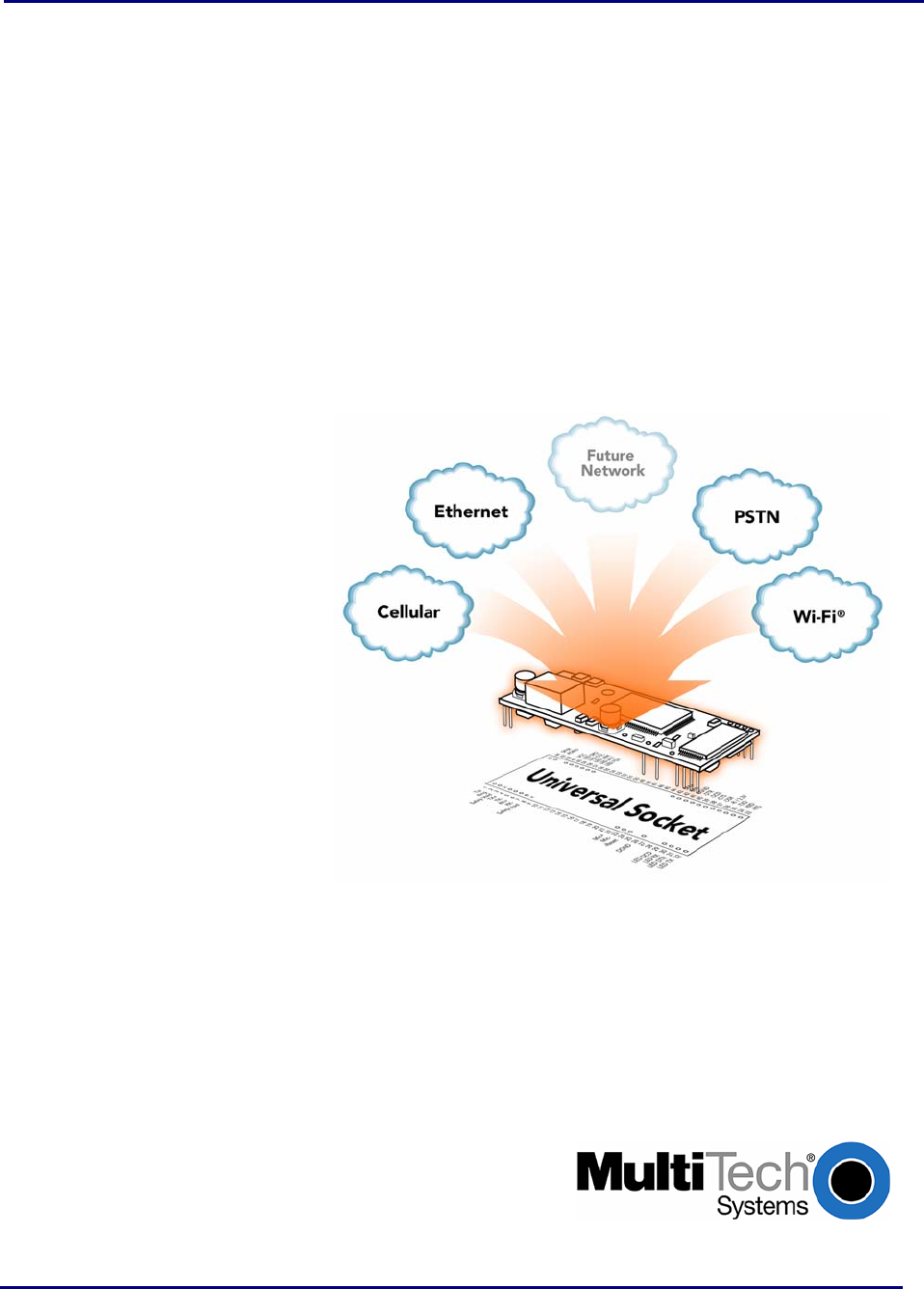
Multi-Tech Embedded Solutions
Multi-Tech’s embedded device networking solutions instantly add communication ability to your existing or new
product with minimal engineering effort giving you an edge on your competition while accelerating your time-to-
market. Our universal socket family of embedded solutions is designed around a flexible comm-port architecture to
provide analog or ISDN dial-up, cellular, Wi-Fi or Bluetooth wireless, or Ethernet socket connectivity with
interchangeable modules. This means you can utilize one system design and populate it with your preferred
connectivity option giving you flexibility and a seamless migration path to future technologies.
Universal Socket Connectivity Features
• Flexible comm-port architecture
• Interchangeable socket modules
• Cost-effective system design
• Easy migration to future technologies
• Complete global compliance
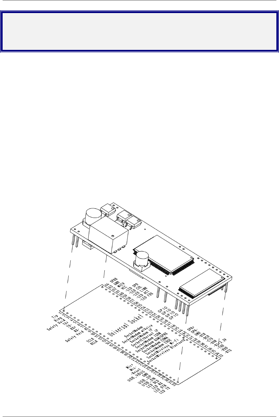
The Universal Socket Design
Each pin on a SocketModem corresponds to a particular function. The universal socket design provides a
universal location for each function pin. This allows each SocketModem to be used in a common board.

Chapter 1 – Universal Socket Connectivity
Multi-Tech Systems, Inc. Universal Socket Hardware Guide for Developers (S000342G) 4
Universal Developer Kit Contents
All products covered in this document can be evaluated using the MTSMI-UDK (Universal Developer Kit).
• One MTSMI-UDK Developer Board
• One 100-240V 9V-1A power supply w/IEC-320 connector
• One IEC-320 power cord w/US type plug
• One IEC-320 power cord w/EURO type plug
• One IEC-320 power cord w/UK type plug
• One RJ-45 cable (CARJ45NK-RJ45 7’8C non-keyed)
• One 7 foot RJ-11 cable plug - plug/4C
• One SMA jack to MMCX plug antenna cable (for CDMA and GPRS antennas)
• One RSMA jack to MMCX plug antenna cable (for Bluetooth antenna)
• One antenna 850/1900, right angle, 3-stripe (for CDMA and GPRS modules)
• One antenna 900/1800, right angle 4-stripe (for GPRS modules)
• One 2.4GHz ½ WAVE antenna with reverse polarity (for SocketWireless Bluetooth and SocketWireless
Wi-Fi)
• One DB9F-DB25M 6 foot modem serial cable
• One generic CDMA Activation Notice
• One Verizon Activation Notice
• One Spring Activation Notice
• One Cingular Activation Notice
• One Universal Socket Connectivity Developer CD with BVRP Mobile PhoneTools
• One Promo Screwdriver
AT Commands Are Included on the Developer CD
AT Commands
Multi-Tech provides Reference Guides for each SocketModem's AT commands, fax commands, and
voice commands. These reference guides are available on the CD included in the Developer Kit. They
are also available by email at mailto:oemsales@multitech.com or by using the Developer Guide
Request Form on Multi-Tech's Web site.
Fax Commands
Fax Commands are included in the AT Command Reference Guide when applicable to the product.
They are available on the CD included in the Developer Kit.
Note: Fax Commands supported by product:
• SocketModem MT5600SMI supports Class 1 & 1.0
• SocketModem MT5656SMI supports Class 1 & 2 (not 2.0/2.1)
• SocketModem MT9234SMI supports all Class 1 and Class 2 commands (Class 1, 1.0, 2, 2.0/2.1)
• SocketModem MT5634SMI supports all Class 1 and Class 2 commands (Class 1, 1.0, 2, 2.0/2.1)
• Wireless SocketModem GPRS MTSMC-G supports Class 1 core commands only (defined by
ITU T.31)
• Wireless SocketModem CDMA MTSMC-C supports Class 2.0 Group 3
• Wireless SocketModem EDGE MTSMC-E supports Class 1 Group 3
• Wireless SocketModem HSDPA MTSMC-H supports Class 1 Group 3

Chapter 1 – Universal Socket Connectivity
Multi-Tech Systems, Inc. Universal Socket Hardware Guide for Developers (S000342G) 5
Design Considerations
Noise Suppression Design Considerations
Engineering noise-suppression practices must be adhered to when designing a printed circuit board (PCB)
containing the SocketModem module. Suppression of noise is essential to the proper operation and
performance of the modem itself and for surrounding equipment.
Two aspects of noise in an OEM board design containing the SocketModem must be considered: on-
board/off-board generated noise that can affect digital signal processing. Both on-board and off-board
generated noise that is coupled on-board can affect interface signal levels and quality. Of particular concern
is noise in frequency ranges affecting modem performance.
On-board generated electromagnetic interference (EMI) noise that can be radiated or conducted off-board is
a separate, but equally important, concern. This type of noise can affect the operation of surrounding
equipment. Most local government agencies have stringent certification requirements that must be met for
use in specific environments.
Proper PC board layout (component placement, signal routing, trace thickness and geometry, etc.)
component selection (composition, value, and tolerance), interface connections, and shielding are required
for the board design to achieve desired modem performance and to attain EMI certification.
Other aspects of proper noise-suppression engineering practices are beyond the scope of this designer
guide. The designer should consult noise suppression techniques described in technical publications and
journals, electronics and electrical engineering text books, and component supplier application notes.
PC Board Layout Guidelines
In a 4-layer design, provide adequate ground plane covering the entire board. In 4-layer designs, power and
ground are typically on the inner layers. All power and ground traces should be 0.05 inches wide.
The recommended hole size for the SocketModem pins is 0.036 in. +/-0.003 in. in diameter. Spacers can be
used to hold the SocketModem vertically in place during the wave solder process. A spacer should be
placed on pin 32 and pin 64 of the SocketModem. A suggested part number for the spacer is BIVAR 938-
0.130 for P1 (0.310in) option SocketModems. The spacers can be left on permanently and will not effect
operation.
All creepages and clearances for the SocketModem have been designed to meet requirements of safety
standards EN60950 or EN60601. The requirements are based on a working voltage of 125V or 250V. When
the recommended DAA* circuit interface is implemented in a third party design, all creepage and clearance
requirements must be strictly followed in order to meet safety standards. The third party safety design must
be evaluated by the appropriate national agency per the required specification.
User accessible areas: Based on where the third party design is to be marketed, sold, or used, it may be
necessary to provide an insulating cover over all TNV exposed areas. Consult with the recognized safety
agency to determine the requirements.
Note: Even if the recommended design considerations are followed, there are no guarantees that a
particular system will comply with all the necessary regulatory requirements. It is imperative that specific
designs be completely evaluated by a qualified/recognized agency.
*DAA stands for Data Access Arrangement. DAA is the telephone line interface of the module.

Chapter 1 – Universal Socket Connectivity
Multi-Tech Systems, Inc. Universal Socket Hardware Guide for Developers (S000342G) 6
Electromagnetic Interference (EMI) Considerations
The following guidelines are offered to specifically help minimize EMI generation. Some of these guidelines
are the same as, or similar to, the general guidelines but are mentioned again to reinforce their importance.
In order to minimize the contribution of the SocketModem-based design to EMI, the designer must
understand the major sources of EMI and how to reduce them to acceptable levels.
1. Keep traces carrying high frequency signals as short as possible.
2. Provide a good ground plane or grid. In some cases, a multilayer board may be required with full
layers for ground and power distribution.
3. Decouple power from ground with decoupling capacitors as close to the SocketModem module
power pins as possible.
4. Eliminate ground loops, which are unexpected current return paths to the power source and
ground.
5. Decouple the telephone line cables at the telephone line jacks. Typically, use a combination of
series inductors, common mode chokes, and shunt capacitors. Methods to decouple telephone
lines are similar to decoupling power lines; however, telephone line decoupling may be more
difficult and deserves additional attention. A commonly used design aid is to place footprints for
these components and populate as necessary during performance/EMI testing and certification.
6. Decouple the power cord at the power cord interface with decoupling capacitors. Methods to
decouple power lines are similar to decoupling telephone lines.
7. Locate high frequency circuits in a separate area to minimize capacitive coupling to other circuits.
8. Locate cables and connectors so as to avoid coupling from high frequency circuits.
9. Lay out the highest frequency signal traces next to the ground grid.
10. If a multilayer board design is used, make no cuts in the ground or power planes and be sure the
ground plane covers all traces.
11. Minimize the number of through-hole connections on traces carrying high frequency signals.
12. Avoid right angle turns on high frequency traces. Forty-five degree corners are good; however,
radius turns are better.
13. On 2-layer boards with no ground grid, provide a shadow ground trace on the opposite side of the
board to traces carrying high frequency signals. This will be effective as a high frequency ground
return if it is three times the width of the signal traces.
14. Distribute high frequency signals continuously on a single trace rather than several traces radiating
from one point.
Electrostatic Discharge Control
All electronic devices should be handled with certain precautions to avoid damage due to the accumulation
of static charge.
See the ANSI/ESD Association Standard (ANSI/ESD S20.20-1999) – a document “for the Development of
an Electrostatic Discharge Control for Protection of Electrical and Electronic Parts, Assemblies and
Equipment.” This document covers ESD Control Program Administrative Requirements, ESD Training, ESD
Control Program Plan Technical Requirements (grounding/bonding systems, personnel grooming, protected
areas, packaging, marking, equipment, and handling), and Sensitivity Testing.
Multi-Tech Systems, Inc. strives to follow all of these recommendations. Input protection circuitry has been
incorporated into the Multi-Tech devices to minimize the effect of this static buildup, proper precautions
should be taken to avoid exposure to electrostatic discharge during handling.
Multi-Tech uses and recommends that others use anti-static boxes that create a faraday cage (packaging
designed to exclude electromagnetic fields). Multi-Tech recommends that you use our packaging when
returning a product and when you ship your products to your customers.
Chapter 1 – Universal Socket Connectivity
Multi-Tech Systems, Inc. Universal Socket Hardware Guide for Developers (S000342G) 7
Mechanicals and Schematics
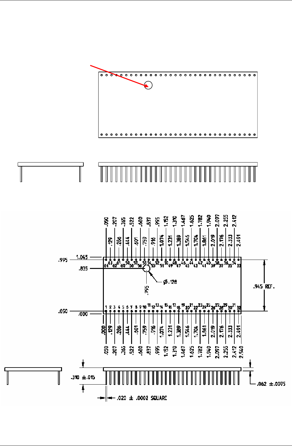
Mechanical Dimensions in Inches
Note: This tooling hole is not on all models.
1
2
3
4
5
67 89
10
11
12
13
14
15
16 17 18 19
20
21
22
23
24
25
26 27 28 29
30
31
32
64
63
62
61
60
59 58 57 56
55
54
53
52
51
50
49 48 47 46
45
44
43
42
41
40
39 38 37 36
35
34
33
Dimensions Are Shown in Inches
Chapter 1 – Universal Socket Connectivity
Multi-Tech Systems, Inc. Universal Socket Hardware Guide for Developers (S000342G) 8
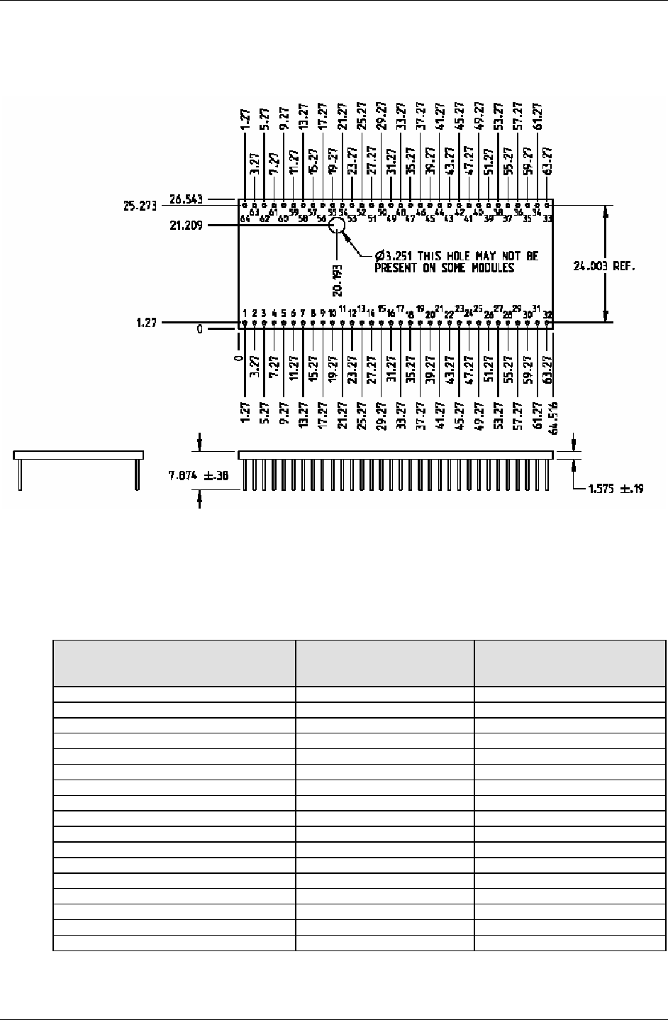
Mechanical Dimensions in Millimeters
Dimensions Are Shown in Millimeters
Maximum Component Height
Product Measurement from top of
board to highest topside
component
Measurement from bottom of
board to lowest bottom-side
component
SocketModem – MT5600SMI .110 inches (2.794 mm) .110 inches (2.794 mm)
SocketModem – MT5656SMI .212 inches (5.384 mm) .110 inches (2.794 mm)
SocketModem – MT5634SMI .290 inches (7.366 mm) .114 inches (2.895 mm)
SocketModem – MT9234SMI .290 inches (7.366 mm) .114 inches (2.895 mm)
SocketModem – MT2492SMI .177 inches (4.495 mm) NA
SocketModem – MT2456SMI .212 inches (5.384 mm) .110 inches (2.794 mm)
SocketModem IP – MT2456SMI-IP .228 inches (5.791 mm) .114 inches (2.895 mm)
SocketModem IP – MT5656SMI-IP .212 inches (5.384 mm) .110 inches (2.794 mm)
SocketEthernet IP – MTXCSEM .315 inches (8.001 mm) .075 inches (1.905 mm)
SocketEthernet IP – MT100SEM .341 inches (8.661 mm) .110 inches (2.794 mm)
SocketModem ISDN – MT128SMI .299 Inches (7.594 mm) .069 inches (1.752 mm)
SocketModem GPRS – MTSMC-G .153 inches (3.886 mm) .118 inches (2.997 mm)
SocketModem CDMA – MTSMC-C .238 inches (6.045 mm) .118 inches (2.997 mm)
SocketModem EDGE – MTSMC-E .253 inches (6.426 mm) .118 inches (2.997 mm)
SocketModem HSDPA – MTSMC-H .253 inches (6.426 mm) .118 inches (2.997 mm)
SocketWireless Wi-Fi – MT800SWM .202 inches (5.130 mm) NA
SocketWireless Bluetooth – MTS2BTSMI .089 inches (2.260 mm) NA
Chapter 2 – SocketModem HSDPA
Multi-Tech Systems, Inc. Universal Socket Hardware Guide for Developers (S000342G) 9
Antenna System for Embedded GSM and CDMA Modems
The antenna system for use with Multi-Tech GSM or CDMA modems includes a coax cable to interface between UFL or
MMCX connection on the modem and the antenna.
RF Specifications
GSM/EGSM RF Specifications
GSM 850 EGSM 900 GSM 1800 GSM 1900
Frequency RX 869 to 894 MHz 925 to 960 MHz 1805 to 1880 MHz 1930 to 1990 MHz
Frequency TX 824 to 849 MHz 880 to 915 MHz 1710 to 1785 MHz 1850 to 1910 MHz
RF Power Stand 2W at 12.5% duty cycle 2W at 12.5% duty cycle 1W at 12.5% duty cycle 1W at 12.5% duty cycle
CDMA RF Specifications
CDMA 800 CDMA 1900
Frequency RX 869 to 894 MHz 1930 to 1990 MHz
Frequency TX 824 to 849 MHz 1850 to 1910 MHz
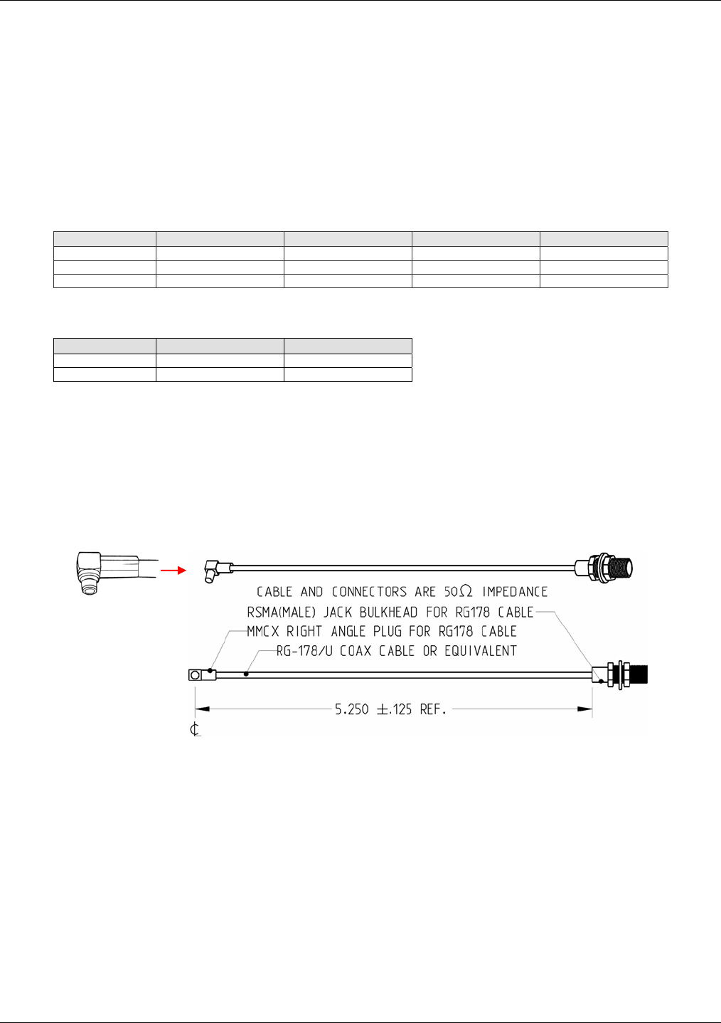
Coax Cable
An optional 6” antenna cable (SMA Jack to MMCX Plug) can be ordered from Multi-Tech Systems, Inc.
Part Number Description
CASMA-MMCX-1 SMA to MMCX COAX RF 6 inch cable (Single Pack)
CASMA-MMCX-10 SMA to MMCX COAX RF 6 inch cable (Ten Pack)
MMCX Plug
Cable Specifications
Cable Type: G-178/u
Attentuation: <1.0db
Connector Impedance: 50 ohm

Chapter 2 – SocketModem HSDPA
Multi-Tech Systems, Inc. Universal Socket Hardware Guide for Developers (S000342G) 10
Connector
An antenna with an SMA connector may be directly connected to a SocketModem GPRS/CDMA through a mating
MMCX to SMA adapter.
MMCX / SMA Connector Available from Amphenol
Amphenol
http://www.amphenol.com/
Order No: 908-31100
Antenna
GSM/EGSM Antenna Requirements/Specifications
Frequency Range: 2.4 to 2.5 GHz
Impedance: 50 ohm
VSWR: <2.0:1
Typical Radiated Gain: 0 dBi on azimuth plane
Radiation: Omni
Polarization: Vertical
Wave: Half Wave Dipole
Antennas Available from Multi-Tech:
Description Part Number
Hinged Right Angle 900/1800 MHz Cellular Modem Antenna ANF1-1HRA
Hinged Right Angle 800/1900 MHz Cellular Modem Antenna ANCF2-1HRA
PTCRB Requirements Note:
There cannot be any alteration to the authorized antenna system. The antenna system must be the same type
with similar in-band and out-of-band radiation patterns and maintain the same specifications.

Chapter 2 – SocketModem HSDPA
Multi-Tech Systems, Inc. Universal Socket Hardware Guide for Developers (S000342G) 11
Safety Notices and Warnings
Note to OEMs: The following safety statements may be used in the documentation of your final product
applications.
Telecom Safety Warning
1. Never install telephone wiring during a lightning storm.
2. Never install a telephone jack in wet locations unless the jack is specifically designed for wet locations.
3. This product is to be used with UL and cUL listed computers.
4. Never touch uninsulated telephone wires or terminals unless the telephone line has been disconnected at the
network interface.
5. Use caution when installing or modifying telephone lines.
6. Avoid using a telephone during an electrical storm. There may be a remote risk of electrical shock from lightning.
7. Do not use a telephone in the vicinity of a gas leak.
8. To reduce the risk of fire, use only 26 AWG or larger telecommunication line cord.
9. This product must be disconnected from its power source and telephone network interface when servicing.
Wireless Safety
General Safety
The modem is designed for and intended to be used in fixed and mobile applications. “Fixed” means that the
device is physically secured at one location and is not able to be easily moved to another location. “Mobile”
means that the device is designed to be used in other than fixed locations.
Caution: Maintain a separation distance of at least 20 cm (8 inches) is normally
maintained between the transmitter’s antenna and the body of the user or nearby persons.
The Modem is not designed for or intended to be used in portable applications within 20
cm. (8 inches) of the body of the user.
RF Interference Issues
It is important to follow any special regulations regarding the use of radio equipment due in particular to the
possibility of radio frequency, RF, interference. Please follow the safety advice given below carefully.
• Switch OFF your Wireless MultiModem when in an aircraft. The use of cellular telephones in an aircraft
may endanger the operation of the aircraft, disrupt the cellular network and is illegal. Failure to observe
this instruction may lead to suspension or denial of cellular telephone services to the offender, or legal
action or both.
• Switch OFF your Wireless MultiModem when around gasoline or diesel-fuel pumps and before filling your
vehicle with fuel.
• Switch OFF your Wireless MultiModem in hospitals and any other place where medical equipment may be
in use.
• Respect restrictions on the use of radio equipment in fuel depots, chemical plants or where blasting
operations are in progress.
• There may be a hazard associated with the operation of your Wireless MultiModem close to inadequately
protected personal medical devices such as hearing aids and pacemakers. Consult the manufacturers of
the medical device to determine if it is adequately protected.
• Operation of your Wireless MultiModem close to other electronic equipment may also cause interference if
the equipment is inadequately protected. Observe any warning signs and manufacturers’
recommendations.

Chapter 2 – SocketModem HSDPA
Multi-Tech Systems, Inc. Universal Socket Hardware Guide for Developers (S000342G) 12
Vehicle Safety
• Do not use your MultiModem while driving.
• Respect national regulations on the use of cellular telephones in vehicles. Road safety always comes first.
• If incorrectly installed in a vehicle, the operation of Wireless MultiModem telephone could interfere with the
correct functioning of vehicle electronics. To avoid such problems, be sure that qualified personnel have
performed the installation. Verification of the protection of vehicle electronics should be part of the
installation.
• The use of an alert device to operate a vehicle’s lights or horn on public roads is not permitted.
Maintenance of Your Modem
Your Wireless MultiModem is the product of advanced engineering, design, and craftsmanship and should
be treated with care. The suggestions below will help you to enjoy this product for many years.
• Do not expose the Wireless MultiModem to any extreme environment where the temperature is above
50ºC or humidity is above 90% noncondensing.
• Do not attempt to disassemble the Wireless MultiModem. There are no user serviceable parts inside.
• Do not expose the Wireless MultiModem to water, rain, or spilled beverages. It is not waterproof.
• Do not place the Wireless MultiModem alongside computer discs, credit or travel cards, or other magnetic
media. The phone may affect the information contained on discs or cards.
• The use of accessories not authorized by Multi-Tech or not compliant with Multi-Tech's accessory
specifications may invalidate the warranty of the Wireless MultiModem.
• In the unlikely event of a fault in the Wireless MultiModem, contact Multi-Tech Tech Support.
Your Responsibility
This Wireless MultiModem is your responsibility. Please treat it with care respecting all local regulations. It is
not a toy. Therefore, keep it in a safe place at all times and out of the reach of children.
Try to remember your Unlock and PIN codes. Become familiar with and use the security features to block
unauthorized use and theft.
Chapter 2 – SocketModem HSDPA
Multi-Tech Systems, Inc. Universal Socket Hardware Guide for Developers (S000342G) 13
Waste Electrical and Electronic Equipment Statement
Note to OEMs: The statement is included for your information and may be used in the documentation of your
final product applications.
WEEE Directive
The WEEE directive places an obligation on EU-based manufacturers, distributors, retailers, and importers to take-
back electronics products at the end of their useful life. A sister Directive, ROHS (Restriction of Hazardous
Substances) complements the WEEE Directive by banning the presence of specific hazardous substances in the
products at the design phase. The WEEE Directive covers all Multi-Tech products imported into the EU as of August
13, 2005. EU-based manufacturers, distributors, retailers and importers are obliged to finance the costs of recovery
from municipal collection points, reuse, and recycling of specified percentages per the WEEE requirements.
Instructions for Disposal of WEEE by Users in the European Union
The symbol shown below is on the product or on its packaging, which indicates that this product must not be
disposed of with other waste. Instead, it is the user’s responsibility to dispose of their waste equipment by handing it
over to a designated collection point for the recycling of waste electrical and electronic equipment. The separate
collection and recycling of your waste equipment at the time of disposal will help to conserve natural resources and
ensure that it is recycled in a manner that protects human health and the environment. For more information about
where you can drop off your waste equipment for recycling, please contact your local city office, your household
waste disposal service or where you purchased the product.
July, 2005

Chapter 2 – SocketModem HSDPA
Multi-Tech Systems, Inc. Universal Socket Hardware Guide for Developers (S000342G) 14
Restriction of the Use of Hazardous Substances (RoHS)
Multi-Tech Systems, Inc.
Certificate of Compliance
2002/95/EC
Multi-Tech Systems Inc. confirms that MTxxxxSMI, MTSMC-G-F1, MTxxxxSEM, MTIFM, and MTxxxSWM
now comply with the chemical concentration limitations set forth in the directive 2002/95/EC of the European
Parliament (Restriction Of the use of certain Hazardous Substances in electrical and electronic equipment - RoHS)
These Multi-Tech Systems, Inc. products do not contain the following banned chemicals:
Lead, [Pb] > 1000 PPM
Mercury, [Hg] > 1000 PPM
Hexavalent Chromium, [Cr+6] > 1000 PPM
Cadmium, [Cd] > 100 PPM
Polybrominated Biphenyl, [PBB] > 1000 PPM
Polybrominated Diphenyl Ether, [PBDE] > 1000 PPM
Moisture Sensitivity Level (MSL) =1
Tin Whisker Growth = None detected
Maximum Soldering temperature = 260C (wave only)
Notes:
1. Lead usage in some components is exempted by the following RoHS annex; therefore, higher lead
concentration would be found in some modules (>1000ppm).
a. Lead in high melting temperature type solders (i.e., tin-lead solder alloys containing more than 85%
lead).
b. Lead in electronic ceramic parts (e.g., piezoelectronic devices).
2. Moisture Sensitivity Level (MSL) – Analysis is based on the components/material used on the board.
3. Tin Whisker Study was done per NEMI guidelines (Elevated temperature cycle of 60°C and non-condensing
relative humidity of 87% exposed to this environment for 1000 hours).
Chapter 2 – SocketModem HSDPA
Multi-Tech Systems, Inc. Universal Socket Hardware Guide for Developers (S000342G) 15
Chapter 2 – SocketModem HSDPA
Introduction
The Multi-Tech SocketModem HSDPA embedded wireless modem delivers some of the fastest cellular data speeds by
utilizing HSDPA technology. It allows users to connect to the Internet and send and receive data faster than possible with an
ordinary GSM/GPRS network making it ideal for highly data-intensive applications. Based on industry-standard open
interfaces, the SocketModem wireless modem is equipped with quad-band, high-speed RS232 technology, which means it can
be used worldwide on all existing GSM networks. In addition, it utilizes Multi-Tech's universal socket design.
Product Ordering Information
Product Description Region Order This
Product
3
MTSMC-H SocketModem Quad Band HSPDA Class 10 – 5V Global
MTSMC-H-U SocketModem Quad Band HSPDA Class 10 w/USB Global
MTSMI-UDK Universal Developer Kit Global
How to Read the Product Codes in the Table Above:
H HSDPA (High-Speed Downlink Packet Access)
U USB
UDK Universal Developer Kit
Other Product Codes:
The complete product code will end in .Rx. For example, MTSMC-H.Rx.
“R” indicates product revision. “x” is the revision number.

Chapter 2 – SocketModem HSDPA
Multi-Tech Systems, Inc. Universal Socket Hardware Guide for Developers (S000342G) 16
Technical Specifications
Category Description
Standards: GSM Class Small MS
GSM / GPRS / EGPRS
Data Transfer GPRS
• Multislot Class 10
• Full PBCCH support
• Mobile Station Class B
• Coding Scheme 1 – 4
EGPRS
• EDGE E2 power class for 8 PSK
• Downlink coding schemes – CS 1-4, MCS 1-9
• Uplink coding schemes – CS 1-4, MCS 1-9
• BEP reporting
• SRB loopback and test mode B
• 8-bit, 11-bit RACH
• PBCCH support
• 1 phase/2 phase access procedures
• Link adaptation and IR
• NACC, extended UL TBF
• Mobile Station Class B
CSD
• V.110, RLP, non-transparent
• 9.6 kbps
UMTS Data Rate (Release
99, June 2004, W-CDMA
FDD standard)
PS data rate – 384 kbps DL / 384 kbps UL CS data rate – 64 kbps DL / 64 kbps UL
Bandwidth • UMTS/HSDPA: Single band, 2100MHz
• GSM/GPRS/EDGE: Dual band, 900/1800MHz
• UMTS/HSDPA: Triple band, 850//1900/2100MHz
• GSM/GPRS/EDGE: Quad band, 850/900/1800/1900MHz
Connectors Antenna: MMCX
SIM: Standard 3V SIM receptacle
Operating Voltage (Power
Supply) 5V
Output power (according
to Release 99) Class 4 (+33dBm ±2dB) for EGSM850
Class 4 (+33dBm ±2dB) for EGSM900
Class 1 (+30dBm ±2dB) for GSM1800
Class 1 (+30dBm ±2dB) for GSM1900
Class E2 (+27dBm ± 3dB) for GSM 850 8-PSK
Class E2 (+27dBm ± 3dB) for GSM 900 8-PSK
Class E2 (+26dBm +3 /-4dB) for GSM 1800 8-PSK
Class E2 (+26dBm +3 /-4dB) for GSM 1900 8-PSK
Class 3 (+24dBm +1/-3dB) for UMTS 2100, WCDMA FDD BdI
Class 3 (+24dBm +1/-3dB) for UMTS 1900,WCDMA FDD BdII
Class 3 (+24dBm +1/-3dB) for UMTS 850, WCDMA FDD BdV
Operating Temperatures Min -30 °C Typ +25 °C Max +75
Storage Environment -40° to +85° C
Humidity 20% to 90% non-condensing
Dimensions 2.55” L x 1.4” W x 0.563” H (6.48 cm x 3.5 cm x 1.43 cm)
Weight 1 oz. (0.028 kg.)
Certifications & Approvals Certifications:
CE Mark
Safety Certifications:
UL 60950
cUL 60950
EN 60950
AS/NZS 60950:2000
EMC Approvals:
FCC Part 2, 15, 22, 24
EN 55022
EN 55024
Network:
PTCRB
Chapter 2 – SocketModem HSDPA
Multi-Tech Systems, Inc. Universal Socket Hardware Guide for Developers (S000342G) 17
Warranty 2 years
Intelligent Features SMS – Text & PDU, Point-to-Point, cell broadcast
AT Command Compatible
Voice features include Half Rate (HR), Full Rate (FR), Enhanced Full Rate (EFR), Adaptive
multi rate (AMR), as well as hands free echo cancellation, and noise reduction
Embedded TCP/IP protocol stack brings Internet connectivity
Audio
Audio speech codecs
• GSM: AMR, EFR, FR, HR
• 3GPP: AMR-WB
• 3GPP2: EVRC, EVRC-B (4GV-WB/NB)
• Diverse: G.711 vocoder
• One ringing melody supported
• CEPT supervisory tones supported
• DTMF supported
Other
• Handset, Headset, Speakerphone and Transparent mode
• TTY support selecting a dedicated audio mode
• Download of audio parameters
• Gains and volumes can be controlled by AT commands
• Several additional ringing melodies
• CEPT and ANSI supervisory tones supported
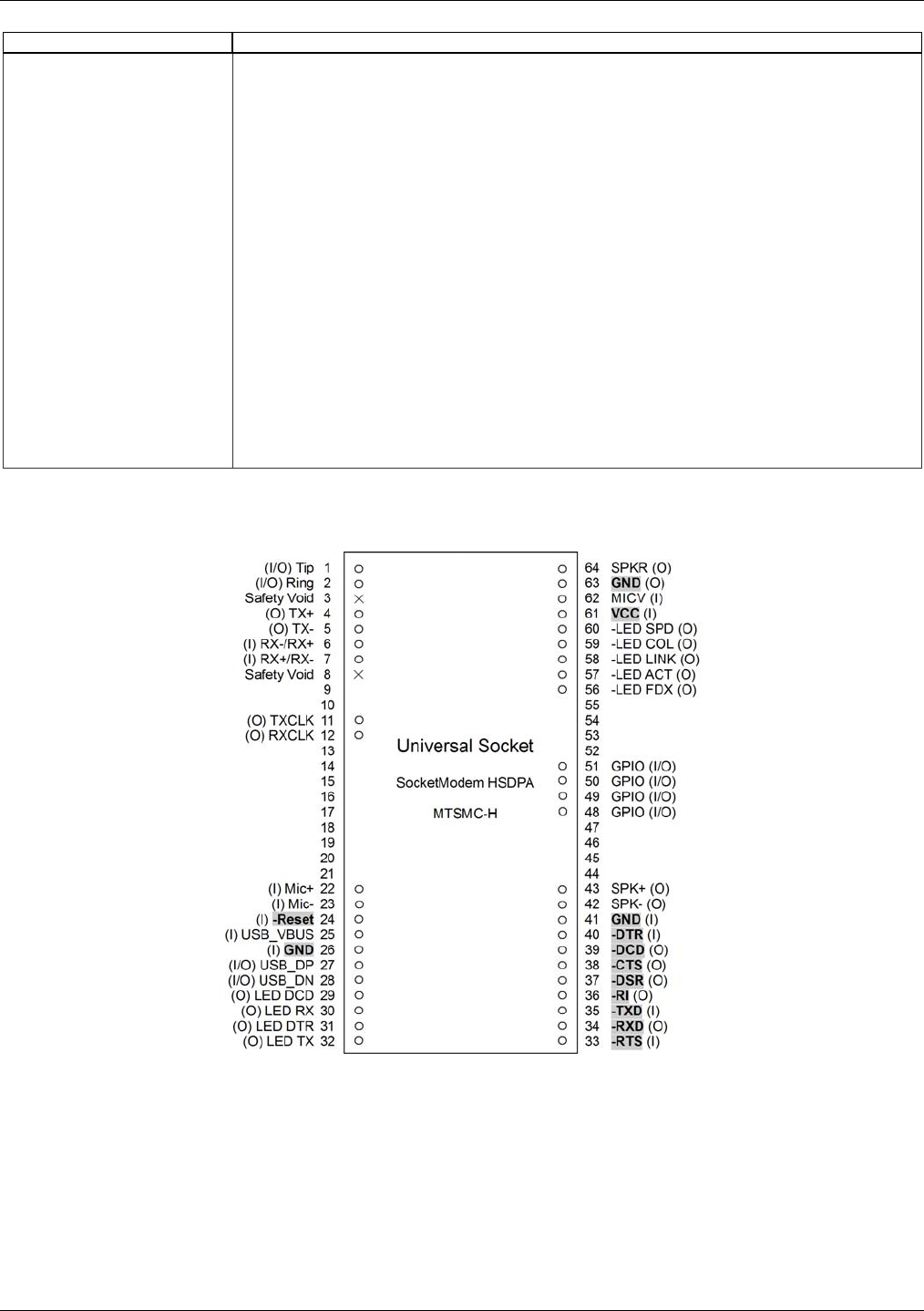
Pin Configurations
Top View
SocketModem HSDPA Pinout
For pin descriptions, see the Universal Pinout Descriptions in Chapter 1.
Chapter 2 – SocketModem HSDPA
Multi-Tech Systems, Inc. Universal Socket Hardware Guide for Developers (S000342G) 18
HSPDA Electrical Characteristics
I/O Electrical Characteristics
5VDC Characteristics (VDD = 5V ± 0.25V) VDDMAX = 5.25V
Digital Inputs
–DTR (40), –TXD (35), –RTS (33) Input High
Min 2.0V Input Low
Max 0.8V
–RESET Input High
Min 2.6V Input Low
Max 1.0V
Digital Outputs
–DCD (39), –CTS (38), –DSR (37), –RI (36), –RXD (34) Output High
Min 4V Output Low
Max 0.4V Current Drive
2mA
Digital Input Capacitance 5 pF
HSPDA Power Consumption
Voice Mode Power Consumption
GSM Call Power Consumption in EGSM900 and GSM850 @ 25 degrees C
Voltage Conditions INOM IMAX
+5V During TX bursts @ 2W 1.2 A 2.0 A
+5V Average @ 2W 250mA 335mA
+5V Average idle mode 28mA 35mA
GSM Call Power Consumption in GSM1800 & 1900 MHz @ 25 degrees C
Voltage Conditions INOM IMAX
+5V During TX bursts @ 1W 1.1 A 1.6 A
+5V Average @1W 210mA 285mA
+5V Average idle mode 28mA 35mA
Data Mode Power Consumption
GPRS Class 10 Power Consumption in EGSM/GPRS 900 MHz and GSM/GRPS 850 MHz
Voltage Conditions INOM IMAX
+5V During TX bursts @ 2W 1.5 A 2.0 A
+5V Average @ 2W 400mA 610mA
+5V Average @ 1W 280mA 488mA
+5V Average idle mode 28mA 35mA
GPRS Class 10 Power Consumption in GSM/GRPS 1800 MHz and GSM/GRPS 1900 MHz
Voltage Conditions INOM IMAX
+5V During TX bursts @ 1W 1.1 A peak 1.2 A peak
+5V Average @ 1W 350mA 510mA
+5V Average @ .25W 180mA 460mA
+5V Average idle mode 28mA 35mA
EGPRS Class 10 Power Consumption in EGRPS 900 MHz and EGRPS 850 MHz
Voltage Conditions INOM IMAX
+5V During TX bursts @ 5W 1.4 A peak 1.6 A peak
+5V Average @ .5W 430mA 525mA
+5V Average @ .25W 375mA 450mA
+5V Average idle mode 28mA 35mA

Chapter 2 – SocketModem HSDPA
Multi-Tech Systems, Inc. Universal Socket Hardware Guide for Developers (S000342G) 19
Application Notes
Radio Characteristics
GSM 850 EGSM 900 GSM 1800 GSM 1900
Frequency RX 869 to 894 MHz 925 to 960 MHz 1805 to 1880 MHz 1930 to 1990 MHz
Frequency TX 824 to 849 MHz 880 to 915 MHz 1710 to 1785 MHz 1850 to 1910 MHz
RF Power Stand 2W at 12.5%
duty cycle
2W at 12.5% duty
cycle
1W at 12.5% duty
cycle
1W at 12.5% duty
cycle
Impedance 50 ohms
VSWR <2
Typical Radiated Gain 0 dBi on azimuth plane
Receiver Features
• EGSM Sensitivity : < -108 dBm
• GSM 1800/GSM 1900 Sensitivity : < -107 dBm
• Selectivity @ 200 kHz : > +9 dBc
• Selectivity @ 400 kHz : > +41 dBc
• Dynamic range : 62 dB
• Intermodulation : > -43 dBm
• Co-channel rejection : + 9 dBc
Transmitter Features
• Maximum output power (EGSM) : 24 dBm +/- 2 dB
• Maximum output power (DCS/PCS) : 30 dBm +/- 2 dB
• Minimum output power (EGSM): 5 dBm +/- 5 dB
• Minimum output power (DCS/PCS): 0 dBm +/- 5 dB
• H2 level : < -30 dBm
• H3 level : < -30 dBm
• Noise in 925 - 935 MHz : < -67 dBm
• Noise in 935 - 960 MHz : < -79 dBm
• Noise in 1805 - 1880 MHz : < -71 dBm
• Phase error at peak power : < 5 ° RMS
• Frequency error : +/- 0.1 ppm max
Audio Interface – Electrical Characteristics
Speaker Output
Differential speaker output capable of driving 8 ohm load. 1.0945 Vpp (differential) typical.
Microphone Input
Balanced microphone input: full scale input 1.1 Vpp.
Chapter 2 – SocketModem HSDPA
Multi-Tech Systems, Inc. Universal Socket Hardware Guide for Developers (S000342G) 20
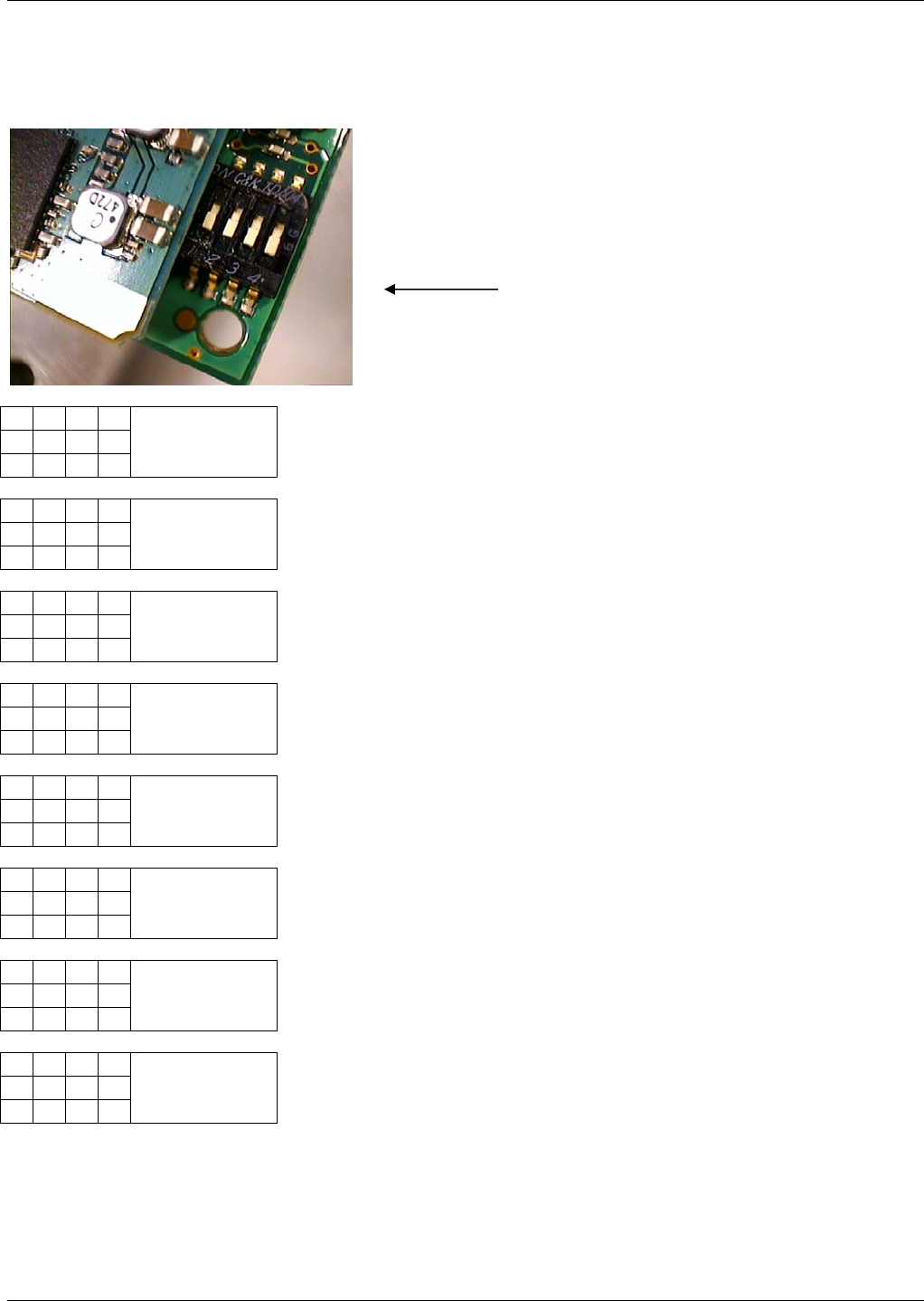
Baud Rate Switches on the HSDPA SocketModem
MTSMC-H SocketModem Baud Rate dip switch settings
● ● ● ●
1 2 3 4
920K
●
● ● ●
1 2 3 4
460K
●
● ● ●
1 2 3 4
230K
● ●
● ●
1 2 3 4
115K
●
● ● ●
1 2 3 4
57.6K
● ●
● ●
1 2 3 4
38.4K
● ●
● ●
1 2 3 4
19.2K
● ● ●
●
1 2 3 4
9.6K
Switch Bank

Chapter 2 – SocketModem HSDPA
Multi-Tech Systems, Inc. Universal Socket Hardware Guide for Developers (S000342G) 21
Operating Modes
The table below briefly summarizes the various operating modes.
Mode Function
GSM / GPRS / UMTS /
HSDPA SLEEP
Power saving mode set automatically when no call is in progress and the
USB connection is suspended by host or not present.
GSM IDLE Software is active. Once registered to the GSM network, paging with BTS is
carried out in order to achieve synchrony with the GSM network. The
repetition rate depends on the parameter BSPA_Multiframe. The module is
ready to send and receive.
GSM TALK Connection between two subscribers is in progress. Power consumption
depends on the GSM network coverage and several connection settings
(e.g. DTX off/on, FR/EFR/HR, hopping sequences and antenna connection).
The following applies when power is to be measured in TALK_GSM mode:
DTX off, FR and no frequency hopping, otherwise same as for IDLE
measurements.
Normal
operation
GPRS IDLE Module is attached and ready for GPRS data transfer, but no data is
currently sent or received.
GPRS DATA GPRS data transfer in progress. Power consumption depends on network
settings (e.g. power control level), uplink / downlink data rates and GPRS
configuration (e.g. used multislot settings).
EGPRS DATA EGPRS data transfer in progress. Power consumption depends on network
settings (e.g. power control level), uplink / downlink data rates and EGPRS
configuration (e.g. used multislot settings).
UMTS / HSDPA IDLE Module is attached and ready for UMTS / HSDPA data transfer, but no data
is currently sent or received.
UMTS DATA UMTS data transfer in progress. Power consumption depends on network
settings (e.g. TPC Pattern) and data transfer rate.
HSDPA DATA HSDPA data transfer in progress. Power consumption depends on network
settings (e.g. TPC Pattern) and data transfer rate.

Chapter 2 – SocketModem HSDPA
Multi-Tech Systems, Inc. Universal Socket Hardware Guide for Developers (S000342G) 22
Turn off the Module Using AT Command
The best and safest approach to powering down is to issue the AT^SMSO command. This procedure lets the module log off
from the network and allows the software to enter into a secure state and safe data before disconnecting the power supply.
The mode is referred to as Power-down mode. In this mode, only the RTC stays active.
After sending AT^SMSO do not enter any other AT commands. There are two ways to verify that the module turns off:
Wait for the ”OK” – response. It indicates that data has been stored non-volatile and that the module turns off in less than TBD
second.
Important Note: The SocketModem requires a reset to become active again.
USB Interface
The Module supports a USB 1.1 Full Speed (12Mbit/s) device interface.
The USB I/O-pins are capable of driving the signal at min 3.0V.
To properly connect the module’s USB interface to the host a USB 1.1 compatible connector is required. Furthermore, the
USB modem driver for Windows XP delivered with the module be installed as described in the Installation Guide.
While the USB connection is active, the module will not change into SLEEP Mode. To enable switching into SLEEP mode the
USB host has to be able to change into suspend mode. On incoming calls, the module will then generate a remote wake up
request to resume the USB connection. This can be realized by means of the HOST_WAKEUP line. If no call, data or
message transfer is in progress, the HOST_WAKEUP line is passive. To save power, the host could then shut down the USB
interface. If a call or other request (URC’s, messages) arrives, the host can be woken up again by activation of
HOST_WAKEUP (passive to active transition).
Analog Audio Interface
The module supports one analog audio interface available on the board to board connector.
The following two pictures show the balanced headset interface with microphone feeding and the line interface.
Network Connectivity Status Signals
One status signal is provided for signaling the module’s connectivity status (58 of the socket).