Multi Tech Systems 92U09D24824 SocketModem GSM User Manual
Multi Tech Systems Inc SocketModem GSM
UserManual.wiki
>
Multi Tech Systems
>
92U09D24824 User Manual
>
User Manual
Contents
1.
User Manual
2.
User Guide
User Manual
Navigation menu
Upload a User Manual
Namespaces
Wiki Guide
HTML
PDF
Info
Views
User Manual
Discussion / Help
Navigation

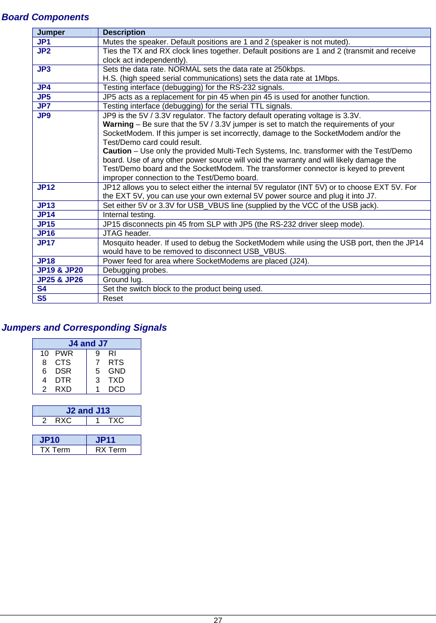
![5 Technical Specifications The MTSMC-G2 and MTSMC-G2-IP SocketModems meet the following specifications: Category Description Standards GPRS Class 10 Frequency Bands Quad-band GSM/EGPRS 850/900/1800/1900 MHz Serial/Data Speed Serial interface supports DTE speeds up to 921.6K IP interface supports DTE speeds at the fixed rate of 115.2 Packet data up to 85.6K bps Circuit-switched data (GPRS) up to 14.4K bps transparent and non-transparent Supports data rates of 921600, 460800, 230400, 115200 bps Data Format 10 bit Serial Asynchronous Data Error Correction MNP2 Data Compression V.42bis Weight 1 oz. (28 g) Size 3.15" x 1.375" (80.010 mm x 34.925 mm) Operating Temperature -40° C to +85° C Storage Temperature -40 °C to +85°C Humidity 10% to 90% Input Power 5VDC Operating Voltage Supply Range: VCC Maximum: 5.5 Voltage at Any Signal Pin Minimum: GND Maximum: VCC Antenna Connector Surface mount UFL SIM Holder Standard 3V SIM holder IP Protocols Supported MTSMC-G2 DNS Resolve, FTP client, LCP, PPP (dial-out),TCP socket, UDP socket, PAP & CHAP authentication MTSMC-G2-IP DNS Resolve, FTP client, Ping, POP3 client, PPP (dial-out), SMTP, TCP RAW client & server, UDP RAW client & server, PAP & CHAP authentication M2M Applications MTSMC-G2-IP Automatic connect/reconnect, device monitor, modem emulation, Ping & TCP keep alive, wake-up on caller ID, wake-up on ring Compliance EMC Compliance FCC Part 15 EN55022 EN55024 Radio Compliance FCC Part 22 FCC Part 24 RSS 132 RSS 133 EN 301 511 EN 301 489-1 EN 301 489-7 AS/ACIF S042.1 AS/ACIF S042.3 Safety Compliance UL 60950-1 cUL 60950-1 EN 60950-1 AS/NZS 60950-1 Network Compliance PTCRB GCF Warranty Two years Comment [DAR1]: From Dustin 6/24/09 Comment [DAR2]: From Dustin 6/24/09](https://usermanual.wiki/Multi-Tech-Systems/92U09D24824.User-Manual/User-Guide-1151646-Page-5.png)
![6 Specifications Continued: Category Description Features Modes of Operation: Data Mode, Command Mode, and Voice Mode Embedded TCP/IP stack Short Message Services (SMS) RTS/CTS hardware flow control AT command compatible Support for HR, FR, EFR, and AMR (Adaptive Multi Rate) voice codec support Flash upgradeable Non-volatile memory Electrical Characteristics Units: Volts 5V DC Characteristics (VDD = 5V ± 0.25V) VDDMAX = 5.25V Parameter Minimum Maximum Digital Signal Input Low Level –DTR (40), –TXD (35), –RTS (33) GND 0.8 Digital Signal Input High Level –DTR (40), –TXD (35), –RTS (33) 2 Vcc Digital Signal Output Low Level –DCD (39), –CTS (38), –DSR (37), –RI (36), –RXD (34) 0.4 Digital Signal Output High Level –DCD (39), –CTS (38), –DSR (37), –RI (36), –RXD (34) 3.84 Reset (Low Active) Input Low Level –Reset (24) 0.8 Reset (Low Active) Input High Level –Reset (24) 2 Digital Input Capacitance 14pF Power Consumption MTSMC-G2 Measured Power* Measures at Input Voltage 5.00 Sleep Typical Maximum Peak Current (AMPS) 0.049 0.113 0.24 1.10 Watts 0.245 0.564 1.195 MTSMC-G2-IP Measured Power* Measures at Input Voltage 5.00 Sleep Typical Maximum Peak Current (AMPS) 0.080 0.135 0.280 1.250 Watts 0.382 0.664 1.358 Note: Current Peak = 1500mA maximum during Tx burst. * Multi-Tech Systems, Inc. recommends that the customer incorporate a 10% buffer into their power source when determining product load. Comment [DAR3]: Measurements for MTSMC-G2-IP 73120965 Rev 0 from Tom Fix. He suggested the current peak text also 4/22/09. He said these measurements apply to G2 without IP, too. Comment [DAR4]: Measurements for MTSMC-G2-IP 73120965 Rev 0 from Tom Fix. He suggested the current peak text also 4/22/09. He said these measurements apply to G2 without IP, too.](https://usermanual.wiki/Multi-Tech-Systems/92U09D24824.User-Manual/User-Guide-1151646-Page-6.png)
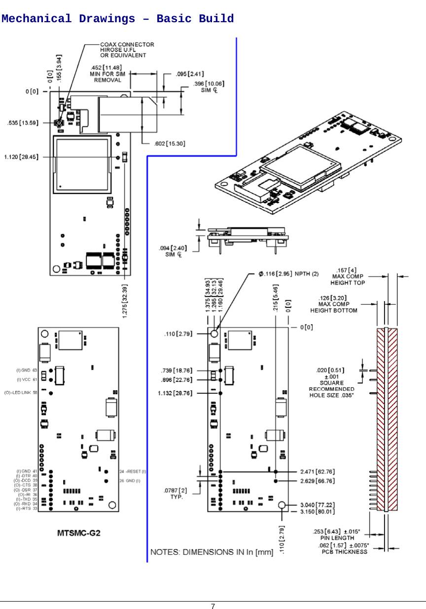
![Application Notes Flashing LED Interface The flashing LED signal is used to indicate the working mode of the SocketModem. LEDs and SocketModem Status Signal SocketModem Status OFF Download mode or switched OFF> Continuously lit Switched ON (not registered on the network) ON Flashing Switched ON (registered on the network) RF Performances RF performances are compliant with the ETSI recommendation 05.05 and 11.10. 10 Note: The following statistics are subject to change due to pending test results. Comment [DAR5]: Tom Hofstedt expects text results in by June 24th. The main parameters are: Receiver Features • EGSM Sensitivity : < -104 dBm • GSM 1800/GSM 1900 Sensitivity : < -102 dBm • Selectivity @ 200 kHz : > +9 dBc • Selectivity @ 400 kHz : > +41 dBc • Dynamic range : 62 dB • Intermodulation : > -43 dBm • Co-channel rejection : + 9 dBc Transmitter Features • Maximum output power (EGSM) : 33 dBm ± 2 dB • Maximum output power (DCS/PCS) : 30 dBm ± 2 dB • Minimum output power (EGSM): 5 dBm ± 5 dB • Minimum output power (DCS/PCS): 0 dBm ± 5 dB • H2 level : < -30 dBm • H3 level : < -30 dBm • Noise in 925 - 935 MHz : < -67 dBm • Noise in 935 - 960 MHz : < -79 dBm • Noise in 1805 - 1880 MHz : < -71 dBm • Phase error at peak power : < 5 ° RMS • Frequency error : ± 0.1 ppm max RF Connection and Antenna The RF connector on the SocketModem GPRS is a UFL standard type. See Chapter 1 for Antenna System details. Microphone Inputs The MIC inputs are differential ones. They already include the convenient biasing for an electret microphone (0.5 mA and 2 Volts). This electret microphone can be directly connected on these inputs. The impedance of the microphone has to be around 2K. These inputs are the standard ones for a handset design. The gain of the MIC inputs is internally adjusted. The gain can be tuned from 30dB to 51dB. The connection to the microphone is direct. MIC2NMIC2PC1C1 = 22pF to 100 pF33 pF recommended](https://usermanual.wiki/Multi-Tech-Systems/92U09D24824.User-Manual/User-Guide-1151646-Page-10.png)

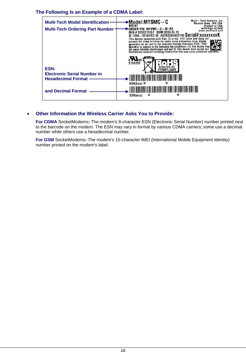
![Wireless Approvals and Labeling Requirements Wireless Approvals (GSM, CDMA) The Multi-Tech SocketModem is Industry and/or Carrier Approved as an End Product modem. In most cases, when integrated and used with an antenna system that was part of the Multi-Tech modem certification, no additional approvals or certification is required (however, CDMA has a few exceptions) for the device you develop as long as the following are met: • PTCRB Requirements: The antenna system cannot be altered. • Model Identification: IMPORTANT When the wireless carrier asks you to provide the modem's model identification, give the Multi-Tech wireless model identification, not the identification of the host device model. See the label example below. The Multi-Tech model identification allows the carrier to verify the modem as one of its approved models. This information is located on the modem's label. The Following Is an Example of an End Product GPRS Label: 17 Host Device Model Identification Multi-Tech SocketModem Model Identification IMEI (International Mobile Equipment Identity) Comment [DAR6]: Label_GPRS_F4.png](https://usermanual.wiki/Multi-Tech-Systems/92U09D24824.User-Manual/User-Guide-1151646-Page-17.png)
![Restriction of the Use of Hazardous Substances (RoHS) Multi-Tech Systems, Inc. Certificate of Compliance 2002/95/EC Multi-Tech Systems Inc. confirms that its embedded products now comply with the chemical concentration limitations set forth in the directive 2002/95/EC of the European Parliament (Restriction Of the use of certain Hazardous Substances in electrical and electronic equipment - RoHS) These Multi-Tech Systems, Inc. products do not contain the following banned chemicals: Lead, [Pb] < 1000 PPM Mercury, [Hg] < 1000 PPM Hexavalent Chromium, [Cr+6] < 1000 PPM Cadmium, [Cd] < 100 PPM Polybrominated Biphenyl, [PBB] < 1000 PPM Polybrominated Diphenyl Ether, [PBDE] < 1000 PPM Moisture Sensitivity Level (MSL) =1 Tin Whisker Growth = None detected Maximum Soldering temperature = 260C (wave only) Notes: 1. Lead usage in some components is exempted by the following RoHS annex; therefore, higher lead concentration would be found in some SocketModems (>1000ppm). a. Lead in high melting temperature type solders (i.e., tin-lead solder alloys containing more than 85% lead). b. Lead in electronic ceramic parts (e.g., piezoelectronic devices). 2. Moisture Sensitivity Level (MSL) – Analysis is based on the components/material used on the board. 3. Tin Whisker Study was done per NEMI guidelines (Elevated temperature cycle of 60°C and non-condensing relative humidity of 87% exposed to this environment for 1000 hours). 23](https://usermanual.wiki/Multi-Tech-Systems/92U09D24824.User-Manual/User-Guide-1151646-Page-23.png)
![26 Chapter 5 – SocketModem Developer Board SocketModem Developer Board This developer board drawing shows the major board components for all SocketModems. Board Revision B See the next page for description of Board Components Comment [DAR7]: C:\Universal_SocketModem \ Graphics_ETC_Rev_I \ Board_B_Schematics \ SchematicsfromJohnM \ Board_B_for_Universal_260b0_forRev J jumper fixed.png](https://usermanual.wiki/Multi-Tech-Systems/92U09D24824.User-Manual/User-Guide-1151646-Page-26.png)
![28 SocketModem Developer Board Block Diagram Comment [DAR8]: Block Diagram 2008.png](https://usermanual.wiki/Multi-Tech-Systems/92U09D24824.User-Manual/User-Guide-1151646-Page-28.png)
![Developer Board Schematics 29 Board Revision B Comment [DAR9]: Schematics Board B page 2 Scan0576_000.jpg did not change to gif – file was already small](https://usermanual.wiki/Multi-Tech-Systems/92U09D24824.User-Manual/User-Guide-1151646-Page-29.png)
![30 Developer Board Schematics Comment [DAR10]: Schematics Board B page 3 Scan0577_000grayscale50percent.gif (changed from jpg to make the file size smaller 8/5/09) Board Revision B](https://usermanual.wiki/Multi-Tech-Systems/92U09D24824.User-Manual/User-Guide-1151646-Page-30.png)
![Developer Board Schematics 31 Comment [DAR11]: Schematics Board B page 4 Scan0575_000grayscale.gif (was jpg – now a gif for a smaller file 9/5/09) Board Revision B](https://usermanual.wiki/Multi-Tech-Systems/92U09D24824.User-Manual/User-Guide-1151646-Page-31.png)
![Developer Board Schematics 32 Comment [DAR12]: Schematics Board B page 5 Scan0574_000grayscale50percent.gif (was jpg but file was too large. Now gif 8/5/09) Board Revision B](https://usermanual.wiki/Multi-Tech-Systems/92U09D24824.User-Manual/User-Guide-1151646-Page-32.png)
![Developer Board Schematics 33 Board Revision B Comment [DAR13]: Schematics Board B page 6 Scan0573_000.jpg did not change to gif – file was already small](https://usermanual.wiki/Multi-Tech-Systems/92U09D24824.User-Manual/User-Guide-1151646-Page-33.png)