Multi Tech Systems 92U09D24824 SocketModem GSM User Manual
Multi Tech Systems Inc SocketModem GSM
Contents
- 1. User Manual
- 2. User Guide
User Manual

SocketModem® GSM
MTSME-G2
Hardware Guide for Developers

2
Hardware Guide for Developers, PN S000342J, Version J
Embedded Wireless Modems
SocketModem Cell – MTSMC-G2
Copyright
This publication may not be reproduced, in whole or in part, without prior expressed written permission from Multi-Tech
Systems, Inc. All rights reserved.
Copyright © 2004-9 by Multi-Tech Systems, Inc.
Multi-Tech Systems, Inc. makes no representations or warranties with respect to the contents hereof and specifically disclaim
any implied warranties of merchantability or fitness for any particular purpose. Furthermore, Multi-Tech Systems, Inc. reserves
the right to revise this publication and to make changes from time to time in the content hereof without obligation of Multi-Tech
Systems, Inc. to notify any person or organization of such revisions or changes. See the Multi-Tech Web site for current
revisions of documentation.
Trademarks
Trademarks and Registered Trademarks of Multi-Tech Systems, Inc. are SocketModem, SocketWireless, SocketEthernet
IP, and the Multi-Tech logo.
Microsoft and Windows are trademarks or registered trademarks of Microsoft Corporation in the United States and other
countries. Bluetooth is a registered trademark of the Bluetooth SIG, Inc. Wi-Fi is a registered trademark of the Wi-Fi Alliance.
Patents
This device covered by one or more of the following patents: 6,031,867; 6,012,113; 6,009,082; 5,905,794; 5,864,560;
5,815,567; 5,815,503; 5,812,534; 5,809,068; 5,790,532; 5,764,628; 5,764,627; 5,754,589; 5,724,356; 5,673,268; 5,673,257;
5,644,594; 5,628,030; 5,619,508; 5,617,423; 5,600,649; 5,592,586; 5,577,041; 5,574,725; 5,559,793; 5,546,448; 5,546,395;
5,535,204; 5,500,859; 5,471,470; 5,463,616; 5,453,986; 5,452,289; 5,450,425; 5,355,365; 5,309,562; 5,301,274. Other
Patents Pending.
Warranty and Repairs Statement
Please see the Multi-Tech Systems, Inc. Web site for the current Warranty and Repairs Statement.
http://www.multitech.com/COMPANY/Policies/warranty/
World Headquarters
Multi-Tech Systems, Inc.
2205 Woodale Drive
Mounds View, Minnesota 55112
Phone: 763-785-3500 or 800-328-9717
Fax: 763-785-9874
Internet Address: http://www.multitech.com
Technical Support
Country By Email By Phone
Europe, Middle East, Africa: support@multitech.co.uk +(44) 118 959 7774
U.S., Canada, all others: support@multitech.com 800-972-2439 or 763-717-5863

3
TABLE OF CONTENTS
Chapter 1 – SocketModem® Cell (MTSMC-G2) & SocketModem® iCell (MTSMC-G2-IP)...........................................4
Introduction ..............................................................................................................................................................4
Product Build Options and Ordering Information .................................................................................................4
AT Commands Reference Guides...........................................................................................................................4
Technical Specifications .........................................................................................................................................5
Electrical Characteristics ........................................................................................................................................6
Power Consumption ................................................................................................................................................6
Mechanical Drawings – Basic Build .......................................................................................................................7
Mechanical Drawings – Voice Build .......................................................................................................................8
Mechanical Drawings – IP Build..............................................................................................................................9
Application Notes...................................................................................................................................................10
Flashing LED Interface ......................................................................................................................................10
RF Performances................................................................................................................................................10
RF Connection and Antenna.............................................................................................................................10
Microphone Inputs .............................................................................................................................................10
Changing the Quad Band ......................................................................................................................................11
Chapter 2 – The Antenna System...............................................................................................................................12
Antenna System for Embedded GSM Modems....................................................................................................12
RF Specifications ...................................................................................................................................................12
Antenna...................................................................................................................................................................12
Chapter 3 – Design Considerations ...........................................................................................................................13
Noise Suppression Design Considerations.........................................................................................................13
PC Board Layout Guidelines.................................................................................................................................13
Electromagnetic Interference (EMI) Considerations ...........................................................................................13
Electrostatic Discharge Control............................................................................................................................14
Chapter 4 – Safety Notices and Warnings .................................................................................................................15
Telecom Safety Warning....................................................................................................................................15
Wireless Safety...................................................................................................................................................15
Upgrading Firmware ..............................................................................................................................................16
Account Activation for Wireless Devices.............................................................................................................16
Wireless Approvals and Labeling Requirements................................................................................................17
Wireless Approvals (GSM, CDMA)....................................................................................................................17
Regulatory Compliance Statements.....................................................................................................................19
Waste Electrical and Electronic Equipment Statement ..................................................................................22
Restriction of the Use of Hazardous Substances (RoHS)...............................................................................23
Information on HS/TS Substances according to Chinese Standards in English..........................................24
Information on HS/TS Substances According to Chinese Standards in Chinese ........................................25
Chapter 5 – SocketModem Developer Board.............................................................................................................26
SocketModem Developer Board ...........................................................................................................................26
Board Components............................................................................................................................................27
Jumpers and Corresponding Signals...............................................................................................................27
SocketModem Developer Board Block Diagram .............................................................................................28
Developer Board Schematics............................................................................................................................29
Developer Board Schematics............................................................................................................................30
Developer Board Schematics............................................................................................................................32
Developer Board Schematics............................................................................................................................33
4
Chapter 1 – SocketModem® Cell (MTSMC-
G2) & SocketModem® iCell (MTSMC-G2-IP)
Introduction
The MTSMC-G2 is a serial to wireless quad-band GPRS SocketModem. It is a complete, ready-to-integrate SocketModem
that offers standards-based multi-band GSM/GPRS Class 10 performance. It is based on industry-standard open interfaces
and utilizes Multi-Tech’s universal socket design. The SocketModem is available with the Multi-Tech's Universal IP™ stack to
bring embedded Internet connectivity to any device.
Notes about Activation:
• These units are shipped without network activation.
• To connect to the wireless network, you will have to establish a wireless account. See the Wireless Activation
procedures on separate sheets included with the Developer Kit and available on the Developer Kit CD.
Product Build Options and Ordering Information
Product Description Region Order This
Product
3
MTSMC-G2 Quad-band GPRS SocketModem Cell US Default
MTSMC-G2-ED Quad-band GPRS SocketModem Cell EU Default
MTSMC-G2-V Quad-band GPRS SocketModem Cell with Voice US Default
MTSMC-G2-V-ED Quad-band GPRS SocketModem Cell with Voice EU Default
MTSMC-G2-IP Quad-band GPRS SocketModem iCell with Universal IP US Default
MTSMC-G2-IP-ED Quad-band GPRS SocketModem iCell with Universal IP EU Default
Developer Kit
MTSMI-UDK Universal Developer Kit Global
How to Read the Product Codes in the Table Above:
G2 GPRS
ED European Default
V Voice (microphone and speaker)
IP Universal IP™ Stack
UDK Universal Developer Kit
Other Product Codes:
The complete product code may end in .Rx. For example, MTSMC-G2.Rx.
“R” indicates product revision. “x” is the revision number.
Note: All products can be ordered in single packs or 50-packs. Single pack product codes end in SP.
AT Commands Reference Guides
Products AT Commands Reference Guide Title & Document Number Fax Commands Voice Commands
SocketModem Cell
(MTSMC-G2 and
MTSMC-G2-V )
GPRS AT Commands for Multi-Tech G2 Wireless Modems
(S000463x)
AT Commands for Multi-Tech G2 Wireless Modems with IP
Connectivity (S000469x)
NA Included
SocketModem iCell
(MTSMC-G2-IP) GPRS AT Commands for Multi-Tech G2 Wireless Modems
(S000463x)
Universal IP Commands (S000457x)
NA Included
5
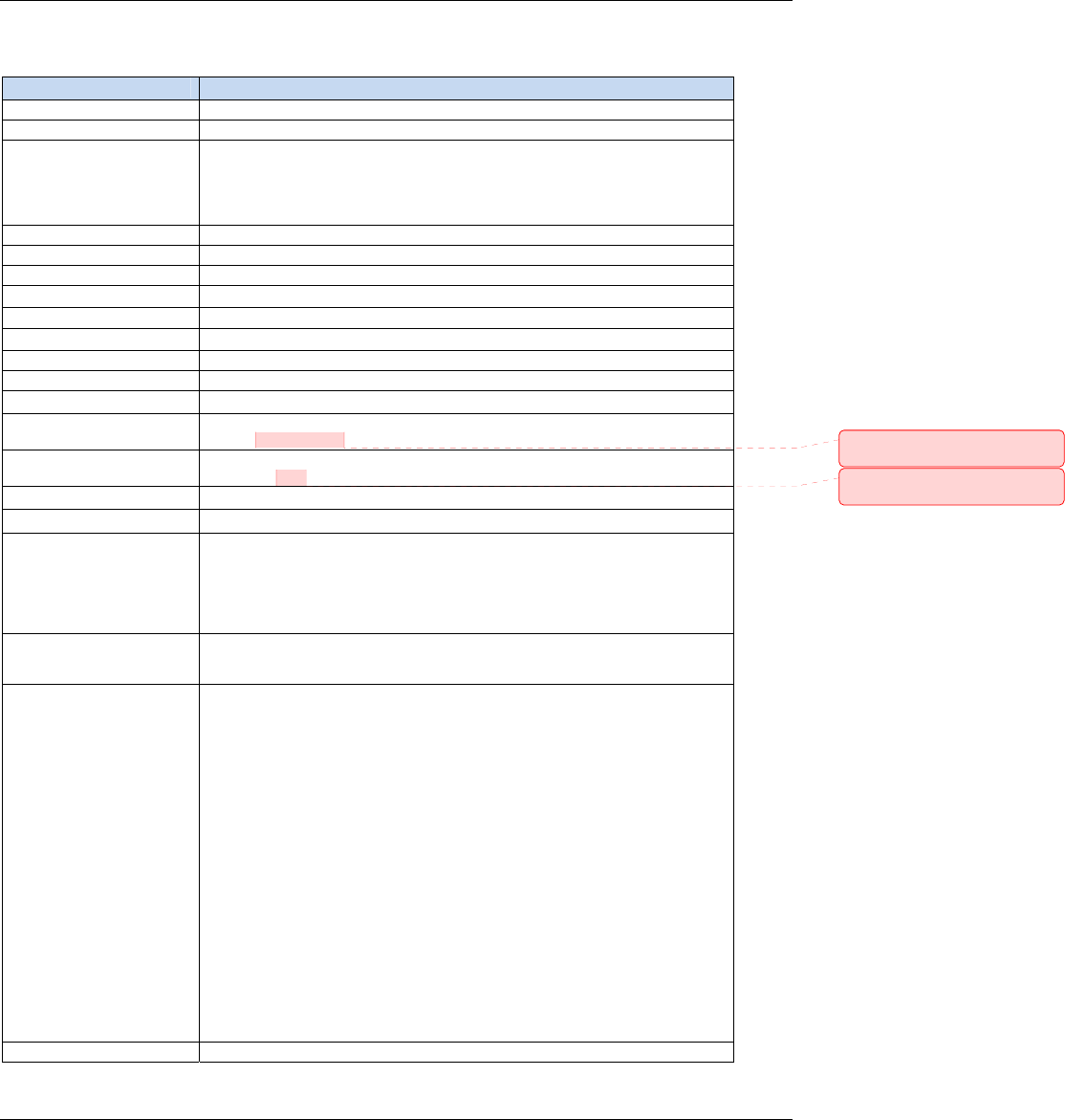
Technical Specifications
The MTSMC-G2 and MTSMC-G2-IP SocketModems meet the following specifications:
Category Description
Standards GPRS Class 10
Frequency Bands Quad-band GSM/EGPRS 850/900/1800/1900 MHz
Serial/Data Speed Serial interface supports DTE speeds up to 921.6K
IP interface supports DTE speeds at the fixed rate of 115.2
Packet data up to 85.6K bps
Circuit-switched data (GPRS) up to 14.4K bps transparent and non-transparent
Supports data rates of 921600, 460800, 230400, 115200 bps
Data Format 10 bit Serial Asynchronous
Data Error Correction MNP2
Data Compression V.42bis
Weight 1 oz. (28 g)
Size 3.15" x 1.375" (80.010 mm x 34.925 mm)
Operating Temperature -40° C to +85° C
Storage Temperature -40 °C to +85°C
Humidity 10% to 90%
Input Power 5VDC
Operating Voltage Supply Range: VCC
Maximum: 5.5
Voltage at Any Signal Pin Minimum: GND
Maximum: VCC
Antenna Connector Surface mount UFL
SIM Holder Standard 3V SIM holder
IP Protocols Supported MTSMC-G2
DNS Resolve, FTP client, LCP, PPP (dial-out),TCP socket, UDP socket, PAP &
CHAP authentication
MTSMC-G2-IP
DNS Resolve, FTP client, Ping, POP3 client, PPP (dial-out), SMTP, TCP RAW client
& server, UDP RAW client & server, PAP & CHAP authentication
M2M Applications MTSMC-G2-IP
Automatic connect/reconnect, device monitor, modem emulation, Ping & TCP keep
alive, wake-up on caller ID, wake-up on ring
Compliance EMC Compliance
FCC Part 15
EN55022
EN55024
Radio Compliance
FCC Part 22
FCC Part 24
RSS 132
RSS 133
EN 301 511
EN 301 489-1
EN 301 489-7
AS/ACIF S042.1
AS/ACIF S042.3
Safety Compliance
UL 60950-1
cUL 60950-1
EN 60950-1
AS/NZS 60950-1
Network Compliance
PTCRB
GCF
Warranty Two years
Comment [DAR1]: From Dustin
6/24/09
Comment [DAR2]: From Dustin
6/24/09
6
Specifications Continued:
Category Description
Features Modes of Operation: Data Mode, Command Mode, and Voice Mode
Embedded TCP/IP stack
Short Message Services (SMS)
RTS/CTS hardware flow control
AT command compatible
Support for HR, FR, EFR, and AMR (Adaptive Multi Rate) voice codec support
Flash upgradeable
Non-volatile memory
Electrical Characteristics
Units: Volts
5V DC Characteristics (VDD = 5V ± 0.25V) VDDMAX = 5.25V
Parameter Minimum Maximum
Digital Signal Input Low Level
–DTR (40), –TXD (35), –RTS (33)
GND 0.8
Digital Signal Input High Level
–DTR (40), –TXD (35), –RTS (33)
2 Vcc
Digital Signal Output Low Level
–DCD (39), –CTS (38), –DSR (37), –RI (36), –RXD (34)
0.4
Digital Signal Output High Level
–DCD (39), –CTS (38), –DSR (37), –RI (36), –RXD (34)
3.84
Reset (Low Active) Input Low Level
–Reset (24)
0.8
Reset (Low Active) Input High Level
–Reset (24)
2
Digital Input Capacitance 14pF
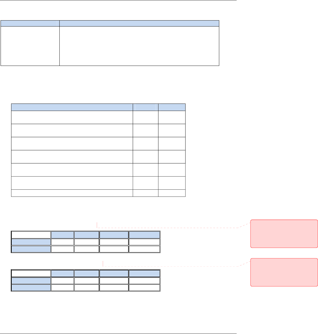
Power Consumption
MTSMC-G2 Measured Power* Measures at Input Voltage 5.00
Sleep Typical Maximum Peak
Current (AMPS) 0.049 0.113 0.24 1.10
Watts 0.245 0.564 1.195
MTSMC-G2-IP Measured Power* Measures at Input Voltage 5.00
Sleep Typical Maximum Peak
Current (AMPS) 0.080 0.135 0.280 1.250
Watts 0.382 0.664 1.358
Note: Current Peak = 1500mA maximum during Tx burst.
* Multi-Tech Systems, Inc. recommends that the customer incorporate a 10% buffer into their power source when
determining product load.
Comment [DAR3]: Measurements
for MTSMC-G2-IP 73120965 Rev 0
from Tom Fix. He suggested the
current peak text also 4/22/09. He
said these measurements apply to G2
without IP, too.
Comment [DAR4]: Measurements
for MTSMC-G2-IP 73120965 Rev 0
from Tom Fix. He suggested the
current peak text also 4/22/09. He
said these measurements apply to G2
without IP, too.
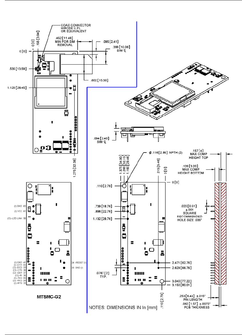
Mechanical Drawings – Basic Build
7
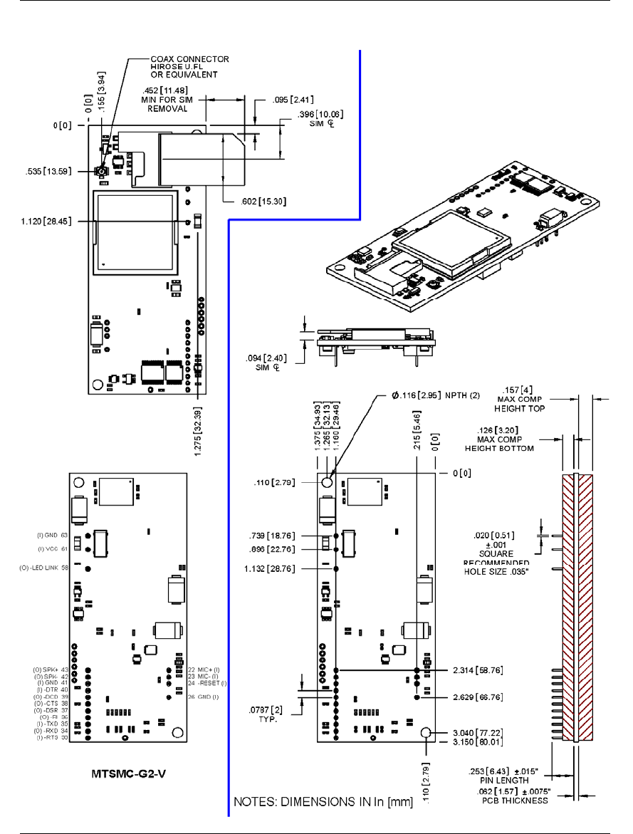
Mechanical Drawings – Voice Build
8
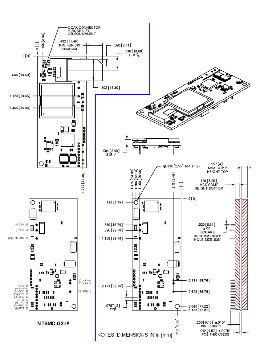
Mechanical Drawings – IP Build
9

Application Notes
Flashing LED Interface
The flashing LED signal is used to indicate the working mode of the SocketModem.
LEDs and SocketModem Status
Signal SocketModem Status
OFF Download mode or switched OFF>
Continuously lit Switched ON (not registered on the network) ON
Flashing Switched ON (registered on the network)
RF Performances
RF performances are compliant with the ETSI recommendation 05.05 and 11.10.
10
Note: The following statistics are subject to change due to pending test results. Comment [DAR5]: Tom Hofstedt
expects text results in by June 24th.
The main parameters are:
Receiver Features
• EGSM Sensitivity : < -104 dBm
• GSM 1800/GSM 1900 Sensitivity : < -102 dBm
• Selectivity @ 200 kHz : > +9 dBc
• Selectivity @ 400 kHz : > +41 dBc
• Dynamic range : 62 dB
• Intermodulation : > -43 dBm
• Co-channel rejection : + 9 dBc
Transmitter Features
• Maximum output power (EGSM) : 33 dBm ± 2 dB
• Maximum output power (DCS/PCS) : 30 dBm ± 2 dB
• Minimum output power (EGSM): 5 dBm ± 5 dB
• Minimum output power (DCS/PCS): 0 dBm ± 5 dB
• H2 level : < -30 dBm
• H3 level : < -30 dBm
• Noise in 925 - 935 MHz : < -67 dBm
• Noise in 935 - 960 MHz : < -79 dBm
• Noise in 1805 - 1880 MHz : < -71 dBm
• Phase error at peak power : < 5 ° RMS
• Frequency error : ± 0.1 ppm max
RF Connection and Antenna
The RF connector on the SocketModem GPRS is a UFL standard type. See Chapter 1 for Antenna System details.
Microphone Inputs
The MIC inputs are differential ones. They already include the convenient biasing for an electret microphone (0.5 mA
and 2 Volts). This electret microphone can be directly connected on these inputs. The impedance of the microphone
has to be around 2K. These inputs are the standard ones for a handset design.
The gain of the MIC inputs is internally adjusted. The gain can be tuned from 30dB to 51dB. The connection to the
microphone is direct.
MIC2N
MIC2P
C1
C1 = 22pF to 100 pF
33 pF recommended

11
Changing the Quad Band
The SocketModem Cell and the SocketModem iCell both support quad band frequencies (850/1900/900/1800 MHz).
In reality, these products operate like dual, dual-band devices. In other words, they can be configured for 850/1900 or
900/1800 MHz. They do not auto-seek the local area frequency.
Build Options
These wireless modems can be ordered with the default set to 850/1900 MHz or 900/1800 MHz.
• 850/1900 MHz – The wireless modem defaulting to 850/1900 MHz is the default build option.
• 900/1800 MHz – The wireless modem defaulting to 900/1800 MHz is identified with -ED in the product
ordering number which signifies European default.
Changing the GSM Band
If for any reason, such as moving the modem from one geographical area to another, you want to change the
band, you can accomplish this by using the +WMBS AT Command.
Steps for Changing the GSM Band
Use a terminal application such as HyperTerminal for entering the AT Command.
1. To open HyperTerminal, click Start. Then select Programs > Accessories > Communications. Then
click HyperTerminal.
2. When the command window opens, type AT+WMBS=<Band><Param>. Press Enter.
• For <Band>, enter the option you desire:
4 = Dual-band mode 850/1900MHz
5 = Dual-band mode 900/1800MHz
• For <Param>, enter the option you desire:
0 = Modem must be reset in order to use the specified band(s). This is the default.
1 = Modem restarts immediately using the specified band(s).
Example: AT+WMBS=4,0. Press Enter.
12
Chapter 2 – The Antenna System
Antenna System for Embedded GSM Modems
The antenna system for use with the GSM modem includes a coax cable to interface between the UFL connection
on the modem and the antenna.
RF Specifications
GSM/EGSM RF Specifications
GSM 850 EGSM 900 GSM 1800 GSM 1900
Frequency RX 869 to 894 MHz 925 to 960 MHz 1805 to 1880 MHz 1930 to 1990 MHz
Frequency TX 824 to 849 MHz 880 to 915 MHz 1710 to 1785 MHz 1850 to 1910 MHz
RF Power Stand 2W at 12.5% duty
cycle 2W at 12.5% duty
cycle 1W at 12.5% duty
cycle 1W at 12.5% duty
cycle
Coax Cable
An optional 6” antenna cable (SMA Jack to UFL Plug) can be ordered from Multi-Tech Systems, Inc.
Part Number Description
CASMA-UFL-1 SMA to UFL COAX RF 6 inch cable (Single Pack)
CASMA-UFL-10 SMA to UFL COAX RF 6 inch cable (Ten Pack)
Cable Specifications
Cable Type: Dia. 1.13mm Coaxial Cable
Attenuation: <1.0db
Connector Impedance: 50 ohm
Antenna
GSM Antenna Requirements/Specifications
Frequency Range: 824 – 960 MHz / 1710 – 1990 MHz
Impedance: 50 ohm
VSWR: <2.0:1
Typical Radiated Gain: 0 dBi on azimuth plane
Radiation: Omni
Polarization: Vertical
Wave: Half Wave Dipole
Antennas Available from Multi-Tech:
Quad Band Description Qty Part Number
Hinged Right Angle 800/900/1800/1900 MHz Cellular Modem Antenna 1 ANQB-1HRA
Hinged Right Angle 800/900/1800/1900 MHz Cellular Modem Antenna 10 ANQB-10HRA
Hinged Right Angle 800/900/1800/1900 MHz Cellular Modem Antenna 50 ANQB-50HRA
PTCRB Requirements Note:
There cannot be any alteration to the authorized antenna system. The antenna system must be the same type
with similar in-band and out-of-band radiation patterns and maintain the same specifications.
FCC Requirements Note:
The antenna gain, including cable loss, must not exceed 3.0 dBi at 1900 MHz / 1.6 dBi at 850 MHz for mobile
operating configurations and 7.0 dBi at 1900 MHz / 2.3 dBi at 850 MHz for fixed mounted operations, as defined
in 2.1091 and 1.1307 of the rules for satisfying RF exposure compliance.

13
Chapter 3 – Design Considerations
Noise Suppression Design Considerations
Engineering noise-suppression practices must be adhered to when designing a printed circuit board (PCB)
containing the SocketModem module. Suppression of noise is essential to the proper operation and performance
of the modem itself and for surrounding equipment.
Two aspects of noise in an OEM board design containing the SocketModem must be considered: onboard/off-
board generated noise that can affect digital signal processing. Both on-board and off-board generated noise that
is coupled on-board can affect interface signal levels and quality. Of particular concern is noise in frequency
ranges affecting modem performance.
On-board generated electromagnetic interference (EMI) noise that can be radiated or conducted offboard is a
separate, but equally important, concern. This type of noise can affect the operation of surrounding equipment.
Most local government agencies have stringent certification requirements that must be met for use in specific
environments.
Proper PC board layout (component placement, signal routing, trace thickness and geometry, etc.) component
selection (composition, value, and tolerance), interface connections, and shielding are required for the board
design to achieve desired modem performance and to attain EMI certification.
Other aspects of proper noise-suppression engineering practices are beyond the scope of this designer guide.
The designer should consult noise suppression techniques described in technical publications and journals,
electronics and electrical engineering text books, and component supplier application notes.
PC Board Layout Guidelines
In a 4-layer design, provide adequate ground plane covering the entire board. In 4-layer designs, power and
ground are typically on the inner layers. All power and ground traces should be 0.05 inches wide.
The recommended hole size for the SocketModem pins is 0.036 in. +/-0.003 in. in diameter. Spacers can be used
to hold the SocketModem vertically in place during the wave solder process. A spacer should be placed on pin 32
and pin 64 of the SocketModem. A suggested part number for the spacer is BIVAR 938-0.130 for P1 (0.310in)
option SocketModems. The spacers can be left on permanently and will not effect operation.
All creepages and clearances for the SocketModem have been designed to meet requirements of safety
standards EN60950 or EN60601. The requirements are based on a working voltage of 125V or 250V. When the
recommended DAA* circuit interface is implemented in a third party design, all creepage and clearance
requirements must be strictly followed in order to meet safety standards. The third party safety design must be
evaluated by the appropriate national agency per the required specification.
User accessible areas: Based on where the third party design is to be marketed, sold, or used, it may be
necessary to provide an insulating cover over all TNV exposed areas. Consult with the recognized safety agency
to determine the requirements.
Note: Even if the recommended design considerations are followed, there are no guarantees that a particular
system will comply with all the necessary regulatory requirements. It is imperative that specific designs be
completely evaluated by a qualified/recognized agency.
*DAA stands for Data Access Arrangement. DAA is the telephone line interface of the module.
Electromagnetic Interference (EMI) Considerations
The following guidelines are offered specifically to help minimize EMI generation. Some of these guidelines are
the same as, or similar to, the general guidelines but are mentioned again to reinforce their importance. In order
to minimize the contribution of the SocketModem-based design to EMI, the designer must understand the major
sources of EMI and how to reduce them to acceptable levels.
1. Keep traces carrying high frequency signals as short as possible.
2. Provide a good ground plane or grid. In some cases, a multilayer board may be required with full layers for
ground and power distribution.

14
3. Decouple power from ground with decoupling capacitors as close to the SocketModem module power pins as
possible.
4. Eliminate ground loops, which are unexpected current return paths to the power source and ground.
5. Decouple the telephone line cables at the telephone line jacks. Typically, use a combination of series inductors,
common mode chokes, and shunt capacitors. Methods to decouple telephone lines are similar to decoupling
power lines; however, telephone line decoupling may be more difficult and deserves additional attention. A
commonly used design aid is to place footprints for these components and populate as necessary during
performance/EMI testing and certification.
6. Decouple the power cord at the power cord interface with decoupling capacitors. Methods to decouple power
lines are similar to decoupling telephone lines.
7. Locate high frequency circuits in a separate area to minimize capacitive coupling to other circuits.
8. Locate cables and connectors so as to avoid coupling from high frequency circuits.
9. Lay out the highest frequency signal traces next to the ground grid.
10. If a multilayer board design is used, make no cuts in the ground or power planes and be sure the ground
plane covers all traces.
11. Minimize the number of through-hole connections on traces carrying high frequency signals.
12. Avoid right angle turns on high frequency traces. Forty-five degree corners are good; however, radius turns
are better.
13. On 2-layer boards with no ground grid, provide a shadow ground trace on the opposite side of the board to
traces carrying high frequency signals. This will be effective as a high frequency ground return if it is three times
the width of the signal traces.
14. Distribute high frequency signals continuously on a single trace rather than several traces radiating from one
point.
Electrostatic Discharge Control
All electronic devices should be handled with certain precautions to avoid damage due to the accumulation of
static charge.
See the ANSI/ESD Association Standard (ANSI/ESD S20.20-1999) – a document “for the Development of an
Electrostatic Discharge Control for Protection of Electrical and Electronic Parts, Assemblies and Equipment.” This
document covers ESD Control Program Administrative Requirements, ESD Training, ESD Control Program Plan
Technical Requirements (grounding/bonding systems, personnel grooming, protected areas, packaging, marking,
equipment, and handling), and Sensitivity Testing.
Multi-Tech Systems, Inc. strives to follow all of these recommendations. Input protection circuitry has been
incorporated into the Multi-Tech devices to minimize the effect of this static buildup, proper precautions should be
taken to avoid exposure to electrostatic discharge during handling.
Multi-Tech uses and recommends that others use anti-static boxes that create a faraday cage (packaging
designed to exclude electromagnetic fields). Multi-Tech recommends that you use our packaging when returning
a product and when you ship your products to your customers.

15
Chapter 4 – Safety Notices and
Warnings
Note to OEMs: The following safety statements may be used in the documentation of your final product
applications.
Telecom Safety Warning
1. Never install telephone wiring during a lightning storm.
2. Never install a telephone jack in wet locations unless the jack is specifically designed for wet locations.
3. This product is to be used with UL and cUL listed computers.
4. Never touch uninsulated telephone wires or terminals unless the telephone line has been disconnected at
the network interface.
5. Use caution when installing or modifying telephone lines.
6. Avoid using a telephone during an electrical storm. There may be a remote risk of electrical shock from
lightning.
7. Do not use a telephone in the vicinity of a gas leak.
8. To reduce the risk of fire, use only 26 AWG or larger telecommunication line cord.
9. This product must be disconnected from its power source and telephone network interface when servicing.
Wireless Safety
General Safety
The modem is designed for and intended to be used in fixed and mobile applications. “Fixed” means that the
device is physically secured at one location and is not able to be easily moved to another location. “Mobile”
means that the device is designed to be used in other than fixed locations.
RF Safety
The remote modems are wireless cellular telephones devices. It is important to follow any special
regulations regarding the use of radio equipment due in particular to the possibility of Radio Frequency (RF)
interference.
Caution: A separation distance of at least 20 cm must be maintained between the modem transmitter’s
antenna and the body of the user or nearby persons. The modem is not designed for or intended to be used
in portable applications within 20 cm of the body of the user. In particular, if using a Yagi antenna, it must be
in a location that prevents public exposure to the radiation limits being exceeded. Check your local
standards regarding safe distances, etc.
• Wireless modems in an ATM in, for example, a hospital environment and any other place where medical
equipment may be in use, may be a hazard. This statement also applies to inadequately protected
personal medical devices such as hearing aids and pacemakers.
• Operation of a wireless modem close to other electronic equipment may also cause interference if the
equipment is inadequately protected. Observe any warning signs and manufacturers’ recommendations.
• The modems must not be operated around gasoline or diesel-fuel.
RF Interference Safety
It is important to follow any special regulations regarding the use of radio equipment due in particular to the
possibility of radio frequency, RF, interference. Please follow the safety advice given below carefully.
• Switch OFF your Wireless MultiModem when in an aircraft. The use of cellular telephones in an aircraft
may endanger the operation of the aircraft, disrupt the cellular network and is illegal. Failure to observe
this instruction may lead to suspension or denial of cellular telephone services to the offender, or legal
action or both.
• Switch OFF your Wireless MultiModem when around gasoline or diesel-fuel pumps and before filling your
vehicle with fuel.

16
• Switch OFF your wireless device in hospitals and any other place where medical equipment may be in
use.
• Respect restrictions on the use of radio equipment in fuel depots, chemical plants or where blasting
operations are in progress.
• There may be a hazard associated with the operation of your wireless device close to inadequately
protected personal medical devices such as hearing aids and pacemakers. Consult the manufacturers of
the medical device to determine if it is adequately protected.
• Operation of your wireless device close to other electronic equipment may also cause interference if the
equipment is inadequately protected. Observe any warning signs and manufacturers’ recommendations.
Vehicle Safety
• Do not use your wireless device while driving.
• Respect national regulations on the use of cellular telephones in vehicles. Road safety always comes first.
• If incorrectly installed in a vehicle, the operation of a wireless telephone could interfere with the correct
functioning of vehicle electronics. To avoid such problems, be sure that qualified personnel have
performed the installation. Verification of the protection of vehicle electronics should be part of the
installation.
• The use of an alert device to operate a vehicle’s lights or horn on public roads is not permitted.
Maintenance of Your Wireless Device
Your wireless device is the product of advanced engineering, design, and craftsmanship and should be
treated with care. The suggestions below will help you to enjoy this product for many years.
• Do not expose the wireless device to any extreme environment where the temperature is above 50ºC or
humidity is above 90% noncondensing.
• Do not attempt to disassemble the wireless device. There are no user serviceable parts inside.
• Do not expose the wireless device to water, rain, or spilled beverages. It is not waterproof.
• Do not place the wireless device alongside computer discs, credit or travel cards, or other magnetic
media. The phone may affect the information contained on discs or cards.
• The use of accessories not authorized by Multi-Tech or not compliant with Multi-Tech's accessory
specifications may invalidate the warranty of the wireless device.
• In the unlikely event of a fault in the wireless device, contact Multi-Tech Tech Support.
Your Responsibility
This wireless device is your responsibility. Please treat it with care respecting all local regulations. It is not a
toy. Therefore, keep it in a safe place at all times and out of the reach of children.
Try to remember your Unlock and PIN codes. Become familiar with and use the security features to block
unauthorized use and theft.
Upgrading Firmware
Your modem is controlled by semi-permanent firmware, which is stored in flash memory. Multi-Tech's firmware is nonvolatile;
that is, it remains stored in memory when the modem is turned off and can be upgraded as new features are added.
Multi-Tech's Flash Wizard can be downloaded from Multi-Tech’s FTP site and is available on CD. Use this Flash Wizard for
upgrading your firmware. Documentation for using the Flash Wizard is included with the wizard.
The following table shows you which products support the Flash Wizard.
Wireless SocketModems
SocketModem GPRS MTSMC-G2 Do not use the Flash Wizard for the wireless modems. Contact
Multi-Tech for wireless modem firmware upgrade directions.
Account Activation for Wireless Devices
Pre-Configured Multi-Tech Products
Some Multi-Tech wireless modems have been pre-configured to operate on a specific wireless network, such as Sprint and
Verizon.
However, before you can begin to use the modem, you must set up a wireless data account with your wireless
network provider. Then, follow the activation procedures covered on the Activation Notices available from Multi-Tech.
Wireless Approvals and Labeling Requirements
Wireless Approvals (GSM, CDMA)
The Multi-Tech SocketModem is Industry and/or Carrier Approved as an End Product modem. In most cases, when
integrated and used with an antenna system that was part of the Multi-Tech modem certification, no additional
approvals or certification is required (however, CDMA has a few exceptions) for the device you develop as long as
the following are met:
• PTCRB Requirements:
The antenna system cannot be altered.
• Model Identification:
IMPORTANT
When the wireless carrier asks you to provide the modem's model identification,
give the Multi-Tech wireless model identification, not the identification of the host device model.
See the label example below.
The Multi-Tech model identification allows the carrier to verify the modem as one of its approved models.
This information is located on the modem's label.
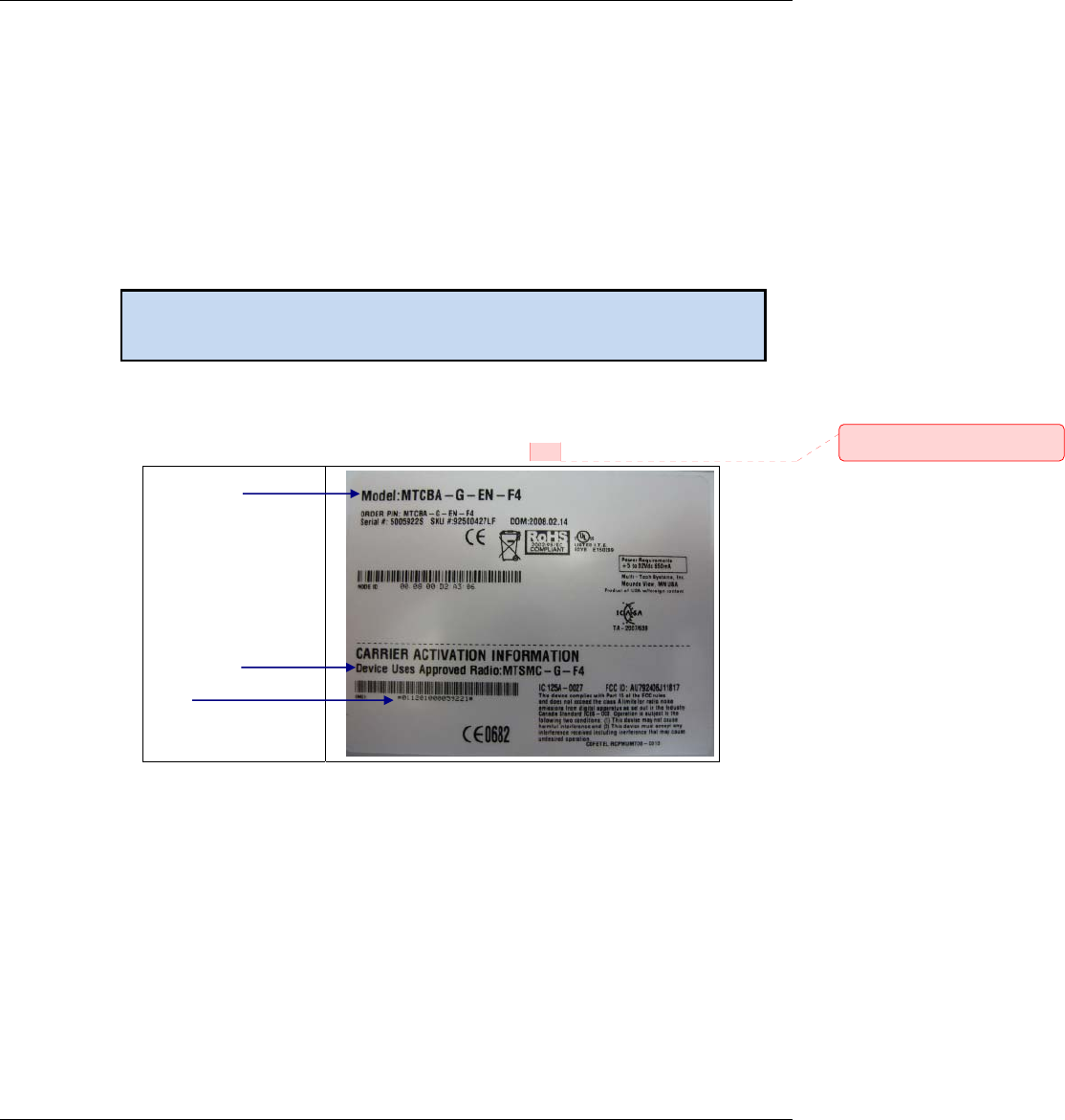
The Following Is an Example of an End Product GPRS Label:
17
Host Device Model
Identification
Multi-Tech
SocketModem Model
Identification
IMEI
(International Mobile
Equipment Identity)
Comment [DAR6]: Label_GPRS_F
4.png
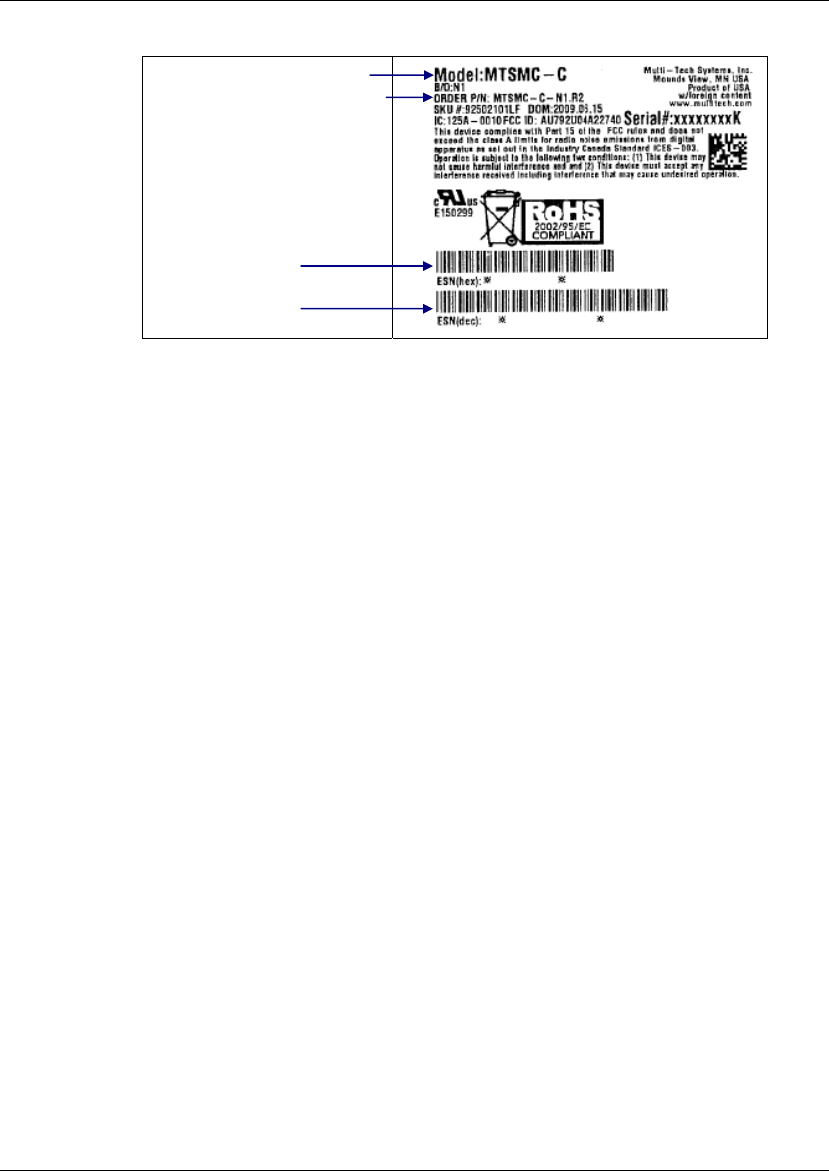
The Following Is an Example of a CDMA Label:
Multi-Tech Model Identification
Multi-Tech Ordering Part Number
ESN:
Electronic Serial Number in
Hexadecimal Format
and Decimal Format
• Other Information the Wireless Carrier Asks You to Provide:
For CDMA SocketModems: The modem's 8-character ESN (Electronic Serial Number) number printed next
to the barcode on the modem. The ESN may vary in format by various CDMA carriers; some use a decimal
number while others use a hexadecimal number.
For GSM SocketModems: The modem's 15-character IMEI (International Mobile Equipment Identity)
number printed on the modem's label.
18

Regulatory Compliance Statements
EMC, Safety, and R&TTE Directive Compliance
The CE mark is affixed to this product to confirm compliance with the following European Community Directives:
Council Directive 2004/108/EC of 15 December 2004 on the approximation of the laws of Member States
relating to electromagnetic compatibility;
and
Council Directive 2006/95/EC of 12 December 2006 on the harmonization of the laws of Member States
relating to electrical equipment designed for use within certain voltage limits;
and
Council Directive 1999/5/EC of 9 March 1999 on radio equipment and telecommunications terminal
equipment and the mutual recognition of their conformity.
International Modem Restrictions
Some dialing and answering defaults and restrictions may vary for international modems. Changing settings may
cause a modem to become non-compliant with national telecom requirements in specific countries. Also note
that some software packages may have features or lack restrictions that may cause the modem to become non-
compliant.
EMC Requirements for the United States
47 CFR – FCC Part 15 Regulation
This equipment has been tested and found to comply with the limits for a Class B digital device, pursuant to
47 CFR – FCC Part 15 regulations. The stated limits in this regulation are designed to provide reasonable
protection against harmful interference in a residential environment. This equipment generates, uses, and can
radiate radio frequency energy, and if not installed and used in accordance with the instructions, may cause
harmful interference to radio communications. However, there is no guarantee that interference will not occur in a
particular installation. If this equipment does cause harmful interference to radio or television reception, which
can be determined by turning the equipment off and on, the user is encouraged to try to correct the interference
by one or more of the following measures:
• Reorient or relocate the receiving antenna.
• Increase the separation between the equipment and receiver.
• Plug the equipment into an outlet on a circuit different from that to which the receiver is connected.
• Consult the dealer or an experienced radio/TV technician for help.
This device complies with 47 CFR – FCC Part 15 rules. Operation of this device is subject to the following
conditions:
(1) This device may not cause harmful interference, and
(2) This device must accept any interference that may cause undesired operation.
Warning: Changes or modifications to this unit not expressly approved by the party responsible for compliance
could void the user’s authority to operate the equipment.
EMC Requirements for Industry Canada
This Class B digital apparatus meets all requirements of the Canadian Interference-Causing Equipment
Regulations.
Cet appareil numérique de la classe B respecte toutes les exigences du Reglement Canadien sur le matériel
brouilleur.
19

20
New Zealand Telecom Warning Notice
1. The grant of a Telepermit for any item of terminal equipment indicates only that Telecom has accepted that
the item complies with minimum conditions for connection to its network. It indicates no endorsement of the
product by Telecom, nor does it provide any sort of warranty. Above all, it provides no assurance that any
item will work correctly in all respects with another item of Telepermitted equipment of a different make or
model, nor does it imply that any product is compatible with all of Telecom’s network services.
This equipment is not capable under all operating conditions of correct operating conditions of correct
operation at the higher speed which it is designated. 33.6 kbps and 56 kbps connections are likely to be
restricted to lower bit rates when connected to some PSTN implementations. Telecom will accept no
responsibility should difficulties arise in such circumstances.
2. Immediately disconnect this equipment should it become physically damaged, and arrange for its disposal or
repair.
3. This modem shall not be used in any manner which could constitute a nuisance to other Telecom
customers.
4. This device is equipped with pulse dialing, while the Telecom standard is DTMF tone dialing. There is no
guarantee that Telecom lines will always continue to support pulse dialing.
Use of pulse dialing, when this equipment is connected to the same line as other equipment, may give rise
to 'bell tinkle' or noise and may also cause a false answer condition. Should such problems occur, the user
should NOT contact the Telecom Faults Service.
The preferred method of dialing is to use DTMF tones, as this is faster than pulse (decadic) dialing and is
readily available on almost all New Zealand telephone exchanges.
5. Warning Notice: No '111' or other calls can be made from this device during a mains power failure.
6. This equipment may not provide for the effective hand-over of a call to another device connected to the
same line.
7. Some parameters required for compliance with Telecom’s Telepermit requirements are dependent on the
equipment (PC) associated with this device. The associated equipment shall be set to operate within the
following limits for compliance with Telecom’s Specifications:
For repeat calls to the same number:
• There shall be no more than 10 call attempts to the same number within any 30 minute period for
any single manual call initiation, and
• The equipment shall go on-hook for a period of not less than 30 seconds between the end of one
attempt and the beginning of the next attempt.
For automatic calls to different numbers:
• The equipment shall be set to ensure that automatic calls to different numbers are spaced such
that there is no less than 5 seconds between the end of one call attempt and the beginning of
another.
8. For correct operation, total of the RN’s of all devices connected to a single line at any time should not
exceed 5.
South African Statement
This modem must be used in conjunction with an approved surge protection device.
Thailand Approval for MT9234SMI
This telecom device conforms to NTC* requirements.
*NTC is the National Telecommunications Commission, Thailand’s telecommunications regulator.
“เครื่องโทรคมนาคมและอุปกรณนี้ มีความสอดคลองตามขอกําหนดของ กทช.”
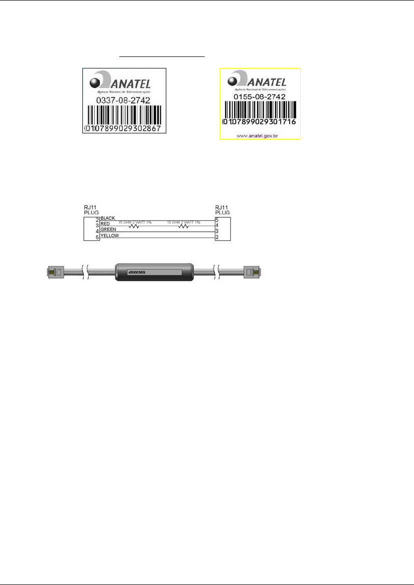
Brazil Approval for the MT9234SMI and MT5656SMI
This product has been homologated by ANATEL. This product meets the applied technical requirements in
accordance with the procedures regulated by ANATEL. Reference of homologation of this product can be viewed
in ANATEL web page: http://www.anatel.gov.br
Brazil Bar Code for MT9234SMI
Brazil Bar Code for MT5656SMI
Brazil Certification (MT9234SMI Model Only)
A special phone cable is required for regulatory compliance.
Um cabo especial para telefone é requerido para a conformidade regulatória.
Other
The above country-specific examples do not cover all countries with specific regulations; they are included to
show you how each country may differ. If you have trouble determining your own country's requirements, check
with Multi-Tech's Technical Support for assistance.
21
Waste Electrical and Electronic Equipment Statement
Note to OEMs: The statement is included for your information and may be used in the
documentation of your final product applications.
WEEE Directive
The WEEE directive places an obligation on EU-based manufacturers, distributors, retailers, and importers to take-
back electronics products at the end of their useful life. A sister Directive, ROHS (Restriction of Hazardous
Substances) complements the WEEE Directive by banning the presence of specific hazardous substances in the
products at the design phase. The WEEE Directive covers all Multi-Tech products imported into the EU as of August
13, 2005. EU-based manufacturers, distributors, retailers and importers are obliged to finance the costs of recovery
from municipal collection points, reuse, and recycling of specified percentages per the WEEE requirements.
Instructions for Disposal of WEEE by Users in the European Union
The symbol shown below is on the product or on its packaging, which indicates that this product must not be
disposed of with other waste. Instead, it is the user’s responsibility to dispose of their waste equipment by handing it
over to a designated collection point for the recycling of waste electrical and electronic equipment. The separate
collection and recycling of your waste equipment at the time of disposal will help to conserve natural resources and
ensure that it is recycled in a manner that protects human health and the environment. For more information about
where you can drop off your waste equipment for recycling, please contact your local city office, your household
waste disposal service or where you purchased the product.
July, 2005
22

Restriction of the Use of Hazardous Substances (RoHS)
Multi-Tech Systems, Inc.
Certificate of Compliance
2002/95/EC
Multi-Tech Systems Inc. confirms that its embedded products now comply with the chemical concentration limitations
set forth in the directive 2002/95/EC of the European Parliament (Restriction Of the use of certain Hazardous
Substances in electrical and electronic equipment - RoHS)
These Multi-Tech Systems, Inc. products do not contain the following banned chemicals:
Lead, [Pb] < 1000 PPM
Mercury, [Hg] < 1000 PPM
Hexavalent Chromium, [Cr+6] < 1000 PPM
Cadmium, [Cd] < 100 PPM
Polybrominated Biphenyl, [PBB] < 1000 PPM
Polybrominated Diphenyl Ether, [PBDE] < 1000 PPM
Moisture Sensitivity Level (MSL) =1
Tin Whisker Growth = None detected
Maximum Soldering temperature = 260C (wave only)
Notes:
1. Lead usage in some components is exempted by the following RoHS annex; therefore, higher lead
concentration would be found in some SocketModems (>1000ppm).
a. Lead in high melting temperature type solders (i.e., tin-lead solder alloys containing more than 85%
lead).
b. Lead in electronic ceramic parts (e.g., piezoelectronic devices).
2. Moisture Sensitivity Level (MSL) – Analysis is based on the components/material used on the board.
3. Tin Whisker Study was done per NEMI guidelines (Elevated temperature cycle of 60°C and non-condensing
relative humidity of 87% exposed to this environment for 1000 hours).
23
24
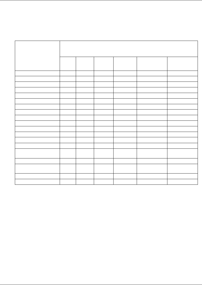
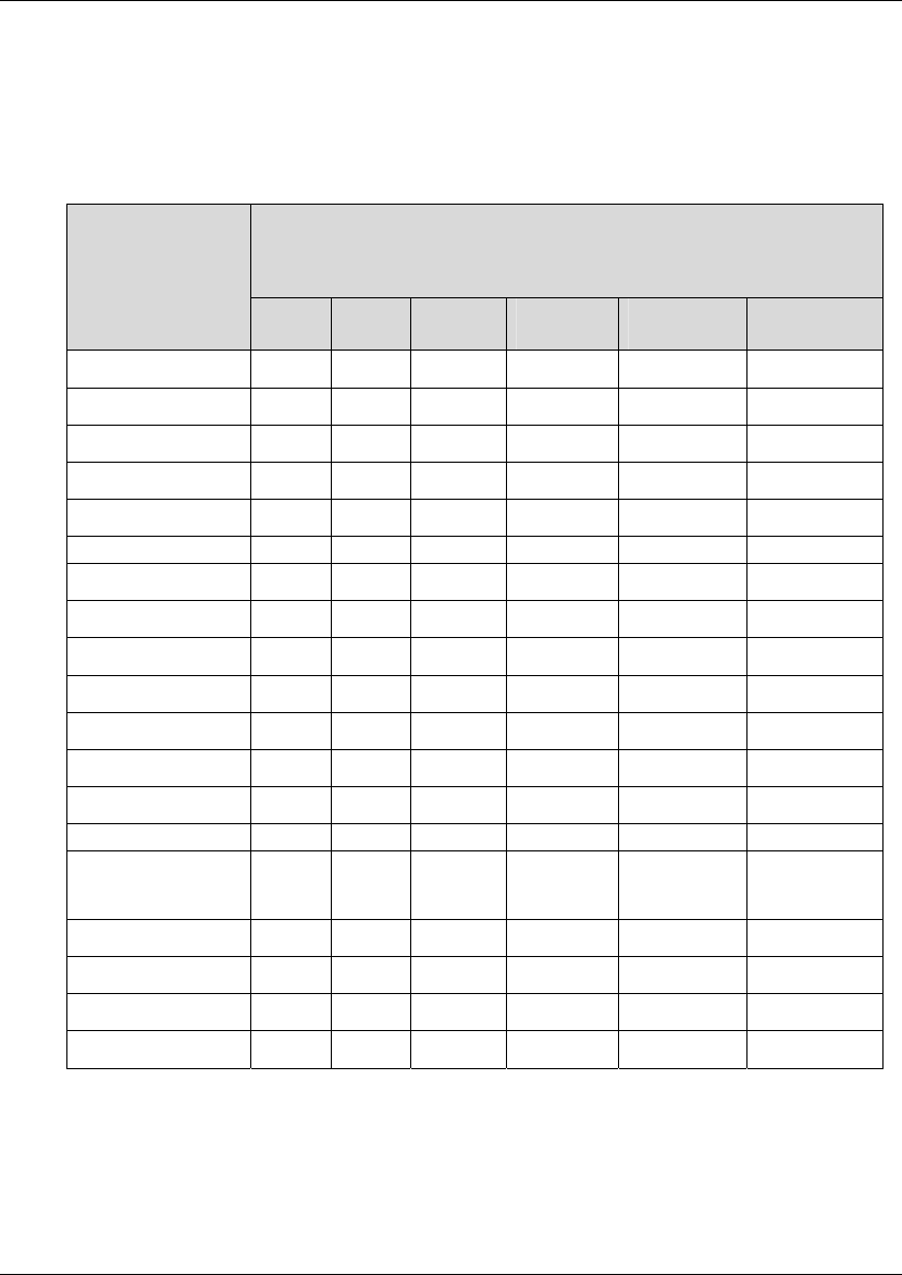
Information on HS/TS Substances according to Chinese Standards in English
In accordance with China’s Administrative Measures on the Control of Pollution Caused by Electronic
Information Products (EIP) # 39, also known as China RoHS, the following information is provided regarding
the names and concentration levels of Toxic Substances (TS) or Hazardous Substances (HS) which may be
contained in Multi-Tech Systems Inc. products relative to the EIP standards set by China’s Ministry of
Information Industry (MII).
Hazardous/Toxic Substance/Elements
Name of the
Component Lead
(PB)
Mercury
(Hg) Cadmium
(CD) Hexavalent
Chromium
(CR6+)
Polybrominated
Biphenyl (PBB) Polybrominated
Diphenyl Ether
(PBDE)
Printed Circuit Boards O O O O O O
Resistors X O O O O O
Capacitors X O O O O O
Ferrite Beads O O O O O O
Relays/Opticals O O O O O O
ICs O O O O O O
Diodes/ Transistors O O O O O O
Oscillators and Crystals X O O O O O
Regulator O O O O O O
Voltage Sensor O O O O O O
Transformer O O O O O O
Speaker O O O O O O
Connectors O O O O O O
LEDs O O O O O O
Screws, Nuts, and other
Hardware X O O O O O
ac-dc Power Supplies O O O O O O
Software /
Documentation CDs O O O O O O
Booklets and Paperwork O O O O O O
Chassis O O O O O O
X Represents that the concentration of such hazardous/toxic substance in all the
units of homogeneous material of such component is higher than the SJ/Txxx-2006
Requirements for Concentration Limits.
O Represents that no such substances are used or that the concentration is within
the aforementioned limits.
25
Information on HS/TS Substances According to Chinese Standards in Chinese
依照中国标准的有毒有害物质信息
根据中华人民共和国信息产业部 (MII) 制定的电子信息产品 (EIP)
标准-中华人民共和国《电子信息产品污染控制管理办法》(第 39 号),也称作中国 RoHS,下表列出了
Multi-Tech Systems, Inc. 产品中可能含有的有毒物质 (TS) 或有害物质 (HS) 的名称及含量水平方面的信息。
有害/有毒物质/元素
成分名称 铅
(PB)
汞
(Hg)
镉
(CD)
六价铬
(CR6+)
多溴联苯
(PBB)
多溴二苯醚
(PBDE)
印刷电路板 O O O O O O
电阻器 X O O O O O
电容器 X O O O O O
铁氧体磁环 O O O O O O
继电器/光学部件 O O O O O O
IC O O O O O O
二极管/晶体管 O O O O O O
振荡器和晶振 X O O O O O
调节器 O O O O O O
电压传感器 O O O O O O
变压器 O O O O O O
扬声器 O O O O O O
连接器 O O O O O O
LED O O O O O O
螺丝、螺母以及其它
五金件
X O O O O O
交流-直流电源 O O O O O O
软件/文档 CD O O O O O O
手册和纸页 O O O O O O
底盘 O O O O O O
X 表示所有使用类似材料的设备中有害/有毒物质的含量水平高于 SJ/Txxx-2006 限量要求。
O 表示不含该物质或者该物质的含量水平在上述限量要求之内。
26
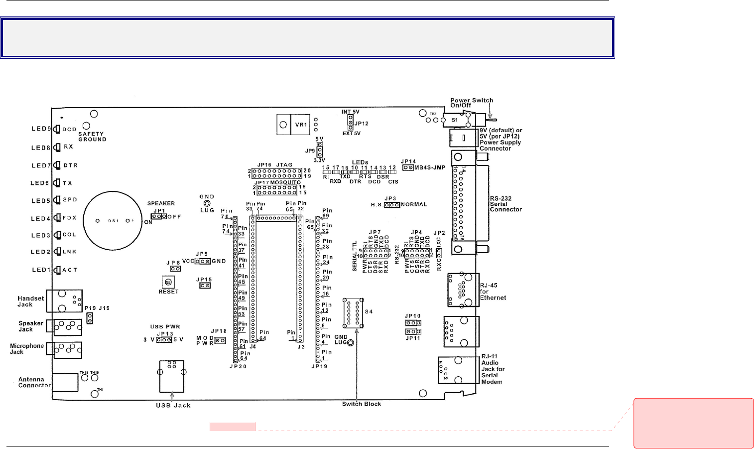
Chapter 5 – SocketModem Developer Board
SocketModem Developer Board
This developer board drawing shows the major board components for all SocketModems.
Board Revision B
See the next page for description of Board Components
Comment [DAR7]: C:\Universal_So
cketModem \ Graphics_ETC_Rev_I \
Board_B_Schematics \
SchematicsfromJohnM \
Board_B_for_Universal_260b0_forRe
v J jumper fixed.png
27
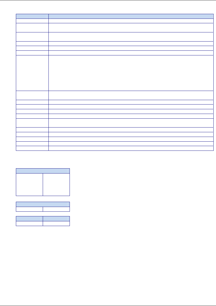
Board Components
Jumper Description
JP1 Mutes the speaker. Default positions are 1 and 2 (speaker is not muted).
JP2 Ties the TX and RX clock lines together. Default positions are 1 and 2 (transmit and receive
clock act independently).
JP3 Sets the data rate. NORMAL sets the data rate at 250kbps.
H.S. (high speed serial communications) sets the data rate at 1Mbps.
JP4 Testing interface (debugging) for the RS-232 signals.
JP5 JP5 acts as a replacement for pin 45 when pin 45 is used for another function.
JP7 Testing interface (debugging) for the serial TTL signals.
JP9 JP9 is the 5V / 3.3V regulator. The factory default operating voltage is 3.3V.
Warning – Be sure that the 5V / 3.3V jumper is set to match the requirements of your
SocketModem. If this jumper is set incorrectly, damage to the SocketModem and/or the
Test/Demo card could result.
Caution – Use only the provided Multi-Tech Systems, Inc. transformer with the Test/Demo
board. Use of any other power source will void the warranty and will likely damage the
Test/Demo board and the SocketModem. The transformer connector is keyed to prevent
improper connection to the Test/Demo board.
JP12 JP12 allows you to select either the internal 5V regulator (INT 5V) or to choose EXT 5V. For
the EXT 5V, you can use your own external 5V power source and plug it into J7.
JP13 Set either 5V or 3.3V for USB_VBUS line (supplied by the VCC of the USB jack).
JP14 Internal testing.
JP15 JP15 disconnects pin 45 from SLP with JP5 (the RS-232 driver sleep mode).
JP16 JTAG header.
JP17 Mosquito header. If used to debug the SocketModem while using the USB port, then the JP14
would have to be removed to disconnect USB_VBUS.
JP18 Power feed for area where SocketModems are placed (J24).
JP19 & JP20 Debugging probes.
JP25 & JP26 Ground lug.
S4 Set the switch block to the product being used.
S5 Reset
Jumpers and Corresponding Signals
J4 and J7
10 PWR
8 CTS
6 DSR
4 DTR
2 RXD
9 RI
7 RTS
5 GND
3 TXD
1 DCD
J2 and J13
2 RXC 1 TXC
JP10 JP11
TX Term RX Term
28
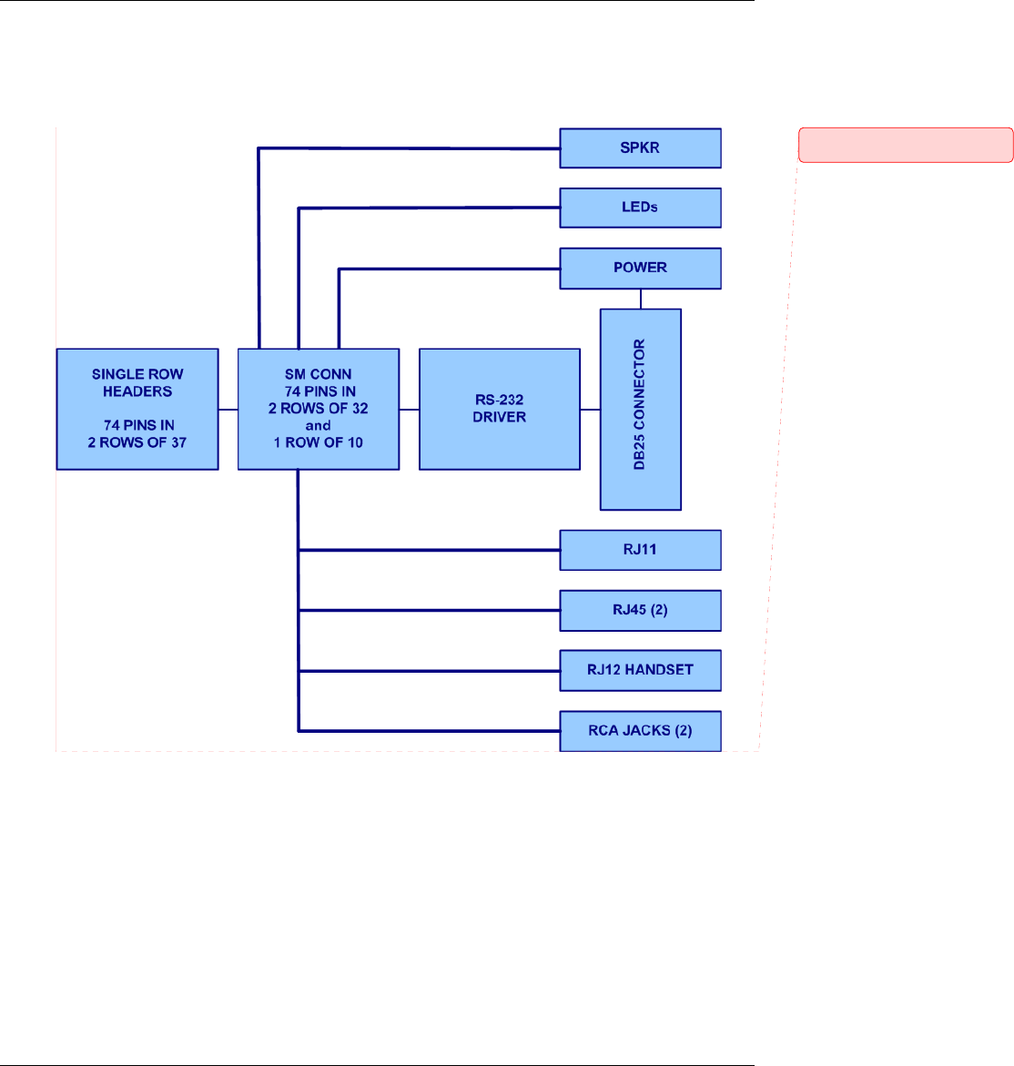
SocketModem Developer Board Block Diagram
Comment [DAR8]: Block Diagram
2008.png
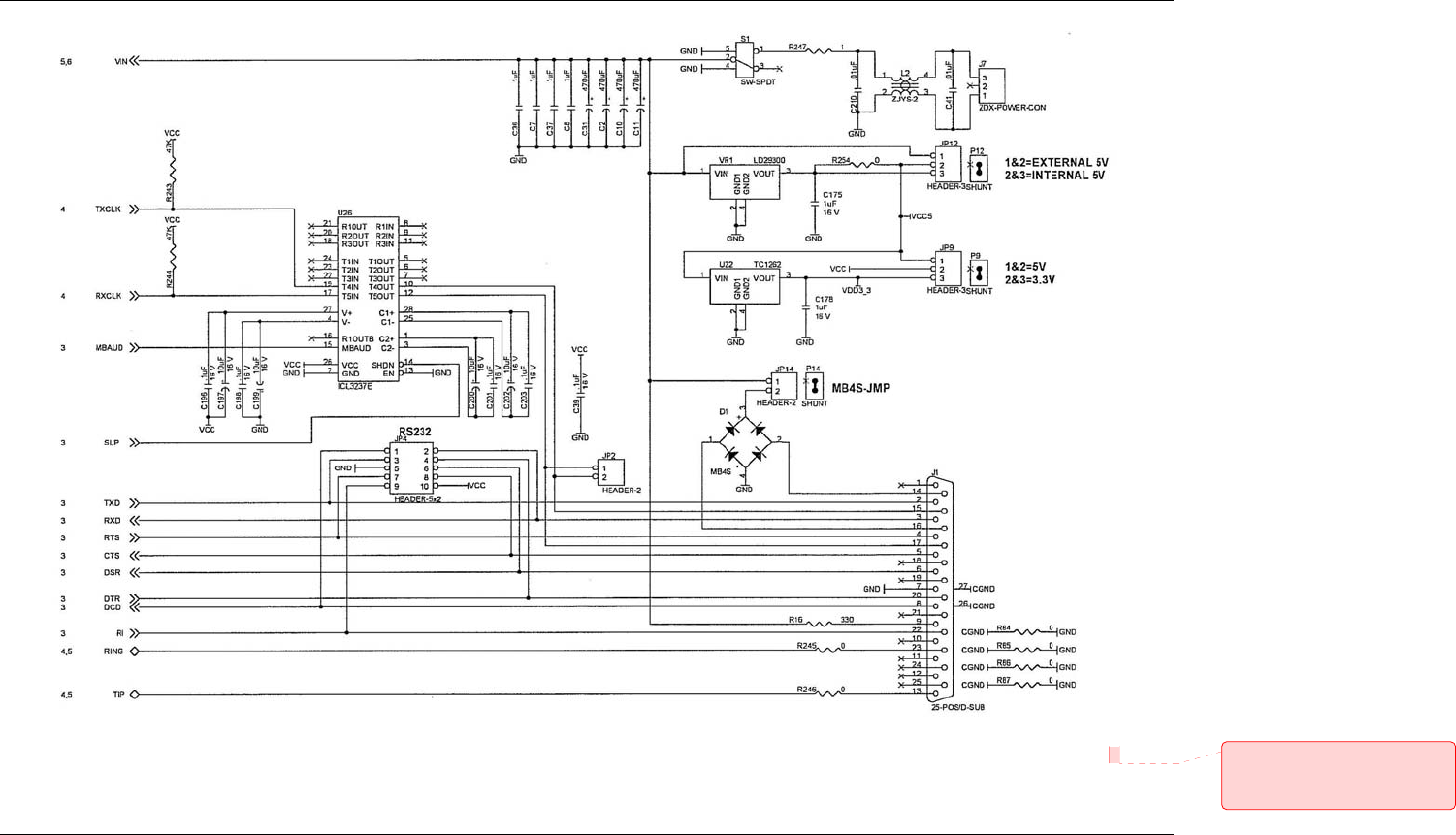
Developer Board Schematics
29
Board Revision B Comment [DAR9]: Schematics
Board B page 2 Scan0576_000.jpg
did not change to gif – file was
already small
30
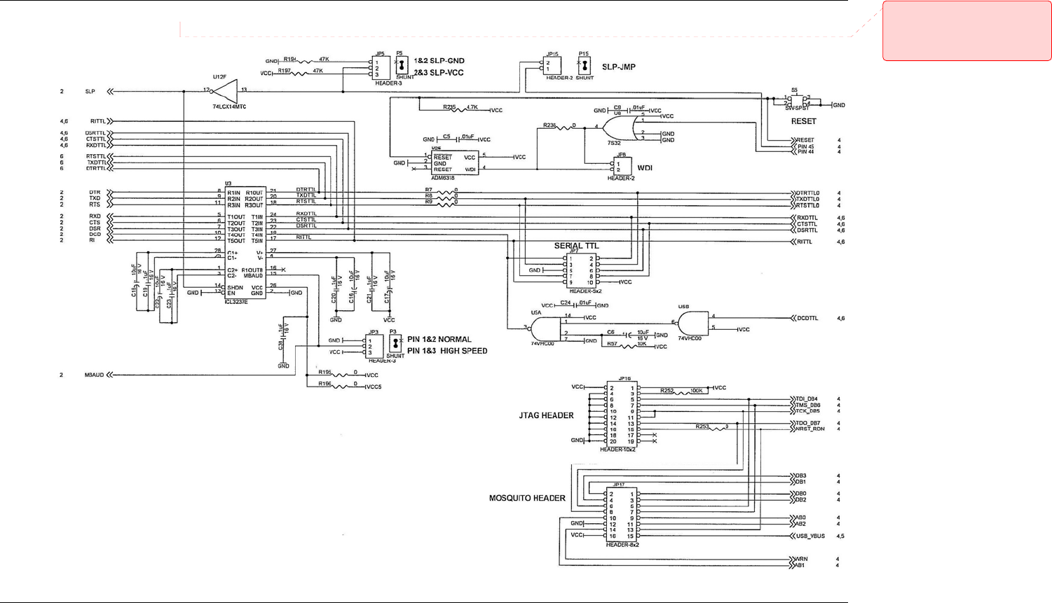
Developer Board Schematics
Comment [DAR10]: Schematics
Board B page 3
Scan0577_000grayscale50percent.gif
(changed from jpg to make the file
size smaller 8/5/09)
Board Revision B
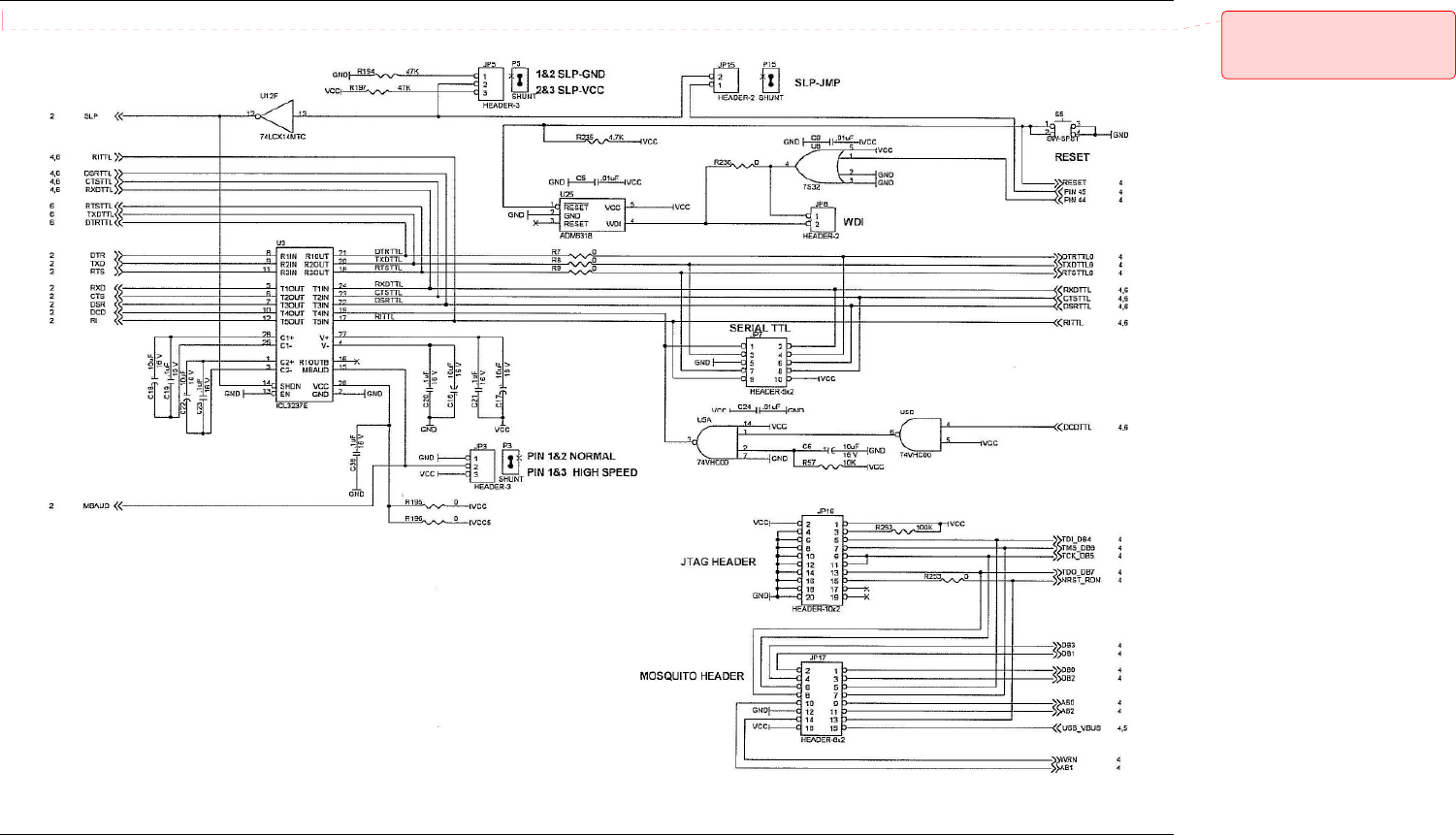
Developer Board Schematics
31
Comment [DAR11]: Schematics
Board B page 4
Scan0575_000grayscale.gif (was jpg
– now a gif for a smaller file 9/5/09)
Board Revision B
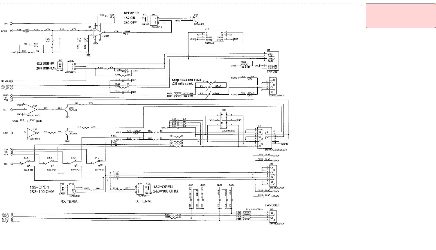
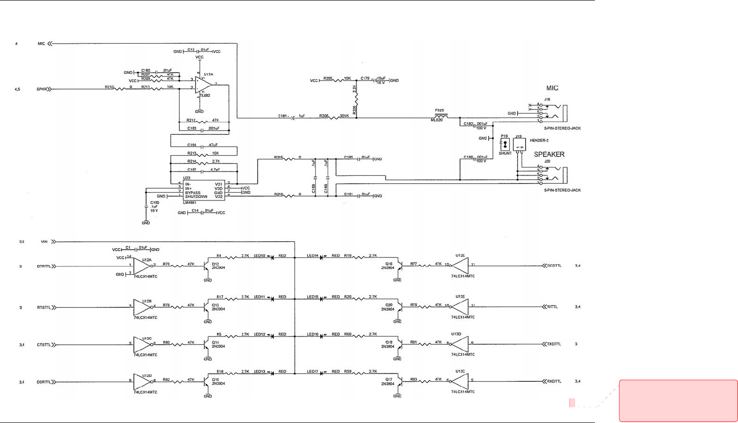
Developer Board Schematics
32
Comment [DAR12]: Schematics
Board B page 5
Scan0574_000grayscale50percent.gif
(was jpg but file was too large. Now
gif 8/5/09)
Board Revision B
Developer Board Schematics
33
Board Revision B
Comment [DAR13]: Schematics
Board B page 6 Scan0573_000.jpg
did not change to gif – file was
already small