Multitone Electronics PLC CS100 2.4GHz Cordless Communication System Base Station User Manual User Guide
Multitone Electronics PLC 2.4GHz Cordless Communication System Base Station User Guide
UserManual.wiki
>
Multitone Electronics PLC
>
CS100 User Manual
>
User Guide
Contents
1.
User Guide
2.
Data sheet
User Guide
Navigation menu
Upload a User Manual
Namespaces
Wiki Guide
HTML
PDF
Info
Views
User Manual
Discussion / Help
Navigation


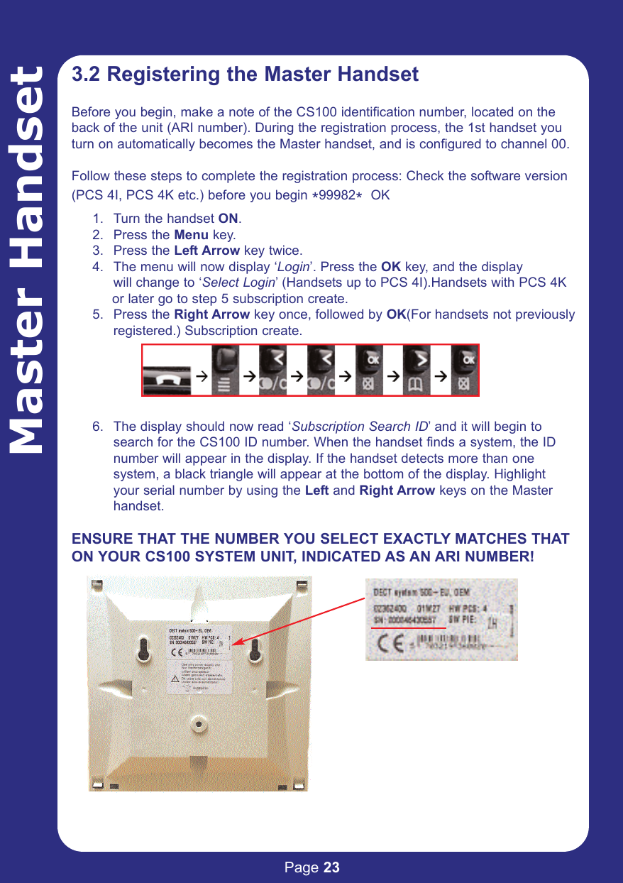
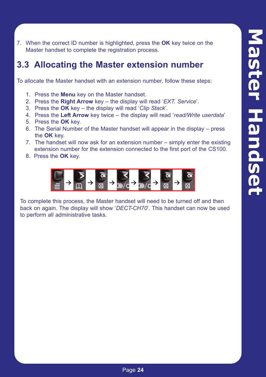
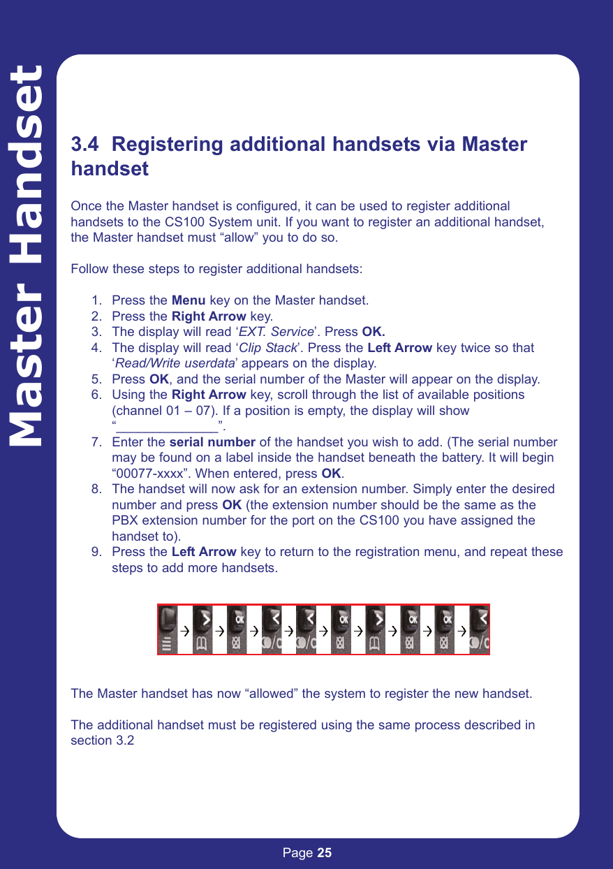
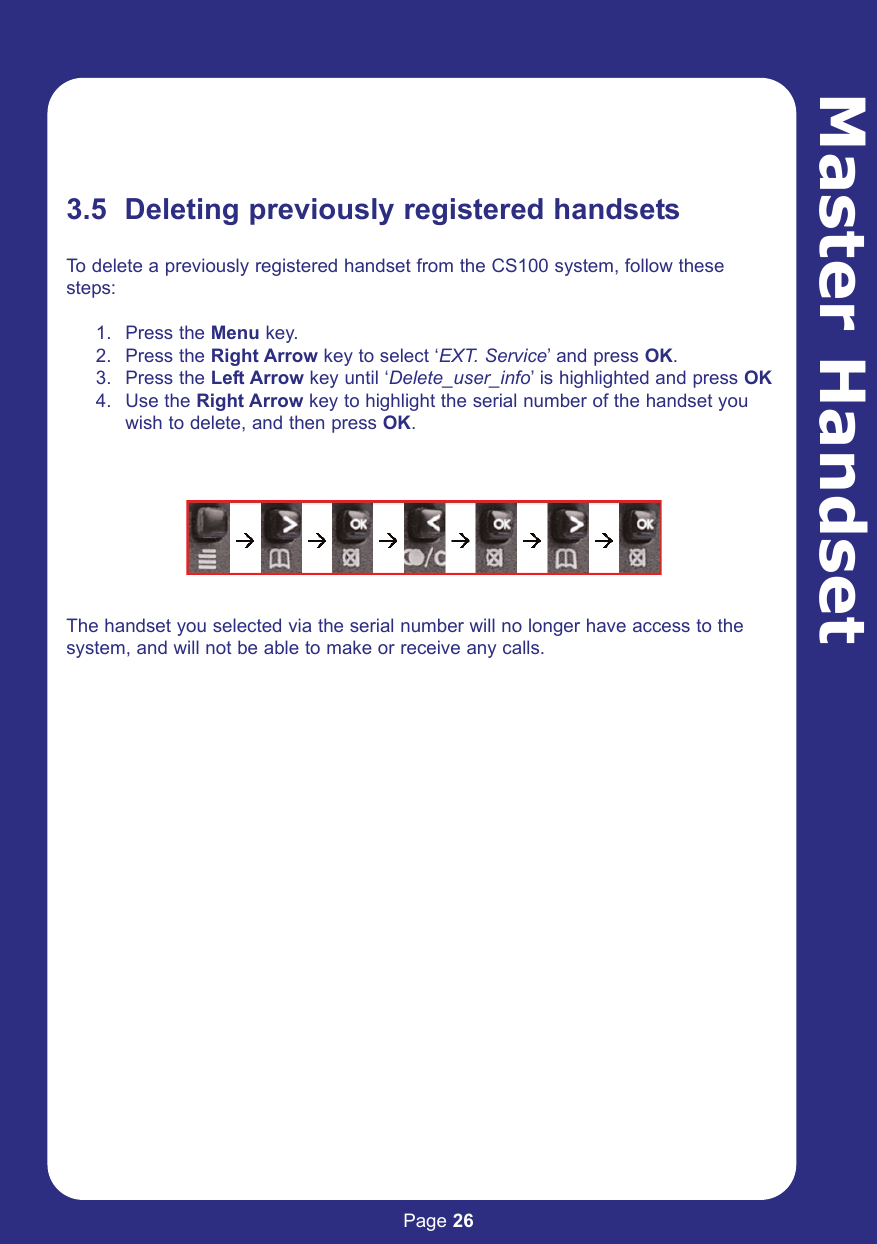
![Page 38PC AdministrationStatus Message LevelUsing the CCFP AdministrationProgram, you can track handsetstatus and call information. This canbe useful for system testing andverification.This information is optional, and youcan configure how much informationis displayed via the Status MessageLevel button in the top menu.Level 0: No Status Messages are returnedLevel 1: Subscription Request is shownLevel 2: Subscription Request and HS (handset) Connection is shownLevel 3: Subscription Request , HS Connection and RFP / IWU Status is shownWhen you set this option to level 1 – 3, the Status Message tab appears inthe CCFP Program. (Note – this option will not appear if you set StatusMessage Level to 0).The Status Message screen provides an overview of the activities that arecurrently being performed by the CS100 System. Using the ‘Seek’ function, you can search for specific types of events.When the CCFP Administration Program is closed the status level is set toLevel 0 automatically. This is done to prevent to many messages “flooding”the CCFP. If the status messages are needed you have to set the[Write Status Level] manually. In order to optimise data-transfer from theCCFP to the PC and vice versa this setting should optimally be set to zero.](https://usermanual.wiki/Multitone-Electronics-PLC/CS100.User-Guide/User-Guide-366577-Page-39.png)