Multitone Electronics PLC CS100 2.4GHz Cordless Communication System Base Station User Manual User Guide
Multitone Electronics PLC 2.4GHz Cordless Communication System Base Station User Guide
Contents
- 1. User Guide
- 2. Data sheet
User Guide

Multitone Electronics plc
Head Office
Multitone House
Shortwood Copse Lane
Kempshott
Basingstoke
Hampshire
RG23 7NL
Tel: +44 (0) 1256 320292
Fax: +44 (0) 1256 462643
E-Mail: Info@multitone.com
www.multitone.com
UK Sales & Service Office and Customer Helpdesk
Unit 33, Geddes House
Kirkton North
Livingston
West Lothian
EH54 6GU
Tel: 01506 418198
Fax: 01506 411711
Multiton Elektronik GmbH
Rosstrasse 11
40476 Dusseldorf
GERMANY
PO Box 320760
vertrieb@www.multiton.de
Multitone Comm.Syst. pty Ltd
Level 5
43-51 Queen Street
Melbourne
Victoria 3000
AUSTRALIA
Service & Installation Agents - U.S. & Canada
Installation and servicing for this equipment, may be obtained from the following companies:-
U.S. Canada
Turn-key Technology Inc. (T.T.I.) Multitone Wireless (Canada)
2500 Main Street Extension 241 Edgeley Bl. Unit 13
Suite 10 Concord
Sayreville Ontario
NJ 08872 L4K 3Y6
Contact: Craig Badrick Contact: Ed Heffernan
Tel: (732) 553 9100 Tel: (905) 760 9696
Fax: (732) 553 9107 Fax: (905) 760 9445
E-mail: cbadrick@turn-keytechnologies.com E-mail: EdHeffernan@multitonewireless.com
CS100 User Guide - 9261-6888 - Issue 1.4
Page 1

Page 2
Contents
CS100 System User Guide
Contents
Page
1. CS100 System Overview Section . . . . . . . . . . . . . . . . . . . . . . . . . . . . 4
1.0 CS100 System Overview . . . . . . . . . . . . . . . . . . . . . . . . . . . . . . . 6
1.1 CS100 System Specifications . . . . . . . . . . . . . . . . . . . . . . . . . . . 7
1.2 Handset Options . . . . . . . . . . . . . . . . . . . . . . . . . . . . . . . . . . 8
1.3 Repeaters / Extended Range . . . . . . . . . . . . . . . . . . . . . . . . . . . 9
2. Equipment Setup and Configuration Section . . . . . . . . . . . . . . . . . . . 10
2.1 System Components . . . . . . . . . . . . . . . . . . . . . . . . . . . . . . . . . . 12
2.2 Guidelines for Installation of the CS100 Base Station . . . . . . . . . . 13
2.3 Preparation for Installation . . . . . . . . . . . . . . . . . . . . . . . . . . . . . 14
2.4 Wiring up the CS100 Master Base Station . . . . . . . . . . . . . . . . . . 17
3. Master Handset Configuration Section . . . . . . . . . . . . . . . . . . . . . . . . 21
3.1 Master Handset Configuration . . . . . . . . . . . . . . . . . . . . . . . . . . . 22
3.2 Registering the Master Handset . . . . . . . . . . . . . . . . . . . . . . . . . 23
3.3 Allocating the Master Handset Extension Number . . . . . . . . . . . . 24
3.4 Registering Additional Handsets via the Master Handset . . . . . . . 25
3.5 Deleting Previously Registered Handsets . . . . . . . . . . . . . . . . . . 26
4. PC Software Configuration Section . . . . . . . . . . . . . . . . . . . . . . . . . . . 27
4.1 Installing the CCFP Administration Software . . . . . . . . . . . . . . . . 28
4.2 Configuring the CCFP Software for the first time . . . . . . . . . . . . . 30
Phone Book . . . . . . . . . . . . . . . . . . . . . . . . . . . . . . . . . . 31
Editing Phone Book . . . . . . . . . . . . . . . . . . . . . . . . . . . . . 32
MSF (Message Service Function) . . . . . . . . . . . . . . . . . . . 33
MSF Status . . . . . . . . . . . . . . . . . . . . . . . . . . . . . . . . . . 34
Registration Screen . . . . . . . . . . . . . . . . . . . . . . . . . . . . . 35
Handset registration . . . . . . . . . . . . . . . . . . . . . . . . . . . . . 36
CCFP Setup . . . . . . . . . . . . . . . . . . . . . . . . . . . . . . . . . . 37
Status Message Level . . . . . . . . . . . . . . . . . . . . . . . . . . . 38
File Menu . . . . . . . . . . . . . . . . . . . . . . . . . . . . . . . . . . 39
Options Menu . . . . . . . . . . . . . . . . . . . . . . . . . . . . . . . . . . 39
Technical Appendix Debug . . . . . . . . . . . . . . . . . . . . . . . . 40
Impedance Setup . . . . . . . . . . . . . . . . . . . . . . . . . . . . . . . 41

Page 3
Contents
Contents (continued)
Page
5. Repeater and Handset Programming . . . . . . . . . . . . . . . . . . . . . . . . . 42
5.1 Start up text . . . . . . . . . . . . . . . . . . . . . . . . . . . . . . . . . . 42
5.2 Instructions for Installation and Configuration . . . . . . . . . . . . . . . . 43
Determining location of repeaters . . . . . . . . . . . . . . . . . . . . . . 44
5.3 Setting up Repeaters . . . . . . . . . . . . . . . . . . . . . . . . . . . . . . . . . . 45
5.4 Powering up and Testing . . . . . . . . . . . . . . . . . . . . . . . . . . . . . . . 46
5.5 Kirktool Software Installation . . . . . . . . . . . . . . . . . . . . . . . . . . . . 47
Communicating with the Kirktool Software . . . . . . . . . . . . . . . 48
5.6 Registering a Repeater . . . . . . . . . . . . . . . . . . . . . . . . . . . . . . . . 50
5.7 Establishing Repeater Jumps . . . . . . . . . . . . . . . . . . . . . . . . . . . 52
6. Frequently asked Questions . . . . . . . . . . . . . . . . . . . . . . . . . . . . . . . . 53
7. CS100 Messaging . . . . . . . . . . . . . . . . . . . . . . . . . . . . . . . . . . 55
8. Technical Specifications Section . . . . . . . . . . . . . . . . . . . . . . . . . . . . 57
8.1 CS100 System features for all 8 Handset lines . . . . . . . . . . . . . . 57
8.2 IWU Setup for CCFP Administration Program . . . . . . . . . . . . . . . 58

Page 4
System Overview
CS100 System Overview
1. CS100 System Overview
1.1 CS100 System Specifications
1.2 Handset Options
1.3 Repeaters / Extended Range

Page 5
System Overview
Technical Approvals:-
This equipment is compliant with the following regulations, according to country of commission:-
Europe - Radio & Telecommunications Terminal Directive 1999/5/EC
(see accompanying leaflet);
United States - FCC Part 15; UL1950
Canada - RSS 210; CAN 22-950
US/Canada - This device complies with Part 15.247 of the FCC Rules & Regulations and
Industry Canada Standard RSS210. Operation is subject to the following two conditions: (1) this
device may not cause harmful interference, and (2) this device must accept any interference
received, including interference that may cause undesired operation.
Any modifications to this equipment not expressly authorised by Multitone, could void the user’s
authority to operate the equipment.
Safety & Product Information
Before using your equipment, read this User Guide and follow any warnings and instructions.
Do not install the equipment near any sources of water, or in damp conditions. Use only the
power adapter provided, or a recommended equivalent and do not overload wall outlets and
extension cords, as this can result in fire, or electrical shock. If in doubt, consult your dealer or
local power company.
Do not use the equipment where there is a danger of electrically ignited explosions eg. gas leaks,
or petroleum vapour. Do not expose the equipment to direct sunlight for long periods, or exces-
sive heat and moisture. Do not attempt to disassemble the equipment. If it has been adversely
exposed to liquid, dropped or damaged, or does not operate as intended, please refer to qualified
service personnel. Use only a damp cloth for cleaning. Avoid liquid, or aerosol cleaning agents.
US/Canada :- Operation of the equipment in the proximity of microwave appliances or radio/TV
equipment, may be subject to interference.
NB Unless special provision has been made, this equipment will not operate in the event of a
power blackout. Keep a back-up phone for emergencies.
Specific Absorption Rate (SAR) Information
This cordless telephone equipment consists of radio transmitters and receivers. It has been
designed not to exceed the recommended limits for exposure to radio-frequency (RF) energy, as
set by the U.S. Federal Communications Commission and Industry Canada/Health Canada. The
measured SAR levels from this equipment, is below the recommended safety limit of
1mW/sq.cm., for uncontrolled exposure to equipment operating @ 2.4GHz. However, it is
recommended that an operational distance of >20cm is maintained between personnel and the
equipment, other than for servicing purposes.
Page 6
System Overview
1. CS100 System Overview
A cordless telephone system with
excellent range allows you to
make or receive calls even when
you are away from your desk
Coverage can be extended at any
time by simply installing a
Repeater
Up to 6 people can make or
receive calls at the same time
The CS100 System is simple to
install and configure
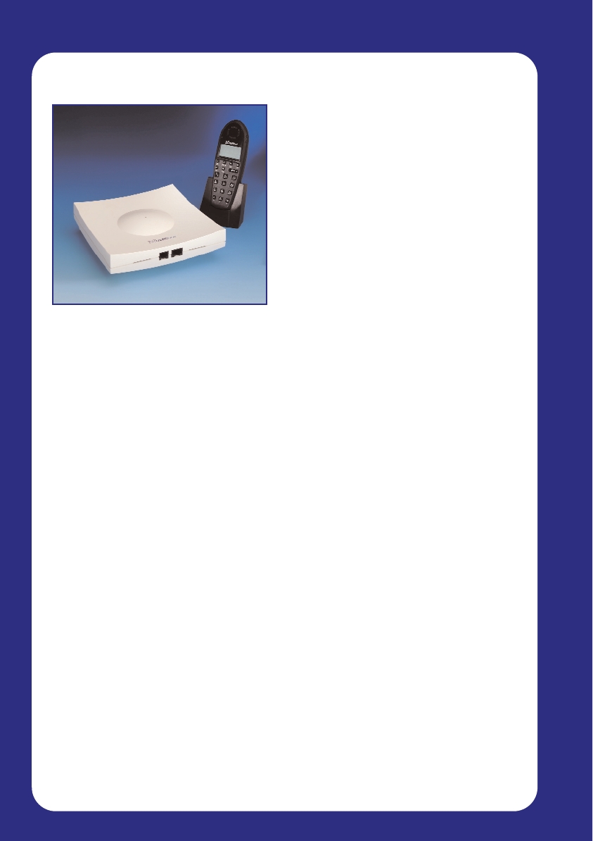
The CS100 System is a small business mobile communications solution. It
connects up to 8 wireless handsets direct to your existing Telephone
System, providing your workforce with the ability to communicate from
anywhere within CS100 system Master or repeater radio coverage.
By adding Repeaters at strategic locations, coverage can easily be
extended to suit your needs.
A repeater allows the user to roam over larger areas without losing the call.
This feature rich mobile solution means that your staff are no longer tied to
their desks, and can talk to your customers whilst on the move. This will
improve productivity, morale, and customer satisfaction.
The CS100 is an OEM branded product that can be used with Multitone
CH70 Handsets. It can also be used with Multitone’s messaging products
P318 & access integrator. The messaging products are designed for
connection to moving contact alarms which can be used to trigger security
alerts, alarms or similar messaging alerts to CH70 handsets. Access
integrator connects to a LAN, and may be used to message single handset
users or teams of users. In addition both products have serial ports that can
be connected to fire alarms, or other data inputs (Manufacturing/processing)
Contact sales support or www.multitone.com for more details.
Page 7
System Overview
1.1 CS100 System Specifications
Range – up to 300m
Handsets can be registered via a
Master handset – or using a PC
Supports up to 8 handsets
6 handsets can make or receive
calls simultaneously
Measurements – 150 x 150mm
Connects to the Host PABX by a
twisted pair standard telephone cable
Base unit can be placed up to 7000
metres from the switchboard
depending on PABX limits
LED lights to indicate operations
status
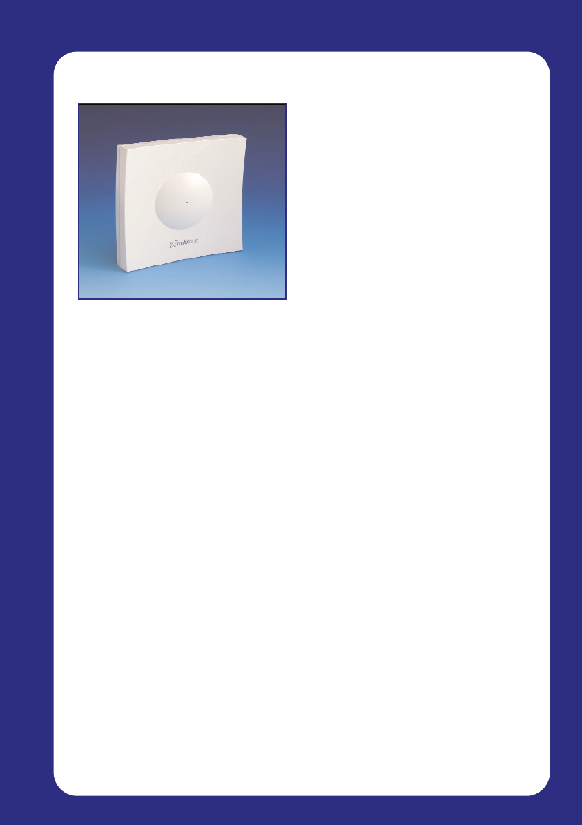
The CS100 is a single cell System that allows up to 8 wireless handsets to be
connected, covering an area of up to 300 metres from where it is placed. It is an
adjunct to a PABX for 8 A/B connections and a RS232 computer programming
interface.
Up to 6 repeaters can be used with a maximum of 3 of the repeaters ‘daisy chained’
to extend the coverage area. As you move outside the range of the base unit,
coverage will be handed over to the repeater so that the call doesn’t get dropped.
A computer is NOT required to run the CS100 system, although system
administration software is supplied and recommended. Handsets can be logged in
to the system using the ‘Master’ handset, which is configured during installation.
Analogue A/B Line Features
The inter working unit creates the interface between 8 analogue lines and the digital
lines in the CS100 system. The A/B lines are all galvanically isolated from the rest of
the System and from each other.
Features for all 8 lines:
DTMF transmit and Single tone receive
DTMF receive and Single tone transmit (Option)
Echo cancelling
Echo suppression
Pulse generating
Ringing detection
Loop break
Galvanic isolation
Page 8
System Overview
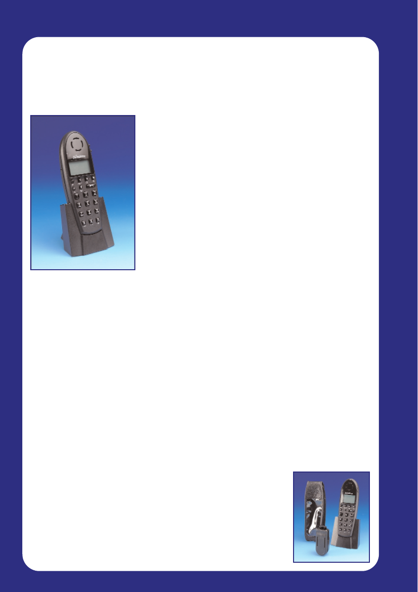
1.2 Handset options
Note: the handset used in this example is the Multitone CH70. Other handsets are
compatible with the CS100 System, although operating instructions may vary.
Multitone cannot give support for 3rd party handsets - for more information see
chapter 6.
Key features:
DECT based technology
121 grams
145 x 50 x 23 (mm)
10 hours active talk-time
90 hours standby
65 number telephone memory
Silent vibrate alert option
Automatic call answering
Large LCD for text messaging with backlit display
Caller ID - between DECT handsets
Headset jack for ‘Hands-free’ option
GAP/CAP compliant
The CH70 cordless handset is compact, robust and simple to use. Its lightweight
and slim design makes this the perfect pocket phone, without compromising on
performance or features.
The CH70 can be used independently, or together with a standard desk phone.
Sharing the same telephone number means that there are no new extension
numbers to remember, so people will always be able to contact you at the one
number. You can set either phone to ring (or both!) and transferring a conversation
from one phone to another is effortless.
This phone is purpose built for use in many working situations. For example,
someone working in a noisy environment may use the vibrate module to ensure they
know when a call is incoming; a machine operator may use the hands-free option
with auto-answer capabilities. An ear defender headset can also be used.
A range of accessories is available to support this phone, and increase functionality.
These include:
Headset
Ear defenders
Belt clip
Holster
Hands free docking station
Page 9
System Overview
1.3 Repeaters / Extended Range
Key Features:
Extend area of Radio coverage easily
and within minutes
Eliminate areas of poor coverage
Range of up to 300 metres
Provide external coverage - useful
for car parks or other outdoor areas
‘Daisy Chain’ up to 3 Repeaters to
cover larger areas, such as a
warehouse or extended office area
The CS100 system base unit has a coverage range of up to 300 metres.
However, this can be easily extended to suit your needs by adding
‘Repeaters’.The range of the base Station and repeater depends upon the
working environment.
Repeaters are used to increase the range of coverage over a larger area.
If you find the CS100 system base unit coverage does not reach a certain
part of your building, you can simply add a repeater near the outside range
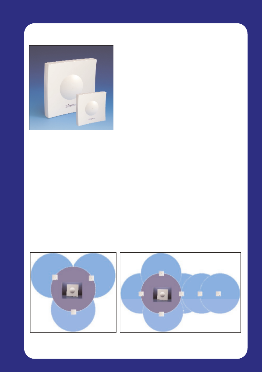
of the base unit, thus eradicating signal drops and weak areas (Figure 1).
The CS100 system can support up to 6 Repeaters, up to 3 of which can be
‘daisy chained’ to form a long coverage area – ideal for large warehouses
(Figure 2).
Each repeater or repeater chain has a maximum of 2 speech channels.
Figure 1: 3 repeaters are used to extend Figure 2: 3 repeaters have been chained to extend coverage
coverage over a much larger area over a long area, such as an open plan office or warehouse.

Page 10
Equipment Installation
Equipment Installation
2. Equipment Setup and Configuration
2.1 System Components
2.2 Guidelines for Installation
2.3 Preparation & Installation of the CS100 Base Station
2.4 Wiring up the CS100 Master Base Station
2.5 Powering up and Testing

Page 11
Equipment Installation
This page has intentionally been left blank.

Page 12
Equipment Installation
2. Equipment Setup and Configuration
2.1 System Components
The following components are supplied with the CS100 Base Station
system:
1 x CS100 Base Station unit
1 x PSU - 3 metre cable
1 x Technical user guide (this guide)
2 x screws and rawl plugs
The PC Programming cables for the CS100 Base Station and Repeaters
are sold separately.
A choice of 2 programming cables are available
0361-6928 9 way D - RJ45
0361-6929 25 way D - RJ45
Programming software can be down loaded from www.multitone.com
You will require the following tools to complete the installation:
Wire cutters
Small Philips screwdriver
Drill & suitable bits

Page 13
Equipment Installation
2.2 Guidelines for Installation of the CS100
Base Station
When deciding the location of the CS100 Base Station, consider what area
of your office or work place you need the most coverage. This should also
take into account the number of people who will be using a handset within a
given area. Try to place the Base Station as centrally as possible to ensure
maximum efficiency, unless external coverage is required.
An ac power outlet socket must be available within 3 metres of the fixing
point of the CS100 Base Station.
Keep the Base Station 1.5 metres clear from any electrical equipment such
as computers and fax machines. These devices can cause Electro-Magnetic
Interference (EMI), weakening the radio signal.
The Base Station must be kept in an area where the temperature is
maintained within the limits of 0 - 50ºC. The air must not be damp or humid,
and must be free from water spray or a conductive/corrosive atmosphere
and out of direct sunlight.
In order to get the best signal coverage, place the Base Station as high as
possible, but at least 4” (10 cm) from the ceiling or any metallic surfaces.
Also, foil insulated plasterboard or any other similar foil insulation may affect
performance.
For information on testing the coverage and signal strength, see section 5.4
– ‘Powering up and Testing’.

Page 14
Equipment Installation
2.3 Preparing for Installation
Before you begin to install and configure your new CS100 system it is
recommended that you take note of the following points to ensure a smooth
installation.
Radio Coverage
Transmission from the CS100 base unit can achieve a coverage radius of
300m in clear space. However the distance that will be achieved in your
installation depends very much on the location you choose for the Base unit
and any repeaters you install. Coverage from a base unit in the wrong
location could be less than 10m. Thick walls, dense concrete, tinted glass
with a high metal content and metal clad buildings, all may attenuate the
signal.
If you are concerned that you may have a coverage problem then a
coverage survey should be carried out prior to installation. A survey kit can
be rented/purchased from your system supplier or carried out using the
CS100 and the master handset.
Choosing a location for the CS-100 base unit
The CS100 can be placed up to 7.5km (subject to Host PABX) from
the PBX. Mains power should be within 3 metres. The Unit should be
Placed in the geographic centre of the area to be covered unless:
(a) The majority of users would be located out of range of the
CS100 base unit.†
(b) The location is External.
(c) The unit would be located in a hostile environment
(such as refrigerated room).
The Unit should be Located at Least 10cm away from any metal surface
and the same distance from the ceiling or corners of the room. The more
free space around the unit the better.
Choose a location that is free of any obstructions (such as racking or filing
cabinets).
Avoid locating CS100 in the void area of suspended ceilings.
Although a high location is good it may be necessary in the future to
connect a PC to the CS100 for administration or maintenance. In this case
locate within 3 metres of the PC or Laptop position.
If an External location is chosen for siting the unit please call your supplier
for further advice before proceeding with the installation.
† See Section2.2

Page 15
Equipment Installation
Choosing a location for a repeater.
It is important that a repeater is located within the good coverage area of
the base unit. Failure to do so will result in apparent poor reception for any
handset connecting to the repeater.
The Unit should be Located at Least 10cm away from any metal and the
same distance from the ceiling or corners of the room. The more free space
around the unit the better. Choose a location that is free of any obstructions
(such as racking or filing cabinets). Although a high location is good it may
be necessary in the future to connect a PC to the CS100 for administration
or maintenance.
Avoid locating Repeater in the void area of suspended ceilings.
If an External location is chosen for siting the unit please call your supplier
for further advice before proceeding with the installation.
Unpacking your CS100 System
Check all equipment for damage, and correct delivery
Assemble all handsets and chargers ready for battery charging
Installation and Configuration
Charge all handset batteries
Determine the location for the CS100 Base Station
Register the Master handset and all other user handsets
Test CS100 Base Station coverage
Assuming coverage is OK install the CS100 Base Station
Determine the location for any Repeaters
Register and configure Repeaters
Test coverage handled by Repeaters
Assuming coverage is OK install any Repeaters
Verify system operation and installation successful

Page 16
Equipment Installation
* Charging your handset battery packs
When supplied, your handset battery pack will contain only a low residual
charge. To ensure reliable operation, ensure you fully charge the battery
packs. For the initial charge, allow up to 14 hours to ensure the battery is fully
charged. This process will take approximately 3½ hours (from fully discharged
to fully charged) during normal operation.
THIS PRODUCT CONTAINS NI MH BATTERIES. THESE BATTERIES MUST
BE RECYCLED, OR DISPOSED OF PROPERLY. DO NOT DISPOSE OF IN
FIRE, OR MUNICIPAL WASTE. CHECK WITH LOCAL CODES FOR
SPECIAL DISPOSAL INSTRUCTIONS.
Use only specified batteries in the handset, as other battery types eg Alkaline
or Lithium, may lead to hazardous conditions. Do not use non-specified
charging devices, as this could damage the batteries. Periodically clean the
charge contacts on both the handset and charger.
Exercise care when handling batteries, to avoid shorting contacts with conduc-
tive materials such as jewelry, or keys. Do not open or mutilate the batteries,
as the electrolyte is corrosive and toxic.
Batteries may heat-up slightly during charging. This is normal and not
dangerous.
(See also handset user guide).
Page 17
Equipment Installation
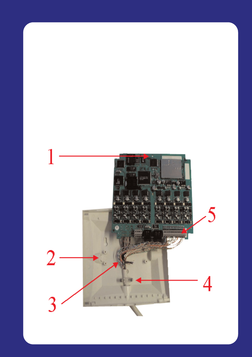
2.4 Wiring up the CS100 Base Station
To wire up the CS100 Base Station, remove the front facia by gently
releasing the 4 clips on the rear of the unit. At the top of the circuit board,
there is a screw keeping the board in place – remove this screw to release
the board from the case. Follow anti-static precautions while handling the
PCB. Now follow these steps:
1. Carefully remove the circuit board from the housing
2. Cable can be inserted through any of the 4 passages in the base
of the housing. Remove the ‘Break out’ tab from the cable
passage convenient to your installation
3. Insert the cabling through the hole
4. Secure the cable using the bracket and screws provided
5. Connect the wires into the connector at the bottom of the circuit
board
Page 18
Equipment Installation
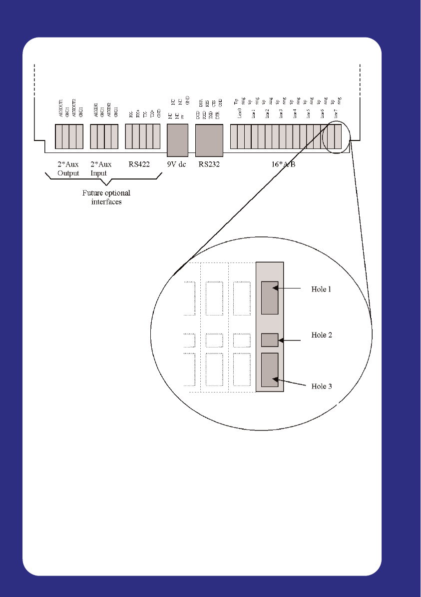
The connectors are laid out as follows:
The connector for the 9V dc is a 6/6 modular plug, whilst the connector for
the RS232 is an 8/8 modular plug. The other connectors are fast
connectors. Release of the internal spring can be achieved by either
pushing a 0,5 mm or similar small probe into hole 1 or 2 while pushing the
stripped wire into hole 3. Check that the wire is secured by pulling the wire
gently.

Page 19
Equipment Installation
2.5 Powering Up and Testing
CS100 LED Display
When the CS100 Base Station is receiving a supply of power, the LED
display will give you basic information as to its status.
Green Normal operation
Red Fault
Flashing red Subscription mode
Testing Base Station / Repeater Signal Coverage
The radio coverage provided by the CS100 Base Station can be tested by
using one or more handsets which has been registered to the system
(See section 3.1 – ‘Registering the Master Handset’).
When carrying out this test, the handset must be ‘Off Hook’ in field-test
mode. To set the handset to this mode, press “ *99981*” followed by OK.
The display will now change to show the following:
RPN – The first number is the Base Station / Repeater that the handset is in
communication with. The second number is the current preferred choice
Repeater for handover of a call if the user is moving. These numbers will
change as you move around.
Q52 – This is the audio quality indicator. A number between 60 and 64 is
acceptable, with 64 being the best. Anything below 60 and the audio quality
may deteriorate.This should also be checked by setting up a voice connec-
tion to check the speech quality.
RSSI – This stands for Received Signal Strength Indicator, and is a
measure of the received signal from the Base Station or Repeater. This is
used to determine when to ‘Hand Over’ a call. These readings are relative
to each handset, and so variations between handset readouts are normal.
RPN: 00 02
Q52: 64
RSSI: 55 40

Page 20
This page has intentionally been left blank.

Page 21
Master Handset
Master Handset
3. Master Handset Configuration
3.1 Configuring the Master Handset
3.2 Registering the Master Handset
3.3 Allocating the Master Extension number
3.4 Registering additional handsets via the Master Handset
3.5 Deleting previously Registered Handsets
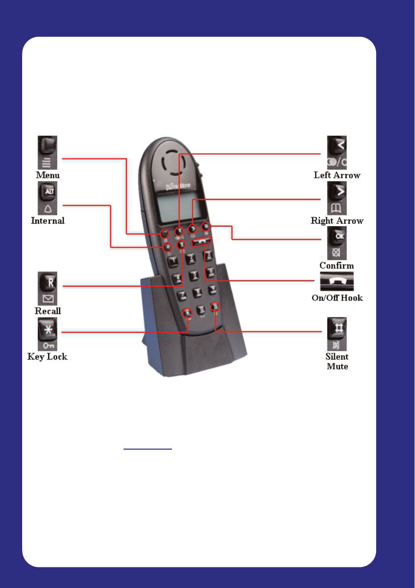
Page 22
Master Handset
3.1 Master Handset Configuration
Note: Administrative tasks may also be carried out using the System
Administration software on any PC or Laptop running Microsoft Windows
95, 98 and 2000. This is recommended.
Software can be downloaded from www.multitone.com
The Master Handset
When the CS100 system powers up, it will automatically go into registration
mode for a period of 15 minutes. During this time, you can register your
‘Master’ handset, which will be used for the following administrative
functions:
Allocating master extension number
Registering additional handsets via Master handset
Deleting previously registered handsets
Registering a Repeater
Establishing Repeater jumps (Repeaters in a chain)
Page 23
Master Handset
3.2 Registering the Master Handset
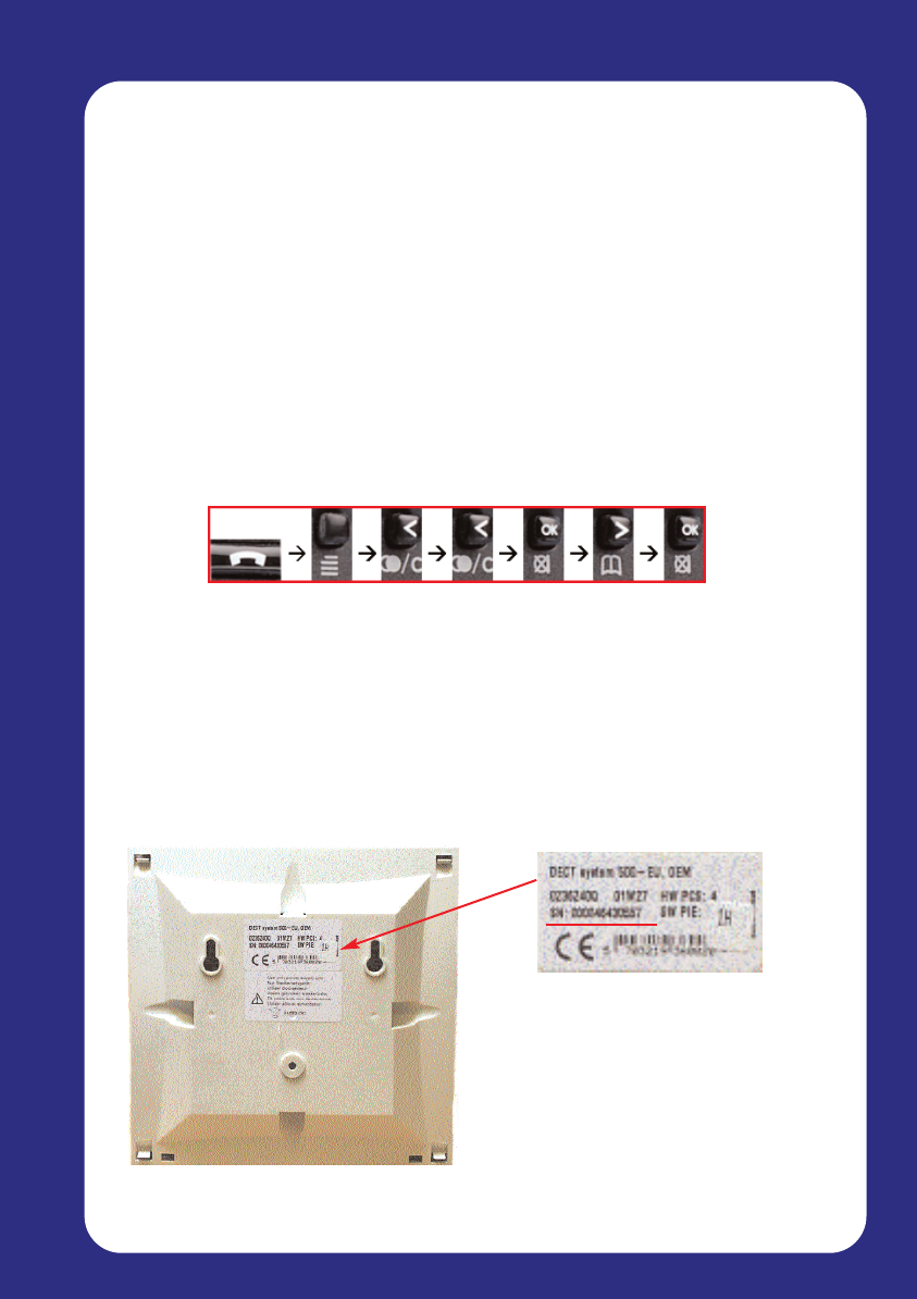
Before you begin, make a note of the CS100 identification number, located on the
back of the unit (ARI number). During the registration process, the 1st handset you
turn on automatically becomes the Master handset, and is configured to channel 00.
Follow these steps to complete the registration process: Check the software version
(PCS 4I, PCS 4K etc.) before you begin *99982*OK
1. Turn the handset ON.
2. Press the Menu key.
3. Press the Left Arrow key twice.
4. The menu will now display ‘Login’. Press the OK key, and the display
will change to ‘Select Login’ (Handsets up to PCS 4I).Handsets with PCS 4K
or later go to step 5 subscription create.
5. Press the Right Arrow key once, followed by OK(For handsets not previously
registered.) Subscription create.
6. The display should now read ‘Subscription Search ID’ and it will begin to
search for the CS100 ID number. When the handset finds a system, the ID
number will appear in the display. If the handset detects more than one
system, a black triangle will appear at the bottom of the display. Highlight
your serial number by using the Left and Right Arrow keys on the Master
handset.
ENSURE THAT THE NUMBER YOU SELECT EXACTLY MATCHES THAT
ON YOUR CS100 SYSTEM UNIT, INDICATED AS AN ARI NUMBER!
Page 24
Master Handset
7. When the correct ID number is highlighted, press the OK key twice on the
Master handset to complete the registration process.
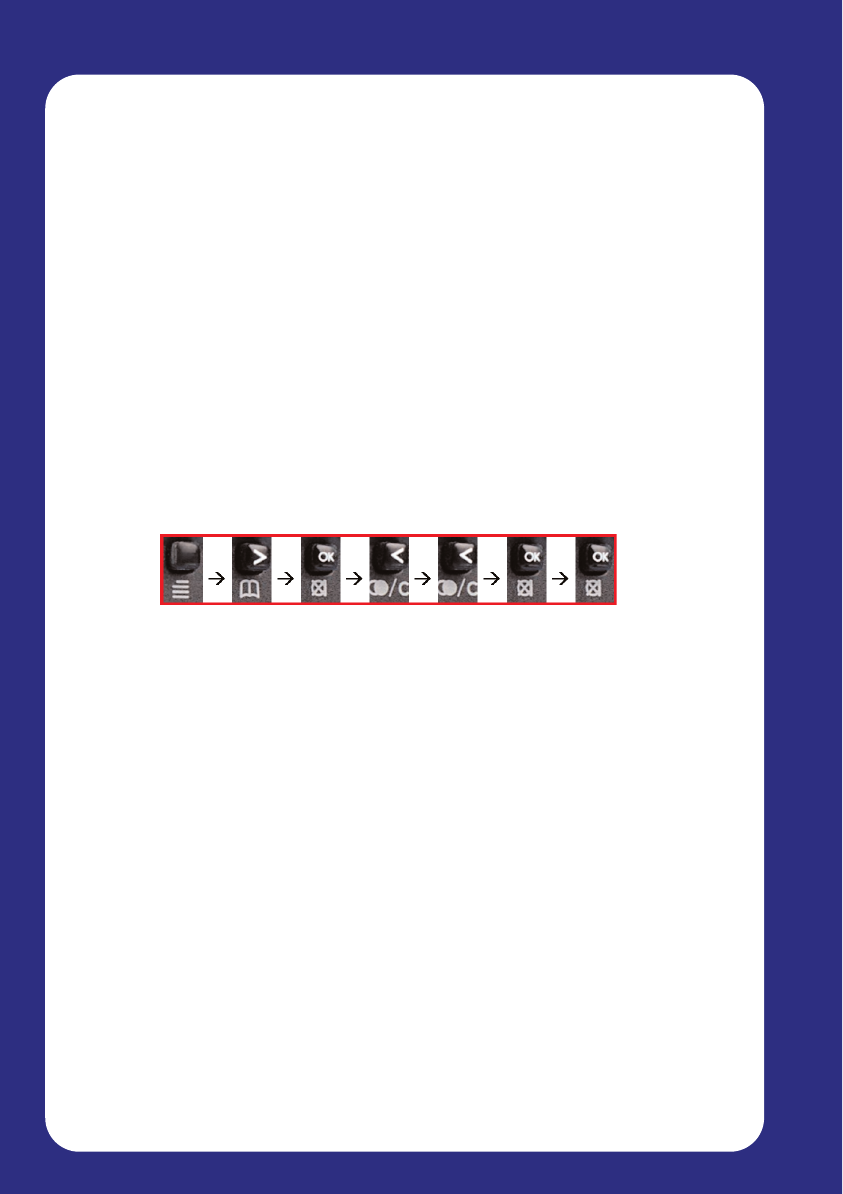
3.3 Allocating the Master extension number
To allocate the Master handset with an extension number, follow these steps:
1. Press the Menu key on the Master handset.
2. Press the Right Arrow key – the display will read ‘EXT. Service’.
3. Press the OK key – the display will read ‘Clip Stack’.
4. Press the Left Arrow key twice – the display will read ‘read/Write userdata’
5. Press the OK key.
6. The Serial Number of the Master handset will appear in the display – press
the OK key.
7. The handset will now ask for an extension number – simply enter the existing
extension number for the extension connected to the first port of the CS100.
8. Press the OK key.
To complete this process, the Master handset will need to be turned off and then
back on again. The display will show ‘DECT-CH70’. This handset can now be used
to perform all administrative tasks.
Page 25
Master Handset
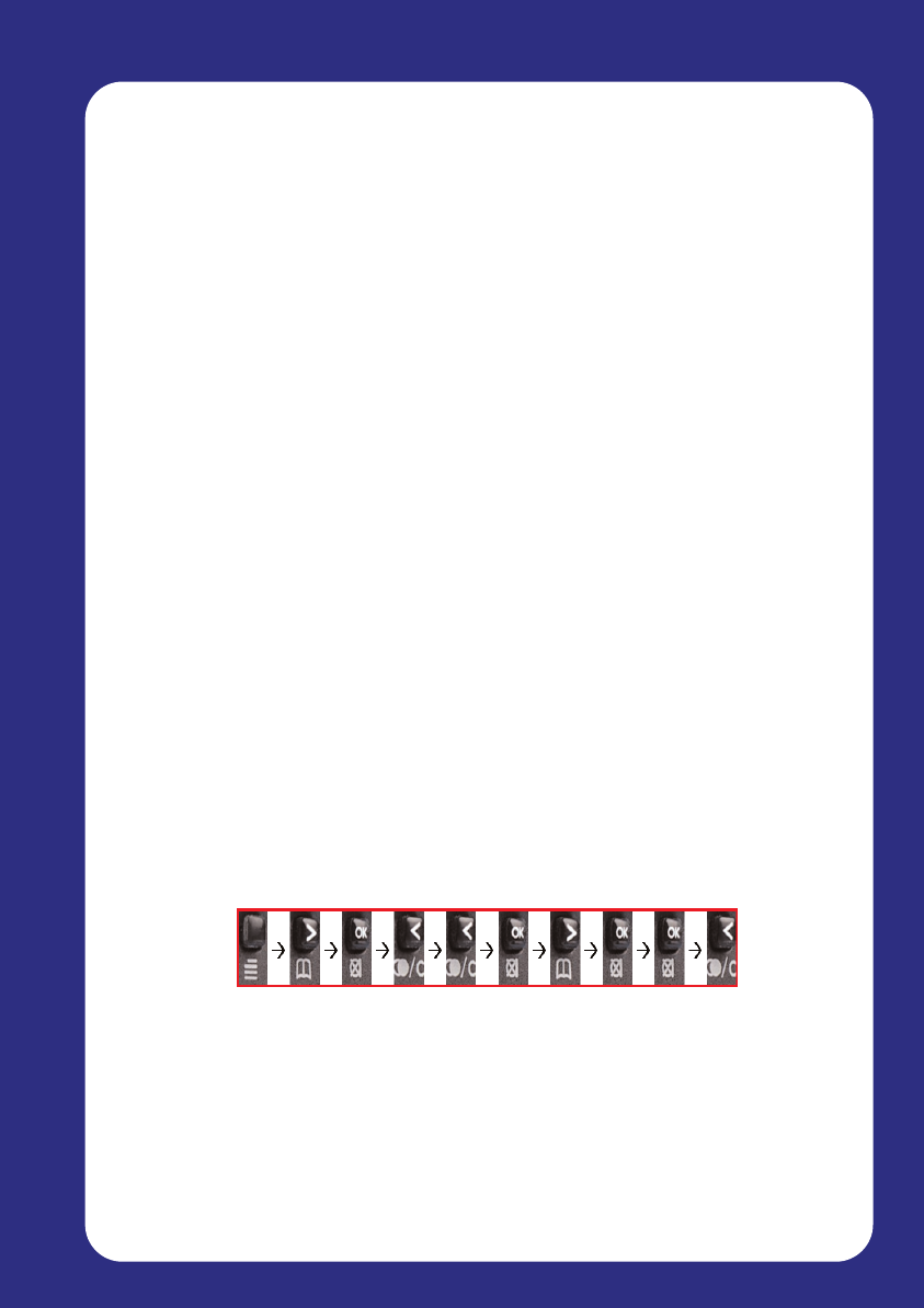
3.4 Registering additional handsets via Master
handset
Once the Master handset is configured, it can be used to register additional
handsets to the CS100 System unit. If you want to register an additional handset,
the Master handset must “allow” you to do so.
Follow these steps to register additional handsets:
1. Press the Menu key on the Master handset.
2. Press the Right Arrow key.
3. The display will read ‘EXT. Service’. Press OK.
4. The display will read ‘Clip Stack’. Press the Left Arrow key twice so that
‘Read/Write userdata’ appears on the display.
5. Press OK, and the serial number of the Master will appear on the display.
6. Using the Right Arrow key, scroll through the list of available positions
(channel 01 – 07). If a position is empty, the display will show
“______________”.
7. Enter the serial number of the handset you wish to add. (The serial number
may be found on a label inside the handset beneath the battery. It will begin
“00077-xxxx”. When entered, press OK.
8. The handset will now ask for an extension number. Simply enter the desired
number and press OK (the extension number should be the same as the
PBX extension number for the port on the CS100 you have assigned the
handset to).
9. Press the Left Arrow key to return to the registration menu, and repeat these
steps to add more handsets.
The Master handset has now “allowed” the system to register the new handset.
The additional handset must be registered using the same process described in
section 3.2
Page 26
Master Handset
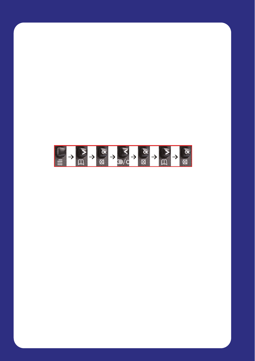
3.5 Deleting previously registered handsets
To delete a previously registered handset from the CS100 system, follow these
steps:
1. Press the Menu key.
2. Press the Right Arrow key to select ‘EXT. Service’ and press OK.
3. Press the Left Arrow key until ‘Delete_user_info’ is highlighted and press OK
4. Use the Right Arrow key to highlight the serial number of the handset you
wish to delete, and then press OK.
The handset you selected via the serial number will no longer have access to the
system, and will not be able to make or receive any calls.

Page 27
PC Configuration
4. PC Software Configuration
4.1 Installing the CCFP Administration Software
4.2 Configuring the CCFP Software for the first time
Phone Book
Editing Phone Book
Registration Screen
CCFP Setup
MSF
MSF Status
Status Message Level
File Menu
Options Menu
Debug
Impedance Setup
PC Configuration
Page 28
PC Configuration
4. PC Configuration
The CS100 System CCFP Administration software is available to download
from our website ‘www.multitone.com’. This is a professional tool for
programming the CS100 system for best performance. This software may
be updated from time to time.
You can use the CCFP Software to input user information, and for
configuring the CS100 to match the parameters of your connected PABX. It
also contains diagnostic utilities to help with fault finding and
troubleshooting.
The CCFP Software has an extremely useful help file that will explain
in more detail some of the options outlined in this user guide.
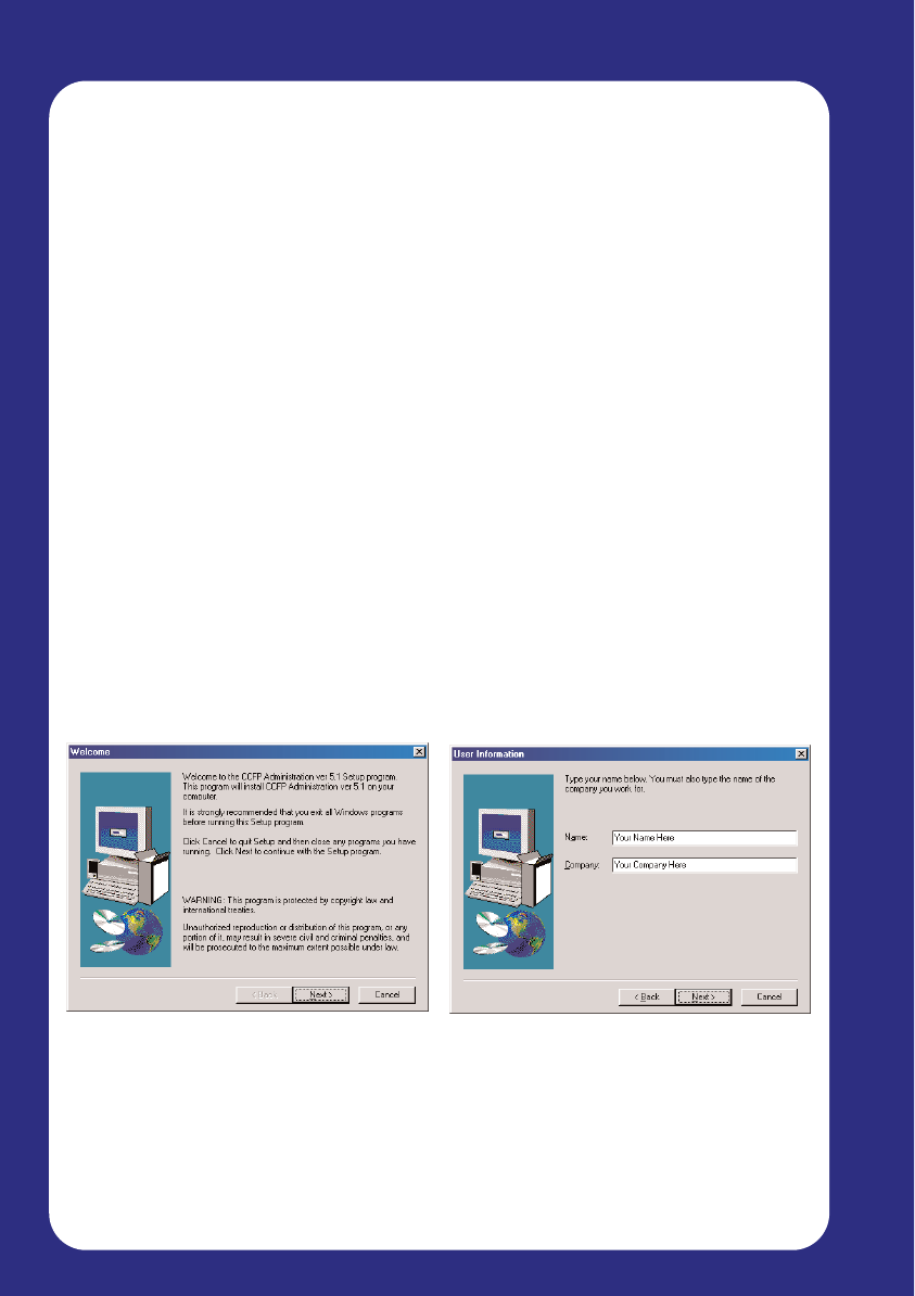
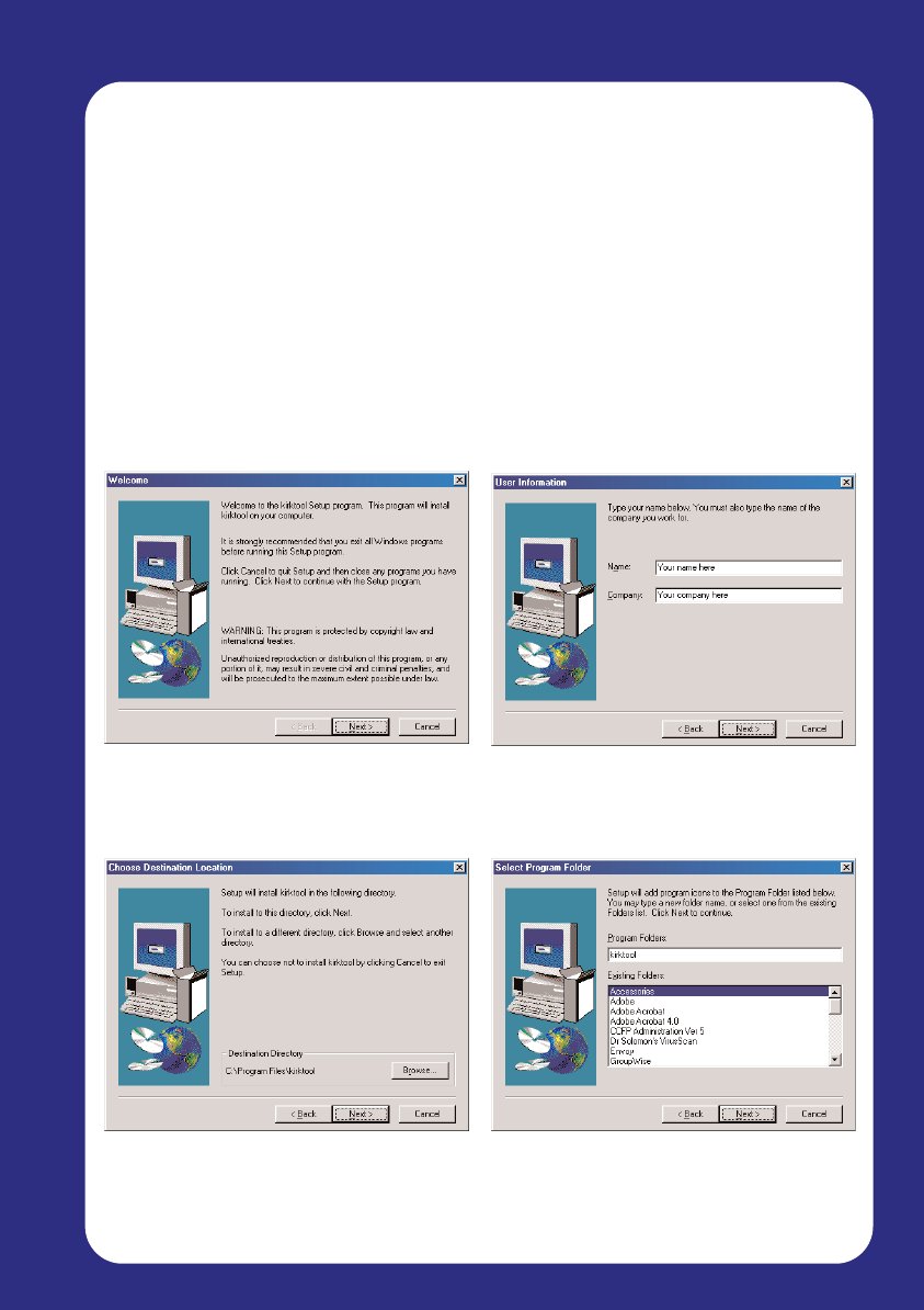
4.1 Installing the CCFP Administration Software
The latest version of software is Revision 8.3 (Jan 2003)
After downloading the CCFP Administration software to a temp directory
UnZip and follow the on screen installation instructions.
1. To begin the software installation
process, click Next
2. Enter your name and company
details, and click Next
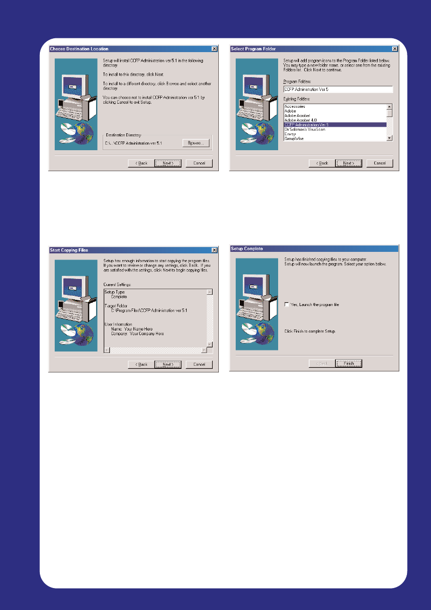
Page 29
PC Configuration
3. You can now specify in which
directory to install the software.
The default is c:\Program Files –
to accept this, click Next
5. Before the files are copied to
your computer, verify the details
you have provided. If you are
satisfied, click Next. Otherwise,
use the Back button to make any
changes
4. The installation will add shortcut
icons to your start menu. This
can be organised to suit your
menu structure. Click Next to
continue
6. The installation is now complete,
and the software has been
copied to the directory you
specified. Click Finish to return
to your desktop
The software is now available from the Start menu at:
Start
Program
CCFP Administration Version X.X
CCFP Administration
Note:
The latest version of the software is available from the Multitone web site.
Page 30
PC Configuration
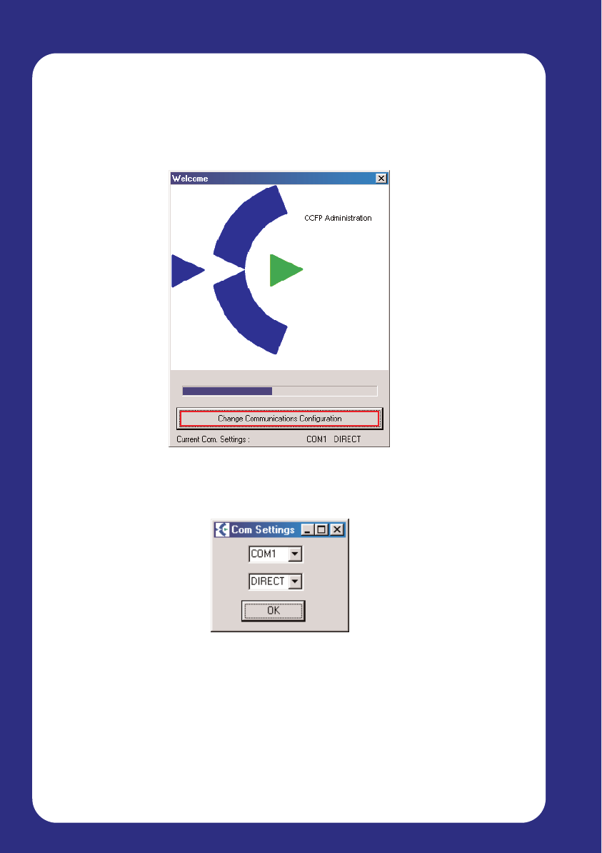
4.2 Configuring CCFP for the first time
When you first load the CCFP Administration software on your computer, it
will automatically attempt to configure the connection settings to the CS100
Base station. The following screen will appear as this happens:
By default the program looks for a connection on COM1 via a Direct
Connection. If these are not the correct settings, you can click on the
‘Change Communications Configuration’ button.
Using this settings window, you can select between the available COM ports
on your computer, and also between Direct Connection or Modem
Connection.
Direct Connection: Connection directly from the CS100 System to the PC
Direct connection is limited to 3 metres between the CCFP or 5 metres
using a modem driver.
Modem Connection: PC remotely accesses the CS100 System via the
telephone system.
Page 31
PC Configuration
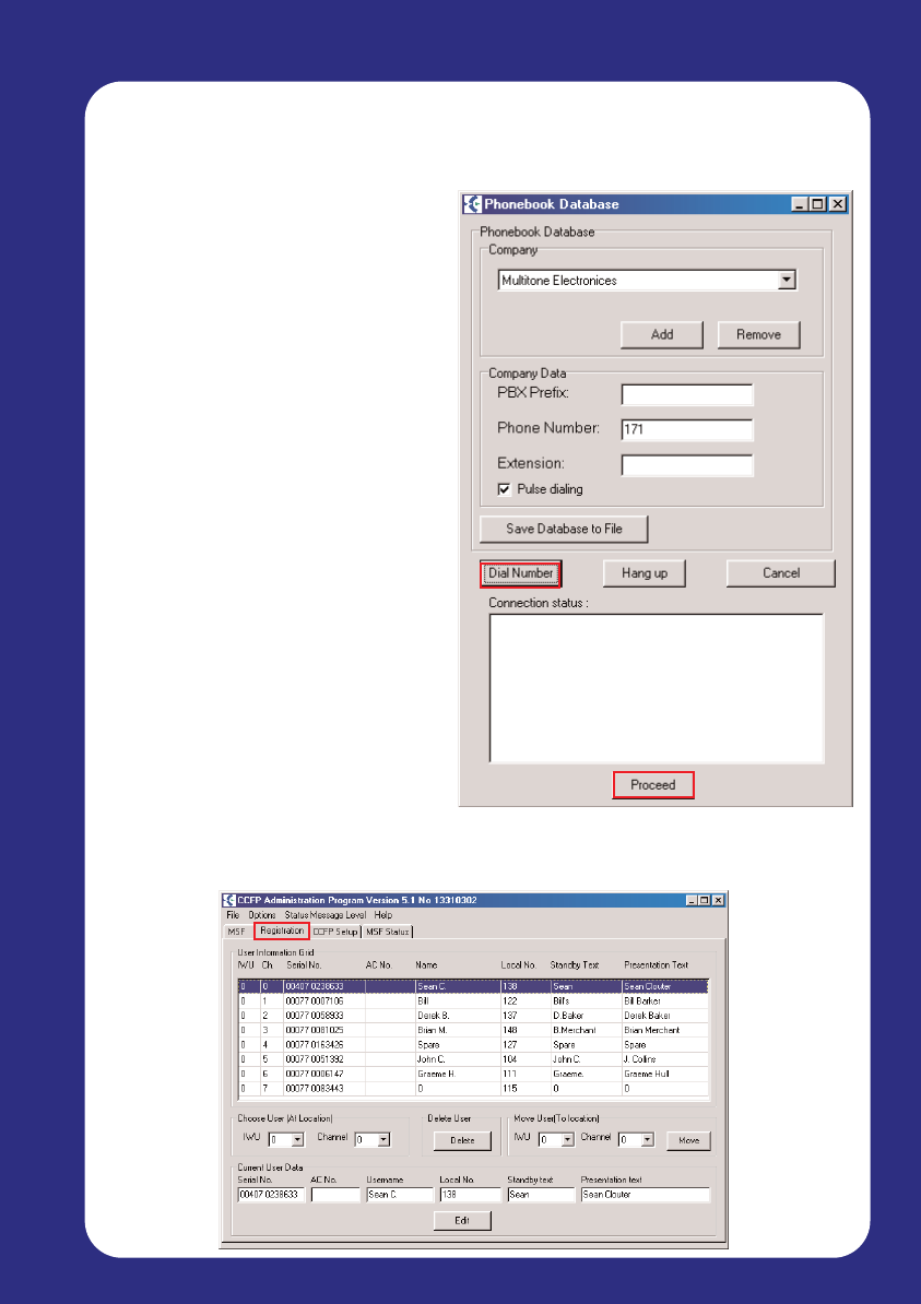
Phone Book
If you select Modem Connection,
you have the option of setting up a
Phone book. This is particularly
useful if you administer several
CS100 Base Stations.
The Phone Book will store the
name and connection settings of
each system you enter, allowing
you to quickly select which system
to enter via a drop-down menu.
The Phone Book also controls the
dial-up connection to the CS100
Base Station. Once connected, the
CCFP Administration Program will
work the same as it would via a
Direct Connection.
When you have entered the
connection details, click ‘Dial
Number’. When a connection is
indicated in the ‘Connection Status’
box, click ‘Proceed’.
This will complete the connection and bring up the main CCFP administrator
screen.
Connection Status
Page 32
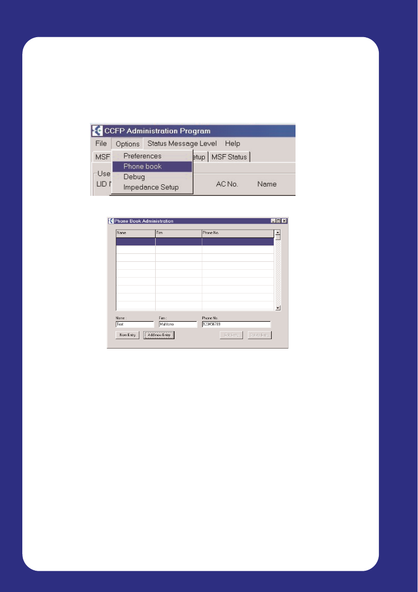
Editing the Phone Book
Within the CCFP administration program, there is an option under ‘Options /
Phone Book’ for editing the Phonebook in the External Services in the
handset.
From the CCFP main screen select ‘options’ and ‘phonebook’
To add a new entry press the ‘New Entry’ button, or choose the empty line
at the bottom of the list. When all the information has been filled in press the
‘Add Entry’ button.
To alter a existing entry chose the entry in the list, make the changes and
press the ‘Edit’ entry button, if the entry needs to be deleted press the
‘System Overview’ button.
Data entry is limited as follows.
Name - 10 characters including spaces
Firm - 10 characters including spaces
Phone Number - 23 characters including spaces
When the CCFP administration program is closed.
PC Configuration
Page 33
PC Configuration
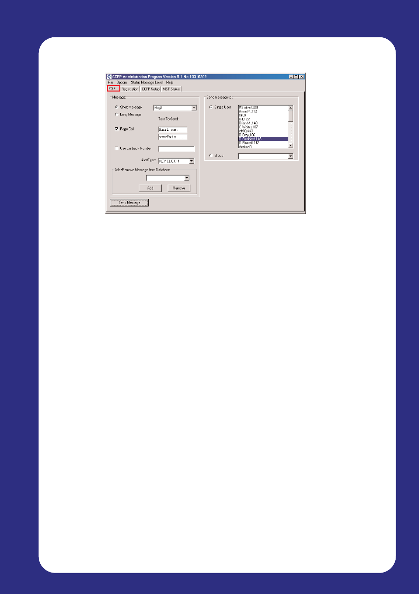
MSF (Message Service Function)
The Message Service Function (MSF) screen is used to send text
messages from the PC to handsets. Messages can be sent to a single user,
or in larger configurations to a group of users.
You can also set the MSF “Alert Type” to alter the way your phone will notify
you of a call so that it is easily distinguishable from other calls.
MSF Screen.
Standard messages may be sent from a user create list by selecting the
message and user/s.
Select “Send Message” to Transmit.
If the “Page Call” box is ticked and a local CS100 extension number
entered the message recipient can call back by going off hook. The number
is dialled automatically.
Alert Type.
The Alert Type may be selected, this allows the receiver of a message to
discriminate on urgency.
Page 34
PC Configuration
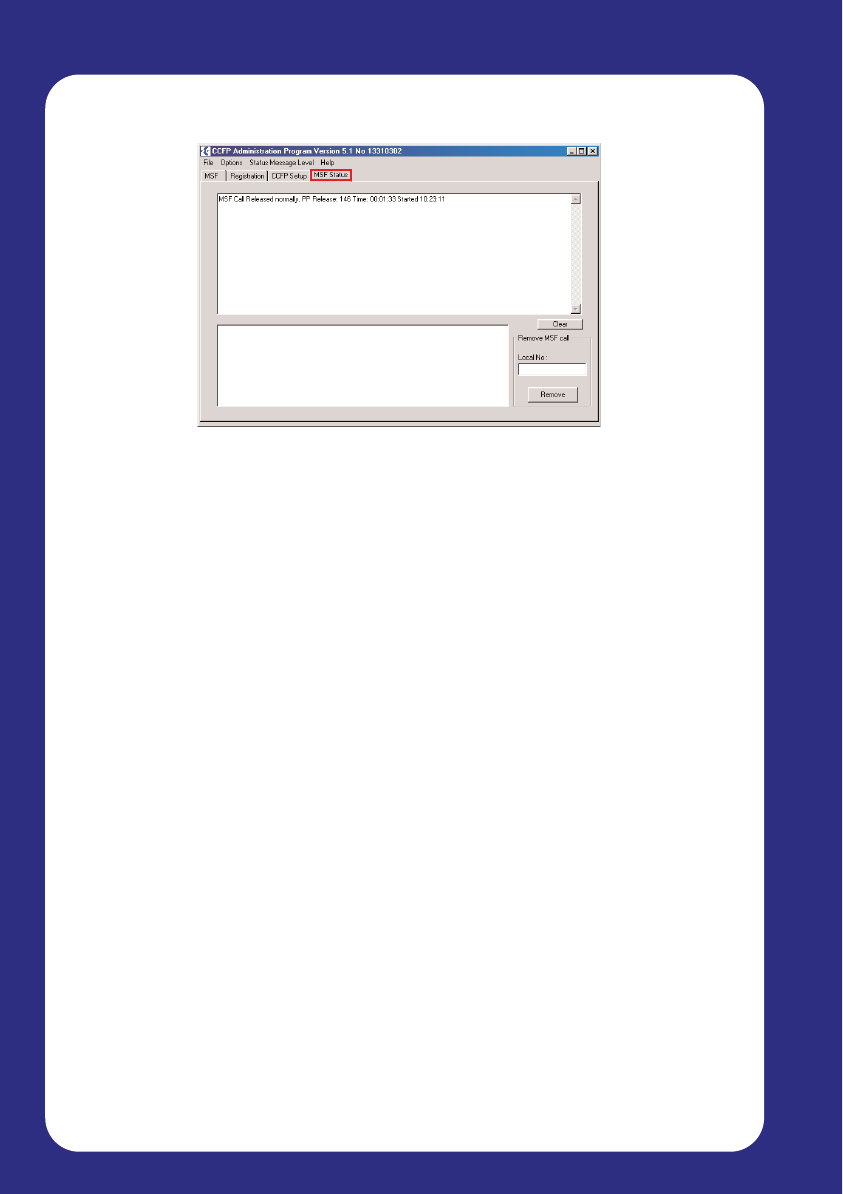
MSF Status
The MSF Status screen displays information on text messages that are in
transit, and that have been received during the current session. The top half
of the window lists messages that have been read by the user, whilst the
bottom half displays messages pending.
Using this information, you can cancel any message that is yet to be read
by a user.
Page 35
PC Configuration
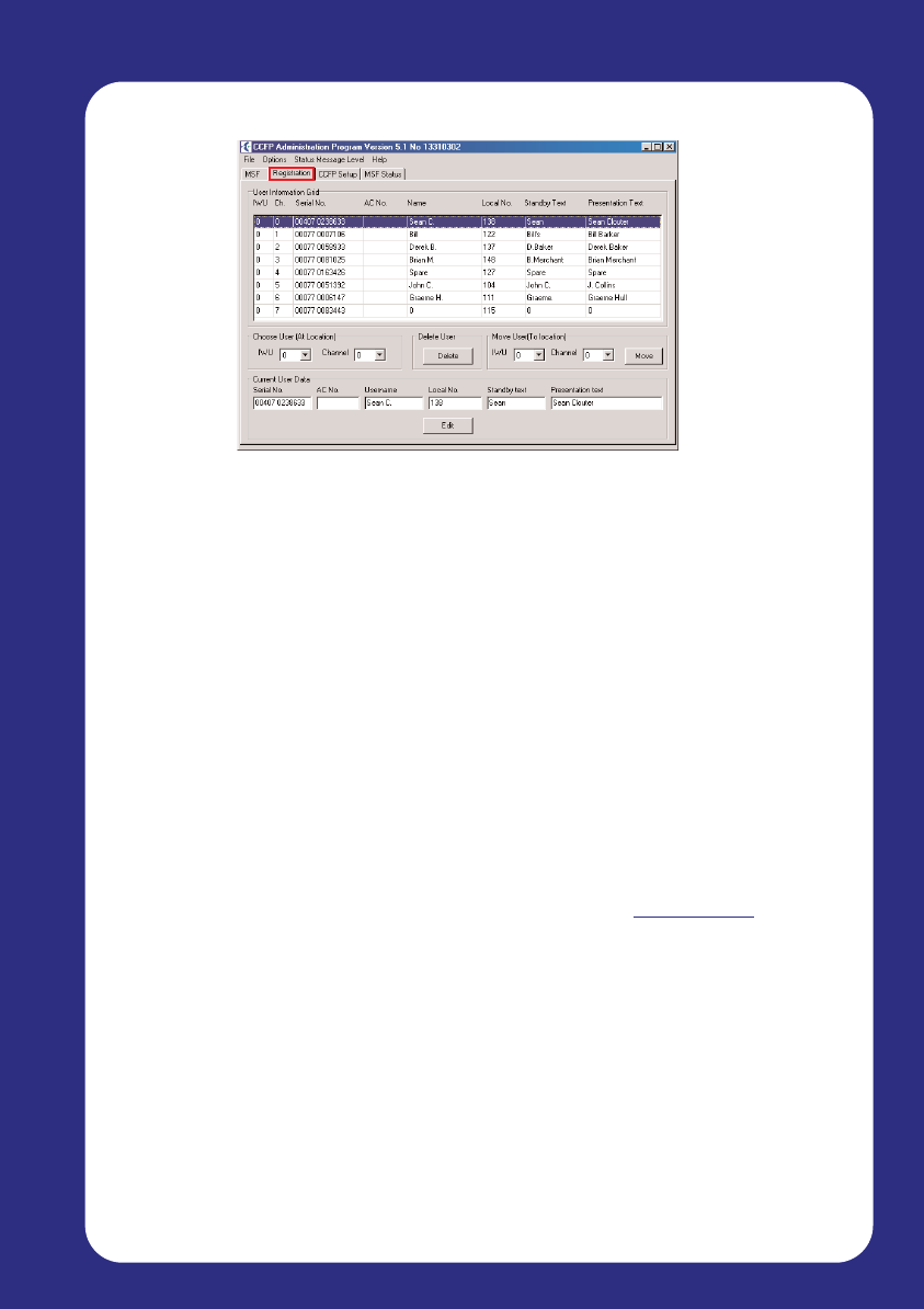
Registration Screen
The Registration screen is used to input configuration details of the handset
and the user. The first handset you register – even if it isn’t channel 00 - will
become the Master handset, giving it local administrative functionality.
As well as registering users and handsets, you can also move or delete
users.
1. Enter user data in the bottom row of entry boxes.
$ Handset serial number must have a space between 00077-xxx
$ A/C number (none by default)
$ User name maximum of 10 characters
$ Local user number - maximum of 12 characters
$ Stand by text (Name, Extension, Job name) maximum 24
Characters
$ Presentation text.(this is information sent to another handset
when called (Name, Extension, Job name), maximum 32
characters - 3 lines of 12-12-10 characters no text wrap.
2. Select ‘Create’ to load the Data.
3. To register handsets
$ Options
$ Preferences
$ Tick the box ‘Allow Subscription’.
4. Register each handset.
Handset data may be edited by selecting the user and ‘edit’.
Select ‘edit’ to confirm the changes made.
Page 36
PC Administration
Handset Registration
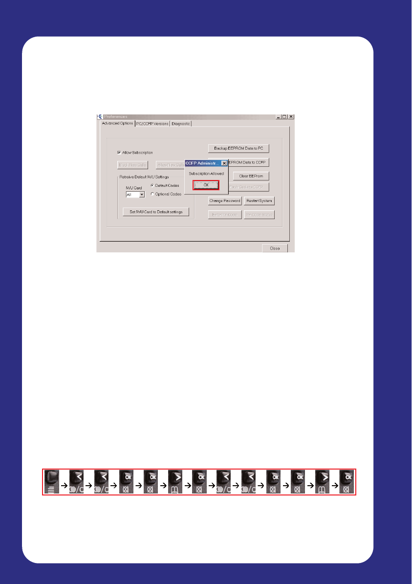
To register the handsets on to the CS100 , registration must be ‘allowed’.
1. Select options-preferences
2. Select ‘allow subscription’ and ‘ok’ then ‘close’
Handsets may now be registered.
1. Menu.
2. Left arrow twice
3. Menu Login - OK
4. Menu Select Login - OK
5. Select Login System 1 - 4 on handset PIE up to 4I
If the ‘Login’ slot has been used the ARI number of the system will be
displayed, you can check the s/w version by *99982* OK.
CH70 PIE 4K or Later. Go to step 7 if this is the first time the handset
has been registered.
6. Select - OK. The Handset will beep.
7. Left arrow twice to ‘subscription create’ - OK
8. Select - OK. and ‘Create system 1 - 4’. AC____ will be displayed, use
arrow keys to select the same registration slot as the login.
(Login 1 = System AC1).
9. Press - OK to register the handset after a short period of time the
handset should beep once. If the handset beeps several times and the
message “subscription failed” is displayed go back to the start of the
handset registration and begin again.
Registration failure checks:
$ Registration Not enabled
$ Wrong slot selected (AC1 = Login1)
$ Handset ID incorrect or not entered into system.
$ AC Number required.
Page 37
PC Administration
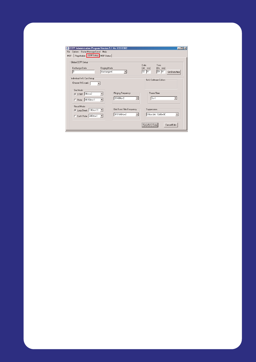
CCFP Setup
The CCFP Setup screen is used for configuring IWU parameters to match
the parameters of the connected PABX.
CCFP Setup should only be reconfigured by users who have attended
a Multitone CS100 Administration training course. Please contact your
distributor for details.
Page 38
PC Administration
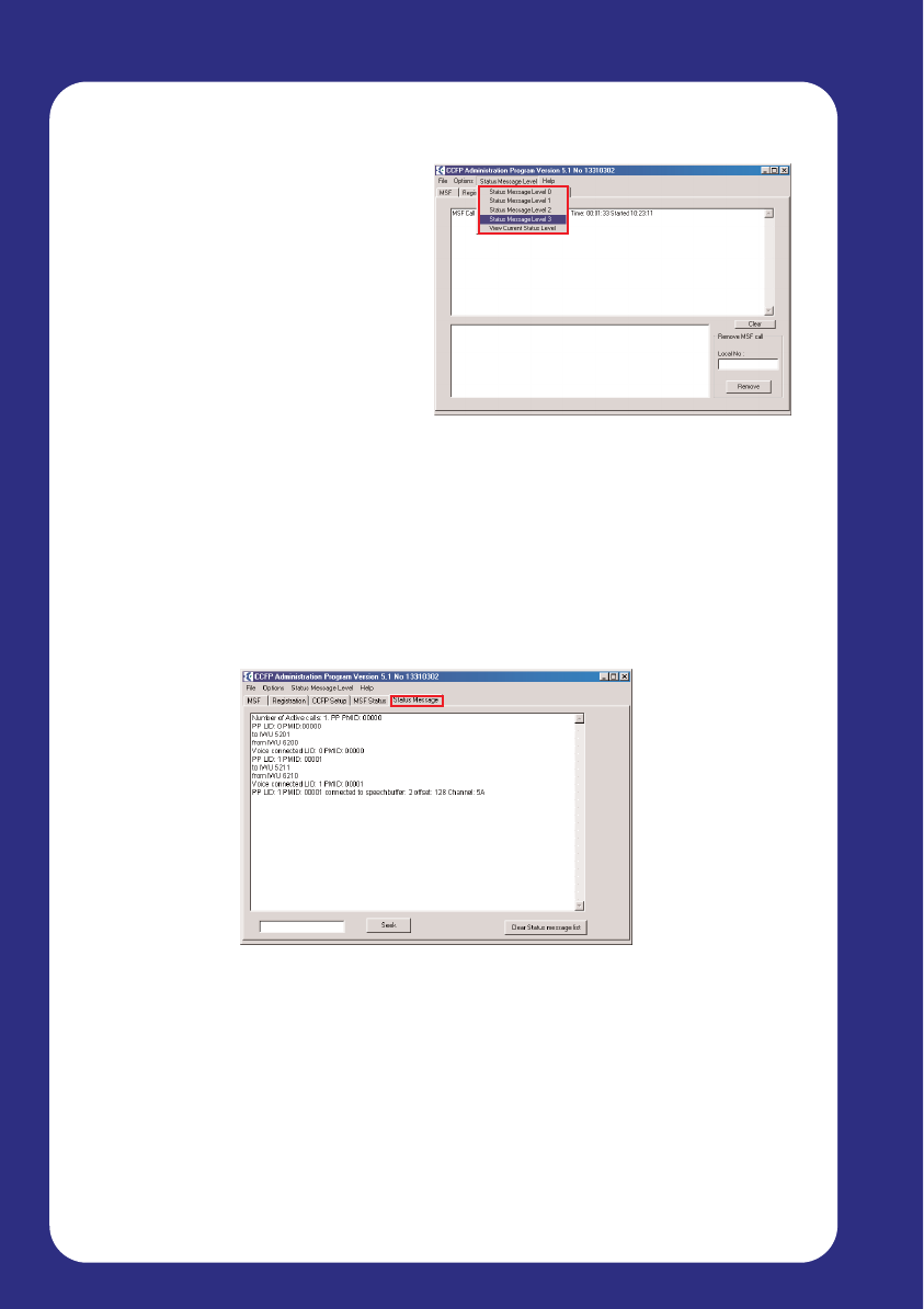
Status Message Level
Using the CCFP Administration
Program, you can track handset
status and call information. This can
be useful for system testing and
verification.
This information is optional, and you
can configure how much information
is displayed via the Status Message
Level button in the top menu.
Level 0: No Status Messages are returned
Level 1: Subscription Request is shown
Level 2: Subscription Request and HS (handset) Connection is shown
Level 3: Subscription Request , HS Connection and RFP / IWU Status is shown
When you set this option to level 1 – 3, the Status Message tab appears in
the CCFP Program. (Note – this option will not appear if you set Status
Message Level to 0).
The Status Message screen provides an overview of the activities that are
currently being performed by the CS100 System.
Using the ‘Seek’ function, you can search for specific types of events.
When the CCFP Administration Program is closed the status level is set to
Level 0 automatically. This is done to prevent to many messages “flooding”
the CCFP. If the status messages are needed you have to set the
[Write Status Level] manually. In order to optimise data-transfer from the
CCFP to the PC and vice versa this setting should optimally be set to zero.
Page 39
PC Administration
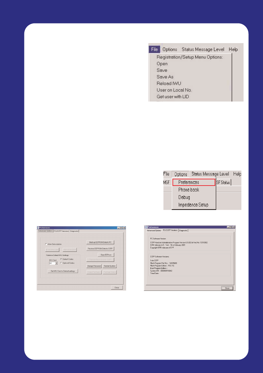
Menu: File
Open: A previously saved configuration
can be restored onto the CS100 System
Save / Save As: Existing User and IWU
configurations can be saved and backed
up
Exit: Exits the program
Note: Opening a new file – even if it is the same file as is already
loaded onto the system – will de-subscribe all handsets. This will also
reconfigure a new Master handset.
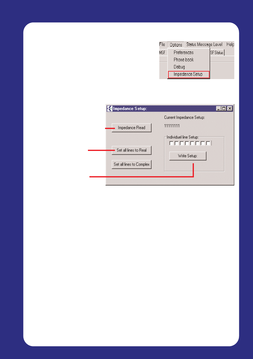
Menu: Options
The Options Menu contains commands for viewing system information,
backup/restore of CCFP data and commands
for debug purposes.
Preferences
The Preferences option contains advanced
settings and configuration information.
Advanced Options:
Allow Subscription
IWU Card settings
Clear / Restart the system
Enter or change password
PC/CCFP Versions:
ARI (Serial) Information
Flash Program part number
Flash Program edition
Page 40
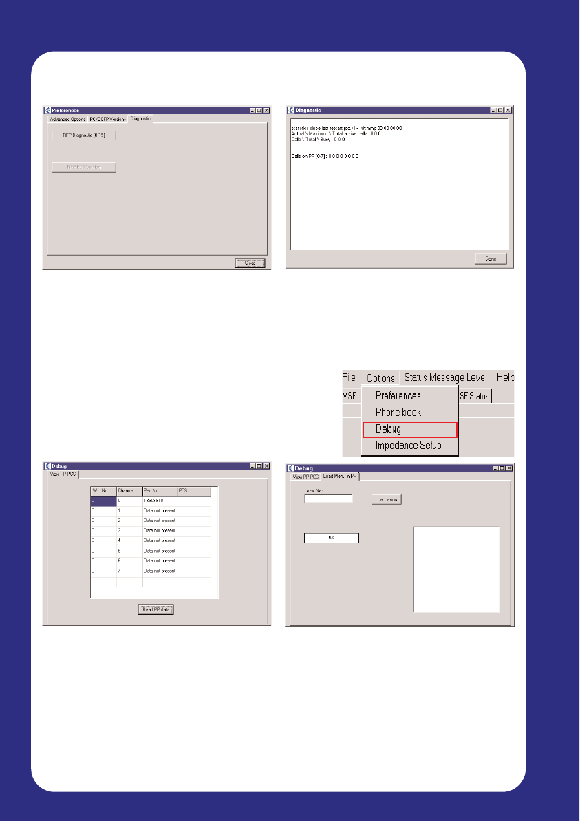
PC Administration
Diagnostic:
Select between available
diagnostic modes
Debug:
View PP PCS
The Debug screen lists the following
information about each handset
connected to the system:
IWU Number
Channel used
Handset Part Number
PCS
Number of calls performed
Number of ‘Busy’ situations
Number of calls per handset
Load Menu in PP
It is possible to load (FLASH) menus
in the PP through the air.
Please consult with your vendor
before considering this!
The Debug screen gives an overview of
the type of handsets connected to the
CS100 System. The type of handset is
displayed as a Part Number.
Technical Appendix
The Technical section should only be used by trained personnel
RFP Diagnostic shows the current system status
Page 41
PC Administration
Impedance Setup
The line impedance to the PABX is adjusted
using the Impedance Setup option.
The default line impedance settings is Complex
(Low).
Click to view current status
Additional setting –
Real (High 600ohm)
Each channel can be
adjusted separately
Technical Appendix

Page 42
5. Repeater and Handset Programming
Software for programming repeaters and handsets can be downloaded from
www.multitone.com . The following features can be programmed.
5.1 Startup text
5.2 Instructions for Installation and Configuration of a Repeater
5.3 Setting up Repeaters
5.4 Determining Where to Locate a Repeater
5.5 Registering a Repeater
5.6 Establishing Repeater Jumps
5.1
Start-up text
Programming the handset start up text requires the Kirktool software and a
CH70-DS Docking station.
The Start-up text can be written in 3 lines of the display. As soon as the box
3040 PP is marked, the option of writing the text in 3 lines will appear.
The current version of software revision 4.6 has a number of features.
$ Volume adjustment for PPI Handset - DO NOT USE.
$ Start up text - used to enter start up text on CH70 Handsets.
$ Repeater - used to program repeaters on CS600 and CS100.
$ Communications - used to set the com port for programming.
$ Download - used for loading alternative languages.
$ Gain Control - used for setting handset volume.
Repeaters

Page 43
Repeaters
5.2 Instructions for installation and configuration of
a Multitone Repeater
Repeater Installation
The following tools and software are required for the programming of
repeaters on the CS100
Drill, Drill Bits, Rawlplugs and Screws
Repeater Programming Kit - Part No. CS600 - PRG - Kit
This includes a programming cable and special two way adaptor.
Software must be downloaded from the Multitone web-site
www.multitone.com
Mounting the repeater
Location
The repeater must be located within 3 metres of an ac mains outlet
socket. The socket should be marked “DO NOT TURN OFF”
Power
The repeater must be located away from any structure or object that could
reduce or obstruct the radio transmissions. It is critical that the repeater is
tested in its preferred location before final fixing takes place.
Final Fixing
1. Pull the wire from the power supply, through the wall holder and then
mount the wall holder on the wall.
2. Connect the wire to the plug on the back of the WRFP and ‘click’ the
WRFP onto the wall holder.
If you need to remove the repeater, please separate it from the wall holder
with a gentle push of a screwdriver.
For further information and technical support please contact Multitone
Electronics website www.multitone.com

Page 44
Repeaters
Programming the CS100 Repeater
We recommend you use the following instructions for programming the
repeater.
Identify the preferred location for the repeater by measuring the
received signal strength walking away from the base station using the
feature code*99981*. The display will show RPN:xx which is the base
station,Q52:64 which is the radio data and RSSI:xx which is the signal
strength.
We recommend that a call is set up between two handsets and
that one person walks away from the base station observing the display
and continuing a conversation. Move to the location where the repeater is
required checking that the Q52 reading remains at 64 and that the speech
quality remains good. If at any time either of these factors change, you
have reached the maximum recommended distance from the base station
to where the repeater may be located.
Repeat this process for any additional repeaters, ensuring that the test
handset is using the base station or the repeater for its communications.
This is critical if repeaters are to be placed in a chain as the signal
measurement and speech quality MUST be checked from the repeater.
Section 5.3 provides detail instructions.
Handset feature codes
*99981* OK Signal strength
*99982* OK Software version
*99985* OK Battery status
*99989* OK 4 Channel coverage test
Page 19
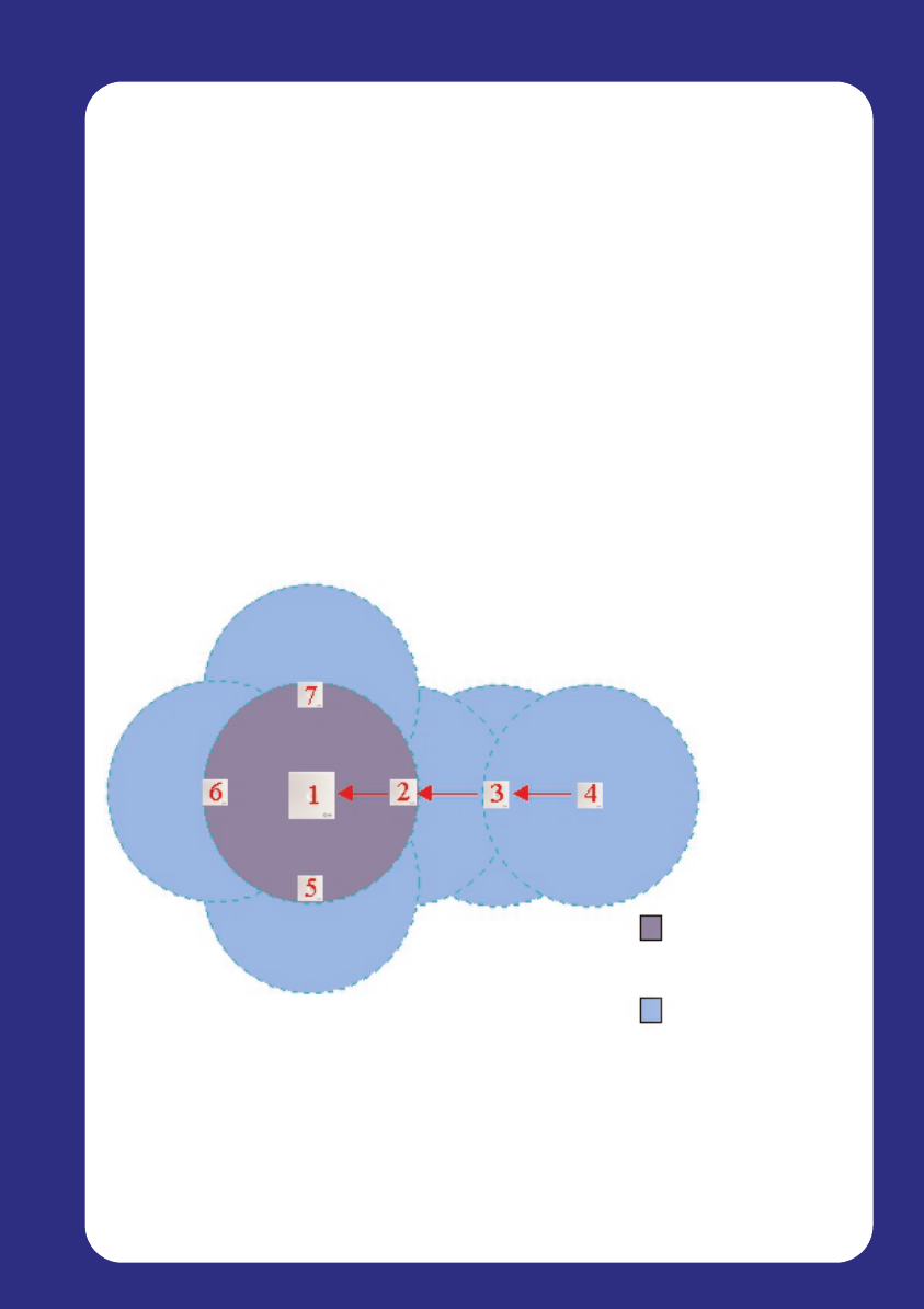
5.3 Setting up Repeaters
For the moment, it is recommended that you skip this section until the
Master Handset has been registered. You can then use that handset to test
the coverage and range of the CS100 Base Station, and use the results to
determine where your Repeaters should be located.
If you have weak spots within your office or work place, you can set up a
series of Repeaters to extend the coverage. It is important to place these
Repeaters in their optimum position so that the coverage area is increased
as much as possible.
For information on testing the coverage and signal strength, see section 5
‘Powering up and Testing’. Once you have determined where your weak
areas are, set up the Repeater and configure it using the instructions found
in Chapter 5. Finally, test the area again and ensure coverage is now
sufficient.
Repeaters can only be set up using a PC – NOT through the Master
handset.
BaseStation coverage area
Area covered by Repeaters
Equipment Installation

Page 46
Text Here
5.4 Determining where to locate a Repeater
Because of the unlimited variations in working environments, determining
where to place a Repeater can never be exact. Signal strength depends on
many outside influences, and so the best method of finding your ideal
location for a Repeater is by using the signal coverage test.
Once the CS100 Base Station is operational, and the handsets have been
registered, use the signal coverage test to find where your weak areas are.
Set up a handset in Field Test mode (*99981* and then enter) and slowly
walk away from the Base Station, keeping an eye on the Q52 readout.
As you get further away from the Base Station, this number will decrease in
value. When the Q52 readout falls below 60, mark the area as a weak spot.
Once you have marked out all the potential weak spots within the area you
need to cover, you can then decide the best location of a Repeater to gain
maximum range.
A voice call between two handsets is strongly recommended to ensure that
the call quality is constant. In some environments it is possible for the
Q52=64 but for speech quality to be poor.
5.5 Kirktool Software Installation
If you have added any repeaters to your configuration to extend the area of
coverage, you will need to register these using a PC before they can handle
call coverage. The software is supplied when you purchase an additional
Repeater, and is called Kirktool.
This can be downloaded from the Multitone website.This software is
frequently updated and may not be the same as shown in this guide.
The latest Version of this software is rev4.5
To install Kirktool, follow these steps, insert the Disk and double click the
icon labelled ‘setup.exe’. Then follow these steps:
1. Click Next to begin the
installation
3. Enter the path for the installation
files to be installed to, and then
click Next
2. Enter your name and company
details, and click Next
4. Click Next to create a new
shortcut in your Start menu
Page 47
Repeaters
Page 48
Repeaters
5. Verify your installation settings,
and click Next to begin copying
files
6. Installation is now complete –
click Finish
Communicating with the Kirktool Software
Before you begin, ensure the Repeater is connected to the computer, and
that the power is connected.
When the Kirktool software has been installed to the computer, you can load
it from your Start menu by clicking:
Start
Programs
Kirktool
Kirktool
Page 49
Repeaters
By default, the Repeater will not be detected by the Kirktool software,
indicated by ‘Nothing Connected’ in the Status Message box. To allow the
software to detect the Repeater, you need to set the communication
method in the ‘Communication’ tab at the top.
Select the COM port you have attached the Repeater to (Usually COM1 or
COM2) and then click ‘Set Comport’. The Status Box should now indicate
that the Repeater is connected, and you are ready to configure the
Repeater.
Page 50
Repeaters
5.6 Registering a Repeater
Select the Repeater tab to the left of Communications, and click the
‘Residential Base’ button to switch to CS100 mode. The following screen
will be displayed:
Read from Repeater Reads the current configuration settings directly
from the Repeater
Write to Repeater Writes the configuration settings you have entered
to the repeater. Your settings will automatically be
checked to make sure they are valid
New Clears all configuration settings in the software
CCFP repeater base Switches mode between Residential and CCFP
Repeater mode - Select Residential (CS100)
Residential base The residential base number (from the label on the
(DECT-z 500) rear side of the Base, for example 000046400266).
(CS100) The initial 4 zero’s are not required in the number,
so you can simply enter 46400266
Base to synchronise The number of the residential base, which the
on repeater must synchronise on. The number must be
between 01 and 07

Page 51
Repeaters
Repeater number This is the number to assign to the repeater. The
assigned number of the repeater must be between
02 and 07
Example:
CS100 Base Station 0000(46423641)
Base to synchronise on 01
Repeater Number 02
When the Base station number, Synchronisation numbers and Repeater
number are entered “Write to repeater”.
The entry box background will change from yellow to white
To check the data has been written to the repeater.
Select “New” to clear data
Select “Read from Repeater”to check that it has been written correctly
Disconnect the programming cable from the repeater and wait at least 20
seconds before plugging in the power lead.
Check the repeater is on line
Red LED is flashing.
*99981* OK - Base Stations are shown - RPN - 01, 02
Press and hold <to clear the screen.
Page 52
Questions
5.7 Establishing Repeater jumps
If you have a particularly large area you need to cover that extends beyond
the range of the CS100 System AND 1 Repeater, you can create a signal
‘Chain’ by adding an extra repeater. For example:
An extended ‘Repeater Chain’ allows for coverage far beyond the
range of a single CS100 System, ensuring whatever the layout of
your facilities space, the CS100 System can adapt to suit your needs.
To configure a Repeater Chain, use the Kirktool software to synchronise the
repeater to an existing Repeater base number.
Page 53
Questions
6.0 Frequently Asked Questions
What is DECT?
DECT is the acronym used for Digitally Enhanced Cordless Telephony or
Telecommunications a global open specification offering speech quality equal to that
found on a fixed line. Conversations are fully secure thanks to the speech channel
encryption.
During the registration process, why does the Master handset detect
more than one ID number?
This will happen when the handset detects another DECT system within its
transmission range which is in subscription mode. Subscription will only be allowed
to the CS100 system whose ID number is on the base of the unit. This does not
breach any safety or security issues.
If I have added Repeaters to my configuration, can I also add more
handsets?
The function of a Repeater is to extend the area of coverage for your existing
handsets. If does not add to the capacity of the existing configuration (i.e. more
channels).
I have recently installed a Repeater in my facility, but I cannot register
it with the CS100 System.
When you register a Repeater to the system, it must be situated within the coverage
area of the CS100 Base Station.
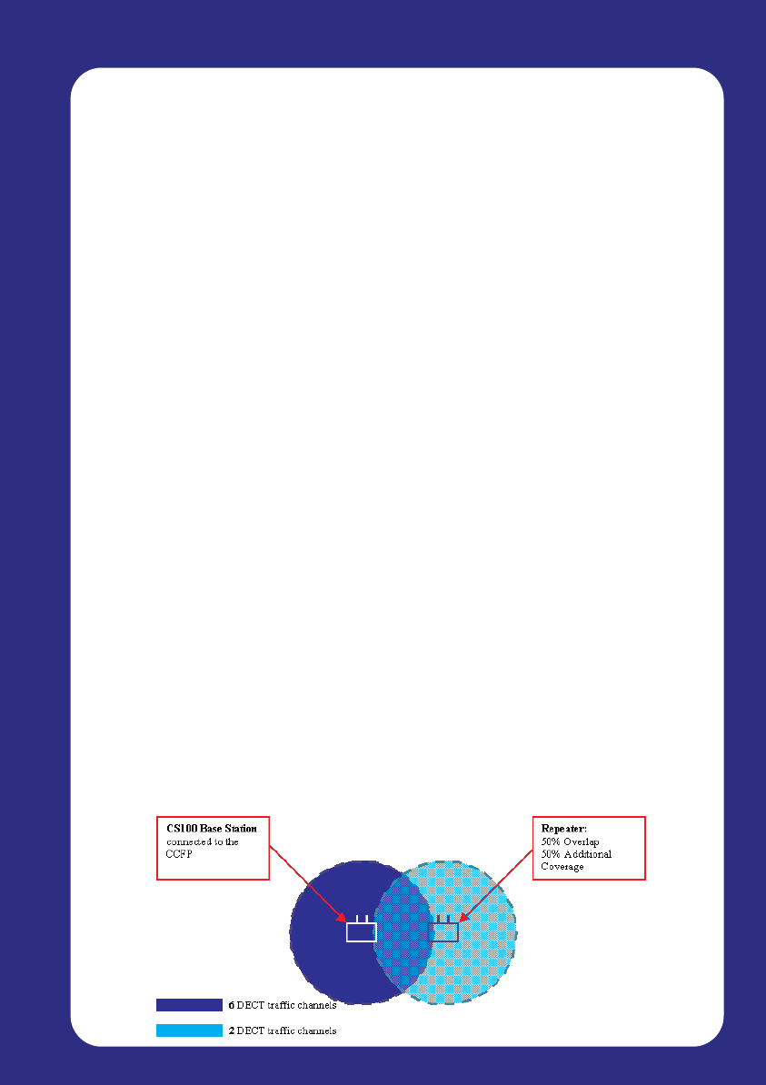
Why can fewer people make or receive calls in the coverage area of a
Repeater or Repeater Chain than within the coverage area of the
CS100 Base Station?
A Repeater is not designed to increase the capacity of the coverage area, meaning
that the CS100 System including Repeaters still has a maximum of 6 simultaneous
traffic channels. However, only the CS100 Base Station itself can provide service to
all these channels within its range. A Repeater ‘borrows’ 2 channels for its extended
coverage area, meaning that if you are only within range of the Repeater and not the
CS100 Base Station, you will only have access to the 2 traffic channels as illustrated
below:

Page 54
Questions
Can the CS100 system be connected to a public or private network?
This equipment is NOT intended to connect to a public or private network. It is only
intended for closed connection to TNV2 circuits. This is a line supplied by a PBX
and not exposed to over voltage such as may be induced on a PSTN line.
What happens when all 6 speech channels are in use?
Each handset uses 1 channel when making a call – either internally or externally.
When 6 handsets are engaged in a call, the system sends out a busy signal. On the
Multitone CH70 handset this is indicated by a flashing antenna icon, displayed in the
bottom left of the screen.
Will my call get dropped if I walk to an area that is covered by a
Repeater that is already in full use?
No. If during a telephone conversation you move to an area where coverage is not
attainable, either because the system is full (all the lines are in use) or because you
are simply coming to the end of the broadcast range, you will hear a Signal Warning
beep. This ensures that you do not lose a call whilst on the move.
Why do Multitone not support the use of 3rd party handsets?
Multitone is continually striving to give our customers cordless systems that are both
reliable and cost effective. We are constantly evaluating new handsets as they come
on the market as we are conscious that there are a lot of low cost ‘Home base’
products available which have a lower price than system handsets.
These handsets are designed for use with a single home base station with no
requirement for handover, in some handsets the handover functionality in the
embedded software has not been written, as it is not required. These units are
produced in volume where the overriding factor in the design and build process is
cost. In their own environment, ‘the home’ or small office, they work exceedingly well
and are extremely good value for money.
However when used on a multi-cell system such as would be installed on a larger
site requiring a number of base stations this lack of ‘handover’ functionality causes
problems not only with the handset concerned but also with the system itself. After
exhaustive tests at some of our sites using these low cost handsets it was
discovered that these handsets generate a high overhead of radio traffic because of
the number of additional radio cells that they can see in the Over Air Interface (OAI).
This causes an inefficient use of the OAI and causes lost or dropped calls resulting
in a poor system performance.
Multitone do not recommend nor support these low cost handsets and will therefore
charge a supplement on existing contracts or callouts on sites which are found to be
using these ‘Home’ products.

Page 55
CS100 Messaging
7.0 CS100 Messaging - P318 & Access Integrator-K
It is possible to increase even further the usefulness of a cordless
environment by integrating fire alarms, burglar alarms, nurse call systems,
messaging software, paging systems and simple switches (such as pressure
pads, door bells etc.) with the CS100.
This can be achieved with the addition of Multitone Electronics' P318 or
Access Integrator-K messaging interface.
The P318 has serial ports that can be configured to take direct data from
TAP, ESPA and a range of other protocols. It also has 32 Voltage free
contacts which can be configured as normally open or closed. The P318 will
also allow the CH70 handset to activate these switches remotely by entering
a code.
Activation of contacts can be programmed to send a message to a handset
or team of handsets.
Examples of uses for Voltage free contacts:
Notify users of door bell push
Alert users to the customer presence via a pressure pad.
Pump or refrigeration alarms
Switch lights on or off via the handset
Panic buttons.
Access Integrator provides 16 Voltage free contacts connected to a LAN and
has an Internet browser interface for easy to use system administration.
Any PC with user rights can send messages to a single handset or team of
users, Access Integrator-K has two serial ports, one for connection to a
Multitone CS100 or CS600 (Kirk system 1500 or 500) and a second serial
port for TAP, MEP or ESPA input.
For further information visit the multitone web site www.multitone.com
or contact your account manager.

Page 56
This Page is intentionally blank

Page 57
Technical Specs
8.0 Technical Specifications
8.1 CS100 System features for all 8 DECT lines
DTMF transmit: All 16 (0-9, A, B, C, D, *, #)
Duration 80, 90, 100 ms
DTMF receive: All 16 (0-9, A, B, C, D, *, #)
1.5% + 5Hz
Dynamic –4 - -28dB
Tone duration > 50ms (option)
Pause duration > 40ms
Twist < 6dB
Single tone receive: 300 – 2000 Hz
Single tone send: Pulse send:
300 – 4000 Hz (option)
Frequency (10 Hz) make/break:40ms/60ms
or 34ms/66ms
Ringing receiver: Duration > 200ms
20 – 120V
13Hz – 60Hz
Echo cancelling: Overall echo reduction – 34dB
Canceller: > 24 dB
Suppressor: 12 dB
Loop break: 100ms / 290ms / 630ms

Page 58
Technical Specs
8.2 IWU Setup for CCFP Administration Program
Recall mode Dial mode
Loop Break DTMF
Pulse
Recall timing DTMF timing active = pause
Loop Break: 70ms 70ms 150ms
100ms 80ms 200ms
290ms 90ms 250ms
630ms 100ms 2500ms
Pulse timing 10Hz Dial tone detect pause
Make / break: 40ms / 60ms 1 sec 4 sec
34ms / 66ms 2 sec 6 sec
3 sec 8 sec
Ring freq. Dial tone filter
13 – 60Hz 315 – 545Hz
20 – 60Hz 385 – 465Hz
20 – 30Hz 345 – 505Hz
265 – 600Hz
Suppressor
Office
Light noise
Heavy noise All have the option of either 9 or 12dB
Extreme noise
OFF
