Multitone Electronics PLC IP133 Multitone I-Page – IP133 User Manual Multitone I PAGE
Multitone Electronics PLC Multitone I-Page – IP133 Multitone I PAGE
Contents
- 1. manual
- 2. Manual installation guide
manual
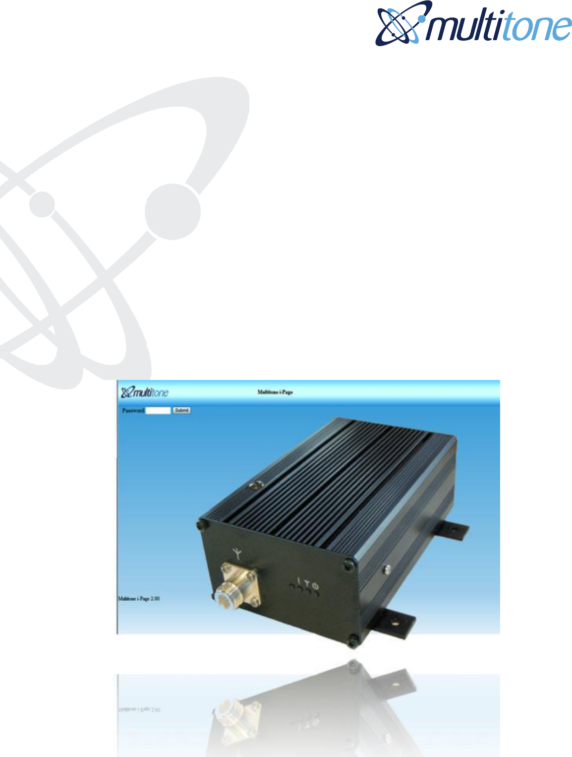
Multitone i-Page
User and
Installation Guide
ISSUE CONTROL
Issue
Date
Remarks
01
01.08.11
First Issue
02
25.10.11
Grammatical changes, removal of some pager images and
addition of waterproof pager

i-Page USER AND INSTALLATION GUIDE
Index of contents
Important User Information
Section Description Page
1.0 Checking supplied equipment 2
2.0 Tools 2
3.0 Equipment required 2
4.0 Assembly requirements 3
4.1 Assembly 3
4.2 Mounting 3
4.3 Power supply 3
4.4 Network cable 4
4.5 Aerial fitting 4
5.0 i-Page setup 4
5.1 i-Page network setup – Changing IP address for use on local network 5
5.2 IP Settings - Set static IP address, Netmask, gateway, Syslog for i-Page 5
5.3 Language - Select browser and pager languages 6
5.4 Clock - Set time and date 6
5.5 Paging setup - Set system address, paging format, time on/off, message 7
length and coverage test
5.6 Password - Set one administrator or five user passwords 7
5.7 Users - Add, amend or delete users 7
5.8 Groups - Add and remove groups 8
5.9 Stored Messages - Add or remove stored messages up to 80 characters 8
5.10 DLC’s - Programme DLC alarm details 9
5.11 Serial port - Select serial port protocol 9
5.12 Backup/Restore - Backup and restore i-Page data 10
5.13 Factory reset - Reset i-Page to factory setting. Note that all system data is 10
destroyed
6.0 Engineering button – Temporarily restore default IP address 10
7.0 Paging users and groups - User interface for paging users and groups 11
7.1 Logout - Used to log out of Multitone i-Page 11
8.0 Syslog message tracking – Optional software form logging messages 11
9.0 Transmitter alignment – Changing the transmitter frequency 11
10.0 Software upgrades – Updating i-Page 12
Appendices
Appendix 1 DLC alarm and serial port technical requirements 14
Appendix 2 Frequently asked questions and fault finding 15
Appendix 3 i-Page specifications 16
Appendix 4 Multitone Pagers 17
Appendix 5 i-Page Spares 18

IMPORTANT USER INFORMATION
CAUTION
THIS PRODUCT HAS NO REPLACEABLE COMPONENTS. ALL FAULTY UNITS SHOULD
BE RETURNED TO MULTITONE OR THEIR AGENT, FOR REPAIR. FOR AVAILABLE
SPARE PARTS, SEE APPENDIX 6.
STATIC SENSITIVE DEVICES ARE USED WITHIN THIS EQUIPMENT. OBSERVE STATIC
SAFETY PRECAUTIONS IF CHANGING COMPONENTS.
ENSURE THE UNIT IS MOUNTED IN A DRY ENVIRONMENT, BUT NOT OVER A HEAT
SOURCE OR IN DIRECT SUNLIGHT.
WEEE DIRECTIVE & PRODUCT DISPOSAL
At the end of its serviceable life, this product should not be treated
as household or general waste. It should be handed over to the
applicable collection point for the recycling of electrical and
electronic equipment, or returned to Multitone or their agent, for
disposal.
Company Liability
The information in this manual has been carefully compiled and checked for technical
accuracy. Multitone Electronics plc accepts no liability for inaccuracies or errors. In line with
the company policy of technical advancement, the information within this document may be
changed. The user should ensure that the correct issue of the document is used. Comments
or correspondence regarding this manual should be addressed to:
Safety Summary
Important Safety Information
The Multitone i-Page IP133 Radio Paging Transcoder equipment, contains a
low power (5 Watts) radio transmitter and is intended for use with either an
externally mounted dipole antenna, or a “local” unity gain (or less) "desk-top"
whip antenna.
The equipment’s performance may be characterized in accordance with the recommended
MPE requirements of the European Council Directive 1999/519/EC on the limitation of
exposure of the general public to electromagnetic fields (0Hz - 300GHz), as given in Annex
III, Table 2; the requirements of FCC 47CFR and Industry Canada Standard RSS102.
Where an installation is to be fitted with a "local" whip style antenna, the following criteria
must be adhered to, in order to reduce and comply with the Electro-magnetic radiation
absorption regulations.
Multitone Electronics plc
Technical Publications
Hansa Road
Hardwick Industrial Estate
Kings Lynn
Norfolk
PE30 4HX
Englan
NOTE: Any equipment and antenna that is installed within an area normally populated
whilst it is in use, must be located in a position where people may not approach, or be
located within 1m of the radiating antenna, for periods in excess of 5 mins. in any 1
hour. This distance is calculated to include an additional safety margin for the
product.
Compliance Information
EU Territories - This product complies with the requirements of the EU Radio &
Telecommunications Terminal Equipment Directive 99/5/EC. A complete copy of the
associated Declaration of Conformity for this and other Multitone products may be found at
the Multitone Internet address www.multitone.com.
This is Class 2 type equipment under the terms of the R & TTE Directive
and is therefore subject to restrictions in its use. Before installation and
use, consult your local radio communications spectrum authority, for
licensing and frequency regulations.
US & Canada - This product has been tested and certified for use in both the US and
Canada. Any modifications to this equipment not expressly authorised by Multitone, could
void the user's authority to operate the equipment.
(The term "IC:" before the certification/registration number, only signifies that the Industry
Canada technical specifications were met.)
Installation Notes
The equipment should be positioned so that there is no interference to the flow of air around
the unit and away from sources of heat. It should only be mounted to a wall, as
recommended in the installation instructions.
Care must be taken during installation to keep the power supply away from
excessive RF fields.
Where the transmitter power is to be greater than 2.5W, the antenna must be sited a
minimum of 1.5 metres away from the IP133 housing and power supply.
In cases where a close-coupled antenna must be used, the transmitter power must be
reduced to a maximum of 2.5W and care must be taken to position the antenna at least
0.5m from the power supply unit.
All installation wiring should be carried out in accordance with recognised Codes of Wiring
Practice, applicable to the equipment and circuits involved, e.g. Mains power, telephone
and/or radio. Power supply cords and other leads should be routed so that they are not likely
to be walked on, or pinched by items placed upon or against them.
WARNING
Do not install / use this equipment near sources of water,
moisture, or in areas where explosive gases may be
present! Do not expose to strong magnetic fields, extreme
temperatures or strong sunlight.
Particular attention should be paid to cord entrance and exit points.
Where installation involves an external radio aerial/antenna, the antenna should be located
away from power lines. Ensure that where applicable the antenna system is grounded, to
provide some protection against voltage surges and the build-up of static charges.
This equipment has been designed to conform to the relevant Radio and EMC performance
standards, but it may be necessary to take additional precautions during installation, to
ensure continued compliance.
Use only cables supplied, or suitably rated power cables and screened signaling cable.
Where quoted, do not exceed specified cable lengths and keep cable runs to a minimum,
especially on the outside of buildings.
Do not unnecessarily route wiring alongside cables from or through areas that are a source
of interference e.g. heavy plant and switch rooms, RF transmitter housings, without taking
suitable precautions to reduce EM interference coupling.
Where necessary, use additional protection e.g. armoured trunking, surge arrestors,
especially on the outside of buildings.
Where any interference problems are observed, it may be required to fit additional filtering
components such as ferrite absorbers, or in-line filters. If such action proves to be necessary,
contact either Multitone or their authorised agents.
Connection of Power Supplies
Use only power sources specified, or supplied by Multitone. The use of another device will
invalidate any declared conformity for this equipment, if as a result it ceases to conform to
those standards on which conformity is based.
The equipment should only be connected to a power supply as described in the operating
instructions, as marked on the equipment, or supplied by Multitone. Do not overload outlets
and extension cords, as this can result in fire, or electrical shock.
Where equipment has been provided with a three-wire grounding type plug, this plug will only
fit a grounding type power outlet. This is a safety feature and should not be defeated. If you
are unable to use a grounding outlet, contact your electrician.
Where equipment has been has been provided with a polarised line plug (one blade wider
than the other - US/Canada), this plug will only fit a power outlet one way. This is a safety
feature and should not be defeated. If you are unable to insert the plug fully, try reversing the
plug. If the plug still does not fit, contact your electrician to replace the obsolete outlet.
Servicing
This equipment contains non user-serviceable parts. All repairs to be undertaken by qualified
service personnel. In the case of a problem, please contact your service
representative/agent.
All the safety and operating instructions should be read before the equipment is connected
and operated and retained for future reference. All warnings marked on the equipment
should be strictly adhered to. No attempt should be made to remove any designated safety
covers, as these areas contain voltages of a sufficient magnitude to constitute a risk of
electric shock to personnel.

Acknowledgement
i-Page wishes to acknowledge that the TCP/IP stack used in this product is Copyright (c)
2001, 2002 Swedish Institute of Computer Science. All rights reserved.
This file is part of the lwIP TCP/IP stack. Author: Adam Dunkels adam@sics.se.
THIS SOFTWARE IS PROVIDED BY THE AUTHOR ”AS IS'' AND ANY EXPRESS OR
IMPLIED WARRANTIES, INCLUDING, BUT NOT LIMITED TO, THE IMPLIED
WARRANTIES OF MERCHANTABILITY AND FITNESS FOR A PARTICULAR PURPOSE
ARE DISCLAIMED. IN NO EVENT SHALL THE AUTHOR BE LIABLE FOR ANY DIRECT,
INDIRECT, INCIDENTAL, SPECIAL, EXEMPLARY, OR CONSEQUENTIAL DAMAGES
(INCLUDING, BUT NOT LIMITED TO, PROCUREMENT OF SUBSTITUTE GOODS OR
SERVICES; LOSS OF USE, DATA, OR PROFITS; OR BUSINESS INTERRUPTION)
HOWEVER CAUSED AND ON ANY THEORY OF LIABILITY, WHETHER IN CONTRACT,
STRICT LIABILITY,
OR TORT (INCLUDING NEGLIGENCE OR OTHERWISE) ARISING IN ANY WAY OUT OF
THE USE OF THIS SOFTWARE, EVEN IF ADVISED OF THE POSSIBILITY OF SUCH
DAMAGE.

1 i-Page Installation & User Guide 9261-8879 Iss 2
i-Page User & Installation Guide
Product Overview
Multitone i-Page is a small to medium business transcoder and supports a range of Multitone
and OEM pagers. With a synthesised transmitter that can operate at up to 5watts, i-Page
has good radio coverage in the majority of environments.
Multitone i-Page can also be integrated with other Multitone messaging products to provide
messaging management from building and property management systems, fire alarms,
security alarms and other safety, property or security devices.
Output of messaging alarms can also be directed to other mobile DECT, PMR, GSM, WiFi or
personal security devices.
Contact Multitone for further information, or visit our website on www.multitonei-page.com.
2 i-Page Installation & User Guide 9261-8879 Iss 2
1.0 Checking supplied equipment
Unpack and examine the contents against the list given below:
i-Page Transcoder Unit Qty 1 (Fitted with wall mounting plates).
Power supply unit, 3-pin plug (UK), 2-pin (Europe) or 2 pin (US/Canada) Qty 1
Desk top antenna assembly * Qty 1 Part no 5501-0024
o Supplied only when requested on SSF
o Note that any alternative aerial must be an approved product supplied by
Multitone
Set up and assembly guide 9261-8880
2 metre ethernet cable. Item 7718-0022
Your i-Page may have been supplied with either Multitone or OEM pagers
Your pagers are pre-programmed to work with Multitone i-Page on the same radio
frequency, but will not have the pager addresses pre-programmed unless requested
1.1 Pager bundles
Pager bundles may consist of 4, 8 or 12 pagers, pre-programmed on to the radio
frequency you have provided.
o Pagers will be pre-programmed onto the correct paging frequency
o The pager address required must be manually configured
1.2 Multitone pagers
A Multitone pager is pre-programmed and the pager address(RIC) may be viewed
when the pager is turned on. The programmed frequency is noted on the back of the
pager.
2.0 Tools
The following tools may be required:-
Screwdrivers - flat and cross-point
2.5mm Allen key – for removing the wall mount plate
IDC Insertion Tool. Only required when DLC alarm contacts are equipped
o Installation of DLC alarm contact connections should only be carried out by a
qualified service engineer
Drill and bits
o Required if i-Page is to be wall mounted
3.0 Equipment Required
The following equipment may be required:-
PC or laptop, with cable part number 7761-8251 for adjustments to transmitter
o This work should only be carried out by trained personnel
o Damage to transmitters due to incorrect procedures or hardware being used,
will be charged at replacement costs
Multitone i-Page includes a browser and administration programme and is designed
for use with any PC or laptop equipped with an internet browser programme such as
Internet explorer, Firefox etc. connected to the customer network
3 i-Page Installation & User Guide 9261-8879 Iss 2
4.0 Assembly requirements
4.1 Assembly
The installation of alarms and servicing of this product must only be carried out by
qualified personnel.
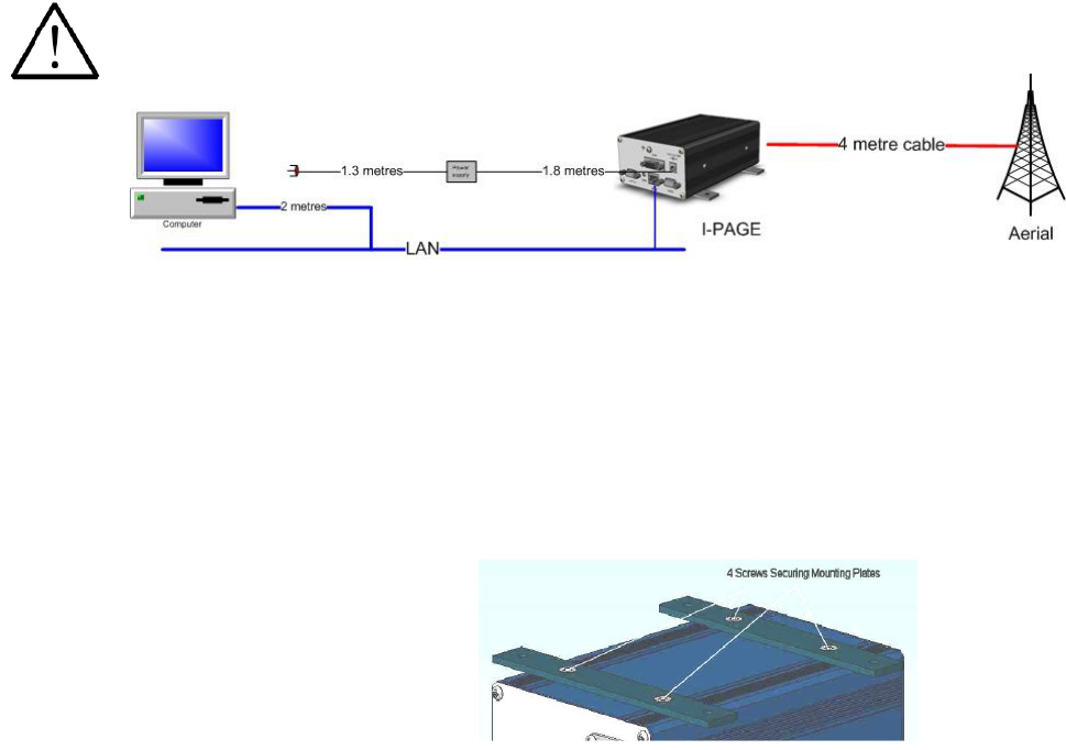
i-Page must be assembled with the following points in mind:-
Transcoder must not be installed next to the power supply or aerial – place these
items as far away from the transcoder as possible, to ensure there is no interference
i-Page requires an IP network connection within 2 metres
A 120/230 volt mains socket must be within 3 metres of i-Page
Computer with a browser such as Internet Explorer, Firefox or other
browser for programming i-Page
The IP133 i-Page can be wall or shelf mounted. i-Page is supplied for wall mounting and has
wall mount plates attached. For desktop mounting remove the wall plates and fix the
enclosed rubber feet.
An earth wire MUST be fitted to the 4mm earth screw terminal on the back of the transmitter
using the earthing lead supplied, or suitable equivalent.
4.2 Mounting
Attach the unit to the wall through the four mounting holes provided, using suitable fixings.
For desk or shelf mounting, remove the four screws using a 2.5mm Allen key and substitute
the four rubber feet supplied. Where this method of installation is used, ensure that the unit
is physically stable once all the leads have been connected.
Desk mounting
The unit must be on a stable surface and the correct distance away from power supply,
aerial or any other radio device.
4.3 Power supply
The power supply can be wall mounted using an optional mounting bracket. This item is an
accessory and may be purchased under part number 1061-8185-1.
The unit may be wall-mounted using the
procedure below.
If i-Page is to be fitted on a wall use the
mounting plates as a template and mark
the drilling points, (note: plugs and
screws are not provided.).
4 i-Page Installation & User Guide 9261-8879 Iss 2
Once the bracket is attached to the wall, fit the power supply to the bracket by feeding the
DC output lead through the square hole in the bracket, from the inside. With the power
supply sitting centrally between the two lugs of the bracket, insert the mains connector into
the power supply through the oval hole, ensuring that it is fully pushed in.
This locks the power supply into the bracket.
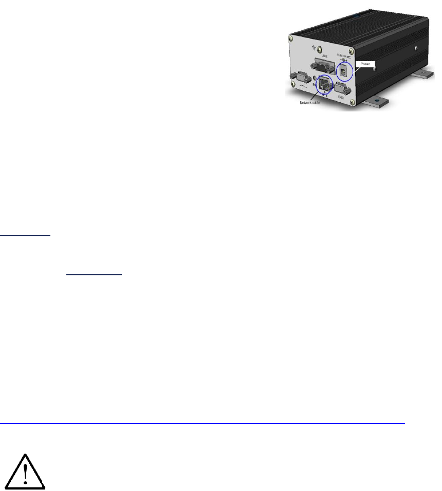
Connect the power supply plug into the i-Page power
socket.
4.4 Network cable
Plug the network cable into a free network point and
the other end into the RJ45 network cable connector.
4.5 Aerial fitting
i-Page is supplied with a desktop aerial, with 4 metres of cable and connector. If an
alternative aerial is fitted, the impedance of the aerial should be 50 ohms.
Care must be taken during installation to keep the power supply away from excessive
RF fields.
Where the transmitter power is to be greater than 2.5W, the antenna must be sited a
minimum of 1.5 metres away from the i-Page housing and power supply.
In cases where a close-coupled antenna must be used, the transmitter power must be
reduced to a maximum of 2.5W and care must be taken to position the antenna at least 0.5
metres from the power supply unit.
Any equipment and antenna that is installed within an area normally populated whilst
it is in use, must be located in a position where people may not approach, or be
located within 1 metre of the radiating antenna, for periods in excess of 5 mins in any
1 hour. This distance is calculated to include an additional safety margin for the
product.
Note: You, (the user), are responsible for obtaining a license to operate your paging system
from Ofcom (UK), or your local radio/spectrum licensing agency.
http://licensing.ofcom.org.uk/binaries/spectrum/business-radio/forms/OfW432.pdf
5. i-Page setup
When i-Page has been assembled according to points 4.1 to 4.5 and the
ethernet cable from i-Page is connected to a network point, you are ready to
programme your system from your computer.
Note: Default IP address is 192.168.1.11 and network mask of 255.255.0.0
i-Page only supports a static / fixed IP address
A network address will need to be allocated by your MIS or IT manager
5 i-Page Installation & User Guide 9261-8879 Iss 2
5.1 i-Page network setup
Changing computer IP address
o (Example using Microsoft XP)
START - MY NETWORK PLACES – VIEW
NETWORK CONNECTIONS – LOCAL AREA
CONNECTION
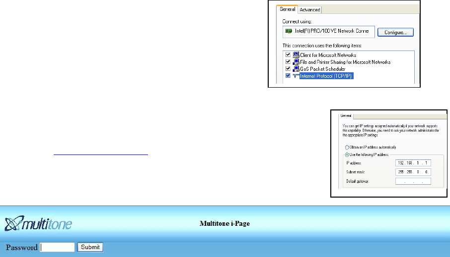
Select PROPERTIES
Select “Use the following IP address”.
Enter, 192.168.1.11 and Netmask 255.255.0.0
Select “OK” and “OK” and the new IP address will be saved
Open your default browser and type;
o http://192.168.1.11/ into the top bar
o You will see the main screen of Multitone i-Page
displayed and can commence programming
There is no default password
Login to i-Page and the menu option below will be displayed
The menu items presented on the left hand side of the screen are used to programme i-
Page and to send messages to users and groups.
Logout - Used to log out of Multitone i-Page
Paging - User and administration interface for programming and paging
Users - Add, amend or delete users
DlC - Programme DLC alarm details
Groups - Add and remove groups
Messages - Add or remove stored messages up to 80 characters
Clock - Set time and date
Password - Set one administrator or five user passwords
Paging setup - Set system address, paging format, time on/off, message length and
coverage test
Language - Select browser and pager languages
IP settings - Set static IP address, Netmask, gateway and Syslog for i-Page
Serial port - Select serial port protocol
Backup/restore- Backup and restore i-Page data
Factory reset - Reset i-Page to factory setting. Note that all previous system data will be
erased!
5.2 Browser IP settings
The majority of businesses have a network managed by an IT or MIS manager and they will
be able to assist with the following instructions and will also need to provide an IP address
for i-Page, unless the default IP address is used.
These settings allow any user or administrator to use i-Page from their internet browser
software (Internet Explorer, Google, Firefox etc.).
Log in to i-Page, PASSWORD - no password required.
6 i-Page Installation & User Guide 9261-8879 Iss 2
Select IP settings from the list. Your i-Page unit may require a new IP address in order that
it may be accessed from your local network. Contact your IT / MIS network manager for
details or assistance.
You must make these changes, in order for you to use you i-Page on your local network.
(Refer to section 5.1.)
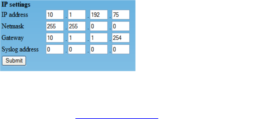
Enter the new IP address and Netmask plus gateway and Syslog IP address.
Example: Obtain the IP address Netmask, gateway and Syslog details from your IT network
manager.
A gateway address is only required if i-Page will be accessed from a different LAN network
e.g. any computer not on the main network. So any computer in this example with an IP
address of 10.1.192.xxx, will not require a gateway address.
Syslog is a standard for logging program messages. It allows separation of the software that
generates messages from the system that stores them and the software that reports and
analyses them. Leave on 0.0.0.0 if not used.
It also provides devices which would otherwise be unable to communicate, a means to notify
administrators of problems or performance.
There are a number of free Syslog programmes available on the internet.
SUBMIT the changes to i-Page. Your i-Page IP address has now changed
Change the IP address of your computer back to its previous static or DHCP address
(Refer to section 5.1.)
Log on to i-Page using the programmed static IP address, You are now ready to
complete programming of i-Page
5.3 Language settings
i-Page supports seven languages which may be enabled for the browser and / or pager.
All common browser programmes are supported. Languages supported include:-
English German French Italian
Spanish Danish Norwegian
Note:- not all pagers will support the languages available on i-Page.
5.4 Clock setting
Select the CLOCK menu and input time, month and day. SUBMIT to save.
This is the time and date used by the pager. Not all pagers support the time of date clock
function.
Setting the clock does not work with the OEM POCSAG pagers.
IP address for your network
Netmask for your network
Gateway address **
Syslog computer address **
** Syslog and gateway are not
essential.

7 i-Page Installation & User Guide 9261-8879 Iss 2
5.5 Paging setup
The PAGING SETUP menu is used for setting basic message type details and an
engineering test for transmitter range.
The PAGER ADDRESS is a 7-digit number
consisting of a 3-digit SYSTEM ADDRESS
and a 4-digit USER NUMBER.
The pager address is also known as a RIC
or CAP CODE
5.6 Passwords
The web interface supports one administration password and one user password.
Only one administrator may be active at any one time and if a second administrator logs on
then the first will be logged off.
Login only prompts for password, (not user ID); the Password used determines the access
security level e.g. 2 very insecure passwords could be “paging” and “admin”.
Paging access can have an empty password, just hit submit, but an admin password must
be set. Up to five operators at Paging level can be simultaneously logged in to i-Page using
the same user password.
The web interface can be set to display in English, German, French, Spanish, Italian, Danish
and Norwegian.
5.7 Adding users
Your i-Page has been supplied with a number of pagers. Each pager must be programmed
to operate on the same frequency as your paging system.
You may add up to 256 users to i-Page.
Depending on your order requirements your pagers may have been pre-configured with a
pager address,(RIC/CAP CODE). The pager address, (RIC/CAP CODES) may be displayed
on the pager at start-up, depending on the pager type.
The pager address is a 7-digit number consisting of a 3-digit SYSTEM ADDRESS and a -
digit USER NUMBER. For example a pager address of 0011234, the user number would be
1234 and a pager address of 0010011, the user number would be 0011.
The pager user number is also known as a RIC code or CAP CODE.
A user number may be up to 4 digits long and is the four right-most numbers.
System address – These are the left-most 3
digits of the pager address Code format –
Select one of the options provided. This
must be the same as your pager type
Time of day – On or off
Message length – Default is120 characters
Coverage test – Is for service use and may
be used to identify locations where pagers
may not work. The test call is repeated to the
designated user number until disabled
8 i-Page Installation & User Guide 9261-8879 Iss 2
Select MESSAGES
Enter NEW
Enter message
SUBMIT to save the message
Fewer than 4 digits will be packed with leading zeros. For example, if the user number
entered is 1 then the saved user number will be 0001.
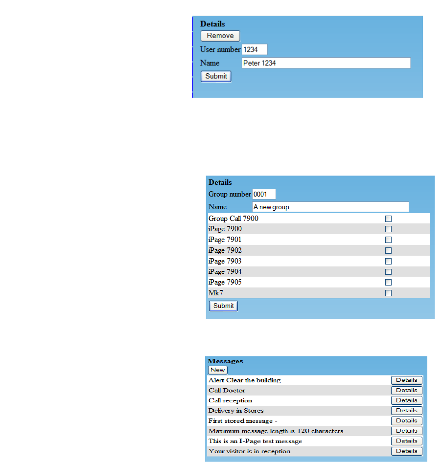
5.8 Adding groups
5.8 Adding groups
You may create up to 40 groups of pagers, each with up to 96 members.
The permitted number of characters for the user and group name is 50.
characters.
5.9 Stored messages
A maximum of 32 stored messages of 120 characters may be configured.
Add user number
Add name / description
(maximum of 50 characters)
Submit to saveTo REMOVE a
uyser, select “Remove”. There
is no prompt to check the action
is correct.
Select GROUPS
Enter 4-digit group number
Enter name / description for
group
Select all pagers to be included
within the group
Submit to save
9 i-Page Installation & User Guide 9261-8879 Iss 2
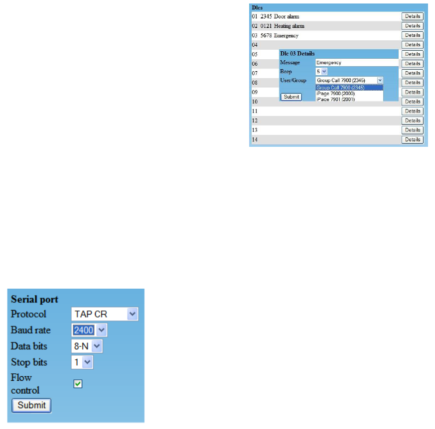
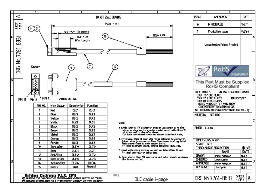
5.10 Adding DLC alarm contacts
i-Page provides 14 active closed alarm contacts. DLC’s are dry contacts and do not support
any drivers for load current.
The remote device contact must provide a Lo (Ground) volts point, or a logic value not
exceeding 3.3 volts on the alarm wire, to activate i-Page.
When a DLC is activated a message will then be sent to a user or group.
Refer to technical specification in Appendix 1 for DLC operational details and wiring.
Test the alarm contact operation
A DLC cable part number 7761-8831 may be
ordered as an accessory. This is a special cable.
5.11 Serial port
The serial port is designed to receive serial data from an external source such as a building
management or property management systems, serial alarms, fire alarms or other serial
alarm data.
i-Page supports a number of common serial alarm data protocols.
In the event that the protocol is not supported contact Multitone for advice and support.
Connection of a serial data input requires a standard 2 metre null-modem cable.
Multitone part number 7718-0030 is available for this purpose.
Select DETAILS for DLC
Input message (maximum of 120
characters).
Select beep code 1 to 8
Select user or group
Submit to save
Select SERIAL PORT
Use drop down menu to select protocol
o TAP, TAP CR, ESPA, MEP, AUSTCO,
MSP/Morley
o Baud rate
o Data bits
o Stop bits
o Flow control
Note that these settings must be the same as the
external data source
10 i-Page Installation & User Guide 9261-8879 Iss 2
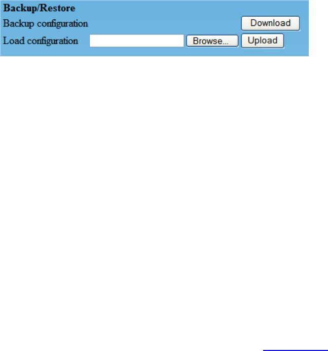
5.12 Backup and restore
The backup and restore options allow you to save system data and restore if and when
required. Always backup your system data when first setting up i-Page or when any changes
are made to the settings.
To backup system data;
DOWNLOAD
o When the “file download” screen opens select SAVE
o Give the file a name / date and save to the i-Page folder
You will need to create this folder., this should be on the local network
for safety
To restore backup system data
o BROWSE for the file to be restored and select
Select UPLOAD. Do not interrupt the upload!
5.13 Factory reset
Factory reset will clear all system data and restore all settings to default.
-Page will need to be reprogrammed, either by the re-entry of new data, or by
restoring the most recent backup file. If you select the factory reset option, you will be
presented with the following message:-
Factory Reset
Proceeding with this action will delete all devices from the database and return all
settings to factory values.
Take a backup first if there is any possibility that the existing data is required.
After the reset the i-Page unit will be available on 192.168.1.11.
Use Admin password after a factory reset and your computer will need to have the static IP
address changed to 192.168.11.1 (see section 5.1).
6.0 Engineering button
The unit has an inset small blue button which has two different functions as follows:
A) Field software upgrades (see section 10.0)
B) Identification of the unit’s IP address
The Engineering button accessible from the front of i-Page toggles between normal
operation and engineering mode when power to the unit is maintained
To activate, do not remove power, press the button in and release the button after a few
seconds.
i-Page may now be accessed from its default IP address of 192.168.1.11,allowing access
when you don’t know the unit’s IP address.
The Administration password is also temporarily set to ”Admin”.

11 i-Page Installation & User Guide 9261-8879 Iss 2
Activating the button again will return the unit to its original IP address.
When activating the button, ensure that it is depressed squarely, and released fully.
7.0 Paging users and groups
The PAGING interface allows you to:-
Send free format messages to a pager
Send free format messages to a group
Send preset messages to a user or group
Select a beep code for the message
Select PAGING from the menu.
Select one of the optional 8 beep codes
Select a user or group
Input your message or select a PRESET message
SEND the message
If no message is entered or selected, you will see a message “Error: No message entered –
call not sent.”
7.1 Logout
When administration or messaging has been completed select LOGOUT.
In the event that an administrator or user has not logged out, any other user logging in will
override the person already logged in.
This ensures that access to the paging systems is always available.
8.0 SYSLOG message tracking
If you require confirmation that the message has been sent, then you can use any one of the
freeware Syslog software packages available on the internet.
The software must be installed on a computer, preferably one that has a static IP address.
Programme the IP address of the Syslog server in the IP SETTINGS menu.
9.0 Transmitter alignment
The i-Page transmitter is factory set, according to the frequency requested when ordered. It
may be necessary to re-align the transmitter in the event of any problems or to change the
frequency.
This work must not be carried out by the user.
Please contact your supplier or maintainer, for advice or support.
Refer to Multitone document 9261-8252.
12 i-Page Installation & User Guide 9261-8879 Iss 2
10.0 Software upgrades
Upgrading software can only be carried out by your supplier or maintainer.
Programming software may be obtained from the support section of the Multitone website:-
http://www.Multitonei-Page.com.
Download the zip file and save to the computer from which programming will take place.
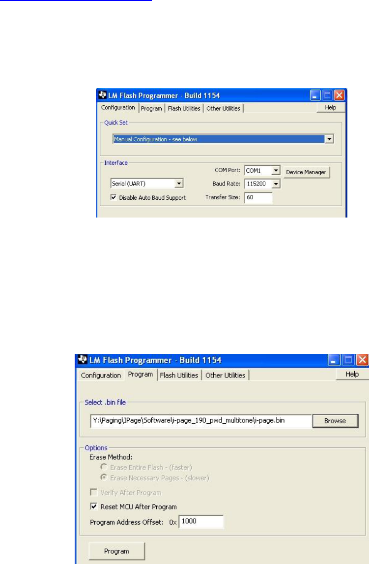
Run the program:-
"C:\Program Files\Texas Instruments\Stellaris\LM Flash Programmer\" and configure the
following options:-
Quick set - Manual configuration
Interface - Serial UART
Check - Disable baud rate
COM port - The COM port to be used for programming
Baud rate - 115200
Transfer size - 60
Select the PROGRAM menu and check the box for “Reset MCU” after program.
This ensures that i-Page will restart after the programme has been loaded.
Do not change any other menu options!
Backup i-Page data before re-programming.
13 i-Page Installation & User Guide 9261-8879 Iss 2
Field software update
The software involves a boot loader which can accept new software.
Turn the power off, wait for 10 seconds whilst the green power lamp extinguishes, depress
the button then repower the unit maintaining the button press for a few seconds. Release the
button. The green power lamp will come on, but if the ethernet cable is connected, the
ethernet LEDs will remain off. The serial port will now be available for input of a new i-Page
software issue.
Use the LM programme software to upload a new image. Connect a null modem cable
between i-Page and the computer, browse to the i-Page binary firmware file, select and
press PROGRAM.
Do not interrupt whilst the programme is being loaded and has reset i-Page, as this may
cause an irrecoverable error.
To resume normal operation after the upload, the ethernet LEDs must be flashing. If the
ethernet is not in use, then it may be advisable to repower the unit.
Check that i-Page is operating correctly and that a paging message may be sent.
14 i-Page Installation & User Guide 9261-8879 Iss 2
Appendix 1
DLC Alarm and Serial Port Technical Requirements
DLC alarm contacts
i-Page provides up to 14 alarm contacts. The cable is not supplied with i-Page and may be
ordered separately under part number 7761-8831.
The cable must be terminated in accordance with this guide.
Any damage to i-Page or customer equipment resulting from connection to high voltages is
not the responsibility of Multitone Electronics.
DLC’s are inputs only and intended for “dry” switch contacts, (no current), or simple logic
signal ports. Ideally any logic signal inputs should not exceed 3.3V.
Serial port data input
The following protocols are supported on i-Page:-
TAP MEP (Multitone protocol), ESPA 4.4.4, AUSTCO Nursecall protocol, and MSP / Morley
fires protocol.
If any other protocols are used, contact Multitone for advice and support.
We can offer a field configurable protocol converter for the majority of applications, to
convert any serial data stream into TAP or MEP protocols.
Use a standard serial Null modem cable with 9-way female connectors at each end;
Multitone part number 7718-0030.
15 i-Page Installation & User Guide 9261-8879 Iss 2
Appendix 2 – Frequently Asked Questions
I cannot log in to my i-Page:-
o Have you set the static IP address on your computer?
No – Refer to section 5.1 of installation or starter guide
o Is the static address in the same range as i-Page 192.168.1.11?
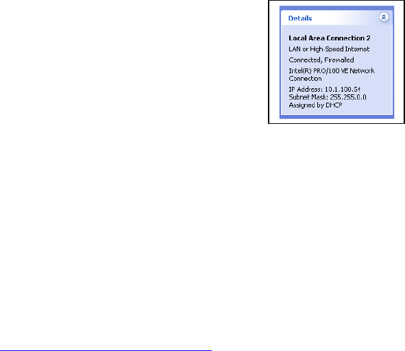
To check go to START – MY NETWORK PLACES – VIEW
NETWORK CONNECTIONS – Select Local area connection
Bottom left hand corner box DETAILS will show the IP address of your computerHow
do I know what my IP address is for Windows XP?
o Start-connect to – show all connections
o Click on “local area connection” and the details
of the connection will be shown in a box at the
lower left of the screen
I have a new pager, but it does not work.
What type of pager is it?
o If it is a Multitone pager, check the back of the pager for the frequency and
compare with the i-Page menu. What frequency is it on? Multitone pagers -
Check the back of the pager.
o Have you programmed the CAP CODE user details?
No. Use the programming guide, or go to the website and download
the video file
For more information go to http://www.multitonei-Page.com
16 i-Page Installation & User Guide 9261-8879 Iss 2
Appendix 3- i-Page Specifications
Transmitter performance - i-Page
* Frequency range: 438 to 470MHz
* Frequency stability: +/-2ppm
* Output power: 2.5W / 5W
* Duty cycle: ≤100%
* Normal load impedance: 50 ohms
* VSWR protection against short term removal of the antenna (maximum of5 calls
with antenna disconnected)
* Channel spacing factory set to: 10, 12.5, 20 or 25kHz.
* Antenna stand-alone base rear mounted loaded UHF whip, with 4metre cable UHF stub
Standard features
* Paging formats: Multitone Mk6, Mk7 and POCSAG (only one is selectable for use)
* Beep codes: 8 selectable beep codes
* Numeric messages: Up to 12 digits (Mk6)
* Alphanumeric messages: Up to 240 long text messages
* Speech transmission: Up to 256 seconds total transmission time
* Team call: Any format teams; 40 teams with up to 96 team members
* 14 DLC alarm contacts (unpowered circuits, max loop resistance 150 ohms)
* Up to 256 users (Pagers)
Protocols
Computer interface serial data, proprietary protocol, TAP, MEP, MSP, Morley, ESPA 4.4.4
and AUSTCO using RS232C. Full protocol details available upon request.
Power input
* Switch mode power supply. 110V to 240V and 1.5A
Physical
Dimensions: 105mm (w) x 175mm (d) x 65mm (h)
Weight: 700g
Environment
Operating temperature: -10°C to +55°C
17 i-Page Installation & User Guide 9261-8879 Iss 2
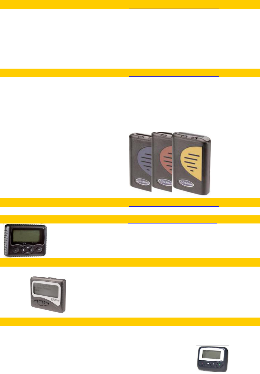
Appendix 4 – Multitone pagers
Multitone can offer a range of pagers for use with i-Page
RPR580 paging receiver Mk7
Part no.
http://www.multitonei-Page.com
UHF receiver
UHF receiver
RPR583MK4
Selectable 2-line or 4-line alphanumeric display
.3 selectable display fonts
. Icon driven operation
. Up to 1,000 character message length
. Multiple message memories store up to 24,000 chtrs
. 8 information service mailboxes
. Selectable audible and/or vibrate alert
. Free holster and lanyard
. Runs on one AAA battery
. Battery saver
RPR750 paging receiver
Part no.
http://www.multitonei-Page.com
RPR750 Mk6
The RPR750 is supplied in a tough, dustproof and
water-resistant case, protected to IP54. The specially
designed grip-tight clip enables you to carry your pager
safely.
Safe (ATEX) versions are also available, allowing the
RPR750 to operate in most hazardous and hostile
environments.
UHF Receiver Mk6
RPR753MK6
RPR750 Mk6 Intrinsically Safe
UHF receiver Mk6 IS
RPR753MK6IS
RPR750 Mk7
UHF Receiver Mk7
RPR753MK7
RPR750MK7 Intrinsically Safe
UHF Receiver Mk7 IS
RPR753MK7IS
RPR750 POCSAG
UHF Receiver POCSAG
RPR753POC
RPR750 POCSAG Intrinsically Safe
UHF Receiver POCSAG IS
RPR753POCIS
TLA850 paging receiver
Part no.
http://www.multitonei-Page.com
UHF POCSAG
TLA853Mk2
Waterproof pager
Part no.
http://www.multitonei-Page.com
TPW-WP
Robust waterproof and dustproof.
POCSAG pager. IP67 rated.
8 RIC codes with 4 sub addresses.
Alarm contact on pager cradle.
MIT870 series pagers
Part no.
http://www.multitonei-Page.com
UHF POCSAG
MIT873
MIT873IS
Display LCD 6-line:150 (6 rows of 25 characters).
Display LCD 4-line: (normal): 100 (4 rows of 25
characters). Display LCD 4-line (bold): 64 (4 rows of 16
characters).
POCSAG pager
Frequency
http://www.multitonei-Page.com
See Multitone price list
•2-line, 2-line bold or 4-line alphanumeric display
•20 characters per line display (2-line: 40 characters, 4-
line 80 characters)
•8 CAP CODES
•Synthesised frequency
•50 message capacity
•Priority tone override
UHF
448-452MHz,
UHF
452-456MHz
UHF
456-460MHz
UHF
460-464MHz
UHF
464-468MHz
UHF
468-472MHz
18 i-Page Installation & User Guide 9261-8879 Iss 2
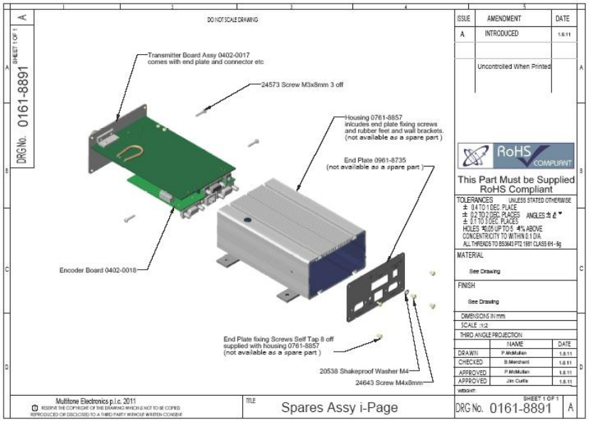
Appendix 5 – i-Page Spares
Spares will be limited to complete field replaceable components.
Main spares
Transmitter board and endplate assembly - 0402-0017
Encoder board assembly - 0402-0018
i-Page IP133 housing - 0761-8857
End plate - 0761-8857

19 i-Page Installation & User Guide 9261-8879 Iss 2
Multitone Electronics plc, Multitone House, Shortwood Copse Lane, Basingstoke, England, RG23 7NL
Telephone: +44 (0)1256 320292 Fax: +44 (0)1506 462643 Email: info@multitone.com Web: www.multitone.com
This document is for guidance only. Products and services offered are subject to availability and may differ from those described or
illustrated in this document as a result of changes. Specifications are subject to change without notice. Multitone Electronics plc is
part of Kantone Holding Ltd, a member of the Champion Technology group of companies. Registered office: Multitone Electronics plc,
Shortwood Copse Lane, Kempshott, Basingstoke, Hampshire, RG23 7NL. Registered in England No. 256314.
9261 – 8879 Iss. 1
Cert No.
FM 20122